EP2641768A1 - Dispositif d'obturation de gril - Google Patents
Dispositif d'obturation de gril Download PDFInfo
- Publication number
- EP2641768A1 EP2641768A1 EP13160055.3A EP13160055A EP2641768A1 EP 2641768 A1 EP2641768 A1 EP 2641768A1 EP 13160055 A EP13160055 A EP 13160055A EP 2641768 A1 EP2641768 A1 EP 2641768A1
- Authority
- EP
- European Patent Office
- Prior art keywords
- frame
- actuator
- grill
- engagement
- front side
- Prior art date
- Legal status (The legal status is an assumption and is not a legal conclusion. Google has not performed a legal analysis and makes no representation as to the accuracy of the status listed.)
- Granted
Links
Images


Classifications
-
- B—PERFORMING OPERATIONS; TRANSPORTING
- B60—VEHICLES IN GENERAL
- B60K—ARRANGEMENT OR MOUNTING OF PROPULSION UNITS OR OF TRANSMISSIONS IN VEHICLES; ARRANGEMENT OR MOUNTING OF PLURAL DIVERSE PRIME-MOVERS IN VEHICLES; AUXILIARY DRIVES FOR VEHICLES; INSTRUMENTATION OR DASHBOARDS FOR VEHICLES; ARRANGEMENTS IN CONNECTION WITH COOLING, AIR INTAKE, GAS EXHAUST OR FUEL SUPPLY OF PROPULSION UNITS IN VEHICLES
- B60K11/00—Arrangement in connection with cooling of propulsion units
- B60K11/02—Arrangement in connection with cooling of propulsion units with liquid cooling
- B60K11/04—Arrangement or mounting of radiators, radiator shutters, or radiator blinds
-
- B—PERFORMING OPERATIONS; TRANSPORTING
- B60—VEHICLES IN GENERAL
- B60K—ARRANGEMENT OR MOUNTING OF PROPULSION UNITS OR OF TRANSMISSIONS IN VEHICLES; ARRANGEMENT OR MOUNTING OF PLURAL DIVERSE PRIME-MOVERS IN VEHICLES; AUXILIARY DRIVES FOR VEHICLES; INSTRUMENTATION OR DASHBOARDS FOR VEHICLES; ARRANGEMENTS IN CONNECTION WITH COOLING, AIR INTAKE, GAS EXHAUST OR FUEL SUPPLY OF PROPULSION UNITS IN VEHICLES
- B60K11/00—Arrangement in connection with cooling of propulsion units
- B60K11/08—Air inlets for cooling; Shutters or blinds therefor
- B60K11/085—Air inlets for cooling; Shutters or blinds therefor with adjustable shutters or blinds
-
- B—PERFORMING OPERATIONS; TRANSPORTING
- B60—VEHICLES IN GENERAL
- B60Y—INDEXING SCHEME RELATING TO ASPECTS CROSS-CUTTING VEHICLE TECHNOLOGY
- B60Y2304/00—Optimising design; Manufacturing; Testing
- B60Y2304/05—Reducing production costs, e.g. by redesign
-
- Y—GENERAL TAGGING OF NEW TECHNOLOGICAL DEVELOPMENTS; GENERAL TAGGING OF CROSS-SECTIONAL TECHNOLOGIES SPANNING OVER SEVERAL SECTIONS OF THE IPC; TECHNICAL SUBJECTS COVERED BY FORMER USPC CROSS-REFERENCE ART COLLECTIONS [XRACs] AND DIGESTS
- Y02—TECHNOLOGIES OR APPLICATIONS FOR MITIGATION OR ADAPTATION AGAINST CLIMATE CHANGE
- Y02T—CLIMATE CHANGE MITIGATION TECHNOLOGIES RELATED TO TRANSPORTATION
- Y02T10/00—Road transport of goods or passengers
- Y02T10/80—Technologies aiming to reduce greenhouse gasses emissions common to all road transportation technologies
- Y02T10/88—Optimized components or subsystems, e.g. lighting, actively controlled glasses
Definitions
- This disclosure relates to a grill shutter device.
- grill shutter devices capable of controlling a flow rate of air flowing into an engine compartment from a grill opening portion, based on an opening and closing operation of a shutter mechanism provided in the grill opening portion of a vehicle body front portion (for example, see JP-UM-58-139519A (Reference 1).
- aerodynamic performance for example, "Cd value” or the like
- the warming-up time thereof can be shortened.
- the engine temperature can be suitably managed.
- JP 2003-81034A (Reference 2) discloses a configuration in which a load transmission member is provided on the back surface of the front grill, and the collision load is transmitted to an accommodation device in the engine compartment such as a radiator. Moreover, it is possible to rapidly absorb the collision load and effectively alleviate the impact by adopting such a structure.
- This disclosure has been made in order to solve the above-mentioned problems, and a need thus exists for a grill shutter device capable of alleviating the collision load applied to the accommodation device of the inner portion of the vehicle body placed in the rear at the time of the vehicle collision.
- a grill shutter device configured to be placed to a grill opening portion of a vehicle body front portion including a shutter mechanism controlling a flow rate of air flowing into a vehicle body from the grill opening portion of the vehicle body front portion by an opening and closing operation; a frame configured to support the shutter mechanism within the grill opening portion; an actuator that is held in the frame and performs the opening and closing driving of the shutter mechanism; and a holding structure capable of relatively moving the actuator to the front side of the frame, based on the collision load at the time of the vehicle collision.
- the grill shutter device may include a cover member that covers the front side of the actuator by being affixed to the frame, the cover member may be fixed to the frame by the engagement between a first engagement portion provided on the cover member side with a second engagement portion provided on the frame side, and the engagement between the first engagement portion with the second engagement portion may be released based on the collision load.
- the actuator can be protected and aerodynamic performance can be improved. Furthermore, an improvement in design properties can be planned. Moreover, like the above-mentioned configuration, by the engagement between the first engagement portion provided on the cover member side with the second engagement portion provided on the frame side, the cover member is fixed to the frame, and thus favorable assembly properties can be secured.
- the cover member is located on the front side of the actuator, holding force due to the cover member can be applied to the actuator. Thereby, high assembly rigidity can be secured at a normal time. Moreover, when the collision load is input, the engagement between the first engagement portion with the second engagement portion is released, whereby the actuator can be relatively moved to the front side of the frame.
- At least one of the frame and the actuator may be formed with a protrusion portion that extends in a front-back direction of the frame in a state where the actuator is held in the frame, and the other thereof may be formed with a groove portion fitted to the protrusion portion.
- the relative movement of the actuator in directions other than the front-back direction of the frame, in which the protrusion portion extends, is restricted.
- high assembly properties at a normal time can be secured.
- the front-back direction of the frame it is possible to permit the relative movement of the actuator with respect to the frame.
- At least one of the protrusion portion and the groove portion may be formed with a projection portion that generates the holding force in the front-back direction by coming into contact with the other thereof within the groove portion.
- the shutter mechanism may be provided with a rotation input portion that is connected to an output shaft of the actuator so as to be able to transmit the rotation, and is able to release the connection with the output shaft without disturbing the relative movement of the actuator to the front side at a predetermined rotation position.
- the rotation input portion may be provided with a fitting groove that is opened to the front side at the predetermined rotation position
- the output shaft may be formed so as to be able to be fitted to the fitting groove in a relatively non-rotatable manner and so as to be able to be detached from the opening portion of the front side.
- connection between the actuator with the shutter mechanism can be released based on the collision load.
- the actuator may have a portion projecting rearward from the rear end portion of the frame and may be held in the frame.
- a rearward projecting portion of the actuator comes into contact with any part in the grill opening portion, and thus the actuator is pressed toward to the front side of the frame.
- the actuator is pressed toward to the front side of the frame.
- the actuator may be held in a central portion in a width direction in the frame.
- the actuator held in the frame is more likely directly to come into contact with the accommodation device placed in the rear.
- the grill shutter device capable of alleviating the collision load applied to the accommodation device of the inner portion of the vehicle body placed in the rear, at the time of the vehicle collision.
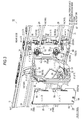
- a radiator 5 for cooling an engine 4 thereof is accommodated in an engine compartment 3 formed inside a vehicle body 2. Furthermore, in a front portion (a left end portion in Fig. 1 ) of the vehicle body 2, a grill opening portion 7 is formed through which an outer space of the front of the vehicle and an inner space of the vehicle body 2 communicate with each other. Moreover, the radiator 5 is placed ahead of the engine 4 so that the air flowing into the engine compartment 3 from the grill opening portion 7 hits thereon.
- a fan 6 is provided behind (a right side in Fig. 1 ) the radiator 5. Moreover, the fan 6 rotates, whereby the air effectively flows through the radiator 5.
- the grill opening portion 7 is formed below a bumper 8. Furthermore, a front grill 9 constituting a design surface (a lower grill) thereof is affixed to an opening end 7a of the grill opening portion 7. Moreover, the vehicle 1 of the present embodiment includes a grill shutter device 10 capable of controlling the flow rate of the air flowing into the engine compartment 3 from the grill opening portion 7.
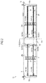
- the grill shutter device 10 includes a shutter mechanism 11 capable of controlling the flow rate of the air based on the opening and closing operation, a frame 12 as a structure that supports the shutter mechanism 11 within the grill opening portion 7, and an actuator 13 that is held in the frame 12 and performs the opening and closing driving of the shutter mechanism 11.
- the frame 12 is formed in a substantially laterally long square framework shape extending in a width direction of the vehicle body 2. Furthermore, the shutter mechanism 11 is formed by arranging and placing a plurality of movable fins 14 within the framework of the frame 12.
- the frame 12 is provided with an actuator holding portion 15 that holds the actuator 13.
- the frame 12 and the shutter mechanism 11 are formed by resin.
- the frame 12 is placed within the grill opening portion 7 by fixing an upper framework portion 16 thereof to a bumper reinforcement 17.
- the actuator 13 of the present embodiment is formed by accommodating a motor, a decelerator or the like (not shown) within a flat box-like case 18.
- the actuator 13 includes an output shaft 20, both end portions of which project from a side plate portion 19 of the two surfaces thereof. Moreover, there is provided a configuration in which the actuator 13 is held in the frame 12 so that the extension direction of the output shaft 20 follows the width direction (see Fig. 2 , a longitudinal direction) of the frame 12.
- the actuator holding portion 15 of the present embodiment includes a pair of side walls 22 (22a and 22b) standing substantially in parallel in a central portion in the width direction of the frame 12. Furthermore, the actuator holding portion 15 has an opening portion 23 through which the actuator 13 can pass, on the front side (see Fig. 1 , the left side) of the frame 12. Moreover, the actuator 13 is mounted to the actuator holding portion 15 from the front side of the frame 12 by passing through the opening portion 23.
- a cover member 24 configured to cover the front side of the actuator 13 held in the actuator holding portion 15 is affixed to the opening portion 23. Moreover, thereby, the actuator holding portion 15 of the present embodiment has a substantially columnar external form when viewed from the front (see Fig. 2 ).
- the shutter mechanism 11 includes a plurality of movable fins 14 provided in parallel in two rows within each of the flow paths 25A and 25B.
- each movable fin 14 includes a substantially long flat plate-like fin portion 28 extending in the width direction of the frame 12, and has a rotation shaft 30 that is spanned between each of the side walls 22a and 22b forming the actuator holding portion 15 and side walls 12a and 12b of the frame 12 facing the same. Furthermore, the actuator 13 held in the actuator holding portion 15 is able to open and close the shutter mechanism 11 by rotating and driving of each rotation shaft 30.
- the shutter mechanism 11 of the present embodiment enters the opened state by the rotation of each movable fin 14 in a direction (a clockwise direction in Fig. 2 ) in which the fin portion 28 enters a state of being parallel to the in-flow direction of the air flowing in from the grill opening portion 7. Moreover, the shutter mechanism 11 enters the closed state by the rotation of each movable fin 14 in a direction (a counterclockwise direction in Fig. 2 ) in which the fin portion 28 enters a state of intersecting with the in-flow direction of the air.
- the grill shutter device 10 of the present embodiment controls the rotation of each movable fin 14 using the actuator 13. Moreover, it is possible to control the flow rate of the air flowing into the engine compartment 3 from the grill opening portion 7, based on the opening and closing operation of the shutter mechanism 11 due to the rotation of each movable fin 14.
- protrusion portions 31 extending in the front-back direction of the frame 12 shown in Fig. 4 are each provided. Furthermore, as shown in Fig. 3 , in the present embodiment, on inner wall surfaces S1 of each of the side walls 22a and 22b forming the actuator holding portion 15, protrusion portions 31 extending in the front-back direction of the frame 12 shown in Fig. 4 are each provided. Furthermore, as shown in FIG. 3 , in the present embodiment, on inner wall surfaces S1 of each of the side walls 22a and 22b forming the actuator holding portion 15, protrusion portions 31 extending in the front-back direction of the frame 12 shown in Fig. 4 are each provided. Furthermore, as shown in
- the actuator 13 of the present embodiment is inserted into the actuator holding portion 15 from the front side of the frame 12 via the opening portion 23 so that the protrusion portion 31 and the groove portion 32 are fitted to each other.
- the protrusion portions 31 are provided near the upper end portion and the lower end portion (portions shown in areas ⁇ ( ⁇ 1 and ⁇ 2) in Fig. 3 ) on the inner wall surface S1 of each of the side walls 22a and 22b. Furthermore, each of the connection members 33 are fixed to the vicinity of the upper end portion and the lower end portion (portions shown in areas ⁇ ( ⁇ 1 and ⁇ 2) in Fig. 3 ) in each side plate portion 19 of each case 18.
- connection member 33 of the present embodiment is formed by an elastically deformable material (resin). Moreover, as shown in Fig. 6 , the relative movement of the actuator 13 with respect to the frame 12 is restricted in directions other than the front-back direction of the frame 12 in which each protrusion portion 31 extends, by fitting of each protrusion portion 31 and the groove portion 32 of each connection member 33.
- each groove portion 32 has an opening end 34 at one end (an end portion in the longitudinal direction located on the right side in Fig. 5 ), is fitted to each protrusion portion 31, and has projection portions 35 and 36 vertically facing each other and projecting into the groove portion so as to interpose each protrusion portion 31 therebetween.
- each groove portion 32 a projection portion 37 pressing a top portion 31a of each fitting protrusion portion 31 in the width direction is provided.
- the projection portions 35 and 36 and the projection portion 37 are each provided at a plurality of locations (two locations) in the extension direction of each groove portion 32.
- constant holding force is also generated in the front-back direction (see Fig. 1 , the longitudinal direction in Fig. 1 ) of the frame 12.
- the actuator 13 of the present embodiment is mounted to the actuator holding portion 15 by the application of pressing force of an extent that can push each protrusion portion 31 of the frame 12 side into each groove portion 32 by elastically deforming each of the projection portions 35 to 37.
- the actuator 13 has a portion projecting rearward rather than a rear end 16a of the upper framework portion 16 serving as the rear end portion of the frame 12, and is held in the frame 12. Moreover, force in the direction opposite to that at the time of mounting, that is, by the application of force which pulls the actuator 13 to the front side of the frame 12 in response to the holding force generated by each of the projection portions 35 and 36 and the projection portion 37, it is possible to detach the actuator 13 from the actuator holding portion 15.
- each movable fin 14 forming the shutter mechanism 11 is configured so that one end (a proximal end 30a) of the rotation shaft 30 is supported rotatably by each of the side walls 22a and 22b forming the actuator holding portion 15.
- each side wall 22 (22a and 22b) is formed with a notch 43 opened to the front side of the frame 12 (see
- each movable fin 14 is affixed to the frame 12 in the manner of fitting a shaft 44 interposed between each of the flanges 41 and 42 to the bottom portion of the notch 43 formed in a substantially U shape.
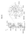
- the cover member 24 covering the front side (the lower side in Fig. 9 and the left side in Fig. 10 ) of the actuator holding portion 15 includes a pair of holding walls 45 (45a and 45b) provided at the positions in the width direction corresponding to each side wall 22 (22a and 22b). Moreover, each of the holding walls 45 (45a and 45b) is formed with a substantially semi-circular concave portion 46 that comes into sliding-contact with the shaft portion 44 of each rotation shaft 30 fitted to each notch 43 as mentioned above.
- each notch 43 is blocked by each of holding walls 45 (45a and 45b) by fixing of the cover member 24 to the opening portion 23 of the actuator holding portion 15.
- a bearing portion is formed which rotatably supports (the shaft portion 44 of) the proximal end 30a of each rotation shaft 30 to each of the side walls 22a and 22b.
- a rotation link 48 rotating integrally with each rotation shaft 30 is fixed to each rotation shaft 30. Furthermore, a connection link 49 connecting each leading end 48a positioned vertically is provided in the leading end 48a of each rotation link 48. Moreover, thereby, the shutter mechanism 11 of the present embodiment has a configuration in which each of vertical movable fins 14A and 14B rotates synchronously.
- a fitting groove 51 is formed which is opened to a shaft end surface 50 and can be fitted to the output shaft 20 of the actuator 13 so as to be able to transmit the rotation.
- the shutter mechanism 11 of the present embodiment is configured so that (the proximal end 30a) of each rotation shaft 30 of each lower movable fin 14B is connected to the actuator 13 as a rotation input portion.
- the leading end shape of the output shaft 20 of the actuator 13 is a so-called two surface width shape having flat surfaces 20a and 20b of two surfaces substantially parallel to each other (see Fig. 3 , a portion shown in an area ⁇ ).
- the fitting groove 51 of each rotation shaft 30 side is formed so that a groove width W is substantially the same as a distance D between both flat surfaces 20a and 20b in the output shaft 20, that is, a thickness of the two surface width-shaped portion.
- the output shaft 20 of the actuator 13 is fitted to the fitting groove 51 of each rotation shaft 30 forming the rotation input portion in a relatively non-rotatable manner.
- the fitting groove 51 has a peripheral surface opening portion 52 that is opened to the peripheral surface of (the proximal end 30a of) each rotation shaft 30 in the state of notching a part in the circumferential direction in each of the flanges 41 and 42.
- each movable fin 14 is placed so that the peripheral surface opening portion 52 is located on the opening end 43a side of the notch 43 forming the bearing portion of each rotation shaft 30, that is, the front side of the frame 12, when the rotation shaft 30 is located at the predetermined rotation position.
- each movable fin 14 is mounted to the frame 12 so that the peripheral surface opening portion 52 of the fitting groove 51 faces the front side of the frame 12 at the rotation position in which the shutter mechanism 11 enters the fully-opened state.
- the output shaft 20 of the actuator 13 is fitted to each fitting groove 51 via the peripheral surface opening operation 52 when the actuator 13 is mounted to the actuator holding portion 15.
- the cover member 24 includes a main body portion 53 that is formed in a substantially flat shape so as to cover the opening portion 23 of the actuator holding portion 15, and a pair of turn-up portions 54 (54a and 54b) that protrude and are formed so as to be covered by an outer wall surface S2 of each of the side walls 22a and 22b forming the actuator holding portion 15 from both ends in the width direction of the main body portion 53.
- the cover member 24 is fixed to the frame 12 by the engagement of both of the turn-up portions 54 (54a and 54b) with each of the side walls 22 (22a and 22b).
- the cover member 24 of the present embodiment is formed by an elastically deformable material (resin). Furthermore, as shown in Fig. 12 , in each of the turn-up portions 54 of the cover member 24, an engagement hole 55 is formed. Moreover, as shown in Fig. 13 , each side wall 22 (22a and 22b) of the frame 12 side is formed with an engagement projection portion 56.
- each engagement projection portion 56 has an inclined surface 56a expanding outward in the width direction (the longitudinal direction in Fig. 6 ) toward the rear side from the front side of the frame 12 (from the lower side to upper side in Fig. 6 ), and is formed on the outer wall surface S2 of each of the side walls 22a and 22b.
- each engagement projection portion 56 has a locking wall 56b that is substantially perpendicular to the outer wall surface S2 of each of the side walls 22 (22a and 22b) on the rear side (the upper side in Fig. 6 ) of the frame 12.
- each engagement projection portion 56 is inserted into each engagement hole 55, whereby both of the turn-up portions 54a and 54b are engaged with the side walls 22a and 22b.
- both of the turn-up portions 54a and 54b of the cover member 24 cooperate with each engagement projection portion 56 of the side walls 22a and 22b sides to form a so-called snap-fit. That is, by locking the locking wall 56b of each engagement projection portion 56 with an inner circumferential surface 55a of a leading end side (the upper side in Fig. 6 ) in each engagement hole 55, the relative movement of the cover member 24 to the front side of the frame 12 is restricted. Moreover, the cover member 24 serves as a stopper, whereby it is possible to restrict the relative movement of the actuator 13 to the front side of the frame 12 and generate constant holding force.
- each engagement hole 55 and each engagement projection portion 56 are each provided in the upper end portion and the central portion in the corresponding both of the turn-up portions 54 (54a and 54b) and the side walls 22 (22a and 22b) (portions shown in areas ⁇ ( ⁇ 1 and ⁇ 2) and areas ⁇ ( ⁇ 1 and ⁇ 2) in Fig. 3 ).
- a plurality of (two in the present embodiment) engagement claws 58 projecting upward are provided, and the main body portion 53 of the cover member 24 is provided with an engagement target portion 59 engaged with each engagement claw 58 (an area in Fig. 3 ).
- the lower end portion of the cover member 24 is fixed to the frame 12 by the engagement between each engagement claw 58 and each engagement target portion 59.
- a portion forming the inner circumferential surface 55a of each engagement hole 55 locked to the locking wall 56b of each engagement projection portion 56 is a thin portion 60 having relatively low strength.
- each thin portion 60 is deformed or breaks, whereby the engagement between each engagement hole 55 and each engagement projection portion 56 is released.
- the actuator 13 In the grill shutter device 10 of the present embodiment, heavy loads such as a motor and a decelerator are concentrated on the actuator 13. That is, unless the collision load directly acts on actuator 13, the actuator 13 maintains the movement state before the collision based on inertia, that is, tries to relatively move forward with respect to the frame 12 moving back due to the input of the collision load. Furthermore, the actuator 13 has a portion that projects rearward rather than the rear end portion (the rear end 16a of the upper framework portion 16) of the frame 12 in the state of being held in the frame 12. Moreover, the portion comes into contact with any part in the grill opening portion 7 earlier than the frame 12, whereby the portion tries to relatively move forward with respect to the frame 12.
- the grill shutter device 10 of the present embodiment permits the relative movement of the actuator 13 based on the input of the collision load, specifically, the relative movement toward the front side of the frame 12. Moreover, a configuration is provided in which, at the time of the vehicle collision, for example, when the grill shutter device 10 comes into contact with the accommodation device in the engine compartment 3 placed in the rear, such as the radiator 5, due to the relative movement of the actuator 13, the collision load applied to the accommodation device is alleviated.
- the actuator 13 has each protrusion portion 31 provided on the inner wall surface S1 of each of the side walls 22a and 22b forming the actuator holding portion 15, and the groove portion 32 corresponding to each protrusion portion 31, and is held in the actuator holding portion 15 in the fitted state of the connection member 33 provided in each side plate portion 19.
- the proximal end 30a of) the rotation shaft 30 of each movable fin 14 is formed with the fitting groove 51 that is opened to the shaft end surface 50 and can be fitted to the output shaft 20 of the actuator 13 so as to enable the transmit of the rotation. Moreover, thereby, the rotation shaft 30 of each movable fin 14 functions as the rotation input portion of the shutter mechanism 11. Furthermore, the fitting groove 51 has the peripheral surface opening portion 52 opened to the front side of the frame 12, at the rotation position of each rotation shaft 30 in which the shutter mechanism 11 enters the fully-opened state.
- each engagement hole 55 of both of the turn-up portions 54a and 54b provided as the first engagement portion of the cover member 24 side is engaged with each engagement projection portion 56 provided on each of the side walls 22a and 22b as the second engagement portion of the frame 12 side, whereby the cover member 24 is fixed to the frame 12 so as to cover the front side of the actuator 13.
- the actuator 13 relatively moves in the actuator holding portion 15 to the front side of the frame 12 and presses the cover member 24 fixed to the opening portion 23 based on the collision load, whereby each thin portion 60 of both of the turn-up portions 54a and 54b forming the engagement hole 55 is deformed or breaks. Moreover, thereby, the engagement between each engagement hole 55 and each engagement projection portion 56 is released and the cover member 24 is detached from the opening portion 23 of the actuator holding portion 15. Thus, the detachment of the actuator 13 to the front side of the frame 12 via the opening portion 23 is permitted.
- the "detachment" of the cover member 24 and the actuator 13 in this case is the meaning of the broad sense that includes a complete detached state of dropping out from the frame 12 as well as a state where the combination with the frame 12 partially remains.
- the frame 12 has a holding structure capable of relatively moving the actuator 13 to the front side thereof, based on the collision load at the time of the vehicle collision.
- the components of the actuator 13 are hard and have high strength.
- the actuator 13 by relatively moving the actuator 13 to the front side of the frame 12 at the time of the vehicle collision, for example, when the grill shutter device 10 comes into contact with the accommodation device in the engine compartment 3, such as the radiator 5, placed in the rear, the collision load applied to the accommodation device can be alleviated.
- the accommodation device in the engine compartment is influenced.
- it is possible to alleviate the consumers' burden such as a labor and a time required for the repair and the exchange thereof or the cost.
- the actuator 13 can be protected and thus the aerodynamic performance can be improved. Furthermore, an improvement in design properties can also be planned. Moreover, like the above-mentioned configuration, the cover member 24 is fixed to the frame 12 by the engagement between each engagement hole 55 provided on the cover member 24 side and each engagement projection portion 56 provided on the frame 12 side, whereby the satisfactory assembly properties can be secured.
- the cover member 24 is located on the front side of the actuator 13, it is possible to apply the holding force due to the cover member 24 to the actuator 13. Thereby, high assembly rigidity can be secured at a normal time. Moreover, when the collision load is input, the engagement between each engagement hole 55 and each engagement projection portion 56 is released, whereby the actuator 13 can be relatively moved to the front side of the frame 12.
- connection member 33 having the groove portion 32 capable of being fitted to the protrusion portion 31 is affixed to the actuator 13. Moreover, the actuator 13 is held in the actuator holding portion 15 in the state where the protrusion portion 31 and the groove portion 32 are fitted to each other.
- the relative movement of the actuator 13 in directions other than the front-back direction of the frame 12 is restricted.
- the high assembly rigidity at the normal time can be secured.
- the front-back direction of the frame 12 it is possible to permit the relative movement of the actuator 13 with respect to the frame 12.
- the constant holding force (frictional force) is also generated in the front-back direction of the frame 12, based on the contact between the respective projection portions 35, 36 and 37 and each of the protrusion portions 31.
- high assembly rigidity can be secured at a normal time.
- the rotation shaft 30 of each movable fin 14 functions as the rotation input portion of the shutter mechanism 11. Furthermore, when the vehicle collision occurs, in a case where each rotation shaft 30 is located at the predetermined rotation position, the connection between the output shaft 20 of the actuator 13 and each rotation shaft 30 is released, without disturbing the relative movement of the actuator 13 to the front side of the frame 12. As a result, it is possible to more smoothly and relatively move the actuator 13 to the front side of the frame 12, based on the collision load.
- the above-mentioned embodiment may be modified as follows.
- the air flowing in from the grill opening portion 7 is taken into the engine compartment 3 formed in the vehicle body 2.
- the intake destination of the air may not be the engine compartment 3, without being limited thereto.
- the accommodation chamber of the heat exchanger such as the radiator 5
- this configuration may be applied to a vehicle in which an engine is placed in the rear portion or the center of the vehicle body, or a vehicle in which an engine is not equipped in the in-vehicle space ahead of the vehicle compartment such as an electric car.
- the actuator 13 has the portion projecting rearward rather than the rear end portion (the rear end portion 16a of the upper framework portion 16) of the frame 12, and is held in the frame 12.
- the rear end portion of the actuator 13 is located ahead of the rear end portion of the frame 12, without being limited thereto.
Landscapes
- Engineering & Computer Science (AREA)
- Chemical & Material Sciences (AREA)
- Combustion & Propulsion (AREA)
- Transportation (AREA)
- Mechanical Engineering (AREA)
- Cooling, Air Intake And Gas Exhaust, And Fuel Tank Arrangements In Propulsion Units (AREA)
Applications Claiming Priority (1)
| Application Number | Priority Date | Filing Date | Title |
|---|---|---|---|
| JP2012065931A JP5853801B2 (ja) | 2012-03-22 | 2012-03-22 | グリルシャッタ装置 |
Publications (2)
| Publication Number | Publication Date |
|---|---|
| EP2641768A1 true EP2641768A1 (fr) | 2013-09-25 |
| EP2641768B1 EP2641768B1 (fr) | 2014-08-27 |
Family
ID=47913127
Family Applications (1)
| Application Number | Title | Priority Date | Filing Date |
|---|---|---|---|
| EP13160055.3A Active EP2641768B1 (fr) | 2012-03-22 | 2013-03-19 | Dispositif d'obturation de gril |
Country Status (4)
| Country | Link |
|---|---|
| US (1) | US8960343B2 (fr) |
| EP (1) | EP2641768B1 (fr) |
| JP (1) | JP5853801B2 (fr) |
| CN (1) | CN203186081U (fr) |
Cited By (6)
| Publication number | Priority date | Publication date | Assignee | Title |
|---|---|---|---|---|
| EP3002145A1 (fr) * | 2014-09-30 | 2016-04-06 | Faltec Company Limited | Obturateur à grille de véhicule, élément de volet de véhicule et actionneur |
| FR3046757A1 (fr) * | 2016-01-20 | 2017-07-21 | Valeo Systemes Thermiques | Systeme de gestion d'entree d'air pour obturateur actif de calandre |
| WO2019012200A1 (fr) * | 2017-07-12 | 2019-01-17 | Valeo Systemes Thermiques | Dispositif de regulation d'entree d'air pour vehicule automobile |
| WO2019020510A1 (fr) * | 2017-07-28 | 2019-01-31 | Valeo Systemes Thermiques | Dispositif d'obturation d'entree d'air de vehicule automobile et procede de fabrication d'un tel dispositif d'obturation |
| WO2019043315A1 (fr) * | 2017-09-01 | 2019-03-07 | Valeo Systemes Thermiques | Volet d'obturation pour dispositif de regulation d'un flux d'air pour module de face avant pour vehicule automobile |
| US11142060B2 (en) | 2018-10-24 | 2021-10-12 | Batz, S. Coop. | Shutter device for a front grille of a vehicle |
Families Citing this family (25)
| Publication number | Priority date | Publication date | Assignee | Title |
|---|---|---|---|---|
| CN1952602A (zh) * | 2005-10-18 | 2007-04-25 | 国际商业机器公司 | 在空间中为用户定向的方法和装置 |
| FR2978087B1 (fr) * | 2011-07-21 | 2013-08-23 | Valeo Systemes Thermiques | Dispositif d'obturation d'orifice de face avant de vehicule automobile. |
| EP2746111A4 (fr) * | 2011-08-20 | 2015-03-11 | Ams Co Ltd | Calandre de véhicule |
| JP5807486B2 (ja) * | 2011-09-28 | 2015-11-10 | アイシン精機株式会社 | グリルシャッタ装置 |
| JP5895893B2 (ja) * | 2013-04-02 | 2016-03-30 | トヨタ自動車株式会社 | 車両 |
| GB2514377A (en) * | 2013-05-21 | 2014-11-26 | Johnson Electric Sa | Actuator with progressive gear |
| CN105745109A (zh) * | 2013-11-23 | 2016-07-06 | 戴姆勒股份公司 | 车辆用散热器格栅装置 |
| JP2015214211A (ja) * | 2014-05-09 | 2015-12-03 | アイシン精機株式会社 | 車両用グリル装置 |
| JP6236381B2 (ja) * | 2014-12-25 | 2017-11-22 | 株式会社ファルテック | 車両用グリルシャッタ、車両用フラップ部材及びアクチュエータ |
| JP6155249B2 (ja) * | 2014-12-26 | 2017-06-28 | 株式会社ファルテック | グリルシャッタモジュール |
| DE102015109698B4 (de) * | 2015-06-17 | 2021-06-24 | Hbpo Gmbh | Kühlsystem für ein Fahrzeug |
| KR101637305B1 (ko) * | 2015-07-13 | 2016-07-20 | 현대자동차 주식회사 | 자동차의 기류 유도 장치 |
| US9840144B2 (en) * | 2015-08-19 | 2017-12-12 | Mazda Motor Corporation | Front air-rectifying structure of automotive vehicle |
| JP6292196B2 (ja) * | 2015-08-28 | 2018-03-14 | トヨタ自動車株式会社 | 車両前部の吸気構造 |
| US9828044B2 (en) * | 2015-09-25 | 2017-11-28 | GM Global Technology Operations LLC | Feedback control of vehicle aerodynamics |
| JP6598975B2 (ja) * | 2016-02-29 | 2019-10-30 | 三菱電機株式会社 | 車両用冷却装置 |
| EP3235671B1 (fr) * | 2016-04-19 | 2019-04-10 | Batz, S.Coop. | Dispositif d'obturation pour une calandre d'un véhicule |
| CN109564024B (zh) * | 2016-08-12 | 2021-03-26 | 麦格纳外饰公司 | 主动格栅的可扩展设计 |
| JP6816479B2 (ja) * | 2016-12-01 | 2021-01-20 | アイシン精機株式会社 | グリルシャッタ装置 |
| DE102017200967A1 (de) * | 2017-01-20 | 2018-07-26 | Röchling Automotive SE & Co. KG | Luftklappenvorrichtung mit Luftklappenverstellung auf Grundlage einer ermittelten Kollisionsgefahr |
| US11512623B2 (en) | 2017-07-17 | 2022-11-29 | Kohler Co. | Apparatus for controlling cooling airflow to an intenral combustion engine, and engines and methods utilizing the same |
| US10538214B2 (en) | 2017-11-15 | 2020-01-21 | Denso International America, Inc. | Controlled in-tank flow guide for heat exchanger |
| JP2021024324A (ja) * | 2019-07-31 | 2021-02-22 | 株式会社デンソー | シャッター装置 |
| JP7336338B2 (ja) * | 2019-09-27 | 2023-08-31 | 株式会社デンソー | 車両のシャッタ装置 |
| FR3105111B1 (fr) * | 2019-12-19 | 2021-12-31 | Flex N Gate France | Dispositif de grille active pour véhicule automobile |
Citations (4)
| Publication number | Priority date | Publication date | Assignee | Title |
|---|---|---|---|---|
| JPS58139519U (ja) | 1982-03-17 | 1983-09-20 | 三菱自動車工業株式会社 | グリル開閉装置 |
| JP2003081034A (ja) | 2001-09-14 | 2003-03-19 | Honda Motor Co Ltd | 車両用フロントグリル衝撃吸収構造 |
| DE102010002373A1 (de) * | 2010-02-26 | 2011-09-01 | Röchling Automotive AG & Co. KG | Luftleiteinrichtung für ein Kraftfahrzeug |
| EP2371603A1 (fr) * | 2010-03-25 | 2011-10-05 | Aisin Seiki Kabushiki Kaisha | Obturateur de calandre amovible pour véhicule |
Family Cites Families (28)
| Publication number | Priority date | Publication date | Assignee | Title |
|---|---|---|---|---|
| JPS58139519A (ja) | 1982-02-15 | 1983-08-18 | Nec Corp | 帯域除去フイルタ |
| JPS59145324A (ja) * | 1983-02-08 | 1984-08-20 | Nissan Motor Co Ltd | 導風板の取付構造 |
| JP2000016326A (ja) * | 1998-06-26 | 2000-01-18 | Nissan Motor Co Ltd | 自動車のパワープラント支持構造 |
| JP3085945B1 (ja) * | 1999-02-24 | 2000-09-11 | 本田技研工業株式会社 | 車両のラジエータ取付け構造 |
| JP3526424B2 (ja) * | 1999-11-30 | 2004-05-17 | 本田技研工業株式会社 | ラジエータ取付構造 |
| WO2003024747A1 (fr) | 2001-09-14 | 2003-03-27 | Honda Giken Kogyo Kabushiki Kaisha | Structure de grille avant a absorption de choc pour vehicule |
| US7044517B2 (en) * | 2003-03-14 | 2006-05-16 | Toyoda Gosei Co., Ltd. | Front grille for a vehicle |
| JP2005053464A (ja) * | 2003-07-24 | 2005-03-03 | Denso Corp | 車両の前端構造 |
| DE10341983A1 (de) * | 2003-09-08 | 2005-04-14 | Decoma (Germany) Gmbh | Kühlergrill zur Montage in einer Kühlergrillanordnung |
| US7766111B2 (en) * | 2004-10-29 | 2010-08-03 | Daimler Trucks North America Llc | Selective closing of at least one vehicle opening at a front portion of a vehicle |
| JP2007091062A (ja) * | 2005-09-29 | 2007-04-12 | Denso Corp | 車両の前端構造 |
| JP4499133B2 (ja) * | 2006-11-01 | 2010-07-07 | カルソニックカンセイ株式会社 | 熱交換器の支持構造 |
| DE102008049010A1 (de) * | 2008-09-25 | 2010-04-01 | Dr.Ing.H.C.F.Porsche Aktiengesellschaft | Vorrichtung zur Zuführung von Kühlluft zu einem Fahrzeugkühler eines Kraftfahrzeugs |
| EP2174818B1 (fr) * | 2008-10-08 | 2011-04-20 | C.R.F. Società Consortile per Azioni | Système de contrôle et de guidage d'écoulement d'air à travers le compartiment moteur d'un véhicule automobile |
| DE102009020352A1 (de) * | 2009-05-07 | 2010-11-11 | Dr. Ing. H.C. F. Porsche Aktiengesellschaft | Aufnahmevorrichtung für ein Kühlluftklappenmodul in einer Bugverkleidung eines Kraftfahrzeugs |
| JP5331623B2 (ja) * | 2009-09-03 | 2013-10-30 | 本田技研工業株式会社 | ラジエータ通風構造 |
| JP5429551B2 (ja) * | 2009-11-19 | 2014-02-26 | アイシン精機株式会社 | 車両用グリル制御機構 |
| JP5424039B2 (ja) * | 2009-11-19 | 2014-02-26 | アイシン精機株式会社 | 車両用グリル制御機構 |
| US8302714B2 (en) * | 2010-02-19 | 2012-11-06 | GM Global Technology Operations LLC | Impact and damage resistant front end airflow control device |
| US8561739B2 (en) * | 2010-07-13 | 2013-10-22 | Aisin Seiki Kabushiki Kaisha | Movable grille shutter for vehicle |
| WO2012012535A2 (fr) * | 2010-07-21 | 2012-01-26 | Shape Corp. | Absorbeur d'énergie intégré et structure de gestion de l'écoulement de l'air |
| US8689917B2 (en) * | 2010-10-22 | 2014-04-08 | GM Global Technology Operations LLC | Method for monitoring operation of a shutter |
| FR2967375B1 (fr) * | 2010-11-17 | 2012-12-14 | Renault Sa | Dispositif de refroidissement a guide d'air pour radiateur de moteur automobile |
| DE102011078691A1 (de) * | 2011-07-05 | 2013-01-10 | Röchling Automotive AG & Co. KG | Luftleiteinrichtung für ein Kraftfahrzeug |
| JP5884397B2 (ja) * | 2011-10-17 | 2016-03-15 | アイシン精機株式会社 | グリルシャッタ装置 |
| JP5513470B2 (ja) * | 2011-11-22 | 2014-06-04 | アイシン精機株式会社 | グリルシャッタ装置 |
| JP5497866B2 (ja) * | 2012-09-27 | 2014-05-21 | 富士重工業株式会社 | 開口調整装置の取付構造 |
| JP5470431B1 (ja) * | 2012-09-28 | 2014-04-16 | 富士重工業株式会社 | 開口調整装置の取付構造 |
-
2012
- 2012-03-22 JP JP2012065931A patent/JP5853801B2/ja active Active
-
2013
- 2013-03-18 US US13/845,536 patent/US8960343B2/en active Active
- 2013-03-19 EP EP13160055.3A patent/EP2641768B1/fr active Active
- 2013-03-21 CN CN2013201303642U patent/CN203186081U/zh not_active Expired - Lifetime
Patent Citations (4)
| Publication number | Priority date | Publication date | Assignee | Title |
|---|---|---|---|---|
| JPS58139519U (ja) | 1982-03-17 | 1983-09-20 | 三菱自動車工業株式会社 | グリル開閉装置 |
| JP2003081034A (ja) | 2001-09-14 | 2003-03-19 | Honda Motor Co Ltd | 車両用フロントグリル衝撃吸収構造 |
| DE102010002373A1 (de) * | 2010-02-26 | 2011-09-01 | Röchling Automotive AG & Co. KG | Luftleiteinrichtung für ein Kraftfahrzeug |
| EP2371603A1 (fr) * | 2010-03-25 | 2011-10-05 | Aisin Seiki Kabushiki Kaisha | Obturateur de calandre amovible pour véhicule |
Cited By (16)
| Publication number | Priority date | Publication date | Assignee | Title |
|---|---|---|---|---|
| EP3002145A1 (fr) * | 2014-09-30 | 2016-04-06 | Faltec Company Limited | Obturateur à grille de véhicule, élément de volet de véhicule et actionneur |
| US9446660B2 (en) | 2014-09-30 | 2016-09-20 | Faltec Co., Ltd. | Vehicle grill shutter, vehicle flap member, and actuator |
| US10625597B2 (en) | 2016-01-20 | 2020-04-21 | Valeo Systemes Thermiques | Air inflow control system for an active grille shutter |
| WO2017125686A1 (fr) * | 2016-01-20 | 2017-07-27 | Valeo Systemes Thermiques | Système de gestion d'entrée d'air pour obturateur actif de calandre |
| KR20180103139A (ko) * | 2016-01-20 | 2018-09-18 | 발레오 시스템므 떼르미끄 | 액티브 그릴 셔터용 공기 유입 제어 시스템 |
| FR3046757A1 (fr) * | 2016-01-20 | 2017-07-21 | Valeo Systemes Thermiques | Systeme de gestion d'entree d'air pour obturateur actif de calandre |
| FR3068920A1 (fr) * | 2017-07-12 | 2019-01-18 | Valeo Systemes Thermiques | Dispositif de regulation d'entree d'air pour vehicule automobile |
| WO2019012200A1 (fr) * | 2017-07-12 | 2019-01-17 | Valeo Systemes Thermiques | Dispositif de regulation d'entree d'air pour vehicule automobile |
| WO2019020510A1 (fr) * | 2017-07-28 | 2019-01-31 | Valeo Systemes Thermiques | Dispositif d'obturation d'entree d'air de vehicule automobile et procede de fabrication d'un tel dispositif d'obturation |
| FR3069494A1 (fr) * | 2017-07-28 | 2019-02-01 | Valeo Systemes Thermiques | Dispositif d'obturation d'entree d'air de vehicule automobile et procede de fabrication d'un tel dispositif d'obturation |
| CN110958955A (zh) * | 2017-07-28 | 2020-04-03 | 法雷奥热系统公司 | 用于关闭机动车辆进气口的装置和制造该关闭装置的方法 |
| US11247553B2 (en) | 2017-07-28 | 2022-02-15 | Valeo Systemes Thermiques | Device for closing an air intake of a motor vehicle and method for manufacturing such a closing device |
| CN110958955B (zh) * | 2017-07-28 | 2023-06-02 | 法雷奥热系统公司 | 用于关闭机动车辆进气口的装置和制造该关闭装置的方法 |
| WO2019043315A1 (fr) * | 2017-09-01 | 2019-03-07 | Valeo Systemes Thermiques | Volet d'obturation pour dispositif de regulation d'un flux d'air pour module de face avant pour vehicule automobile |
| FR3070633A1 (fr) * | 2017-09-01 | 2019-03-08 | Valeo Systemes Thermiques | Volet d'obturation pour dispositif de regulation d'un flux d'air pour module de face avant pour vehicule automobile |
| US11142060B2 (en) | 2018-10-24 | 2021-10-12 | Batz, S. Coop. | Shutter device for a front grille of a vehicle |
Also Published As
| Publication number | Publication date |
|---|---|
| JP5853801B2 (ja) | 2016-02-09 |
| US20130248266A1 (en) | 2013-09-26 |
| CN203186081U (zh) | 2013-09-11 |
| EP2641768B1 (fr) | 2014-08-27 |
| JP2013193700A (ja) | 2013-09-30 |
| US8960343B2 (en) | 2015-02-24 |
Similar Documents
| Publication | Publication Date | Title |
|---|---|---|
| EP2641768B1 (fr) | Dispositif d'obturation de gril | |
| EP2596973B1 (fr) | Appareil d'obturation à grille | |
| EP2574484B1 (fr) | Dispositif d'obturation de grille | |
| EP1955903B1 (fr) | Structure de pare-chocs pour véhicule automobile et véhicule fourni avec celle-ci | |
| JP4499133B2 (ja) | 熱交換器の支持構造 | |
| US20130252531A1 (en) | Grill shutter device | |
| US8752886B2 (en) | Mounting module for a cooling air flap module in a front panel of a motor vehicle | |
| US9370995B2 (en) | External active air flap for vehicle engine room | |
| US20160052369A1 (en) | Device for air flow adjustment | |
| JP6809805B2 (ja) | ラジエータ装置を備えた自動車 | |
| JP2013220783A (ja) | 自動車の前部構造 | |
| JP2015101279A (ja) | グリルシャッター装置 | |
| JP6575055B2 (ja) | グリルシャッタ装置 | |
| US9139068B2 (en) | Mix door and vehicle air conditioner using the same | |
| JP2019077205A (ja) | シャッターグリル | |
| JP2012144125A (ja) | 車両用導風ガイド構造 | |
| JP2010042783A (ja) | 乗用車のフロントバンパ | |
| KR101745018B1 (ko) | 모듈타입 쿨링유닛 | |
| JP4949301B2 (ja) | ラジエータコアサポート | |
| JP2013203316A (ja) | 可変ダクト支持構造 | |
| JP2013220774A (ja) | 自動車の前部構造 | |
| WO2020022057A1 (fr) | Assemblage | |
| KR101720982B1 (ko) | 자동차의 에어플랩 장치 | |
| JP7136034B2 (ja) | グリルシャッタ取付構造 | |
| JP2015051656A (ja) | 車両用導風構造 |
Legal Events
| Date | Code | Title | Description |
|---|---|---|---|
| PUAI | Public reference made under article 153(3) epc to a published international application that has entered the european phase |
Free format text: ORIGINAL CODE: 0009012 |
|
| AK | Designated contracting states |
Kind code of ref document: A1 Designated state(s): AL AT BE BG CH CY CZ DE DK EE ES FI FR GB GR HR HU IE IS IT LI LT LU LV MC MK MT NL NO PL PT RO RS SE SI SK SM TR |
|
| AX | Request for extension of the european patent |
Extension state: BA ME |
|
| 17P | Request for examination filed |
Effective date: 20130906 |
|
| RBV | Designated contracting states (corrected) |
Designated state(s): AL AT BE BG CH CY CZ DE DK EE ES FI FR GB GR HR HU IE IS IT LI LT LU LV MC MK MT NL NO PL PT RO RS SE SI SK SM TR |
|
| GRAP | Despatch of communication of intention to grant a patent |
Free format text: ORIGINAL CODE: EPIDOSNIGR1 |
|
| RIC1 | Information provided on ipc code assigned before grant |
Ipc: B60K 11/08 20060101AFI20140208BHEP Ipc: B60K 11/04 20060101ALI20140208BHEP |
|
| INTG | Intention to grant announced |
Effective date: 20140314 |
|
| GRAS | Grant fee paid |
Free format text: ORIGINAL CODE: EPIDOSNIGR3 |
|
| GRAA | (expected) grant |
Free format text: ORIGINAL CODE: 0009210 |
|
| AK | Designated contracting states |
Kind code of ref document: B1 Designated state(s): AL AT BE BG CH CY CZ DE DK EE ES FI FR GB GR HR HU IE IS IT LI LT LU LV MC MK MT NL NO PL PT RO RS SE SI SK SM TR |
|
| REG | Reference to a national code |
Ref country code: GB Ref legal event code: FG4D |
|
| REG | Reference to a national code |
Ref country code: CH Ref legal event code: EP |
|
| REG | Reference to a national code |
Ref country code: AT Ref legal event code: REF Ref document number: 684343 Country of ref document: AT Kind code of ref document: T Effective date: 20140915 |
|
| REG | Reference to a national code |
Ref country code: IE Ref legal event code: FG4D |
|
| REG | Reference to a national code |
Ref country code: DE Ref legal event code: R096 Ref document number: 602013000198 Country of ref document: DE Effective date: 20141009 |
|
| REG | Reference to a national code |
Ref country code: AT Ref legal event code: MK05 Ref document number: 684343 Country of ref document: AT Kind code of ref document: T Effective date: 20140827 |
|
| REG | Reference to a national code |
Ref country code: LT Ref legal event code: MG4D |
|
| REG | Reference to a national code |
Ref country code: NL Ref legal event code: VDEP Effective date: 20140827 |
|
| PG25 | Lapsed in a contracting state [announced via postgrant information from national office to epo] |
Ref country code: GR Free format text: LAPSE BECAUSE OF FAILURE TO SUBMIT A TRANSLATION OF THE DESCRIPTION OR TO PAY THE FEE WITHIN THE PRESCRIBED TIME-LIMIT Effective date: 20141128 Ref country code: BG Free format text: LAPSE BECAUSE OF FAILURE TO SUBMIT A TRANSLATION OF THE DESCRIPTION OR TO PAY THE FEE WITHIN THE PRESCRIBED TIME-LIMIT Effective date: 20141127 Ref country code: FI Free format text: LAPSE BECAUSE OF FAILURE TO SUBMIT A TRANSLATION OF THE DESCRIPTION OR TO PAY THE FEE WITHIN THE PRESCRIBED TIME-LIMIT Effective date: 20140827 Ref country code: PT Free format text: LAPSE BECAUSE OF FAILURE TO SUBMIT A TRANSLATION OF THE DESCRIPTION OR TO PAY THE FEE WITHIN THE PRESCRIBED TIME-LIMIT Effective date: 20141229 Ref country code: NO Free format text: LAPSE BECAUSE OF FAILURE TO SUBMIT A TRANSLATION OF THE DESCRIPTION OR TO PAY THE FEE WITHIN THE PRESCRIBED TIME-LIMIT Effective date: 20141127 Ref country code: SE Free format text: LAPSE BECAUSE OF FAILURE TO SUBMIT A TRANSLATION OF THE DESCRIPTION OR TO PAY THE FEE WITHIN THE PRESCRIBED TIME-LIMIT Effective date: 20140827 Ref country code: LT Free format text: LAPSE BECAUSE OF FAILURE TO SUBMIT A TRANSLATION OF THE DESCRIPTION OR TO PAY THE FEE WITHIN THE PRESCRIBED TIME-LIMIT Effective date: 20140827 Ref country code: ES Free format text: LAPSE BECAUSE OF FAILURE TO SUBMIT A TRANSLATION OF THE DESCRIPTION OR TO PAY THE FEE WITHIN THE PRESCRIBED TIME-LIMIT Effective date: 20140827 |
|
| PG25 | Lapsed in a contracting state [announced via postgrant information from national office to epo] |
Ref country code: AT Free format text: LAPSE BECAUSE OF FAILURE TO SUBMIT A TRANSLATION OF THE DESCRIPTION OR TO PAY THE FEE WITHIN THE PRESCRIBED TIME-LIMIT Effective date: 20140827 Ref country code: CY Free format text: LAPSE BECAUSE OF FAILURE TO SUBMIT A TRANSLATION OF THE DESCRIPTION OR TO PAY THE FEE WITHIN THE PRESCRIBED TIME-LIMIT Effective date: 20140827 Ref country code: IS Free format text: LAPSE BECAUSE OF FAILURE TO SUBMIT A TRANSLATION OF THE DESCRIPTION OR TO PAY THE FEE WITHIN THE PRESCRIBED TIME-LIMIT Effective date: 20141227 Ref country code: RS Free format text: LAPSE BECAUSE OF FAILURE TO SUBMIT A TRANSLATION OF THE DESCRIPTION OR TO PAY THE FEE WITHIN THE PRESCRIBED TIME-LIMIT Effective date: 20140827 Ref country code: HR Free format text: LAPSE BECAUSE OF FAILURE TO SUBMIT A TRANSLATION OF THE DESCRIPTION OR TO PAY THE FEE WITHIN THE PRESCRIBED TIME-LIMIT Effective date: 20140827 Ref country code: LV Free format text: LAPSE BECAUSE OF FAILURE TO SUBMIT A TRANSLATION OF THE DESCRIPTION OR TO PAY THE FEE WITHIN THE PRESCRIBED TIME-LIMIT Effective date: 20140827 |
|
| PG25 | Lapsed in a contracting state [announced via postgrant information from national office to epo] |
Ref country code: NL Free format text: LAPSE BECAUSE OF FAILURE TO SUBMIT A TRANSLATION OF THE DESCRIPTION OR TO PAY THE FEE WITHIN THE PRESCRIBED TIME-LIMIT Effective date: 20140827 |
|
| PG25 | Lapsed in a contracting state [announced via postgrant information from national office to epo] |
Ref country code: SK Free format text: LAPSE BECAUSE OF FAILURE TO SUBMIT A TRANSLATION OF THE DESCRIPTION OR TO PAY THE FEE WITHIN THE PRESCRIBED TIME-LIMIT Effective date: 20140827 Ref country code: EE Free format text: LAPSE BECAUSE OF FAILURE TO SUBMIT A TRANSLATION OF THE DESCRIPTION OR TO PAY THE FEE WITHIN THE PRESCRIBED TIME-LIMIT Effective date: 20140827 Ref country code: DK Free format text: LAPSE BECAUSE OF FAILURE TO SUBMIT A TRANSLATION OF THE DESCRIPTION OR TO PAY THE FEE WITHIN THE PRESCRIBED TIME-LIMIT Effective date: 20140827 Ref country code: CZ Free format text: LAPSE BECAUSE OF FAILURE TO SUBMIT A TRANSLATION OF THE DESCRIPTION OR TO PAY THE FEE WITHIN THE PRESCRIBED TIME-LIMIT Effective date: 20140827 Ref country code: IT Free format text: LAPSE BECAUSE OF FAILURE TO SUBMIT A TRANSLATION OF THE DESCRIPTION OR TO PAY THE FEE WITHIN THE PRESCRIBED TIME-LIMIT Effective date: 20140827 Ref country code: RO Free format text: LAPSE BECAUSE OF FAILURE TO SUBMIT A TRANSLATION OF THE DESCRIPTION OR TO PAY THE FEE WITHIN THE PRESCRIBED TIME-LIMIT Effective date: 20140827 |
|
| REG | Reference to a national code |
Ref country code: DE Ref legal event code: R097 Ref document number: 602013000198 Country of ref document: DE |
|
| PG25 | Lapsed in a contracting state [announced via postgrant information from national office to epo] |
Ref country code: PL Free format text: LAPSE BECAUSE OF FAILURE TO SUBMIT A TRANSLATION OF THE DESCRIPTION OR TO PAY THE FEE WITHIN THE PRESCRIBED TIME-LIMIT Effective date: 20140827 |
|
| PLBE | No opposition filed within time limit |
Free format text: ORIGINAL CODE: 0009261 |
|
| STAA | Information on the status of an ep patent application or granted ep patent |
Free format text: STATUS: NO OPPOSITION FILED WITHIN TIME LIMIT |
|
| 26N | No opposition filed |
Effective date: 20150528 |
|
| PG25 | Lapsed in a contracting state [announced via postgrant information from national office to epo] |
Ref country code: LU Free format text: LAPSE BECAUSE OF FAILURE TO SUBMIT A TRANSLATION OF THE DESCRIPTION OR TO PAY THE FEE WITHIN THE PRESCRIBED TIME-LIMIT Effective date: 20150319 Ref country code: MC Free format text: LAPSE BECAUSE OF FAILURE TO SUBMIT A TRANSLATION OF THE DESCRIPTION OR TO PAY THE FEE WITHIN THE PRESCRIBED TIME-LIMIT Effective date: 20140827 |
|
| PG25 | Lapsed in a contracting state [announced via postgrant information from national office to epo] |
Ref country code: SI Free format text: LAPSE BECAUSE OF FAILURE TO SUBMIT A TRANSLATION OF THE DESCRIPTION OR TO PAY THE FEE WITHIN THE PRESCRIBED TIME-LIMIT Effective date: 20140827 |
|
| REG | Reference to a national code |
Ref country code: IE Ref legal event code: MM4A |
|
| PG25 | Lapsed in a contracting state [announced via postgrant information from national office to epo] |
Ref country code: IE Free format text: LAPSE BECAUSE OF NON-PAYMENT OF DUE FEES Effective date: 20150319 |
|
| REG | Reference to a national code |
Ref country code: FR Ref legal event code: PLFP Year of fee payment: 4 |
|
| PG25 | Lapsed in a contracting state [announced via postgrant information from national office to epo] |
Ref country code: BE Free format text: LAPSE BECAUSE OF FAILURE TO SUBMIT A TRANSLATION OF THE DESCRIPTION OR TO PAY THE FEE WITHIN THE PRESCRIBED TIME-LIMIT Effective date: 20140827 |
|
| REG | Reference to a national code |
Ref country code: FR Ref legal event code: PLFP Year of fee payment: 5 |
|
| REG | Reference to a national code |
Ref country code: CH Ref legal event code: PL |
|
| PG25 | Lapsed in a contracting state [announced via postgrant information from national office to epo] |
Ref country code: MT Free format text: LAPSE BECAUSE OF FAILURE TO SUBMIT A TRANSLATION OF THE DESCRIPTION OR TO PAY THE FEE WITHIN THE PRESCRIBED TIME-LIMIT Effective date: 20140827 |
|
| PG25 | Lapsed in a contracting state [announced via postgrant information from national office to epo] |
Ref country code: LI Free format text: LAPSE BECAUSE OF NON-PAYMENT OF DUE FEES Effective date: 20160331 Ref country code: CH Free format text: LAPSE BECAUSE OF NON-PAYMENT OF DUE FEES Effective date: 20160331 |
|
| PG25 | Lapsed in a contracting state [announced via postgrant information from national office to epo] |
Ref country code: HU Free format text: LAPSE BECAUSE OF FAILURE TO SUBMIT A TRANSLATION OF THE DESCRIPTION OR TO PAY THE FEE WITHIN THE PRESCRIBED TIME-LIMIT; INVALID AB INITIO Effective date: 20130319 |
|
| PG25 | Lapsed in a contracting state [announced via postgrant information from national office to epo] |
Ref country code: TR Free format text: LAPSE BECAUSE OF FAILURE TO SUBMIT A TRANSLATION OF THE DESCRIPTION OR TO PAY THE FEE WITHIN THE PRESCRIBED TIME-LIMIT Effective date: 20140827 |
|
| GBPC | Gb: european patent ceased through non-payment of renewal fee |
Effective date: 20170319 |
|
| REG | Reference to a national code |
Ref country code: FR Ref legal event code: PLFP Year of fee payment: 6 |
|
| PG25 | Lapsed in a contracting state [announced via postgrant information from national office to epo] |
Ref country code: GB Free format text: LAPSE BECAUSE OF NON-PAYMENT OF DUE FEES Effective date: 20170319 |
|
| PG25 | Lapsed in a contracting state [announced via postgrant information from national office to epo] |
Ref country code: SM Free format text: LAPSE BECAUSE OF FAILURE TO SUBMIT A TRANSLATION OF THE DESCRIPTION OR TO PAY THE FEE WITHIN THE PRESCRIBED TIME-LIMIT Effective date: 20140827 |
|
| PG25 | Lapsed in a contracting state [announced via postgrant information from national office to epo] |
Ref country code: MK Free format text: LAPSE BECAUSE OF FAILURE TO SUBMIT A TRANSLATION OF THE DESCRIPTION OR TO PAY THE FEE WITHIN THE PRESCRIBED TIME-LIMIT Effective date: 20140827 |
|
| PG25 | Lapsed in a contracting state [announced via postgrant information from national office to epo] |
Ref country code: AL Free format text: LAPSE BECAUSE OF FAILURE TO SUBMIT A TRANSLATION OF THE DESCRIPTION OR TO PAY THE FEE WITHIN THE PRESCRIBED TIME-LIMIT Effective date: 20140827 |
|
| PGFP | Annual fee paid to national office [announced via postgrant information from national office to epo] |
Ref country code: FR Payment date: 20230208 Year of fee payment: 11 |
|
| PGFP | Annual fee paid to national office [announced via postgrant information from national office to epo] |
Ref country code: DE Payment date: 20230131 Year of fee payment: 11 |