EP2371603A1 - Obturateur de calandre amovible pour véhicule - Google Patents
Obturateur de calandre amovible pour véhicule Download PDFInfo
- Publication number
- EP2371603A1 EP2371603A1 EP11158520A EP11158520A EP2371603A1 EP 2371603 A1 EP2371603 A1 EP 2371603A1 EP 11158520 A EP11158520 A EP 11158520A EP 11158520 A EP11158520 A EP 11158520A EP 2371603 A1 EP2371603 A1 EP 2371603A1
- Authority
- EP
- European Patent Office
- Prior art keywords
- fin
- output shaft
- gear
- fins
- opening portion
- Prior art date
- Legal status (The legal status is an assumption and is not a legal conclusion. Google has not performed a legal analysis and makes no representation as to the accuracy of the status listed.)
- Granted
Links
Images


Classifications
-
- B—PERFORMING OPERATIONS; TRANSPORTING
- B60—VEHICLES IN GENERAL
- B60K—ARRANGEMENT OR MOUNTING OF PROPULSION UNITS OR OF TRANSMISSIONS IN VEHICLES; ARRANGEMENT OR MOUNTING OF PLURAL DIVERSE PRIME-MOVERS IN VEHICLES; AUXILIARY DRIVES FOR VEHICLES; INSTRUMENTATION OR DASHBOARDS FOR VEHICLES; ARRANGEMENTS IN CONNECTION WITH COOLING, AIR INTAKE, GAS EXHAUST OR FUEL SUPPLY OF PROPULSION UNITS IN VEHICLES
- B60K11/00—Arrangement in connection with cooling of propulsion units
- B60K11/08—Air inlets for cooling; Shutters or blinds therefor
- B60K11/085—Air inlets for cooling; Shutters or blinds therefor with adjustable shutters or blinds
-
- F—MECHANICAL ENGINEERING; LIGHTING; HEATING; WEAPONS; BLASTING
- F01—MACHINES OR ENGINES IN GENERAL; ENGINE PLANTS IN GENERAL; STEAM ENGINES
- F01P—COOLING OF MACHINES OR ENGINES IN GENERAL; COOLING OF INTERNAL-COMBUSTION ENGINES
- F01P7/00—Controlling of coolant flow
- F01P7/02—Controlling of coolant flow the coolant being cooling-air
- F01P7/10—Controlling of coolant flow the coolant being cooling-air by throttling amount of air flowing through liquid-to-air heat exchangers
-
- Y—GENERAL TAGGING OF NEW TECHNOLOGICAL DEVELOPMENTS; GENERAL TAGGING OF CROSS-SECTIONAL TECHNOLOGIES SPANNING OVER SEVERAL SECTIONS OF THE IPC; TECHNICAL SUBJECTS COVERED BY FORMER USPC CROSS-REFERENCE ART COLLECTIONS [XRACs] AND DIGESTS
- Y02—TECHNOLOGIES OR APPLICATIONS FOR MITIGATION OR ADAPTATION AGAINST CLIMATE CHANGE
- Y02T—CLIMATE CHANGE MITIGATION TECHNOLOGIES RELATED TO TRANSPORTATION
- Y02T10/00—Road transport of goods or passengers
- Y02T10/80—Technologies aiming to reduce greenhouse gasses emissions common to all road transportation technologies
- Y02T10/88—Optimized components or subsystems, e.g. lighting, actively controlled glasses
Definitions
- This disclosure relates to a movable grille shutter for a vehicle, the grille shutter including a driving source and fins, the fins being provided at a grille opening portion of the vehicle and driven by the driving source.
- a grille opening portion through which ambient air is taken in is operated to be opened or closed.
- such grille shutter includes a plurality of fins provided at a base frame at a supporting shaft thereof so as to be freely rotatable in such a way that the fins are connected to each other by an interlocking arm, and the interlocking arm is connected to a link mechanism that is configured by a driving arm, formed so as to include a long through hole, and a pin arranged so as to be inserted into the long through hole.
- the driving arm is rotated by a driving source such as an actuator in order to operate the fins so as to open or close the grille opening portion (for example a movable grille shutter disclosed in JP58-139519U ).
- a distance between each of the supporting shaft of the fins is set to be wider.
- the fins need to be operated via a link mechanism and an area occupied by the operation such as a slide movement of the link mechanism may be wider.
- the link mechanism has a complex structure, an efficiency of the force transmission may be lowered, accordingly the efficiency can not be easily estimated. In this configuration, an actuating device that may achieve a sufficient output needed for the sake of safety.
- a movable grille shutter for a vehicle includes a first fin adapted to be provided at a grille opening portion through which ambient air is taken in, a second fin adapted to be provided at the grille opening portion and be arranged so as to be parallel to the first fin, and an actuating device for actuating the first fin and the second fin so as to open or close the grille opening portion, the actuating device having a first output shaft arranged on a rotational axis of the first fin, a second output shaft arranged on a rotational axis of the second fin so as to rotate in a direction opposite to a rotation of the first output shaft, and a driving source for supplying a driving force to the first output shaft and the second output shaft .
- the first output shaft is arranged on the first rotational shaft of the first fin, and the second output shaft rotated in the direction opposite to the rotation of the first output shaft is arrange at the second rotational shaft of the second fin.
- the first fin and the second fin may be directly attached to the actuating portion; accordingly, compared to a case in which a link mechanism is used, an area in which the components are moved in accordance with an slide movement of the link mechanism does not need to be considered. Further, in this configuration, a level of mountability of the grille shutter may be increased. Further, because the link mechanism is not provided, a number of components may be reduced.
- the driving force of the driving device is transmitted to the fins by means of the gears, not using the link mechanism that may be formed in a complicated structure, an efficiency of the force transmission may be improved, accordingly the efficiency of the force transmission can be easily estimated.
- the driving device may be downsized by optimizing (e.g., minimizing) the output of the driving device.
- the first fin, the second fin and the actuating portion may be combined so as to form an assembly, the assembly is attached to the base frame, thereby improving mountability to the vehicle.
- the first fin and the second fin are simultaneously moved in such a way that one end of the first fin follows a first locus and one end of the second fin follows a second locus that is symmetrical to the first locus, and when the first fin and the second fin are actuated so as to fully-open the grille opening portion, the first fin and the second fin are arranged in such a way that the first fin faces the second fin.
- the first fin and the second fin are operated so as to rotate symmetrically in the vertical direction of the vehicle, the area defined by the locus determined by the top end of the first fin and the locus determined by the top end of the second fin may be reduced, and in a case where the first fin and the second fin are rotated so as to fully open the grille opening portion and are arranged so as to face each other, an area occupied by the first fin and the second fin may be reduced, thereby the level of mountability may be increased.
- the first rotational shaft may be arranged in the vicinity of the second rotational shaft, a level of processing accuracy of portions to which the shafts are attached may be increased, thereby improving the mountability.
- the first output shaft includes a first gear
- the second output shaft includes a second gear that is meshing with the first gear
- the first output shaft is operated simultaneously with the second output shaft in a structure where the first gear is meshing with the second output gear, the first fin and the second fin are firmly operated in synchronization with each other so as to open or close the grille opening portion.
- the driving force from the driving source is transmitted to the first output shaft, and the driving force transmitted to the first output shaft is further transmitted to the second output shaft.
- the second output shaft may be rotated in a direction that is opposite to the rotation of the first output shaft without providing an idler gear or the like, accordingly the force transmitting path may be simplified.
- the movable grille shutter for the vehicle further includes two of the first fins and two of the second fins, wherein one of the first fins is arranged on an axis of the first output shaft on one side of the actuating device in an axial direction of the first output shaft, the other of the first fins is arranged on the axis of the first output shaft on the other side of the actuating device in the axial direction of the first output shaft, one of the second fins is arranged on an axis of the second output shaft on one side of the actuating device in an axial direction of the second output shaft, and the other of the second fins is arranged on the axis of the second output shaft on the other side of the actuating device in the axial direction of the second output shaft.
- the grille shutter is configured by the two first fins and the two second fins, and one of the first fins and one of the second fins are provided at the right of the actuating portion , and the other of the first fins and the other of the second fins are provided at the left of the actuating portion.
- the width of each of the first fin and the second fin may be set so as to correspond to a width of the grille opening portion, and levels of distortions on the first fin and the second fin caused by a load of wind pressure applied thereto may be reduced, thereby firmly operating the first fins and the second fins so as to open or close the grille opening portion.
- the first fin and the second fin provided at the right of the actuating portion and the first fin and the second fin provided at the left of the actuating portion may be operated by means of a single component (the actuating portion).
- a first recessed portion having two flat surfaces being parallel to each other is formed at an end of the first gear
- a second recessed portion having two flat surfaces being parallel to each other is formed at an end of the second gear
- a first protruding portion having two flat surfaces being parallel to each other is formed at an end portion of the first fin
- a second protruding portion having two flat surfaces being parallel to each other is formed at an end portion of the second fin
- the first fin is attached to the first gear so as to be integrally rotatably in a manner where the first recessed portion is fitted to the first protruding portion
- the second fin is attached to the second gear so as to be integrally rotatably in a manner where the second recessed portion is fitted to the second protruding portion
- the grille opening portion includes a first opening portion adapted to be opened or closed by the first fin and a second opening portion adapted to be opened or closed by the second fin.
- the first opening portion and the second opening portion are arranged in a vertical direction of the vehicle.
- Fig. 1 is a side cross-sectional view of an engine room indicating an entire configuration of a grille shutter related to a first embodiment of this disclosure
- Fig. 2 is an exploded perspective view indicating an entire configuration of the grille shutter related to the embodiment of this disclosure.
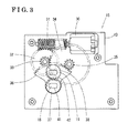
- Fig. 3 is an explanation diagram for an inner configuration of an actuator related to the embodiment of this disclosure.
- Fig. 1 is a side cross-sectional view of an engine room 2 indicating an entire configuration of a grille shutter 1 related to an embodiment of this disclosure.
- a radiator 3 for cooling an engine coolant is arranged so as to be attached to a vehicle body 4.
- a grille opening portion 6 is formed at a lower front of the radiator 3 in a vehicle front-rear direction.
- a base frame 7 is provided, and a first fin 11 is attached to the base frame 7 so as to be rotatable relative to a first rotational shaft 10 serving a rotational axis of the first fin 11, and a second fin 13 is attached to the base frame 7 so as to be rotatable relative to a second rotational shaft 12 provided in the vicinity of the first rotational shaft 10, the second rotational shaft 12 serving as a rotational axis of the second fin 13.
- the first fin 11 and the second fin 13 are operated so as to rotate symmetrically in a vertical direction of the vehicle.
- Fig. 2 is an exploded perspective view of an entire configuration of the grille shutter 1 related to the embodiment of this disclosure.
- an actuator attaching portion 14 is provided at an intermediate portion of the base frame 7, and an actuator 15 (e.g., an actuating device) is attached to the base frame 7 at the actuator attaching portion 14 so as to be integral thereto.
- a first pair of the first and second fins 11 and 13 is provided at the right side of the base frame 7, and a second pair of the first and second fins 11 and 13 is also provided at the left side of the base frame 7.
- the base frame 7 is formed so as to include a first fin shaft supporting portion 16 and a second fin shaft supporting portion 17 at a right end portion of the base frame 7 in a width direction thereof.
- a first output shaft 18 and a second output shaft 19 are provided at the actuator 15.
- a first end portion 21 of the first fin 11 is connected to and supported by the first output shaft 18, and a second end portion 22 of the first fin 11 is supported by the first fin shaft supporting portion 16.
- a first end portion 23 of the second fin 13 is connected to and supported by the second output shaft 19, and a second end portion 24 of the second fin 13 is supported by the second fin shaft supporting portion 17.
- Fig. 3 is an explanation diagram for an inner configuration of the actuator 15 related to the embodiment of this disclosure.
- a worm gear 31 is provided at an output shaft of a motor 30 (e.g., a driving source), and the worm gear 31 is meshing with a worm wheel 32.
- the worm wheel 32 and a first pinion gear 33 are integrally and coaxially formed, and the first pinion gear 33 is meshing with the gear 34.
- the gear 34 is formed integrally and coaxially with a second pinion gear 35, and the second pinion gear 35 is meshing with a sector gear 36 being rotatable relative to the first output shaft 18.
- the sector gear 36 is formed so as to be coaxially and integrally with a first output gear 37 (e.g., a first gear), and the first output gear 37 is meshing with a second output gear 38 (e.g., a second gear) being rotatable relative to the second output shaft 19.
- a first recessed portion 41 having two flat surfaces being parallel to each other, is formed.
- a first protruding portion having two flat surfaces being parallel to each other, is formed at the first end portion 21 of the first fin 11.
- the first fin 11 is supported by the actuator 15 in such a way that the protruding portion formed at the first end portion 21 of the first fin 11 is fitted to the first recessed portion 41 of the first output gear 37, so that the first fin 11 is integrally rotatable with the first output gear 37.
- Two of the second output gears 38 are provided in such a way that the worm wheel 32, the gear 34 and the sector gear 36 are sandwiched therebetween in the axial direction thereof, and a second recessed portion 42, having two flat surfaces being parallel to each other, is formed on a surface of each of the second output gear 38, and a second protruding portion, having two flat surfaces being parallel to each other, is formed at the first end portion 23 of the second fin 13.
- the second fin 13 is supported by the actuator 15 in such a way that the protruding portion formed at the first end portion 23 of the second fin 13 is fit to the second recessed portion 42 of the second output gear 38, so that the second fin 13 is integrally rotatable with the second output gear 38.
- the motor 30, the worm gear 31, the worm wheel 32, the first pinion gear 33, the gear 34, the second pinion gear 35, the sector gear 36, the first output gear 37 and the second output gear 38 are housed in the housing 43, thereby configuration the actuator 15.
- a driving force generated at the motor 30 is transmitted to the first output gear 37 via the worm gear 31, the worm wheel 32, the first pinion gear 33, the gear 34, the second pinion gear 35 and the sector gear 36, thereby rotating the first output gear 37.
- the driving force transmitted to the sector gear 36 is further transmitted to the second output gear 38 via the first output gear 37, thereby rotating the second output gear 38 in a direction opposite to the rotation of the first output gear 37.
- the first fin 11 and the second fin 13 are operated in synchronization with each other so as to open or close the grille opening portion 6 in a manner where a top end of the first fin 11 follows a locus 25 (e.g., a first locus) that is symmetrical to a locus 26 (e.g., a second locus) determined by a top end of the second fin 13.
- a locus 25 e.g., a first locus
- a locus 26 e.g., a second locus
- the first output shaft 18 is arranged on the first rotational shaft 10 of the first fin 11, and the second output shaft 19 rotated in the direction opposite to the rotation of the first output shaft 18 is arrange at the second rotational shaft 12 of the second fin 13.
- the first fin 11 and the second fin 13 may be directly attached to the actuator 15, accordingly, compared to a case in which a link mechanism is used, an area in which the components are moved in accordance with an slide movement of the link mechanism does not need to be considered. Further, in this configuration, a level of mountability of the grille shutter may be increased. Further, because the link mechanism is not provided, a number of components may be reduced.
- the motor 30 may be downsized by optimizing (e.g., minimizing) the output of the motor 30.
- the first fin 11, the second fin 13 and the actuator 15 may be combined so as to form an assembly, the assembly is attached to the base frame 7, thereby improving mountability to the vehicle.
- the first fin 11 and the second fin 13 are operated so as to rotate symmetrically in the vertical direction of the vehicle, the area defined by the locus 25 determined by the top end of the first fin 11 and the locus 26 determined by the top end of the second fin 13 may be reduced, and in a case where the first fin 11 and the second fin 13 are rotated so as to fully open the grille opening portion 6 and are arranged so as to face each other, an area occupied by the first fin 11 and the second fin 13 may be reduced, thereby the level of mountability may be increased.
- the first rotational shaft 10 may be arranged in the vicinity of the second rotational shaft 12, a level of processing accuracy of portions to which the shafts are attached may be increased, thereby improving the mountability.
- the first output shaft 18 is operated simultaneously with the second output shaft 19 in a structure where the first output gear 37 is meshing with the second output gear 38, the first fin 11 and the second fin 13 are firmly operated in synchronization with each other so as to open or close the grille opening portion 6.
- the second output shaft 19 may be rotated in a direction that is opposite to the rotation of the first output shaft 18 without providing an idler gear or the like, accordingly the force transmitting path may be simplified.
- the grille shutter 1 is configured by the two first fins 11 and the two second fins 13, and one of the first fins 11 and one of the second fins 13 are provided at the right of the actuator 15, and the other of the first fins 11 and the other of the second fins 13 are provided at the left of the actuator 15.
- the width of each of the first fin 11 and the second fin 13 may be set so as to correspond to a width of the grille opening portion 6, and levels of distortions on the first fin 11 and the second fin 13 caused by a load of wind pressure applied thereto may be reduced, thereby firmly operating the first fins 11 and the second fins 13 so as to open or close the grille opening portion 6.
- the first fin 11 and the second fin 13 provided at the right of the actuator 15 and the first fin 11 and the second fin 13 provided at the left of the actuator 15 may be operated by means of a single component (the actuator 15).
- an interlocking mechanism is provided at each of the first output shaft 18 and the second output shaft 19, however, the interlocking mechanism may be provided at each of the first rotational shaft 10 and the second rotational shaft 12.
- the first rotational shaft 10 is arranged so as to be parallel to the second rotational shaft 12, however, the first rotational shaft 10 may be arranged so as to have an angle relative to the second rotational shaft 12 if there is a limitation related to mountability or a limitation related to an exterior design.
- a planetary gear mechanism may be used for the interlocking mechanism provided at each of the first output shaft 18 and the second output shaft 19, thereby arranging the first rotational shaft 10 so as to be coaxial with the second rotational shaft 12.
- a coaxial type speed reducing mechanism including a harmonic drive gear or a planetary gear train may be used as the speed reducing mechanism.
- the motor may be arranged coaxially with the first output shaft 18.
- the size of the first fin 11 provided at the right of the actuator 15 may be different from the size of the first fin 11 provided at the left of the actuator 15, and the size of the second fin 13 provided at the right of the actuator 15 may be different from the size of the second fin 13 provided at the left of the actuator 15.
- the actuator 15 may be positioned at a right end or a left end of the grille opening portion 6, and one first fin 11 and one second fin 13 may be provided.
- the driving force from the motor 30 is transmitted to the second output gear 38 via the first output gear 37, and the driving force transmitted to the second output gear 38 is eventually supplied to the first and second output shafts 18 and 19, however, the driving force generated at the motor 30 may be directly transmitted to each of the first and second output shafts 18 and 19.
- the movable grille shutter for the vehicle includes a first fin 11 adapted to be provided at a grille opening portion 6 through which ambient air is taken in, a second fin 13 adapted to be provided at the grille opening portion 6 and be arranged so as to be parallel to the first fin 11, a first output shaft 18 arranged on a rotational axis of the first fin 11, a second output shaft 19 arranged on a rotational axis of the second fin 13 so as to rotate in a direction opposite to a rotation of the first output shaft 18, a driving source 30 for supplying a driving force to the first output shaft 18 and the second output shaft 19 and an actuator 15 for actuating the first fin 11 and the second fin 13 so as to open or close the grille opening portion 6.
- the first output shaft 18 is arranged on the first rotational shaft 10 of the first fin 11, and the second output shaft 19 rotated in the direction opposite to the rotation of the first output shaft 18 is arrange at the second rotational shaft 12 of the second fin 13.
- the first fin 11 and the second fin 13 may be directly attached to the actuator 15, accordingly, compared to a case in which a link mechanism is used, an area in which the components are moved in accordance with an slide movement of the link mechanism does not need to be considered. Further, in this configuration, a level of mountability of the grille shutter may be increased. Further, because the link mechanism is not provided, a number of components may be reduced.
- the motor 30 may be downsized by optimizing (e.g., minimizing) the output of the motor 30.
- the first fin 11, the second fin 13 and the actuator 15 may be combined so as to form an assembly, the assembly is attached to the base frame 7, thereby improving mountability to the vehicle.
- the first fin 11 and the second fin 13 are simultaneously moved in such a way that one end of the first fin 11 follows a first locus 25 and one end of the second fin 13 follows a second locus 26 that is symmetrical to the first locus 25, and when the first fin 11 and the second fin 13 are actuated so as to fully-open the grille opening portion 6, the first fin 11 and the second fin 13 are arranged in such a way that the first fin 11 faces the second fin 13.
- the first fin 11 and the second fin 13 are operated so as to rotate symmetrically in the vertical direction of the vehicle, the area defined by the locus 25 determined by the top end of the first fin 11 and the locus 26 determined by the top end of the second fin 13 may be reduced, and in a case where the first fin 11 and the second fin 13 are rotated so as to fully open the grille opening portion 6 and are arranged so as to face each other, an area occupied by the first fin 11 and the second fin 13 may be reduced, thereby the level of mountability may be increased.
- the first rotational shaft 10 may be arranged in the vicinity of the second rotational shaft 12, a level of processing accuracy of portions to which the shafts are attached may be increased, thereby improving the mountability.
- the first output shaft 18 includes a first output gear 37
- the second output shaft 19 includes a second output gear 38 that is meshing with the first output gear 37.
- the first output shaft 18 is operated simultaneously with the second output shaft 19 in a structure where the first output gear 37 is meshing with the second output gear 38, the first fin 11 and the second fin 13 are firmly operated in synchronization with each other so as to open or close the grille opening portion 6.
- the driving force from the motor 30 is transmitted to the first output shaft 18, and the driving force transmitted to the first output shaft 18 is further transmitted to the second output shaft 19.
- the second output shaft 19 may be rotated in a direction that is opposite to the rotation of the first output shaft 18 without providing an idler gear or the like, accordingly the force transmitting path may be simplified.
- the movable grille shutter further includes two of the first fins 11 and two of the second fins 13, wherein one of the first fins 11 is arranged on an axis of the first output shaft 18 on one side of the actuator 15 in an axial direction of the first output shaft 18, the other of the first fins 11 is arranged on the axis of the first output shaft 18 on the other side of the actuating device 15 in the axial direction of the first output shaft 18, one of the second fins 13 is arranged on an axis of the second output shaft 19 on one side of the actuating device 15 in an axial direction of the second output shaft 19, and the other of the second fins 13 is arranged on the axis of the second output shaft 19 on the other side of the actuating device 15 in the axial direction of the second output shaft 19.
- the grille shutter 1 is configured by the two first fins 11 and the two second fins 13, and one of the first fins 11 and one of the second fins 13 are provided at the right of the actuator 15, and the other of the first fins 11 and the other of the second fins 13 are provided at the left of the actuator 15.
- the width of each of the first fin 11 and the second fin 13 may be set so as to correspond to a width of the grille opening portion 6, and levels of distortions on the first fin 11 and the second fin 13 caused by a load of wind pressure applied thereto may be reduced, thereby firmly operating the first fins 11 and the second fins 13 so as to open or close the grille opening portion 6.
- the first fin 11 and the second fin 13 provided at the right of the actuator 15 and the first fin 11 and the second fin 13 provided at the left of the actuator 15 may be operated by means of a single component (the actuator 15).
- a first recessed portion 41 having two flat surfaces being parallel to each other is formed at an end of the first output gear 37
- a second recessed portion 42 having two flat surfaces being parallel to each other is formed at an end of the second output gear 38
- a first protruding portion having two flat surfaces being parallel to each other is formed at an first end portion 21 of the first fin 11
- a second protruding portion having two flat surfaces being parallel to each other is formed at an second end portion 23 of the second fin 13
- the first fin 11 is attached to the first output gear 37 so as to be integrally rotatably in a manner where the first recessed portion 41 is fitted to the first protruding portion
- the second fin 13 is attached to the second output gear 38 so as to be integrally rotatably in a manner where the second recessed portion 42 is fitted to the second protruding portion.
- the grille opening portion 6 includes a first opening portion adapted to be opened or closed by the first fin 11 and a second opening portion adapted to be opened or closed by the second fin 13.
- the first opening portion and the second opening portion are arranged in a vertical direction of the vehicle.
Landscapes
- Engineering & Computer Science (AREA)
- Chemical & Material Sciences (AREA)
- Combustion & Propulsion (AREA)
- Transportation (AREA)
- Mechanical Engineering (AREA)
- Cooling, Air Intake And Gas Exhaust, And Fuel Tank Arrangements In Propulsion Units (AREA)
- Air-Conditioning For Vehicles (AREA)
Applications Claiming Priority (1)
| Application Number | Priority Date | Filing Date | Title |
|---|---|---|---|
| JP2010070953A JP2011201439A (ja) | 2010-03-25 | 2010-03-25 | 車両用可動グリルシャッター |
Publications (2)
| Publication Number | Publication Date |
|---|---|
| EP2371603A1 true EP2371603A1 (fr) | 2011-10-05 |
| EP2371603B1 EP2371603B1 (fr) | 2012-11-28 |
Family
ID=44305464
Family Applications (1)
| Application Number | Title | Priority Date | Filing Date |
|---|---|---|---|
| EP11158520A Not-in-force EP2371603B1 (fr) | 2010-03-25 | 2011-03-16 | Obturateur de calandre amovible pour véhicule |
Country Status (4)
| Country | Link |
|---|---|
| US (1) | US20110232981A1 (fr) |
| EP (1) | EP2371603B1 (fr) |
| JP (1) | JP2011201439A (fr) |
| CN (1) | CN102198793A (fr) |
Cited By (7)
| Publication number | Priority date | Publication date | Assignee | Title |
|---|---|---|---|---|
| EP2641768A1 (fr) * | 2012-03-22 | 2013-09-25 | Aisin Seiki Kabushiki Kaisha | Dispositif d'obturation de gril |
| NL2008922C2 (nl) * | 2012-06-01 | 2013-12-04 | Mci Mirror Controls Int Nl Bv | Verstelinrichting, luchtinlaat en motorvoertuig. |
| WO2014150140A1 (fr) * | 2013-03-15 | 2014-09-25 | Srg Global, Inc. | Ensemble volet de calandre |
| WO2016097589A1 (fr) | 2014-12-16 | 2016-06-23 | Electricfil Automotive | Dispositif de commande de volets par un actionneur lineaire |
| WO2016097588A1 (fr) | 2014-12-16 | 2016-06-23 | Electricfil Automotive | Dispositif de commande pour des volets pivotant selon des axes non paralleles |
| EP2528774A4 (fr) * | 2010-01-26 | 2017-04-12 | LG Innotek Co., Ltd. | Actionneur d'écran pour phare dans un véhicule |
| FR3052712A1 (fr) * | 2016-06-16 | 2017-12-22 | Peugeot Citroen Automobiles Sa | Dispositif de regulation d’un flux d’air circulant au travers d’une ouverture menagee dans un pare-chocs de vehicule automobile |
Families Citing this family (31)
| Publication number | Priority date | Publication date | Assignee | Title |
|---|---|---|---|---|
| NL2007162C2 (nl) * | 2011-07-21 | 2013-01-22 | Mci Mirror Controls Int Nl Bv | Verstelinrichting met aandrijfeenheid; luchtinlaat met een dergelijke verstelinrichting; motorvoertuig met een dergelijke luchtinlaat. |
| FR2978087B1 (fr) * | 2011-07-21 | 2013-08-23 | Valeo Systemes Thermiques | Dispositif d'obturation d'orifice de face avant de vehicule automobile. |
| US20140199930A1 (en) * | 2011-08-20 | 2014-07-17 | National University Corporation Nagoya University | Vehicle grille |
| JP5884397B2 (ja) | 2011-10-17 | 2016-03-15 | アイシン精機株式会社 | グリルシャッタ装置 |
| NL2008990C2 (nl) | 2012-06-12 | 2013-12-16 | Mci Mirror Controls Int Nl Bv | Verstelinrichting en werkwijze voor het verstellen van afsluitelementen. |
| DE102012011594B4 (de) * | 2012-06-13 | 2016-09-22 | Decoma (Germany) Gmbh | Steuerbarer Lufteinlass für ein Kraftfahrzeug mit Zylinderlamellen |
| KR101863935B1 (ko) * | 2012-07-24 | 2018-06-01 | 현대모비스 주식회사 | 자동차의 에어플랩 장치 |
| US9657632B2 (en) * | 2012-08-01 | 2017-05-23 | GM Global Technology Operations LLC | Method and apparatus for remote torque control of an aerodynamic air shutter mechanism |
| KR101945747B1 (ko) * | 2012-09-10 | 2019-02-08 | 현대모비스 주식회사 | 차량용 에어 플랩 장치 및 그 페일 판정 방법 |
| KR101360441B1 (ko) * | 2012-10-31 | 2014-02-24 | 현대자동차주식회사 | 차량용 액티브 에어플랩 장치 |
| US9085232B2 (en) * | 2013-01-11 | 2015-07-21 | Ford Global Technologies, Llc | Vehicle grille close-out assembly |
| US9533565B2 (en) | 2013-02-05 | 2017-01-03 | Montaplast of North America, Inc. | Active grille shutter assembly |
| US20140273807A1 (en) * | 2013-03-15 | 2014-09-18 | Srg Global , Inc. | Grille Shutter Assembly |
| JP5915582B2 (ja) * | 2013-03-29 | 2016-05-11 | マツダ株式会社 | 車両のグリルシャッタ構造 |
| GB2518829A (en) * | 2013-10-01 | 2015-04-08 | Johnson Electric Sa | Actuator and Grille Incorporating the Actuator |
| KR101936726B1 (ko) | 2013-12-17 | 2019-01-09 | 한온시스템 주식회사 | 액티브 에어 플랩 |
| CA2943374C (fr) * | 2014-03-20 | 2019-10-22 | Magna International Inc. | Aube creuse avec structure |
| KR101532976B1 (ko) * | 2014-09-01 | 2015-07-01 | 현대모비스 주식회사 | 차량용 에어 플랩 장치 |
| JP6155249B2 (ja) * | 2014-12-26 | 2017-06-28 | 株式会社ファルテック | グリルシャッタモジュール |
| KR101714220B1 (ko) | 2015-09-15 | 2017-03-08 | 현대자동차주식회사 | 액티브 에어 플랩 및 액티브 에어 플랩 조립체 |
| JP6618774B2 (ja) | 2015-11-09 | 2019-12-11 | アイシン精機株式会社 | 車両用ラジエータ装置 |
| US10100707B2 (en) | 2016-02-29 | 2018-10-16 | Montaplast of North America, Inc. | Active grille shutter and shutter subassembly for use with active grill shutters |
| FR3067296B1 (fr) * | 2017-06-13 | 2020-01-10 | Compagnie Plastic Omnium | Systeme aerodynamique actif avec actionneur deporte |
| US11512623B2 (en) | 2017-07-17 | 2022-11-29 | Kohler Co. | Apparatus for controlling cooling airflow to an intenral combustion engine, and engines and methods utilizing the same |
| JP6756313B2 (ja) * | 2017-07-25 | 2020-09-16 | 株式会社デンソー | シャッター装置 |
| JP7106864B2 (ja) * | 2018-01-10 | 2022-07-27 | 株式会社アイシン | シャッタ装置 |
| DE102019113165A1 (de) * | 2019-05-17 | 2020-11-19 | Bayerische Motoren Werke Aktiengesellschaft | Lufteinlassanordnung |
| JP7388030B2 (ja) * | 2019-07-26 | 2023-11-29 | 株式会社デンソー | 車両のシャッタ装置 |
| CN110450625A (zh) * | 2019-09-17 | 2019-11-15 | 延锋安道拓方德电机有限公司 | 汽车及其主动式进气格栅执行器 |
| DE102020108906A1 (de) * | 2020-03-31 | 2021-09-30 | Röchling Automotive SE & Co. KG | Luftklappenanordnung mit asynchron beweglichen Luftklappenfeldern |
| KR20220081456A (ko) * | 2020-12-08 | 2022-06-16 | 현대모비스 주식회사 | 차량용 액티브 에어 플랩 장치 |
Citations (5)
| Publication number | Priority date | Publication date | Assignee | Title |
|---|---|---|---|---|
| DE397239C (de) * | 1924-06-18 | Audiwerke A G | Kuehler fuer Motorfahrzeuge | |
| JPS58139519U (ja) | 1982-03-17 | 1983-09-20 | 三菱自動車工業株式会社 | グリル開閉装置 |
| DE10307632A1 (de) * | 2003-02-22 | 2004-09-02 | Adam Opel Ag | Vorrichtung zur Regelung des Kühlluftdurchsatzes für einen Verbrennungsmotor eines Kraftfahrzeuges |
| DE602004007338T2 (de) * | 2003-10-06 | 2008-03-06 | Peugeot Citroën Automobiles S.A. | Vorrichtung zur Regulierung eines insbesondere unter die Motorhaube eines Kraftfahrzeuges eintretenden Luftstromes |
| EP2325035A1 (fr) * | 2009-11-19 | 2011-05-25 | Aisin Seiki Kabushiki Kaisha | Mécanisme de contrôle de calandre pour véhicule |
Family Cites Families (2)
| Publication number | Priority date | Publication date | Assignee | Title |
|---|---|---|---|---|
| US5957184A (en) * | 1998-03-16 | 1999-09-28 | Gross; Fred J. | Tilter mechanism for horizontal blind |
| JP4438757B2 (ja) * | 2006-02-08 | 2010-03-24 | トヨタ自動車株式会社 | 車両用冷却装置 |
-
2010
- 2010-03-25 JP JP2010070953A patent/JP2011201439A/ja active Pending
-
2011
- 2011-03-16 EP EP11158520A patent/EP2371603B1/fr not_active Not-in-force
- 2011-03-22 US US13/064,375 patent/US20110232981A1/en not_active Abandoned
- 2011-03-23 CN CN201110076356XA patent/CN102198793A/zh active Pending
Patent Citations (5)
| Publication number | Priority date | Publication date | Assignee | Title |
|---|---|---|---|---|
| DE397239C (de) * | 1924-06-18 | Audiwerke A G | Kuehler fuer Motorfahrzeuge | |
| JPS58139519U (ja) | 1982-03-17 | 1983-09-20 | 三菱自動車工業株式会社 | グリル開閉装置 |
| DE10307632A1 (de) * | 2003-02-22 | 2004-09-02 | Adam Opel Ag | Vorrichtung zur Regelung des Kühlluftdurchsatzes für einen Verbrennungsmotor eines Kraftfahrzeuges |
| DE602004007338T2 (de) * | 2003-10-06 | 2008-03-06 | Peugeot Citroën Automobiles S.A. | Vorrichtung zur Regulierung eines insbesondere unter die Motorhaube eines Kraftfahrzeuges eintretenden Luftstromes |
| EP2325035A1 (fr) * | 2009-11-19 | 2011-05-25 | Aisin Seiki Kabushiki Kaisha | Mécanisme de contrôle de calandre pour véhicule |
Cited By (11)
| Publication number | Priority date | Publication date | Assignee | Title |
|---|---|---|---|---|
| EP2528774A4 (fr) * | 2010-01-26 | 2017-04-12 | LG Innotek Co., Ltd. | Actionneur d'écran pour phare dans un véhicule |
| EP2641768A1 (fr) * | 2012-03-22 | 2013-09-25 | Aisin Seiki Kabushiki Kaisha | Dispositif d'obturation de gril |
| US8960343B2 (en) | 2012-03-22 | 2015-02-24 | Aisin Seiki Kabushiki Kaisha | Grill shutter device |
| NL2008922C2 (nl) * | 2012-06-01 | 2013-12-04 | Mci Mirror Controls Int Nl Bv | Verstelinrichting, luchtinlaat en motorvoertuig. |
| WO2013180569A1 (fr) * | 2012-06-01 | 2013-12-05 | Mci (Mirror Controls International) Netherlands B.V. | Dispositif de réglage, entrée d'air, et véhicule à moteur |
| US9150097B2 (en) | 2012-06-01 | 2015-10-06 | Mci (Mirror Controls International) Netherlands B.V. | Adjustment device, air inlet, and motor vehicle |
| WO2014150140A1 (fr) * | 2013-03-15 | 2014-09-25 | Srg Global, Inc. | Ensemble volet de calandre |
| US10029558B2 (en) | 2013-03-15 | 2018-07-24 | Srg Global, Inc. | Grille shutter assembly |
| WO2016097589A1 (fr) | 2014-12-16 | 2016-06-23 | Electricfil Automotive | Dispositif de commande de volets par un actionneur lineaire |
| WO2016097588A1 (fr) | 2014-12-16 | 2016-06-23 | Electricfil Automotive | Dispositif de commande pour des volets pivotant selon des axes non paralleles |
| FR3052712A1 (fr) * | 2016-06-16 | 2017-12-22 | Peugeot Citroen Automobiles Sa | Dispositif de regulation d’un flux d’air circulant au travers d’une ouverture menagee dans un pare-chocs de vehicule automobile |
Also Published As
| Publication number | Publication date |
|---|---|
| CN102198793A (zh) | 2011-09-28 |
| JP2011201439A (ja) | 2011-10-13 |
| EP2371603B1 (fr) | 2012-11-28 |
| US20110232981A1 (en) | 2011-09-29 |
Similar Documents
| Publication | Publication Date | Title |
|---|---|---|
| EP2371603A1 (fr) | Obturateur de calandre amovible pour véhicule | |
| US9254742B2 (en) | Grille shutter | |
| JP5136122B2 (ja) | ルーバ装置 | |
| US8561739B2 (en) | Movable grille shutter for vehicle | |
| EP2407333B1 (fr) | Obturateur de calandre amovible pour véhicule | |
| US8944487B2 (en) | Door opening/closing apparatus | |
| JP6155483B2 (ja) | パワードア開閉装置 | |
| EP2371602A1 (fr) | Obturateur de calandre amovible pour véhicule | |
| EP2799270A1 (fr) | Dispositif obturateur | |
| EP2650159A1 (fr) | Dispositif de commande d'ouverture/fermeture de volet de grille | |
| KR101272912B1 (ko) | 액티브 에어 플랩 장치 | |
| WO2016006141A1 (fr) | Dispositif d'ouverture et de fermeture de porte motorisé et automobile comportant un dispositif d'ouverture et de fermeture | |
| JP5877558B2 (ja) | ヘッドアップディスプレイ装置 | |
| JP6189194B2 (ja) | グリルシャッター装置 | |
| JP6179270B2 (ja) | 車両用ドア開閉装置 | |
| US10416449B2 (en) | Display apparatus having moving mechanism | |
| WO2016147372A1 (fr) | Dispositif d'affichage | |
| CN112659854A (zh) | 空调用吹出口装置 | |
| KR101393972B1 (ko) | 차량용 액티브 에어플랩 장치 | |
| JP5061914B2 (ja) | スイングレジスタ | |
| US20240159098A1 (en) | Integrated Operating Apparatus for Different Type Gates | |
| US20230322060A1 (en) | Sunroof structure of vehicle | |
| JP2006034366A (ja) | 便座装置 | |
| KR100853667B1 (ko) | 가스연료차량의 공기량 혼합장치 | |
| CN116262438A (zh) | 车辆用活动风门片装置 |
Legal Events
| Date | Code | Title | Description |
|---|---|---|---|
| PUAI | Public reference made under article 153(3) epc to a published international application that has entered the european phase |
Free format text: ORIGINAL CODE: 0009012 |
|
| AK | Designated contracting states |
Kind code of ref document: A1 Designated state(s): AL AT BE BG CH CY CZ DE DK EE ES FI FR GB GR HR HU IE IS IT LI LT LU LV MC MK MT NL NO PL PT RO RS SE SI SK SM TR |
|
| AX | Request for extension of the european patent |
Extension state: BA ME |
|
| 17P | Request for examination filed |
Effective date: 20111129 |
|
| 17Q | First examination report despatched |
Effective date: 20120104 |
|
| GRAP | Despatch of communication of intention to grant a patent |
Free format text: ORIGINAL CODE: EPIDOSNIGR1 |
|
| RIN1 | Information on inventor provided before grant (corrected) |
Inventor name: ASANO, YOSHIMASA C/O AISIN SEIKI KABUSHIKI KAISHA Inventor name: HORI, KENJI C/O AISIN SEIKI KABUSHIKI KAISHA Inventor name: NISHIKAWA, MASUMI C/O AISIN SEIKI KABUSHIKI KAISHA |
|
| GRAS | Grant fee paid |
Free format text: ORIGINAL CODE: EPIDOSNIGR3 |
|
| GRAA | (expected) grant |
Free format text: ORIGINAL CODE: 0009210 |
|
| STAA | Information on the status of an ep patent application or granted ep patent |
Free format text: STATUS: THE PATENT HAS BEEN GRANTED |
|
| AK | Designated contracting states |
Kind code of ref document: B1 Designated state(s): AL AT BE BG CH CY CZ DE DK EE ES FI FR GB GR HR HU IE IS IT LI LT LU LV MC MK MT NL NO PL PT RO RS SE SI SK SM TR |
|
| REG | Reference to a national code |
Ref country code: GB Ref legal event code: FG4D |
|
| REG | Reference to a national code |
Ref country code: CH Ref legal event code: EP |
|
| REG | Reference to a national code |
Ref country code: AT Ref legal event code: REF Ref document number: 585964 Country of ref document: AT Kind code of ref document: T Effective date: 20121215 |
|
| REG | Reference to a national code |
Ref country code: IE Ref legal event code: FG4D |
|
| REG | Reference to a national code |
Ref country code: DE Ref legal event code: R096 Ref document number: 602011000506 Country of ref document: DE Effective date: 20130124 |
|
| REG | Reference to a national code |
Ref country code: AT Ref legal event code: MK05 Ref document number: 585964 Country of ref document: AT Kind code of ref document: T Effective date: 20121128 |
|
| REG | Reference to a national code |
Ref country code: NL Ref legal event code: VDEP Effective date: 20121128 |
|
| REG | Reference to a national code |
Ref country code: LT Ref legal event code: MG4D |
|
| PG25 | Lapsed in a contracting state [announced via postgrant information from national office to epo] |
Ref country code: SE Free format text: LAPSE BECAUSE OF FAILURE TO SUBMIT A TRANSLATION OF THE DESCRIPTION OR TO PAY THE FEE WITHIN THE PRESCRIBED TIME-LIMIT Effective date: 20121128 Ref country code: LT Free format text: LAPSE BECAUSE OF FAILURE TO SUBMIT A TRANSLATION OF THE DESCRIPTION OR TO PAY THE FEE WITHIN THE PRESCRIBED TIME-LIMIT Effective date: 20121128 Ref country code: NO Free format text: LAPSE BECAUSE OF FAILURE TO SUBMIT A TRANSLATION OF THE DESCRIPTION OR TO PAY THE FEE WITHIN THE PRESCRIBED TIME-LIMIT Effective date: 20130228 Ref country code: ES Free format text: LAPSE BECAUSE OF FAILURE TO SUBMIT A TRANSLATION OF THE DESCRIPTION OR TO PAY THE FEE WITHIN THE PRESCRIBED TIME-LIMIT Effective date: 20130311 Ref country code: FI Free format text: LAPSE BECAUSE OF FAILURE TO SUBMIT A TRANSLATION OF THE DESCRIPTION OR TO PAY THE FEE WITHIN THE PRESCRIBED TIME-LIMIT Effective date: 20121128 |
|
| PG25 | Lapsed in a contracting state [announced via postgrant information from national office to epo] |
Ref country code: SI Free format text: LAPSE BECAUSE OF FAILURE TO SUBMIT A TRANSLATION OF THE DESCRIPTION OR TO PAY THE FEE WITHIN THE PRESCRIBED TIME-LIMIT Effective date: 20121128 Ref country code: PT Free format text: LAPSE BECAUSE OF FAILURE TO SUBMIT A TRANSLATION OF THE DESCRIPTION OR TO PAY THE FEE WITHIN THE PRESCRIBED TIME-LIMIT Effective date: 20130328 Ref country code: PL Free format text: LAPSE BECAUSE OF FAILURE TO SUBMIT A TRANSLATION OF THE DESCRIPTION OR TO PAY THE FEE WITHIN THE PRESCRIBED TIME-LIMIT Effective date: 20121128 Ref country code: LV Free format text: LAPSE BECAUSE OF FAILURE TO SUBMIT A TRANSLATION OF THE DESCRIPTION OR TO PAY THE FEE WITHIN THE PRESCRIBED TIME-LIMIT Effective date: 20121128 Ref country code: BE Free format text: LAPSE BECAUSE OF FAILURE TO SUBMIT A TRANSLATION OF THE DESCRIPTION OR TO PAY THE FEE WITHIN THE PRESCRIBED TIME-LIMIT Effective date: 20121128 Ref country code: GR Free format text: LAPSE BECAUSE OF FAILURE TO SUBMIT A TRANSLATION OF THE DESCRIPTION OR TO PAY THE FEE WITHIN THE PRESCRIBED TIME-LIMIT Effective date: 20130301 |
|
| PG25 | Lapsed in a contracting state [announced via postgrant information from national office to epo] |
Ref country code: AT Free format text: LAPSE BECAUSE OF FAILURE TO SUBMIT A TRANSLATION OF THE DESCRIPTION OR TO PAY THE FEE WITHIN THE PRESCRIBED TIME-LIMIT Effective date: 20121128 |
|
| PG25 | Lapsed in a contracting state [announced via postgrant information from national office to epo] |
Ref country code: SK Free format text: LAPSE BECAUSE OF FAILURE TO SUBMIT A TRANSLATION OF THE DESCRIPTION OR TO PAY THE FEE WITHIN THE PRESCRIBED TIME-LIMIT Effective date: 20121128 Ref country code: DK Free format text: LAPSE BECAUSE OF FAILURE TO SUBMIT A TRANSLATION OF THE DESCRIPTION OR TO PAY THE FEE WITHIN THE PRESCRIBED TIME-LIMIT Effective date: 20121128 Ref country code: EE Free format text: LAPSE BECAUSE OF FAILURE TO SUBMIT A TRANSLATION OF THE DESCRIPTION OR TO PAY THE FEE WITHIN THE PRESCRIBED TIME-LIMIT Effective date: 20121128 Ref country code: RS Free format text: LAPSE BECAUSE OF FAILURE TO SUBMIT A TRANSLATION OF THE DESCRIPTION OR TO PAY THE FEE WITHIN THE PRESCRIBED TIME-LIMIT Effective date: 20121128 Ref country code: BG Free format text: LAPSE BECAUSE OF FAILURE TO SUBMIT A TRANSLATION OF THE DESCRIPTION OR TO PAY THE FEE WITHIN THE PRESCRIBED TIME-LIMIT Effective date: 20130228 Ref country code: CZ Free format text: LAPSE BECAUSE OF FAILURE TO SUBMIT A TRANSLATION OF THE DESCRIPTION OR TO PAY THE FEE WITHIN THE PRESCRIBED TIME-LIMIT Effective date: 20121128 |
|
| PG25 | Lapsed in a contracting state [announced via postgrant information from national office to epo] |
Ref country code: RO Free format text: LAPSE BECAUSE OF FAILURE TO SUBMIT A TRANSLATION OF THE DESCRIPTION OR TO PAY THE FEE WITHIN THE PRESCRIBED TIME-LIMIT Effective date: 20121128 Ref country code: NL Free format text: LAPSE BECAUSE OF FAILURE TO SUBMIT A TRANSLATION OF THE DESCRIPTION OR TO PAY THE FEE WITHIN THE PRESCRIBED TIME-LIMIT Effective date: 20121128 Ref country code: IT Free format text: LAPSE BECAUSE OF FAILURE TO SUBMIT A TRANSLATION OF THE DESCRIPTION OR TO PAY THE FEE WITHIN THE PRESCRIBED TIME-LIMIT Effective date: 20121128 |
|
| PLBE | No opposition filed within time limit |
Free format text: ORIGINAL CODE: 0009261 |
|
| STAA | Information on the status of an ep patent application or granted ep patent |
Free format text: STATUS: NO OPPOSITION FILED WITHIN TIME LIMIT |
|
| PG25 | Lapsed in a contracting state [announced via postgrant information from national office to epo] |
Ref country code: MC Free format text: LAPSE BECAUSE OF NON-PAYMENT OF DUE FEES Effective date: 20130331 |
|
| 26N | No opposition filed |
Effective date: 20130829 |
|
| PG25 | Lapsed in a contracting state [announced via postgrant information from national office to epo] |
Ref country code: CY Free format text: LAPSE BECAUSE OF FAILURE TO SUBMIT A TRANSLATION OF THE DESCRIPTION OR TO PAY THE FEE WITHIN THE PRESCRIBED TIME-LIMIT Effective date: 20121128 |
|
| REG | Reference to a national code |
Ref country code: DE Ref legal event code: R097 Ref document number: 602011000506 Country of ref document: DE Effective date: 20130829 |
|
| REG | Reference to a national code |
Ref country code: FR Ref legal event code: ST Effective date: 20131129 |
|
| REG | Reference to a national code |
Ref country code: IE Ref legal event code: MM4A |
|
| REG | Reference to a national code |
Ref country code: DE Ref legal event code: R119 Ref document number: 602011000506 Country of ref document: DE Effective date: 20131001 |
|
| PG25 | Lapsed in a contracting state [announced via postgrant information from national office to epo] |
Ref country code: AL Free format text: LAPSE BECAUSE OF FAILURE TO SUBMIT A TRANSLATION OF THE DESCRIPTION OR TO PAY THE FEE WITHIN THE PRESCRIBED TIME-LIMIT Effective date: 20121128 Ref country code: FR Free format text: LAPSE BECAUSE OF NON-PAYMENT OF DUE FEES Effective date: 20130402 Ref country code: DE Free format text: LAPSE BECAUSE OF NON-PAYMENT OF DUE FEES Effective date: 20131001 Ref country code: IE Free format text: LAPSE BECAUSE OF NON-PAYMENT OF DUE FEES Effective date: 20130316 Ref country code: HR Free format text: LAPSE BECAUSE OF FAILURE TO SUBMIT A TRANSLATION OF THE DESCRIPTION OR TO PAY THE FEE WITHIN THE PRESCRIBED TIME-LIMIT Effective date: 20130731 |
|
| PG25 | Lapsed in a contracting state [announced via postgrant information from national office to epo] |
Ref country code: MT Free format text: LAPSE BECAUSE OF FAILURE TO SUBMIT A TRANSLATION OF THE DESCRIPTION OR TO PAY THE FEE WITHIN THE PRESCRIBED TIME-LIMIT Effective date: 20121128 |
|
| REG | Reference to a national code |
Ref country code: CH Ref legal event code: PL |
|
| PG25 | Lapsed in a contracting state [announced via postgrant information from national office to epo] |
Ref country code: LI Free format text: LAPSE BECAUSE OF NON-PAYMENT OF DUE FEES Effective date: 20140331 Ref country code: CH Free format text: LAPSE BECAUSE OF NON-PAYMENT OF DUE FEES Effective date: 20140331 |
|
| PG25 | Lapsed in a contracting state [announced via postgrant information from national office to epo] |
Ref country code: SM Free format text: LAPSE BECAUSE OF FAILURE TO SUBMIT A TRANSLATION OF THE DESCRIPTION OR TO PAY THE FEE WITHIN THE PRESCRIBED TIME-LIMIT Effective date: 20121128 |
|
| PG25 | Lapsed in a contracting state [announced via postgrant information from national office to epo] |
Ref country code: TR Free format text: LAPSE BECAUSE OF FAILURE TO SUBMIT A TRANSLATION OF THE DESCRIPTION OR TO PAY THE FEE WITHIN THE PRESCRIBED TIME-LIMIT Effective date: 20121128 |
|
| PG25 | Lapsed in a contracting state [announced via postgrant information from national office to epo] |
Ref country code: HU Free format text: LAPSE BECAUSE OF FAILURE TO SUBMIT A TRANSLATION OF THE DESCRIPTION OR TO PAY THE FEE WITHIN THE PRESCRIBED TIME-LIMIT; INVALID AB INITIO Effective date: 20110316 Ref country code: MK Free format text: LAPSE BECAUSE OF FAILURE TO SUBMIT A TRANSLATION OF THE DESCRIPTION OR TO PAY THE FEE WITHIN THE PRESCRIBED TIME-LIMIT Effective date: 20121128 Ref country code: LU Free format text: LAPSE BECAUSE OF NON-PAYMENT OF DUE FEES Effective date: 20130316 |
|
| GBPC | Gb: european patent ceased through non-payment of renewal fee |
Effective date: 20150316 |
|
| PG25 | Lapsed in a contracting state [announced via postgrant information from national office to epo] |
Ref country code: GB Free format text: LAPSE BECAUSE OF NON-PAYMENT OF DUE FEES Effective date: 20150316 |
|
| PG25 | Lapsed in a contracting state [announced via postgrant information from national office to epo] |
Ref country code: IS Free format text: LAPSE BECAUSE OF FAILURE TO SUBMIT A TRANSLATION OF THE DESCRIPTION OR TO PAY THE FEE WITHIN THE PRESCRIBED TIME-LIMIT Effective date: 20121128 |