EP2471635A1 - Verfahren zum Aufschneiden von Lebensmitteln - Google Patents
Verfahren zum Aufschneiden von Lebensmitteln Download PDFInfo
- Publication number
- EP2471635A1 EP2471635A1 EP20120001764 EP12001764A EP2471635A1 EP 2471635 A1 EP2471635 A1 EP 2471635A1 EP 20120001764 EP20120001764 EP 20120001764 EP 12001764 A EP12001764 A EP 12001764A EP 2471635 A1 EP2471635 A1 EP 2471635A1
- Authority
- EP
- European Patent Office
- Prior art keywords
- knife
- cutting
- food
- bar
- food bar
- Prior art date
- Legal status (The legal status is an assumption and is not a legal conclusion. Google has not performed a legal analysis and makes no representation as to the accuracy of the status listed.)
- Granted
Links
Images


Classifications
-
- B—PERFORMING OPERATIONS; TRANSPORTING
- B26—HAND CUTTING TOOLS; CUTTING; SEVERING
- B26D—CUTTING; DETAILS COMMON TO MACHINES FOR PERFORATING, PUNCHING, CUTTING-OUT, STAMPING-OUT OR SEVERING
- B26D1/00—Cutting through work characterised by the nature or movement of the cutting member or particular materials not otherwise provided for; Apparatus or machines therefor; Cutting members therefor
- B26D1/0006—Cutting members therefor
-
- B—PERFORMING OPERATIONS; TRANSPORTING
- B26—HAND CUTTING TOOLS; CUTTING; SEVERING
- B26D—CUTTING; DETAILS COMMON TO MACHINES FOR PERFORATING, PUNCHING, CUTTING-OUT, STAMPING-OUT OR SEVERING
- B26D5/00—Arrangements for operating and controlling machines or devices for cutting, cutting-out, stamping-out, punching, perforating, or severing by means other than cutting
- B26D5/007—Control means comprising cameras, vision or image processing systems
-
- B—PERFORMING OPERATIONS; TRANSPORTING
- B26—HAND CUTTING TOOLS; CUTTING; SEVERING
- B26D—CUTTING; DETAILS COMMON TO MACHINES FOR PERFORATING, PUNCHING, CUTTING-OUT, STAMPING-OUT OR SEVERING
- B26D7/00—Details of apparatus for cutting, cutting-out, stamping-out, punching, perforating, or severing by means other than cutting
- B26D7/0006—Means for guiding the cutter
-
- B—PERFORMING OPERATIONS; TRANSPORTING
- B26—HAND CUTTING TOOLS; CUTTING; SEVERING
- B26D—CUTTING; DETAILS COMMON TO MACHINES FOR PERFORATING, PUNCHING, CUTTING-OUT, STAMPING-OUT OR SEVERING
- B26D7/00—Details of apparatus for cutting, cutting-out, stamping-out, punching, perforating, or severing by means other than cutting
- B26D7/08—Means for treating work or cutting member to facilitate cutting
-
- B—PERFORMING OPERATIONS; TRANSPORTING
- B26—HAND CUTTING TOOLS; CUTTING; SEVERING
- B26D—CUTTING; DETAILS COMMON TO MACHINES FOR PERFORATING, PUNCHING, CUTTING-OUT, STAMPING-OUT OR SEVERING
- B26D7/00—Details of apparatus for cutting, cutting-out, stamping-out, punching, perforating, or severing by means other than cutting
- B26D7/26—Means for mounting or adjusting the cutting member; Means for adjusting the stroke of the cutting member
- B26D7/2628—Means for adjusting the position of the cutting member
- B26D7/2635—Means for adjusting the position of the cutting member for circular cutters
-
- B—PERFORMING OPERATIONS; TRANSPORTING
- B26—HAND CUTTING TOOLS; CUTTING; SEVERING
- B26D—CUTTING; DETAILS COMMON TO MACHINES FOR PERFORATING, PUNCHING, CUTTING-OUT, STAMPING-OUT OR SEVERING
- B26D2210/00—Machines or methods used for cutting special materials
- B26D2210/02—Machines or methods used for cutting special materials for cutting food products, e.g. food slicers
- B26D2210/08—Idle cutting
-
- B—PERFORMING OPERATIONS; TRANSPORTING
- B26—HAND CUTTING TOOLS; CUTTING; SEVERING
- B26D—CUTTING; DETAILS COMMON TO MACHINES FOR PERFORATING, PUNCHING, CUTTING-OUT, STAMPING-OUT OR SEVERING
- B26D5/00—Arrangements for operating and controlling machines or devices for cutting, cutting-out, stamping-out, punching, perforating, or severing by means other than cutting
- B26D5/20—Arrangements for operating and controlling machines or devices for cutting, cutting-out, stamping-out, punching, perforating, or severing by means other than cutting with interrelated action between the cutting member and work feed
- B26D5/30—Arrangements for operating and controlling machines or devices for cutting, cutting-out, stamping-out, punching, perforating, or severing by means other than cutting with interrelated action between the cutting member and work feed having the cutting member controlled by scanning a record carrier
- B26D5/32—Arrangements for operating and controlling machines or devices for cutting, cutting-out, stamping-out, punching, perforating, or severing by means other than cutting with interrelated action between the cutting member and work feed having the cutting member controlled by scanning a record carrier with the record carrier formed by the work itself
-
- B—PERFORMING OPERATIONS; TRANSPORTING
- B26—HAND CUTTING TOOLS; CUTTING; SEVERING
- B26D—CUTTING; DETAILS COMMON TO MACHINES FOR PERFORATING, PUNCHING, CUTTING-OUT, STAMPING-OUT OR SEVERING
- B26D5/00—Arrangements for operating and controlling machines or devices for cutting, cutting-out, stamping-out, punching, perforating, or severing by means other than cutting
- B26D5/20—Arrangements for operating and controlling machines or devices for cutting, cutting-out, stamping-out, punching, perforating, or severing by means other than cutting with interrelated action between the cutting member and work feed
- B26D5/30—Arrangements for operating and controlling machines or devices for cutting, cutting-out, stamping-out, punching, perforating, or severing by means other than cutting with interrelated action between the cutting member and work feed having the cutting member controlled by scanning a record carrier
- B26D5/34—Arrangements for operating and controlling machines or devices for cutting, cutting-out, stamping-out, punching, perforating, or severing by means other than cutting with interrelated action between the cutting member and work feed having the cutting member controlled by scanning a record carrier scanning being effected by a photosensitive device
-
- B—PERFORMING OPERATIONS; TRANSPORTING
- B26—HAND CUTTING TOOLS; CUTTING; SEVERING
- B26D—CUTTING; DETAILS COMMON TO MACHINES FOR PERFORATING, PUNCHING, CUTTING-OUT, STAMPING-OUT OR SEVERING
- B26D7/00—Details of apparatus for cutting, cutting-out, stamping-out, punching, perforating, or severing by means other than cutting
- B26D7/06—Arrangements for feeding or delivering work of other than sheet, web, or filamentary form
- B26D7/0625—Arrangements for feeding or delivering work of other than sheet, web, or filamentary form by endless conveyors, e.g. belts
-
- B—PERFORMING OPERATIONS; TRANSPORTING
- B26—HAND CUTTING TOOLS; CUTTING; SEVERING
- B26D—CUTTING; DETAILS COMMON TO MACHINES FOR PERFORATING, PUNCHING, CUTTING-OUT, STAMPING-OUT OR SEVERING
- B26D7/00—Details of apparatus for cutting, cutting-out, stamping-out, punching, perforating, or severing by means other than cutting
- B26D7/08—Means for treating work or cutting member to facilitate cutting
- B26D7/12—Means for treating work or cutting member to facilitate cutting by sharpening the cutting member
-
- B—PERFORMING OPERATIONS; TRANSPORTING
- B26—HAND CUTTING TOOLS; CUTTING; SEVERING
- B26D—CUTTING; DETAILS COMMON TO MACHINES FOR PERFORATING, PUNCHING, CUTTING-OUT, STAMPING-OUT OR SEVERING
- B26D7/00—Details of apparatus for cutting, cutting-out, stamping-out, punching, perforating, or severing by means other than cutting
- B26D7/27—Means for performing other operations combined with cutting
- B26D7/30—Means for performing other operations combined with cutting for weighing cut product
-
- Y—GENERAL TAGGING OF NEW TECHNOLOGICAL DEVELOPMENTS; GENERAL TAGGING OF CROSS-SECTIONAL TECHNOLOGIES SPANNING OVER SEVERAL SECTIONS OF THE IPC; TECHNICAL SUBJECTS COVERED BY FORMER USPC CROSS-REFERENCE ART COLLECTIONS [XRACs] AND DIGESTS
- Y10—TECHNICAL SUBJECTS COVERED BY FORMER USPC
- Y10T—TECHNICAL SUBJECTS COVERED BY FORMER US CLASSIFICATION
- Y10T83/00—Cutting
- Y10T83/04—Processes
- Y10T83/0448—With subsequent handling [i.e., of product]
-
- Y—GENERAL TAGGING OF NEW TECHNOLOGICAL DEVELOPMENTS; GENERAL TAGGING OF CROSS-SECTIONAL TECHNOLOGIES SPANNING OVER SEVERAL SECTIONS OF THE IPC; TECHNICAL SUBJECTS COVERED BY FORMER USPC CROSS-REFERENCE ART COLLECTIONS [XRACs] AND DIGESTS
- Y10—TECHNICAL SUBJECTS COVERED BY FORMER USPC
- Y10T—TECHNICAL SUBJECTS COVERED BY FORMER US CLASSIFICATION
- Y10T83/00—Cutting
- Y10T83/929—Tool or tool with support
Definitions
- the present invention relates to a method for separating food slices from at least one food bar with a rotating knife, in which the food bar with at least one transport in the direction of the knife is transportable. Furthermore, the present invention relates to a device for separating food slices of at least one food bar with a rotating knife, bel the food bar with at least one transport in the direction of the knife is transportable, and a knife for slicing food.
- the regulation of the slice thickness is performed via the feed rate of the food bar.
- the cut slices are usually combined into portions with constant number of plates and packaged.
- the prior art methods and devices have the disadvantage that problems occur completely unprepared or that changes to the product can not be adequately reacted.
- the object is achieved with a method for slicing a food bar with a device comprising a rotating knife and at least one means of transport in which the food bar is inserted into a feed path and transported by the transport in the direction of the knife and thereby cut, the device at least one vibration sensor and / or at least one product sensor, which determines at least one parameter of the food bar is assigned, the signal is used for monitoring and / or adjustment of the device or the cutting process.
- rod-shaped or otherwise shaped food such as sausage, cheese, ham or the like are cut into slices with a very high cutting performance.
- the food bar by means of a regulated drive by a stationary cutting plane in which the cut is made by a fast-moving, usually rotating knife transported.
- the Schelbenschreib results from the feed distance of the food bar between two cuts. Accordingly, at a constant blade speed, the regulation of the slice thickness is performed via the feed rate of the food bar.
- the cut slices are usually combined into portions with constant number of slices and packed. For the portioning, the knife is preferably moved out of the cutting plane and / or the food to be sliced is withdrawn.
- the device is assigned at least one vibration sensor and / or at least one product sensor which determines at least one parameter of the food bar, the signal of which is used to monitor and / or adjust the device or the slicing process.
- the vibration sensor is either placed directly on the device and thus absorbs its vibrations directly and / or it is placed in the vicinity and absorbs vibrations of the air, which is excited by the device.
- the vibration sensor may therefore be, for example, a piezoelectric sensor or a microphone.
- At least one parameter is determined with a product sensor.
- the product sensor can be a camera that waves can record the visible to the human eye, ultraviolet radiation and / or infrared radiation. On the one hand, this camera can be used to determine what kind of food product it is and / or, second, what temperature it has.
- the sensor may also be a simple temperature sensor.
- the sensor may be a sensor which receives mechanical properties of the product. The sensor can be placed in the entrance, in the slicing area and downstream of the knife. A measurement downstream of the knife has the advantage that values such as the temperature or mechanical values in the core of the product to be sliced can also be determined.
- the signal of the vibration sensor and / or the product sensor is passed on to an evaluation unit, which evaluates their signal.
- this signal can be used to determine the wear of parts such as a bearing and other moving parts. Based on this analysis, a proactive service concept can be created in which, for example, the lowest possible maintenance date is determined and / or the required parts are ordered online.
- the vibration sensor can be used to adjust the cutting gap.
- the cutting gap is the gap between the knife and a cutter bar. By adjusting the blade and / or the cutting edge, the size of this gap can be changed. In principle, for an optimum cutting result, the cutting gap should be as small as possible, and the blade should not touch the cutting edge when it is rotating.
- the knife and / or cutter bar can now be moved towards each other until they touch or almost touch, thereby changing the vibrations that the sensor measures.
- the evaluation unit then knows that the cutting gap is very small or too small.
- the gap is then increased again by a predetermined amount. This adjustment of the cutting gap is preferably carried out under operating conditions at the selected cutting performance.
- the knife is done after the knife has been moved away from the cutting bar and back to produce a blank.
- the height of Speed of the blade by temperature influences, by the type of food to be sliced and / or by wear, the shape of the knife and thus the size of the cutting gap changes during cutting.
- the signal of the vibration sensor it is possible to check this cutting gap during the slicing of a food and optionally reset and repeat this setting as often as desired without the cutting process must be interrupted.
- the degree of blunting of the blade is determined with the vibration sensors.
- the vibration behavior of the slicer and / or the noise during cutting of the food products changes.
- the evaluation device can determine how sharp the knife is still and what life it still has before it must be replaced and thereby preferably create a proactive blade switching strategy. This reduces the service life during replacement.
- the setting of at least one machine parameter takes place as a function of the signal of the product sensor.
- the product sensor determines the nature of the product and / or its temperature. Based on these measurements, for example, the speed of the knife, the feed rate of the food bar, the cutting gap, the movement of the tray table, the axial movement of the blade or the rotor to produce a blank, the product position transverse to the feed direction and / or the XY orientation of the cutting head set.
- the measurement and the adjustment preferably take place automatically, so that operating errors are at least reduced. For example, with frozen products, the speed of the blade can be reduced to prevent the cut-off products from having an undesirable trajectory.
- the cut food slices usually fall on a storage table on which appropriate portions are formed.
- this tray table By certain movements of this tray table differently shaped portions, for example Shingled portions are generated.
- the movement of this table can now be controlled depending on the signal of a sensor, since the storage location changes depending on, for example, product parameters such as temperature.
- a device for separating food slices of at least one food bar with a rotating knife in which the food bar with at least one transport in the direction of the knife is transportable, characterized in that it at least one vibrational and / or at least one product sensor is assigned.
- Another object of the device was to provide a hygienic, easy to operate device for separating food slices of at least one food bar available.
- This object is achieved with a device for separating food slices of at least one food bar with a rotating, non-rotationally symmetric knife, in which the food bar with at least one transport in the direction of the knife is transportable and the asymmetry of the knife is compensated by a counterweight and the counterweight in which the knife driving shaft and / or is arranged in the blade holder.
- a counterweight is needed for the rotating operation of a non-rotationally symmetric knife.
- this counterweight is now not arranged on the blade itself, as in the prior art, but in the shaft driving the blade and / or in the blade receptacle, the blade receptacle being the preferred location for the arrangement of the counterweight.
- a knife holder is the part of the slicer on which the knife is mounted and which rotates.
- the blade receptacle may be a tell the shaft, preferably a part that is telescopic, that is, which is displaceable relative to the rest of the shaft.
- the knife holder can also be driven directly and is thus the shaft.
- the device according to the invention is very hygienic because the counterweight can no longer pollute. When replacing a knife, the counterweight does not have to be dismantled.
- Another object of the present invention was to simplify the operability of a slicing machine and to reduce the time required for a knife change.
- the object is achieved with a method for changing from a rotationally arranged, non-rotationally symmetric blade of a device for slicing food bars, which has a counterweight for the knife, the knife change is only the knife and not the counterweight is dismantled.
- a rotating knife which is not rotationally symmetrical must be exchanged at regular intervals.
- a counterweight is required for proper operation of the slicing device in order to obtain tolerable vibrations upon rotation of the knife. According to the invention, this counterweight is not dismantled at a blade change but only the blade itself, whereby the operation of the blade change is simplified.
- Yet another object of the present invention was to provide a knife for slicing food bars, which is as suitable as possible for a displacement of the knife to produce a blank cut.
- the problem is solved with a knife for slicing food with a cutting edge and a recess, wherein at least one dimension of the recess is at least 140 mm and a maximum of 450.
- the knife has a recess in which at least one dimension is at least 140 mm and a maximum of 450.
- the recess is preferably a circle whose diameter is between 140 and 450 mm.
- the dimension dimension, preferably the diameter of the recess is at least 200 and at most 435 mm, more preferably 240-360 mm. This recess is preferably used for storage and / or centering of the blade on the device.
- the radius of the cutting edge is between 250 and 550 mm.
- the knife is a spiral blade, so that the radius changes with the running length of the cutting edge.
- the radius is preferably measured from the center of the recess.
- the knife is connected by means of a connection with the slicing device. Preferably, these means are outside the recess.
- the weight of the knife including a holder with which the knife can be hung for binding with the device, a maximum of 23 kg.
- the ratio of the radius of the cutting edge to the largest dimension of the recess at each point is ⁇ 2.0, preferably ⁇ 1.7, more preferably ⁇ 1.5, and most preferably ⁇ 1.3.
- this value is always> 0.5, more preferably> 0.55 and most preferably> 0.58.
- the device 5 has at least one vibration sensor (not shown) and / or at least one product sensor 13, which determines at least one parameter of the food bar.
- the signal of at least one of these Sensors are used to monitor and / or adjust the device or slicing process.
- the vibration sensor is either placed directly on the device and thus absorbs its vibrations directly and / or it is placed in the vicinity and absorbs vibrations of the air, which is excited by the device.
- the vibration sensor may therefore be, for example, a piezoelectric sensor or a microphone.
- the vibration sensor measures the frequency and the amplitude of the vibrations occurring.
- At least one parameter is determined with the product sensor 13.
- the product sensor 13 is a camera that can pick up and process waves of light visible to the human eye, ultraviolet radiation and / or infrared radiation. However, it will be understood by those skilled in the art that in certain applications it may also be useful to filter the wavelength of the observed light.
- this camera can be used to determine what kind of food product it is and / or what temperature it has.
- the sensor may also be a sensor that absorbs mechanical properties of the product.
- the sensor can be placed in the entrance, in the slicing area and downstream of the knife.
- the camera 13 is arranged to measure the knife and can determine, for example, the temperature in the core of the food bar.
- the camera may be directed to the food bar 2 and / or to the cut food slices 12.
- the signal of the vibration sensor and / or the product sensor is passed on to an evaluation unit, which evaluates their signal. For example, an evaluation can be made by comparing the measured frequencies and amplitudes of the oscillations with stored values in order to determine changes. As a result, wear of parts, such as a warehouse and other moving parts can be determined.
- the vibration sensor can be used to adjust the cutting gap.
- the cutting gap is the gap between the knife 11 and a cutting bar 1.
- the size of this gap can be changed.
- the cutting gap should be as small as possible, and the blade should not touch the cutting edge when it is rotating.
- the knife and / or the cutting bar can now, with the blade 11 rotating, be moved towards each other until they touch or almost touch, whereby the vibrations which the sensor measures change.
- the evaluation unit then knows that the cutting gap is very small or too small.
- the gap is then increased again by a predetermined amount by the cutting bar and or the knife are moved away from each other.
- This adjustment of the cutting gap is preferably carried out under operating conditions at the selected cutting power (rated speed). Preferably, it takes place after the knife has been moved away from the cutting bar 1 and back to generate a blank cut.
- the height of the blade's rotational speed, the effects of temperature, the type of food to be sliced, and / or wear alter the shape of the blade and therefore the size of the cutting gap during slicing.
- With the signal of the vibration sensor it is possible to check this cutting gap during the slicing of a food and optionally reset and repeat this setting as often as desired without interrupting the cutting process or the speed of the blade must be reduced.
- the degree of blunting of the blade is determined with the vibration sensors.
- the vibration behavior of the slicer and / or the noise during cutting of the food products changes.
- the evaluation device can determine how sharp the knife is still and what life it has before it must be replaced, and thus preferably one Create a proactive blade change strategy. This reduces the downtime during replacement.
- the setting of at least one machine parameter takes place as a function of the signal of the product sensor 13.
- the product sensor determines the type of product and / or its temperature. Based on this measurement, for example, the rotational speed of the blade 11, the feed speed of the food bar 2, the cutting gap, the movement of the tray table, and / or the X-Y orientation of the cutter head 10 are set.
- the measurement and the adjustment preferably take place automatically, so that operating errors are at least reduced. For example, with frozen products, the speed of the blade can be reduced to prevent the cut-off products from having an undesirable trajectory.
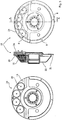
- FIG. 3 shows a knife receptacle 16 to which the knife 11 is attached.
- the blade receptacle 16 is shown in three views, wherein the middle view represents a section along the line AA, which is shown in the right-hand illustration.
- the blade holder 16 which rotates together with a drive shaft (not shown), has a base body 24, on which the contact surface 21 and the centering surface 20 are arranged for the knife.
- the knife 11 is screwed by means of the threaded holes 8 to the base body 24.
- the threaded holes 8 are arranged so that the knife can be arranged only in a single position on the blade holder.
- the blade receptacle 16 has a counterweight 15 with which the asymmetry of the blade 11 to be fastened to the blade receptacle is compensated.
- This counterweight is located below a cover 22 and within the centering surface 20.
- the counterweight 15 therefore does not have to be assembled or disassembled during assembly, disassembly or disassembly of the knife.
- recesses 19 in which additional weights can be arranged, which can be particularly helpful for a fine balancing.
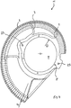
- FIG. 4 shows the knife according to the invention, in the present case, a spiral knife.
- This knife has a very large recess 7, which has a diameter D, in the present case 330 mm. At its outer radius, the knife has a cutting edge 9, which has a radius measured from the center of the recess 7 of 200 mm - 465 mm.
- the claws 3 reduce the friction between the product to be sliced and the knife.
- the knife is fastened by means of screws, which are screwed through holes 8 in the knife in the thread 8 of the blade holder on the blade holder.
- the bores are arranged along the diameter of the recess 7 so that the knife can be fixed only in a single position relative to the cutter head, so that the knife is in particular in the correct position relative to the cutter head.
- the knife can be held during its attachment to the blade holder.
- the knife has a very low weight for its size (maximum cutting radius of 500 mm), which, including the knife holder, is less than 23 kilograms. This has a positive effect on the handling of the knife, but also on the forces that occur when the knife is timing out of the cutting plane.
Abstract
Description
- Die vorliegende Erfindung betrifft ein Verfahren zum Abtrennen von Lebensmittelscheiben von mindestens einem Lebensmittelriegel mit einem rotierenden Messer, bei der der Lebensmittelriegel mit mindestens einem Transportmittel in Richtung des Messers transportierbar ist. Desweiteren betrifft die vorliegende Erfindung eine Vorrichtung zum Abtrennen von Lebensmittelscheiben von mindestens einem Lebensmittelriegel mit einem rotierenden Messer, bel der der Lebensmittelriegel mit mindestens einem Transportmittel in Richtung des Messers transportierbar ist, sowie ein Messer zum Aufschneiden von Lebensmitteln.
- Das gattungsgemäße Verfahren, die Vorrichtung sowie das Messer sind von Hochleistungsaufschneidemaschinen bekannt, wie sie beispielsweise in der
DE 100 01 338 , derEP 0 107 056 , derEP 0 867 263 sowie derGB 2 386 317 - Es war deshalb die Aufgabe der vorliegenden Erfindung ein Verfahren und eine Vorrichtung zur Verfügung zu stellen, die die Nachteile des Standes der Technik nicht aufweist.
- Gelöst wird die Aufgabe mit Verfahren zum Aufschneiden eines Lebensmittelriegels mit einer Vorrichtung, die ein rotierendes Messer und mindestens ein Transportmittel aufweist, bei dem der Lebensmittelriegel in eine Vorschubtrasse eingelegt und von dem Transportmittel in Richtung des Messers transportiert und dabei aufgeschnitten wird, wobei der Vorrichtung mindestens ein Schwingungssensor und/oder mindestens ein Produktsensor, der mindestens einen Parameter des Lebensmittelriegels ermittelt, zugeordnet wird, dessen Signal zur Überwachung und/oder Einstellung der Vorrichtung oder des Aufschneidevorgangs verwendet wird.
- Bei dem erfindungsgemäßen Verfahren werden stangenförmige oder anders geformte Lebensmittel, beispielsweise Wurst, Käse, Schinken oder dergleichen mit einer sehr hohen Schneidleistung in Scheiben geschnitten. Dabei wird beispielsweise die Lebensmittelstange mittels eines geregelten Antriebs durch eine ortsfeste Schneidebene, in der der Schnitt durch ein schnell bewegtes, in der Regel rotierendes Messer erfolgt, transportiert. Die Schelbenstärke ergibt sich aus der Vorschubstrecke des Lebensmittelriegels zwischen zwei Schnitten. Demnach erfolgt bei einer konstanten Messergeschwindigkeit die Regelung der Scheibenstärke über die Vorschubgeschwindigkeit des Lebensmittelriegels. Die geschnittenen Scheiben werden In der Regel mit konstanter Scheibenzahl zu Portionen zusammengefasst und verpackt. Für die Portionierung wird vorzugsweise das Messer aus der Schneidebene heraus bewegt und/oder das aufzuschneidende Lebensmittel zurückgezogen.
- Weiterhin erfindungsgemäß wird der Vorrichtung mindestens ein Schwingungssensor und/oder mindestens ein Produktsensor, der mindestens einen Parameter des Lebensmittelriegels ermittelt, zugeordnet, dessen Signal zur Überwachung und/oder Einstellung der Vorrichtung oder des Aufschneidevorgangs verwendet wird.
- Der Schwingungssensor wird entweder direkt an der Vorrichtung angeordnet und nimmt somit deren Schwingungen direkt auf und/oder er wird in der Nähe angeordnet und nimmt Schwingungen der Luft auf, die von der Vorrichtung angeregt wird. Bei dem Schwingungssensor kann es sich demnach beispielsweise um einen Piezosensor oder um ein Mikrophon.
- Weiterhin erfindungsgemäß wird mit einem Produktsensor mindestens ein Parameter ermittelt. Bei dem Produktsensor kann es sich um eine Kamera handeln, die Wellen des für das menschliche Auge sichtbaren Lichtes, ultraviolette Strahlung und/oder Infrarotstrahlung aufnehmen kann. Mit dieser Kamera kann zum einen festgestellt werden um was für ein Lebensmittelprodukt es sich handelt und/oder zum anderen welche Temperatur es aufweist. Bei dem Sensor kann es sich aber auch um einen einfachen Temperatursensor handeln. Weiterhin kann es sich bei dem Sensor um einen Sensor handeln, der mechanische Eigenschaften des Produktes aufnimmt. Der Sensor kann im Eingangs-, im Aufschneidebereich und stromabwärts des Messers angeordnet werden. Eine Messung stromabwärts des Messers hat den Vorteil, dass auch Werte, wie beispielsweise die Temperatur oder mechanische Werte im Kern des aufzuschneidenden Produktes ermittelt werden können.
- Das Signal des Schwingungssensors und/oder des Produktsensors wird an eine Auswerteeinheit weitergeben, das deren Signal auswertet.
- Beispielsweise kann dieses Signal zur Ermittlung des Verschleißes von Teilen, wie beispielsweise einem Lager und sonstigen bewegten Teilen herangezogen werden. Basierend auf dieser Analyse kann ein proaktives Servicekonzept erstellt werden, bei dem beispielsweise ein möglichst günstiger Wartungstermin festgelegt und/oder die benötigten Teile online bestellt werden.
- Weiterhin kann der Schwingungssensor zur Einstellung des Schneidspaltes herangezogen werden. Der Schneidspalt ist der Spalt zwischen dem Messer und einer Schneidleiste. Durch Verstellung des Messers und/oder der Schneidkante kann die Größe dieses Spaltes verändert werden. Prinzipiell sollte, für ein optimales Schneidergebnis, der Schneidspalt so klein wie möglich sein, wobei das Messer die Schneidleiste, bei dessen Rotation, nicht berühren sollte. Das Messer und/oder die Schneidleiste können nun solange aufeinander zubewegt werden, bis sie sich berühren oder fast berühren, wodurch sich die Schwingungen, die der Sensor misst verändern. Die Auswerteeinheit weiß dann, dass der Schneidspalt sehr klein oder zu gering ist. Vorzugsweise wird der Spalt dann wieder um ein vorgegebenes Maß vergrößert werden. Diese Einstellung des Schneidspalts wird vorzugsweise unter Betriebsbedingungen, bei der gewählten Schneidleistung durchgeführt. Vorzugsweise erfolgt sie nach dem das Messer zur Erzeugung eines Leerschnitts von der Schneidleiste weg- und wieder zurückbewegt worden ist. Durch die Höhe der Drehzahl des Messers, durch Temperatureinflüsse, durch die Art des aufzuschneidenden Lebensmittels und/oder durch Verschleiß verändert sich die Form des Messers und damit die Größe des Schneidspaltes während des Aufschneidens. Mit dem Signal des Schwingungssensors ist es möglich diesen Schneidspalt während des Aufschneidens eines Lebensmittels zu überprüfen und gegebenenfalls neu einzustellen und diese Einstellung beliebig oft zu wiederholen, ohne dass der Schneidvorgang unterbrochen werden muss.
- Weiterhin bevorzugt wird mit dem Schwingungssensoren der Grad der Abstumpfung des Messers ermittelt. Je nach Schärfegrad des Messers ändert sich das Schwingungsverhalten der Aufschneidevorrichtung und/oder die Geräuschentwicklung beim Schneiden der Lebensmittelprodukte. Beispielsweise durch einen Vergleich mit hinterlegten Schwingungsprofilen kann die Auswertevorrichtung ermitteln, wie scharf das Messer noch ist und welche Standzeit es noch hat, bevor es ausgewechselt werden muss und dadurch vorzugsweise eine proaktive Messerwechselstrategie erstellen. Dadurch wird die Standzeit während des Auswechselns reduziert.
- In einer weiteren bevorzugten Ausführungsform des erfindungsgemäßen Verfahrens erfolgt die Einstellung mindestens eines Maschinenparameters in Abhängigkeit von dem Signal des Produktsensors. Beispielsweise ermittelt der Produktsensor die Art des Produktes und/oder dessen Temperatur. Basierend auf diesen Messungen wird beispielsweise die Drehzahl des Messers, die Vorschubgeschwindigkeit des Lebensmittelriegels, der Schneidspalt, die Bewegung des Ablagetischs, die Axialbewegung des Messers oder des Rotors zur Erzeugung eines Leerschnitts, die Produktlage quer zur Vorschubrichtung und/oder die X-Y-Ausrichtung des Schneidkopfes eingestellt. Die Messung und die Einstellung erfolgen vorzugsweise automatisch, so dass Bedienfehler zumindest reduziert werden. Beispielsweise kann bei gefrorenen Produkten die Drehzahl des Messers reduziert werden, um zu verhindern, dass die abgeschnittenen Produkte eine unerwünschte Flugbahn haben.
- Die abgeschnittenen Lebensmittelscheiben fallen in der Regel auf einen Ablagetisch, auf dem entsprechende Portionen gebildet werden. Durch bestimmte Bewegungen dieses Ablagetisches können unterschiedlich ausgebildete Portionen, beispielsweise geschindelte Portionen erzeugt werden. Die Bewegung dieses Tisches kann nun abhängig von dem Signal eines Sensors gesteuert werden, da sich der Ablageort in Abhängigkeit von beispielsweise Produktparametern wie Temperatur ändert.
- Vorzugsweise werden mehrere Lebensmittelriegel gleichzeitig aufgeschnitten.
- Gelöst wird die oben gestellte Aufgabe außerdem durch eine Vorrichtung zum Abtrennen von Lebensmittelscheiben von mindestens einem Lebensmittelriegel mit einem rotierenden Messer, bei der der Lebensmittelriegel mit mindestens einem Transportmittel in Richtung des Messers transportierbar ist, dadurch gekennzeichnet, dass ihr mindestens ein Schwingungs- und/oder mindestens einen Produktsensor, zugeordnet ist.
- Die zu dem erfindungsgemäßen Verfahren gemachte Offenbarung gilt für die erfindungsgemäße Vorrichtung gleichermaßen.
- Eine weitere Aufgabe der Vorrichtung war es eine möglichst hygienischen, leicht zu betreibende Vorrichtung zum Abtrennen von Lebensmittelscheiben von mindestens einem Lebensmittelriegel zur Verfügung zu stellen.
- Gelöst wird diese Aufgabe mit einer Vorrichtung zum Abtrennen von Lebensmittelscheiben von mindestens einem Lebensmittelriegel mit einem rotierenden, nicht rotationsymmetrischen Messer, bei der der Lebensmittelriegel mit mindestens einem Transportmittel in Richtung des Messers transportierbar ist und die Asymmetrie des Messers durch ein Gegengewicht ausgeglichen wird und das Gegengewicht, in der das Messer antreibenden Welle und/oder in der Messeraufnahme angeordnet ist.
- Für den rotierenden Betrieb eines nicht rotationssymmetrischen Messers wird ein Gegengewicht benötigt. Erfindungsgemäß ist dieses Gegengewicht nun nicht, wie beim Stand der Technik an dem Messer selbst sondern in der das Messer antreibenden Welle und/oder in der Messeraufnahme angeordnet, wobei die Messeraufnahme der bevorzugte Ort für die Anordnung des Gegengewichtes ist. Eine Messeraufnahme ist das Teil der Aufschneidemaschine, an dem das Messer gelagert ist und die sich dreht. Die Messeraufnahme kann ein Tell der Welle sein, vorzugsweise ein Teil, dass teleskopierbar ist, d.h. das relativ zum Rest der Welle verschiebbar ist. Die Messeraufnahme kann aber auch direkt angetrieben werden und ist damit auch die Welle.
- Die erfindungsgemäße Vorrichtung ist sehr hygienisch, weil das Gegengewicht nicht mehr verschmutzen kann. Bei einem Messerwechsel muss das Gegengewicht nicht demontiert werden.
- Eine weitere Aufgabe der vorliegenden Erfindung war es die Bedienbarkeit einer Aufschneidemaschine zu vereinfachen und die Zeit einen Messerwechsel zu reduzieren.
- Gelöst wird die Aufgabe mit einem Verfahren zum Wechseln von einem rotierend angeordneten, nicht rotationssymmetrischen Messers einer Vorrichtung zum Aufschneiden von Lebensmittelriegeln, die ein Gegengewicht für das Messer aufweist, wobei beim Messerwechsel nur das Messer und nicht das Gegengewicht demontiert wird.
- Bei dem erfindungsgemäßen muss in regelmäßigen Abständen ein rotierend angeordnetes Messer, das jedoch nicht rotationssymmetrisch ist ausgewechselt werden. Bei einem derartigen Messer wird für einen ordnungsgemäßen Betrieb der Aufschneidevorrichtung ein Gegengewicht benötigt, um bei der Drehung des Messers tolerierbare Schwingungen zu erhalten. Erfindungsgemäß wird dieses Gegengewicht bei einem Messerwechsel nicht demontiert sondern lediglich das Messer selbst, wodurch der Vorgang des Messerwechsels vereinfacht wird.
- Noch eine Aufgabe der vorliegenden Erfindung bestand darin ein Messer zum Aufschneiden von Lebensmittelriegeln zur Verfügung zu stellen, das für eine Verschiebung des Messers zur Erzeugung eines Leerschnitts möglichst geeignet ist. Gelöst wird die Aufgabe mit einem Messer zum Aufschneiden von Lebensmitteln mit einer Schneide und einer Ausnehmung, bei der mindestens eine Dimension der Ausnehmung mindestens 140 mm und maximal 450 beträgt.
- Erfindungsgemäß weist das Messer eine Ausnehmung auf, bei der mindestens eine Dimension mindestens 140 mm und maximal 450 beträgt. Vorzugsweise handelt es sich bei der Ausnehmung um einen Kreis, dessen Durchmesser zwischen 140 und 450 mm beträgt. Vorzugsweise beträgt die Abmessung der Dimension, vorzugsweise der Durchmesser der Ausnehmung, mindestens 200 und maximal 435 mm, besonders bevorzugt 240- 360 mm. Diese Ausnehmung dient vorzugsweise zur Lagerung und/oder Zentrierung des Messers an der Vorrichtung.
- Vorzugsweise beträgt der Radius der Schneide zwischen 250 und 550 mm. Besonders bevorzugt handelt es sich bei dem Messer um ein Spiralmesser, so dass sich der Radius mit der Lauflänge der Schneide ändert. Der Radius wird vorzugsweise von der Mitte der Ausnehmung ausgemessen.
- Das Messer wird mit Verbindungsmittein mit der Aufschneidevorrichtung verbunden. Vorzugsweise befinden sich diese Mittel außerhalb der Ausnehmung.
- Vorzugsweise beträgt das Gewicht des Messers inklusive einer Halterung, mit der das Messer zur Versbindung mit der Vorrichtung aufgehängt werden kann, maximal 23 kg.
- Vorzugsweise beträgt das Verhältnis von dem Radius der Schneide zu der größten Dimension der Ausnehmung an jeder Stelle < 2,0, bevorzugt < 1,7, besonders bevorzugt < 1,5 und am meisten bevorzugt < 1,3. Vorzugsweise ist dieser Wert immer > 0,5, besonders bevorzugt > 0,55 und ganz besonders bevorzugt > 0,58.
- Im Folgenden wird die Erfindung anhang der Figuren erläutert. Diese Erläuterungen sind lediglich beispielhaft und schränken den allgemeinen Erfindungsgedanken nicht ein. Die Erläuterungen gelten für alle Erfindungsgegenstände gleichermaßen.
- Figuren 1, 2
- zeigen die erfindungsgemäße Aufschneidevorrichtung.
- Figur 3
- zeigt die Messeraufnahme mit dem Gegengewicht
- Figur 4
- zeigt das erfindungsgemäße Messer.
- Die erfindungsgemäße Vorrichtung 5 weist mindestens einen Schwingungssensor (nicht dargestellt) und/oder mindestens ein Produktsensor 13, der mindestens einen Parameter des Lebensmittelriegels ermittelt, auf. Das Signal mindestens einer dieser Sensoren wird zur Überwachung und/oder Einstellung der Vorrichtung oder des Aufschneidevorgangs verwendet.
- Der Schwingungssensor wird entweder direkt an der Vorrichtung angeordnet und nimmt somit deren Schwingungen direkt auf und/oder er wird in der Nähe angeordnet und nimmt Schwingungen der Luft auf, die von der Vorrichtung angeregt wird. Bei dem Schwingungssensor kann es sich demnach beispielsweise um einen Piezosensor oder um ein Mikrophon.
- Der Schwingungssensor misst die Frequenz und die Amplitude der auftretenden Schwingungen.
- Mit dem Produktsensor 13 wird mindestens ein Parameter ermittelt. In dem vorliegenden Fall handelt es sich um eine Kamera, die Wellen des für das menschliche Auge sichtbaren Lichtes, ultraviolette Strahlung und/oder Infrarotstrahlung aufnehmen und verarbeiten kann. Der Fachmann versteht, dass es bei bestimmten Anwendungen jedoch auch sinnvoll sein kann, die Wellenlänge des beobachteten Lichtes zu filtern. Mit dieser Kamera kann zum einen festgestellt werden, um was für ein Lebensmittelprodukt es sich handelt und/oder zum anderen welche Temperatur es aufweist. Bei dem Sensor kann es sich auch um einen Sensor handeln, der mechanische Eigenschaften des Produktes aufnimmt. Der Sensor kann im Eingangs-, im Aufschneidebereich und stromabwärts des Messers angeordnet werden. Bei der Darstellung gemäß
Figur 2 ist die Kamera 13 Messung des Messers angeordnet und kann beispielsweise die Temperatur im Kern des Lebensmittelriegels ermitteln. Die Kamera kann auf den Lebensmittelriegel 2 und/oder auf die abgeschnittenen Lebensmittelscheiben 12 gerichtet sein. - Das Signal des Schwingungssensors und/oder des Produktsensors wird an eine Auswerteeinheit weitergeben, das deren Signal auswertet. Eine Auswertung kann beispielsweise durch einen Vergleich der gemessenen Frequenzen und Amplituden der Schwingungen mit hinterlegten Werten erfolgen, um Veränderungen festzustellen. Dadurch lässt sich Verschleißes von Teilen, wie beispielsweise einem Lager und sonstigen bewegten Teilen ermitteln.
- Weiterhin kann der Schwingungssensor zur Einstellung des Schneidspaltes herangezogen werden. Der Schneidspalt ist der Spalt zwischen dem Messer 11 und einer Schneidleiste 1. Durch Verstellung des Messers 11 und/oder der Schneidkante 1 kann die Größe dieses Spaltes verändert werden. Prinzipiell sollte, für ein optimales Schneidergebnis, der Schneidspalt so klein wie möglich sein, wobei das Messer die Schneidleiste, bei dessen Rotation, nicht berühren sollte. Das Messer und/oder die Schneidleiste können nun, bei sich drehendem Messer 11, solange aufeinander zubewegt werden, bis sie sich berühren oder fast berühren, wodurch sich die Schwingungen, die der Sensor misst, verändern. Insbesondere bei einer Berührung von Messer 11 und Schneidleiste 1 wird es zu einer Geräuschentwicklung kommen, die der Schwingungssensor misst. Die Auswerteeinheit weiß dann, dass der Schneidspalt sehr klein oder zu gering ist. Vorzugsweise wird der Spalt dann wieder um ein vorgegebenes Maß vergrößert, indem die Schneidleiste und oder das Messer voneinander weg bewegt werden. Diese Einstellung des Schneidspalts wird vorzugsweise unter Betriebsbedingungen, bei der gewählten Schneidleistung (Nenndrehzahl) durchgeführt. Vorzugsweise erfolgt sie nachdem das Messer zur Erzeugung eines Leerschnitts von der Schneidleiste 1 weg- und wieder zurückbewegt worden ist. Durch die Höhe der Drehzahl des Messers, durch Temperatureinflüsse, durch die Art des aufzuschneidenden Lebensmittels und/oder durch Verschleiß verändert sich die Form des Messers und damit die Größe des Schneidspaltes während des Aufschneidens. Mit dem Signal des Schwingungssensors ist es möglich diesen Schneidspalt während des Aufschneidens eines Lebensmittels zu überprüfen und gegebenenfalls neu einzustellen und diese Einstellung beliebig oft zu wiederholen, ohne dass der Schneidvorgang unterbrochen oder die Drehzahl des Messers reduziert werden muss.
- Weiterhin bevorzugt wird mit den Schwingungssensoren der Grad der Abstumpfung des Messers ermittelt. Je nach Schärfegrad des Messers ändert sich das Schwingungsverhalten der Aufschneidevorrichtung und/oder die Geräuschentwicklung beim Schneiden der Lebensmittelprodukte. Beispielsweise durch einen Vergleich mit hinterlegten Schwingungsprofilen kann die Auswertevorrichtung ermitteln, wie scharf das Messer noch ist und welche Standzeit es noch hat, bevor es ausgewechselt werden muss und dadurch vorzugsweise eine proaktive Messerwechselstrategie erstellen. Dadurch wird die Stillstandszeit während des Auswechselns reduziert.
- Weiterhin erfolgt die Einstellung mindestens eines Maschinenparameters in Abhängigkeit von dem Signal des Produktsensors 13 Beispielsweise ermittelt der Produktsensor die Art des Produktes und/oder dessen Temperatur. Basierend auf dieser Messung wird beispielsweise die Drehzahl des Messers 11, die Vorschubgeschwindigkeit des Lebensmittelriegels 2, der Schneidspalt, die Bewegung des Ablagetischs und/oder die X-Y-Ausrichtung des Schneidkopfes 10 eingestellt. Die Messung und die Einstellung erfolgen vorzugsweise automatisch, so dass Bedienfehler zumindest reduziert werden. Beispielsweise kann bei gefrorenen Produkten die Drehzahl des Messers reduziert werden, um zu verhindern, dass die abgeschnittenen Produkte eine unerwünschte Flugbahn haben.
-
Figur 3 zeigt eine Messeraufnahme 16, an der das Messer 11 befestigt wird. Die Messeraufnahme 16 ist in drei Ansichten dargestellt, wobei die mittlere Ansicht ein Schnitt entlang der Linie A-A darstellt, die in der rechten Darstellung eingezeichnet ist. Die Messeraufnahme 16, die sich zusammen mit einer Antriebswelle (nicht dargestellt) dreht, weist ein Grundkörper 24 auf, an dem die Anlagefläche 21 sowie die Zentrierfläche 20 für das Messer angeordnet sind. Das Messer 11 wird mit Hilfe der Gewindebohrungen 8 an den Grundkörper 24 angeschraubt. Die Gewindebohrungen 8 sind so angeordnet, dass das Messer nur in einer einzigen Lage an der Messeraufnahme angeordnet werden kann. Desweiteren weist die Messeraufnahme 16 ein Gegengewicht 15 auf, mit der die Asymmetrie des an der Messeraufnahme zu befestigenden Messers 11 ausgeglichen wird. Dieses Gegengewicht befindet sich unterhalb einer Abdeckung 22 und innerhalb der Zentrierfläche 20. Bei der Montage des Messers 11 an der Messeraufnahme 16 wird das Messer über das Ausgleichsgewicht 15 bewegt und an der Anlagefläche 21 bzw. der Zentrierfläche 20 angelegt. Das Gegengewicht 15 muss deshalb bei einer Montage, Demontage bzw. Demontage des Messers nicht montiert oder demontiert werden. In dem Gegengewicht 15 befinden sich Ausnehmungen 19, in denen zusätzliche Gewichte angeordnet werden können, was insbesondere für eine Feinauswuchtung hilfreich sein kann. -
Figur 4 zeigt das erfindungsgemäße Messer, in dem vorliegenden Fall ein Spiralmesser. Dieses Messer weist eine sehr große Ausnehmung 7 auf, die einen Durchmesser D, in dem vorliegenden Fall 330 mm, hat. An ihrem Außenradius weist das Messer eine Schneide 9 auf, die einen Radius gemessen ab dem Mittelpunkt der Ausnehmung 7 von 200 mm - 465 mm aufweist. Die Freinehmungen 3 reduzieren die Reibung zwischen dem aufzuschneidenden Produkt und dem Messer. Das Messer wird mittels Schrauben, die durch Bohrungen 8 in dem Messer in die Gewinde 8 der Messeraufnahme geschraubt werden, an der Messeraufnahme befestigt. Die Bohrungen sind so entlang des Durchmessers der Ausnehmung 7 angeordnet, dass das Messer nur in einer einzigen Lage relativ zu dem Messerkopf befestigt werden kann, so dass sich das Messer insbesondere in der richtigen Lage relativ zu dem Messerkopf befindet. Mittels der Ausnehmungen 23 kann das Messer während seiner Befestigung an der Messeraufnahme gehalten werden. Das Messer weist für seine Größe (Schneidradius maximal 500 mm) ein sehr geringes Gewicht auf, das inklusive der Messerhalterung weniger als 23 Kilogramm beträgt. Dies wirkt sich positiv beim Handling des Messers aus, aber auch bei den Kräften, die bei einer Taktung des Messers aus der Schneidebene heraus auftreten. -
- 1
- Schneidkante, Schneidleiste
- 2
- Lebensmittelriegel
- 3
- Freinehmung
- 4
- Transportmittel, Traktionsband
- 5
- Aufschneidevorrichtung
- 6
- Schneidebene
- 7
- Ausnehmung
- 8
- Befestigungsmittel
- 9
- Schneide
- 10
- Schneidkopf
- 11
- Messer
- 12
- Lebensmittelscheibe
- 13
- Produktsensor
- 14
- Produkttrasse
- 15
- Gegengewicht
- 16
- Messeraufnahme
- 17
- dem Messer abgewandtes Ende des Produktriegels
- 18
- Greifer
- 19
- Auswuchtgewicht
- 20
- Zentrierfläche
- 21
- Anlagefläche
- 22
- Abdeckung
- 23
- Ausnehmung
- 24
- Grundkörper
- D
- Dimension, Länge, Durchmesser der Ausnehmung 7
- R
- Radius der Schneide
Claims (9)
- Verfahren zum Aufschneiden eines Lebensmittelriegels (2) mit einer Vorrichtung, die ein rotierendes Messer (11) und mindestens eine Transportmittel (4, 18) aufweist, bei dem der Lebensmittelriegel in eine Vorschubtrasse (14) eingelegt und von dem Transportmittel (4, 18) in Richtung des Messers (11) transportiert und dabei aufgeschnitten wird, dadurch gekennzeichnet, dass der Vorrichtung mindestens ein Produktsensor, der mindestens einen Parameter des Lebensmittelriegels ermittelt, zugeordnet wird, dessen Signal zur Überwachung und/oder Einstellung der Vorrichtung oder des Aufschneidevorgangs verwendet wird.
- Verfahren nach einem der voranstehenden Ansprüche, dadurch gekennzeichnet, dass die Vorrichtung eine Schneidleiste (1) aufweist und der Schneidspalt zwischen dem Messer (11) und der Schneidleiste (1) unter Zuhilfenahme des Produktsensors durchgeführt wird.
- Verfahren nach Anspruch 3, dadurch gekennzeichnet, dass der Schneidspalt bei der jeweiligen Schneiddrehzahl durchgeführt wird.
- Verfahren nach einem der voranstehenden Ansprüche, dadurch gekennzeichnet, dass zur Portionsbildung mindestens ein Leerschnitt ausgeführt wird und dass die Einstellung des Schneidspalts nach einem Leerschnitt erfolgt.
- Verfahren nach einem der voranstehenden Ansprüche, dadurch gekennzeichnet, dass mit dem Produktsensor die Abstumpfung des Messers (11) ermittelt wird.
- Verfahren nach einem der voranstehenden Ansprüche, dadurch gekennzeichnet, dass die Einstellung mindestens eines Maschinenparameters in Abhängigkeit von dem Signal des Produktsensors erfolgt.
- Verfahren nach Anspruch 6, dadurch gekennzeichnet, dass die Drehzahl des Messers, die Vorschubgeschwindigkeit des Lebensmittelriegels, der Schneidspalt, die Bewegung des Ablagetischs die Axialbewegung des Messers oder des Rotors zur Erzeugung eines Leerschnitts, die Produktlage quer zur Vorschubrichtung und/oder die X-Y-Ausrichtung des Schneidkopfes geregelt wird.
- Verfahren nach einem der voranstehenden Ansprüche, dadurch gekennzeichnet, dass mehrere Lebensmittelriegel gleichzeitig aufgeschnitten werden.
- Vorrichtung zum Abtrennen von Lebensmittelscheiben (12) von mindestens einem Lebensmittelriegel (2) mit einem rotierenden Messer, bei der der Lebensmittelriegel (2) mit mindestens einem Transportmittel (4) in Richtung des Messers (11) transportierbar ist, dadurch gekennzeichnet, dass ihr mindestens einen Produktsensor, zur Bestimmung mindestens eines Parameters des Lebensmittelriegels zugeordnet ist.
Priority Applications (3)
| Application Number | Priority Date | Filing Date | Title |
|---|---|---|---|
| DK12174769.5T DK2508310T3 (en) | 2008-04-18 | 2009-04-17 | Process for cutting food |
| EP12174769.5A EP2508310B1 (de) | 2008-04-18 | 2009-04-17 | Verfahren zum Aufschneiden von Lebensmitteln |
| PL12001764T PL2471635T3 (pl) | 2008-04-18 | 2009-04-17 | Sposób nacinania artykułów spożywczych |
Applications Claiming Priority (2)
| Application Number | Priority Date | Filing Date | Title |
|---|---|---|---|
| DE200810019776 DE102008019776A1 (de) | 2008-04-18 | 2008-04-18 | Verfahren, Vorrichtung sowie Messer zum Aufschneiden von Lebensmitteln |
| EP09753594.2A EP2279064B2 (de) | 2008-04-18 | 2009-04-17 | Verfahren zum aufschneiden von lebensmitteln |
Related Parent Applications (3)
| Application Number | Title | Priority Date | Filing Date |
|---|---|---|---|
| EP09753594.2A Division EP2279064B2 (de) | 2008-04-18 | 2009-04-17 | Verfahren zum aufschneiden von lebensmitteln |
| EP09753594.2A Division-Into EP2279064B2 (de) | 2008-04-18 | 2009-04-17 | Verfahren zum aufschneiden von lebensmitteln |
| EP09753594.2 Division | 2009-04-17 |
Related Child Applications (2)
| Application Number | Title | Priority Date | Filing Date |
|---|---|---|---|
| EP12174769.5A Division-Into EP2508310B1 (de) | 2008-04-18 | 2009-04-17 | Verfahren zum Aufschneiden von Lebensmitteln |
| EP12174769.5A Division EP2508310B1 (de) | 2008-04-18 | 2009-04-17 | Verfahren zum Aufschneiden von Lebensmitteln |
Publications (2)
| Publication Number | Publication Date |
|---|---|
| EP2471635A1 true EP2471635A1 (de) | 2012-07-04 |
| EP2471635B1 EP2471635B1 (de) | 2015-11-04 |
Family
ID=40887075
Family Applications (4)
| Application Number | Title | Priority Date | Filing Date |
|---|---|---|---|
| EP20110008345 Active EP2425940B1 (de) | 2008-04-18 | 2009-04-17 | Messer zum Aufschneiden von Lebensmitteln |
| EP12001764.5A Active EP2471635B1 (de) | 2008-04-18 | 2009-04-17 | Verfahren zum Aufschneiden von Lebensmitteln |
| EP09753594.2A Active EP2279064B2 (de) | 2008-04-18 | 2009-04-17 | Verfahren zum aufschneiden von lebensmitteln |
| EP12174769.5A Active EP2508310B1 (de) | 2008-04-18 | 2009-04-17 | Verfahren zum Aufschneiden von Lebensmitteln |
Family Applications Before (1)
| Application Number | Title | Priority Date | Filing Date |
|---|---|---|---|
| EP20110008345 Active EP2425940B1 (de) | 2008-04-18 | 2009-04-17 | Messer zum Aufschneiden von Lebensmitteln |
Family Applications After (2)
| Application Number | Title | Priority Date | Filing Date |
|---|---|---|---|
| EP09753594.2A Active EP2279064B2 (de) | 2008-04-18 | 2009-04-17 | Verfahren zum aufschneiden von lebensmitteln |
| EP12174769.5A Active EP2508310B1 (de) | 2008-04-18 | 2009-04-17 | Verfahren zum Aufschneiden von Lebensmitteln |
Country Status (10)
| Country | Link |
|---|---|
| US (2) | US20110296964A1 (de) |
| EP (4) | EP2425940B1 (de) |
| AT (1) | ATE552948T1 (de) |
| DE (1) | DE102008019776A1 (de) |
| DK (2) | DK2471635T3 (de) |
| ES (4) | ES2561880T3 (de) |
| HU (2) | HUE033040T2 (de) |
| PL (4) | PL2508310T3 (de) |
| PT (1) | PT2508310T (de) |
| WO (1) | WO2009143939A2 (de) |
Cited By (1)
| Publication number | Priority date | Publication date | Assignee | Title |
|---|---|---|---|---|
| DE102022113920A1 (de) | 2022-06-02 | 2023-12-07 | Multivac Sepp Haggenmüller Se & Co. Kg | Messer, Schneideinheit sowie Aufschneide-Maschine |
Families Citing this family (37)
| Publication number | Priority date | Publication date | Assignee | Title |
|---|---|---|---|---|
| DE102009011860A1 (de) † | 2009-03-05 | 2010-09-09 | Weber Maschinenbau Gmbh Breidenbach | Vorrichtung und Verfahren zur Einstellung eines Schneidspalts an einer Schneidvorrichtung |
| DE102009059856A1 (de) * | 2009-12-21 | 2011-06-22 | Weber Maschinenbau GmbH Breidenbach, 35236 | Vorrichtung zum Aufschneiden von Lebensmittelprodukten |
| US20110185865A1 (en) * | 2009-12-21 | 2011-08-04 | Weber Maschinenbau Gmbh Breidenbach | Apparatus for slicing food products |
| DE102010012709A1 (de) * | 2010-03-25 | 2011-09-29 | Weber Maschinenbau Gmbh Breidenbach | Vorrichtung und Verfahren zum Aufschneiden von Lebensmittelprodukten |
| DE102010019248A1 (de) * | 2010-05-03 | 2011-11-03 | CFS Bühl GmbH | Verfahren zum Betrieb einer Aufschneidevorrichtung mit mehrspurigen Antrieben |
| DE102010034360A1 (de) * | 2010-06-11 | 2011-12-15 | CFS Bühl GmbH | Verfahren und Vorrichtung zur Schneidspalteinstellung einer Aufschneidevorrichtung |
| CN103038625B (zh) * | 2010-07-20 | 2014-12-10 | 日清制粉集团本社股份有限公司 | 脆度测定装置及脆度测定法 |
| DE102010045823A1 (de) * | 2010-09-20 | 2012-03-22 | Rudi Siller | Scheibenschneidmaschine für strangförmige Lebensmittel |
| DE102011109067A1 (de) * | 2011-08-01 | 2013-02-07 | Weber Maschinenbau Gmbh Breidenbach | Vorrichtung und Verfahren zum Aufschneiden von Lebensmittelprodukten |
| DE102011114180A1 (de) * | 2011-09-22 | 2013-03-28 | Weber Maschinenbau Gmbh Breidenbach | Vorrichtung zum Aufschneiden von einem Lebensmittelprodukt und Vorrichtung mit einem Roboter |
| DE102011119719A1 (de) * | 2011-11-30 | 2013-06-06 | GEA CFS Bühl GmbH | Verfahren zum Aufschneiden eines Lebensmittelriegels unter Verwendung eines Schwingungssensors |
| DE102012007013A1 (de) | 2012-04-05 | 2013-10-10 | Weber Maschinenbau Gmbh Breidenbach | Schnittstelle zwischen Messer und Messeraufnahme |
| JP5656915B2 (ja) * | 2012-05-21 | 2015-01-21 | ユニ・チャーム株式会社 | トウを含む複数の繊維を有するウエブ部材の切断装置、及び切断方法 |
| JP5836194B2 (ja) * | 2012-05-21 | 2015-12-24 | ユニ・チャーム株式会社 | トウを含む複数の繊維を有する連続ウエブの切断装置、及び切断方法 |
| DE102012214741A1 (de) | 2012-08-20 | 2014-02-20 | Textor Maschinenbau GmbH | Vorrichtung und Verfahren zum Aufschneiden von Lebensmittelprodukten |
| DE102012218853A1 (de) | 2012-10-16 | 2014-04-17 | Textor Maschinenbau GmbH | Aufschneidevorrichtung |
| DE102012024947A1 (de) * | 2012-12-19 | 2014-06-26 | Weber Maschinenbau Gmbh Breidenbach | Verfahren und Lebensmittelaufschneidevorrichtung mit Schneidkraftbestimmung |
| DE102012224195A1 (de) | 2012-12-21 | 2014-06-26 | Textor Maschinenbau GmbH | Verfahren und Vorrichtung zum Einstellen eines Schneidspalts |
| WO2014128145A1 (en) * | 2013-02-19 | 2014-08-28 | Gea Food Solutions Germany Gmbh | Slicer with a vibrating knife |
| DE102013214663A1 (de) * | 2013-07-26 | 2015-01-29 | Weber Maschinenbau Gmbh Breidenbach | Vorrichtung zum Aufschneiden von Lebensmittelprodukten |
| DE102013218158A1 (de) * | 2013-09-11 | 2015-03-12 | Weber Maschinenbau Gmbh Breidenbach | Verfahren zum Ermitteln einer axialen Referenzstellung eines Schneidmessers |
| US20160250767A1 (en) * | 2013-10-30 | 2016-09-01 | Gea Food Solutions Germany Gmbh | Slicer blade made of plastics |
| CA2944668A1 (en) * | 2014-04-09 | 2015-10-15 | Gea Food Solutions Germany Gmbh | Slicing device comprising rapid-manufacturing components |
| CH710403B1 (de) * | 2014-11-24 | 2019-06-14 | Multivac Haggenmueller Kg | Aufschnittschneidmaschine. |
| US20170368707A1 (en) * | 2014-11-25 | 2017-12-28 | GEA Food Solution Germany GmbH | Integrally bonded gripper |
| DE102015003632A1 (de) | 2015-03-19 | 2016-09-22 | Weber Maschinenbau Gmbh Breidenbach | Lebensmittelaufschneidevorrichtung mit Vorkühlungseinrichtung |
| WO2016202508A1 (de) * | 2015-06-15 | 2016-12-22 | Gea Food Solutions Germany Gmbh | Verfahren zum aufschneiden eines lebensmittelriegels unter verwendung eines temperatursensors |
| DE102016101753A1 (de) * | 2016-02-01 | 2017-08-03 | Textor Maschinenbau GmbH | Aufschneiden von lebensmittelprodukten |
| US10836065B2 (en) | 2017-01-04 | 2020-11-17 | Provisur Technologies, Inc. | Exposed load cell in a food processing machine |
| US10639798B2 (en) | 2017-01-04 | 2020-05-05 | Provisur Technologies, Inc. | Gripper actuating system in a food processing machine |
| US10160602B2 (en) | 2017-01-04 | 2018-12-25 | Provisur Technologies, Inc. | Configurable in-feed for a food processing machine |
| US9950869B1 (en) | 2017-01-04 | 2018-04-24 | Provisur Technologies, Inc. | Belt tensioner in a food processing machine |
| DK3495104T3 (da) * | 2017-12-05 | 2020-09-28 | Marel Meat Bv | Et fødevareseparatorapparat |
| CN108406887A (zh) * | 2018-03-22 | 2018-08-17 | 山东农业大学 | 一种基于图像视觉技术的条状果蔬加工装置及加工方法 |
| DE112019001833A5 (de) | 2018-05-08 | 2020-12-24 | Gea Food Solutions Germany Gmbh | Asymmetrische montage- und stabilitätsoptimierte Vorrichtung zum Aufschneiden von Lebensmittelriegeln |
| US11647699B2 (en) * | 2019-10-15 | 2023-05-16 | Dinotooth Cutter, LLC | Tree saw |
| WO2023135306A1 (de) * | 2022-01-17 | 2023-07-20 | Gea Food Solutions Germany Gmbh | Vorrichtung zum schneiden von lebensmitteln in scheiben |
Citations (7)
| Publication number | Priority date | Publication date | Assignee | Title |
|---|---|---|---|---|
| EP0107056A2 (de) | 1982-10-22 | 1984-05-02 | Natec Reich, Summer GmbH & Co. KG | Maschine zum Schneiden von Schneidgutriegeln |
| EP0867263A2 (de) | 1997-03-27 | 1998-09-30 | BIFORCE Anstalt | Produktzuführungssystem für eine Aufschnittschneidemaschine |
| DE10001338A1 (de) | 2000-01-17 | 2001-08-02 | Schindler & Wagner Gmbh & Co | Schneidmaschine für laibförmige Produkte |
| GB2377362A (en) * | 2001-07-13 | 2003-01-15 | Aew Eng Co Ltd | Non-stop slicing machine controlled by upstream sensor |
| GB2386317A (en) | 2002-03-13 | 2003-09-17 | Aew Eng Co Ltd | Slicer with a claw which passes through a gap in a conveyor |
| DE10333661A1 (de) * | 2003-07-23 | 2005-02-10 | Cfs Kempten Gmbh | Axial verschiebbares Messer |
| DE102004006120A1 (de) * | 2004-02-06 | 2005-08-25 | Cfs Kempten Gmbh | Aufschneidevorrichtung mit verschiebbaren Mundstücken |
Family Cites Families (79)
| Publication number | Priority date | Publication date | Assignee | Title |
|---|---|---|---|---|
| GB307126A (en) | 1927-03-07 | 1929-03-14 | Fiennes Thomas Lambert | Improvements in or relating to bacon slicing machines and the like |
| GB324252A (en) | 1929-02-07 | 1930-01-23 | Berkel & Parnall Mach Mfg Co | Improvements relating to slicing machines |
| US1957623A (en) * | 1931-11-21 | 1934-05-08 | Ind Patents Corp | Slicing machine |
| US1973526A (en) * | 1932-03-23 | 1934-09-11 | Ward Baking Co | Slicing apparatus and method |
| GB496562A (en) | 1937-05-31 | 1938-11-30 | Berkel & Parnall Mach Mfg Co | Improvements in last-slice holders of slicing-machines |
| US2472876A (en) * | 1944-04-21 | 1949-06-14 | Us Slicing Machine Co | Rotary disk knife |
| DE1035521B (de) | 1957-11-12 | 1958-07-31 | Faber Castell A W | Radiergummi |
| US3299925A (en) * | 1964-07-16 | 1967-01-24 | Swift & Co | Blade design |
| US3491818A (en) | 1967-04-27 | 1970-01-27 | Hobam Inc | Knife assembly for meat cutting machine |
| AT326514B (de) | 1972-08-22 | 1975-12-10 | Kuchler Fritz | Ablegeeinrichtung für eine aufschneidemaschine |
| CH565592A5 (de) * | 1972-08-31 | 1975-08-29 | Tecmed Ag | |
| DE2306822A1 (de) | 1973-02-12 | 1974-08-15 | Paul Dipl Ing Kohlhaas | Scheibenmesser, insbesondere umlaufendes scheibenmesser |
| US3921485A (en) * | 1974-06-25 | 1975-11-25 | Itt | Rotary blade assembly |
| US3969966A (en) * | 1975-06-09 | 1976-07-20 | Cashin Systems Corporation | Apparatus for slicing meat products |
| US4015494A (en) | 1975-06-24 | 1977-04-05 | Cashin Systems Corporation | Cold cut slicing system |
| US4043238A (en) * | 1976-04-21 | 1977-08-23 | Sanders Associates, Inc. | Cable cutter |
| US4379416A (en) * | 1977-06-01 | 1983-04-12 | Brain Dust Patents Establishment | Food-slicing machine and method |
| DE8007660U1 (de) | 1980-03-20 | 1984-01-26 | Dipl.-Ing. Schindler & Wagner KG, 7067 Plüderhausen | Schneidmaschine |
| DE3412743C1 (de) | 1984-04-05 | 1985-10-10 | Alexanderwerk Ag, 5630 Remscheid | Messerkopf fuer Kutter |
| US4625782A (en) * | 1985-08-05 | 1986-12-02 | Jameson Gary O | Log splitter |
| DE3617349A1 (de) | 1986-05-23 | 1987-11-26 | Knecht Gmbh Maschbau | Messerkopf fuer fleischkutter |
| DE3935320C2 (de) | 1988-12-07 | 1996-04-25 | Walter Feuring | Messerkopf für Kuttermesser |
| DE58904226D1 (de) * | 1989-08-24 | 1993-06-03 | Schenck Ag Carl | Verfahren zur schadensfrueherkennung an maschinenteilen. |
| US5058434A (en) * | 1990-02-27 | 1991-10-22 | Carl Schenck Ag | Process for early detection of damage to machine parts |
| US5065656A (en) * | 1990-09-21 | 1991-11-19 | Oscar Mayer Foods Corporation | Food slicing with multiple cutting surface blade |
| DE4031671C2 (de) * | 1990-10-05 | 1994-02-24 | Natec Reich Summer Gmbh Co Kg | Kreismesser zum Schneiden von Lebensmitteln, insbesondere Wurst und Käse |
| DE9107225U1 (de) | 1991-06-12 | 1991-09-19 | Holac Maschinenbau Gmbh, 7920 Heidenheim, De | |
| DE4214264C2 (de) | 1992-05-01 | 1994-06-01 | Natec Reich Summer Gmbh Co Kg | Schneidevorrichtung zum aufschneiden von lebensmittelprodukten, insbesondere wurst, schinken, speck, fleisch, kaese und dergleichen |
| US5988033A (en) * | 1992-10-29 | 1999-11-23 | Kraft Foods, Inc. | Food slicing apparatus, blade and method |
| DE4413568C5 (de) | 1994-04-19 | 2007-11-15 | Weber Maschinenbau Gmbh & Co. Kg | Verfahren und Vorrichtung zum Aufschneiden von Lebensmittelprodukten |
| DE4429046A1 (de) | 1994-08-16 | 1996-02-22 | Biforce Anstalt | Slicermesser |
| US5628237A (en) * | 1994-10-11 | 1997-05-13 | Formax, Inc. | Slicing machine for two or more food loaves |
| JPH08257982A (ja) | 1995-03-22 | 1996-10-08 | Ryowa Kk | 食品スライス機 |
| DE19518597C2 (de) * | 1995-05-20 | 1999-02-25 | Schindler & Wagner Kg | Schneidmaschine |
| DE19525742A1 (de) | 1995-07-14 | 1997-01-16 | Biforce Anstalt | Produktzuführung für eine Schneidvorrichtung |
| DE19612055A1 (de) * | 1996-03-27 | 1997-10-02 | Wabaema Gmbh | Sichelmesser |
| DE19654733C1 (de) * | 1996-12-30 | 1998-05-20 | Eberhard Dr Haack | Kuttermesser |
| AUPO530297A0 (en) * | 1997-02-26 | 1997-03-20 | Arbortech Industries Pty Limited | Cutting apparatus |
| US5905440A (en) * | 1997-12-19 | 1999-05-18 | Battelle Memorial Institute | Acoustic emission severance detector and method |
| DE19801782A1 (de) | 1998-01-19 | 1999-07-22 | Alpma Alpenland Masch | Verfahren und Vorrichtung zum Transport eines Gegenstands |
| US5989116A (en) * | 1998-02-03 | 1999-11-23 | Swift & Company, Inc. | High-speed bone-in loin slicer |
| JPH11239995A (ja) | 1998-02-26 | 1999-09-07 | Watanabe Fuumakku Kk | 食品スライサ |
| DE19820058C5 (de) * | 1998-05-06 | 2010-10-21 | Dipl.-Ing. Schindler & Wagner Kg | Verfahren zum Zerteilen von Produktlaiben sowie Vorrichtung zu seiner Durchführung |
| IT1302763B1 (it) | 1998-09-07 | 2000-09-29 | Tristano Ciani | Utensile circolare per il taglio di rotoli di carta e simili |
| DE19855617C2 (de) | 1998-12-02 | 2003-07-17 | Rieter Automatik Gmbh | Granuliervorrichtung mit Schneidrotor |
| JP4127738B2 (ja) | 1999-03-31 | 2008-07-30 | プリマハム株式会社 | ハム等の食物原木スライス装置 |
| DE19917536A1 (de) | 1999-04-19 | 2000-10-26 | Dixie Union Gmbh & Co Kg | Aufschneidemaschine zum Aufschneiden von Lebensmittelriegeln |
| JP4120099B2 (ja) * | 1999-07-09 | 2008-07-16 | 日本精工株式会社 | 軸受の異常診断方法および異常診断装置 |
| US6642421B1 (en) | 2000-04-18 | 2003-11-04 | Exxonmobil Research And Engineering Company | Method for isolating enriched source of conducting polymers precursors |
| DE10030691A1 (de) * | 2000-06-23 | 2002-01-03 | Dixie Union Gmbh & Co Kg | Schneidvorrichtung insbesondere zum Schneiden von Lebensmitteln |
| DE10108018B4 (de) * | 2001-02-19 | 2006-02-02 | Karl Dietrich Schiller | Rotationsmesser |
| DE10131701A1 (de) * | 2001-06-29 | 2003-01-16 | Biforce Anstalt Vaduz | Aufschneideverfahren und -vorrichtung |
| DE10141713B4 (de) * | 2001-08-25 | 2004-03-11 | Oliver Haack | Messer für Schneidmaschinen |
| DE10143508A1 (de) | 2001-09-05 | 2003-03-20 | Biforce Anstalt Vaduz | Verfahren zur Schneidspalteinstellung |
| DE10146155A1 (de) | 2001-09-19 | 2003-04-10 | Weber Maschb Gmbh & Co Kg | Positionierverfahren |
| DE10148595A1 (de) | 2001-10-02 | 2003-04-10 | Weber Maschb Gmbh & Co Kg | Vorrichtung zum Aufschneiden von Lebensmittelprodukten |
| DE20120688U1 (de) | 2001-12-20 | 2002-02-28 | Siller Rudi | Maschine zum Schneiden von Kotelettstangen |
| US6935215B2 (en) | 2002-08-14 | 2005-08-30 | Formax, Inc. | Slicing machine and conveyor system with automatic product width compensation |
| DE20320843U1 (de) | 2003-04-08 | 2005-03-24 | Cfs Germany Gmbh | Messerkopf für Fleischkutter |
| DE10327249A1 (de) * | 2003-06-17 | 2005-01-05 | Weber Maschinenbau Gmbh & Co. Kg | Schneidemaschine |
| DE10359149A1 (de) * | 2003-12-16 | 2005-07-21 | Cfs Kempten Gmbh | Schneidspalteinstellung |
| WO2005009696A1 (de) * | 2003-07-23 | 2005-02-03 | Cfs Kempten Gmbh | Axial verschiebbares messer und schneidspalteinstellung |
| DE10353114A1 (de) * | 2003-10-15 | 2005-05-12 | Cfs Kempten Gmbh | Verfahren und Vorrichtung zum Aufschneiden von Lebensmittelriegeln |
| EP1680263B1 (de) | 2003-10-15 | 2009-12-09 | CFS Bühl GmbH | Verfahren und vorrichtung zum aufschneiden von lebensmittelriegeln |
| DE10355521A1 (de) * | 2003-11-22 | 2005-06-30 | Hauni Primary Gmbh | Vorrichtung und Verfahren zum Trennen von Tabak von einem Tabakkuchen |
| ES2301027T3 (es) * | 2004-02-13 | 2008-06-16 | Cfs Kempten Gmbh | Procedimiento y dispositivo para producir porciones. |
| DE102004007671A1 (de) * | 2004-02-13 | 2005-09-22 | Cfs Kempten Gmbh | Verfahren und Vorrichtung zur Erzeugung von Portionen |
| DE102004059479B4 (de) * | 2004-05-13 | 2006-04-06 | Astor Schneidwerkzeuge Gmbh | Rotationsmesser |
| DE102004032829A1 (de) | 2004-07-06 | 2006-02-09 | Claas Selbstfahrende Erntemaschinen Gmbh | Klopfsensoranordnung |
| DE102004033568A1 (de) * | 2004-07-09 | 2006-02-09 | Cfs Kempten Gmbh | Schneidleiste |
| JP4529602B2 (ja) * | 2004-09-13 | 2010-08-25 | 日本精工株式会社 | 異常診断装置及び異常診断方法 |
| DE102005010184A1 (de) | 2005-03-02 | 2006-09-07 | Cfs Kempten Gmbh | Greifer mit Anlageflächen |
| DE102006007490A1 (de) * | 2006-02-17 | 2006-08-17 | Weber Maschinenbau Gmbh & Co. Kg | Aufschneiden von Lebensmittelprodukten |
| DE102006015152A1 (de) * | 2006-03-30 | 2008-09-25 | Claas Selbstfahrende Erntemaschinen Gmbh | Körperschallsensoreinheit |
| DE102006037856A1 (de) | 2006-08-11 | 2008-02-14 | CFS Bühl GmbH | XY-Verstellung des Messers einer Lebensmittelaufschneidemaschine |
| DE102006062336B3 (de) * | 2006-12-22 | 2008-02-07 | Reifenhäuser, Uwe, Dipl.-Ing. | Maschine zum Schneiden von strangförmigen Lebensmitteln in Scheiben sowie Schneidverfahren |
| DE102007040350A1 (de) * | 2007-08-27 | 2009-03-05 | Weber Maschinenbau Gmbh Breidenbach | Schneidmesser |
| US20090188357A1 (en) * | 2007-10-22 | 2009-07-30 | Lindee Scott A | Information Carrier System for a Food Article Slicing Machine |
| DE102008026359B4 (de) | 2008-05-31 | 2019-06-06 | Volkswagen Ag | Ablagefach in einem Fahrzeug, insbesondere in einer Instrumententafel eines Fahrzeugs |
-
2008
- 2008-04-18 DE DE200810019776 patent/DE102008019776A1/de not_active Withdrawn
-
2009
- 2009-04-17 EP EP20110008345 patent/EP2425940B1/de active Active
- 2009-04-17 AT AT09753594T patent/ATE552948T1/de active
- 2009-04-17 PL PL12174769T patent/PL2508310T3/pl unknown
- 2009-04-17 EP EP12001764.5A patent/EP2471635B1/de active Active
- 2009-04-17 ES ES12001764.5T patent/ES2561880T3/es active Active
- 2009-04-17 PT PT121747695T patent/PT2508310T/pt unknown
- 2009-04-17 EP EP09753594.2A patent/EP2279064B2/de active Active
- 2009-04-17 HU HUE12174769A patent/HUE033040T2/en unknown
- 2009-04-17 WO PCT/EP2009/002828 patent/WO2009143939A2/de active Application Filing
- 2009-04-17 US US12/988,027 patent/US20110296964A1/en not_active Abandoned
- 2009-04-17 HU HUE12001764A patent/HUE027473T2/en unknown
- 2009-04-17 DK DK12001764.5T patent/DK2471635T3/en active
- 2009-04-17 ES ES11008345.8T patent/ES2515340T3/es active Active
- 2009-04-17 ES ES12174769.5T patent/ES2614183T3/es active Active
- 2009-04-17 ES ES09753594.2T patent/ES2385777T5/es active Active
- 2009-04-17 PL PL12001764T patent/PL2471635T3/pl unknown
- 2009-04-17 DK DK12174769.5T patent/DK2508310T3/en active
- 2009-04-17 EP EP12174769.5A patent/EP2508310B1/de active Active
- 2009-04-17 PL PL09753594T patent/PL2279064T5/pl unknown
- 2009-04-17 PL PL11008345T patent/PL2425940T3/pl unknown
-
2013
- 2013-09-30 US US14/041,123 patent/US9272428B2/en active Active
Patent Citations (7)
| Publication number | Priority date | Publication date | Assignee | Title |
|---|---|---|---|---|
| EP0107056A2 (de) | 1982-10-22 | 1984-05-02 | Natec Reich, Summer GmbH & Co. KG | Maschine zum Schneiden von Schneidgutriegeln |
| EP0867263A2 (de) | 1997-03-27 | 1998-09-30 | BIFORCE Anstalt | Produktzuführungssystem für eine Aufschnittschneidemaschine |
| DE10001338A1 (de) | 2000-01-17 | 2001-08-02 | Schindler & Wagner Gmbh & Co | Schneidmaschine für laibförmige Produkte |
| GB2377362A (en) * | 2001-07-13 | 2003-01-15 | Aew Eng Co Ltd | Non-stop slicing machine controlled by upstream sensor |
| GB2386317A (en) | 2002-03-13 | 2003-09-17 | Aew Eng Co Ltd | Slicer with a claw which passes through a gap in a conveyor |
| DE10333661A1 (de) * | 2003-07-23 | 2005-02-10 | Cfs Kempten Gmbh | Axial verschiebbares Messer |
| DE102004006120A1 (de) * | 2004-02-06 | 2005-08-25 | Cfs Kempten Gmbh | Aufschneidevorrichtung mit verschiebbaren Mundstücken |
Cited By (1)
| Publication number | Priority date | Publication date | Assignee | Title |
|---|---|---|---|---|
| DE102022113920A1 (de) | 2022-06-02 | 2023-12-07 | Multivac Sepp Haggenmüller Se & Co. Kg | Messer, Schneideinheit sowie Aufschneide-Maschine |
Also Published As
| Publication number | Publication date |
|---|---|
| WO2009143939A2 (de) | 2009-12-03 |
| HUE033040T2 (en) | 2017-11-28 |
| EP2471635B1 (de) | 2015-11-04 |
| DK2508310T3 (en) | 2017-02-13 |
| EP2425940A1 (de) | 2012-03-07 |
| EP2508310A1 (de) | 2012-10-10 |
| EP2279064B1 (de) | 2012-04-11 |
| EP2508310B1 (de) | 2016-11-02 |
| PL2425940T3 (pl) | 2015-04-30 |
| PT2508310T (pt) | 2017-01-31 |
| PL2279064T5 (pl) | 2018-08-31 |
| ES2561880T3 (es) | 2016-03-01 |
| ATE552948T1 (de) | 2012-04-15 |
| US20110296964A1 (en) | 2011-12-08 |
| EP2279064A2 (de) | 2011-02-02 |
| PL2471635T3 (pl) | 2016-04-29 |
| ES2614183T3 (es) | 2017-05-30 |
| ES2385777T3 (es) | 2012-07-31 |
| US9272428B2 (en) | 2016-03-01 |
| PL2279064T3 (pl) | 2012-11-30 |
| EP2425940B1 (de) | 2014-07-30 |
| US20140090535A1 (en) | 2014-04-03 |
| WO2009143939A3 (de) | 2010-02-04 |
| ES2515340T3 (es) | 2014-10-29 |
| ES2385777T5 (es) | 2015-08-19 |
| EP2279064B2 (de) | 2015-04-29 |
| DK2471635T3 (en) | 2016-02-15 |
| PL2508310T3 (pl) | 2017-04-28 |
| DE102008019776A1 (de) | 2009-10-22 |
| HUE027473T2 (en) | 2016-09-28 |
Similar Documents
| Publication | Publication Date | Title |
|---|---|---|
| EP2425940B1 (de) | Messer zum Aufschneiden von Lebensmitteln | |
| EP2439029B1 (de) | Verfahren zum Minimieren von Restbeständen beim Aufschneiden von Lebensmitteln | |
| EP2599598B1 (de) | Verfahren zum Aufschneiden eines Lebensmittelriegels unter Verwendung eines Schwingungssensors | |
| DE102011114180A1 (de) | Vorrichtung zum Aufschneiden von einem Lebensmittelprodukt und Vorrichtung mit einem Roboter | |
| EP2900440B2 (de) | Vorrichtung und verfahren zum kontinuierlichen aufschneiden von lebensmittelprodukten | |
| EP3009242B1 (de) | Aufschneidevorrichtung | |
| EP2368677A1 (de) | Vorrichtung und Verfahren zum Aufschneiden von Lebensmittelprodukten | |
| EP1768822A1 (de) | Schneidleiste | |
| EP2437920B1 (de) | Schneidvorrichtung | |
| EP3139752B1 (de) | Greifer mit einem ultraschallsensor | |
| EP2746004B1 (de) | Verfahren und Lebensmittelaufschneidevorrichtung mit Schneidkraftbestimmung | |
| EP2754540B1 (de) | Verfahren und Vorrichtung zum Schneiden von Nahrungsmitteln | |
| DE102009059856A1 (de) | Vorrichtung zum Aufschneiden von Lebensmittelprodukten | |
| DE102014005097A1 (de) | Vorrichtung zum Schneiden von Lebensmitteln, insbesondere Hochleistungs-Slicer | |
| EP3500410B1 (de) | Verfahren zum aufschneiden von gewichtsgenauen portionen | |
| EP3890931B1 (de) | Vorrichtung zum abschneiden von lebensmittelscheiben von einem lebensmittelriegel mit einem faltmittel zum falten der lebensmittelscheiben, verfahren zum abschneiden von lebensmittelscheiben | |
| DE102019100808A1 (de) | Käseteiler, Würfelschneider und Verfahren zum Schneiden eines Käseproduktes | |
| DE102012111351A1 (de) | Schneidsystem |
Legal Events
| Date | Code | Title | Description |
|---|---|---|---|
| AC | Divisional application: reference to earlier application |
Ref document number: 2279064 Country of ref document: EP Kind code of ref document: P |
|
| AK | Designated contracting states |
Kind code of ref document: A1 Designated state(s): AT BE BG CH CY CZ DE DK EE ES FI FR GB GR HR HU IE IS IT LI LT LU LV MC MK MT NL NO PL PT RO SE SI SK TR |
|
| PUAI | Public reference made under article 153(3) epc to a published international application that has entered the european phase |
Free format text: ORIGINAL CODE: 0009012 |
|
| 17P | Request for examination filed |
Effective date: 20130104 |
|
| 17Q | First examination report despatched |
Effective date: 20130320 |
|
| GRAP | Despatch of communication of intention to grant a patent |
Free format text: ORIGINAL CODE: EPIDOSNIGR1 |
|
| INTG | Intention to grant announced |
Effective date: 20150521 |
|
| GRAS | Grant fee paid |
Free format text: ORIGINAL CODE: EPIDOSNIGR3 |
|
| GRAA | (expected) grant |
Free format text: ORIGINAL CODE: 0009210 |
|
| AC | Divisional application: reference to earlier application |
Ref document number: 2279064 Country of ref document: EP Kind code of ref document: P |
|
| AK | Designated contracting states |
Kind code of ref document: B1 Designated state(s): AT BE BG CH CY CZ DE DK EE ES FI FR GB GR HR HU IE IS IT LI LT LU LV MC MK MT NL NO PL PT RO SE SI SK TR |
|
| RAP1 | Party data changed (applicant data changed or rights of an application transferred) |
Owner name: GEA FOOD SOLUTIONS GERMANY GMBH |
|
| REG | Reference to a national code |
Ref country code: GB Ref legal event code: FG4D Free format text: NOT ENGLISH |
|
| REG | Reference to a national code |
Ref country code: CH Ref legal event code: EP |
|
| REG | Reference to a national code |
Ref country code: AT Ref legal event code: REF Ref document number: 758874 Country of ref document: AT Kind code of ref document: T Effective date: 20151115 |
|
| REG | Reference to a national code |
Ref country code: IE Ref legal event code: FG4D Free format text: LANGUAGE OF EP DOCUMENT: GERMAN |
|
| REG | Reference to a national code |
Ref country code: DE Ref legal event code: R096 Ref document number: 502009011815 Country of ref document: DE |
|
| REG | Reference to a national code |
Ref country code: DK Ref legal event code: T3 Effective date: 20160208 |
|
| REG | Reference to a national code |
Ref country code: SE Ref legal event code: TRGR |
|
| REG | Reference to a national code |
Ref country code: ES Ref legal event code: FG2A Ref document number: 2561880 Country of ref document: ES Kind code of ref document: T3 Effective date: 20160301 |
|
| REG | Reference to a national code |
Ref country code: LT Ref legal event code: MG4D |
|
| REG | Reference to a national code |
Ref country code: NO Ref legal event code: T2 Effective date: 20151104 |
|
| REG | Reference to a national code |
Ref country code: NL Ref legal event code: FP |
|
| REG | Reference to a national code |
Ref country code: FR Ref legal event code: PLFP Year of fee payment: 8 |
|
| PG25 | Lapsed in a contracting state [announced via postgrant information from national office to epo] |
Ref country code: HR Free format text: LAPSE BECAUSE OF FAILURE TO SUBMIT A TRANSLATION OF THE DESCRIPTION OR TO PAY THE FEE WITHIN THE PRESCRIBED TIME-LIMIT Effective date: 20151104 Ref country code: LT Free format text: LAPSE BECAUSE OF FAILURE TO SUBMIT A TRANSLATION OF THE DESCRIPTION OR TO PAY THE FEE WITHIN THE PRESCRIBED TIME-LIMIT Effective date: 20151104 Ref country code: IS Free format text: LAPSE BECAUSE OF FAILURE TO SUBMIT A TRANSLATION OF THE DESCRIPTION OR TO PAY THE FEE WITHIN THE PRESCRIBED TIME-LIMIT Effective date: 20160304 |
|
| PG25 | Lapsed in a contracting state [announced via postgrant information from national office to epo] |
Ref country code: GR Free format text: LAPSE BECAUSE OF FAILURE TO SUBMIT A TRANSLATION OF THE DESCRIPTION OR TO PAY THE FEE WITHIN THE PRESCRIBED TIME-LIMIT Effective date: 20160205 Ref country code: LV Free format text: LAPSE BECAUSE OF FAILURE TO SUBMIT A TRANSLATION OF THE DESCRIPTION OR TO PAY THE FEE WITHIN THE PRESCRIBED TIME-LIMIT Effective date: 20151104 Ref country code: PT Free format text: LAPSE BECAUSE OF FAILURE TO SUBMIT A TRANSLATION OF THE DESCRIPTION OR TO PAY THE FEE WITHIN THE PRESCRIBED TIME-LIMIT Effective date: 20160304 |
|
| PGFP | Annual fee paid to national office [announced via postgrant information from national office to epo] |
Ref country code: IE Payment date: 20160420 Year of fee payment: 8 Ref country code: CZ Payment date: 20160504 Year of fee payment: 8 |
|
| REG | Reference to a national code |
Ref country code: DE Ref legal event code: R097 Ref document number: 502009011815 Country of ref document: DE |
|
| PG25 | Lapsed in a contracting state [announced via postgrant information from national office to epo] |
Ref country code: SK Free format text: LAPSE BECAUSE OF FAILURE TO SUBMIT A TRANSLATION OF THE DESCRIPTION OR TO PAY THE FEE WITHIN THE PRESCRIBED TIME-LIMIT Effective date: 20151104 Ref country code: EE Free format text: LAPSE BECAUSE OF FAILURE TO SUBMIT A TRANSLATION OF THE DESCRIPTION OR TO PAY THE FEE WITHIN THE PRESCRIBED TIME-LIMIT Effective date: 20151104 Ref country code: RO Free format text: LAPSE BECAUSE OF FAILURE TO SUBMIT A TRANSLATION OF THE DESCRIPTION OR TO PAY THE FEE WITHIN THE PRESCRIBED TIME-LIMIT Effective date: 20151104 |
|
| PGFP | Annual fee paid to national office [announced via postgrant information from national office to epo] |
Ref country code: HU Payment date: 20160510 Year of fee payment: 8 Ref country code: TR Payment date: 20160505 Year of fee payment: 8 |
|
| PLBE | No opposition filed within time limit |
Free format text: ORIGINAL CODE: 0009261 |
|
| STAA | Information on the status of an ep patent application or granted ep patent |
Free format text: STATUS: NO OPPOSITION FILED WITHIN TIME LIMIT |
|
| REG | Reference to a national code |
Ref country code: HU Ref legal event code: AG4A Ref document number: E027473 Country of ref document: HU |
|
| 26N | No opposition filed |
Effective date: 20160805 |
|
| PG25 | Lapsed in a contracting state [announced via postgrant information from national office to epo] |
Ref country code: SI Free format text: LAPSE BECAUSE OF FAILURE TO SUBMIT A TRANSLATION OF THE DESCRIPTION OR TO PAY THE FEE WITHIN THE PRESCRIBED TIME-LIMIT Effective date: 20151104 |
|
| PG25 | Lapsed in a contracting state [announced via postgrant information from national office to epo] |
Ref country code: LU Free format text: LAPSE BECAUSE OF FAILURE TO SUBMIT A TRANSLATION OF THE DESCRIPTION OR TO PAY THE FEE WITHIN THE PRESCRIBED TIME-LIMIT Effective date: 20160417 |
|
| REG | Reference to a national code |
Ref country code: FR Ref legal event code: PLFP Year of fee payment: 9 |
|
| PGFP | Annual fee paid to national office [announced via postgrant information from national office to epo] |
Ref country code: NO Payment date: 20170421 Year of fee payment: 9 Ref country code: DK Payment date: 20170424 Year of fee payment: 9 |
|
| PGFP | Annual fee paid to national office [announced via postgrant information from national office to epo] |
Ref country code: BE Payment date: 20170424 Year of fee payment: 9 Ref country code: AT Payment date: 20170420 Year of fee payment: 9 Ref country code: SE Payment date: 20170425 Year of fee payment: 9 Ref country code: FI Payment date: 20170420 Year of fee payment: 9 |
|
| REG | Reference to a national code |
Ref country code: IE Ref legal event code: MM4A |
|
| PG25 | Lapsed in a contracting state [announced via postgrant information from national office to epo] |
Ref country code: HU Free format text: LAPSE BECAUSE OF NON-PAYMENT OF DUE FEES Effective date: 20170418 Ref country code: CZ Free format text: LAPSE BECAUSE OF NON-PAYMENT OF DUE FEES Effective date: 20170417 |
|
| REG | Reference to a national code |
Ref country code: FR Ref legal event code: PLFP Year of fee payment: 10 |
|
| PG25 | Lapsed in a contracting state [announced via postgrant information from national office to epo] |
Ref country code: IE Free format text: LAPSE BECAUSE OF NON-PAYMENT OF DUE FEES Effective date: 20170417 |
|
| PG25 | Lapsed in a contracting state [announced via postgrant information from national office to epo] |
Ref country code: CY Free format text: LAPSE BECAUSE OF FAILURE TO SUBMIT A TRANSLATION OF THE DESCRIPTION OR TO PAY THE FEE WITHIN THE PRESCRIBED TIME-LIMIT Effective date: 20151104 |
|
| PG25 | Lapsed in a contracting state [announced via postgrant information from national office to epo] |
Ref country code: MC Free format text: LAPSE BECAUSE OF FAILURE TO SUBMIT A TRANSLATION OF THE DESCRIPTION OR TO PAY THE FEE WITHIN THE PRESCRIBED TIME-LIMIT Effective date: 20151104 Ref country code: MK Free format text: LAPSE BECAUSE OF FAILURE TO SUBMIT A TRANSLATION OF THE DESCRIPTION OR TO PAY THE FEE WITHIN THE PRESCRIBED TIME-LIMIT Effective date: 20151104 Ref country code: MT Free format text: LAPSE BECAUSE OF FAILURE TO SUBMIT A TRANSLATION OF THE DESCRIPTION OR TO PAY THE FEE WITHIN THE PRESCRIBED TIME-LIMIT Effective date: 20151104 |
|
| PG25 | Lapsed in a contracting state [announced via postgrant information from national office to epo] |
Ref country code: BG Free format text: LAPSE BECAUSE OF FAILURE TO SUBMIT A TRANSLATION OF THE DESCRIPTION OR TO PAY THE FEE WITHIN THE PRESCRIBED TIME-LIMIT Effective date: 20151104 |
|
| PG25 | Lapsed in a contracting state [announced via postgrant information from national office to epo] |
Ref country code: PL Free format text: LAPSE BECAUSE OF NON-PAYMENT OF DUE FEES Effective date: 20160417 |
|
| REG | Reference to a national code |
Ref country code: DK Ref legal event code: EBP Effective date: 20180430 Ref country code: NO Ref legal event code: MMEP |
|
| REG | Reference to a national code |
Ref country code: CH Ref legal event code: PL |
|
| REG | Reference to a national code |
Ref country code: SE Ref legal event code: EUG |
|
| REG | Reference to a national code |
Ref country code: AT Ref legal event code: MM01 Ref document number: 758874 Country of ref document: AT Kind code of ref document: T Effective date: 20180417 |
|
| REG | Reference to a national code |
Ref country code: BE Ref legal event code: MM Effective date: 20180430 |
|
| PG25 | Lapsed in a contracting state [announced via postgrant information from national office to epo] |
Ref country code: FI Free format text: LAPSE BECAUSE OF NON-PAYMENT OF DUE FEES Effective date: 20180417 Ref country code: NO Free format text: LAPSE BECAUSE OF NON-PAYMENT OF DUE FEES Effective date: 20180430 Ref country code: SE Free format text: LAPSE BECAUSE OF NON-PAYMENT OF DUE FEES Effective date: 20180418 Ref country code: AT Free format text: LAPSE BECAUSE OF NON-PAYMENT OF DUE FEES Effective date: 20180417 |
|
| PG25 | Lapsed in a contracting state [announced via postgrant information from national office to epo] |
Ref country code: CH Free format text: LAPSE BECAUSE OF NON-PAYMENT OF DUE FEES Effective date: 20180430 Ref country code: BE Free format text: LAPSE BECAUSE OF NON-PAYMENT OF DUE FEES Effective date: 20180430 Ref country code: LI Free format text: LAPSE BECAUSE OF NON-PAYMENT OF DUE FEES Effective date: 20180430 |
|
| PG25 | Lapsed in a contracting state [announced via postgrant information from national office to epo] |
Ref country code: DK Free format text: LAPSE BECAUSE OF NON-PAYMENT OF DUE FEES Effective date: 20180430 |
|
| PGFP | Annual fee paid to national office [announced via postgrant information from national office to epo] |
Ref country code: FR Payment date: 20190423 Year of fee payment: 11 |
|
| PG25 | Lapsed in a contracting state [announced via postgrant information from national office to epo] |
Ref country code: FR Free format text: LAPSE BECAUSE OF NON-PAYMENT OF DUE FEES Effective date: 20200430 |
|
| PG25 | Lapsed in a contracting state [announced via postgrant information from national office to epo] |
Ref country code: IT Free format text: LAPSE BECAUSE OF NON-PAYMENT OF DUE FEES Effective date: 20200417 |
|
| PG25 | Lapsed in a contracting state [announced via postgrant information from national office to epo] |
Ref country code: TR Free format text: LAPSE BECAUSE OF NON-PAYMENT OF DUE FEES Effective date: 20170417 |
|
| P01 | Opt-out of the competence of the unified patent court (upc) registered |
Effective date: 20230514 |
|
| PGFP | Annual fee paid to national office [announced via postgrant information from national office to epo] |
Ref country code: NL Payment date: 20230417 Year of fee payment: 15 |
|
| PGFP | Annual fee paid to national office [announced via postgrant information from national office to epo] |
Ref country code: ES Payment date: 20230517 Year of fee payment: 15 Ref country code: DE Payment date: 20230418 Year of fee payment: 15 |
|
| PGFP | Annual fee paid to national office [announced via postgrant information from national office to epo] |
Ref country code: GB Payment date: 20230420 Year of fee payment: 15 |