EP2424697B2 - Double-sided cutting insert for drilling tool - Google Patents
Double-sided cutting insert for drilling tool Download PDFInfo
- Publication number
- EP2424697B2 EP2424697B2 EP10714742.3A EP10714742A EP2424697B2 EP 2424697 B2 EP2424697 B2 EP 2424697B2 EP 10714742 A EP10714742 A EP 10714742A EP 2424697 B2 EP2424697 B2 EP 2424697B2
- Authority
- EP
- European Patent Office
- Prior art keywords
- double
- cutting insert
- sided cutting
- cutting
- sided
- Prior art date
- Legal status (The legal status is an assumption and is not a legal conclusion. Google has not performed a legal analysis and makes no representation as to the accuracy of the status listed.)
- Active
Links
Images


Classifications
-
- B—PERFORMING OPERATIONS; TRANSPORTING
- B23—MACHINE TOOLS; METAL-WORKING NOT OTHERWISE PROVIDED FOR
- B23B—TURNING; BORING
- B23B27/00—Tools for turning or boring machines; Tools of a similar kind in general; Accessories therefor
- B23B27/14—Cutting tools of which the bits or tips or cutting inserts are of special material
- B23B27/141—Specially shaped plate-like cutting inserts, i.e. length greater or equal to width, width greater than or equal to thickness
-
- B—PERFORMING OPERATIONS; TRANSPORTING
- B23—MACHINE TOOLS; METAL-WORKING NOT OTHERWISE PROVIDED FOR
- B23B—TURNING; BORING
- B23B51/00—Tools for drilling machines
-
- B—PERFORMING OPERATIONS; TRANSPORTING
- B23—MACHINE TOOLS; METAL-WORKING NOT OTHERWISE PROVIDED FOR
- B23B—TURNING; BORING
- B23B2200/00—Details of cutting inserts
- B23B2200/04—Overall shape
- B23B2200/0423—Irregular
-
- B—PERFORMING OPERATIONS; TRANSPORTING
- B23—MACHINE TOOLS; METAL-WORKING NOT OTHERWISE PROVIDED FOR
- B23B—TURNING; BORING
- B23B2200/00—Details of cutting inserts
- B23B2200/28—Angles
- B23B2200/286—Positive cutting angles
-
- B—PERFORMING OPERATIONS; TRANSPORTING
- B23—MACHINE TOOLS; METAL-WORKING NOT OTHERWISE PROVIDED FOR
- B23B—TURNING; BORING
- B23B2200/00—Details of cutting inserts
- B23B2200/36—Other features of cutting inserts not covered by B23B2200/04 - B23B2200/32
- B23B2200/3627—Indexing
- B23B2200/3636—Indexing with cutting geometries differing according to the indexed position
-
- B—PERFORMING OPERATIONS; TRANSPORTING
- B23—MACHINE TOOLS; METAL-WORKING NOT OTHERWISE PROVIDED FOR
- B23B—TURNING; BORING
- B23B2200/00—Details of cutting inserts
- B23B2200/36—Other features of cutting inserts not covered by B23B2200/04 - B23B2200/32
- B23B2200/3681—Split inserts, i.e. comprising two or more sections roughly equal in size and having similar or dissimilar cutting geometries
-
- Y—GENERAL TAGGING OF NEW TECHNOLOGICAL DEVELOPMENTS; GENERAL TAGGING OF CROSS-SECTIONAL TECHNOLOGIES SPANNING OVER SEVERAL SECTIONS OF THE IPC; TECHNICAL SUBJECTS COVERED BY FORMER USPC CROSS-REFERENCE ART COLLECTIONS [XRACs] AND DIGESTS
- Y10—TECHNICAL SUBJECTS COVERED BY FORMER USPC
- Y10T—TECHNICAL SUBJECTS COVERED BY FORMER US CLASSIFICATION
- Y10T407/00—Cutters, for shaping
- Y10T407/23—Cutters, for shaping including tool having plural alternatively usable cutting edges
- Y10T407/235—Cutters, for shaping including tool having plural alternatively usable cutting edges with integral chip breaker, guide or deflector
Definitions
- the present invention relates to the field of cutting tools.
- the present invention relates to a double-sided cutting insert according to the preamble of claim 1.
- An example of such an insert is disclosed by US 2008/0226943 A1 .
- Peripheral milling also called “slab milling” creates a milled surface by using cutting inserts which are located on the periphery of the milling tool. Milling is usually accomplished by rotating the milling tool about a rotation axis parallel to the milled surface of the workpiece.
- Indexable cutting inserts comprising a positive rake face geometry on both the axial cutting face and the radial cutting face of the insert are commonly employed in operations involving the use of a peripheral rotary tool.
- An indexable cutting insert includes multiple cutting edges.
- an indexable insert When a cutting edge that is in use is worn or damaged, an indexable insert can be rotated to assume a different orientation in the insert pocket of a tool holder so that a different cutting edge of the insert is presented to the workpiece.
- the positive cutting geometry of the inserts reduces the necessary cutting forces and consequently reduces power consumption, resulting in a more efficient cutting operation.
- Certain cutting inserts used in peripheral rotary milling operations are generally parallelogram-shaped (i.e., each has a generally parallelogram-shaped profile when viewed from a point above the top surface of the insert), with two long sides forming two main cutting edges and two short sides forming two minor cutting edges. These types of cutting inserts provide the capability of a larger depth of cut, although such inserts are not as strong as, for example, square-shaped cutting inserts.
- Double-sided cutting inserts double the number of available cutting edges relative to single-sided inserts, thereby creating even greater benefits in cost reduction for both cutting tool end users and cutting tool manufacturers.
- double-sided cutting inserts are most commonly used in stationary machining applications, such as turning or grooving, wherein the cutting tool is stationary and the workpiece being machined is rotating.
- One of the major challenges in developing useful double-sided cutting inserts for a rotary tool is providing for a positive cutting geometry in a rotary machining application, such as hole drilling.
- double-sided cutting inserts were only suitable for use in stationary machining applications. These applications, as noted above, require rotating the piece being machined while the cutting tool remains stationary. In recent years, due to demand for cost reduction and higher productivity from cutting tool end users, double-sided cutting inserts have been developed for milling applications.
- Regions of the cutting edge radially closer to the rotational axis conversely, sweep a shorter distance per revolution. Any portion of a cutting edge at the axis remains in the same position during rotation about the axis and, thus, does not sweep any distance per revolution of the tool. Therefore, the cutting speed (i.e., the distance swept by the cutting edge per time) varies from zero at the axis of rotation to a maximum at the cutting edge region radially furthest from the axis. As cutting speed increases, the cutting power on the cutting edge increases, resulting in greater wear.
- US 2008/0226943 A1 discloses a composite article including a first composite material and a second composite material.
- the first composite material and the second composite material individually comprise hard particles in a binder.
- a concentration of ruthenium in the binder of the first composite material is different from a concentration of ruthenium in the binder of the second composite material.
- EP 1749602 A2 discloses a throw-away cutting insert and cutting tool, the insert including: a first ridge line positioned at an intersection between a first surface and an upper side section of a side surface along the first surface; and a second ridge line positioned at an intersection between a second surface and a lower side section along the second surface of the side surface.
- a cutting section is formed at the first ridge line with the first surface forming a rake face.
- a second cutting section is formed at the second ridge line with the lower side section along the second surface of the side surface forming a rake face. Selective use can be made of the first cutting section and the second cutting section.
- WO 03/099495 A1 discloses a drilling tool set with a plurality of drilling tools having different operative drill diameters.
- the individual drill of the set comprises a basic body and two bits: a centre bit and a periphery bit. These are mounted in pockets in the drill tip.
- the radial distance difference between the different pairs of bit pockets on two different basic bodies in the drill set differs from the radial distance difference between the centre axis and the periphery pockets in the same.
- the invention also relates to a drilling tool as such.
- the invention also relates to an indexable drill bit for drilling tools of the type in question.
- the invention provides a double-sided cutting insert in accordance with claim 1 of the appended claims.
- the double-sided cutting insert possesses different external profiles and optionally chip groove geometries within the same inscribed circle for both the top and bottom faces, which also are referred to herein as top and bottom "sides". These differences allow the cutting insert to include twice the number of cutting edges relative to conventional inserts used for the same applications. Both the top and bottom faces or sides, individually, comprise four sets of cutting edges that are indexable by rotating the insert 90 degrees about the center hole axis, resulting in a total of eight indexable cutting edges for each cutting insert.
- This unique geometry not only doubles the number of cutting edges as compared to existing single-sided cutting inserts, but it also improves performance by applying different cutting geometries to different cutting regions along the radial direction.
- double-sided cutting inserts according to the present disclosure may include one or more cemented carbide materials.
- suitable cemented carbide materials include, but are not limited to, composites including particles of transition metal carbides, such as tungsten carbide, embedded in a binder.
- Suitable binders include, but are not limited to, cobalt, nickel, iron, and alloys of these elements.
- the metal carbide particles are a discontinuous phase embedded within a continuous phase of the binder.
- a cemented carbide material's properties are a combination of the hardness and wear resistance of the extremely hard discontinuous phase, along with the toughness of the relatively soft continuous phase.
- the present invention also allows for easier identification of the top side from the bottom side, as well as preventing the erroneous positioning of the cutting insert in the insert pocket.
- the different pocket geometry and size for the top and bottom sides on the same cutting insert aid in the prevention of erroneous positioning. Also, erroneous positioning is avoided through the differences between the top and bottom sides' external profiles and chip groove geometries.
- the present invention also addresses a problem associated with drilling operations resulting from the variation in cutting speeds along the cutting edge in the radial direction.
- the unique geometry of double-sided inserts according to the present invention is advantageous to addressing that problem.
- non-limiting embodiments of a double-sided cutting insert according to the present invention may be achieved by using a composite structure that has a first side or face composed of a relatively tough cemented carbide grade and a second side or face composed of a more wear resistant cemented carbide grade.
- Toughness may be defined as the ability of a metal to rapidly distribute within itself both the stress and strain caused by a suddenly applied load (e.g., the ability of a material to withstand shock loading).
- the first side or face may have a cutting geometry including a uniform and free flowing chip breaker configuration design to suit the best machinability of work materials, thus favoring a lower cutting speed.
- the second side or face may have a cutting geometry different from the first side or face and that is adapted to a faster cutting speed.
- the cemented carbide grade of the first side or face may be, for example, any of carbide grades P20 to P40 having transverse rupture strength ranging from 1600 to 1950 N/mm 2 , grades M20 to M40 having transverse rupture strength ranging from 1900 to 2100 N/mm 2 , or grades K20 to K40 having transverse rupture strength ranging from 1950 to 2500 N/mm 2 (transverse rupture strengths according to Machinery's Handbook (26th ed., Industrial Press, 2000 )).
- machining performance can be greatly improved by optimizing the combination of cutting geometry, carbide grade, and insert pocket locations on a drilling tool.
- the present invention may be adapted to improve drilling performance if a tougher carbide grade is applied to the region of the side or face of the insert that is located close to the drill center. This, for example, increases the shock/impact resistance and also provides better wear resistance.
- the double-sided insert of the present invention provides a cutting insert manufacturer with a simplified production operation.
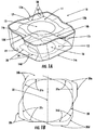
- FIG. 1A illustrates one non-limiting embodiment of a double-sided cutting insert in accordance with the present invention.
- a double-sided cutting insert 10 is shown in Fig. 1A .
- the double-sided cutting insert 10 of Figure 1A comprising a top side or face 11 and a bottom side or face 12, has eight cutting edges represented by reference numerals 13a, 13b, 13c, 13d for the top side or face 11, and 14a, 14b, 14c, 14d for the bottom side or face 12.
- the top side 11 and the bottom side 12 comprise an external profile that is different for each side.
- the chip groove geometry for the top side 11 and the bottom side 12 also may be different for each side. Additionally, the positioning of the insert pocket locations can optimize the final cutting geometries.
- the top side 11 of the double-sided cutting insert 10 includes a center hole 15 bored entirely through the double-sided cutting insert 10 (as shown on top side 11), a top peripheral cutting edge 13a, and top chip grooves 17 located between the top peripheral cutting edge 13a and the top edges 18 of the top side 11.
- a screw may be inserted through center hole 15 of the double-sided cutting insert 10 and into a threaded bore (not shown) on a surface of the cutting insert pocket, thereby retaining the insert in the pocket.
- the bottom side 12 of the double-sided cutting insert 10 includes a center hole 16 as shown in bottom side 12, a bottom peripheral cutting edge 14d, and bottom chip grooves 19 located between the bottom peripheral cutting edge 14d and the bottom edges 20 of the bottom side 12.
- the external profiles of both the top side 11 and the bottom side 12 have been extracted from the double-sided cutting insert 10 of Fig. 1A and have been superimposed in Fig. 1B as a top view.
- the external profile of the top side 11 is indicated as solid lines in Fig. 1B .
- the top view illustrates the top side 11 comprising four sets of cutting edges 30a, 30b, 30c, and 30d, and is indexable with 90 degrees rotation about the center 32 of the inscribed circle 33.
- FIG. 1B comprises four sets of cutting edges 31 a, 31 b, 31 c, and 31 d, and is indexable with 90 degrees rotation about the center axis 32 of the same inscribed circle 33.
- the inscribed circle 33 may be etched onto the top side 11 shown in Figure 1B
- the inscribed circle 33 is an imaginary circle.
- the inscribed circle is a tool used to define the diameter or radius of the top or bottom face of a cutting insert and is a conventional way of characterizing the size of the insert.
- Top side 11 and bottom side 12 are defined by the same inscribed circle 33.
- the number of cutting edges and chip grooves may vary in a given double-sided insert, yet are still within the scope of the present invention.
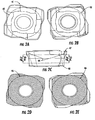
- Figures 2A, 2B, 2C, 2D, and 2E further illustrate a double-sided cutting insert 41 having an inscribed circle 42, 43, 45, 46.
- Figure 2A is a top view
- Figure 2B is a bottom view
- Figure 2C is a side view of the cutting insert 41.
- the inscribed circle 42 shown in Figure 2A is the largest circle that can be fully inscribed into the external profile of the top side of the double-sided cutting insert 41 and has the same diameter or radius of the circle in inches or SI units as the inscribed circle 43 shown in Figure 2B , which is the largest circle that can be inscribed into the external profile of the bottom side of the double-sided cutting insert 41.
- FIG. 2C two parallel lines 44 representing the inscribed circle extend all the way from the top side 47 to the bottom side 48 of the double-sided cutting insert 41. Furthermore, two sectioned views taken from E-E and F-F in Figure 2C are shown in Figure 2D and Figure 2E , respectively, where both the inscribed circles 45 and 46 have the same diameter as inscribed circles 42 and 43 in Figure 2A, Figure 2B, and Figure 2C .
- Figures 3A, 3B, 3C, 3D, and 3E illustrate differences between the chip groove geometry on the top and bottom sides of the double-sided cutting insert 51.
- Four sectioned views, A-A in Figure 3B , B-B in Figure 3C , C-C in Figure 3D and D-D in Figure 3E illustrate the chip groove profile of the double-sided cutting insert 51 in Figure 3A .
- the chip groove geometries 52, 53, 54, 55, 56, 57, 58, 59 differ in terms of groove profile and groove width (in millimeters as shown) from section to section.
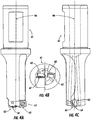
- Figures 4A, 4B, and 4C schematically depict a drilling tool system comprising a tool holder 61 comprising two identical double-sided cutting inserts 62 and 63, wherein each tool insert is constructed in accordance with the present invention.
- Figure 4A is a front view of a drilling tool system comprising a tool holder including two identical double-sided cutting inserts in accordance with the present invention.
- Figure 4B is an end view of the working end of a drilling tool system comprising a tool holder including two identical double-sided cutting inserts in accordance with the present invention.
- the cutting insert 62 is positioned with its cutting edge passing through the center axis 66 of the tool holder 61, and the cutting edge 64 on the top side 67 is an engaging cutting edge.
- an "engaging" cutting edge is the cutting edge that is positioned in the cutting insert pocket to contact or “engage” the workpiece when the tool is used. Because the insert is indexable, the insert could be removed (by removing a retention screw or the like) and then rotated in the insert pocket and re-secured, thereby positioning a new cutting edge so that it will contact the workpiece when the tool is used.
- the cutting insert 63 positioned at the periphery of the tool holder 61 and the cutting edge 65 on the bottom side 68 is an engaging cutting edge. In drilling operations, the cutting insert 62 is also referred to as the center drill insert and the cutting insert 63 is referred to as the peripheral drill insert.
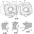
- Figure 5A further illustrates the working of two double-sided cutting inserts, 71 and 72, in a drilling tool system.
- the double-sided cutting inserts 71 and 72 are identical.
- the two identical cutting inserts 71 and 72 are positioned as illustrated in Figure 4A , but the tool holder 61 (not shown) is removed in this view.
- the cutting insert 71 is positioned as a center drill insert, with its top side cutting edge 74 positioned as an engaging cutting edge, and cutting insert 71 rotates about the tool holder center axis 73 during the drilling operation and creates the cutting passage 78 as indicated by dashed lines.
- the same principle applies to the cutting insert 72, which is positioned as a peripheral drill insert, and which creates the cutting passage 77 by its bottom side cutting edge 75 after rotating about the tool holder center axis 73.
- the drilling diameter As shown in Figure 5A , the drilling diameter, indicated as DD, which is the diameter of the hole produced, is measured from point P3 to point P4 in Figure 5A , which are the two outermost points for the diameter.
- the drill profiles formed by the center drill insert 71 are from point P1 to point P0 and then from point P0 to point P2 as measured by A2 in Figure 5A .
- the drill profiles formed by the peripheral drill insert 72 are from point P4 to point P1 and then from point P2 to point P3 as measured by A1 and A3, respectively, in Figure 5A .
- FIG. 5B, 5C, and 5D demonstrate that different chip groove geometries are applied at different locations along the peripheral cutting edge to generate different positive cutting actions between point P3 and point P4 in Figure 5A .
- FIG. 5B, 5C, and 5D demonstrate that different chip groove geometries are applied at different locations along the peripheral cutting edge to generate different positive cutting actions between point P3 and point P4 in Figure 5A .
- there are distinct differences among the three sectioned views which are provided as representative examples.
- Figures 5B, 5C, and 5D also show that the empty space formed by the chip groove edges 85 and 95 and the dashed lines 96 in section E-E for the peripheral drill insert 72 is smaller than that for the center drill insert 71 as formed by chip groove edges 81 and 91 and the dashed lines 92 in section C-C, and by chip groove edges 83 and 93 and the dashed lines 94 in section D-D.
- This difference is a result of it being more difficult to evacuate drilling chips produced at the center than at the periphery of the hole during drilling operations. Therefore, a larger empty space above the chip groove is needed for the center drill insert 71 than for the peripheral drill insert 72 in order to effectively evacuate the chips produced and in order to prevent those chips from becoming jammed between the drilling tool holder and the hole being drilled.
- Figures 6A and 6B show that the bottom profile of the hole 101 within a workpiece 102 is uniquely formed by the two identical double-sided cutting inserts 71 and 72 shown in Figure 5A .
- Figure 6A demonstrates how the profile is formed.
- Figure 6B shows an extracted profile of the hole 101 for clarification purposes. Due to the unique shape of embodiments of the double-sided insert of the present invention (i.e., its rugged and non-tangent profile), drilling with the double-sided insert aids in breaking chips into more numerous and smaller segments.
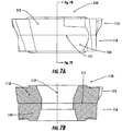
- FIGS 7A and 7B depict a non-limiting embodiment of a double-sided cutting insert 110 in accordance with the present invention constructed as a composite cemented carbide cutting insert.
- the double-sided cutting insert 110 comprises either two different cemented carbide materials 113 and 114 or the same cemented carbide material but with different cemented carbide grades 113 and 114, being separated by the line 111. Since the top portion 115 of the cutting insert 110 functions as a center drill insert, a cemented carbide material or grade possessing greater impact resistance may be used in that portion. Since the bottom portion 116 of the cutting insert 110 functions as a periphery drill insert, a cemented carbide material or grade having a greater wear resistance may be used in that portion.
- Figure 7A illustrates a side view of a non-limiting embodiment of a double-sided cutting insert in accordance with the present invention
- Figure 7B shows a sectioned view G-G through the center hole axis 112 illustrating the cutting insert's composite construction comprising two different cemented carbide materials.
- Typical manufacturing processes for making composite double-sided inserts include pressing two different carbide materials in a mold, followed by sintering and grinding the pressed insert, and a subsequent coating step that provides a hard metal coating over the cutting insert.
- the hard metal coating is an extremely thin (optimally in the range of microns) coating of a metallic alloy that is applied in order to improve wear resistance.
- PVD physical vapor deposition
- CVD chemical vapor deposition
- Typical PVD coatings include TiN, TiAlN, TiCN, TiAlN+C, and typical CVD coatings include TiN, TiCN, Al 2 O 3 , TiN-HfCN-Tin, TiN-TiCN-TiN.
- the cutting insert shown in Figures 7A and 7B provides improved machining performance through an optimized combination of cutting geometry and cemented carbide grade on different sides of the identical double-sided cutting insert.
- the double-sided cutting inserts of the present invention preferably comprise eight cutting edges and have different chip groove geometries between top and bottom sides. Such inserts may be adapted for hole making applications. These adaptations may be designed with a wide range of geometric features.
- the double-sided cutting inserts described herein may or may not be of conventional size and are capable of being adapted for conventional use in a variety of drilling applications.
- top and bottom faces of certain embodiments of double-sided cutting inserts according to the present invention can provide an optimized combination of profile, geometry, and cemented carbide grade for each side, resulting in a considerable improvement in cutting performance. This is a significant improvement over existing double-sided cutting inserts that have an identical top and bottom face.
- Embodiments of the double-sided cutting insert provided in this invention also provide significant cost reduction. Significant benefits in terms of improved machining performance can be achieved by a composite construction through the optimized combination of cutting geometry and cemented carbide grade on different faces of the cutting insert to adapt to different cutting actions in hole drilling.
Landscapes
- Engineering & Computer Science (AREA)
- Mechanical Engineering (AREA)
- Drilling Tools (AREA)
Applications Claiming Priority (2)
| Application Number | Priority Date | Filing Date | Title |
|---|---|---|---|
| US12/431,384 US9586264B2 (en) | 2009-04-28 | 2009-04-28 | Double-sided cutting insert for drilling tool |
| PCT/US2010/030358 WO2010126693A1 (en) | 2009-04-28 | 2010-04-08 | Double-sided cutting insert for drilling tool |
Publications (3)
| Publication Number | Publication Date |
|---|---|
| EP2424697A1 EP2424697A1 (en) | 2012-03-07 |
| EP2424697B1 EP2424697B1 (en) | 2016-02-17 |
| EP2424697B2 true EP2424697B2 (en) | 2021-03-31 |
Family
ID=42272487
Family Applications (1)
| Application Number | Title | Priority Date | Filing Date |
|---|---|---|---|
| EP10714742.3A Active EP2424697B2 (en) | 2009-04-28 | 2010-04-08 | Double-sided cutting insert for drilling tool |
Country Status (10)
| Country | Link |
|---|---|
| US (1) | US9586264B2 (enExample) |
| EP (1) | EP2424697B2 (enExample) |
| JP (1) | JP5647671B2 (enExample) |
| CN (1) | CN102458739B (enExample) |
| BR (1) | BRPI1014367A2 (enExample) |
| CA (1) | CA2757975A1 (enExample) |
| MX (1) | MX2011011001A (enExample) |
| RU (1) | RU2524290C2 (enExample) |
| TW (1) | TW201041678A (enExample) |
| WO (1) | WO2010126693A1 (enExample) |
Families Citing this family (47)
| Publication number | Priority date | Publication date | Assignee | Title |
|---|---|---|---|---|
| US7220083B2 (en) * | 2003-10-15 | 2007-05-22 | Tdy Industries, Inc. | Cutting insert for high feed face milling |
| JP4965667B2 (ja) * | 2007-12-27 | 2012-07-04 | 京セラ株式会社 | ドリル |
| US7905689B2 (en) * | 2008-05-07 | 2011-03-15 | Tdy Industries, Inc. | Cutting tool system, cutting insert, and tool holder |
| US8491234B2 (en) * | 2009-02-12 | 2013-07-23 | TDY Industries, LLC | Double-sided cutting inserts for high feed milling |
| US7976250B2 (en) * | 2009-02-12 | 2011-07-12 | Tdy Industries, Inc. | Double-sided cutting inserts for high feed milling |
| US8807884B2 (en) | 2009-12-18 | 2014-08-19 | Kennametal Inc. | Tool holder for multiple differently-shaped cutting inserts |
| AT12700U1 (de) * | 2011-07-05 | 2012-10-15 | Ceratizit Austria Gmbh | Bohrer-schneideinsatz |
| KR101222291B1 (ko) | 2011-07-20 | 2013-01-15 | 대구텍 유한회사 | 드릴 공구 |
| EP2734328B1 (en) * | 2011-07-22 | 2018-03-07 | Kennametal India Limited | An indexable drill insert |
| DE102012012980B4 (de) | 2011-07-22 | 2019-10-17 | Kennametal India Ltd. | Bohrwerkzeug |
| DE102012014092B4 (de) | 2011-07-22 | 2020-12-17 | Kennametal India Ltd. | Indexierbarer Bohreinsatz sowie Bohrkörper mit indexierbarem Bohreinsatz |
| US9475134B2 (en) * | 2011-12-19 | 2016-10-25 | Iscar, Ltd. | Cutting insert and cutting tool |
| US8696264B2 (en) * | 2012-01-31 | 2014-04-15 | Kennametal Inc. | Modular cutting insert and method of making same |
| CN103447591B (zh) | 2012-05-28 | 2020-02-28 | 钴碳化钨硬质合金印度有限公司 | 四角形的可转位的钻头镶片 |
| US9011049B2 (en) | 2012-09-25 | 2015-04-21 | Kennametal Inc. | Double-sided cutting inserts with anti-rotation features |
| US9283626B2 (en) | 2012-09-25 | 2016-03-15 | Kennametal Inc. | Double-sided cutting inserts with anti-rotation features |
| US10124415B2 (en) | 2013-01-23 | 2018-11-13 | Kennametal India Limited | Indexable drill insert and rotary cutting tool employing same |
| KR101519747B1 (ko) * | 2013-12-09 | 2015-05-12 | 한국야금 주식회사 | 인덱서블 드릴용 절삭인서트 |
| US9421611B2 (en) * | 2014-03-07 | 2016-08-23 | Kennametal Inc. | Composite cutting insert and method of making same |
| DE102015213016A1 (de) * | 2014-07-25 | 2016-01-28 | Kennametal India Limited | Indexierbare Einsätze und diese enthaltende Bohrer |
| EP3034214A1 (en) * | 2014-12-19 | 2016-06-22 | Pramet Tools, S.R.O. | Drill and drill insert with chipbreaker protrusions |
| WO2016136949A1 (ja) * | 2015-02-26 | 2016-09-01 | 京セラ株式会社 | インサート、ドリル及びそれを用いた切削加工物の製造方法 |
| CN104887060B (zh) * | 2015-06-25 | 2018-05-25 | 武汉苏泊尔炊具有限公司 | 不粘炊具及不粘炊具的制作方法 |
| USD778330S1 (en) | 2015-07-16 | 2017-02-07 | Kennametal Inc. | Double-sided tangential cutting insert |
| US9981323B2 (en) * | 2015-07-16 | 2018-05-29 | Kennametal Inc. | Double-sided tangential cutting insert and cutting tool system using the same |
| USD777230S1 (en) | 2015-07-16 | 2017-01-24 | Kennametal Inc | Double-sided tangential cutting insert |
| KR101814642B1 (ko) * | 2015-11-04 | 2018-01-03 | 한국야금 주식회사 | 고이송 양면형 절삭 인서트 및 이를 장착한 절삭 공구 |
| US10183333B2 (en) * | 2016-02-03 | 2019-01-22 | Iscar, Ltd. | Circular cutting insert having non-circular peripheral edge |
| JP2018051717A (ja) * | 2016-09-30 | 2018-04-05 | 株式会社タンガロイ | 切削インサート |
| KR102034490B1 (ko) * | 2016-12-27 | 2019-10-21 | 미츠비시 히타치 쓰루 가부시키가이샤 | 절삭 인서트 및 날끝 교환식 회전 절삭 공구 |
| DE112017006379T5 (de) * | 2017-07-12 | 2019-08-29 | Beijing Worldia Diamond Tools Co., Ltd. | Wendeplanfräsklinge und Planfräsmesserkopf unter Verwendung dieser Klinge |
| KR102386942B1 (ko) * | 2017-08-23 | 2022-04-14 | 대구텍 유한책임회사 | 드릴용 절삭 인서트 |
| CN109158665B (zh) * | 2018-08-14 | 2020-02-04 | 株洲钻石切削刀具股份有限公司 | 可转位钻孔刀具 |
| CN112077370B (zh) | 2019-06-13 | 2024-10-01 | 肯纳金属印度有限公司 | 可转位钻头刀片 |
| CN112077369A (zh) | 2019-06-13 | 2020-12-15 | 肯纳金属印度有限公司 | 可转位钻头刀片 |
| CN112388033B (zh) | 2019-08-14 | 2024-10-25 | 肯纳金属印度有限公司 | 可转位钻头刀片 |
| DE102019130940A1 (de) * | 2019-10-25 | 2021-04-29 | Gühring KG | Verfahren zur Herstellung einer Wendeschneidplatte sowie ein zerspanendes Werkzeug |
| RU2714563C1 (ru) * | 2019-12-05 | 2020-02-18 | Общество с ограниченной ответственностью "Сборные конструкции инструмента, фрезы Москвитина" | Многогранная двухсторонняя режущая пластина и фреза для ее использования |
| DE102020117101A1 (de) | 2020-06-29 | 2021-12-30 | Kennametal Inc. | Schneideinsatz und Zerspanungswerkzeug |
| USD1009108S1 (en) | 2020-09-21 | 2023-12-26 | Kyocera Unimerco Tooling A/S | Drill |
| CN114309682A (zh) * | 2020-09-30 | 2022-04-12 | 肯纳金属公司 | 切削刀片 |
| DE102021119229B4 (de) * | 2021-07-26 | 2023-11-30 | Audi Aktiengesellschaft | Fräswerkzeug |
| CN115703157A (zh) | 2021-08-17 | 2023-02-17 | 肯纳金属印度有限公司 | 具有冷却剂系统的可转位钻头组件 |
| USD1042566S1 (en) | 2021-12-31 | 2024-09-17 | Kennametal Inc. | Cutting insert |
| US11897043B2 (en) | 2021-12-31 | 2024-02-13 | Kennametal Inc. | Cutting inserts for use in milling tools |
| US11834909B1 (en) | 2023-02-27 | 2023-12-05 | Dynasty Energy Services, LLC | Cutter insert for a section milling tool |
| CN116748569A (zh) * | 2023-06-21 | 2023-09-15 | 浙江欣兴工具股份有限公司 | 一种可转位钻头的刀片组合及可转位钻头 |
Citations (12)
| Publication number | Priority date | Publication date | Assignee | Title |
|---|---|---|---|---|
| US3490117A (en) † | 1967-01-20 | 1970-01-20 | Karl Hertel | Tool holder |
| US3636602A (en) † | 1969-07-11 | 1972-01-25 | Frank Owen | Cutting tools |
| FR2236592A1 (en) † | 1973-07-11 | 1975-02-07 | Simonot Jean | Composite boring tool - has cutting edges of different materials at different diameters |
| US4294566A (en) † | 1980-06-16 | 1981-10-13 | Carmet Company | Eight edge positive chip control insert |
| US4597695A (en) † | 1985-03-11 | 1986-07-01 | Ingersoll Cutting Tool Company | Face milling apparatus with eight-edged insert |
| US6862966B2 (en) † | 2001-06-13 | 2005-03-08 | Toledo Metal Spinning Company | Device to cut and deburr metal and method of use thereof |
| WO2007127109A2 (en) † | 2006-04-24 | 2007-11-08 | Valenite Llc | Side locking insert and material removal tool with same |
| JP2008018515A (ja) † | 2006-07-14 | 2008-01-31 | Mitsubishi Materials Corp | 切削インサート及び切削工具 |
| US20080226943A1 (en) † | 2007-03-16 | 2008-09-18 | Tdy Industries, Inc. | Composite Articles |
| US20080273931A1 (en) † | 2005-11-15 | 2008-11-06 | Spitzenberger Konrad | Milling cutter and a cutting insert therefor |
| WO2010114201A1 (en) † | 2009-04-02 | 2010-10-07 | Taegutec. Ltd | Cutting insert for the dual purpose of roughing and finishing |
| EP2412462A1 (en) † | 2009-03-27 | 2012-02-01 | Kyocera Corporation | Cutting insert, cutting tool, and method of cutting material to be cut using the cutting tool |
Family Cites Families (216)
| Publication number | Priority date | Publication date | Assignee | Title |
|---|---|---|---|---|
| GB320809A (en) | 1928-12-05 | 1929-10-24 | Cammell Laird & Co Ltd | Improvements in or relating to turning and boring tools |
| GB951624A (en) | 1959-06-17 | 1964-03-11 | Sandvikens Jernverks Ab | Improvements in or relating to inserts for cutting tools |
| US3399442A (en) | 1966-09-08 | 1968-09-03 | Kennametal Inc | Cutting insert |
| US3557416A (en) | 1968-08-16 | 1971-01-26 | Kennametal Inc | Cutting insert |
| US3621549A (en) | 1970-03-06 | 1971-11-23 | James O Billups | Cutting tool insert assembly |
| US3805349A (en) | 1970-03-30 | 1974-04-23 | Sumitomo Electric Industries | Throw-away insert for milling cutter |
| US3806713A (en) | 1971-10-21 | 1974-04-23 | Honeywell Inf Systems | Method and apparatus for maximizing the length of straight line segments approximating a curve |
| JPS4932280A (enExample) | 1972-07-22 | 1974-03-23 | ||
| FR2274386A1 (fr) * | 1974-06-14 | 1976-01-09 | Ugine Carbone | Plaquette de coupe avec brise-copeaux |
| JPS5950450B2 (ja) | 1976-02-25 | 1984-12-08 | ダイジヱツト工業株式会社 | スロ−アウエイチツプ |
| FR2364724A1 (fr) | 1976-09-17 | 1978-04-14 | Walter Gmbh Montanwerke | Plaquette de coupe indexable pour outil de fraisage, et outil de fraisage equipe de telles plaquettes |
| SU814573A1 (ru) | 1978-07-31 | 1981-03-25 | Ярославский Политехническийинститут | Многопозиционна режуща пласти-HA |
| SU804239A1 (ru) | 1979-04-18 | 1981-02-15 | Куйбышевский Политехнический Инсти-Тут Им.B.B.Куйбышева | Режущий инструмент |
| US4274766A (en) | 1979-11-28 | 1981-06-23 | The Valeron Corporation | Cutter assembly for broaching |
| US4292365A (en) | 1980-01-21 | 1981-09-29 | Owens-Corning Fiberglas Corporation | Polymeric mats having continuous filaments with an asymmetrical cross-sectional shape |
| US4294565A (en) | 1980-03-06 | 1981-10-13 | General Electric Company | Indexable finishing insert for a milling cutter |
| US4395186A (en) | 1980-08-07 | 1983-07-26 | Turtle Tractor Company | Vehicle for tending low growing vegetation |
| US4412763A (en) * | 1981-01-21 | 1983-11-01 | Metal Cutting Tools, Inc. | Drill with single cutter |
| US4595322A (en) | 1981-08-10 | 1986-06-17 | Burke Clement | Spade drill bit |
| DE3200191A1 (de) | 1982-01-07 | 1983-07-14 | Otto 8961 Reicholzried Zettl | "fraeswerkzeug" |
| DE3204210C2 (de) | 1982-02-08 | 1986-04-03 | Stellram GmbH, 6056 Heusenstamm | Bohrwerkzeug für metallische Werkstoffe |
| SE452271B (sv) | 1982-04-01 | 1987-11-23 | Sandvik Ab | Sker och verktyg for spanskerande bearbetning |
| US4659264A (en) | 1982-07-06 | 1987-04-21 | Kennametal Inc. | Drill and indexable carbide insert therefor |
| JPS59214501A (ja) | 1983-05-23 | 1984-12-04 | Toshiba Corp | 切削工具 |
| JPS6022218U (ja) | 1983-07-20 | 1985-02-15 | 住友電気工業株式会社 | スロ−アウエイチツプ |
| SU1278110A1 (ru) | 1984-01-31 | 1986-12-23 | Государственное Проектное Конструкторско-Технологическое Бюро Машиностроения Научно-Производственного Объединения "Технолог" | Инструментальна головка |
| JPH0131371Y2 (enExample) | 1985-06-06 | 1989-09-26 | ||
| DE3618574C2 (de) | 1985-06-06 | 1989-11-02 | Mitsubishi Kinzoku K.K., Tokio/Tokyo, Jp | Positiv-wendeschneidplatte |
| SE456893B (sv) * | 1985-06-17 | 1988-11-14 | Sandvik Ab | Verktyg med loedda skaer foer spaanavskiljande bearbetning |
| JPH0357382Y2 (enExample) | 1986-05-16 | 1991-12-27 | ||
| US4679968A (en) | 1985-06-28 | 1987-07-14 | Mitsubishi Kinzoku Kabushiki Kaisha | Indexable cutter insert |
| SE448431B (sv) | 1985-07-03 | 1987-02-23 | Santrade Ltd | Vendsker for spanavskiljande bearbetning |
| JPS6239106A (ja) * | 1985-08-12 | 1987-02-20 | Toshiba Corp | 植刃式正面フライスの超硬チツプ |
| JPH0656387B2 (ja) | 1986-01-27 | 1994-07-27 | 株式会社リコー | 回転方向判別方式 |
| CH667407A5 (fr) | 1986-03-27 | 1988-10-14 | Stellram Sa | Fraise a plaquettes de coupe amovibles. |
| US4760548A (en) | 1986-06-13 | 1988-07-26 | International Business Machines Corporation | Method and apparatus for producing a curve image |
| JPH0782554B2 (ja) | 1986-09-10 | 1995-09-06 | フアナツク株式会社 | 曲面加工方法 |
| DE3807119A1 (de) | 1987-03-04 | 1988-09-15 | Mitsubishi Metal Corp | Kugelstirnfraeser |
| US4919573A (en) | 1987-09-22 | 1990-04-24 | Mitsubishi Kinzoku Kabushiki Kaisha | Ball end mill |
| SU1504006A1 (ru) | 1987-11-30 | 1989-08-30 | В.Г. Чернавский, В.Г. Дигтенко, А.И. Дронов и Т.Б. Грищенко | Режуща пластина |
| IL93883A (en) | 1989-04-12 | 1993-02-21 | Iscar Ltd | Cutting insert for a milling cutting tool |
| US5094572A (en) | 1989-12-04 | 1992-03-10 | Thomas Grismer | Spade drill for hard material |
| ATE102517T1 (de) * | 1989-12-15 | 1994-03-15 | Safety Sa | Bohrer und schneideinsatz dafuer. |
| US5137398A (en) | 1990-04-27 | 1992-08-11 | Sumitomo Electric Industries, Ltd. | Drill bit having a diamond-coated sintered body |
| GB9010769D0 (en) | 1990-05-14 | 1990-07-04 | Iscar Hartmetall | Cutting insert |
| US5244318A (en) * | 1990-07-04 | 1993-09-14 | Mitsubishi Materials Corporation | Throwaway insert and cutting tool therefor |
| US5333972A (en) | 1990-10-04 | 1994-08-02 | Valenite Inc. | Special boring insert |
| US5232319A (en) | 1990-10-25 | 1993-08-03 | Iscar Ltd. | Insert for a milling cutter |
| SE500310C2 (sv) | 1990-12-03 | 1994-05-30 | Sandvik Ab | Skär och verktyg för skalsvarvning |
| US5092718A (en) | 1990-12-10 | 1992-03-03 | Metal Cutting Tools Corp. | Drill with replaceable cutting inserts |
| SE467727B (sv) | 1991-01-28 | 1992-09-07 | Sandvik Ab | Borr med minst tvaa skaer, samt med symmetrisk borrspets och olika laanga skaereggar |
| JP3057781B2 (ja) | 1991-03-07 | 2000-07-04 | 三菱マテリアル株式会社 | スローアウェイチップ |
| US5145294A (en) | 1991-03-15 | 1992-09-08 | National Carbide Outlet, Inc. | Milling cutter capable of using indexable inserts of various shapes |
| US5338135A (en) | 1991-04-11 | 1994-08-16 | Sumitomo Electric Industries, Ltd. | Drill and lock screw employed for fastening the same |
| JPH04315510A (ja) | 1991-04-11 | 1992-11-06 | Sumitomo Electric Ind Ltd | ドリル |
| US5408598A (en) | 1991-05-23 | 1995-04-18 | International Business Machines Corporation | Method for fast generation of parametric curves employing a pre-calculated number of line segments in accordance with a determined error threshold |
| DE4118065C2 (de) | 1991-06-01 | 1994-09-01 | Krupp Widia Gmbh | Vieleckiger oder runder Schneideinsatz |
| DE4118070C2 (de) | 1991-06-01 | 1995-02-09 | Widia Heinlein Gmbh | Werkzeug für die spanende Bearbeitung |
| US5377116A (en) | 1991-07-01 | 1994-12-27 | Valenite Inc. | Method and system for designing a cutting tool |
| US5226761A (en) | 1991-09-27 | 1993-07-13 | Iscar Ltd. | Metal cutting insert and metal cutting tool utilizing the metal cutting insert |
| US5203649A (en) | 1991-10-07 | 1993-04-20 | Gte Valentine Corporation | High productivity, high metal removal rate insert |
| DE4141368A1 (de) | 1991-12-14 | 1993-06-17 | Krupp Widia Gmbh | Schneideinsatz |
| SE502243C2 (sv) | 1991-12-17 | 1995-09-25 | Sandvik Ab | Skivfräs med skärkassetter |
| RU2022727C1 (ru) | 1991-12-20 | 1994-11-15 | Акционерное общество открытого типа "Белгородский завод фрез" | Фреза |
| EP0551543A1 (en) | 1992-01-16 | 1993-07-21 | Hewlett-Packard GmbH | Method of modifying a geometric object and computer aided design system |
| SE502541C2 (sv) | 1992-02-05 | 1995-11-06 | Sandvik Ab | Spånavskiljande skär med exakta lägesbestämmande mått, samt förfarande för dess framställning |
| CA2062213C (en) | 1992-03-03 | 1996-07-16 | Alfonso Minicozzi | Indexable cutting insert for rotary cutting tools |
| JPH05285708A (ja) | 1992-04-10 | 1993-11-02 | Sumitomo Electric Ind Ltd | 接合スローアウェイチップおよびその製造方法 |
| JPH0615517A (ja) | 1992-07-01 | 1994-01-25 | Sumitomo Electric Ind Ltd | スローアウェイチップ及び正面フライスカッタ |
| IL103115A (en) | 1992-09-09 | 1996-09-12 | Iscar Ltd | Milling cutter insert |
| US5346336A (en) | 1992-11-04 | 1994-09-13 | Sandvik, Inc. | Metal-cutting insert having a round cutting edge |
| AT397626B (de) | 1992-11-20 | 1994-05-25 | Plansee Tizit Gmbh | Schneidwerkzeug mit integrierter kühlmittelzufuhr |
| DE4239236C2 (de) | 1992-11-21 | 1997-06-26 | Widia Gmbh | Schneideinsatz |
| JPH06218618A (ja) | 1993-01-21 | 1994-08-09 | Mitsubishi Materials Corp | スローアウェイチップ |
| SE500722C2 (sv) | 1993-01-27 | 1994-08-15 | Sandvik Ab | Skär med vriden spånyta |
| JP3196394B2 (ja) | 1993-02-01 | 2001-08-06 | 三菱マテリアル株式会社 | スローアウェイチップ |
| US5725334A (en) | 1993-03-29 | 1998-03-10 | Widia Gmbh | Cutting insert |
| EP0625395B1 (de) | 1993-05-10 | 1995-04-19 | STELLRAM GmbH | Bohrwerkzeug für metallische Werkstoffe |
| SE508387C2 (sv) | 1993-05-26 | 1998-10-05 | Sandvik Ab | Rundskär |
| ES2085840T3 (es) | 1993-06-25 | 1997-06-16 | Kennametal Inc | Geometria de esquina de pieza postiza para rugosidad de superficie mejorada. |
| JPH077809U (ja) * | 1993-06-30 | 1995-02-03 | ダイジ▲ェ▼ット工業株式会社 | 転削工具 |
| US5388932A (en) | 1993-09-13 | 1995-02-14 | Kennametal Inc. | Cutting insert for a milling cutter |
| WO1995007783A1 (de) | 1993-09-13 | 1995-03-23 | Widia Gmbh | Schneideinsatz |
| JPH0733525U (ja) | 1993-12-03 | 1995-06-20 | 三菱マテリアル株式会社 | スローアウェイ式切削工具 |
| JP3166022B2 (ja) | 1993-12-28 | 2001-05-14 | 三菱マテリアル株式会社 | スローアウェイチップおよびその製造方法 |
| DE9400327U1 (de) | 1994-01-11 | 1994-03-03 | Krupp Widia Gmbh, 45145 Essen | Mehrschneidige Wendeschneidplatte |
| DE4400538A1 (de) | 1994-01-11 | 1995-07-13 | Gustav Werthwein | Fräswerkzeug |
| CA2180547C (en) | 1994-01-14 | 2005-03-15 | Ingemar Hessman | Indexable insert for finish milling and cutter body therefor |
| IL109054A (en) * | 1994-03-21 | 1998-07-15 | Iscar Ltd | Cutting insert |
| SE509224C2 (sv) | 1994-05-19 | 1998-12-21 | Sandvik Ab | Vändskär |
| JPH0839329A (ja) | 1994-07-29 | 1996-02-13 | Mitsubishi Materials Corp | スローアウェイチップ |
| DE4430171C2 (de) | 1994-08-25 | 1996-08-14 | Walter Ag | Formschlüssig gesicherte Schneidplatte |
| IL110785A (en) | 1994-08-25 | 1998-04-05 | Iscar Ltd | Put a spinner for a rotary milling tool |
| IL111367A0 (en) | 1994-10-23 | 1994-12-29 | Iscar Ltd | An exchangeable cutting insert |
| SE505511C2 (sv) | 1994-12-15 | 1997-09-08 | Sandvik Ab | Fräskropp samt förfarande för tillverkning av denna |
| JPH08174327A (ja) | 1994-12-27 | 1996-07-09 | Toshiba Tungaloy Co Ltd | 正面フライス用のスローアウェイチップ |
| US5791833A (en) | 1994-12-29 | 1998-08-11 | Kennametal Inc. | Cutting insert having a chipbreaker for thin chips |
| US5542795A (en) | 1995-01-30 | 1996-08-06 | Kennametal Inc. | Plunge and face milling cutter with universal insert seats |
| JP3109561B2 (ja) | 1995-03-08 | 2000-11-20 | 住友電気工業株式会社 | スローアウェイチップ及び切削工具 |
| JP3564778B2 (ja) | 1995-03-10 | 2004-09-15 | マツダ株式会社 | 金型の切削加工方法 |
| US5807031A (en) | 1995-03-10 | 1998-09-15 | Mitsubishi Materials Corp. | Throw-away tip and throw-away type cutter |
| JPH08261167A (ja) | 1995-03-24 | 1996-10-08 | Toyota Autom Loom Works Ltd | 圧縮機 |
| US5562370A (en) | 1995-03-27 | 1996-10-08 | Kennametal Inc. | Insert having sinusoidal undulations for ball nose end mill |
| RU2354U1 (ru) * | 1995-04-06 | 1996-07-16 | Юрий Иванович Конча | Пластина режущая двухсторонняя |
| DE19516893A1 (de) | 1995-05-09 | 1996-11-14 | Widia Gmbh | Schneideinsatz und Fräswerkzeug |
| SE506679C2 (sv) | 1995-06-21 | 1998-01-26 | Seco Tools Ab | Skärverktyg, företrädesvis för fräsning |
| JP3634909B2 (ja) | 1995-11-27 | 2005-03-30 | 京セラ株式会社 | ドリルインサート |
| JPH09216113A (ja) | 1996-02-13 | 1997-08-19 | Sumitomo Electric Ind Ltd | スローアウェイチップおよび切削工具 |
| DE19624342C1 (de) | 1996-06-19 | 1997-12-11 | Walter Ag | Schneidplatte und Fräser, insbesondere Kugelstirnfräser oder Kopierfräser |
| IL118797A (en) | 1996-07-05 | 1999-10-28 | Iscar Ltd | Cutting insert |
| WO1998007539A1 (de) * | 1996-08-23 | 1998-02-26 | Widia Gmbh | Schneideinsatz zum bohren und bohrwerkzeug |
| IL119841A (en) | 1996-12-16 | 2000-02-29 | Iscar Ltd | Cutting inserts |
| US6100904A (en) | 1997-06-25 | 2000-08-08 | Adobe Systems Incorporated | Curvature smoothing |
| SE512253C2 (sv) | 1997-06-30 | 2000-02-21 | Sandvik Ab | Vändskär |
| JPH11129109A (ja) | 1997-10-31 | 1999-05-18 | Ngk Spark Plug Co Ltd | ドリルリーマチップ及びドリルリーマ工具 |
| IL123685A (en) * | 1998-03-16 | 2001-09-13 | Iscar Ltd | Modular cutting tool dispenser |
| SE512040C2 (sv) | 1998-05-06 | 2000-01-17 | Sandvik Ab | Vändskär för pinnfräsar |
| RU2138371C1 (ru) | 1998-06-26 | 1999-09-27 | Алтайский государственный технический университет им.И.И.Ползунова | Фреза |
| US5957635A (en) | 1998-08-21 | 1999-09-28 | Allied Machine & Engineering Corp. | Drill tool assembly |
| SE514032C2 (sv) | 1998-09-08 | 2000-12-11 | Seco Tools Ab | Verktyg och skär för fräsning |
| US6238133B1 (en) | 1998-10-20 | 2001-05-29 | Kennametal Pc Inc. | Anti-rotation mounting mechanism for round cutting insert |
| IL127175A (en) | 1998-11-20 | 2003-06-24 | Iscar Ltd | Cutting insert for mounting on a milling cutter |
| US6186705B1 (en) | 1999-02-23 | 2001-02-13 | Ingersoll Cutting Tool Company | Cutting insert with chip control |
| US6050752A (en) | 1999-03-19 | 2000-04-18 | Kennametal Inc. | Cutting insert |
| TW505551B (en) | 1999-04-29 | 2002-10-11 | Iscar Ltd | Cutting tool assembly and cutting insert therefor |
| JP3884884B2 (ja) | 1999-06-22 | 2007-02-21 | 東芝機械株式会社 | インコーナ切削加工方法および切削工具 |
| JP4465809B2 (ja) | 1999-07-09 | 2010-05-26 | 三菱マテリアル株式会社 | スローアウェイチップ |
| JP4562222B2 (ja) | 1999-07-30 | 2010-10-13 | 京セラ株式会社 | スローアウェイ式エンドミル |
| SE515070C2 (sv) | 1999-10-22 | 2001-06-05 | Sandvik Ab | Dubbelnegativt skär till verktyg för spånavskiljande bearbetning |
| US6270297B1 (en) | 2000-01-28 | 2001-08-07 | Ati Properties, Inc. | Cutting tools and drill inserts with chip control geometry |
| SE519575C2 (sv) | 2000-04-11 | 2003-03-18 | Sandvik Ab | Borrdkär för metallborrning |
| DE10018452A1 (de) | 2000-04-13 | 2001-10-25 | Widia Gmbh | Schneideinsatz |
| JP4576735B2 (ja) | 2000-05-23 | 2010-11-10 | 三菱マテリアル株式会社 | スローアウェイチップ及びスローアウェイ式カッタ |
| US6599061B1 (en) * | 2000-08-17 | 2003-07-29 | Kennametal Inc. | Cutting insert with radially aligned chip forming grooves |
| KR100387406B1 (ko) | 2000-08-29 | 2003-06-18 | 한국야금 주식회사 | 곡선 절인을 가진 절삭인서트 |
| US6508612B1 (en) | 2000-09-05 | 2003-01-21 | Kennametal Inc. | Milling cutter capable of using inserts of various geometrical shapes |
| US6684742B1 (en) | 2000-10-19 | 2004-02-03 | Keith Alan White | Machining apparatuses and methods of use |
| EP1205877A1 (en) | 2000-11-14 | 2002-05-15 | Honda R&D Europe (Deutschland) GmbH | Approximate fitness functions |
| SE520997C2 (sv) | 2001-01-09 | 2003-09-23 | Sandvik Ab | Vändbart frässkär med rillförsedd kopplingsyta mot hållaren och centralt materialparti för fästorgan |
| US6769844B2 (en) | 2001-01-10 | 2004-08-03 | Kennametal Inc. | Cutting insert and method of making the same |
| IL141089A (en) | 2001-01-25 | 2006-08-20 | Amir Satran | Cutting insert |
| JP4228557B2 (ja) | 2001-02-05 | 2009-02-25 | 三菱マテリアル株式会社 | スローアウェイチップ |
| JP2002301603A (ja) | 2001-04-02 | 2002-10-15 | Manabe Seisakusho:Kk | スローアウェイ切削チップ、切削チップホルダ及びスローアウェイ切削チップの位置決め方法 |
| US6540448B2 (en) | 2001-05-14 | 2003-04-01 | Ingersoll Cutting Tool Company | Cutting tool with improved insert seat arrangement for indexable cutting inserts |
| KR100916280B1 (ko) | 2001-05-25 | 2009-09-10 | 히타치 쓰루 가부시키가이샤 | 날끝 교환식 회전 공구 |
| US6503028B1 (en) | 2001-06-15 | 2003-01-07 | Sandvik Aktiebolag | Sintered cutting insert having center hole for clamp screw |
| IL144090A0 (en) * | 2001-07-02 | 2002-05-23 | Iscar Ltd | Cutting tool with two edge-on mounted inserts |
| JP4797292B2 (ja) | 2001-07-17 | 2011-10-19 | 株式会社タンガロイ | スローアウェイ式エンドミルおよび切刃チップ |
| US6623217B2 (en) | 2001-09-24 | 2003-09-23 | Valenite, Inc. | Indexable turning insert |
| IL145574A0 (en) | 2001-09-24 | 2002-06-30 | Iscar Ltd | Cutting tool and cutting insert therefor |
| SE523617C2 (sv) | 2001-10-01 | 2004-05-04 | Sandvik Ab | Skär för spånavskiljande bearbetning försedd med spånbrytande geometri |
| JP2003266232A (ja) | 2002-03-12 | 2003-09-24 | Sumitomo Electric Ind Ltd | 穴付きネガティブチップ及びそれを用いた刃先交換式カッタ |
| JP3775321B2 (ja) | 2002-03-20 | 2006-05-17 | 三菱マテリアル株式会社 | スローアウェイチップおよびスローアウェイ式切削工具 |
| JP3951766B2 (ja) | 2002-03-20 | 2007-08-01 | 三菱マテリアル株式会社 | スローアウェイチップおよびスローアウェイ式切削工具 |
| SE521579C2 (sv) | 2002-03-21 | 2003-11-11 | Sandvik Ab | Verktyg samt skär för spånavskiljande bearbetning |
| US20030206777A1 (en) | 2002-05-03 | 2003-11-06 | Gyllengahm Ulf Stefan | Metal cutting insert having straight cutting edge and curved abutment surface |
| SE525241C2 (sv) | 2002-05-29 | 2005-01-11 | Sandvik Ab | Borrverktygsats, borrverktyg samt indexerbart borrskär härför |
| US6811359B2 (en) | 2002-05-31 | 2004-11-02 | Kennametal Inc. | True helical cutter system |
| IL153252A0 (en) | 2002-06-04 | 2003-07-06 | Iscar Ltd | Tangential cutting insert and milling cutter |
| IL150015A (en) | 2002-06-04 | 2007-06-17 | Amir Satran | Cutting insert and milling cutter |
| DE10225070A1 (de) | 2002-06-06 | 2004-01-15 | Hilti Ag | Kernbohrkrone mit geometrisch definierten Schneidelementen |
| AT6205U1 (de) * | 2002-06-21 | 2003-06-25 | Plansee Tizit Ag | Schneideinsatz mit zwei gegenüberliegenden schneidköpfen |
| US6960049B2 (en) | 2002-06-25 | 2005-11-01 | Ngk Spark Plug Co., Ltd. | Insert, holder and cutting tool |
| SE525878C2 (sv) | 2002-10-10 | 2005-05-17 | Seco Tools Ab | Fräsverktyg och indexerbart skär med parallella sidor |
| IL153093A0 (en) | 2002-11-26 | 2003-06-24 | Iscar Ltd | Cutting insert and cutting tool |
| US6742969B1 (en) * | 2002-12-24 | 2004-06-01 | Kennametal Inc. | Milling cutter insert with chip control and milling cutter using the same |
| JP4121449B2 (ja) | 2003-01-16 | 2008-07-23 | 日本特殊陶業株式会社 | スローアウェイチップ及びバイト |
| JP2004230472A (ja) | 2003-01-28 | 2004-08-19 | Kyocera Corp | スローアウェイボールエンドミル |
| DE10312922B4 (de) | 2003-03-22 | 2006-02-16 | Walter Ag | Schneidplatte und Fräswerkzeug |
| JP4351460B2 (ja) | 2003-03-25 | 2009-10-28 | 京セラ株式会社 | スローアウェイエンドミル |
| US7722297B2 (en) | 2003-04-15 | 2010-05-25 | Tdy Industries, Inc. | Antirotation tool holder and cutting insert |
| DE10317760B4 (de) | 2003-04-17 | 2005-08-25 | Walter Ag | Fräswerkzeug und Schneidplatte für ein solches |
| KR100556681B1 (ko) | 2003-04-28 | 2006-03-07 | 대구텍 주식회사 | 다기능 절삭 가공용 툴홀더 조립체 |
| US7234899B2 (en) | 2003-05-19 | 2007-06-26 | Tdy Industries, Inc. | Cutting tool having a wiper nose corner |
| DE10326662A1 (de) | 2003-06-11 | 2005-01-05 | Sandvik Ab | Schneideinsatz zum Drehen und Fräsen |
| DE10346790A1 (de) * | 2003-10-08 | 2005-05-04 | Kennametal Widia Gmbh & Co Kg | Schneideinsatz |
| US7220083B2 (en) | 2003-10-15 | 2007-05-22 | Tdy Industries, Inc. | Cutting insert for high feed face milling |
| DE10361450A1 (de) | 2003-12-23 | 2005-07-28 | EMUGE-Werk Richard Glimpel GmbH & Co. KG Fabrik für Präzisionswerkzeuge | Schneidelement und Werkzeug mit wenigstens einem Schneidelement |
| IL160223A (en) | 2004-02-04 | 2008-11-26 | Carol Smilovici | Double-sided cutting insert and milling cutter |
| SE527851C2 (sv) | 2004-02-11 | 2006-06-20 | Sandvik Intellectual Property | Skärverktyg, skär samt del till skärverktyg med serrationskopplingsytor |
| FR2866583B1 (fr) | 2004-02-25 | 2007-04-20 | Safety | Plaquette de coupe a nombre limite de faces de cadrage |
| US7070363B2 (en) | 2004-07-15 | 2006-07-04 | Kennametal Inc. | Cutting insert for high-speed milling cutter |
| SE527617C8 (sv) | 2004-09-06 | 2006-06-13 | Sandvik Intellectual Property | Fräsverktyg, skär för fräsverktyg samt solitt fräsverktyg |
| US7325471B2 (en) | 2004-09-07 | 2008-02-05 | Kennametal Inc. | Toolholder and cutting insert for a toolholder assembly |
| SE527613C2 (sv) | 2004-10-15 | 2006-04-25 | Seco Tools Ab | Verktyg för skärande bearbetning med en underläggsplatta med urtagningar |
| US7452167B2 (en) | 2004-11-26 | 2008-11-18 | Kyocera Corporation | Cutting insert and milling tool |
| JP2006281391A (ja) * | 2005-04-01 | 2006-10-19 | Mitsubishi Materials Corp | インサート及びインサート着脱式穴あけ工具 |
| RU2318634C2 (ru) | 2005-04-13 | 2008-03-10 | Валентин Алексеевич Настасенко | Торцовая режущая, режуще-деформирующая и деформирующая фреза, рабочие пластины к ней и способ их изготовления, способ обработки деформирующей фрезой |
| KR100783795B1 (ko) | 2005-05-26 | 2007-12-07 | 주식회사 한국라임티비 | 핫-키 매핑 데이터에 대한 동적 갱신이 가능한 핫-키 관리서버와 디지털방송 수신 재생 장치 및 핫-키 매핑 데이터갱신 방법 |
| DE102005025815A1 (de) | 2005-06-02 | 2006-12-07 | Kennametal Widia Produktions Gmbh & Co. Kg | Schneideinsatz, insbesondere zur Kurbelwellenbearbeitung |
| IL169340A (en) | 2005-06-22 | 2010-04-29 | Gil Hecht | Cutting insert |
| IL169491A (en) | 2005-06-30 | 2009-06-15 | Carol Smilovici | Cutting insert |
| JP4231497B2 (ja) * | 2005-08-01 | 2009-02-25 | 住友電工ハードメタル株式会社 | 刃先交換式ドリル |
| JP4231496B2 (ja) * | 2005-08-01 | 2009-02-25 | 住友電工ハードメタル株式会社 | スローアウェイチップ |
| JP2007044782A (ja) | 2005-08-08 | 2007-02-22 | Sumitomo Electric Hardmetal Corp | スローアウェイチップ及びそれを用いたミーリングカッタ |
| US7687156B2 (en) * | 2005-08-18 | 2010-03-30 | Tdy Industries, Inc. | Composite cutting inserts and methods of making the same |
| SE529107C2 (sv) * | 2005-09-28 | 2007-05-02 | Seco Tools Ab | Fräs, fräskropp och vändskär där skäret har formen av en stympad pyramid |
| DE102006011581B4 (de) | 2006-03-10 | 2016-04-28 | Kennametal Widia Produktions Gmbh & Co. Kg | Schneideinsatz und Fräswerkzeug |
| SE530025C2 (sv) | 2006-06-21 | 2008-02-12 | Seco Tools Ab | Vändbart frässkär och verktyg med trigonformat tangentiellt monterat skär |
| SE530090C2 (sv) | 2006-06-27 | 2008-02-26 | Sandvik Intellectual Property | Planfrässkär med flera bågformiga deleggar och konvexa släppningsytor |
| CN101547764B (zh) | 2006-09-06 | 2011-04-06 | 特固克有限会社 | 切削刀片以及切削刀具 |
| CN200984661Y (zh) * | 2006-12-31 | 2007-12-05 | 株洲钻石切削刀具股份有限公司 | 可转位铣削刀片 |
| US7905687B2 (en) | 2007-01-16 | 2011-03-15 | Tdy Industries, Inc. | Cutting insert, tool holder, and related method |
| SE530808C2 (sv) | 2007-01-31 | 2008-09-16 | Sandvik Intellectual Property | Verktyg för spånavskiljande bearbetning, samt skär och grundkropp härför |
| IL182343A0 (en) | 2007-04-01 | 2007-07-24 | Iscar Ltd | Cutting insert and tool for milling and ramping at high feed rates |
| SE531250C2 (sv) | 2007-06-05 | 2009-02-03 | Sandvik Intellectual Property | Indexerbart hörnfrässkär |
| US7905689B2 (en) | 2008-05-07 | 2011-03-15 | Tdy Industries, Inc. | Cutting tool system, cutting insert, and tool holder |
| SE532742C2 (sv) * | 2008-05-13 | 2010-03-30 | Sandvik Intellectual Property | Frässkär med biegg snedställd i måttlig vinkel |
| DE102008037915B3 (de) | 2008-08-14 | 2009-08-13 | Kennametal Inc. | Wendeschneidplatte |
| US8491234B2 (en) | 2009-02-12 | 2013-07-23 | TDY Industries, LLC | Double-sided cutting inserts for high feed milling |
| US7976250B2 (en) | 2009-02-12 | 2011-07-12 | Tdy Industries, Inc. | Double-sided cutting inserts for high feed milling |
| SE533484C2 (sv) | 2009-02-20 | 2010-10-05 | Sandvik Intellectual Property | Roterbart verktyg för spånavskiljande bearbetning samt skär härför |
| KR101103216B1 (ko) | 2009-05-19 | 2012-01-05 | 대구텍 유한회사 | 원형 형상을 갖는 양면형 절삭 삽입체 및 이를 사용하는 절삭 공구 |
| SE534512C2 (sv) | 2009-06-24 | 2011-09-13 | Sandvik Intellectual Property | Verktyg för spånavskiljande bearbetning samt solitt indexerbart skär och solid grundkropp härför |
| US8573903B2 (en) | 2009-11-03 | 2013-11-05 | Kennametal Inc. | Round cutting insert with anti-rotation feature |
| US8657539B2 (en) | 2011-03-28 | 2014-02-25 | Kennametal Inc. | Round cutting insert with reverse anti-rotation feature |
-
2009
- 2009-04-28 US US12/431,384 patent/US9586264B2/en active Active
-
2010
- 2010-04-08 CN CN201080028947.3A patent/CN102458739B/zh active Active
- 2010-04-08 CA CA2757975A patent/CA2757975A1/en not_active Abandoned
- 2010-04-08 WO PCT/US2010/030358 patent/WO2010126693A1/en not_active Ceased
- 2010-04-08 BR BRPI1014367A patent/BRPI1014367A2/pt not_active IP Right Cessation
- 2010-04-08 JP JP2012508511A patent/JP5647671B2/ja not_active Expired - Fee Related
- 2010-04-08 RU RU2011148261/02A patent/RU2524290C2/ru not_active IP Right Cessation
- 2010-04-08 MX MX2011011001A patent/MX2011011001A/es not_active Application Discontinuation
- 2010-04-08 EP EP10714742.3A patent/EP2424697B2/en active Active
- 2010-04-28 TW TW099113541A patent/TW201041678A/zh unknown
Patent Citations (12)
| Publication number | Priority date | Publication date | Assignee | Title |
|---|---|---|---|---|
| US3490117A (en) † | 1967-01-20 | 1970-01-20 | Karl Hertel | Tool holder |
| US3636602A (en) † | 1969-07-11 | 1972-01-25 | Frank Owen | Cutting tools |
| FR2236592A1 (en) † | 1973-07-11 | 1975-02-07 | Simonot Jean | Composite boring tool - has cutting edges of different materials at different diameters |
| US4294566A (en) † | 1980-06-16 | 1981-10-13 | Carmet Company | Eight edge positive chip control insert |
| US4597695A (en) † | 1985-03-11 | 1986-07-01 | Ingersoll Cutting Tool Company | Face milling apparatus with eight-edged insert |
| US6862966B2 (en) † | 2001-06-13 | 2005-03-08 | Toledo Metal Spinning Company | Device to cut and deburr metal and method of use thereof |
| US20080273931A1 (en) † | 2005-11-15 | 2008-11-06 | Spitzenberger Konrad | Milling cutter and a cutting insert therefor |
| WO2007127109A2 (en) † | 2006-04-24 | 2007-11-08 | Valenite Llc | Side locking insert and material removal tool with same |
| JP2008018515A (ja) † | 2006-07-14 | 2008-01-31 | Mitsubishi Materials Corp | 切削インサート及び切削工具 |
| US20080226943A1 (en) † | 2007-03-16 | 2008-09-18 | Tdy Industries, Inc. | Composite Articles |
| EP2412462A1 (en) † | 2009-03-27 | 2012-02-01 | Kyocera Corporation | Cutting insert, cutting tool, and method of cutting material to be cut using the cutting tool |
| WO2010114201A1 (en) † | 2009-04-02 | 2010-10-07 | Taegutec. Ltd | Cutting insert for the dual purpose of roughing and finishing |
Non-Patent Citations (2)
| Title |
|---|
| "Modern Metal Cutting", 1 January 1996, SANDVIK COROMANT, article "Cemented Carbide", pages: 12 † |
| KLOCKE, F., KÖNIG, W.: "Fertigungsverfahren Drehen, Fräsen, Bohren", 2008, SPRINGER VERLAG, article "excerpt", pages: 456 † |
Also Published As
| Publication number | Publication date |
|---|---|
| CA2757975A1 (en) | 2010-11-04 |
| CN102458739A (zh) | 2012-05-16 |
| US9586264B2 (en) | 2017-03-07 |
| BRPI1014367A2 (pt) | 2016-04-05 |
| CN102458739B (zh) | 2015-02-25 |
| US20100272526A1 (en) | 2010-10-28 |
| WO2010126693A1 (en) | 2010-11-04 |
| RU2524290C2 (ru) | 2014-07-27 |
| EP2424697A1 (en) | 2012-03-07 |
| EP2424697B1 (en) | 2016-02-17 |
| JP5647671B2 (ja) | 2015-01-07 |
| TW201041678A (en) | 2010-12-01 |
| MX2011011001A (es) | 2012-01-25 |
| RU2011148261A (ru) | 2013-06-10 |
| JP2012525271A (ja) | 2012-10-22 |
Similar Documents
| Publication | Publication Date | Title |
|---|---|---|
| EP2424697B2 (en) | Double-sided cutting insert for drilling tool | |
| US6158304A (en) | Process for forming a center cutting end mill | |
| US7625161B1 (en) | Rotary cutting tool assembly and cutting insert and tool shank therefor | |
| US9333565B2 (en) | Rotary cutter | |
| US6929434B2 (en) | Rotary cutting tool | |
| EP1349689B1 (en) | Tool and toolholder for chip forming machining | |
| US5322394A (en) | Highly stiff end mill | |
| US8702357B2 (en) | Multi-piece drill head and drill including the same | |
| US6719501B2 (en) | Cemented carbide end mill | |
| US20100278603A1 (en) | Multi-Piece Drill Head and Drill Including the Same | |
| CN108526552B (zh) | 具有不相等的沟槽间距和不相等的后角的麻花钻 | |
| WO2006028886A1 (en) | Multiple-axis cutting toroidal end mill | |
| EP0213334A2 (en) | Cermet solid end mill | |
| EP1052367B1 (en) | Preform cutting elements for rotary drill bits | |
| JP4723302B2 (ja) | マシンリーマー | |
| JP2006281433A (ja) | インサート及び切削工具 | |
| JP4996278B2 (ja) | 深穴加工用超硬質材料製ロングドリル | |
| JP2021100772A (ja) | 回転工具及び切削加工物の製造方法 | |
| WO1996035537A1 (en) | Diamond or cbn fluted center cutting end mill | |
| CN1279741A (zh) | 用于钻岩石的转动钻头和滚子式切刀 | |
| CN212454257U (zh) | 钎头装置和凿岩设备 | |
| JP2007130703A (ja) | ボールエンドミル |
Legal Events
| Date | Code | Title | Description |
|---|---|---|---|
| PUAI | Public reference made under article 153(3) epc to a published international application that has entered the european phase |
Free format text: ORIGINAL CODE: 0009012 |
|
| 17P | Request for examination filed |
Effective date: 20111026 |
|
| AK | Designated contracting states |
Kind code of ref document: A1 Designated state(s): AT BE BG CH CY CZ DE DK EE ES FI FR GB GR HR HU IE IS IT LI LT LU LV MC MK MT NL NO PL PT RO SE SI SK SM TR |
|
| DAX | Request for extension of the european patent (deleted) | ||
| 17Q | First examination report despatched |
Effective date: 20120918 |
|
| RAP1 | Party data changed (applicant data changed or rights of an application transferred) |
Owner name: TDY INDUSTRIES, LLC |
|
| RAP1 | Party data changed (applicant data changed or rights of an application transferred) |
Owner name: KENNAMETAL INC. |
|
| GRAP | Despatch of communication of intention to grant a patent |
Free format text: ORIGINAL CODE: EPIDOSNIGR1 |
|
| INTG | Intention to grant announced |
Effective date: 20151020 |
|
| GRAS | Grant fee paid |
Free format text: ORIGINAL CODE: EPIDOSNIGR3 |
|
| GRAA | (expected) grant |
Free format text: ORIGINAL CODE: 0009210 |
|
| AK | Designated contracting states |
Kind code of ref document: B1 Designated state(s): AT BE BG CH CY CZ DE DK EE ES FI FR GB GR HR HU IE IS IT LI LT LU LV MC MK MT NL NO PL PT RO SE SI SK SM TR |
|
| REG | Reference to a national code |
Ref country code: GB Ref legal event code: FG4D |
|
| REG | Reference to a national code |
Ref country code: CH Ref legal event code: EP |
|
| REG | Reference to a national code |
Ref country code: IE Ref legal event code: FG4D |
|
| REG | Reference to a national code |
Ref country code: AT Ref legal event code: REF Ref document number: 775413 Country of ref document: AT Kind code of ref document: T Effective date: 20160315 |
|
| REG | Reference to a national code |
Ref country code: DE Ref legal event code: R096 Ref document number: 602010030673 Country of ref document: DE |
|
| REG | Reference to a national code |
Ref country code: DE Ref legal event code: R082 Ref document number: 602010030673 Country of ref document: DE Representative=s name: PRINZ & PARTNER MBB PATENTANWAELTE RECHTSANWAE, DE |
|
| REG | Reference to a national code |
Ref country code: NL Ref legal event code: MP Effective date: 20160217 |
|
| REG | Reference to a national code |
Ref country code: LT Ref legal event code: MG4D |
|
| REG | Reference to a national code |
Ref country code: AT Ref legal event code: MK05 Ref document number: 775413 Country of ref document: AT Kind code of ref document: T Effective date: 20160217 |
|
| PG25 | Lapsed in a contracting state [announced via postgrant information from national office to epo] |
Ref country code: IT Free format text: LAPSE BECAUSE OF FAILURE TO SUBMIT A TRANSLATION OF THE DESCRIPTION OR TO PAY THE FEE WITHIN THE PRESCRIBED TIME-LIMIT Effective date: 20160217 Ref country code: ES Free format text: LAPSE BECAUSE OF FAILURE TO SUBMIT A TRANSLATION OF THE DESCRIPTION OR TO PAY THE FEE WITHIN THE PRESCRIBED TIME-LIMIT Effective date: 20160217 Ref country code: NO Free format text: LAPSE BECAUSE OF FAILURE TO SUBMIT A TRANSLATION OF THE DESCRIPTION OR TO PAY THE FEE WITHIN THE PRESCRIBED TIME-LIMIT Effective date: 20160517 Ref country code: FI Free format text: LAPSE BECAUSE OF FAILURE TO SUBMIT A TRANSLATION OF THE DESCRIPTION OR TO PAY THE FEE WITHIN THE PRESCRIBED TIME-LIMIT Effective date: 20160217 Ref country code: GR Free format text: LAPSE BECAUSE OF FAILURE TO SUBMIT A TRANSLATION OF THE DESCRIPTION OR TO PAY THE FEE WITHIN THE PRESCRIBED TIME-LIMIT Effective date: 20160518 |
|
| PG25 | Lapsed in a contracting state [announced via postgrant information from national office to epo] |
Ref country code: LT Free format text: LAPSE BECAUSE OF FAILURE TO SUBMIT A TRANSLATION OF THE DESCRIPTION OR TO PAY THE FEE WITHIN THE PRESCRIBED TIME-LIMIT Effective date: 20160217 Ref country code: PL Free format text: LAPSE BECAUSE OF FAILURE TO SUBMIT A TRANSLATION OF THE DESCRIPTION OR TO PAY THE FEE WITHIN THE PRESCRIBED TIME-LIMIT Effective date: 20160217 Ref country code: AT Free format text: LAPSE BECAUSE OF FAILURE TO SUBMIT A TRANSLATION OF THE DESCRIPTION OR TO PAY THE FEE WITHIN THE PRESCRIBED TIME-LIMIT Effective date: 20160217 Ref country code: BE Free format text: LAPSE BECAUSE OF NON-PAYMENT OF DUE FEES Effective date: 20160430 Ref country code: NL Free format text: LAPSE BECAUSE OF FAILURE TO SUBMIT A TRANSLATION OF THE DESCRIPTION OR TO PAY THE FEE WITHIN THE PRESCRIBED TIME-LIMIT Effective date: 20160217 Ref country code: LV Free format text: LAPSE BECAUSE OF FAILURE TO SUBMIT A TRANSLATION OF THE DESCRIPTION OR TO PAY THE FEE WITHIN THE PRESCRIBED TIME-LIMIT Effective date: 20160217 Ref country code: SE Free format text: LAPSE BECAUSE OF FAILURE TO SUBMIT A TRANSLATION OF THE DESCRIPTION OR TO PAY THE FEE WITHIN THE PRESCRIBED TIME-LIMIT Effective date: 20160217 Ref country code: PT Free format text: LAPSE BECAUSE OF FAILURE TO SUBMIT A TRANSLATION OF THE DESCRIPTION OR TO PAY THE FEE WITHIN THE PRESCRIBED TIME-LIMIT Effective date: 20160617 |
|
| PG25 | Lapsed in a contracting state [announced via postgrant information from national office to epo] |
Ref country code: DK Free format text: LAPSE BECAUSE OF FAILURE TO SUBMIT A TRANSLATION OF THE DESCRIPTION OR TO PAY THE FEE WITHIN THE PRESCRIBED TIME-LIMIT Effective date: 20160217 Ref country code: EE Free format text: LAPSE BECAUSE OF FAILURE TO SUBMIT A TRANSLATION OF THE DESCRIPTION OR TO PAY THE FEE WITHIN THE PRESCRIBED TIME-LIMIT Effective date: 20160217 |
|
| REG | Reference to a national code |
Ref country code: DE Ref legal event code: R026 Ref document number: 602010030673 Country of ref document: DE |
|
| PLBI | Opposition filed |
Free format text: ORIGINAL CODE: 0009260 |
|
| PG25 | Lapsed in a contracting state [announced via postgrant information from national office to epo] |
Ref country code: SK Free format text: LAPSE BECAUSE OF FAILURE TO SUBMIT A TRANSLATION OF THE DESCRIPTION OR TO PAY THE FEE WITHIN THE PRESCRIBED TIME-LIMIT Effective date: 20160217 Ref country code: CZ Free format text: LAPSE BECAUSE OF FAILURE TO SUBMIT A TRANSLATION OF THE DESCRIPTION OR TO PAY THE FEE WITHIN THE PRESCRIBED TIME-LIMIT Effective date: 20160217 Ref country code: SM Free format text: LAPSE BECAUSE OF FAILURE TO SUBMIT A TRANSLATION OF THE DESCRIPTION OR TO PAY THE FEE WITHIN THE PRESCRIBED TIME-LIMIT Effective date: 20160217 Ref country code: RO Free format text: LAPSE BECAUSE OF FAILURE TO SUBMIT A TRANSLATION OF THE DESCRIPTION OR TO PAY THE FEE WITHIN THE PRESCRIBED TIME-LIMIT Effective date: 20160217 |
|
| REG | Reference to a national code |
Ref country code: CH Ref legal event code: PL |
|
| 26 | Opposition filed |
Opponent name: ISCAR LTD. Effective date: 20161117 |
|
| PG25 | Lapsed in a contracting state [announced via postgrant information from national office to epo] |
Ref country code: LU Free format text: LAPSE BECAUSE OF FAILURE TO SUBMIT A TRANSLATION OF THE DESCRIPTION OR TO PAY THE FEE WITHIN THE PRESCRIBED TIME-LIMIT Effective date: 20160408 Ref country code: BE Free format text: LAPSE BECAUSE OF FAILURE TO SUBMIT A TRANSLATION OF THE DESCRIPTION OR TO PAY THE FEE WITHIN THE PRESCRIBED TIME-LIMIT Effective date: 20160217 |
|
| PLAX | Notice of opposition and request to file observation + time limit sent |
Free format text: ORIGINAL CODE: EPIDOSNOBS2 |
|
| GBPC | Gb: european patent ceased through non-payment of renewal fee |
Effective date: 20160517 |
|
| REG | Reference to a national code |
Ref country code: IE Ref legal event code: MM4A |
|
| REG | Reference to a national code |
Ref country code: FR Ref legal event code: ST Effective date: 20161230 |
|
| PG25 | Lapsed in a contracting state [announced via postgrant information from national office to epo] |
Ref country code: CH Free format text: LAPSE BECAUSE OF NON-PAYMENT OF DUE FEES Effective date: 20160430 Ref country code: LI Free format text: LAPSE BECAUSE OF NON-PAYMENT OF DUE FEES Effective date: 20160430 Ref country code: FR Free format text: LAPSE BECAUSE OF NON-PAYMENT OF DUE FEES Effective date: 20160502 |
|
| PG25 | Lapsed in a contracting state [announced via postgrant information from national office to epo] |
Ref country code: SI Free format text: LAPSE BECAUSE OF FAILURE TO SUBMIT A TRANSLATION OF THE DESCRIPTION OR TO PAY THE FEE WITHIN THE PRESCRIBED TIME-LIMIT Effective date: 20160217 Ref country code: BG Free format text: LAPSE BECAUSE OF FAILURE TO SUBMIT A TRANSLATION OF THE DESCRIPTION OR TO PAY THE FEE WITHIN THE PRESCRIBED TIME-LIMIT Effective date: 20160517 |
|
| PG25 | Lapsed in a contracting state [announced via postgrant information from national office to epo] |
Ref country code: IE Free format text: LAPSE BECAUSE OF NON-PAYMENT OF DUE FEES Effective date: 20160408 Ref country code: GB Free format text: LAPSE BECAUSE OF NON-PAYMENT OF DUE FEES Effective date: 20160517 |
|
| PLBB | Reply of patent proprietor to notice(s) of opposition received |
Free format text: ORIGINAL CODE: EPIDOSNOBS3 |
|
| PG25 | Lapsed in a contracting state [announced via postgrant information from national office to epo] |
Ref country code: HU Free format text: LAPSE BECAUSE OF FAILURE TO SUBMIT A TRANSLATION OF THE DESCRIPTION OR TO PAY THE FEE WITHIN THE PRESCRIBED TIME-LIMIT; INVALID AB INITIO Effective date: 20100408 Ref country code: CY Free format text: LAPSE BECAUSE OF FAILURE TO SUBMIT A TRANSLATION OF THE DESCRIPTION OR TO PAY THE FEE WITHIN THE PRESCRIBED TIME-LIMIT Effective date: 20160217 |
|
| PG25 | Lapsed in a contracting state [announced via postgrant information from national office to epo] |
Ref country code: IS Free format text: LAPSE BECAUSE OF FAILURE TO SUBMIT A TRANSLATION OF THE DESCRIPTION OR TO PAY THE FEE WITHIN THE PRESCRIBED TIME-LIMIT Effective date: 20160217 Ref country code: MK Free format text: LAPSE BECAUSE OF FAILURE TO SUBMIT A TRANSLATION OF THE DESCRIPTION OR TO PAY THE FEE WITHIN THE PRESCRIBED TIME-LIMIT Effective date: 20160217 Ref country code: TR Free format text: LAPSE BECAUSE OF FAILURE TO SUBMIT A TRANSLATION OF THE DESCRIPTION OR TO PAY THE FEE WITHIN THE PRESCRIBED TIME-LIMIT Effective date: 20160217 Ref country code: MT Free format text: LAPSE BECAUSE OF NON-PAYMENT OF DUE FEES Effective date: 20160430 Ref country code: MC Free format text: LAPSE BECAUSE OF FAILURE TO SUBMIT A TRANSLATION OF THE DESCRIPTION OR TO PAY THE FEE WITHIN THE PRESCRIBED TIME-LIMIT Effective date: 20160217 Ref country code: HR Free format text: LAPSE BECAUSE OF FAILURE TO SUBMIT A TRANSLATION OF THE DESCRIPTION OR TO PAY THE FEE WITHIN THE PRESCRIBED TIME-LIMIT Effective date: 20160217 |
|
| APBM | Appeal reference recorded |
Free format text: ORIGINAL CODE: EPIDOSNREFNO |
|
| APBP | Date of receipt of notice of appeal recorded |
Free format text: ORIGINAL CODE: EPIDOSNNOA2O |
|
| APAH | Appeal reference modified |
Free format text: ORIGINAL CODE: EPIDOSCREFNO |
|
| APBQ | Date of receipt of statement of grounds of appeal recorded |
Free format text: ORIGINAL CODE: EPIDOSNNOA3O |
|
| APAH | Appeal reference modified |
Free format text: ORIGINAL CODE: EPIDOSCREFNO |
|
| APBY | Invitation to file observations in appeal sent |
Free format text: ORIGINAL CODE: EPIDOSNOBA2O |
|
| APBU | Appeal procedure closed |
Free format text: ORIGINAL CODE: EPIDOSNNOA9O |
|
| PUAH | Patent maintained in amended form |
Free format text: ORIGINAL CODE: 0009272 |
|
| STAA | Information on the status of an ep patent application or granted ep patent |
Free format text: STATUS: PATENT MAINTAINED AS AMENDED |
|
| 27A | Patent maintained in amended form |
Effective date: 20210331 |
|
| AK | Designated contracting states |
Kind code of ref document: B2 Designated state(s): AT BE BG CH CY CZ DE DK EE ES FI FR GB GR HR HU IE IS IT LI LT LU LV MC MK MT NL NO PL PT RO SE SI SK SM TR |
|
| REG | Reference to a national code |
Ref country code: DE Ref legal event code: R102 Ref document number: 602010030673 Country of ref document: DE |
|
| P01 | Opt-out of the competence of the unified patent court (upc) registered |
Effective date: 20230622 |
|
| PGFP | Annual fee paid to national office [announced via postgrant information from national office to epo] |
Ref country code: DE Payment date: 20250429 Year of fee payment: 16 |