EP2338647A2 - Outil d'impact hybride doté d'une transmission à deux vitesses - Google Patents
Outil d'impact hybride doté d'une transmission à deux vitesses Download PDFInfo
- Publication number
- EP2338647A2 EP2338647A2 EP10196006A EP10196006A EP2338647A2 EP 2338647 A2 EP2338647 A2 EP 2338647A2 EP 10196006 A EP10196006 A EP 10196006A EP 10196006 A EP10196006 A EP 10196006A EP 2338647 A2 EP2338647 A2 EP 2338647A2
- Authority
- EP
- European Patent Office
- Prior art keywords
- planet gears
- collar
- teeth
- ring gear
- input
- Prior art date
- Legal status (The legal status is an assumption and is not a legal conclusion. Google has not performed a legal analysis and makes no representation as to the accuracy of the status listed.)
- Granted
Links
- 230000005540 biological transmission Effects 0.000 title abstract description 25
- 230000009467 reduction Effects 0.000 claims description 31
- 230000033001 locomotion Effects 0.000 claims description 14
- 230000007246 mechanism Effects 0.000 description 28
- 230000008859 change Effects 0.000 description 6
- 230000003116 impacting effect Effects 0.000 description 4
- 230000007935 neutral effect Effects 0.000 description 4
- 150000001875 compounds Chemical class 0.000 description 3
- 230000013011 mating Effects 0.000 description 3
- 230000009977 dual effect Effects 0.000 description 2
- 230000006872 improvement Effects 0.000 description 2
- 239000000463 material Substances 0.000 description 2
- 238000000034 method Methods 0.000 description 2
- 229910000831 Steel Inorganic materials 0.000 description 1
- 239000000853 adhesive Substances 0.000 description 1
- 230000001070 adhesive effect Effects 0.000 description 1
- 238000010276 construction Methods 0.000 description 1
- 238000010168 coupling process Methods 0.000 description 1
- 238000005553 drilling Methods 0.000 description 1
- 230000000694 effects Effects 0.000 description 1
- 230000000977 initiatory effect Effects 0.000 description 1
- 230000004048 modification Effects 0.000 description 1
- 238000012986 modification Methods 0.000 description 1
- 238000004806 packaging method and process Methods 0.000 description 1
- 239000010959 steel Substances 0.000 description 1
- 239000002023 wood Substances 0.000 description 1
Images


Classifications
-
- B—PERFORMING OPERATIONS; TRANSPORTING
- B25—HAND TOOLS; PORTABLE POWER-DRIVEN TOOLS; MANIPULATORS
- B25F—COMBINATION OR MULTI-PURPOSE TOOLS NOT OTHERWISE PROVIDED FOR; DETAILS OR COMPONENTS OF PORTABLE POWER-DRIVEN TOOLS NOT PARTICULARLY RELATED TO THE OPERATIONS PERFORMED AND NOT OTHERWISE PROVIDED FOR
- B25F5/00—Details or components of portable power-driven tools not particularly related to the operations performed and not otherwise provided for
- B25F5/001—Gearings, speed selectors, clutches or the like specially adapted for rotary tools
-
- B—PERFORMING OPERATIONS; TRANSPORTING
- B25—HAND TOOLS; PORTABLE POWER-DRIVEN TOOLS; MANIPULATORS
- B25B—TOOLS OR BENCH DEVICES NOT OTHERWISE PROVIDED FOR, FOR FASTENING, CONNECTING, DISENGAGING OR HOLDING
- B25B21/00—Portable power-driven screw or nut setting or loosening tools; Attachments for drilling apparatus serving the same purpose
- B25B21/02—Portable power-driven screw or nut setting or loosening tools; Attachments for drilling apparatus serving the same purpose with means for imparting impact to screwdriver blade or nut socket
Definitions
- the present invention generally relates to a hybrid impact tool with a two-speed transmission.
- Rotary impact tools are known to be capable of producing relatively high output torque and as such, can be suited in some instances for driving screws and other threaded fasteners.
- One drawback associated with conventional rotary impact tools concerns their relatively slow fastening speed when a threaded fastener is subject to a prevailing torque (i.e., a not insubstantial amount of torque is required to drive the fastener into a workpiece before the head of the fastener is abutted against the workpiece). Examples of such applications include driving large screws, such as lag screws, into a wood workpiece. In such applications, it is not uncommon for a rotary impact tool to begin impacting shortly after the tip of the lag screw is driven into the workpiece. As lag screws can be relatively long, a significant amount of time can be expended in driving lag screws into workpieces.
- Hybrid impact tools permit a user to operate the tool in a rotary impact mode or a drill mode that provides continuous rotation of an output spindle.
- the ability to change between a rotary impacting mode and a non-impacting mode is highly advantageous as the non-impacting mode is much better suited for most types of drilling, particularly when relatively small diameter drill bits are employed.
- hybrid impact tools are generally suited for their intended purpose, it will be appreciated that hybrid impact tools are susceptible to improvement. Such improvements can be made for example, to the transmission that transmits rotary power from a motor to an input spindle of the impact mechanism.
- the present teachings provide a power tool that includes a housing, a motor, a planetary transmission, a first bearing and a second bearing.
- the motor is disposed in the housing and includes an output shaft.
- the planetary transmission has a sun gear, a plurality of first planet gears, a first ring gear and a carrier.
- the sun gear is driven by the output shaft.
- the first planet gears are driven by the sun gear and have teeth that are meshingly engaged to teeth of the first ring gear.
- the carrier includes a rear carrier plate and a front carrier plate between which the first and second planet gears are received.
- the rear carrier plate includes a first bearing aperture.
- the first bearing is received in the first bearing aperture and is configured to support the output shaft.
- the second bearing is received onto the rear carrier plate to support the carrier relative to the housing.
- the present teachings provide a power tool that includes a housing, a motor, an output member, a power transmitting mechanism, and a shift mechanism.
- the motor is coupled to the housing and has an output shaft.
- the power transmitting mechanism drivingly couples the output shaft to the output member and includes a transmission having dual planetary stage with a sun gear, a first planet gear, a second planet gear, a planet carrier, a first ring gear and a second ring gear.
- the first and second planet gears are rotatably mounted on the planet carrier.
- the first planet gear is disposed between the motor and the second planet gear and has a pitch diameter that is smaller that a pitch diameter of the second planet gear.
- the first ring gear is meshingly engaged with the first planet gear and the second ring gear is meshingly engaged with the second planet gear.
- the shift mechanism has a collar that is non-rotatably but axially slidably coupled to the housing for movement between a first position and a second position.
- the collar includes an annular collar body, a first set of external splines and a second set of external splines.
- the collar body is received about the first ring gear.
- the first set of external splines extend radially inwardly from the collar body and engage a third set of external splines formed about the first ring gear when the collar is in the first position to inhibit rotation of the first ring gear relative to the housing.
- the second set of external splines is coupled to an end of the collar body that faces opposite the motor.
- the second set of external splines engages a fourth set of external splines formed on the second ring gear when the collar is in the second position to inhibit rotation of the second ring gear relative to the housing.
- the present teachings provide a power tool that includes a housing, a motor, an output member, a power transmitting mechanism and a shift mechanism.
- the motor is coupled to the housing and has an output shaft.
- the power transmitting mechanism drivingly couples the output shaft to the output member and includes a transmission having dual planetary stage with a sun gear, a compound planet gear, a planet carrier, a first ring gear and a second ring gear.
- the compound planet gear is rotatably mounted on the planet carrier and has first and second planet gears that are fixedly coupled to one another.
- the first planet gear is disposed between the motor and the second planet gear and has a pitch diameter that is smaller that a pitch diameter of the second planet gear.
- the first ring gear is meshingly engaged with the first planet gear, and the second ring gear being meshingly engaged with the second planet gear.
- the first planet gear has a first quantity (Q1) of teeth
- the second planet gear has second quantity of teeth (Q2)
- the quotient of the quantity of teeth on the second planet gear divided by the quantity of teeth on the first planet (Q2/Q1) gear is not an integer.
- the shift mechanism has a collar that is non-rotatably but axially slidably coupled to the housing for movement between a first position and a second position. The collar non-rotatably couples the first ring gear to the housing in the first position and non-rotatably couples the second ring gear to the housing in the second position.
- Figure 1 is a perspective view of a hybrid impact tool constructed in accordance with the teachings of the present disclosure
- Figure 2 is a perspective, partly broken away view of the hybrid impact tool of Figure 1 ;
- Figure 3 is a perspective partly broken away view of the hybrid impact tool of Figure 1 illustrating the motor assembly and the transmission assembly in more detail;
- Figure 4 is a longitudinal cross-section view of the portion of the hybrid impact tool illustrated in Figure 3 ;
- Figure 5 is a perspective view of a portion of the transmission assembly illustrating the second ring gear in more detail
- Figure 6 is a perspective view of the transmission assembly
- FIGS 7, 8 and 9 are side elevation views of the transmission assembly with the reduction gearset being configured in high, low and neutral speed settings, respectively;
- Figure 10 is a schematic illustration of an alternatively constructed reduction gearset
- Figures 11 and 12 are schematic illustrations that illustrate alternative configurations that may be employed in the reduction gearset of Figure 10 ;
- Figure 13 is a rear elevation view of the planet gears of the reduction gearset of Figure 3 ;
- Figure 14 is a view similar to that of Figure 13 but illustrating an alternatively configured planet gears
- Figure 15 is a perspective partly broken away view illustrating the assembly of the alternatively configured planet gears of Figure 14 into the reduction gearset;
- Figure 16 is a perspective view illustrating the assembly of the alternatively configured planet gears of Figure 14 into the reduction gearset
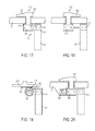
- Figures 17-22 are schematic illustrations that depict alternatively configured switch mechanisms for translating an axially movable member, such as the collar of the transmission assembly;
- FIG. 23 is a schematic illustration of another transmission assembly constructed in accordance with the teachings of the present disclosure.
- Figure 24 is a plot illustrating the rotational speed of the output of the hybrid impact tool of Figure 1 as a function its output torque operating at two different speed settings and using two different motor control schemes;
- FIG. 25 is a perspective, partly broken away view of another hybrid impact tool constructed in accordance with the teachings of the present disclosure.
- Figure 26 is a top plan, partly broken away view of the hybrid impact tool of Figure 25 as set in drill mode that operates a reduction gearset at a first speed ratio;
- Figure 27 is a top plan, partly broken away view of the hybrid impact tool of Figure 25 as set in an impact mode that operates a reduction gearset at a second speed ratio.
- a hybrid impact tool constructed in accordance with the teachings of the present disclosure is generally indicated by reference numeral 8.
- the hybrid impact tool 8 may be either a corded or cordless (i.e., battery powered) device and that the teachings of the present disclosure may have applicability to other types of power tools, including without limitation screwdrivers, drill/drivers, hammer-drill/drivers, rotary hammers and impact drivers.
- the hybrid impact tool can include a housing 10, a motor assembly 12, a multi-speed transmission assembly 14, an impact mechanism 16, an output spindle 18, a mode change mechanism 20, a chuck 22, a trigger assembly 24 and a battery pack 26.
- the chuck 22, the trigger assembly 24 and the battery pack 26 can be conventional in their construction and operation and as such, will not be discussed in significant detail herein.
- the impact mechanism 16, output spindle 18 and mode change mechanism 20 can be constructed as described in co-pending U.S. Provisional Patent Application No. 61/100,091 entitled “Hybrid Impact Tool", the entire disclosure of which is hereby incorporated by reference as if set forth herein in its entirety.
- the housing 10 can include a pair of mating housing shells 30 and a gear case 32 that can be removably coupled to the housing shells 30.
- the housing shells 30 can cooperate to define a handle portion 36 and a body portion 38.
- the handle portion 36 can include a battery pack mount 40, to which the battery pack 26 may be removably mounted, and a switch mount 42 ( Fig. 3 ).
- the trigger assembly 24 can include a trigger 50 for operating the hybrid impact tool 8 and a trigger controller 52 ( Fig. 3 ), which can include a switch 54 ( Fig. 3 ) that can be employed to electrically couple the motor assembly 12 to a power source, such as the battery pack 26, to operate the hybrid impact tool 8.
- the body portion 38 can define a motor cavity 58, which can be configured to receive the motor assembly 12, a rear bearing mount 60 and a front bearing mount 62.
- the gear case 32 can be a container-shaped structure that can be fixedly but removably coupled to the housing shells 30 to house the multi-speed transmission assembly 14, the impact mechanism 16, the output spindle 18 and the mode change mechanism 20.
- the motor assembly 12 can include a motor 70 that can include an output shaft 72 having a rear end 74 and a forward end 76.
- the rear end 74 can be supported for rotation relative to the housing by a bearing 78 that can be received in the rear mount 60.
- the motor 70 can be electrically coupled to the trigger assembly 24 and the battery pack 26 ( Fig. 1 ) in a conventional manner. It will be appreciated that while the present disclosure describes the motor assembly 12 as including an electrically-powered motor, those of skill in the art will appreciate that the motor 70 can be any type of motor (e.g., pneumatic, hydraulic, AC electric) for providing rotary power to the multi-speed transmission assembly 14.
- the multi-speed transmission assembly 14 can include a reduction gearset 100 and a speed selector 102.
- the reduction gearset 100 can be a single stage, two-speed gearset but those of skill in the art will appreciate that the reduction gearset 100 could be constructed with more stages depending on a desired gear reduction ratio.
- the reduction gearset 100 can include an input sun gear 110, a first set of input planet gears 112, a second set of input planet gears 114, an input carrier 116, a first input ring gear 118 and a second input ring gear 120.
- the input sun gear 110 can be coupled for rotation with the output shaft 72 of the motor 70.
- the first set of input planet gears 112 can comprise a plurality of first planet gears having a first quantity of teeth that can be arranged about a first pitch diameter
- the second set of input planet gears 114 can comprise a plurality of second planet gears having a second quantity of teeth that can be arranged about a second pitch diameter.
- the first input ring gear 118 can be an annular structure having a plurality of internal teeth 126 disposed proximate a forward axial face and a plurality of external splines or teeth 128 that can extend radially outwardly from a portion of the first input ring gear 118 proximate a rear axial face.
- the plurality of internal teeth 126 can be meshingly engaged with the teeth of the first planet gears of the first set of planet gears 112.
- the second input ring gear 120 can include a plurality of internal teeth 130, which can be meshingly engaged with the teeth of the second planet gears of the second set of planet gears 114, and a plurality of external splines or teeth 132 ( Fig.
- the input carrier 116 can include a rear carrier plate 140, a front carrier plate 142 and a plurality of pins (not specifically shown) that can be fixedly coupled to the rear and front carrier plates 140 and 142.
- the planet gears of the first and second sets of input planet gears 112 and 114 can be rotatably mounted on respective pins.
- An input spindle 150 of the impact mechanism 16 can be coupled for rotation with the front carrier plate 142.
- the rear carrier plate 140 can be an annular structure that can be received over the output shaft 72 of the motor 70.
- the rear carrier plate 140 can include a first portion 160 and a second portion 162.
- the first portion 160 can be abutted against a rear surface of the planet gears of the first set of planet gears 112 to inhibit undesired axial movement of the first and second sets of planet gears 112 and 114.
- the second portion 162 can be relatively smaller in diameter than the first portion 160 and can be configured to receive therein a front motor bearing 166 that can support the output shaft 72.
- An impact mechanism support bearing 168 can be received over the second portion 162 of the rear carrier plate 140 and can be engaged to a bearing support plate 170 that is received in the housing 10 and disposed between the motor 70 and the reduction gearset 100. Configuration in this manner nests the front motor bearing 166 and the impact mechanism support bearing 168 to reduce the overall length of the tool, as well as aids in the alignment of the motor 70 and the impact mechanism 16 ( Fig. 3 ) as the front motor bearing 166 and the impact mechanism support bearing 168 are mounted on the same machined piece (i.e., the rear carrier plate 140).
- the planet gears of the first set of planet gears 112 are axially offset from the motor 70 by a distance that is smaller than the amount by which the planet gears of the second set of planet gears 114 are axially offset from the motor 70 (i.e., the planet gears of the first set of planet gears 112 are closer to the motor 70 than the planet gears of the second set of planet gears 114); the second quantity of teeth is greater than the first quantity of teeth; the second pitch diameter is larger than the first pitch diameter; each of the planet gears of the first set of planet gears 112 is coupled for rotation with a corresponding one of the planet gears of the second set of planet gears 114 (e.g., the planet gears of the first and second sets of planet gears 112 and 114 can be integrally formed); and only the planet gears of the second set of input planet gears 114 are meshingly engaged with the input sun gear 110 ( Fig.
- the speed selector 102 can include a switch assembly 200 and an actuator assembly 202.
- the switch assembly 200 can include a switch 210 and a pair of first detent members (not specifically shown), while the actuator assembly 202 can include a rail 220, a collar 222, a first biasing spring 224 and a second biasing spring 226.
- the switch 210 can include a plate structure 230, a switch member 232, a pair of second detent members (not specifically shown) and a bushing 236.
- the plate structure 230 can be received in a pair of slots (not specifically shown) formed into the housing shells 30 ( Fig. 1 ) generally parallel to the longitudinal axis 240 of the reduction gearset 100.
- the switch member 232 can be configured to receive a manual input from an operator of the hybrid impact tool 8 ( Fig. 1 ) to move the switch 210 between a first switch position and a second switch position.
- Indicia may be marked or formed on one or both of the housing shells 30 ( Fig. 1 ) or the plate structure 230 to indicate a position into which the switch 210 is located.
- the second detent members can cooperate with the first detent members to resist movement of the switch 210.
- the second detent members comprise a plurality of detent recesses that are formed in the plate structure 230.
- the bushing 236 can be coupled to a lateral side of the plate structure 230 and can include a bushing aperture (not specifically shown) and first and second end faces 244 and 246, respectively.
- Each of the housing shells 30 can define a pair of detent mounts (not specifically shown) that can be configured to hold the first detent members.
- the first detent members can be leaf springs that can be configured to engage the detent recesses that are formed in the plate structure 230 to resist movement of the switch 210 relative to the housing shells 30 ( Fig. 1 ).
- the rail 220 can include a generally cylindrical rail body 250 and a head portion 252 that can be relatively large in diameter than the rail body 250.
- the rail 220 can be received through the bushing aperture in the bushing 236 such that the bushing 236 is slidably mounted on the rail body 250.
- the collar 222 can be an annular structure that can include a mount 260, a plurality of internal splines or teeth 262 formed about the inside surface of the collar 222, and a plurality of teeth 264 formed into the front axial face of the collar 222.
- An end of the rail body 250 opposite the head portion 252 can be received into the mount 260 to fixedly couple the rail 220 to the collar 222.
- the rail body 220 is press-fit into the mount 260, but it will be appreciated that other coupling techniques, including bonding, adhesives, pins and threaded fasteners, could be employed to couple the rail 220 to the collar 222.
- the internal splines or teeth 262 formed about the inside surface of the collar 222 can be sized to engage the external splines or teeth 128 formed on the first input ring gear 118, while the plurality of or teeth 264 formed into the front axial face of the collar 222 can be sized to engage the external splines or teeth 132 that extend rearwardly from the rear axial face 134 of the body 136 of the second input ring gear 120.
- Lugs 270 formed on the collar 222 can be slidably received in axially extending grooves (not specifically shown) formed in the gear case 32 ( Fig. 1 ) to aid in guiding the collar 222.
- the first biasing spring 224 can be mounted on the rail body 250 between the head portion 252 and the first end face 244 of the bushing 236.
- the second biasing spring 226 can be mounted on the rail body 250 between the second end face 246 of the bushing 236 and the collar 222.
- the collar 222, the first input ring gear 118 and the second input ring gear 120 are shown relative to the longitudinal axis 240 of the reduction gearset 100. It will be appreciated that the collar 222 can be moved axially along the longitudinal axis 240 between a first position ( Fig. 7 ) and a second position ( Fig. 8 ).
- the internal splines or teeth 262 (best shown in Fig. 3 ) formed about the inside surface of the collar 222 can be meshingly engaged with the external splines or teeth 128 (best shown in Fig. 3 ) of the first input ring gear 118 while the internal splines or teeth 264 formed on the collar 222 are disengaged from the external splines or teeth 132 formed on the second input ring gear 120. Positioning of the collar 222 in this manner permits the reduction gearset 100 to operate at a first gear ratio.
- rotary power received from the motor 70 is transmitted through the input sun gear 110 to cause the planet gears of the second set of input planet gears 114 to rotate about the pins of the input carrier 116.
- the planet gears of the first set of input planet gears 112 are coupled for rotation with the planet gears of the second set of input planet gears 114, the planet gears of the first set of input planet gears 112 will rotate about the pins of the input carrier 116. Since the first input ring gear 118 is non-rotatably coupled to the gear case 32 ( Fig.
- rotation of the planet gears of the first set of input planet gears 112 causes rotation of the input carrier 116 at a speed that is determined in part based on the first gear ratio. It will be appreciated that as the collar 222 is not engaged to the second input ring gear 120, rotation of the planet gears of the second set of input planet gears 114 will cause rotation of the second input ring gear 120.
- the internal splines or teeth 262 (best shown in Fig. 3 ) formed about the inside surface of the collar 222 can be disengaged from the external splines or teeth 128 (best shown in Fig. 3 ) of the first input ring gear 118 while the internal splines or teeth 264 formed on the collar 222 can be engaged to the external splines or teeth 132 (best shown in Figure 5 .) formed on the second input ring gear 120. Positioning of the collar 222 in this manner permits the reduction gearset 100 to operate at a second gear ratio.
- rotary power received from the motor 70 is transmitted through the input sun gear 110 to cause the planet gears of the second set of input planet gears 114 to rotate about the pins of the input carrier 116. Since the second input ring gear 120 is non-rotatably coupled to the gear case 32 ( Fig. 4 ) via the collar 222, rotation of the planet gears of the second set of input planet gears 114 causes rotation of the input carrier 116 at a speed that is determined in part based on the second gear ratio.
- Configuration of the reduction gearset 100 and collar 222 in the manner provides several advantages.
- the above-described configuration permits the collar 222 to be shifted into a neutral position when being moved between the first and second positions (i.e., the collar 222 will fully disengage the first input ring gear 118 before initiating engagement with the second input ring gear 120 and vice versa) as is shown in Figure 9 .
- the combination of the axial spacing apart of the internal splines or teeth 126 and the external splines or teeth 128 of the first input ring gear 118 provides additional room for shifting the collar 222 while efficiently packaging the front motor bearing 166 and the impact mechanism support bearing 168 in a way that provides the desired neutral position in addition to a reduction in the overall length of the hybrid impact tool 8 ( Fig. 1 ).
- the "additional" length needed to provide a neutral position is obtained by positioning the external splines or teeth 128 of the first input ring gear 118 further rearwardly than they otherwise would have been, so that the external splines or teeth 128 are located in a position or axial zone that is employed to house the bearings 166 and 168 that support the motor 70 and the impact mechanism 16 permits the overall length of the hybrid impact tool 8 ( Fig. 1 ) to be reduced.
- the above-described configuration utilizes splines or teeth on the rear and front faces of the second input ring gear 120 and the collar 222, respectively, to reduce the overall diameter of the reduction gearset 100 as compared with an arrangement that places the mating splines or teeth on the second input ring gear 120 and the collar 222 in a radial orientation (as with the first input ring gear 118 and the collar 222).
- the first input ring gear 118 can be relatively smaller in diameter than the second input ring gear 120 and consequently, the use of mating splines or teeth disposed in a radial direction do not have a similar impact on the overall diameter of the reduction gearset 100.
- first and second biasing springs 224 and 226 are configured to resiliently couple the collar 222 to the switch 210 in a manner that provides for a modicum of compliance.
- the switch 210 can be translated into the second switch position without fully moving the collar 222 by an accompanying amount.
- the second biasing spring 226 is compressed between the second end face 246 of the bushing 236 and the mount 260 of the collar 222.
- Rotation of the second input ring gear 120 relative to the collar 222 can permit the external splines or teeth 132 formed on the second input ring gear 120 to align to the internal splines or teeth 264 formed on the collar 222 and once aligned, the second biasing spring 226 can urge the collar 222 forwardly into engagement with the second input ring gear 120.
- the switch 210 can be translated into the first switch position without fully moving the collar 222 by an accompanying amount.
- the first biasing spring 224 is compressed between the head portion 252 of the rail 220 and the first end face 244 of the bushing 236.
- Rotation of the first input ring gear 118 relative to the collar 222 can permit the external splines or teeth 128 to align to the internal splines or teeth 262 formed about the collar 222 and once aligned, the first biasing spring 224 can urge the collar 222 rearwardly into engagement with the first input ring gear 118.
- the motor bearing 166 may be positioned somewhat differently from that which is described above as is shown in Figures 10, 11 and 12 .
- the reduction gearset 100' includes a fixed input stage 300 and a fixed output stage 302 (i.e., the input and output stages 300 and 302 always provide corresponding gear reductions).
- the motor output shaft 72' is received through an input carrier 304 associated with the input stage 300 and the motor bearing 166' is received in an output carrier/spindle 308 associated with the output stage 302.
- the impact mechanism bearing 168' is mounted on the output carrier 308.
- FIG. 11 partly illustrates a similar motor output shaft 72'" except that the portion 312 of the motor output shaft 72" between the input sun gear 110 " and the motor bearing 166" is necked down in diameter.
- the example of Figure 12 is similar to the previous example except that the motor output shaft 72"' is received into an end of the input sun gear 110"' and the motor bearing 166"' is received onto an opposite end of the input sun gear 110"'.
- the reduction gearset 100 can be configured such that the quotient of the quantity of teeth 400 on the planet gears 402 of the second set of input planet gears 114 divided by the quantity of teeth 406 on the planet gears 408 of the first set of input planet gears 112 is an integer.
- configuration of the first and second sets of planet gears 112 and 114 in this manner eliminates the need to time the planet gears 402, 408 relative to another gear in the reduction gearset 100.
- a timing aperture 420 is formed in the planet gear 402' at a desired location.
- the desired location is in-line with teeth 400a' and 406a' so that a line extending from the center of the gear 402' can bisect the teeth 402a', 406a' and the timing aperture 420.
- a fixture 450 is configured with a plurality of pins 452 for aligning the gears 402', 408' relative to the remainder of the gearset.
- the gears 402' and 408' are initially assembled to the planet carrier 116 ( Fig. 3 ) and the pins 452 of the fixture 450 are inserted into the timing apertures 420 in the gears 402'.
- the first input ring gear 118 is meshed with the gears 408' and the fixture 450 can be removed.
- the second input ring gear 120 can be meshed with the planet gears 402'.
- speed selector 102 ( Fig. 6 ) has been illustrated and described as including an actuator assembly 202 ( Fig. 6 ) with a rail 220 ( Fig. 6 ), a first biasing spring 224 ( Fig. 6 ) and a second biasing spring 226 ( Fig. 6 ), it will be appreciated that the speed selector may be configured somewhat differently.
- the speed selector 102' of Figures 17 and 18 includes a switch assembly 200' and an actuator assembly 202'.
- the switch assembly 200' can include a rotary knob 500 that can extend through the housing 10', whereas the actuator assembly 202' can include a first portion 510, which can be coupled for rotation with the rotary knob 500, and a second portion 512 that can be fixedly coupled to the collar 222'.
- the first portion 510 can include a first magnet 514 having a north pole N and a south pole S
- the second portion 512 can include a second magnet 516 having a north pole N and a south pole S.
- the collar 222' is non-rotatably but axially slidably coupled to another structure, such as a pair of rods (not shown) that can be fixedly coupled to the housing 10'.
- Rotation of the rotary knob 500 into a first rotary position can orient a pole of the first magnet 514 to an opposite pole on the second magnet 516 (e.g., south pole S to north pole N, respectively) so as to cause the second magnet 516 (and the collar 222' with it) to be drawn toward the first portion to thereby shift the collar 222' into the first position.
- rotation of the rotary knob 500 into a second rotary position Fig.
- a slug 520 formed of a magnetically susceptible material, such as steel, can be coupled to the housing 10" to aid in maintaining the rotary knob 500 in the first and second rotary positions due to magnetic attraction between the slug 520 and the first magnet 514. So in comparison to the speed selector 102, and similar selectors known in the art, this design provides, an actuating force, shift compliance and dententing without the use of springs, cams or slots.
- FIG. 19 employs a slidable switch 210' having a rack 530 formed thereon, and an actuator assembly 202" having a pinion 532 that meshingly engages the rack 530 and into which the first magnet 514 is disposed. Sliding of the slidable switch 210' can orient the north and south poles N and S of the first magnet 514 to attract or repel the second magnet 516 as desired.
- Figure 21 is similar to that of Figures 17 and 18 , except that the rotary knob 500' is disposed between two axially movable collars 222a and 222b into each of which is disposed one of the second magnets 516.
- multiple magnets 514a, 514b, 514c, 514d are employed, but it will be appreciated that the quantity and orientation of the first magnets 514 and the orientation of the second magnets 516 can be configured to provide a desired movement scheme.
- the example of Figure 22 is similar to the example of Figure 19 except that a pair of racks 530' are formed on the sides of the slidable switch 210", a pair of pinions 532' are engaged to the racks 530' and the first magnets 514 are disposed vertically below the pinions 532'.
- the transmission 600 include a sun gear 602, a plurality of first planet gears 604, which are meshingly engaged to the sun gear 602, a plurality of second planet gears 606, which are fixed for rotation with corresponding ones of the first planet gears 604, a first ring gear 608, which is meshingly engaged with the first planet gears 604, a second ring gear 610, which is meshingly engaged with the second planet gears 606, a planet carrier 612, which has pins 614 onto which the first and second planet gears 604 and 606 are rotatably received, a shifting collar 616 and an output spindle 618.
- the shifting collar 616 has a plurality of internal teeth 620 and a plurality of external teeth 622.
- the second ring gear 610 can include a radially inwardly extending wall 630 and a plurality of teeth 632 that can be coupled to the wall 630.
- the planet carrier 612 can include a plurality of teeth 640.
- the shifting collar 616 can be splined to the output spindle 618 to permit the shifting collar 616 to be coupled for rotation with the output spindle 618 but permit the shifting collar 616 to be moved axially relative to the output spindle 618.
- the transmission 600 may be operated in a first speed ratio in which a collar 650 couples the first ring gear 608 to a structure, such as a housing 652, to inhibit rotation of the first ring gear 608 relative to the housing 652.
- the shifting collar 616 can be moved into a position in which the teeth 622 of the shifting collar 616 are engaged to the teeth 632 of the second ring gear 610.
- the sun gear 602, first planet gears 604 and first ring gear 608 cooperate to cause the second planet gears 606 to rotate at a first rate, which drives the second ring gear 610 and in turn, drives the shifting collar 616 to cause the transmission 600 to operate in a low speed ratio.
- the transmission 600 may be operated in a second speed ratio in which the collar 650 couples the second ring gear 610 to the housing 652 to inhibit rotation of the second ring gear 610 relative to the housing 652.
- the shifting collar 616 can be moved into a position in which the teeth 620 of the shifting collar 616 are engaged to the teeth 640 of the planet carrier 612, while the teeth 622 are disengaged from the teeth 632.
- the sun gear 602, first planet gears 604, second planet gears 606 and second ring gear 610 cooperate to cause the planet carrier 612 to rotate at a second rate, which drives the shifting collar 616 to cause the transmission 600 to operate in a high speed ratio.
- the trigger controller 52 Fig. 3
- the hybrid impact tool 8 Fig. 1
- each of the schemes can be employed to select a duty cycle of the electrical power that is provided to the motor 70 ( Fig. 3 ) via a pulse-width modulation technique.
- a first duty cycle having a relatively large ratio of on-time relative to the total time of the duty cycle can be employed to rotate the output of the hybrid impact tool 8 ( Fig. 1 ) at a relatively high speed
- a second duty cycle having a relatively smaller ratio of on-time relative to the total time of the duty cycle can be employed to rotate the output of the hybrid impact tool 8 ( Fig. 1 ) at a relatively lower speed.
- Combining electronic speed control with the multi-speed capabilities of the reduction gearset 100 ( Fig. 3 ) can provide the hybrid impact tool 8 ( Fig. 1 ) with four (or more) distinct rotational speeds that may be selected as desired to complete various tasks.
- a brushless DC motor such as an IMP type brushless DC motor, may be employed for the motor 70 ( Fig. 3 ) to provide enhanced motor control.
- the speed selector 102-1 includes a plate structure 230-1 that is coupled to the shift cam 5010-1 of the mode change mechanism 20-1.
- the plate structure 230-1 can define a pair of bushings 236-1 and 236-2, which can be slidably mounted on a rail 220-1 and a biasing spring 224-1 can be received between the bushings 236-1 and 236-2 and fixed to the rail 220-1 at a predetermined location (such as at a mid-point of the stroke of the plate structure 230-1).
- Pivoting movement of the shift cam 5010-1 is employed to cause corresponding movement of a shaft 5002-1 to move a shift fork 5000-1 and a mode collar 604-1 as is described in the above-referenced Provisional Patent Application.
- the shift fork 5000-1 can be moved between a first position to engage mode collar 604-1 to both the input spindle 550-1 ( Fig. 27 ) of the impact mechanism 16-1 and the hammer 36-1 of the impact mechanism 16-1, and a second position to disengage the mode collar 604-1 from the hammer 36-1 of the impact mechanism 16-1.
- a spring 224-2 can bias the shift fork 5000-1 toward a desired position.
- Pivoting movement of the shift cam 5010-1 also causes corresponding sliding motion of the plate structure 230-1 on the rail 220-1 to compress the biasing spring 224-1 against one of the bushings 236-1 and 236-2 depending on the direction in which the shift cam 5010-1 is moved.
- the rail 220-1 is fixedly coupled to the collar 222
- pivoting movement of the shift cam 5010-1 will effect a change in the gear ratio of the reduction gearset 100.
- the biasing spring 224-1 permits the plate structure 230-1 to be moved without a corresponding movement of the collar 222 in situations where the collar 222 is not aligned to either the first ring gear 118 or the second ring gear 120.
Landscapes
- Engineering & Computer Science (AREA)
- Mechanical Engineering (AREA)
- Structure Of Transmissions (AREA)
- Retarders (AREA)
- Drilling And Boring (AREA)
- Portable Power Tools In General (AREA)
Applications Claiming Priority (3)
| Application Number | Priority Date | Filing Date | Title |
|---|---|---|---|
| US28978009P | 2009-12-23 | 2009-12-23 | |
| US29075909P | 2009-12-29 | 2009-12-29 | |
| US12/971,940 US8460153B2 (en) | 2009-12-23 | 2010-12-17 | Hybrid impact tool with two-speed transmission |
Publications (3)
| Publication Number | Publication Date |
|---|---|
| EP2338647A2 true EP2338647A2 (fr) | 2011-06-29 |
| EP2338647A3 EP2338647A3 (fr) | 2013-03-13 |
| EP2338647B1 EP2338647B1 (fr) | 2014-11-19 |
Family
ID=43859789
Family Applications (1)
| Application Number | Title | Priority Date | Filing Date |
|---|---|---|---|
| EP10196006.0A Active EP2338647B1 (fr) | 2009-12-23 | 2010-12-20 | Outil d'impact hybride doté d'une transmission à deux vitesses |
Country Status (3)
| Country | Link |
|---|---|
| US (2) | US8460153B2 (fr) |
| EP (1) | EP2338647B1 (fr) |
| CN (1) | CN202241183U (fr) |
Cited By (6)
| Publication number | Priority date | Publication date | Assignee | Title |
|---|---|---|---|---|
| CN102765080A (zh) * | 2012-07-18 | 2012-11-07 | 宁波汉浦工具有限公司 | 双速电锤 |
| EP2564991A3 (fr) * | 2011-08-30 | 2013-09-25 | Black & Decker Inc. | Outil électrique |
| EP3147077A1 (fr) * | 2015-09-22 | 2017-03-29 | HILTI Aktiengesellschaft | Machine-outil portative |
| EP3211786A4 (fr) * | 2014-10-22 | 2018-05-02 | Changzhou Globe Co., Ltd. | Système de commande et procédé de commande à puissance constante et double vitesse reposant sur un outil électrique à courant continu sans balai |
| EP2551064A3 (fr) * | 2011-07-29 | 2018-07-25 | Black & Decker Inc. | Outil électrique multivitesse |
| US12011814B2 (en) | 2011-07-29 | 2024-06-18 | Black & Decker Inc. | Multispeed power tool |
Families Citing this family (32)
| Publication number | Priority date | Publication date | Assignee | Title |
|---|---|---|---|---|
| US8887831B2 (en) * | 2011-11-17 | 2014-11-18 | Black & Decker Inc. | Transmission for power tool with variable speed ratio |
| US9457462B2 (en) * | 2012-05-02 | 2016-10-04 | Milwaukee Electric Tool Corporation | Power tool having a speed selector switch |
| CN103867684A (zh) * | 2012-12-17 | 2014-06-18 | 博世力士乐(北京)液压有限公司 | 双速比回转减速机 |
| JP6050110B2 (ja) | 2012-12-27 | 2016-12-21 | 株式会社マキタ | インパクト工具 |
| EP2777883A1 (fr) | 2013-03-13 | 2014-09-17 | Black & Decker Inc. | Dispositif de rétention de douille |
| JP6309881B2 (ja) * | 2014-11-14 | 2018-04-11 | 株式会社マキタ | 作業工具 |
| JP6901346B2 (ja) | 2017-08-09 | 2021-07-14 | 株式会社マキタ | 電動作業機 |
| JP6916060B2 (ja) * | 2017-08-09 | 2021-08-11 | 株式会社マキタ | 電動作業機 |
| DE102017119807A1 (de) * | 2017-08-29 | 2019-02-28 | Festool Gmbh | Hand-Werkzeugmaschine |
| US11318589B2 (en) | 2018-02-19 | 2022-05-03 | Milwaukee Electric Tool Corporation | Impact tool |
| US10987784B2 (en) * | 2018-02-23 | 2021-04-27 | Ingersoll-Rand Industrial U.S., Inc. | Cordless impact tool with brushless, sensorless, motor and drive |
| US11241746B2 (en) * | 2018-04-03 | 2022-02-08 | Delbert Tesar | Transmission for shop tool based on star compound gear train |
| CN110617325B (zh) * | 2018-06-20 | 2021-06-11 | 宝时得科技(中国)有限公司 | 变速传动机构及其变速工具 |
| US11027404B2 (en) | 2018-07-19 | 2021-06-08 | Milwaukee Electric Tool Corporation | Lubricant-impregnated bushing for impact tool |
| EP3894136A4 (fr) * | 2018-12-10 | 2023-01-11 | Milwaukee Electric Tool Corporation | Outil d'impact à couple élevé |
| WO2020132587A1 (fr) * | 2018-12-21 | 2020-06-25 | Milwaukee Electric Tool Corporation | Outil à impact à couple élevé |
| JP7210291B2 (ja) | 2019-01-10 | 2023-01-23 | 株式会社マキタ | 電動ドライバドリル |
| CN216398138U (zh) | 2019-02-18 | 2022-04-29 | 米沃奇电动工具公司 | 冲击工具 |
| US11673240B2 (en) | 2019-08-06 | 2023-06-13 | Makita Corporation | Driver-drill |
| JP2021045844A (ja) * | 2019-09-13 | 2021-03-25 | 株式会社マキタ | 電動作業機 |
| JP7386027B2 (ja) * | 2019-09-27 | 2023-11-24 | 株式会社マキタ | 回転打撃工具 |
| JP7320419B2 (ja) | 2019-09-27 | 2023-08-03 | 株式会社マキタ | 回転打撃工具 |
| US11964375B2 (en) | 2019-11-27 | 2024-04-23 | Black & Dekcer Inc. | Power tool with multispeed transmission |
| US11705778B2 (en) | 2019-12-19 | 2023-07-18 | Black & Decker Inc. | Power tool with compact motor assembly |
| US11509193B2 (en) | 2019-12-19 | 2022-11-22 | Black & Decker Inc. | Power tool with compact motor assembly |
| US12059775B2 (en) | 2019-12-19 | 2024-08-13 | Black & Decker Inc. | Power tool with compact motor assembly |
| USD948978S1 (en) | 2020-03-17 | 2022-04-19 | Milwaukee Electric Tool Corporation | Rotary impact wrench |
| US11685036B2 (en) | 2020-07-27 | 2023-06-27 | Techtronic Cordless Gp | Motor mounting assembly for a power tool |
| US20220040940A1 (en) * | 2020-08-04 | 2022-02-10 | Milwaukee Electric Tool Corporation | Powered tire repair tool |
| US11865691B2 (en) | 2020-12-10 | 2024-01-09 | Black & Decker Inc. | Power tool with chuck key holder |
| US12011815B2 (en) * | 2020-12-18 | 2024-06-18 | Black & Decker Inc. | Impact power tool |
| US11872680B2 (en) * | 2021-07-16 | 2024-01-16 | Black & Decker Inc. | Impact power tool |
Citations (1)
| Publication number | Priority date | Publication date | Assignee | Title |
|---|---|---|---|---|
| US10009108B2 (en) | 2011-02-11 | 2018-06-26 | Menara Networks, Inc. | Coherent and pulse amplitude modulation in a pluggable optical transceiver |
Family Cites Families (140)
| Publication number | Priority date | Publication date | Assignee | Title |
|---|---|---|---|---|
| US3195702A (en) * | 1960-11-16 | 1965-07-20 | Rockwell Mfg Co | Apparatus for controlling tightness of fasteners |
| DE1478807A1 (de) * | 1962-07-03 | 1969-03-13 | Bosch Gmbh Robert | Motorisch angetriebenes Drehschlaggeraet |
| DE1652685C3 (de) | 1968-02-08 | 1982-03-25 | Hilti AG, 9494 Schaan | Einrichtung zum Umschalten von Schlagbohren auf Drehbohren |
| IL33084A (en) | 1968-04-04 | 1972-05-30 | Plessey Co Ltd | Force-operated tools |
| AT305922B (de) * | 1969-02-18 | 1973-03-26 | Gkn Screws Fasteners Ltd | Kraftbetätigtes Werkzeug |
| DE1941093A1 (de) | 1969-08-13 | 1971-04-01 | Licentia Gmbh | Schlagabschaltung an einem motorisch angetriebenen Handwerkzeug zum Bohren und Hammerbohren |
| BE756623A (fr) * | 1969-09-26 | 1971-03-01 | Atlas Copco Ab | Moteur rotatif a percussion |
| GB1282300A (en) * | 1969-12-08 | 1972-07-19 | Desoutter Brothers Ltd | Improved impact wrench or screwdriver |
| GB1303571A (fr) * | 1971-04-30 | 1973-01-17 | ||
| DE2557118C2 (de) | 1975-12-18 | 1984-01-12 | C. & E. Fein Gmbh & Co, 7000 Stuttgart | Tragbare Drehschlag-Maschinen mit ausrastbarem Schlagwerk |
| SU810472A1 (ru) | 1976-08-23 | 1981-03-07 | Всесоюзный Научно-Исследовательскийи Проектно-Конструкторский Институтмеханизированного И Ручногостроительно-Монтажного Инструмента,Вибраторов И Строительно-Отделочныхмашин | Ударный гайковерт |
| DE2932470A1 (de) * | 1979-08-10 | 1981-02-26 | Scintilla Ag | Motorgetriebenes handwerkzeug, insbesondere heimwerkerkombinationsmaschine |
| GB2102718B (en) | 1981-07-24 | 1985-08-14 | Black & Decker Inc | Improvements in or relating to rotary percussive drills |
| JPS62173180A (ja) | 1986-01-27 | 1987-07-30 | 松下電工株式会社 | 振動ドリル |
| JPH0747303B2 (ja) | 1986-05-15 | 1995-05-24 | 株式会社クラレ | 多層成形体 |
| JPS62297007A (ja) | 1986-06-14 | 1987-12-24 | Matsushita Electric Works Ltd | 振動ドリル |
| JPH0741551B2 (ja) | 1986-11-12 | 1995-05-10 | 株式会社芝浦製作所 | 衝撃工具 |
| US4986369A (en) * | 1988-07-11 | 1991-01-22 | Makita Electric Works, Ltd. | Torque adjusting mechanism for power driven rotary tools |
| SE469419B (sv) * | 1988-11-14 | 1993-07-05 | Atlas Copco Tools Ab | Motordrivet momentimpulsverktyg |
| JP2828640B2 (ja) | 1988-11-15 | 1998-11-25 | 松下電工株式会社 | 回転衝撃工具 |
| DE3913299A1 (de) | 1989-04-22 | 1990-10-25 | Itw Ateco Gmbh | Verfahren und vorrichtung zum formen eines gewindes in gestein oder beton |
| JP2828657B2 (ja) | 1989-04-25 | 1998-11-25 | 松下電工株式会社 | ハンマードリル |
| DE3920471C1 (fr) | 1989-06-22 | 1990-09-27 | Wagner, Paul-Heinz, 5203 Much, De | |
| JP2754047B2 (ja) | 1989-07-11 | 1998-05-20 | 株式会社芝浦製作所 | 振動ドリル |
| JP2856790B2 (ja) | 1989-11-28 | 1999-02-10 | 池田 毅 | 波動発電装置 |
| US5025903A (en) * | 1990-01-09 | 1991-06-25 | Black & Decker Inc. | Dual mode rotary power tool with adjustable output torque |
| DE4038502C2 (de) | 1990-12-03 | 1994-02-17 | Atlas Copco Elektrowerkzeuge | Handgeführte Elektrowerkzeugmaschine mit einer Einrichtung zum Einstellen des Drehmoments |
| DE4132023A1 (de) * | 1991-09-26 | 1993-04-01 | Bosch Gmbh Robert | Einrichtung an handwerkzeugmaschinen |
| US5269733A (en) * | 1992-05-18 | 1993-12-14 | Snap-On Tools Corporation | Power tool plastic gear train |
| JPH0610844A (ja) | 1992-06-24 | 1994-01-21 | Seiko Epson Corp | 吐出検出装置 |
| DE4328599C2 (de) | 1992-08-25 | 1998-01-29 | Makita Corp | Rotations-Schlagwerkzeug |
| JPH06182674A (ja) | 1992-12-16 | 1994-07-05 | Makita Corp | 回転衝撃工具 |
| JP3532504B2 (ja) | 1992-12-16 | 2004-05-31 | 株式会社マキタ | 回転衝撃工具 |
| JP3049678B2 (ja) | 1993-01-18 | 2000-06-05 | キヤノン株式会社 | 光学系配置装置 |
| JPH06210507A (ja) | 1993-01-18 | 1994-08-02 | Makita Corp | 回転工具における動力切換機構 |
| DE4301610C2 (de) | 1993-01-22 | 1996-08-14 | Bosch Gmbh Robert | Schlagschrauber |
| GB9304540D0 (en) * | 1993-03-05 | 1993-04-21 | Black & Decker Inc | Power tool and mechanism |
| JP3372345B2 (ja) | 1993-05-26 | 2003-02-04 | 松下電工株式会社 | インパクト回転工具 |
| JPH0780711A (ja) | 1993-09-16 | 1995-03-28 | Makita Corp | 打撃力可変型震動ドリル |
| US5447205A (en) * | 1993-12-27 | 1995-09-05 | Ryobi Motor Products | Drill adjustment mechanism for a hammer drill |
| DE4344849A1 (de) * | 1993-12-29 | 1995-07-06 | Fein C & E | Werkzeugmaschine |
| US5457860A (en) * | 1994-01-24 | 1995-10-17 | Miranda; Richard A. | Releasable clasp |
| AU1205695A (en) | 1994-02-04 | 1995-08-21 | Dumitru Panu Misailescu | Portable hand-held machine |
| DE9404069U1 (de) | 1994-03-10 | 1994-06-30 | Fan Chang, We Chuan, Taichung | Schlagdrehwerkzeug |
| DE9406626U1 (de) | 1994-04-20 | 1994-06-30 | Chung, Lee-Hsin-Chih, Chung-Li, Taoyuan | Elektrische Handbohrmaschine mit Doppelfunktion |
| JPH07328955A (ja) | 1994-06-09 | 1995-12-19 | Hitachi Koki Co Ltd | ハンマドリル |
| JP3284759B2 (ja) * | 1994-06-09 | 2002-05-20 | 日立工機株式会社 | インパクトドライバ |
| JP3685818B2 (ja) * | 1994-07-26 | 2005-08-24 | 株式会社日立メディコ | 三次元画像構成方法及びその装置 |
| SE503889C2 (sv) * | 1994-10-31 | 1996-09-23 | Atlas Copco Tools Ab | Reverserbar mutterdragare |
| DE19510578A1 (de) * | 1995-03-23 | 1996-09-26 | Atlas Copco Elektrowerkzeuge | Handwerkzeugmaschine, insbesondere Schlagschrauber |
| JP3424880B2 (ja) * | 1995-08-18 | 2003-07-07 | 株式会社マキタ | ハンマードリル |
| JP3574240B2 (ja) | 1995-11-13 | 2004-10-06 | 株式会社マキタ | ハンマードリル |
| JPH09239675A (ja) | 1996-03-08 | 1997-09-16 | Hitachi Koki Co Ltd | ハンマドリルの動作モード切換装置 |
| DE19620551C2 (de) | 1996-05-22 | 1998-04-09 | Atlas Copco Elektrowerkzeuge | Schlagbohrmaschine |
| US5711380A (en) * | 1996-08-01 | 1998-01-27 | Chen; Yueh | Rotate percussion hammer/drill shift device |
| US5836403A (en) * | 1996-10-31 | 1998-11-17 | Snap-On Technologies, Inc. | Reversible high impact mechanism |
| JP3582760B2 (ja) | 1997-04-18 | 2004-10-27 | 日立工機株式会社 | ハンマドリル |
| DE19738094C1 (de) | 1997-09-01 | 1999-03-04 | Bosch Gmbh Robert | Schlagschrauber |
| DE19809131B4 (de) | 1998-03-04 | 2006-04-20 | Scintilla Ag | Elektrohandwerkzeugmaschine |
| DE19833650A1 (de) * | 1998-07-25 | 2000-01-27 | Hilti Ag | Handbohrgerät |
| DE19833943C2 (de) * | 1998-07-28 | 2000-07-13 | Rodcraft Pneumatic Tools Gmbh | Schlagschrauber |
| JP3609626B2 (ja) * | 1998-09-16 | 2005-01-12 | 株式会社マキタ | ハンマードリル |
| JP3655481B2 (ja) | 1999-02-15 | 2005-06-02 | 株式会社マキタ | 震動ドライバドリル |
| US6142242A (en) * | 1999-02-15 | 2000-11-07 | Makita Corporation | Percussion driver drill, and a changeover mechanism for changing over a plurality of operating modes of an apparatus |
| JP3791229B2 (ja) | 1999-02-23 | 2006-06-28 | 松下電工株式会社 | インパクト回転工具 |
| US6535636B1 (en) * | 1999-03-23 | 2003-03-18 | Eastman Kodak Company | Method for automatically detecting digital images that are undesirable for placing in albums |
| US6536536B1 (en) * | 1999-04-29 | 2003-03-25 | Stephen F. Gass | Power tools |
| JP3911905B2 (ja) * | 1999-04-30 | 2007-05-09 | 松下電工株式会社 | インパクト回転工具 |
| US6223833B1 (en) * | 1999-06-03 | 2001-05-01 | One World Technologies, Inc. | Spindle lock and chipping mechanism for hammer drill |
| JP2001088051A (ja) | 1999-09-17 | 2001-04-03 | Hitachi Koki Co Ltd | 回転衝撃工具 |
| JP2001088052A (ja) | 1999-09-24 | 2001-04-03 | Makita Corp | インパクト機構付回転工具 |
| JP3683754B2 (ja) | 1999-10-05 | 2005-08-17 | 株式会社マキタ | ハンマードリル |
| DE19954931B4 (de) | 1999-11-16 | 2007-08-16 | Metabowerke Gmbh | Schalteinrichtung an einem von Hand führbaren, auf ein pulsierendes Drehmoment umschaltbaren Elektrowerkzeug |
| DE10033100A1 (de) | 2000-07-07 | 2002-01-17 | Hilti Ag | Kombiniertes Elektrohandwerkzeuggerät |
| JP2002178206A (ja) | 2000-12-12 | 2002-06-25 | Makita Corp | 振動ドリル |
| US6733414B2 (en) * | 2001-01-12 | 2004-05-11 | Milwaukee Electric Tool Corporation | Gear assembly for a power tool |
| US7101300B2 (en) * | 2001-01-23 | 2006-09-05 | Black & Decker Inc. | Multispeed power tool transmission |
| US6805207B2 (en) * | 2001-01-23 | 2004-10-19 | Black & Decker Inc. | Housing with functional overmold |
| US6676557B2 (en) * | 2001-01-23 | 2004-01-13 | Black & Decker Inc. | First stage clutch |
| JP3968994B2 (ja) | 2001-01-26 | 2007-08-29 | 松下電工株式会社 | インパクト回転工具 |
| JP2002254336A (ja) * | 2001-03-02 | 2002-09-10 | Hitachi Koki Co Ltd | 電動工具 |
| US6457635B1 (en) * | 2001-03-06 | 2002-10-01 | Tumi, Inc. | Shirt wrapper |
| JP2002273666A (ja) | 2001-03-19 | 2002-09-25 | Makita Corp | 回転打撃工具 |
| US7032683B2 (en) * | 2001-09-17 | 2006-04-25 | Milwaukee Electric Tool Corporation | Rotary hammer |
| ATE299420T1 (de) * | 2001-10-26 | 2005-07-15 | Black & Decker Inc | Werkzeughalter |
| USD462594S1 (en) * | 2001-11-27 | 2002-09-10 | Black & Decker Inc. | Cordless impact wrench |
| JP3695392B2 (ja) | 2001-12-21 | 2005-09-14 | 日立工機株式会社 | ハンマドリル |
| JP2003220569A (ja) | 2002-01-28 | 2003-08-05 | Matsushita Electric Works Ltd | インパクト回転工具 |
| DE10303235B4 (de) * | 2002-01-29 | 2011-03-31 | Makita Corp., Anjo | Drehmomentübertragungsmechanismen und Motorwerkzeuge mit solchen Drehmomentübertragungsmechanismen |
| DE10205030A1 (de) * | 2002-02-07 | 2003-08-21 | Hilti Ag | Betriebsmodi-Schalteinheit einer Handwerkzeugmaschine |
| DE20209356U1 (de) | 2002-06-15 | 2002-10-02 | Schelb, Bernhard, Dr.-Ing., 44809 Bochum | Getriebe für Elektrowerkzeuge |
| ATE299783T1 (de) * | 2002-08-27 | 2005-08-15 | Matsushita Electric Works Ltd | Elektrisch betriebener vibrationsbohrer/antrieb |
| JP4269628B2 (ja) | 2002-10-11 | 2009-05-27 | 日立工機株式会社 | ハンマドリル |
| GB2394516A (en) * | 2002-10-23 | 2004-04-28 | Black & Decker Inc | Power tool |
| TW556637U (en) * | 2003-02-24 | 2003-10-01 | Mobiletron Electronics Co Ltd | Power tool |
| DE20304314U1 (de) | 2003-03-17 | 2003-07-17 | Scheib, Bernhard, 44809 Bochum | Schaltgetriebe für Elektrowerkzeuge mit drei oder vier Gängen |
| DE20305853U1 (de) | 2003-04-11 | 2003-09-04 | Mobiletron Electronics Co., Ltd., Taya, Taichung | Elektrowerkzeug mit einem Funktionssteuerungsmechanismus zur Steuerung der Bedienung in einem Dreh- oder einem Hammermodus |
| EP1468789A3 (fr) * | 2003-04-17 | 2008-06-04 | BLACK & DECKER INC. | Embrayage pour outil électrique rotatif et outil électrique rotatif incorporant un tel embrayage |
| US6796921B1 (en) * | 2003-05-30 | 2004-09-28 | One World Technologies Limited | Three speed rotary power tool |
| US6938526B2 (en) * | 2003-07-30 | 2005-09-06 | Black & Decker Inc. | Impact wrench having an improved anvil to square driver transition |
| US7036406B2 (en) * | 2003-07-30 | 2006-05-02 | Black & Decker Inc. | Impact wrench having an improved anvil to square driver transition |
| JP4000595B2 (ja) | 2003-08-06 | 2007-10-31 | 日立工機株式会社 | 振動ドリル |
| ATE433904T1 (de) * | 2003-08-09 | 2009-07-15 | Perkins Engines Co Ltd | Zweigang planetennachschaltgetriebe |
| DE10337260A1 (de) | 2003-08-18 | 2005-03-10 | Bosch Gmbh Robert | Bedienungsmodul für eine Elektrowerkzeugmaschine |
| JP2005066785A (ja) * | 2003-08-26 | 2005-03-17 | Matsushita Electric Works Ltd | 電動工具 |
| JP4227028B2 (ja) * | 2004-01-09 | 2009-02-18 | 株式会社マキタ | ドライバドリル |
| JP4291173B2 (ja) * | 2004-02-10 | 2009-07-08 | 株式会社マキタ | インパクトドライバ |
| JP4061595B2 (ja) * | 2004-03-05 | 2008-03-19 | 日立工機株式会社 | 振動ドリル |
| JP2005246831A (ja) * | 2004-03-05 | 2005-09-15 | Hitachi Koki Co Ltd | 振動ドリル |
| JP4405900B2 (ja) * | 2004-03-10 | 2010-01-27 | 株式会社マキタ | インパクトドライバ |
| DE102004012433A1 (de) * | 2004-03-13 | 2005-09-29 | Robert Bosch Gmbh | Handwerkzeugmaschine |
| DE102004018084B3 (de) * | 2004-04-08 | 2005-11-17 | Hilti Ag | Hammerbohrgerät |
| JP4211676B2 (ja) * | 2004-05-12 | 2009-01-21 | パナソニック電工株式会社 | インパクト回転工具 |
| JP4211675B2 (ja) * | 2004-05-12 | 2009-01-21 | パナソニック電工株式会社 | インパクト回転工具 |
| JP4400303B2 (ja) * | 2004-05-12 | 2010-01-20 | パナソニック電工株式会社 | インパクト回転工具 |
| JP4509662B2 (ja) * | 2004-06-16 | 2010-07-21 | 株式会社マキタ | 電動打撃工具 |
| DE102004037072B3 (de) | 2004-07-30 | 2006-01-12 | Hilti Ag | Handwerkzeuggerät mit Drehimpuls- und Bremskrafterzeuger |
| DE102004051911A1 (de) * | 2004-10-26 | 2006-04-27 | Robert Bosch Gmbh | Handwerkzeugmaschine, insbesondere Bohrschrauber |
| JP4391921B2 (ja) | 2004-10-28 | 2009-12-24 | 株式会社マキタ | 震動ドリル |
| US7308948B2 (en) * | 2004-10-28 | 2007-12-18 | Makita Corporation | Electric power tool |
| US7207393B2 (en) * | 2004-12-02 | 2007-04-24 | Eastway Fair Company Ltd. | Stepped drive shaft for a power tool |
| JP4501678B2 (ja) | 2004-12-22 | 2010-07-14 | パナソニック電工株式会社 | 振動ドリル |
| EP1674211A1 (fr) * | 2004-12-23 | 2006-06-28 | BLACK & DECKER INC. | Carter pour un outil motorisé |
| EP1674207B1 (fr) * | 2004-12-23 | 2008-12-10 | BLACK & DECKER INC. | Outil motorisé |
| US7249638B2 (en) * | 2005-01-07 | 2007-07-31 | Black & Decker Inc. | Impact wrench anvil and method of forming an impact wrench anvil |
| US7314097B2 (en) * | 2005-02-24 | 2008-01-01 | Black & Decker Inc. | Hammer drill with a mode changeover mechanism |
| US20060213675A1 (en) * | 2005-03-24 | 2006-09-28 | Whitmire Jason P | Combination drill |
| JP4501757B2 (ja) * | 2005-04-11 | 2010-07-14 | 日立工機株式会社 | インパクト工具 |
| US20060237205A1 (en) * | 2005-04-21 | 2006-10-26 | Eastway Fair Company Limited | Mode selector mechanism for an impact driver |
| JP2006315093A (ja) * | 2005-05-10 | 2006-11-24 | Hitachi Koki Co Ltd | インパクト工具 |
| US20060266537A1 (en) * | 2005-05-27 | 2006-11-30 | Osamu Izumisawa | Rotary impact tool having a ski-jump clutch mechanism |
| US7806636B2 (en) * | 2005-08-31 | 2010-10-05 | Black & Decker Inc. | Dead spindle chucking system with sliding sleeve |
| US7410007B2 (en) * | 2005-09-13 | 2008-08-12 | Eastway Fair Company Limited | Impact rotary tool with drill mode |
| US7364527B2 (en) * | 2005-09-23 | 2008-04-29 | General Motors Corporation | Nine speed automatic transmission with six torque-transmitting mechanisms |
| US20070174645A1 (en) * | 2005-12-29 | 2007-07-26 | Chung-Hung Lin | Multimedia video and audio player |
| US7980324B2 (en) * | 2006-02-03 | 2011-07-19 | Black & Decker Inc. | Housing and gearbox for drill or driver |
| JP2007310014A (ja) * | 2006-05-16 | 2007-11-29 | Shinko Electric Ind Co Ltd | 配線基板の製造方法および配線基板の製造装置 |
| DE602006001740D1 (de) | 2006-05-19 | 2008-08-21 | Black & Decker Inc | Betriebsartumschaltvorrichtung für ein kraftbetriebenes Werkzeug |
| EP2160271B1 (fr) * | 2007-06-15 | 2014-04-30 | Black & Decker, Inc. | Percuteur hybride |
| US9193053B2 (en) * | 2008-09-25 | 2015-11-24 | Black & Decker Inc. | Hybrid impact tool |
-
2010
- 2010-12-17 US US12/971,940 patent/US8460153B2/en not_active Ceased
- 2010-12-20 EP EP10196006.0A patent/EP2338647B1/fr active Active
- 2010-12-23 CN CN2010207015414U patent/CN202241183U/zh not_active Expired - Fee Related
-
2015
- 2015-06-05 US US14/732,133 patent/USRE46827E1/en active Active
Patent Citations (1)
| Publication number | Priority date | Publication date | Assignee | Title |
|---|---|---|---|---|
| US10009108B2 (en) | 2011-02-11 | 2018-06-26 | Menara Networks, Inc. | Coherent and pulse amplitude modulation in a pluggable optical transceiver |
Cited By (11)
| Publication number | Priority date | Publication date | Assignee | Title |
|---|---|---|---|---|
| EP2551064A3 (fr) * | 2011-07-29 | 2018-07-25 | Black & Decker Inc. | Outil électrique multivitesse |
| US10464201B2 (en) | 2011-07-29 | 2019-11-05 | Black & Decker Inc. | Multispeed power tool |
| US11491632B2 (en) | 2011-07-29 | 2022-11-08 | Black & Decker Inc. | Multispeed power tool |
| US12011814B2 (en) | 2011-07-29 | 2024-06-18 | Black & Decker Inc. | Multispeed power tool |
| EP2564991A3 (fr) * | 2011-08-30 | 2013-09-25 | Black & Decker Inc. | Outil électrique |
| US8820433B2 (en) | 2011-08-30 | 2014-09-02 | Black & Decker Inc. | Axially compact power tool |
| CN102765080A (zh) * | 2012-07-18 | 2012-11-07 | 宁波汉浦工具有限公司 | 双速电锤 |
| CN102765080B (zh) * | 2012-07-18 | 2014-12-24 | 宁波汉浦工具有限公司 | 双速电锤 |
| EP3211786A4 (fr) * | 2014-10-22 | 2018-05-02 | Changzhou Globe Co., Ltd. | Système de commande et procédé de commande à puissance constante et double vitesse reposant sur un outil électrique à courant continu sans balai |
| EP3147077A1 (fr) * | 2015-09-22 | 2017-03-29 | HILTI Aktiengesellschaft | Machine-outil portative |
| EP3147078A1 (fr) * | 2015-09-22 | 2017-03-29 | HILTI Aktiengesellschaft | Machine-outil portative |
Also Published As
| Publication number | Publication date |
|---|---|
| US20110152029A1 (en) | 2011-06-23 |
| USRE46827E1 (en) | 2018-05-08 |
| EP2338647A3 (fr) | 2013-03-13 |
| CN202241183U (zh) | 2012-05-30 |
| EP2338647B1 (fr) | 2014-11-19 |
| US8460153B2 (en) | 2013-06-11 |
Similar Documents
| Publication | Publication Date | Title |
|---|---|---|
| EP2338647B1 (fr) | Outil d'impact hybride doté d'une transmission à deux vitesses | |
| US11738439B2 (en) | Power tool with planetary transmission | |
| CN216398138U (zh) | 冲击工具 | |
| EP2184138B1 (fr) | Transmission d'outil électrique à vitesses multiples dotée d'une configuration d'engrenage de couronne alternative | |
| US7828072B2 (en) | Impact tool | |
| EP2875906A1 (fr) | Transmission cycloïdale multivitesse | |
| EP3178615A1 (fr) | Outil à chocs à angle droit | |
| US9434038B2 (en) | Shifting mechanism for a drill press | |
| US8820433B2 (en) | Axially compact power tool | |
| CN104023919B (zh) | 手持式工具装置 | |
| EP3434420A1 (fr) | Moteur à rotor externe dans un outil électrique sans fil | |
| US11819968B2 (en) | Rotary power tool | |
| US9121478B2 (en) | Hand-held tool device | |
| CN2661382Y (zh) | 锤钻 | |
| CN207273154U (zh) | 一种无刷电动工具 | |
| CN221677081U (zh) | 手持式动力工具 | |
| WO2024006327A1 (fr) | Ensemble rotor et ventilateur doté d'un aimant intégré | |
| WO2008001028A1 (fr) | Adapteur d'outil |
Legal Events
| Date | Code | Title | Description |
|---|---|---|---|
| PUAI | Public reference made under article 153(3) epc to a published international application that has entered the european phase |
Free format text: ORIGINAL CODE: 0009012 |
|
| AK | Designated contracting states |
Kind code of ref document: A2 Designated state(s): AL AT BE BG CH CY CZ DE DK EE ES FI FR GB GR HR HU IE IS IT LI LT LU LV MC MK MT NL NO PL PT RO RS SE SI SK SM TR |
|
| AX | Request for extension of the european patent |
Extension state: BA ME |
|
| RIN1 | Information on inventor provided before grant (corrected) |
Inventor name: WANG, REN H. Inventor name: ABOLHASSANI, MEDHI Inventor name: CLEANTHOUS, ARIS Inventor name: PUZIO, DANIEL Inventor name: SANKARSHAN, MURTHY Inventor name: RUDOLPH, SCOTT Inventor name: ZHANG, QIANG |
|
| RIN1 | Information on inventor provided before grant (corrected) |
Inventor name: PUZIO, DANIEL Inventor name: CLEANTHOUS, ARIS Inventor name: WANG, REN H. Inventor name: SANKARSHAN, MURTHY Inventor name: ZHANG, QIANG Inventor name: ABOLHASSANI, MEDHI Inventor name: RUDOLPH, SCOTT |
|
| PUAL | Search report despatched |
Free format text: ORIGINAL CODE: 0009013 |
|
| AK | Designated contracting states |
Kind code of ref document: A3 Designated state(s): AL AT BE BG CH CY CZ DE DK EE ES FI FR GB GR HR HU IE IS IT LI LT LU LV MC MK MT NL NO PL PT RO RS SE SI SK SM TR |
|
| AX | Request for extension of the european patent |
Extension state: BA ME |
|
| RIC1 | Information provided on ipc code assigned before grant |
Ipc: B25B 21/00 20060101ALI20130204BHEP Ipc: B25F 5/00 20060101AFI20130204BHEP |
|
| 17P | Request for examination filed |
Effective date: 20130821 |
|
| RBV | Designated contracting states (corrected) |
Designated state(s): AL AT BE BG CH CY CZ DE DK EE ES FI FR GB GR HR HU IE IS IT LI LT LU LV MC MK MT NL NO PL PT RO RS SE SI SK SM TR |
|
| GRAP | Despatch of communication of intention to grant a patent |
Free format text: ORIGINAL CODE: EPIDOSNIGR1 |
|
| INTG | Intention to grant announced |
Effective date: 20140702 |
|
| GRAS | Grant fee paid |
Free format text: ORIGINAL CODE: EPIDOSNIGR3 |
|
| GRAA | (expected) grant |
Free format text: ORIGINAL CODE: 0009210 |
|
| AK | Designated contracting states |
Kind code of ref document: B1 Designated state(s): AL AT BE BG CH CY CZ DE DK EE ES FI FR GB GR HR HU IE IS IT LI LT LU LV MC MK MT NL NO PL PT RO RS SE SI SK SM TR |
|
| REG | Reference to a national code |
Ref country code: GB Ref legal event code: FG4D |
|
| REG | Reference to a national code |
Ref country code: CH Ref legal event code: EP |
|
| REG | Reference to a national code |
Ref country code: AT Ref legal event code: REF Ref document number: 696716 Country of ref document: AT Kind code of ref document: T Effective date: 20141215 |
|
| REG | Reference to a national code |
Ref country code: IE Ref legal event code: FG4D |
|
| REG | Reference to a national code |
Ref country code: DE Ref legal event code: R096 Ref document number: 602010020333 Country of ref document: DE Effective date: 20141231 |
|
| REG | Reference to a national code |
Ref country code: NL Ref legal event code: VDEP Effective date: 20141119 |
|
| REG | Reference to a national code |
Ref country code: AT Ref legal event code: MK05 Ref document number: 696716 Country of ref document: AT Kind code of ref document: T Effective date: 20141119 |
|
| REG | Reference to a national code |
Ref country code: LT Ref legal event code: MG4D |
|
| PG25 | Lapsed in a contracting state [announced via postgrant information from national office to epo] |
Ref country code: LT Free format text: LAPSE BECAUSE OF FAILURE TO SUBMIT A TRANSLATION OF THE DESCRIPTION OR TO PAY THE FEE WITHIN THE PRESCRIBED TIME-LIMIT Effective date: 20141119 Ref country code: NO Free format text: LAPSE BECAUSE OF FAILURE TO SUBMIT A TRANSLATION OF THE DESCRIPTION OR TO PAY THE FEE WITHIN THE PRESCRIBED TIME-LIMIT Effective date: 20150219 Ref country code: IS Free format text: LAPSE BECAUSE OF FAILURE TO SUBMIT A TRANSLATION OF THE DESCRIPTION OR TO PAY THE FEE WITHIN THE PRESCRIBED TIME-LIMIT Effective date: 20150319 Ref country code: ES Free format text: LAPSE BECAUSE OF FAILURE TO SUBMIT A TRANSLATION OF THE DESCRIPTION OR TO PAY THE FEE WITHIN THE PRESCRIBED TIME-LIMIT Effective date: 20141119 Ref country code: PT Free format text: LAPSE BECAUSE OF FAILURE TO SUBMIT A TRANSLATION OF THE DESCRIPTION OR TO PAY THE FEE WITHIN THE PRESCRIBED TIME-LIMIT Effective date: 20150319 Ref country code: NL Free format text: LAPSE BECAUSE OF FAILURE TO SUBMIT A TRANSLATION OF THE DESCRIPTION OR TO PAY THE FEE WITHIN THE PRESCRIBED TIME-LIMIT Effective date: 20141119 Ref country code: FI Free format text: LAPSE BECAUSE OF FAILURE TO SUBMIT A TRANSLATION OF THE DESCRIPTION OR TO PAY THE FEE WITHIN THE PRESCRIBED TIME-LIMIT Effective date: 20141119 |
|
| PG25 | Lapsed in a contracting state [announced via postgrant information from national office to epo] |
Ref country code: HR Free format text: LAPSE BECAUSE OF FAILURE TO SUBMIT A TRANSLATION OF THE DESCRIPTION OR TO PAY THE FEE WITHIN THE PRESCRIBED TIME-LIMIT Effective date: 20141119 Ref country code: AT Free format text: LAPSE BECAUSE OF FAILURE TO SUBMIT A TRANSLATION OF THE DESCRIPTION OR TO PAY THE FEE WITHIN THE PRESCRIBED TIME-LIMIT Effective date: 20141119 Ref country code: RS Free format text: LAPSE BECAUSE OF FAILURE TO SUBMIT A TRANSLATION OF THE DESCRIPTION OR TO PAY THE FEE WITHIN THE PRESCRIBED TIME-LIMIT Effective date: 20141119 Ref country code: GR Free format text: LAPSE BECAUSE OF FAILURE TO SUBMIT A TRANSLATION OF THE DESCRIPTION OR TO PAY THE FEE WITHIN THE PRESCRIBED TIME-LIMIT Effective date: 20150220 Ref country code: PL Free format text: LAPSE BECAUSE OF FAILURE TO SUBMIT A TRANSLATION OF THE DESCRIPTION OR TO PAY THE FEE WITHIN THE PRESCRIBED TIME-LIMIT Effective date: 20141119 Ref country code: LV Free format text: LAPSE BECAUSE OF FAILURE TO SUBMIT A TRANSLATION OF THE DESCRIPTION OR TO PAY THE FEE WITHIN THE PRESCRIBED TIME-LIMIT Effective date: 20141119 Ref country code: SE Free format text: LAPSE BECAUSE OF FAILURE TO SUBMIT A TRANSLATION OF THE DESCRIPTION OR TO PAY THE FEE WITHIN THE PRESCRIBED TIME-LIMIT Effective date: 20141119 Ref country code: CY Free format text: LAPSE BECAUSE OF FAILURE TO SUBMIT A TRANSLATION OF THE DESCRIPTION OR TO PAY THE FEE WITHIN THE PRESCRIBED TIME-LIMIT Effective date: 20141119 |
|
| PG25 | Lapsed in a contracting state [announced via postgrant information from national office to epo] |
Ref country code: BE Free format text: LAPSE BECAUSE OF NON-PAYMENT OF DUE FEES Effective date: 20141231 |
|
| PG25 | Lapsed in a contracting state [announced via postgrant information from national office to epo] |
Ref country code: SK Free format text: LAPSE BECAUSE OF FAILURE TO SUBMIT A TRANSLATION OF THE DESCRIPTION OR TO PAY THE FEE WITHIN THE PRESCRIBED TIME-LIMIT Effective date: 20141119 Ref country code: DK Free format text: LAPSE BECAUSE OF FAILURE TO SUBMIT A TRANSLATION OF THE DESCRIPTION OR TO PAY THE FEE WITHIN THE PRESCRIBED TIME-LIMIT Effective date: 20141119 Ref country code: RO Free format text: LAPSE BECAUSE OF FAILURE TO SUBMIT A TRANSLATION OF THE DESCRIPTION OR TO PAY THE FEE WITHIN THE PRESCRIBED TIME-LIMIT Effective date: 20141119 Ref country code: CZ Free format text: LAPSE BECAUSE OF FAILURE TO SUBMIT A TRANSLATION OF THE DESCRIPTION OR TO PAY THE FEE WITHIN THE PRESCRIBED TIME-LIMIT Effective date: 20141119 Ref country code: EE Free format text: LAPSE BECAUSE OF FAILURE TO SUBMIT A TRANSLATION OF THE DESCRIPTION OR TO PAY THE FEE WITHIN THE PRESCRIBED TIME-LIMIT Effective date: 20141119 |
|
| REG | Reference to a national code |
Ref country code: CH Ref legal event code: PL |
|
| REG | Reference to a national code |
Ref country code: DE Ref legal event code: R097 Ref document number: 602010020333 Country of ref document: DE |
|
| PG25 | Lapsed in a contracting state [announced via postgrant information from national office to epo] |
Ref country code: MC Free format text: LAPSE BECAUSE OF FAILURE TO SUBMIT A TRANSLATION OF THE DESCRIPTION OR TO PAY THE FEE WITHIN THE PRESCRIBED TIME-LIMIT Effective date: 20141119 |
|
| REG | Reference to a national code |
Ref country code: IE Ref legal event code: MM4A |
|
| PLBE | No opposition filed within time limit |
Free format text: ORIGINAL CODE: 0009261 |
|
| REG | Reference to a national code |
Ref country code: FR Ref legal event code: ST Effective date: 20150831 |
|
| STAA | Information on the status of an ep patent application or granted ep patent |
Free format text: STATUS: NO OPPOSITION FILED WITHIN TIME LIMIT |
|
| 26N | No opposition filed |
Effective date: 20150820 |
|
| PG25 | Lapsed in a contracting state [announced via postgrant information from national office to epo] |
Ref country code: CH Free format text: LAPSE BECAUSE OF NON-PAYMENT OF DUE FEES Effective date: 20141231 Ref country code: LI Free format text: LAPSE BECAUSE OF NON-PAYMENT OF DUE FEES Effective date: 20141231 Ref country code: IE Free format text: LAPSE BECAUSE OF NON-PAYMENT OF DUE FEES Effective date: 20141220 |
|
| PG25 | Lapsed in a contracting state [announced via postgrant information from national office to epo] |
Ref country code: FR Free format text: LAPSE BECAUSE OF NON-PAYMENT OF DUE FEES Effective date: 20150119 |
|
| PG25 | Lapsed in a contracting state [announced via postgrant information from national office to epo] |
Ref country code: IT Free format text: LAPSE BECAUSE OF FAILURE TO SUBMIT A TRANSLATION OF THE DESCRIPTION OR TO PAY THE FEE WITHIN THE PRESCRIBED TIME-LIMIT Effective date: 20141119 |
|
| PG25 | Lapsed in a contracting state [announced via postgrant information from national office to epo] |
Ref country code: SI Free format text: LAPSE BECAUSE OF FAILURE TO SUBMIT A TRANSLATION OF THE DESCRIPTION OR TO PAY THE FEE WITHIN THE PRESCRIBED TIME-LIMIT Effective date: 20141119 |
|
| PG25 | Lapsed in a contracting state [announced via postgrant information from national office to epo] |
Ref country code: SM Free format text: LAPSE BECAUSE OF FAILURE TO SUBMIT A TRANSLATION OF THE DESCRIPTION OR TO PAY THE FEE WITHIN THE PRESCRIBED TIME-LIMIT Effective date: 20141119 |
|
| PG25 | Lapsed in a contracting state [announced via postgrant information from national office to epo] |
Ref country code: BG Free format text: LAPSE BECAUSE OF FAILURE TO SUBMIT A TRANSLATION OF THE DESCRIPTION OR TO PAY THE FEE WITHIN THE PRESCRIBED TIME-LIMIT Effective date: 20141119 |
|
| PG25 | Lapsed in a contracting state [announced via postgrant information from national office to epo] |
Ref country code: HU Free format text: LAPSE BECAUSE OF FAILURE TO SUBMIT A TRANSLATION OF THE DESCRIPTION OR TO PAY THE FEE WITHIN THE PRESCRIBED TIME-LIMIT; INVALID AB INITIO Effective date: 20101220 Ref country code: TR Free format text: LAPSE BECAUSE OF FAILURE TO SUBMIT A TRANSLATION OF THE DESCRIPTION OR TO PAY THE FEE WITHIN THE PRESCRIBED TIME-LIMIT Effective date: 20141119 Ref country code: LU Free format text: LAPSE BECAUSE OF NON-PAYMENT OF DUE FEES Effective date: 20141220 Ref country code: MT Free format text: LAPSE BECAUSE OF FAILURE TO SUBMIT A TRANSLATION OF THE DESCRIPTION OR TO PAY THE FEE WITHIN THE PRESCRIBED TIME-LIMIT Effective date: 20141119 |
|
| PG25 | Lapsed in a contracting state [announced via postgrant information from national office to epo] |
Ref country code: MK Free format text: LAPSE BECAUSE OF FAILURE TO SUBMIT A TRANSLATION OF THE DESCRIPTION OR TO PAY THE FEE WITHIN THE PRESCRIBED TIME-LIMIT Effective date: 20141119 |
|
| PG25 | Lapsed in a contracting state [announced via postgrant information from national office to epo] |
Ref country code: AL Free format text: LAPSE BECAUSE OF FAILURE TO SUBMIT A TRANSLATION OF THE DESCRIPTION OR TO PAY THE FEE WITHIN THE PRESCRIBED TIME-LIMIT Effective date: 20141119 |
|
| PGFP | Annual fee paid to national office [announced via postgrant information from national office to epo] |
Ref country code: GB Payment date: 20231026 Year of fee payment: 14 |
|
| PGFP | Annual fee paid to national office [announced via postgrant information from national office to epo] |
Ref country code: DE Payment date: 20231024 Year of fee payment: 14 |