EP2293382A1 - Verfahren zur Herstellung eines Radoms - Google Patents
Verfahren zur Herstellung eines Radoms Download PDFInfo
- Publication number
- EP2293382A1 EP2293382A1 EP20100173748 EP10173748A EP2293382A1 EP 2293382 A1 EP2293382 A1 EP 2293382A1 EP 20100173748 EP20100173748 EP 20100173748 EP 10173748 A EP10173748 A EP 10173748A EP 2293382 A1 EP2293382 A1 EP 2293382A1
- Authority
- EP
- European Patent Office
- Prior art keywords
- bright
- radome
- forming
- base member
- manufacturing
- Prior art date
- Legal status (The legal status is an assumption and is not a legal conclusion. Google has not performed a legal analysis and makes no representation as to the accuracy of the status listed.)
- Granted
Links
- 238000004519 manufacturing process Methods 0.000 title claims abstract description 47
- 238000001514 detection method Methods 0.000 claims abstract description 9
- 238000001746 injection moulding Methods 0.000 claims description 24
- 239000000853 adhesive Substances 0.000 claims description 23
- 230000001070 adhesive effect Effects 0.000 claims description 23
- 238000000034 method Methods 0.000 claims description 13
- 238000001465 metallisation Methods 0.000 claims description 7
- 239000010410 layer Substances 0.000 description 63
- 229910052751 metal Inorganic materials 0.000 description 25
- 239000002184 metal Substances 0.000 description 25
- 229920005989 resin Polymers 0.000 description 17
- 239000011347 resin Substances 0.000 description 17
- 238000000576 coating method Methods 0.000 description 15
- 239000011248 coating agent Substances 0.000 description 14
- 239000011247 coating layer Substances 0.000 description 12
- 238000000465 moulding Methods 0.000 description 10
- 229920003002 synthetic resin Polymers 0.000 description 8
- 239000000057 synthetic resin Substances 0.000 description 8
- 230000002950 deficient Effects 0.000 description 7
- 238000000151 deposition Methods 0.000 description 5
- 230000008021 deposition Effects 0.000 description 5
- 230000004048 modification Effects 0.000 description 5
- 238000012986 modification Methods 0.000 description 5
- 239000004417 polycarbonate Substances 0.000 description 5
- 230000015572 biosynthetic process Effects 0.000 description 4
- XECAHXYUAAWDEL-UHFFFAOYSA-N acrylonitrile butadiene styrene Chemical compound C=CC=C.C=CC#N.C=CC1=CC=CC=C1 XECAHXYUAAWDEL-UHFFFAOYSA-N 0.000 description 3
- 239000004676 acrylonitrile butadiene styrene Substances 0.000 description 3
- 229920000122 acrylonitrile butadiene styrene Polymers 0.000 description 3
- 238000002347 injection Methods 0.000 description 3
- 239000007924 injection Substances 0.000 description 3
- 229920000139 polyethylene terephthalate Polymers 0.000 description 3
- 239000005020 polyethylene terephthalate Substances 0.000 description 3
- 238000004544 sputter deposition Methods 0.000 description 3
- 238000002834 transmittance Methods 0.000 description 3
- VYZAMTAEIAYCRO-UHFFFAOYSA-N Chromium Chemical compound [Cr] VYZAMTAEIAYCRO-UHFFFAOYSA-N 0.000 description 2
- 239000004820 Pressure-sensitive adhesive Substances 0.000 description 2
- 229920001923 acrylonitrile-ethylene-styrene Polymers 0.000 description 2
- 238000005034 decoration Methods 0.000 description 2
- 229910052738 indium Inorganic materials 0.000 description 2
- APFVFJFRJDLVQX-UHFFFAOYSA-N indium atom Chemical compound [In] APFVFJFRJDLVQX-UHFFFAOYSA-N 0.000 description 2
- 239000007788 liquid Substances 0.000 description 2
- 238000007649 pad printing Methods 0.000 description 2
- 238000007747 plating Methods 0.000 description 2
- 229920003229 poly(methyl methacrylate) Polymers 0.000 description 2
- 229920001707 polybutylene terephthalate Polymers 0.000 description 2
- 229920000515 polycarbonate Polymers 0.000 description 2
- -1 polyethylene terephthalate Polymers 0.000 description 2
- 239000004926 polymethyl methacrylate Substances 0.000 description 2
- 238000007650 screen-printing Methods 0.000 description 2
- JOYRKODLDBILNP-UHFFFAOYSA-N Ethyl urethane Chemical compound CCOC(N)=O JOYRKODLDBILNP-UHFFFAOYSA-N 0.000 description 1
- ATJFFYVFTNAWJD-UHFFFAOYSA-N Tin Chemical compound [Sn] ATJFFYVFTNAWJD-UHFFFAOYSA-N 0.000 description 1
- 238000007792 addition Methods 0.000 description 1
- 229910052782 aluminium Inorganic materials 0.000 description 1
- XAGFODPZIPBFFR-UHFFFAOYSA-N aluminium Chemical compound [Al] XAGFODPZIPBFFR-UHFFFAOYSA-N 0.000 description 1
- 230000005540 biological transmission Effects 0.000 description 1
- 239000000805 composite resin Substances 0.000 description 1
- 230000007547 defect Effects 0.000 description 1
- PNWJXICONNROSM-UHFFFAOYSA-N ethene;prop-2-enenitrile;styrene Chemical compound C=C.C=CC#N.C=CC1=CC=CC=C1 PNWJXICONNROSM-UHFFFAOYSA-N 0.000 description 1
- 238000007373 indentation Methods 0.000 description 1
- 238000005304 joining Methods 0.000 description 1
- 238000010030 laminating Methods 0.000 description 1
- 239000003973 paint Substances 0.000 description 1
- 239000012994 photoredox catalyst Substances 0.000 description 1
- 238000007639 printing Methods 0.000 description 1
- 239000011241 protective layer Substances 0.000 description 1
- 238000006467 substitution reaction Methods 0.000 description 1
- 229910052718 tin Inorganic materials 0.000 description 1
- 238000001771 vacuum deposition Methods 0.000 description 1
Images


Classifications
-
- H—ELECTRICITY
- H01—ELECTRIC ELEMENTS
- H01Q—ANTENNAS, i.e. RADIO AERIALS
- H01Q1/00—Details of, or arrangements associated with, antennas
- H01Q1/42—Housings not intimately mechanically associated with radiating elements, e.g. radome
-
- B—PERFORMING OPERATIONS; TRANSPORTING
- B29—WORKING OF PLASTICS; WORKING OF SUBSTANCES IN A PLASTIC STATE IN GENERAL
- B29C—SHAPING OR JOINING OF PLASTICS; SHAPING OF MATERIAL IN A PLASTIC STATE, NOT OTHERWISE PROVIDED FOR; AFTER-TREATMENT OF THE SHAPED PRODUCTS, e.g. REPAIRING
- B29C45/00—Injection moulding, i.e. forcing the required volume of moulding material through a nozzle into a closed mould; Apparatus therefor
- B29C45/16—Making multilayered or multicoloured articles
-
- G—PHYSICS
- G01—MEASURING; TESTING
- G01S—RADIO DIRECTION-FINDING; RADIO NAVIGATION; DETERMINING DISTANCE OR VELOCITY BY USE OF RADIO WAVES; LOCATING OR PRESENCE-DETECTING BY USE OF THE REFLECTION OR RERADIATION OF RADIO WAVES; ANALOGOUS ARRANGEMENTS USING OTHER WAVES
- G01S7/00—Details of systems according to groups G01S13/00, G01S15/00, G01S17/00
- G01S7/02—Details of systems according to groups G01S13/00, G01S15/00, G01S17/00 of systems according to group G01S13/00
- G01S7/03—Details of HF subsystems specially adapted therefor, e.g. common to transmitter and receiver
-
- H—ELECTRICITY
- H01—ELECTRIC ELEMENTS
- H01Q—ANTENNAS, i.e. RADIO AERIALS
- H01Q1/00—Details of, or arrangements associated with, antennas
- H01Q1/27—Adaptation for use in or on movable bodies
- H01Q1/32—Adaptation for use in or on road or rail vehicles
-
- G—PHYSICS
- G01—MEASURING; TESTING
- G01S—RADIO DIRECTION-FINDING; RADIO NAVIGATION; DETERMINING DISTANCE OR VELOCITY BY USE OF RADIO WAVES; LOCATING OR PRESENCE-DETECTING BY USE OF THE REFLECTION OR RERADIATION OF RADIO WAVES; ANALOGOUS ARRANGEMENTS USING OTHER WAVES
- G01S13/00—Systems using the reflection or reradiation of radio waves, e.g. radar systems; Analogous systems using reflection or reradiation of waves whose nature or wavelength is irrelevant or unspecified
- G01S13/88—Radar or analogous systems specially adapted for specific applications
- G01S13/93—Radar or analogous systems specially adapted for specific applications for anti-collision purposes
- G01S13/931—Radar or analogous systems specially adapted for specific applications for anti-collision purposes of land vehicles
- G01S2013/9327—Sensor installation details
- G01S2013/93271—Sensor installation details in the front of the vehicles
-
- Y—GENERAL TAGGING OF NEW TECHNOLOGICAL DEVELOPMENTS; GENERAL TAGGING OF CROSS-SECTIONAL TECHNOLOGIES SPANNING OVER SEVERAL SECTIONS OF THE IPC; TECHNICAL SUBJECTS COVERED BY FORMER USPC CROSS-REFERENCE ART COLLECTIONS [XRACs] AND DIGESTS
- Y10—TECHNICAL SUBJECTS COVERED BY FORMER USPC
- Y10T—TECHNICAL SUBJECTS COVERED BY FORMER US CLASSIFICATION
- Y10T29/00—Metal working
- Y10T29/49—Method of mechanical manufacture
- Y10T29/49002—Electrical device making
- Y10T29/49016—Antenna or wave energy "plumbing" making
Definitions
- the present invention relates to a method of manufacturing a radome disposed on the detection side of a radar that is mounted on a vehicle and detects an obstacle in the vicinity of the vehicle.
- a millimeter wave radar that is mounted on a vehicle and measures a distance or relative speed between the vehicle and an obstacle by detecting the obstacle in the vicinity of the vehicle by using a radio wave.
- a radiator grill made of a synthetic resin is provided on the detection side of the radar.
- An identification mark such as an emblem is provided in the middle of the radiator grill.
- a bright metal surface such as chrome plating is generally formed on a general radiator grill, emblem, or the like in order to provide a high quality feeling or texture.
- chrome plating prevents the transmission of radio waves.
- a radome that includes recesses, a deposition layer or a sputtered layer, and a resin layer.
- the recesses are formed on the back surface of a transparent resin layer (a surface facing a radar).
- the deposition layer or a sputtered layer is made of indium and is formed at the recesses as a metal layer having metallic brilliance.
- the resin layer includes protrusions corresponding to the recesses and is formed on the back surface of the transparent resin layer so that the thickness of the radome is substantially constant.
- the radome has metallic brilliance that does not cause an uncomfortable feeling even though the radome is disposed together with the radiator grill, and radio wave transmittance that is enough for the radar to detect an obstacle.
- a coating film (a so-called base coating and top coating) or a colored layer is formed on the transparent resin layer of the above-mentioned radome by a coating step, a printing step, or the like.
- the coating film is provided to protect a metal layer that is formed by deposition or sputtering.
- the colored layer has a function as a mask that forms only the recesses as a bright metal surface.
- the resin layer which makes the thickness of the radome substantially constant, is formed on the surface of the transparent resin layer, on which the metal layer or the colored layer is formed, by injection molding.
- a plurality of steps such as a coating step and an injection molding step, other than a deposition step or a sputtering step, is required to form the radome as described above. Since these manufacturing steps are troublesome, certain defective products are generated. For this reason, there has been a problem in that it is difficult to suppress the rate of generation of defective products due to the reduction of the yield of products in all manufacturing steps.
- the metal layer, the coating film, or the like is damaged by injection pressure and the heat of a melted resin in the injection molding step, many defects such as indentation or peeling of a metal layer and a coating film have been generated.
- the present invention has been made in consideration of the above-mentioned circumstances, and an object of the present invention is to provide a method of manufacturing a radome that can reduce the labor hours or the cost required to manufacture the radome by reducing the number of manufacturing steps and suppressing the rate of generation of defective products.
- the present invention adopts the followings in order to solve the problem and thus achieve the associated object.
- FIGS. 1 to 8 A method of manufacturing a radome according to an embodiment of the present invention will be described below with reference to FIGS. 1 to 8 . Meanwhile, in each drawing used for the following description, the scale of each member will be appropriately changed such that each member has a recognizable size. Further, an arrow F in each drawing indicates a forward direction.
- FIGS. 1 to 3B The structure of a radome 10 according a first embodiment of the present invention will be described with reference to FIGS. 1 to 3B .
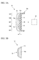
- FIG. 1 is a front view of a radiator grill 1 on which the radome 10 according to this embodiment is mounted.
- FIG. 2 is a front view of the radome 10 according to this embodiment.
- FIG. 3A is a cross-sectional view of the radome 10 taken along a line A-A of FIG. 2 .
- FIG. 3B is an enlarged view of a bright member 12 shown in FIG. 3A .
- the radome 10 is disposed on the detection side of a radar 20 that is mounted on a vehicle and detects an obstacle in the vicinity of the vehicle by using a radio wave.
- the surface of the radome 10 facing the radar 20 is referred to as a back surface
- the surface of the radome 10, which faces the front side of a vehicle on the side opposite to the back surface is referred to as a front surface.
- the detection side of the radar 20 means a direction where the radar 20 emits a radio wave. That is, the radome 10 is disposed so that a radio wave emitted from the radar 20 is transmitted through the radome 10.
- the structure of the radiator grill 1 on which the radome 10 is mounted will be described first with reference to FIG. 1 .
- the radiator grill 1 is a vehicle component that is provided on the front surface of the vehicle, and includes a plurality of members extending in a horizontal direction and a plurality of members extending in a vertical direction that are integrated with each other. Further, the radome 10 is provided in the middle of the front surface of the radiator grill 1. Meanwhile, the radar 20 is installed on the back side of the radome 10 (see FIG. 3A ).
- the radar 20 is mounted on the vehicle and detects an obstacle in the vicinity of the vehicle by using a radio wave. Specifically, the radar measures a distance, relative speed, and the like between the vehicle and an obstacle positioned on the front side of the vehicle.
- the radar 20 includes a transmitter and a receiver.
- the transmitter emits a radio wave (millimeter wave) having a frequency in the range of 76 GHz to 77 GHz, that is, a frequency that is applied to a radar for detecting an inter-vehicle distance.
- the receiver receives a radio wave reflected from an obstacle. Meanwhile, when the radio wave emitted from the radar 20 is transmitted through the radome 10, the attenuation of a radio wave occurs. The attenuation needs to be suppressed as much as possible so that the radar 20 stably operates and correctly measures a distance between a vehicle and an obstacle.
- the structure of the radome 10 will be described below with reference to FIGS. 2 , 3A, and 3B .
- the radome 10 is a member that is provided on the detection side of the radar 20 (see FIG. 3A ) and is formed in the shape of a substantially rectangular plate, and includes metal portions 10M and a colored portion 10P when seen from the front side.
- Each of the metal portions 10M has metallic brilliance, and the colored portion 10P is colored, for example, black.
- the metal portions 10M are provided at two positions in the radome 10, and extend in the horizontal direction so as to be parallel to each other. Further, an emblem or the like of a vehicle is formed of the metal portions 10M.
- the colored portion 10P is provided at an area of the radome 10 except for the metal portions 10M.
- the radome 10 includes a transparent member 11, bright members 12, and a base member 16.
- the transparent member 11 is a plate-like member that has a substantially rectangular shape when seen from the front side.
- the transparent member 11 is made of a transparent synthetic resin, such as PC (polycarbonate) or PMMA (polymethyl methacrylate), and is formed by injection molding or the like.
- the thickness of the transparent member 11 is in the range of about 1.5 mm to 10 mm.
- Hard coating or clear coating of urethane-based paint, which is to prevent damage, is performed on the front surface of the transparent member 11. Meanwhile, if the transparent member 11 is made of a transparent synthetic resin having scratch resistance, these coating processes for preventing damage do not need to be performed.
- Recesses 11b are formed on a back surface (one surface) 11a of the transparent member 11 at positions corresponding to the metal portions 10M. Bright members 12 to be described below are installed in the recesses 11b, and the recesses 11b make the metal portions 10M be seen three-dimensionally when the radome 10 is seen from the front side.
- Each of the bright members 12 is formed in the shape corresponding to the recess 11b, and is installed in the recess 11b. Contact surfaces S of the bright members 12, which come into contact with the inner surface of the recess 11b, have metallic brilliance.
- Each of the bright members 12 includes a bright member body 12a and a bright layer 13.
- the bright member body 12a is formed in the shape corresponding to the recess 11b.
- the bright member body 12a is made of a synthetic resin, such as ABS (acrylonitrile butadiene styrene), PC (polycarbonate) or PET (polyethylene terephthalate), and is formed by injection molding or the like.
- the bright member body 12a is formed so as to be substantially flush with the back surface 11 a of the transparent member 11 when being installed in the recess 11b.
- the bright layer 13 is a layer that makes each of the contact surfaces S of the bright members 12 have metallic brilliance.
- the bright layer 13 includes a metal layer that is formed by metal deposition, and a base coating layer and a top coating layer (not shown) that protect the metal layer.
- a vacuum deposition method or sputtering is used as the metal deposition.
- Indium, aluminum, tin, or the like is used as the metal to be deposited.
- a base coating layer and a top coating layer are to protect a thin brittle metal layer that is formed by deposition.
- Each of the base coating layer and the top coating layer is formed by clear coating that uses a transparent synthetic resin (which may be a colored transparent synthetic resin). Since being very thin, the metal layer of the bright layer 13 has radio wave transmittance enough for the radar 20 to detect an obstacle.
- the bright layer 13 of this embodiment has been formed by metal deposition, but a method of forming the bright layer 13 of this embodiment is not limited thereto.
- the bright layer 13 may be formed by other methods in addition to the coating that makes the bright layer 13 have sufficient radio wave transmittance and metallic brilliance.
- the base member 16 covers the back surface 11a of the transparent member 11, integrally holds the transparent member 11 and the bright members 12, and is used to mount the radome 10 on the radiator grill 1.
- the base member 16 is made of a synthetic resin, such as ABS, AES (acrylonitrile ethylene styrene), PBT (polybutylene terephthalate), PC, or PET, or composite resins thereof.
- the thickness of the base member 16 is in the range of about 0.5 mm to 10 mm.
- the base member 16 has a color (black or the like).
- the color of the base member 16 is the same as the color of the colored portion 10P of the radome 10.
- a plurality of mounting pieces 16a which is to be connected to the radiator grill 1, is formed on the back surface of the base member 16.
- the base member 16 is formed by injection molding.
- the base member 16 is formed by so-called insert molding that performs injection molding while the transparent member 11 where the bright members 12 are installed in the recesses 11b is disposed in a mold for injection molding. Meanwhile, a hot melted resin comes into contact with the back surface 11a of the transparent member 11 during the formation of the base member 16. For this reason, the transparent member 11 is slightly melted on the back surface 11a. Accordingly, after the formation of the base member 16, the transparent member 11 and the base member 16 are welded to each other on the back surface 11a. As a result, it may be possible to join the transparent member 11 to the base member 16 without using an adhesive or the like.
- FIGS. 4A to 4E are schematic views illustrating the method of manufacturing the radome 10 according to this embodiment.
- the method of manufacturing the radome 10 includes a first forming step of forming the transparent member 11, a second forming step of forming the bright members 12, a first installing step of installing the bright members 12 in the recesses 11b, and a second installing step of installing the base member 16 on the back surface 11a of the transparent member 11 while forming the base member 16.
- the transparent member 11 is formed first as shown in FIG. 4A .
- the transparent member 11 is formed by injection molding, and the recesses 11b are formed on the back surface 11a thereof. Meanwhile, the back surface 11a and the inner surfaces of the recesses 11b are formed of smooth surfaces. Further, hard coating is performed on the front surface of the transparent member 11 in order to prevent damage by improving durability against friction or the like.
- the bright members 12 are formed as shown in FIGS. 4B and 4C .
- each of the bright member bodies 12a is formed by injection molding or the like. Then, the bright layer 13 is formed on the surface 12s of each of the bright member bodies 12a corresponding to the inner surfaces of the recesses 11b. The bright layer 13 is formed by sequentially laminating the base coating layer, the metal layer, and the top coating layer on the bright member body 12a. Each of the base coating layer and the top coating layer is formed by clear coating that uses a transparent synthetic resin. The metal layer is formed by metal deposition.
- the bright members 12 are installed in the recesses 11b as shown in FIG. 4D . Meanwhile, the bright layers 13 are omitted in FIG. 4D and FIG. 4E to be described below.
- the bright members 12 are installed in the recesses 11b of the transparent member 11. In this case, the contact surfaces S of the bright members 12 come into contact with the inner surfaces of the recesses 11b without a gap.
- the base member 16 is formed as shown in FIG. 4E .
- the transparent member 11 where the bright members 12 are installed in the recesses 11b is disposed in a mold for injection molding, and the base member 16 is formed by performing insert molding that injects a melted resin to the back surface 11a of the transparent member 11. Since covering the back surface 11a, the base member 16 can integrally hold the transparent member 11 and the bright members 12. Meanwhile, the transparent member 11 is slightly melted on the back surface 11a due to the heat of the melted resin. For this reason, after the base member 16 is formed, the transparent member 11 and the base member 16 are welded to each other on the back surface 11 a. Accordingly, it may be possible to join the transparent member 11 to the base member 16 without using an adhesive or the like.
- a color (black or the like) resin is used as a resin that is used to form the base member 16. Accordingly, after the base member 16 is formed, the color of the base member 16 is the same as the color of the colored portion 10P of the radome 10. For this reason, a colored layer or the like, which forms the color of the colored portion 10P does not need to be formed on the back surface 11a.
- each of the bright members 12 is formed in the shape that has a thickness corresponding to a space in the recess 11b, and a melted resin is injected to the surface of the bright member 12 opposite to the contact surface S (bright layer 13) of the bright member 12. Accordingly, the bright layer 13 of the bright member 12 is hardly damaged.
- the bright members 12 include the bright layers 13 if the radome 10 is manufactured by the above-mentioned method, each of the bright members 12 has brilliance. For this reason, a metal layer for making the transparent member 11 have brilliance, a base coating layer and a top coating layer for protecting the metal layer, and the like do not need to be formed, the number of the steps of manufacturing the radome 10 are reduced. As a result, the number of the steps of manufacturing the radome 10 is reduced, so that the yield of products in all manufacturing steps is improved and the rate of generation of defective products is suppressed.
- the radome 10 it may be possible to reduce the number of the steps of manufacturing the radome 10 and to suppress the rate of generation of defective products. Accordingly, it may be possible to obtain an advantage of reducing the labor hours or cost that are required to manufacture the radome 10.
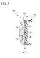
- FIG. 5 The structure of a radome 10A according to a second embodiment of the present invention will be described with reference to FIG. 5 . Meanwhile, in FIG. 5 , the same components as those of the first embodiment shown in FIGS. 3A and 3B are represented by the same reference numerals, and description thereof will be omitted.
- FIG. 5 is a cross-sectional view of the radome 10A according to this embodiment.
- the colored layer 14 is formed by silk screen printing, hot stamp, pad printing, or the like.
- An adhesive 15 is disposed between the transparent member 11 and the bright members 12, and the base member 16. That is, the transparent member 11 and the bright members 12 are bonded to the base member 16 by the adhesive 15.
- An adhesive or a pressure sensitive adhesive which bonds an object by being hardened from the form of a liquid or gel, a double-sided tape, or the like, is used as the adhesive 15.
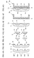
- FIGS. 6A to 6G are schematic views illustrating the method of manufacturing the radome 10A according to this embodiment.
- the method of manufacturing the radome 10A includes a first forming step of forming the transparent member 11, a step of forming the colored layer 14 on the transparent member 11, a second forming step of forming the bright members 12, a first installing step of installing the bright members 12 in the recesses 11b, a step of forming the base member 16 and applying the adhesive 15 to the base member 16, and a second installing step of installing the base member 16 on the back surface 11a of the transparent member 11 by the adhesive 15.
- the transparent member 11 is formed first as shown in FIG. 6A .
- the colored layer 14 is formed as shown in FIG. 6B .
- the colored layer 14 is formed on the back surface 11a of the transparent member 11. In this case, the colored layer 14 is not formed on the inner surfaces of the recesses 11b.
- the colored layer 14 is formed by silk screen printing, hot stamp, pad printing, or the like. It may be possible to adjust the color of the colored portion 10P of the radome 10A by forming the colored layer 14.
- the bright members 12 are formed as shown in FIGS. 6C and 6D .
- the bright members 12 are installed in the recesses 11b as shown in FIG. 6E .
- the bright layers 13 are omitted in FIG. 6E and FIG. 6G to be described below.
- the base member 16 is formed and the adhesive 15 is applied as shown in FIG. 6F .
- the base member 16 is formed by injection molding or the like. Then, the adhesive 15 is applied to the surface of the base member 16, which is bonded to the transparent member 11.
- An adhesive or a pressure sensitive adhesive which bonds an object by being hardened from the form of a liquid or gel, a double-sided tape, or the like, is used as the adhesive 15 of this embodiment.
- the base member 16 is bonded to the back surface 11a of the transparent member 11 by the adhesive 15.
- the base member 16 can integrally hold the transparent member 11 and the bright members 12. Further, in this embodiment, the previously formed base member 16 is bonded to the transparent member 11 and the bright members 12 by the adhesive 15. Accordingly, the transparent member 11, or the bright members 12, particularly, the bright layers 13 are not damaged. Furthermore, labor hours or cost, which are required to manufacture the radome 10A, are reduced as compared to when the base member 16 is formed by injection molding.
- the bright member 12 is smaller than the transparent member 11. Accordingly, as compared to when a transparent portion is decorated, it may be possible to further reduce loss when defectives are generated in a decorating step.
- the structure of the bright member 12 is simple. Accordingly, it may be possible to further reduce the time that is required to perform molding and decoration. Therefore, it may be possible to perform the formation and decoration of the bright members 12 and the transparent member 11 in parallel, and to reduce the number of the steps of manufacturing the radome 10A.
- the base member 16 has been formed by insert molding in the first embodiment, but a method of forming the base member 16 is not limited thereto.
- the base member 16 may be formed by so-called two-color molding (double molding) or DSI molding (Die Slide Injection molding).
- double molding double molding
- DSI molding Die Slide Injection molding
- the bright members 12 are installed in the recesses 11b while the formed transparent member 11 is disposed in a mold
- the base member 16 continues to be molded while only a mold for the base member 16 is exchanged. According to this method, it may be possible to further reduce the number of the steps of manufacturing the radome 10.
- the transparent member 11 and the base member 16 have come into direct contact with each other and have been directly welded to each other on the back surface 11a.
- the present invention is not limited to this structure. A modification of the radome 10 shown in FIG. 7 may be employed.
- a colored layer 14 is formed on a back surface 11a of a transparent member 11 in order to adjust the color of a colored portion 10P of the radome 10. Meanwhile, if it is not possible to secure a sufficient joining force between the transparent member 11 and the base member 16 by forming the colored layer 14, an adhesive (not shown in FIG. 7 ) may be provided between the transparent member 11 and the base member 16.
- the plurality of mounting pieces 16a which is to be connected to the radiator grill 1, has been formed at the base member 16.
- the present invention is not limited to this structure. A modification of the radome 10A shown in FIG. 8 may be employed.
- a second adhesive 17 is provided instead of the mounting pieces 16a and the radome 10 is connected to the radiator grill 1 by the second adhesive 17. Meanwhile, second adhesive 17 may be applied to the radome 10 according to the first embodiment.
- the radome 10(10A) has been mounted on the radiator grill 1.
- the present invention is not limited to this structure.
- the radome 10(10A) may be provided on, for example, a bumper or the like of a vehicle.
Landscapes
- Engineering & Computer Science (AREA)
- Computer Networks & Wireless Communication (AREA)
- Physics & Mathematics (AREA)
- General Physics & Mathematics (AREA)
- Radar, Positioning & Navigation (AREA)
- Remote Sensing (AREA)
- Manufacturing & Machinery (AREA)
- Mechanical Engineering (AREA)
- Details Of Aerials (AREA)
- Injection Moulding Of Plastics Or The Like (AREA)
- Support Of Aerials (AREA)
- Radar Systems Or Details Thereof (AREA)
Applications Claiming Priority (1)
| Application Number | Priority Date | Filing Date | Title |
|---|---|---|---|
| JP2009199040A JP4881984B2 (ja) | 2009-08-28 | 2009-08-28 | レドームの製造方法 |
Publications (2)
| Publication Number | Publication Date |
|---|---|
| EP2293382A1 true EP2293382A1 (de) | 2011-03-09 |
| EP2293382B1 EP2293382B1 (de) | 2019-06-19 |
Family
ID=43333041
Family Applications (1)
| Application Number | Title | Priority Date | Filing Date |
|---|---|---|---|
| EP10173748.4A Active EP2293382B1 (de) | 2009-08-28 | 2010-08-23 | Verfahren zur Herstellung eines Radoms |
Country Status (5)
| Country | Link |
|---|---|
| US (1) | US8974712B2 (de) |
| EP (1) | EP2293382B1 (de) |
| JP (1) | JP4881984B2 (de) |
| KR (1) | KR101673035B1 (de) |
| CN (1) | CN102005647B (de) |
Cited By (7)
| Publication number | Priority date | Publication date | Assignee | Title |
|---|---|---|---|---|
| EP3300169A3 (de) * | 2016-09-27 | 2018-04-04 | Faltec Co., Ltd. | Radarabdeckung und verfahren zur herstellung der radarabdeckung |
| WO2018130402A1 (de) * | 2017-01-10 | 2018-07-19 | Audi Ag | Radaranordnung für ein kraftfahrzeug und kraftfahrzeug |
| EP3346283A4 (de) * | 2015-08-31 | 2019-03-20 | Faltec Co., Ltd. | Radarabdeckungsherstellungsverfahren und radarabdeckung |
| EP3565058A1 (de) * | 2016-10-21 | 2019-11-06 | Toyoda Gosei Co., Ltd. | Zierteil für fahrzeug und verfahren zur herstellung davon |
| EP3530524A4 (de) * | 2016-11-30 | 2020-10-21 | Faltec Co., Ltd. | Radarabdeckung und verfahren zur herstellung der radarabdeckung |
| EP3933431A4 (de) * | 2019-02-28 | 2022-12-28 | Faltec Co., Ltd. | Radarabdeckung |
| WO2023191750A1 (en) * | 2022-03-29 | 2023-10-05 | Istanbul Teknik Universitesi | Technique for the improvement of broadband (500 mhz - 50 ghz) dielectric coefficient of pmma / borax composite synthesized by atrp method and its hydrophilic properties modified and potential application areas |
Families Citing this family (55)
| Publication number | Priority date | Publication date | Assignee | Title |
|---|---|---|---|---|
| DE102011053104A1 (de) * | 2011-08-30 | 2013-02-28 | Hella Kgaa Hueck & Co. | Radom |
| JP2013195086A (ja) * | 2012-03-15 | 2013-09-30 | Komatsu Ltd | 障害物検出機構付きダンプトラック |
| WO2013177756A1 (zh) * | 2012-05-30 | 2013-12-05 | 湖州赫特金泰汽车零部件有限公司 | 一种雷达保护罩及其制造方法 |
| JP2014069634A (ja) * | 2012-09-28 | 2014-04-21 | Toyoda Gosei Co Ltd | 車両用加飾部材 |
| US20140184068A1 (en) * | 2012-12-27 | 2014-07-03 | Young Chul Kwon | Bi-color Illuminated Emblem |
| KR101459910B1 (ko) * | 2013-05-28 | 2014-11-07 | 현대자동차주식회사 | 차량용 레이더장치 |
| DE102013220259A1 (de) * | 2013-10-08 | 2015-04-09 | Robert Bosch Gmbh | Radarsensor mit Radom |
| JP2015099081A (ja) * | 2013-11-19 | 2015-05-28 | 豊田合成株式会社 | 電波透過カバー及び電波透過カバーの製造方法 |
| US9673517B2 (en) | 2014-04-30 | 2017-06-06 | Honda Motor Co., Ltd. | Vehicle radar cover assembly and method |
| CN103956573B (zh) * | 2014-05-21 | 2016-02-24 | 湖州泰和汽车零部件有限公司 | 一种雷达保护罩的制备方法 |
| JPWO2016052146A1 (ja) * | 2014-09-29 | 2017-04-27 | 豊田合成株式会社 | 装飾めっき製品、取付構造、製造方法、及び取り付け方法 |
| JP6216708B2 (ja) * | 2014-12-26 | 2017-10-18 | 株式会社ファルテック | レーダカバーの製造方法及びレーダカバー |
| JP6155249B2 (ja) * | 2014-12-26 | 2017-06-28 | 株式会社ファルテック | グリルシャッタモジュール |
| JP6518104B2 (ja) * | 2015-03-26 | 2019-05-22 | 株式会社ファルテック | 車両用装着品 |
| US20170008251A1 (en) * | 2015-07-08 | 2017-01-12 | Raytheon Company | High performance plastic radome |
| US10351077B2 (en) * | 2015-08-25 | 2019-07-16 | Mazda Motor Corporation | Vehicle member |
| CN105109417A (zh) * | 2015-08-26 | 2015-12-02 | 宁波邦盛汽车零部件有限公司 | 汽车自适应主动巡航系统雷达的覆盖件 |
| JP6343594B2 (ja) * | 2015-08-31 | 2018-06-13 | 株式会社ファルテック | レーダカバーの製造方法及びレーダカバー |
| DE102015217744A1 (de) * | 2015-09-16 | 2017-03-16 | Nanogate PD Systems GmbH | Radom |
| US9828036B2 (en) | 2015-11-24 | 2017-11-28 | Srg Global Inc. | Active grille shutter system with integrated radar |
| US20170324157A1 (en) * | 2016-05-03 | 2017-11-09 | Srg Global Inc. | Three piece vehicle radome |
| JP6093470B1 (ja) * | 2016-08-01 | 2017-03-08 | サカエ理研工業株式会社 | 電波透過カバー |
| JP2018035402A (ja) * | 2016-08-31 | 2018-03-08 | 株式会社ファルテック | レーダカバーの製造方法 |
| DE102016217057A1 (de) * | 2016-09-08 | 2018-03-08 | Robert Bosch Gmbh | Radarmodul für ein Fahrzeug |
| US10090588B2 (en) | 2016-09-26 | 2018-10-02 | Srg Global Inc. | Selectively chrome plated vehicle radome and vehicle radiator grille and methods of manufacturing |
| DE102016012182A1 (de) * | 2016-10-12 | 2018-04-12 | Audi Ag | Sensoranordnung |
| US20180159207A1 (en) * | 2016-12-02 | 2018-06-07 | Srg Global Inc. | Multi-piece vehicle radome having non-uniform back piece |
| WO2018105644A1 (ja) * | 2016-12-09 | 2018-06-14 | 株式会社ファルテック | レーダカバー及びレーダカバーの製造方法 |
| EP3527430A4 (de) | 2016-12-27 | 2020-10-21 | Faltec Co., Ltd. | Radarabdeckung und verfahren zur herstellung der radarabdeckung |
| DE102017201660A1 (de) * | 2017-02-02 | 2018-08-02 | Robert Bosch Gmbh | Verfahren zur Herstellung einer leuchtenden 3D-Radarmodulabdeckung und Spritzgieß-Anordnung |
| JP2018159585A (ja) * | 2017-03-22 | 2018-10-11 | 株式会社ファルテック | レーダカバー及びレーダカバーの製造方法 |
| JP2018159584A (ja) * | 2017-03-22 | 2018-10-11 | 株式会社ファルテック | レーダカバーの製造方法及びレーダカバー |
| KR102413208B1 (ko) * | 2017-09-11 | 2022-06-27 | 현대자동차주식회사 | 이종색상을 구비한 차량용 라디에이터 |
| WO2019064330A1 (ja) * | 2017-09-26 | 2019-04-04 | 河西工業株式会社 | 外装用加飾部品及び外装用加飾部品の製造方法 |
| KR101856441B1 (ko) * | 2017-09-29 | 2018-05-10 | 인탑스 주식회사 | 자동차용 크루즈컨트롤 센서 커버 및 그 제조방법 |
| JP6883503B2 (ja) * | 2017-10-10 | 2021-06-09 | 株式会社ファルテック | レーダカバー及びレーダカバーユニット |
| JP6872469B2 (ja) * | 2017-11-14 | 2021-05-19 | 株式会社ファルテック | ライダーカバー |
| CN108039581A (zh) * | 2017-11-29 | 2018-05-15 | 中国航空工业集团公司济南特种结构研究所 | 一种天线罩和预埋金属环的连接结构和连接方法 |
| US11073600B2 (en) | 2017-12-22 | 2021-07-27 | Robert Bosch Gmbh | Radar sensor |
| JP6868549B2 (ja) * | 2017-12-28 | 2021-05-12 | 株式会社ファルテック | レーダカバー |
| JP2019128255A (ja) * | 2018-01-24 | 2019-08-01 | 株式会社ファルテック | レーダカバー及びレーダカバーの製造方法 |
| CN111344590A (zh) * | 2018-01-30 | 2020-06-26 | 古野电气株式会社 | 雷达天线装置以及方位测定方法 |
| CN108515660B (zh) * | 2018-03-13 | 2020-07-24 | 嘉兴敏胜汽车零部件有限公司 | 一种汽车自动巡航雷达遮盖件加工方法 |
| JP7154123B2 (ja) * | 2018-08-30 | 2022-10-17 | 株式会社ファルテック | レーダカバー |
| JP2020067291A (ja) * | 2018-10-22 | 2020-04-30 | 豊田合成株式会社 | 車載センサカバー |
| JP7149832B2 (ja) * | 2018-12-11 | 2022-10-07 | 株式会社ファルテック | レーダカバー及びレーダカバーの製造方法 |
| CN109828260A (zh) * | 2019-03-28 | 2019-05-31 | 福建富兰光学有限公司 | 一种光学功能面及其应用所述光学功能面的激光雷达外罩 |
| JP7101634B2 (ja) * | 2019-03-29 | 2022-07-15 | 本田技研工業株式会社 | 樹脂成形品 |
| US11495880B2 (en) | 2019-04-18 | 2022-11-08 | Srg Global, Llc | Stepped radar cover and method of manufacture |
| JP7034123B2 (ja) * | 2019-06-28 | 2022-03-11 | 株式会社ファルテック | レーダカバー |
| EP4005022A1 (de) * | 2019-07-29 | 2022-06-01 | Motherson Innovations Company Limited | Erste oberfläche oder zweite oberfläche eines dekorativen radoms |
| EP4028790A1 (de) * | 2019-09-11 | 2022-07-20 | HELLA Saturnus Slovenija d.o.o. | Vorrichtung zur befestigung an einer öffnung eines fahrzeuges und zum abdecken eines senders und/oder eines empfängers |
| US20220384940A1 (en) * | 2019-10-15 | 2022-12-01 | Motherson Innovations Company Limited | First Surface Decorative Element |
| ES2950833T3 (es) * | 2020-08-17 | 2023-10-13 | Zanini Auto Grup Sa | Radomo para vehículos |
| ES2946043A1 (es) * | 2022-01-12 | 2023-07-12 | Srg Global Liria S L | Rejilla iluminada tipo radomo |
Citations (4)
| Publication number | Priority date | Publication date | Assignee | Title |
|---|---|---|---|---|
| JP2000049522A (ja) | 1998-05-02 | 2000-02-18 | Daimlerchrysler Ag | 距離警告レーダのレードームを製作する方法 |
| JP2000159039A (ja) | 1998-09-25 | 2000-06-13 | Daimlerchrysler Ag | レ―ダ装置のビ―ム経路内にある被覆部品 |
| US20050062660A1 (en) * | 2003-09-23 | 2005-03-24 | Henderson Mark F. | Apparatus for shaping the radiation pattern of a planar antenna near-field radar system |
| EP1635187A2 (de) * | 2002-08-22 | 2006-03-15 | Hitachi, Ltd. | Millimeterwellen-Radar mit nebenkeulenabsorbierendem Radom |
Family Cites Families (10)
| Publication number | Priority date | Publication date | Assignee | Title |
|---|---|---|---|---|
| JP4099946B2 (ja) * | 2001-01-11 | 2008-06-11 | 株式会社ファルテック | 金属光輝色を呈する成形品の製造方法 |
| JP4022819B2 (ja) * | 2002-12-26 | 2007-12-19 | 豊田合成株式会社 | 電波透過カバー |
| JP4158646B2 (ja) * | 2003-08-06 | 2008-10-01 | トヨタ自動車株式会社 | 自動車フロントグリル及びその製造方法 |
| JP2005249773A (ja) * | 2004-02-02 | 2005-09-15 | Toyota Motor Corp | レーダ装置ビーム経路内用成形品 |
| JP2005212745A (ja) * | 2004-02-02 | 2005-08-11 | Toyota Motor Corp | レーダ装置ビーム経路内用成形品 |
| JP2007013722A (ja) * | 2005-06-30 | 2007-01-18 | Toyoda Gosei Co Ltd | 電波レーダ装置のビーム経路に配置される樹脂成形品とその製造方法 |
| JP4706596B2 (ja) * | 2005-10-31 | 2011-06-22 | 豊田合成株式会社 | 樹脂製品及びその製造方法並びに金属皮膜の成膜方法 |
| JP4732147B2 (ja) * | 2005-11-21 | 2011-07-27 | 豊田合成株式会社 | 樹脂製品及びその製造方法並びに金属皮膜の成膜方法 |
| JP2008024254A (ja) * | 2006-07-25 | 2008-02-07 | Mazda Motor Corp | 車両の外装部品及びその製造方法 |
| JP2008195161A (ja) * | 2007-02-09 | 2008-08-28 | Mazda Motor Corp | 車両の外装部品 |
-
2009
- 2009-08-28 JP JP2009199040A patent/JP4881984B2/ja active Active
-
2010
- 2010-08-23 EP EP10173748.4A patent/EP2293382B1/de active Active
- 2010-08-24 US US12/861,933 patent/US8974712B2/en active Active
- 2010-08-26 KR KR1020100082968A patent/KR101673035B1/ko active IP Right Grant
- 2010-08-26 CN CN201010265987.1A patent/CN102005647B/zh active Active
Patent Citations (4)
| Publication number | Priority date | Publication date | Assignee | Title |
|---|---|---|---|---|
| JP2000049522A (ja) | 1998-05-02 | 2000-02-18 | Daimlerchrysler Ag | 距離警告レーダのレードームを製作する方法 |
| JP2000159039A (ja) | 1998-09-25 | 2000-06-13 | Daimlerchrysler Ag | レ―ダ装置のビ―ム経路内にある被覆部品 |
| EP1635187A2 (de) * | 2002-08-22 | 2006-03-15 | Hitachi, Ltd. | Millimeterwellen-Radar mit nebenkeulenabsorbierendem Radom |
| US20050062660A1 (en) * | 2003-09-23 | 2005-03-24 | Henderson Mark F. | Apparatus for shaping the radiation pattern of a planar antenna near-field radar system |
Cited By (13)
| Publication number | Priority date | Publication date | Assignee | Title |
|---|---|---|---|---|
| EP3346283A4 (de) * | 2015-08-31 | 2019-03-20 | Faltec Co., Ltd. | Radarabdeckungsherstellungsverfahren und radarabdeckung |
| US10431884B2 (en) | 2016-09-27 | 2019-10-01 | Faltec Co. Ltd. | Radar cover and method of manufacturing radar cover |
| EP3300169A3 (de) * | 2016-09-27 | 2018-04-04 | Faltec Co., Ltd. | Radarabdeckung und verfahren zur herstellung der radarabdeckung |
| US10974661B2 (en) | 2016-10-21 | 2021-04-13 | Toyoda Gosei Co., Ltd. | Decorative part for vehicle and method for manufacturing same |
| EP3565058A1 (de) * | 2016-10-21 | 2019-11-06 | Toyoda Gosei Co., Ltd. | Zierteil für fahrzeug und verfahren zur herstellung davon |
| US11267410B2 (en) | 2016-10-21 | 2022-03-08 | Toyoda Gosei Co., Ltd. | Decorative part for vehicle and method for manufacturing same |
| US11634089B2 (en) | 2016-10-21 | 2023-04-25 | Toyoda Gosei Co., Ltd. | Decorative part for vehicle and method for manufacturing same |
| US11648889B2 (en) | 2016-10-21 | 2023-05-16 | Toyoda Gosei Co., Ltd. | Decorative part for vehicle and method for manufacturing same |
| EP3530524A4 (de) * | 2016-11-30 | 2020-10-21 | Faltec Co., Ltd. | Radarabdeckung und verfahren zur herstellung der radarabdeckung |
| WO2018130402A1 (de) * | 2017-01-10 | 2018-07-19 | Audi Ag | Radaranordnung für ein kraftfahrzeug und kraftfahrzeug |
| US11561301B2 (en) | 2017-01-10 | 2023-01-24 | Audi Ag | Radar arrangement for a motor vehicle, and motor vehicle |
| EP3933431A4 (de) * | 2019-02-28 | 2022-12-28 | Faltec Co., Ltd. | Radarabdeckung |
| WO2023191750A1 (en) * | 2022-03-29 | 2023-10-05 | Istanbul Teknik Universitesi | Technique for the improvement of broadband (500 mhz - 50 ghz) dielectric coefficient of pmma / borax composite synthesized by atrp method and its hydrophilic properties modified and potential application areas |
Also Published As
| Publication number | Publication date |
|---|---|
| US20110047784A1 (en) | 2011-03-03 |
| US8974712B2 (en) | 2015-03-10 |
| KR20110023788A (ko) | 2011-03-08 |
| JP4881984B2 (ja) | 2012-02-22 |
| KR101673035B1 (ko) | 2016-11-04 |
| CN102005647B (zh) | 2015-04-22 |
| JP2011046183A (ja) | 2011-03-10 |
| EP2293382B1 (de) | 2019-06-19 |
| CN102005647A (zh) | 2011-04-06 |
Similar Documents
| Publication | Publication Date | Title |
|---|---|---|
| EP2293382B1 (de) | Verfahren zur Herstellung eines Radoms | |
| JP5460218B2 (ja) | レドームの製造方法 | |
| CN111527009B (zh) | 用于机动车辆的前格栅的雷达透明装饰板 | |
| EP3248751B1 (de) | Verfahren zur herstellung einer radarabdeckung sowie radarabdeckung | |
| EP3300169B1 (de) | Radarabdeckung und verfahren zur herstellung der radarabdeckung | |
| JP6518104B2 (ja) | 車両用装着品 | |
| US10351077B2 (en) | Vehicle member | |
| US20150140259A1 (en) | Radio-wave transparent cover and method for manufacturing radio-wave transparent cover | |
| US20140093665A1 (en) | Decorative member for vehicle | |
| JP2007013722A (ja) | 電波レーダ装置のビーム経路に配置される樹脂成形品とその製造方法 | |
| JP2010111011A (ja) | 車両用電波透過カバー、及び車両用電波透過カバーの製造方法 | |
| CN107949794B (zh) | 雷达罩的制造方法以及雷达罩 | |
| WO2017038550A1 (ja) | レーダカバーの製造方法及びレーダカバー | |
| WO2019064330A1 (ja) | 外装用加飾部品及び外装用加飾部品の製造方法 | |
| EP3933431A1 (de) | Radarabdeckung | |
| JP7063842B2 (ja) | レーダカバー及びレーダカバーの製造方法 | |
| JP7034123B2 (ja) | レーダカバー | |
| JP6868549B2 (ja) | レーダカバー | |
| KR20230082380A (ko) | 엠블럼 디자인을 갖춘 자동차용 스마트 크루즈 콘트롤커버 제조방법 | |
| JP2019184615A (ja) | レーダカバー及びレーダカバーの製造方法 |
Legal Events
| Date | Code | Title | Description |
|---|---|---|---|
| PUAI | Public reference made under article 153(3) epc to a published international application that has entered the european phase |
Free format text: ORIGINAL CODE: 0009012 |
|
| AK | Designated contracting states |
Kind code of ref document: A1 Designated state(s): AL AT BE BG CH CY CZ DE DK EE ES FI FR GB GR HR HU IE IS IT LI LT LU LV MC MK MT NL NO PL PT RO SE SI SK SM TR |
|
| AX | Request for extension of the european patent |
Extension state: BA ME RS |
|
| 17P | Request for examination filed |
Effective date: 20110905 |
|
| 17Q | First examination report despatched |
Effective date: 20150327 |
|
| STAA | Information on the status of an ep patent application or granted ep patent |
Free format text: STATUS: EXAMINATION IS IN PROGRESS |
|
| GRAP | Despatch of communication of intention to grant a patent |
Free format text: ORIGINAL CODE: EPIDOSNIGR1 |
|
| STAA | Information on the status of an ep patent application or granted ep patent |
Free format text: STATUS: GRANT OF PATENT IS INTENDED |
|
| RIC1 | Information provided on ipc code assigned before grant |
Ipc: H01Q 1/42 20060101AFI20181211BHEP Ipc: G01S 7/03 20060101ALI20181211BHEP Ipc: G01S 13/93 20060101ALI20181211BHEP |
|
| INTG | Intention to grant announced |
Effective date: 20190108 |
|
| GRAS | Grant fee paid |
Free format text: ORIGINAL CODE: EPIDOSNIGR3 |
|
| GRAA | (expected) grant |
Free format text: ORIGINAL CODE: 0009210 |
|
| STAA | Information on the status of an ep patent application or granted ep patent |
Free format text: STATUS: THE PATENT HAS BEEN GRANTED |
|
| AK | Designated contracting states |
Kind code of ref document: B1 Designated state(s): AL AT BE BG CH CY CZ DE DK EE ES FI FR GB GR HR HU IE IS IT LI LT LU LV MC MK MT NL NO PL PT RO SE SI SK SM TR |
|
| REG | Reference to a national code |
Ref country code: GB Ref legal event code: FG4D |
|
| REG | Reference to a national code |
Ref country code: CH Ref legal event code: EP |
|
| REG | Reference to a national code |
Ref country code: IE Ref legal event code: FG4D |
|
| REG | Reference to a national code |
Ref country code: DE Ref legal event code: R096 Ref document number: 602010059507 Country of ref document: DE |
|
| REG | Reference to a national code |
Ref country code: AT Ref legal event code: REF Ref document number: 1146680 Country of ref document: AT Kind code of ref document: T Effective date: 20190715 |
|
| REG | Reference to a national code |
Ref country code: NL Ref legal event code: MP Effective date: 20190619 |
|
| PG25 | Lapsed in a contracting state [announced via postgrant information from national office to epo] |
Ref country code: LT Free format text: LAPSE BECAUSE OF FAILURE TO SUBMIT A TRANSLATION OF THE DESCRIPTION OR TO PAY THE FEE WITHIN THE PRESCRIBED TIME-LIMIT Effective date: 20190619 Ref country code: HR Free format text: LAPSE BECAUSE OF FAILURE TO SUBMIT A TRANSLATION OF THE DESCRIPTION OR TO PAY THE FEE WITHIN THE PRESCRIBED TIME-LIMIT Effective date: 20190619 Ref country code: FI Free format text: LAPSE BECAUSE OF FAILURE TO SUBMIT A TRANSLATION OF THE DESCRIPTION OR TO PAY THE FEE WITHIN THE PRESCRIBED TIME-LIMIT Effective date: 20190619 Ref country code: NO Free format text: LAPSE BECAUSE OF FAILURE TO SUBMIT A TRANSLATION OF THE DESCRIPTION OR TO PAY THE FEE WITHIN THE PRESCRIBED TIME-LIMIT Effective date: 20190919 Ref country code: AL Free format text: LAPSE BECAUSE OF FAILURE TO SUBMIT A TRANSLATION OF THE DESCRIPTION OR TO PAY THE FEE WITHIN THE PRESCRIBED TIME-LIMIT Effective date: 20190619 Ref country code: SE Free format text: LAPSE BECAUSE OF FAILURE TO SUBMIT A TRANSLATION OF THE DESCRIPTION OR TO PAY THE FEE WITHIN THE PRESCRIBED TIME-LIMIT Effective date: 20190619 |
|
| REG | Reference to a national code |
Ref country code: LT Ref legal event code: MG4D |
|
| PG25 | Lapsed in a contracting state [announced via postgrant information from national office to epo] |
Ref country code: BG Free format text: LAPSE BECAUSE OF FAILURE TO SUBMIT A TRANSLATION OF THE DESCRIPTION OR TO PAY THE FEE WITHIN THE PRESCRIBED TIME-LIMIT Effective date: 20190919 Ref country code: GR Free format text: LAPSE BECAUSE OF FAILURE TO SUBMIT A TRANSLATION OF THE DESCRIPTION OR TO PAY THE FEE WITHIN THE PRESCRIBED TIME-LIMIT Effective date: 20190920 Ref country code: LV Free format text: LAPSE BECAUSE OF FAILURE TO SUBMIT A TRANSLATION OF THE DESCRIPTION OR TO PAY THE FEE WITHIN THE PRESCRIBED TIME-LIMIT Effective date: 20190619 |
|
| REG | Reference to a national code |
Ref country code: AT Ref legal event code: MK05 Ref document number: 1146680 Country of ref document: AT Kind code of ref document: T Effective date: 20190619 |
|
| PG25 | Lapsed in a contracting state [announced via postgrant information from national office to epo] |
Ref country code: EE Free format text: LAPSE BECAUSE OF FAILURE TO SUBMIT A TRANSLATION OF THE DESCRIPTION OR TO PAY THE FEE WITHIN THE PRESCRIBED TIME-LIMIT Effective date: 20190619 Ref country code: SK Free format text: LAPSE BECAUSE OF FAILURE TO SUBMIT A TRANSLATION OF THE DESCRIPTION OR TO PAY THE FEE WITHIN THE PRESCRIBED TIME-LIMIT Effective date: 20190619 Ref country code: AT Free format text: LAPSE BECAUSE OF FAILURE TO SUBMIT A TRANSLATION OF THE DESCRIPTION OR TO PAY THE FEE WITHIN THE PRESCRIBED TIME-LIMIT Effective date: 20190619 Ref country code: PT Free format text: LAPSE BECAUSE OF FAILURE TO SUBMIT A TRANSLATION OF THE DESCRIPTION OR TO PAY THE FEE WITHIN THE PRESCRIBED TIME-LIMIT Effective date: 20191021 Ref country code: RO Free format text: LAPSE BECAUSE OF FAILURE TO SUBMIT A TRANSLATION OF THE DESCRIPTION OR TO PAY THE FEE WITHIN THE PRESCRIBED TIME-LIMIT Effective date: 20190619 Ref country code: NL Free format text: LAPSE BECAUSE OF FAILURE TO SUBMIT A TRANSLATION OF THE DESCRIPTION OR TO PAY THE FEE WITHIN THE PRESCRIBED TIME-LIMIT Effective date: 20190619 Ref country code: CZ Free format text: LAPSE BECAUSE OF FAILURE TO SUBMIT A TRANSLATION OF THE DESCRIPTION OR TO PAY THE FEE WITHIN THE PRESCRIBED TIME-LIMIT Effective date: 20190619 |
|
| PG25 | Lapsed in a contracting state [announced via postgrant information from national office to epo] |
Ref country code: SM Free format text: LAPSE BECAUSE OF FAILURE TO SUBMIT A TRANSLATION OF THE DESCRIPTION OR TO PAY THE FEE WITHIN THE PRESCRIBED TIME-LIMIT Effective date: 20190619 Ref country code: IS Free format text: LAPSE BECAUSE OF FAILURE TO SUBMIT A TRANSLATION OF THE DESCRIPTION OR TO PAY THE FEE WITHIN THE PRESCRIBED TIME-LIMIT Effective date: 20191019 Ref country code: IT Free format text: LAPSE BECAUSE OF FAILURE TO SUBMIT A TRANSLATION OF THE DESCRIPTION OR TO PAY THE FEE WITHIN THE PRESCRIBED TIME-LIMIT Effective date: 20190619 Ref country code: ES Free format text: LAPSE BECAUSE OF FAILURE TO SUBMIT A TRANSLATION OF THE DESCRIPTION OR TO PAY THE FEE WITHIN THE PRESCRIBED TIME-LIMIT Effective date: 20190619 |
|
| PG25 | Lapsed in a contracting state [announced via postgrant information from national office to epo] |
Ref country code: TR Free format text: LAPSE BECAUSE OF FAILURE TO SUBMIT A TRANSLATION OF THE DESCRIPTION OR TO PAY THE FEE WITHIN THE PRESCRIBED TIME-LIMIT Effective date: 20190619 |
|
| PG25 | Lapsed in a contracting state [announced via postgrant information from national office to epo] |
Ref country code: DK Free format text: LAPSE BECAUSE OF FAILURE TO SUBMIT A TRANSLATION OF THE DESCRIPTION OR TO PAY THE FEE WITHIN THE PRESCRIBED TIME-LIMIT Effective date: 20190619 Ref country code: PL Free format text: LAPSE BECAUSE OF FAILURE TO SUBMIT A TRANSLATION OF THE DESCRIPTION OR TO PAY THE FEE WITHIN THE PRESCRIBED TIME-LIMIT Effective date: 20190619 |
|
| PG25 | Lapsed in a contracting state [announced via postgrant information from national office to epo] |
Ref country code: CH Free format text: LAPSE BECAUSE OF NON-PAYMENT OF DUE FEES Effective date: 20190831 Ref country code: LU Free format text: LAPSE BECAUSE OF NON-PAYMENT OF DUE FEES Effective date: 20190823 Ref country code: IS Free format text: LAPSE BECAUSE OF FAILURE TO SUBMIT A TRANSLATION OF THE DESCRIPTION OR TO PAY THE FEE WITHIN THE PRESCRIBED TIME-LIMIT Effective date: 20200224 Ref country code: MC Free format text: LAPSE BECAUSE OF FAILURE TO SUBMIT A TRANSLATION OF THE DESCRIPTION OR TO PAY THE FEE WITHIN THE PRESCRIBED TIME-LIMIT Effective date: 20190619 Ref country code: LI Free format text: LAPSE BECAUSE OF NON-PAYMENT OF DUE FEES Effective date: 20190831 |
|
| REG | Reference to a national code |
Ref country code: BE Ref legal event code: MM Effective date: 20190831 |
|
| REG | Reference to a national code |
Ref country code: DE Ref legal event code: R097 Ref document number: 602010059507 Country of ref document: DE |
|
| PLBE | No opposition filed within time limit |
Free format text: ORIGINAL CODE: 0009261 |
|
| STAA | Information on the status of an ep patent application or granted ep patent |
Free format text: STATUS: NO OPPOSITION FILED WITHIN TIME LIMIT |
|
| PG2D | Information on lapse in contracting state deleted |
Ref country code: IS |
|
| PG25 | Lapsed in a contracting state [announced via postgrant information from national office to epo] |
Ref country code: IE Free format text: LAPSE BECAUSE OF NON-PAYMENT OF DUE FEES Effective date: 20190823 |
|
| 26N | No opposition filed |
Effective date: 20200603 |
|
| PG25 | Lapsed in a contracting state [announced via postgrant information from national office to epo] |
Ref country code: SI Free format text: LAPSE BECAUSE OF FAILURE TO SUBMIT A TRANSLATION OF THE DESCRIPTION OR TO PAY THE FEE WITHIN THE PRESCRIBED TIME-LIMIT Effective date: 20190619 Ref country code: BE Free format text: LAPSE BECAUSE OF NON-PAYMENT OF DUE FEES Effective date: 20190831 |
|
| PG25 | Lapsed in a contracting state [announced via postgrant information from national office to epo] |
Ref country code: CY Free format text: LAPSE BECAUSE OF FAILURE TO SUBMIT A TRANSLATION OF THE DESCRIPTION OR TO PAY THE FEE WITHIN THE PRESCRIBED TIME-LIMIT Effective date: 20190619 |
|
| PG25 | Lapsed in a contracting state [announced via postgrant information from national office to epo] |
Ref country code: HU Free format text: LAPSE BECAUSE OF FAILURE TO SUBMIT A TRANSLATION OF THE DESCRIPTION OR TO PAY THE FEE WITHIN THE PRESCRIBED TIME-LIMIT; INVALID AB INITIO Effective date: 20100823 Ref country code: MT Free format text: LAPSE BECAUSE OF FAILURE TO SUBMIT A TRANSLATION OF THE DESCRIPTION OR TO PAY THE FEE WITHIN THE PRESCRIBED TIME-LIMIT Effective date: 20190619 |
|
| PG25 | Lapsed in a contracting state [announced via postgrant information from national office to epo] |
Ref country code: MK Free format text: LAPSE BECAUSE OF FAILURE TO SUBMIT A TRANSLATION OF THE DESCRIPTION OR TO PAY THE FEE WITHIN THE PRESCRIBED TIME-LIMIT Effective date: 20190619 |
|
| PGFP | Annual fee paid to national office [announced via postgrant information from national office to epo] |
Ref country code: GB Payment date: 20230629 Year of fee payment: 14 |
|
| PGFP | Annual fee paid to national office [announced via postgrant information from national office to epo] |
Ref country code: FR Payment date: 20230703 Year of fee payment: 14 Ref country code: DE Payment date: 20230627 Year of fee payment: 14 |