EP2293150B1 - Sheet feeding apparatus and image reading apparatus - Google Patents
Sheet feeding apparatus and image reading apparatus Download PDFInfo
- Publication number
- EP2293150B1 EP2293150B1 EP10175261.6A EP10175261A EP2293150B1 EP 2293150 B1 EP2293150 B1 EP 2293150B1 EP 10175261 A EP10175261 A EP 10175261A EP 2293150 B1 EP2293150 B1 EP 2293150B1
- Authority
- EP
- European Patent Office
- Prior art keywords
- sheet
- placing
- sheet feeding
- pressing
- original document
- Prior art date
- Legal status (The legal status is an assumption and is not a legal conclusion. Google has not performed a legal analysis and makes no representation as to the accuracy of the status listed.)
- Active
Links
Images


Classifications
-
- H—ELECTRICITY
- H04—ELECTRIC COMMUNICATION TECHNIQUE
- H04N—PICTORIAL COMMUNICATION, e.g. TELEVISION
- H04N1/00—Scanning, transmission or reproduction of documents or the like, e.g. facsimile transmission; Details thereof
- H04N1/00567—Handling of original or reproduction media, e.g. cutting, separating, stacking
- H04N1/0057—Conveying sheets before or after scanning
- H04N1/00588—Conveying sheets before or after scanning to the scanning position
-
- G—PHYSICS
- G03—PHOTOGRAPHY; CINEMATOGRAPHY; ANALOGOUS TECHNIQUES USING WAVES OTHER THAN OPTICAL WAVES; ELECTROGRAPHY; HOLOGRAPHY
- G03G—ELECTROGRAPHY; ELECTROPHOTOGRAPHY; MAGNETOGRAPHY
- G03G15/00—Apparatus for electrographic processes using a charge pattern
- G03G15/60—Apparatus which relate to the handling of originals
-
- H—ELECTRICITY
- H04—ELECTRIC COMMUNICATION TECHNIQUE
- H04N—PICTORIAL COMMUNICATION, e.g. TELEVISION
- H04N1/00—Scanning, transmission or reproduction of documents or the like, e.g. facsimile transmission; Details thereof
- H04N1/00567—Handling of original or reproduction media, e.g. cutting, separating, stacking
- H04N1/0057—Conveying sheets before or after scanning
-
- H—ELECTRICITY
- H04—ELECTRIC COMMUNICATION TECHNIQUE
- H04N—PICTORIAL COMMUNICATION, e.g. TELEVISION
- H04N1/00—Scanning, transmission or reproduction of documents or the like, e.g. facsimile transmission; Details thereof
- H04N1/00567—Handling of original or reproduction media, e.g. cutting, separating, stacking
- H04N1/0062—Removing sheets from a stack or inputting media
-
- H—ELECTRICITY
- H04—ELECTRIC COMMUNICATION TECHNIQUE
- H04N—PICTORIAL COMMUNICATION, e.g. TELEVISION
- H04N1/00—Scanning, transmission or reproduction of documents or the like, e.g. facsimile transmission; Details thereof
- H04N1/00567—Handling of original or reproduction media, e.g. cutting, separating, stacking
- H04N1/00628—Separating, e.g. preventing feeding of two sheets at a time
-
- H—ELECTRICITY
- H04—ELECTRIC COMMUNICATION TECHNIQUE
- H04N—PICTORIAL COMMUNICATION, e.g. TELEVISION
- H04N1/00—Scanning, transmission or reproduction of documents or the like, e.g. facsimile transmission; Details thereof
- H04N1/00567—Handling of original or reproduction media, e.g. cutting, separating, stacking
- H04N1/00647—Decurling
-
- H—ELECTRICITY
- H04—ELECTRIC COMMUNICATION TECHNIQUE
- H04N—PICTORIAL COMMUNICATION, e.g. TELEVISION
- H04N1/00—Scanning, transmission or reproduction of documents or the like, e.g. facsimile transmission; Details thereof
- H04N1/04—Scanning arrangements, i.e. arrangements for the displacement of active reading or reproducing elements relative to the original or reproducing medium, or vice versa
- H04N1/12—Scanning arrangements, i.e. arrangements for the displacement of active reading or reproducing elements relative to the original or reproducing medium, or vice versa using the sheet-feed movement or the medium-advance or the drum-rotation movement as the slow scanning component, e.g. arrangements for the main-scanning
- H04N1/121—Feeding arrangements
- H04N1/1215—Feeding using one or more cylindrical platens or rollers in the immediate vicinity of the main scanning line
-
- H—ELECTRICITY
- H04—ELECTRIC COMMUNICATION TECHNIQUE
- H04N—PICTORIAL COMMUNICATION, e.g. TELEVISION
- H04N1/00—Scanning, transmission or reproduction of documents or the like, e.g. facsimile transmission; Details thereof
- H04N1/04—Scanning arrangements, i.e. arrangements for the displacement of active reading or reproducing elements relative to the original or reproducing medium, or vice versa
- H04N1/19—Scanning arrangements, i.e. arrangements for the displacement of active reading or reproducing elements relative to the original or reproducing medium, or vice versa using multi-element arrays
- H04N1/191—Scanning arrangements, i.e. arrangements for the displacement of active reading or reproducing elements relative to the original or reproducing medium, or vice versa using multi-element arrays the array comprising a one-dimensional array, or a combination of one-dimensional arrays, or a substantially one-dimensional array, e.g. an array of staggered elements
- H04N1/192—Simultaneously or substantially simultaneously scanning picture elements on one main scanning line
- H04N1/193—Simultaneously or substantially simultaneously scanning picture elements on one main scanning line using electrically scanned linear arrays, e.g. linear CCD arrays
-
- H—ELECTRICITY
- H04—ELECTRIC COMMUNICATION TECHNIQUE
- H04N—PICTORIAL COMMUNICATION, e.g. TELEVISION
- H04N2201/00—Indexing scheme relating to scanning, transmission or reproduction of documents or the like, and to details thereof
- H04N2201/0077—Types of the still picture apparatus
- H04N2201/0081—Image reader
Definitions
- the present invention relates to a sheet feeding apparatus and an image reading apparatus, and more specifically to a curl suppressing member which suppresses curl in the sheets.
- An image reading apparatus which reads an image on an original document includes a sheet feeding apparatus for feeding sheets such as recording materials or original documents separately one by one to an image reading unit.
- a conventional sheet feeding apparatus feeds sheets set on a sheet tray one by one by means of a pickup roller.
- an apparatus having a structure in which a detection sensor detects that sheets are placed on a sheet tray, the detection sensor being at a downstream end side in the sheet feeding direction of the sheet tray (at a leading edge side of the placed sheets) (see Japanese Patent Application Laid-Open No. 2005-277533 ).
- a curl-suppressing biased member is disclosed in JP 2009-035395 and in US 5,887,867 that presses down on a sheet of paper placed on the sheet tray to prevent the sheets from lifting from the tray before they are conveyed from the sheet tray.
- the curl-suppressing biased member in both cases presses substantially straight down onto the top surface of a sheet on the sheet tray.
- the detection sensor cannot detect that sheets are placed on the sheet tray if the leading edges of the sheets curl upward, for example. Accordingly, since the detection sensor does not detect the sheets although the sheets are indeed present, the sheet feeding apparatus incorrectly determines that the sheets are not placed on the sheet tray. Therefore, feeding of the sheets does not start. In particular, when a small number of sheets are placed and if the leading edges of the sheets curl upward, the leading edges of the placed sheets are not in contact with the upper surface of the sheet tray, and thus the detection sensor does not detect the sheets.
- the present invention is directed to a sheet feeding apparatus and an image reading apparatus capable of detecting more accurately that the sheets are in place.
- a sheet feeding apparatus comprises: a placing member (1) having a placing surface (1a) along which a sheet (P) may be inserted and on which the sheet may be placed; a sheet feeding unit (51) for feeding the sheet placed on the placing surface in a sheet feeding direction; a detection unit (132) which is arranged at a downstream end portion of the placing surface in the sheet feeding direction and is configured to detect a sheet in a state that the sheet is set on the placing member; and a pressing member (7; 75; 75A), characterized in that the pressing member (7; 75; 75A) is rotated about an axis (74) and is arranged in an inclined manner so as to be closer to the placing surface (1a) at a downstream side in the sheet feeding direction than an upstream side and is adapted to guide a downstream edge of a sheet inserted in the sheet feeding direction along the placing surface (1a) toward the detection unit (132) so that the detection unit (132) can detect the sheet and press the downstream edge of the sheet, in the state that the
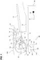
- FIG. 1 is an illustration of a structure of an image reading apparatus including a sheet feeding apparatus according to a first embodiment of the present invention.
- an image reading apparatus 100 includes an image reading apparatus main body 100A.
- the image reading apparatus main body 100A includes a first image reading unit 150 which reads an image on a front surface (first face) of an original document, which may be a sheet.
- the image reading apparatus 100 also includes an automatic document feeder (ADF) 100B.
- the automatic document feeder 100B is a sheet feeding apparatus which feeds an original document, such as a sheet, and includes a second image reading unit 103 which reads an image on a rear surface (second face) of an original document.
- the first image reading unit 150 includes a transparent surface glass member 151 on which an original document conveyed by the automatic document feeder 100B passes during in-flow reading of the document, and a white reading roller 107 arranged to face a reading position.
- in-flow reading is that the document to be read is provided to the sheet-feeding apparatus 100 in such a way that it is fed past the sheet-reading units, rather than being placed, for example, face-down on a platen above a sheet-reading unit, and having to be placed and removed by hand.
- the first image reading unit 150 also includes a first mirror unit 159 which includes a lamp 153 and a mirror 154 and which irradiates an original document passing on the surface glass member 151 with light to enable the reading of the original document image.
- the first image reading unit 150 also includes a second mirror unit 159a which includes two mirrors 155 and 156.
- the first image reading unit 150 also includes a lens 157 and a CCD (charge-coupled device sensor) 158.
- the first image reading unit 150 irradiates a front surface of an original document passing on the surface glass member 150 with light from the lamp 153 and the light reflected by the original document is guided to the lens 157 via the mirrors 154 to 156.
- the lens 157 forms an image of the original document at a light receiving unit of the CCD 158.
- a glass (or similar) base plate 152 is arranged on an upper surface of the image reading apparatus main body 100A.
- “fixed” reading in which an original document image is placed on the base plate 152, the original document image is read while moving the first and second mirror units 159 and 159a.
- the original document is set on the glass base plate by the automatic document feeder 100B or manually.
- the first and second mirror units 159 and 159a are moved in a direction parallel to the original base plate glass 152 while irradiating a lower surface of the original document with the lamp 153 by rotary drive of a drive motor (not illustrated).
- a white reference member 160 which is a white reference for the first image reading unit 150 is arranged between the base plate glass 152 and the surface glass member 151.
- the first image reading unit 150 reads the surface of the white reference member 160 to generate white-level reference data, and detects a change in shade of image signals relative to the generated reference data.
- the second image reading unit 103 which reads an image on a rear surface of an original document includes a contact image sensor 103a which is an image reading unit integrally constituting a lamp, a lens, and a CCD (which are not illustrated).
- the second image reading unit 103 also includes a rear surface glass 103b, and a white rear surface reading roller 109 arranged to face the contact image sensor 103a at a reading position of the contact image sensor 103a.
- the automatic document feeder 100B is adapted to convey original documents (not illustrated) stacked on (i.e. held in) an original document accommodating unit 101, which is a sheet accommodating unit, to the first image reading unit 150 and the second image reading unit 103 during in-flow reading, and includes a pickup roller 51 which is arranged above the original document accommodating unit 101 and which is adapted to feed out an original document from the original document accommodating unit 101.
- the pickup roller 51 which acts as a sheet feeding unit, is rotatably held on a pivoting end of an arm 54 which is itself vertically pivotable toward and away from the original document accommodating unit 101.
- the pickup roller 51 is usually retracted to an upper position, which is a home position, by upward turning of the arm 54 so as not to interfere with the operation of setting an original document.
- the pickup roller 51 lowers by downward turning of the arm 54 and abuts an upper surface of an original document in the original document accommodating unit 101.
- a pair of separating rollers 52, 53 is arranged downstream of the pickup roller 51. "Downstream" is used with reference to the feeding direction of the original document that is fed from the original document accommodating unit 101.
- the pair of separating rollers 52, 53 constitutes a conveying roller 52 and a separating roller 53 and is adapted to separate original documents one by one.
- two pairs of conveying rollers 104 and a pair of registration rollers 105 are arranged downstream of the pair of separating rollers 52, 53.
- the pairs of conveying rollers 104 convey an original document separated one by one by the pair of separating rollers 52, 53, and the pair of registration rollers 105 aligns the leading edge of the original document conveyed by the pairs of conveying rollers 104.
- the leading edge of the original document is aligned by causing the leading edge of the original document conveyed by the pairs of conveying rollers 104 to hit a nip portion of the pair of registration rollers 105 in a rest state to form a loop.
- the arm 54 is first lowered until the pickup roller 51 abuts a top surface of the original documents, and the pickup roller 51 is then rotated to convey the original document at the top to the pair of separating rollers 52, 53. If a plurality of sheets of the original documents are conveyed in an overlapping manner, the pair of separating rollers 52, 53 separates an original document at the top from other documents and conveys the separated document.
- the single original document thus-separated is conveyed by the pairs of conveying rollers 104 to the pair of registration rollers 105.
- the original document After the leading edge of the original document is aligned by the pair of registration rollers 105, the original document is guided by the pair of registration rollers 105, a feed-out roller 106 and the reading roller 107 to the first image reading unit 150, and passes onto the surface glass member 151. At this time, (a CCD 158 of) the first image reading unit 150 reads image information on the front surface (i.e. the first face) of the original document.
- the original document is conveyed to the second image reading unit 103 by an intermediate conveying roller 108 and the rear surface reading roller 109. While the original document passes the rear surface glass 103b, the contact image sensor 103a reads image information on the rear surface (i.e. the second face) of the original document. After the reading of the image on the rear surface of the original document by the contact image sensor 103a is completed, the original document is discharged on a discharge tray 112 by a pair of discharge rollers 111. The discharge tray 112 is arranged below the original document accommodating unit 101.
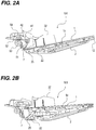
- FIGS. 2A and 2B are sectional views illustrating the structure of the original document accommodating unit 101.
- the original document accommodating unit 101 accommodates original documents which are inserted along the original document feeding direction (also known as the sheet feeding direction).
- the original document accommodating unit 101 includes a placing plate 1, which is a placing member having an original document placing surface 1a and which is capable of being lifted and lowered by a lifting/lowering mechanism, and a base plate 2, which supports the placing plate 1 so that the placing plate 1 can be lifted and lowered.
- Original documents are inserted and set along the original document placing surface 1a of the placing plate 1 in the original document feeding direction by a user.
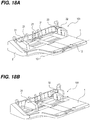
- FIGS. 18A and 18B are perspective views illustrating the structure around the original document accommodating unit 101.
- a pair of side edge restricting plates 31, 32 which restrict both edges of the original documents in the width direction perpendicular to (intersecting with) the original document feeding direction, are attached to the original document accommodating unit 101.
- the pair of side edge restricting plates 31, 32 are slidably attached in the width direction of the original documents and may slide in a lateral direction shown by arrows in FIG. 18B . If the original documents are placed over an allowable maximum stacking amount, the sheets are not conveyed stably by the pickup roller 51. Accordingly, a rib 33 which restricts the sheet stacking amount is formed on each of the pair of side edge restricting plates 31, 32 so that the sheets are not placed on the placing plate 1 over the allowable stacking amount.
- FIGS. 2A and 2B One side edge restricting plate 32 is illustrated in FIGS. 2A and 2B .
- the placing plate 1 is joined with the base plate 2 by a pivoting shaft 12 at an arbitrary position, which is a position along the base plate other than the leading end (in the document feeding direction) of the placing plate 1.
- the pivoting shaft enables the lifting and lowering about the shaft of the placing plate 1.
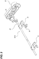
- the placing plate 1 is lifted and lowered by a lifting and lowering mechanism 101A illustrated in FIG. 3 , which is arranged below the placing plate 1 in the present embodiment.
- the lifting and lowering mechanism 101A includes a pushing-up member 22, which pushes the placing plate 1 up from below, a placing plate drive source 23 such as a pulse motor, and a drive transmission unit 24, to which the pushing-up member 22 is secured via a rotating shaft 25 and which transmits the rotary drive of the placing plate drive source 23 to a rotating shaft 25.
- the placing plate 1 is lifted and lowered as the pushing-up member 22 is rotated integrally with the rotating shaft 25 by means of the placing plate drive source 23 and the drive transmission unit 24 which transmits rotary drive to the pushing-up member 22.
- a set position detection sensor 26 illustrated in FIG. 3 detects that the placing plate 1 has reached a set position, which is the lowermost position, by the operation of the lifting and lowering mechanism 101A.
- a transmission-type, original document, detection sensor 132 which is a detection unit configured to detect whether original documents are placed on the placing plate 1, is attached below the placing plate 1. Further, a flag 13 is attached to the placing plate 1 so that the flag 13 can rock (i.e. rotate) about a rocking shaft 13c as a support point.
- the original document, detection sensor 132 and the flag 13 are arranged at the downstream end portion of the original document placing surface 1a in the original document feeding direction. The original document, detection sensor 132 and the flag 13 detect whether sheets are placed on the placing plate 1 on a downstream end portion in the original document feeding direction of the placing plate 1.
- the flag 13 includes a pressing portion 13a, which is pressed by original documents when the original documents are placed on the placing plate 1, and a light shielding portion 13b, which blocks light to the original document set detection sensor 132.
- the pressing portion 13a of the flag 13 protrudes on the upper surface of the placing plate by means of a biasing unit (not illustrated) until original documents are placed on the placing plate 1.
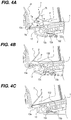
- the pressing portion 13a is pressed by the original documents whereby the flag 13 rocks in the counterclockwise direction as seen in FIGS. 4A, 4B and 4C .
- the light shielding portion 13b brings the original document set detection sensor 132 into a light-shielded state. Accordingly, the original document set detection sensor 132 can detect that the original documents are placed on the placing plate 1.
- the flag 13 rocks in the clockwise direction by the biasing unit (not illustrated) so that the pressing portion 13a protrudes on the upper surface of the placing plate.
- the light shielding portion 13b moves away from the original document set detection sensor 132 and the original document set detection sensor 132 is released from the light-shielded state. Accordingly, the original document set detection sensor 132 can detect that no original document remains on the placing plate 1.
- the time for determining that no original document remains may not be sufficient. Accordingly, if the detection of the last original document is delayed, such a situation that the original document feeding operation continues after the last original document on the placing plate is fed may occur. Therefore, the time for determining that no original document remains after starting feeding of the last sheet is preferably shortened to shorten the feeding interval of the original documents.
- the presence or absence of the original documents is detected by the turning of the flag at the original document tray, it will take much time to determine that no original document remains when the rotating distance of the flag from the state where the flag is pressed by the placed original documents until the detection sensor detects that no original document remains is large.
- the flag 13 protrudes by a small amount on the placing surface of the placing plate 1 to make the rotating distance of the flag to a detection position smaller so as to detect that no original document remains on the placing plate 1 (hereinafter referred to as the last sheet detection) in a short time.
- FIG. 5 is a control block diagram of the image reading apparatus 100.
- a CPU controller 400 includes a CPU 401 and controls an automatic document feeder controller 101C, a read controller 201, an image signal controller 405, and an image forming controller 301 according to control programs stored in a ROM 402 and settings of an operation portion 200.
- the CPU controller 400 also controls the placing plate drive source 23 and a notifying unit 133.
- the automatic document feeder controller 101C controls the automatic document feeder (ADF) 100B shown in FIG. 1 and the read controller 201 controls a light source power supply 202 which turns on the lamp 153 of the first image reading unit 150.
- ADF automatic document feeder
- the operation portion 200 includes a plurality of keys for setting various functions relating to image formation (such as 1- or 2-sided printing, collated pages or not, etc.), and a display portion which displays the setting state.
- the operation portion 200 outputs key signals corresponding to respective keys operated by a user to the CPU controller 400 and displays corresponding information on the display portion based on signals from the CPU controller 400.
- a RAM 403 is utilized as an area for temporarily storing control data and as a work area for arithmetic operation associated with the control.
- An external interface (I/F) 406 is an interface between the image reading apparatus 100 and an external computer 407, and is configured to convert print data from the external computer 407 to a bitmap image and output the bitmap image as image data to the image signal controller 405.
- the image forming controller 301 outputs the image data from the image signal controller 202 to the image forming unit of the image forming apparatus (not illustrated).
- the original document, detection sensor 132, the set position detection sensor 26 and the original document surface detection sensor 41 described above are also connected to the CPU controller 400.
- the CPU controller 400 controls the lifting and lowering operations and the original document feeding operation of the placing plate 1 of the automatic document feeder 100B according to signals from the respective sensors. Next, control of an original document conveying operation of the automatic document feeder 100B will be described with reference to a flowchart illustrated in FIG. 6 .
- the CPU controller 400 activates the notifying unit 133 such as a lamp or a sound source (S402) to inform a user of the detection.
- the original document set detection sensor 132 moves to stand-by mode, when the original document set detection sensor 132 does not detect the original documents (N in s401).
- the activation of the notifying unit 133 allows a copy starting instruction or a scanning starting instruction by a user to be in an effective state, and then the CPU controller 400 is waiting for those instructions (N in S403).
- the driving by the placing plate drive source 23 is started (S404) and the lifting operation of the placing plate 1 is started.
- the lifting operation of the placing plate 1 continues until the pickup roller 51 which has moved to the lowermost position is pushed up by the top surface of the placed original documents and the flag 42 of the arm 54 - lifted with the pushing up of the pickup roller 51 - blocks the original document surface detection sensor 41.
- the feeding position a position where the original documents can be fed.
- the placing plate 1 is lifted to the uppermost position as illustrated in FIG. 2B when one sheet of the original document is placed, for example.
- the control of original document feeding terminates (S409).
- the driving by the placing plate drive source 23 is started (S410) to start the lowering operation of the placing plate 1.
- the lowering operation of the placing plate 1 continues until the set position detection sensor 26 detects the lower limit position of the pushing-up member 22 under the placing plate (N in S411).
- the driving of the placing plate drive source 23 is terminated (S412). Thereafter, the control is in a standby mode until next original documents are set.
- a controller may be provided that, when connected to the sheet feeding apparatus, causes the sheet feeding apparatus to perform the method as illustrated in FIG. 6 and as described above.
- the controller may be a part of the sheet feeding apparatus or part of the image reading apparatus, or may even be an external controller in a computer, for instance.
- the controller may control the standby state that the sheet feeding apparatus enters if the detection sensor does not detect an original document (N in S401) or if no conveyance starting instruction is input (N in S403).
- the controller may further control the feedback mechanisms in steps S405, S408 and S411 of FIG.
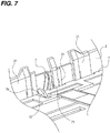
- a curl suppressing member 7, which suppresses curl of original documents placed on the placing plate 1, is arranged above the original document placing surface of the placing plate 1 as illustrated in FIG. 7 in a manner that the curl suppressing member 7 is in an inclined state in which a downstream end thereof in the original document feeding direction (a downstream side thereof in the sheet feeding direction) is lower than an upstream end.
- the curl suppressing member 7, which is a pressing member adapted to press the sheets is formed from a bent wire, for example, and has an abutment portion 71 that abuts leading edges of the original documents accommodated along the sheet feeding direction, and pivot portions 74 which are a pivoting center.
- the pivot portions 74 formed at one end of the curl suppressing member 7 are elastically latched to a pivoting supporting member 73, illustrated in FIG. 8A , which is itself attached to an inner side of an abutting portion 21 of the base plate 2. This allows the curl suppressing member 7 to be pivotably supported to the base plate 2.
- the curl suppressing member 7 can be positioned in a pressing position (suppressing position), as illustrated in FIG. 9A which will be described below, at which the curl suppressing member 7 presses the sheets to suppress upward curl of the leading edges of the set original documents.
- the curl suppressing member 7 is in the inclined state at the suppressing position.
- the curl suppressing member 7 can also be retracted from the original document conveying surface to be positioned at a separated position (retracting position), as illustrated in FIG. 9C which will be described below, away from the sheets when the original documents are fed.
- the suppressing position of the curl suppressing member 7 is a position at which the abutment portion 71 is inclined to the upper surface of the placing plate 1 at an angle of 45 to 55 degrees, as illustrated in FIGS.
- the suppressing position is determined by abutment between the curl suppressing member 7 and the placing plate 1 in a state where the pivot portions 74 of the curl suppressing member 7 are positioned lower than the upper surface of the placing plate 1 and in the inner side of the abutting portion 21 of the base plate 2.
- the suppressing position is determined by the abutment of the curl suppressing member 7 and the pivoting supporting member 73 in a predefined orientation.
- the abutment portion 71 of the curl suppressing member 7 has a suppressing portion 7a which protrudes above the placing plate 1 to suppress upward curl of the original documents entering between the curl suppressing member 7 and the placing plate 1 when the curl suppressing member 7 is at the suppressing position as illustrated in FIG. 9A , for example.
- the suppressing portion 7a which is a pressing portion, is in the inclined state so as to be closer to the original document placing surface 1a at downstream side in the original document feeding direction than at the upstream side.
- the suppressing portion 7a in the inclined state is adapted to press the leading edges of the original documents placed on the placing plate 1.
- the curl suppressing member 7 guides the downstream edges in the original document feeding direction of the original documents inserted in the sheet feeding direction along the original document placing surface 1a toward the original document placing surface 1a (toward the flag 13) and presses the downstream edges of the original documents set on the placing plate 1 in the sheet feeding direction toward the original document placing surface 1a.
- the abutment portion 71 of the curl suppressing member 7 also includes a restricting portion 7b which extends upward from the suppressing portion 7a and which is adapted to restrict accommodation of original documents with a particularly large curl that cannot be suppressed by the suppressing portion 7a into the placing plate 1.
- the curl suppressing member 7 is prevented from obstructing the lowering operation of the placing plate 1, and original documents with upward curl or fold which cannot be ensured to be appropriately handled by the pair of separating rollers are prevented from being set (i.e. inserted in a correct feeding position), as will be described below.
- the original documents When original documents are set on the placing plate 1 to which the curl suppressing member 7 is attached, the original documents are placed in a manner that the leading edges thereof abut the abutting surface 21 of the base plate 2 if the leading edges of the original documents are not curling or folded or if the leading edges curl or are folded downward.
- the original documents are inserted ahead until the leading edges thereof abut the abutting surface 21 while curl or the like of the leading edges is suppressed along the inclined restricting portion 7a of the curl suppressing member 7 represented by a height hr as illustrated in FIG. 4A described above if the leading edges of the original document curl or are folded upward.
- the original documents are set on the placing plate in a state where the upward curl or fold of the leading edge portion (the downstream edge portion in the sheet feeding direction) is suppressed (corrected).
- the original documents can be set on the placing plate in a state where the curl or fold is suppressed. Further, by suppressing the upward curl or fold of the leading edges in this manner, the placement of original documents can be accurately detected by means of the flag 13 and the original document set detection sensor 132. For example, if the curl suppressing member 7 is not provided, the flag 13 cannot be pressed down when original documents having leading edges curling or folded upward are set so that the leading edges abut the abutting portion 21 due to the curl or the like of the leading edges. As a result, the setting of the original documents may not be detected.
- corner portions of leading edges of original documents are ensured to be brought into contact with the suppressing portion 7a when the original documents are placed on the placing plate 1 since the suppressing portion 7a of the curl suppressing member 7 is inclined in a manner that the downstream side thereof in the sheet feeding direction is lower. Consequently, the upwardly curling leading edge portions of the original documents can be ensured to be pressed by the curl suppressing member 7.
- the upward curl or fold of the leading edges of the original documents can be suppressed and the flag 13 can be rotated by the original documents P as illustrated in FIG. 4B .
- the detection sensor 132 can detect the setting of original documents.
- the curl suppressing member 7 can press the large upward curl of the leading edges of the original documents when such original documents are being placed on the placing plate 1 so as to prevent turning up of the curl.
- the detection sensor 132 does not detect the setting of the original documents and thus does not output the detection signal to the CPU controller 400 in this case.
- the shape of the curl suppressing member 7 satisfies hT > hr, so that only original documents having the amount of curl or fold at which the pair of separating rollers 52, 53 can ensure to convey the original documents can be set on the placing plate 1. Accordingly, a jam can be prevented from being caused.
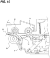
- the retracting position is a position at which a top end of the curl suppressing member 7 is lower than the top surface of original documents, that is, a position to which the top end of the curl suppressing member 7 is retracted from a conveyance path shown by a dashed and a dotted line 55 in FIG. 10 through which the original documents are fed by the pickup roller 51 and further conveyed while being separated by the pair of separating rollers 52, 53.
- the curl suppressing member 7 is prevented from obstructing the feeding operation.
- FIG. 10 illustrates the feeding position when one sheet of original document is placed. However, the height of the top surface of original documents at the feeding position does not change even when more than one sheet of original documents is placed.
- the curl suppressing member 7 When the curl suppressing member 7 is moved to the retracting position, the curl suppressing member 7 is in a state abutting a projection 1a (see FIGS. 9B and 9C ) under the placing plate, so that the curl suppressing member 7 is fixed at a position at which the curl suppressing member 7 does not protrude on the original document conveying surface. Furthermore, in the present embodiment, the curl suppressing member 7 never presses the upper surface (printed surface) of the placed original document while moving all the way from the suppressing position illustrated in FIG. 9A to the retracting position illustrated in FIG. 9C . This decreases the likelihood of damaging the surface of an original document due to inserting and removing of the original document during a feeding operation or lifting of the placing plate. In addition, since the curl suppressing member 7 does not come into contact with the surface of a sheet being fed, skew feeding of sheets and feeding failure caused by the curl suppressing member 7 pressing on the sheets are less likely to occur during sheet feeding.
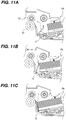
- the curl suppressing member 7 With the structure of the curl suppressing member 7, the curl suppressing member 7 is pressed by the leading edge in the original document feeding direction of an original document bundle (sheet bundle) PA to be moved to the retracting position even when the original document bundle PA of the predetermined number of sheets or more are set as illustrated in FIGS. 11A to 11C .
- the space of the original document placing portion is not narrowed. Accordingly, even an original document bundle of a large number of sheets can be set without trouble.
- the curl suppressing member 7 is arranged at a position where the curl suppressing member 7 abuts a central portion of an original document of the smallest size (smallest sheet) having the narrowest width among the original documents accommodated in the original document accommodating unit 101. Accordingly, the operation of restricting side edges of original documents can be performed without damaging a side of the original document bundle even when the original document bundle is set while the side edge restricting plate is open and then the side edge restricting plate is caused to slide in the restricting direction of the original document width.
- the curl suppressing member 7 does not operate to press the leading edges of original documents from above.
- the rigidity of the original document bundle as a whole is high and the self-weight of the original document bundle acts thereon. Accordingly, the leading edges of the original documents will not be separated from the placing surface of the placing plate 1. Therefore, false detection by the original document set detection sensor 132 due to separation of the leading edges of the original documents from the placing surface of the placing plate 1 does not occur.
- the curl suppressing member 7 also moves from the retracting position to the suppressing position as illustrated in FIGS. 9C to 9A in this order with the lowering operation.
- the placing plate 1 can move smoothly without being caught by the curl suppressing member 7 while the abutting portions of the placing plate 1 and the curl suppressing member 7 are being slid because the curl suppressing portion 7 is bent in the original document feeding direction.
- the curl suppressing member 7 also moves from the retracting position to the suppressing position as illustrated in FIGS. 11C to 11A in this order when an original document bundle of a large number of sheets is removed.
- the pivoting supporting member 73 includes a pair of supporting portions 73a which have a substantially cylindrical shape and pivotably support the pivot portions 74 formed at both ends of the curl suppressing member 7.
- Side surfaces 73b of the pair of supporting portions 73a are in a tapered shape and face each other and abut the pivot portions 74 at both sides of one end of the curl suppressing member 7.
- the force is applied to the side faces 73b facing each other of the pair of supporting portions 73a, and accordingly, a force in a direction opposite to the direction r shown in FIG. 8 to return the curl suppressing member 7 to the suppressing position is generated in the curl suppressing member 7. Accordingly, as the placing plate 1 is lowered, the abutting position of the placing plate 1 and the curl suppressing member 7 moves lower and the curl suppressing member 7 returns to the suppressing position due to the action of the force. With such a structure, the curl suppressing member 7 can be ensured to be moved between the suppressing position and the retracting position without any special drive source needing to be provided.
- the curl suppressing member 7 is formed by bending a wire so that the sheets are not damaged by the load of the curl suppressing member 7.
- the material and the shape of the curl suppressing member 7 are not limited thereto and may be made in any shape and with any material that enables the invention to be performed.
- the curl suppressing member 7 is preferably lightweight so as not to damage the original documents and so as not to inhibit the raising of the placing plate.
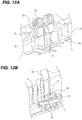
- FIGS. 12A and 12B illustrate a part of an original document tray of an automatic document feeder according to the present embodiment.
- a curl suppressing member 75 can move between a retracting position illustrated with a solid line and a suppressing position illustrated with a broken line.
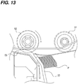
- Pre-separation plates 22 which constitute a separating portion are arranged on an inclined surface of the abutting portion 21. By providing the pre-separation plates 22, original documents can be loosened or separated when the original documents are fed by the pickup roller 51 and then conveyed to the pair of separating rollers 52, 53, as illustrated in FIG. 13 .
- the curl suppressing member 75 rotates around a pivot shaft 78 and has a pivoting portion 74 (such as a sleeve) formed along the pivot shaft 78, as illustrated in FIG. 12B .
- the pivoting portion 74 is attached to a pivoting supporting portion 76 attached to the base plate 2 so that the curl suppressing member 75 is pivotably attached to the base plate 2.
- a torsion spring 77 is attached to the circumference of the pivoting portion 74 so that the curl suppressing member 75 is normally held at (e.g. by being biased toward) the suppressing position by the torsion spring 77.
- the curl suppressing member 75 is a flat plate member formed of ABS (acrylonitrile-butadiene-styrene) or PC/ABS (Polycarbonate/acrylonitrile-butadiene-styrene).
- the retracting position of the curl suppressing member 75 is set so that the pre-separation plates 22 exert a pre-separation effect when the curl suppressing member 75 is moved to the retracting position.
- the curl suppressing member 75 serves as the pre-separation plate at the retracting position.
- the curl suppressing member 75 - which has both the first function of restricting curling or folding in leading edges of original documents to stabilize the leading edge position during feeding and the second function of pre-separating so as to increase the separating performance - can be obtained with a simple structure.
- the material and the shape of the curl suppressing member 75 are not limited to those in the present embodiment, but can be any material and shape that would be suitable for these two functions.
- FIGS. 14A and 14B illustrate a portion of an original document tray of an automatic document feeder according to the comparative example.
- the components which are the same as those in FIGS. 2A, 2B and 7 are represented by the same reference numerals.
- a curl suppressing member 75A can move between a retracted position illustrated with a solid line and a suppressing position illustrated with a broken line in FIG. 14A .
- a torque limiter 783 is attached to a drive shaft 513 of the pickup roller 51.
- the curl suppressing member 75A is also attached to the drive shaft and is provided with a one-way clutch 763 at an inner diameter side of the sleeve or hook that attaches it to the drive shaft.
- the one-way clutch 763 is attached to the drive shaft coaxially with the torque limiter 783 attached to the drive shaft 513.
- the curl suppressing member 75A rotates in the same direction as the pickup roller 51 when the pickup roller 51 rotates, and idles when a force in the direction opposite to the rotating direction of the pickup roller 51 is applied thereto, due to the action of the one-way clutch 763.
- a torsion spring 773 is attached to the outer housing of the torque limiter 783.
- the torsion spring 773 is a biasing member which applies a force to the curl suppressing member 75A toward the suppressing position.
- the inner ring side of the torque limiter 783 drives substantially equally to the drive shaft 513 via a fixing pin 793 press-fitted on the drive shaft 513 of the pickup roller.
- the torsion spring 773 applies a maximum torque TSMAX - that is, a torque TSMAX to return to the suppressing position - to the curl suppressing member 75A at the retracted position, and applies a minimum torque TSMIN to the curl suppressing member 75A at the suppressing position.
- a threshold TL of torque interruption by the torque limiter 783 is set to be larger than the torque TSMAX of the torsion spring at the retracting position and smaller than a torque TU applied by the placing plate 1 via the curl suppressing member 75A while the placing plate is lifted.
- FIGS. 15A to 15C illustrate movement of the curl suppressing member 75A from the suppressing position to the retracted position with the lifting operation of the placing plate 1 in the comparative example.
- the curl suppressing member 75A is not completely moved to the retracting position but reaches near the retracted position (near the separated position) at this time as illustrated in FIG. 15C .
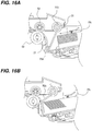
- FIGS. 16A and 16B illustrate retraction of the curl suppressing member 75A when an original document bundle PA of a large number of sheets are placed on the placing plate 1 at the set position.
- the curl suppressing member 75A moves to the retracting position by being pressed by the leading edge of the original document bundle.
- the curl suppressing member 75A does not move completely to the retracted position even when the leading edge of the original document bundle PA abuts the abutting portion 21, as illustrated in FIG. 16B .
- the curl suppressing member 75A moves completely to the retracting position when the pickup roller 51 rotates, that is, when the original document feeding operation (sheet feeding operation) is started.
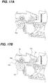
- FIG. 17A illustrates a state similar to that of FIG. 15C where the placing plate 1 is moved to the feeding position.
- the leading edges of the original documents are restricted by the curl suppressing member 75A until the feeding operation is started.
- the curl suppressing member 75A rotates in the same direction as the pickup roller 51 by the action of the one-way clutch 763.
- the curl suppressing member 75A is retracted completely from the original document conveying surface 553 constituted by the pickup roller 51 and the pair of separating rollers 52, 53.
- the torsion spring 773 applies the torque TSMAX to return to the suppressing position as shown by a broken-line arrow in FIG. 17A to the curl suppressing member 75A.
- the torque TL in the direction opposite to that of the broken-line arrow, which is transmitted from the drive shaft 513 of the pickup roller via the torque limiter 783, is set to be larger than the torque TSMAX, as described above. Accordingly, the curl suppressing member 75A is kept in a biased state at the retracted position by the torque TL even when the feeding operation by the pickup roller 51 continues. Subsequently, when the feeding operation ends, the pickup roller 51 stops and torque is not transmitted from the shaft 513 of the pickup roller any longer. Accordingly, the curl suppressing member 75A returns to the position of FIG. 17A due to the torque of the torsion spring 773. Then, the curl suppressing member 75A returns to the suppressing position as illustrated in FIGS. 15C to 15A (in that order) with the lowering operation of the placing plate 1.
- the function of restricting curling or folded leading edges of original documents to stabilize the leading edge position during feeding can be obtained with a simple structure, similarly to the first and second embodiments described above. Further, in the comparative example, since the leading edges of the original documents can be restricted until immediately before starting of the feeding operation, the leading edge position in feeding can be stabilized more securely.
- the description presented so far is made on the automatic document feeder 100B which feeds original documents to the image reading units 103 and 150.
- the embodiments can obviously be applied to a sheet feeding apparatus which is arranged in an image forming apparatus and adapted to feed sheets to an image forming unit.
Landscapes
- Engineering & Computer Science (AREA)
- Multimedia (AREA)
- Signal Processing (AREA)
- Physics & Mathematics (AREA)
- General Physics & Mathematics (AREA)
- Sheets, Magazines, And Separation Thereof (AREA)
- Controlling Sheets Or Webs (AREA)
Applications Claiming Priority (1)
| Application Number | Priority Date | Filing Date | Title |
|---|---|---|---|
| JP2009205686A JP5495681B2 (ja) | 2009-09-07 | 2009-09-07 | シート給送装置、画像読取装置及び画像形成装置 |
Publications (2)
| Publication Number | Publication Date |
|---|---|
| EP2293150A1 EP2293150A1 (en) | 2011-03-09 |
| EP2293150B1 true EP2293150B1 (en) | 2020-05-13 |
Family
ID=43259848
Family Applications (1)
| Application Number | Title | Priority Date | Filing Date |
|---|---|---|---|
| EP10175261.6A Active EP2293150B1 (en) | 2009-09-07 | 2010-09-03 | Sheet feeding apparatus and image reading apparatus |
Country Status (5)
| Country | Link |
|---|---|
| US (1) | US8393614B2 (zh) |
| EP (1) | EP2293150B1 (zh) |
| JP (1) | JP5495681B2 (zh) |
| KR (1) | KR101311608B1 (zh) |
| CN (1) | CN102009864B (zh) |
Families Citing this family (16)
| Publication number | Priority date | Publication date | Assignee | Title |
|---|---|---|---|---|
| JP5768505B2 (ja) * | 2011-05-31 | 2015-08-26 | 富士ゼロックス株式会社 | 用紙供給装置及びこれを用いる画像形成装置 |
| KR101850276B1 (ko) * | 2012-01-03 | 2018-04-19 | 에스프린팅솔루션 주식회사 | 급지장치 및 이를 포함하는 화상형성장치 |
| JP5942491B2 (ja) * | 2012-03-07 | 2016-06-29 | 株式会社リコー | 自動原稿給紙装置、画像読み取り装置及び画像形成システム |
| JP6000681B2 (ja) | 2012-06-22 | 2016-10-05 | キヤノン株式会社 | シート搬送装置 |
| KR102047904B1 (ko) * | 2013-09-26 | 2019-11-22 | 휴렛-팩커드 디벨롭먼트 컴퍼니, 엘.피. | 인쇄매체공급장치 및 이를 갖는 화상형성장치 |
| DE102013020895A1 (de) * | 2013-12-11 | 2015-06-11 | Giesecke & Devrient Gmbh | Eingabemodul und Verfahren zum Zuführen von Wertdokumenten zu einer Wertdokumentbearbeitungsvorrichtung sowie System zur Bearbeitung von Wertdokumenten |
| JP6676304B2 (ja) * | 2015-07-31 | 2020-04-08 | キヤノン株式会社 | 回転体ユニット、シート搬送装置及び画像形成装置 |
| US11046097B2 (en) * | 2015-10-28 | 2021-06-29 | Hewlett-Packard Development Company, L.P. | Media retraction |
| JP6739948B2 (ja) * | 2016-03-01 | 2020-08-12 | キヤノン株式会社 | 画像処理装置、その制御方法及びコンピュータプログラム |
| WO2018048391A1 (en) * | 2016-09-07 | 2018-03-15 | Hewlett-Packard Development Company, L.P. | Pick arm raise with one-way clutch and torque limiter |
| JP7113653B2 (ja) * | 2018-04-17 | 2022-08-05 | シャープ株式会社 | 原稿読取装置及び原稿読取方法 |
| CN108726216A (zh) * | 2018-07-27 | 2018-11-02 | 新会江裕信息产业有限公司 | 一种喷墨打印机的下进纸系统 |
| JP7297452B2 (ja) | 2019-01-18 | 2023-06-26 | キヤノン株式会社 | シート給送装置、画像読取装置、画像形成装置 |
| JP7255204B2 (ja) * | 2019-01-30 | 2023-04-11 | ブラザー工業株式会社 | 画像読取装置 |
| JP7433866B2 (ja) | 2019-11-28 | 2024-02-20 | キヤノン株式会社 | シート搬送装置及び画像読取装置 |
| JP2022178377A (ja) * | 2021-05-20 | 2022-12-02 | セイコーエプソン株式会社 | 画像読取装置、記録装置 |
Family Cites Families (23)
| Publication number | Priority date | Publication date | Assignee | Title |
|---|---|---|---|---|
| US3957366A (en) * | 1974-09-05 | 1976-05-18 | Xerox Corporation | Sheet feeding apparatus |
| JPS63202523A (ja) * | 1987-02-13 | 1988-08-22 | Minolta Camera Co Ltd | 給紙装置 |
| US4952177A (en) * | 1989-12-19 | 1990-08-28 | Minnesota Mining And Manufacturing Company | Clamp for electro-surgical dispersive electrode |
| JPH07196186A (ja) * | 1993-12-29 | 1995-08-01 | Canon Inc | シート材給送装置 |
| CH689671A5 (fr) * | 1994-03-07 | 1999-08-13 | Ocd Sa | Dispositif d'introduction de feuilles ou d'enveloppes à imprimer. |
| DE69517251T2 (de) * | 1994-07-29 | 2000-11-23 | Canon Kk | Apparat zum Zuführen von Bögen |
| US5887867A (en) * | 1995-02-15 | 1999-03-30 | Canon Kabushiki Kaisha | Sheet supplying apparatus including first and second sheet supply rollers and a separation roller all made of the same material |
| JPH11199078A (ja) * | 1998-01-16 | 1999-07-27 | Matsushita Denso System Kk | 給紙装置 |
| US6199855B1 (en) * | 1998-03-31 | 2001-03-13 | Samsung Electronics Co., Ltd. | Paper feeding apparatus for office automation system |
| TW500666B (en) * | 2000-03-03 | 2002-09-01 | Benq Corp | Paper feeding system with paper separation mechanism and paper stop mechanism |
| US6877738B2 (en) | 2001-05-10 | 2005-04-12 | Canon Kabushiki Kaisha | Sheet material feed apparatus and recording apparatus |
| JP3824909B2 (ja) * | 2001-11-09 | 2006-09-20 | 株式会社リコー | 給紙装置およびシート搬送装置 |
| JP3913120B2 (ja) * | 2002-06-18 | 2007-05-09 | キヤノン株式会社 | シート材給送装置及び記録装置 |
| JP4026008B2 (ja) * | 2003-07-25 | 2007-12-26 | セイコーエプソン株式会社 | 被記録媒体戻し装置、被記録媒体給送装置、記録装置および被噴射媒体給送装置 |
| US7100914B2 (en) * | 2004-01-15 | 2006-09-05 | Hewlett-Packard Development Company, L.P. | Sheet media input |
| JP4284654B2 (ja) | 2004-03-23 | 2009-06-24 | 村田機械株式会社 | 画像読取装置 |
| JP3960322B2 (ja) * | 2004-06-25 | 2007-08-15 | ブラザー工業株式会社 | 被記録シート供給装置及びファクシミリ装置 |
| JP4710430B2 (ja) * | 2005-06-21 | 2011-06-29 | 富士ゼロックス株式会社 | シート供給装置及び画像形成装置 |
| JP2007290794A (ja) * | 2006-04-21 | 2007-11-08 | Noritsu Koki Co Ltd | シート搬送装置 |
| JP4907460B2 (ja) * | 2007-08-02 | 2012-03-28 | 株式会社リコー | 自動原稿搬送装置および画像形成装置 |
| JP5132368B2 (ja) * | 2008-03-07 | 2013-01-30 | キヤノン株式会社 | 画像読取装置及び画像形成装置 |
| JP2010030768A (ja) * | 2008-07-30 | 2010-02-12 | Seiko Epson Corp | 給送装置及び記録装置 |
| TWI422493B (zh) * | 2011-03-25 | 2014-01-11 | Primax Electronics Ltd | 擋紙結構 |
-
2009
- 2009-09-07 JP JP2009205686A patent/JP5495681B2/ja active Active
-
2010
- 2010-08-31 US US12/872,343 patent/US8393614B2/en active Active
- 2010-09-03 EP EP10175261.6A patent/EP2293150B1/en active Active
- 2010-09-06 KR KR1020100086895A patent/KR101311608B1/ko active IP Right Grant
- 2010-09-07 CN CN2010102776254A patent/CN102009864B/zh active Active
Non-Patent Citations (1)
| Title |
|---|
| None * |
Also Published As
| Publication number | Publication date |
|---|---|
| KR20110026393A (ko) | 2011-03-15 |
| EP2293150A1 (en) | 2011-03-09 |
| JP5495681B2 (ja) | 2014-05-21 |
| JP2011057304A (ja) | 2011-03-24 |
| US8393614B2 (en) | 2013-03-12 |
| CN102009864B (zh) | 2013-10-16 |
| KR101311608B1 (ko) | 2013-09-26 |
| CN102009864A (zh) | 2011-04-13 |
| US20110058881A1 (en) | 2011-03-10 |
Similar Documents
| Publication | Publication Date | Title |
|---|---|---|
| EP2293150B1 (en) | Sheet feeding apparatus and image reading apparatus | |
| JP5321146B2 (ja) | 原稿送り装置及び画像形成装置 | |
| JP6163469B2 (ja) | 手差しシート給送装置及びそれを備えた画像形成装置 | |
| JP4828250B2 (ja) | シート処理装置と画像形成装置 | |
| JP4815964B2 (ja) | 画像読取装置 | |
| US20230370558A1 (en) | Image reading apparatus and image forming apparatus | |
| JP4194536B2 (ja) | 画像処理装置 | |
| US10202249B2 (en) | Sheet feeding device, image reading device, and image forming apparatus | |
| JP6386628B2 (ja) | 原稿搬送装置、および画像読取装置 | |
| JP5455025B2 (ja) | 原稿搬送装置及びこれを用いた画像形成装置 | |
| JP6102197B2 (ja) | 自動原稿搬送装置およびこれを備えた画像形成装置 | |
| JP7446839B2 (ja) | シート給送装置、シート給送装置を備えたシート読取装置、シート読取装置を備えた画像形成装置 | |
| JP2018061095A (ja) | シート搬送装置、画像読取装置、画像形成装置、及びシート搬送方法 | |
| JP7345036B2 (ja) | 画像読取装置及び画像形成装置 | |
| JP6686765B2 (ja) | 給紙装置、および画像形成システム | |
| JP5531758B2 (ja) | 自動原稿搬送装置および画像形成装置 | |
| JP5563367B2 (ja) | 原稿給送装置及び原稿情報読取装置 | |
| JP2006111425A (ja) | シート処理装置及びこれを備えた画像形成装置 | |
| JP2023073141A (ja) | 原稿搬送装置および画像形成装置 | |
| JP2009173372A (ja) | 手差し給紙機構及びそれを備えた画像形成装置 | |
| JP2020196599A (ja) | シート搬送装置、原稿読取装置、及び画像形成装置 | |
| JP2020196600A (ja) | シート搬送装置、原稿読取装置、及び画像形成装置 | |
| JP2019218178A (ja) | 画像形成システムおよび制御方法 | |
| JP2020086188A (ja) | 給送装置 | |
| JP2016124625A (ja) | シート給送装置およびシート処理装置 |
Legal Events
| Date | Code | Title | Description |
|---|---|---|---|
| PUAI | Public reference made under article 153(3) epc to a published international application that has entered the european phase |
Free format text: ORIGINAL CODE: 0009012 |
|
| AK | Designated contracting states |
Kind code of ref document: A1 Designated state(s): AL AT BE BG CH CY CZ DE DK EE ES FI FR GB GR HR HU IE IS IT LI LT LU LV MC MK MT NL NO PL PT RO SE SI SK SM TR |
|
| AX | Request for extension of the european patent |
Extension state: BA ME RS |
|
| 17P | Request for examination filed |
Effective date: 20110909 |
|
| STAA | Information on the status of an ep patent application or granted ep patent |
Free format text: STATUS: EXAMINATION IS IN PROGRESS |
|
| 17Q | First examination report despatched |
Effective date: 20180418 |
|
| REG | Reference to a national code |
Ref country code: DE Ref legal event code: R079 Ref document number: 602010064318 Country of ref document: DE Free format text: PREVIOUS MAIN CLASS: G03G0015000000 Ipc: H04N0001120000 |
|
| GRAP | Despatch of communication of intention to grant a patent |
Free format text: ORIGINAL CODE: EPIDOSNIGR1 |
|
| STAA | Information on the status of an ep patent application or granted ep patent |
Free format text: STATUS: GRANT OF PATENT IS INTENDED |
|
| RIC1 | Information provided on ipc code assigned before grant |
Ipc: H04N 1/193 20060101ALI20191114BHEP Ipc: G03G 15/00 20060101ALI20191114BHEP Ipc: H04N 1/12 20060101AFI20191114BHEP Ipc: H04N 1/00 20060101ALI20191114BHEP |
|
| INTG | Intention to grant announced |
Effective date: 20191209 |
|
| RIN1 | Information on inventor provided before grant (corrected) |
Inventor name: MITAMURA, AKIYUKI |
|
| GRAS | Grant fee paid |
Free format text: ORIGINAL CODE: EPIDOSNIGR3 |
|
| GRAA | (expected) grant |
Free format text: ORIGINAL CODE: 0009210 |
|
| STAA | Information on the status of an ep patent application or granted ep patent |
Free format text: STATUS: THE PATENT HAS BEEN GRANTED |
|
| AK | Designated contracting states |
Kind code of ref document: B1 Designated state(s): AL AT BE BG CH CY CZ DE DK EE ES FI FR GB GR HR HU IE IS IT LI LT LU LV MC MK MT NL NO PL PT RO SE SI SK SM TR |
|
| REG | Reference to a national code |
Ref country code: GB Ref legal event code: FG4D |
|
| REG | Reference to a national code |
Ref country code: CH Ref legal event code: EP |
|
| REG | Reference to a national code |
Ref country code: DE Ref legal event code: R096 Ref document number: 602010064318 Country of ref document: DE |
|
| REG | Reference to a national code |
Ref country code: AT Ref legal event code: REF Ref document number: 1271755 Country of ref document: AT Kind code of ref document: T Effective date: 20200615 |
|
| REG | Reference to a national code |
Ref country code: LT Ref legal event code: MG4D |
|
| REG | Reference to a national code |
Ref country code: NL Ref legal event code: MP Effective date: 20200513 |
|
| PG25 | Lapsed in a contracting state [announced via postgrant information from national office to epo] |
Ref country code: PT Free format text: LAPSE BECAUSE OF FAILURE TO SUBMIT A TRANSLATION OF THE DESCRIPTION OR TO PAY THE FEE WITHIN THE PRESCRIBED TIME-LIMIT Effective date: 20200914 Ref country code: LT Free format text: LAPSE BECAUSE OF FAILURE TO SUBMIT A TRANSLATION OF THE DESCRIPTION OR TO PAY THE FEE WITHIN THE PRESCRIBED TIME-LIMIT Effective date: 20200513 Ref country code: FI Free format text: LAPSE BECAUSE OF FAILURE TO SUBMIT A TRANSLATION OF THE DESCRIPTION OR TO PAY THE FEE WITHIN THE PRESCRIBED TIME-LIMIT Effective date: 20200513 Ref country code: NO Free format text: LAPSE BECAUSE OF FAILURE TO SUBMIT A TRANSLATION OF THE DESCRIPTION OR TO PAY THE FEE WITHIN THE PRESCRIBED TIME-LIMIT Effective date: 20200813 Ref country code: GR Free format text: LAPSE BECAUSE OF FAILURE TO SUBMIT A TRANSLATION OF THE DESCRIPTION OR TO PAY THE FEE WITHIN THE PRESCRIBED TIME-LIMIT Effective date: 20200814 Ref country code: SE Free format text: LAPSE BECAUSE OF FAILURE TO SUBMIT A TRANSLATION OF THE DESCRIPTION OR TO PAY THE FEE WITHIN THE PRESCRIBED TIME-LIMIT Effective date: 20200513 Ref country code: IS Free format text: LAPSE BECAUSE OF FAILURE TO SUBMIT A TRANSLATION OF THE DESCRIPTION OR TO PAY THE FEE WITHIN THE PRESCRIBED TIME-LIMIT Effective date: 20200913 |
|
| PG25 | Lapsed in a contracting state [announced via postgrant information from national office to epo] |
Ref country code: BG Free format text: LAPSE BECAUSE OF FAILURE TO SUBMIT A TRANSLATION OF THE DESCRIPTION OR TO PAY THE FEE WITHIN THE PRESCRIBED TIME-LIMIT Effective date: 20200813 Ref country code: LV Free format text: LAPSE BECAUSE OF FAILURE TO SUBMIT A TRANSLATION OF THE DESCRIPTION OR TO PAY THE FEE WITHIN THE PRESCRIBED TIME-LIMIT Effective date: 20200513 Ref country code: HR Free format text: LAPSE BECAUSE OF FAILURE TO SUBMIT A TRANSLATION OF THE DESCRIPTION OR TO PAY THE FEE WITHIN THE PRESCRIBED TIME-LIMIT Effective date: 20200513 |
|
| REG | Reference to a national code |
Ref country code: AT Ref legal event code: MK05 Ref document number: 1271755 Country of ref document: AT Kind code of ref document: T Effective date: 20200513 |
|
| PG25 | Lapsed in a contracting state [announced via postgrant information from national office to epo] |
Ref country code: AL Free format text: LAPSE BECAUSE OF FAILURE TO SUBMIT A TRANSLATION OF THE DESCRIPTION OR TO PAY THE FEE WITHIN THE PRESCRIBED TIME-LIMIT Effective date: 20200513 Ref country code: NL Free format text: LAPSE BECAUSE OF FAILURE TO SUBMIT A TRANSLATION OF THE DESCRIPTION OR TO PAY THE FEE WITHIN THE PRESCRIBED TIME-LIMIT Effective date: 20200513 |
|
| PG25 | Lapsed in a contracting state [announced via postgrant information from national office to epo] |
Ref country code: DK Free format text: LAPSE BECAUSE OF FAILURE TO SUBMIT A TRANSLATION OF THE DESCRIPTION OR TO PAY THE FEE WITHIN THE PRESCRIBED TIME-LIMIT Effective date: 20200513 Ref country code: SM Free format text: LAPSE BECAUSE OF FAILURE TO SUBMIT A TRANSLATION OF THE DESCRIPTION OR TO PAY THE FEE WITHIN THE PRESCRIBED TIME-LIMIT Effective date: 20200513 Ref country code: EE Free format text: LAPSE BECAUSE OF FAILURE TO SUBMIT A TRANSLATION OF THE DESCRIPTION OR TO PAY THE FEE WITHIN THE PRESCRIBED TIME-LIMIT Effective date: 20200513 Ref country code: AT Free format text: LAPSE BECAUSE OF FAILURE TO SUBMIT A TRANSLATION OF THE DESCRIPTION OR TO PAY THE FEE WITHIN THE PRESCRIBED TIME-LIMIT Effective date: 20200513 Ref country code: ES Free format text: LAPSE BECAUSE OF FAILURE TO SUBMIT A TRANSLATION OF THE DESCRIPTION OR TO PAY THE FEE WITHIN THE PRESCRIBED TIME-LIMIT Effective date: 20200513 Ref country code: RO Free format text: LAPSE BECAUSE OF FAILURE TO SUBMIT A TRANSLATION OF THE DESCRIPTION OR TO PAY THE FEE WITHIN THE PRESCRIBED TIME-LIMIT Effective date: 20200513 Ref country code: CZ Free format text: LAPSE BECAUSE OF FAILURE TO SUBMIT A TRANSLATION OF THE DESCRIPTION OR TO PAY THE FEE WITHIN THE PRESCRIBED TIME-LIMIT Effective date: 20200513 Ref country code: IT Free format text: LAPSE BECAUSE OF FAILURE TO SUBMIT A TRANSLATION OF THE DESCRIPTION OR TO PAY THE FEE WITHIN THE PRESCRIBED TIME-LIMIT Effective date: 20200513 |
|
| REG | Reference to a national code |
Ref country code: DE Ref legal event code: R097 Ref document number: 602010064318 Country of ref document: DE |
|
| PG25 | Lapsed in a contracting state [announced via postgrant information from national office to epo] |
Ref country code: SK Free format text: LAPSE BECAUSE OF FAILURE TO SUBMIT A TRANSLATION OF THE DESCRIPTION OR TO PAY THE FEE WITHIN THE PRESCRIBED TIME-LIMIT Effective date: 20200513 Ref country code: PL Free format text: LAPSE BECAUSE OF FAILURE TO SUBMIT A TRANSLATION OF THE DESCRIPTION OR TO PAY THE FEE WITHIN THE PRESCRIBED TIME-LIMIT Effective date: 20200513 |
|
| PLBE | No opposition filed within time limit |
Free format text: ORIGINAL CODE: 0009261 |
|
| STAA | Information on the status of an ep patent application or granted ep patent |
Free format text: STATUS: NO OPPOSITION FILED WITHIN TIME LIMIT |
|
| REG | Reference to a national code |
Ref country code: DE Ref legal event code: R119 Ref document number: 602010064318 Country of ref document: DE |
|
| 26N | No opposition filed |
Effective date: 20210216 |
|
| PG25 | Lapsed in a contracting state [announced via postgrant information from national office to epo] |
Ref country code: MC Free format text: LAPSE BECAUSE OF FAILURE TO SUBMIT A TRANSLATION OF THE DESCRIPTION OR TO PAY THE FEE WITHIN THE PRESCRIBED TIME-LIMIT Effective date: 20200513 |
|
| REG | Reference to a national code |
Ref country code: CH Ref legal event code: PL |
|
| PG25 | Lapsed in a contracting state [announced via postgrant information from national office to epo] |
Ref country code: SI Free format text: LAPSE BECAUSE OF FAILURE TO SUBMIT A TRANSLATION OF THE DESCRIPTION OR TO PAY THE FEE WITHIN THE PRESCRIBED TIME-LIMIT Effective date: 20200513 |
|
| REG | Reference to a national code |
Ref country code: BE Ref legal event code: MM Effective date: 20200930 |
|
| PG25 | Lapsed in a contracting state [announced via postgrant information from national office to epo] |
Ref country code: LU Free format text: LAPSE BECAUSE OF NON-PAYMENT OF DUE FEES Effective date: 20200903 |
|
| PG25 | Lapsed in a contracting state [announced via postgrant information from national office to epo] |
Ref country code: DE Free format text: LAPSE BECAUSE OF NON-PAYMENT OF DUE FEES Effective date: 20210401 Ref country code: FR Free format text: LAPSE BECAUSE OF NON-PAYMENT OF DUE FEES Effective date: 20200930 |
|
| PG25 | Lapsed in a contracting state [announced via postgrant information from national office to epo] |
Ref country code: BE Free format text: LAPSE BECAUSE OF NON-PAYMENT OF DUE FEES Effective date: 20200930 Ref country code: CH Free format text: LAPSE BECAUSE OF NON-PAYMENT OF DUE FEES Effective date: 20200930 Ref country code: IE Free format text: LAPSE BECAUSE OF NON-PAYMENT OF DUE FEES Effective date: 20200903 Ref country code: LI Free format text: LAPSE BECAUSE OF NON-PAYMENT OF DUE FEES Effective date: 20200930 |
|
| PG25 | Lapsed in a contracting state [announced via postgrant information from national office to epo] |
Ref country code: TR Free format text: LAPSE BECAUSE OF FAILURE TO SUBMIT A TRANSLATION OF THE DESCRIPTION OR TO PAY THE FEE WITHIN THE PRESCRIBED TIME-LIMIT Effective date: 20200513 Ref country code: MT Free format text: LAPSE BECAUSE OF FAILURE TO SUBMIT A TRANSLATION OF THE DESCRIPTION OR TO PAY THE FEE WITHIN THE PRESCRIBED TIME-LIMIT Effective date: 20200513 Ref country code: CY Free format text: LAPSE BECAUSE OF FAILURE TO SUBMIT A TRANSLATION OF THE DESCRIPTION OR TO PAY THE FEE WITHIN THE PRESCRIBED TIME-LIMIT Effective date: 20200513 |
|
| PG25 | Lapsed in a contracting state [announced via postgrant information from national office to epo] |
Ref country code: MK Free format text: LAPSE BECAUSE OF FAILURE TO SUBMIT A TRANSLATION OF THE DESCRIPTION OR TO PAY THE FEE WITHIN THE PRESCRIBED TIME-LIMIT Effective date: 20200513 |
|
| PGFP | Annual fee paid to national office [announced via postgrant information from national office to epo] |
Ref country code: GB Payment date: 20230822 Year of fee payment: 14 |