EP2096720A1 - Elektromagnetischer Verbinder für elektronische Vorrichtungen - Google Patents
Elektromagnetischer Verbinder für elektronische Vorrichtungen Download PDFInfo
- Publication number
- EP2096720A1 EP2096720A1 EP09159211A EP09159211A EP2096720A1 EP 2096720 A1 EP2096720 A1 EP 2096720A1 EP 09159211 A EP09159211 A EP 09159211A EP 09159211 A EP09159211 A EP 09159211A EP 2096720 A1 EP2096720 A1 EP 2096720A1
- Authority
- EP
- European Patent Office
- Prior art keywords
- connector
- plug
- magnetic
- receptacle
- electromagnet
- Prior art date
- Legal status (The legal status is an assumption and is not a legal conclusion. Google has not performed a legal analysis and makes no representation as to the accuracy of the status listed.)
- Granted
Links
Images


Classifications
-
- H—ELECTRICITY
- H01—ELECTRIC ELEMENTS
- H01R—ELECTRICALLY-CONDUCTIVE CONNECTIONS; STRUCTURAL ASSOCIATIONS OF A PLURALITY OF MUTUALLY-INSULATED ELECTRICAL CONNECTING ELEMENTS; COUPLING DEVICES; CURRENT COLLECTORS
- H01R13/00—Details of coupling devices of the kinds covered by groups H01R12/70 or H01R24/00 - H01R33/00
- H01R13/62—Means for facilitating engagement or disengagement of coupling parts or for holding them in engagement
- H01R13/6205—Two-part coupling devices held in engagement by a magnet
-
- H—ELECTRICITY
- H01—ELECTRIC ELEMENTS
- H01R—ELECTRICALLY-CONDUCTIVE CONNECTIONS; STRUCTURAL ASSOCIATIONS OF A PLURALITY OF MUTUALLY-INSULATED ELECTRICAL CONNECTING ELEMENTS; COUPLING DEVICES; CURRENT COLLECTORS
- H01R11/00—Individual connecting elements providing two or more spaced connecting locations for conductive members which are, or may be, thereby interconnected, e.g. end pieces for wires or cables supported by the wire or cable and having means for facilitating electrical connection to some other wire, terminal, or conductive member, blocks of binding posts
- H01R11/11—End pieces or tapping pieces for wires, supported by the wire and for facilitating electrical connection to some other wire, terminal or conductive member
- H01R11/30—End pieces held in contact by a magnet
-
- H—ELECTRICITY
- H01—ELECTRIC ELEMENTS
- H01R—ELECTRICALLY-CONDUCTIVE CONNECTIONS; STRUCTURAL ASSOCIATIONS OF A PLURALITY OF MUTUALLY-INSULATED ELECTRICAL CONNECTING ELEMENTS; COUPLING DEVICES; CURRENT COLLECTORS
- H01R13/00—Details of coupling devices of the kinds covered by groups H01R12/70 or H01R24/00 - H01R33/00
- H01R13/64—Means for preventing incorrect coupling
- H01R13/641—Means for preventing incorrect coupling by indicating incorrect coupling; by indicating correct or full engagement
Definitions
- the subject matter of the present disclosure generally relates to a magnetic connector for an electronic device and more particularly relates to an electromagnetic connector for a power adapter connecting a laptop computer to a power supply.
- the power adapter 20 has a transformer 22, a power cable 26, a male connector 30, and a female connector 40.
- the transformer 22 has a plug 24 for connecting to a conventional AC power outlet (not shown), and the male connector 30 is connected to the transformer 22 by power cable 26.
- the female connector 40 is typically attached to the housing 12 of an electronic device 10, such as a laptop computer, and is typically attached to a printed circuit board 14 of the internal electronics of the device 10.
- the male connector 30 has a male end 32 that inserts into the female connector 40.
- Connectors for portable computers are preferably as small as possible and low profile for today's thin notebooks.
- Damage can occur to the conventional power connection in a number of ways. In one example, simply inserting the male connector 30 into the female connector 40 can cause damage. In another example shown in Figure 2 , damage can occur when any of the components (e.g., the device 10, male connector 30, transformer 22, etc.) is inadvertently pulled away from other components by a non-axial force while the male and female connectors 30 and 40 are still connected together. In addition to conventional power connections, damage of other types of connections to electronic devices can also occur in the same ways described above.
- the surface area of two magnetically attracted halves determines the number of magnetic flux lines and therefore the holding force between them because the holding force is proportional to the contact area between the two magnetically attracted halves.
- the two magnetically attracted halves want to be as large as possible.
- the subject matter of the present disclosure is directed to overcoming, or at least reducing the effects of, one or more of the problems set forth above.
- the magnetic connector includes a plug and a receptacle.
- the plug and receptacle can be used as part of a power adapter for connecting an electronic device, such as a laptop computer, to a transformer connectable to a power supply.
- the plug includes a plurality of electrical pins, which are preferably biased towards a corresponding plurality of contacts positioned on the receptacle.
- the plug and receptacle each have a magnetic element.
- the magnetic element on one or both of the plug and receptacle can be a magnet, which is preferably a permanent rare earth magnet although electromagnets may also be used.
- a ferromagnetic element can be used for the magnetic element on the plug or receptacle that does not include a magnet.
- the magnetic attraction between the magnet and its complement, whether another magnet or a ferromagnetic material magnetically couples the plug and the receptacle and maintains the pins and contacts in an electrically conductive relationship.
- the magnetic connector allows the plug to break away from the receptacle if the plug or receptacle is inadvertently moved (with sufficient force) while still connected.
- Figure 1 illustrates a power adapter having a power connection according to the prior art.
- Figure 2 illustrates a type of possible damage resulting from the prior art power connection.
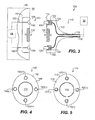
- Figure 3 illustrates a cross-sectional view of an embodiment of a magnetic connector according to certain teachings of the present disclosure.
- Figure 4 illustrates a front view of a receptacle of the magnetic connector of Figure 3 .
- Figure 5 illustrates a front view of a plug of the magnetic connector of Figure 3 .
- Figure 6 illustrates an ability of the disclosed magnetic connector to prevent possible damage.
- Figure 7 illustrates an alternative embodiment of the magnetic connector of Figure 3 .
- Figures 8A-8B illustrate a plug of another embodiment of a magnetic connector according to certain teachings of the present disclosure.
- Figures 9A-9B illustrate a receptacle for the plug of the disclosed magnetic connector of Figures 8A-8B .
- Figure 10 illustrates a perspective view of the plug and receptacle for the disclosed magnetic connector of Figures 8A-8B and 9A-9B .
- Figures 11A-11B illustrate an embodiment of a magnetic connector according to certain teachings of the present disclosure having a plurality of magnets and a back plate.
- Figures 12A-12B illustrate another embodiment of a magnetic connector according to certain teachings of the present disclosure having a plurality of magnets and a back plate.
- FIGS 13A-13B illustrate embodiments of magnetic connectors according to certain teachings of the present disclosure having electromagnets.
- Figure 14 illustrates an embodiment of a magnetic connector according to certain teachings of the present disclosure having an electromagnet and switch element.
- Figure 15 illustrates an embodiment of a magnetic connector according to certain teachings of the present disclosure having an electromagnet and a proximity sensor.
- Figure 16 illustrates an embodiment of a magnetic connector according to certain teachings of the present disclosure having an electromagnet and fault detector.
- Figure 17 illustrates an embodiment of a magnetic connector according to certain teachings of the present disclosure having two electromagnets and fault detector.
- Figure 18 illustrates an embodiment of a magnetic connector according to certain teachings of the present disclosure having an electromagnet and control circuitry.
- the magnetic connector 100 includes a first connector or plug 110 and a second connector or receptacle 150.
- the plug 110 is connectable to a first device or electrical relation 50, while the receptacle 150 is connectable to a second device 60.
- the first device 50 is a transformer
- the second device 60 is an electronic device, such as a laptop computer, having a housing 62 and internal electronics 64. Therefore, in one embodiment, the magnetic connector 100 can be part of a power adapter for connecting the laptop computer 60 to a conventional AC power supply (not shown) with the transformer 50.
- the magnetic connector 100 is preferably rated for 6A at 24V, and the plug 110 and receptacle 150 can both be approximately 4-mm tall and 6-mm wide.
- the plug 110 includes a plug body 112 having a face 118 and connected to a cable 114.
- the body 112 is composed of a conventional non-conductive material.
- the body 112 houses internal wires 116 of the cable 114, which connects to the first device 50.
- a plurality of first electrical contacts 120 and a first magnetic element 130 are positioned on the plug body 112.
- the first electrical contacts 120 are preferably plated and spring loaded pins to maintain contact with the corresponding contacts on the receptacle 150.
- the pins 120 are held in housings 124 and are connected to the wires 116 of the cable 114.
- Springs 122 bias the pins 120 so that they extend from the face 118 of the plug body 112.
- the first magnetic element 130 is embedded in the face 118 of the plug body 112.
- the receptacle 150 has a body 152 connected to the housing 62 of the second device 60.
- the body 152 has a face 158, a plurality of second electrical contacts 160, and a second magnetic element 140.
- the second electrical contacts 160 are plates embedded in the face 158 of the body 152 and electrically connected to the internal electronics 64 by wires 162 or the like.
- the second magnetic element 170 is embedded in the face 118 of the body 152.
- the face 118 of the plug 110 is positioned against the face 158 of the receptacle 150.
- the pins 120 on the plug 110 engage the plates 160 on the receptacle 150.
- the wires 116 connected to the first device 50 are electrically connected to the wires 162 connecting to the internal electronics 64 of the second device 60.
- electrical connection between pointed pins 120 and substantially flat plates 160 is preferred for a number of reasons, such as issues related to Hertzian stresses around a contact point and issues related to contact asperities or aspots.
- both magnetic elements 130 and 170 are magnets, either permanent or electromagnetic, arranged to attract magnetically to one another.
- either magnetic element 130 or 170 is a magnet, either permanent or electromagnetic, while the other complementary element is a ferromagnetic material.
- the permanent magnet used for the magnetic elements is preferably a permanent rare earth magnet because rare earth magnets have a high flux density compared to their size.
- the magnetic attraction or force of the plug 110 coupled to the receptacle 150 can be configured for a particular implementation as desired.
- the magnetic field produced by the magnetic attraction between the elements 130 and 170 is small enough not to interfere with the supply of power through the electrical contacts 120 and 160.
- the receptacle 150 may be positioned on the housing 150 at a location away from various components.
- the receptacle 150 may be positioned away from disk drives, USB ports, internal busses, etc. of a laptop computer.
- the elements 130 and 170 may be shielded from various components of the electronic device, or a flux bar may be used to direct any magnetic flux of the elements 130 and 170 away from various components.
- the receptacle 150 has four electrical plates 160 positioned around the centrally located magnetic element 170.
- the body 152 of the receptacle is oval or oblong and has two axes of symmetry.
- two of the electrical plates 160(+) may be positive contacts, and two of the plates 120(-) may be negative contacts.
- Various arrangements are possible and would be within the abilities on one skilled in the art.
- the plug 110 is made to correspond with the arrangement of the receptacle 150 in Figure 4 . Therefore, the body 112 of the plug 110 is also oval, and the plug has four pins 120 positioned around the magnetic element 130, which is centrally located on the plug 110.
- the plug 110 connected to an AC to DC transformer two of the electrical contacts 120(+) are positive contacts, and two of the contacts 120(-) are negative contacts.
- the arrangement of the pins 120 and plates 160 is symmetrical along the axes of symmetry defined by the oval or oblong shape of the bodies 112 and 152.
- the plug 110 and receptacle 150 can be coupled in only two ways, and proper alignment of positive pins 120(+) with positive plates 160(+) and of negative pins 120(-) with negative plates 160(-) will be ensured.
- the plug 110 and receptacle 150 are shown having one magnetic element 130 and 170 each, it will be appreciated that each can include one or more magnetic elements.
- the plug 110 and receptacle 150 can each have one or more contacts, depending on the type of electrical connection to be made. For example, additional pins and contacts may be symmetrically arranged around the plug 110 and receptacle 150 for passing electrical signals between two devices, such as a laptop computer and power adapter.
- the magnetic connector 100 substantially avoids damage because male components are not required to have an interference fit with female components to maintain both electrical and mechanical connection. Instead, a user of the connector 100 needs only to position the faces 118 and 158 of the plug 110 and receptacle 150 against or away from one another when making or releasing the electrical and magnetic connection therebetween. Being biased towards plates 160, the pins 120 can avoid damage while still maintaining contact with the plates 160.
- the magnetic connector 100 can substantially avoid damage by allowing the plug 110 and receptacle 150 to break free of one another when inadvertently pulled away from each other by a non-axial force. Although shown slightly recessed in the device 60, the face 158 of the receptacle 150 can also be flush with the housing or can protrude therefrom. However, the recess is used to prevent stray magnetic fields from interfering with other devices.
- FIG. 7 another embodiment of a magnetic connector 200 according to certain teachings of the present disclosure is illustrated.
- This embodiment is substantially similar to the embodiment of Figures 3 through 5 so that like reference numbers indicate similar components.
- the receptacle 250 in this embodiment is not housed in a device (not shown) to which it is connected as with previous embodiments. Rather, the receptacle 250 resembles the plug 110 in that it has a body 252 that connects to the device with a cable 254.
- the bodies 112 and 252 of the plug 110 and receptacle 150 are substantially round.
- the plug 110 and receptacle 150 have complementary guides 119 and 159 that allow for only one way of coupling them together. Although the guides 119 and 159 are shown on the faces 118 and 158 of the plug 110 and receptacle 150, it will be appreciated by one skilled in the art that a number of guides and techniques can be used to ensure proper alignment.
- FIG. 8A-8B and 9A-9B another embodiment of a magnetic connector according to certain teachings of the present disclosure is illustrated.
- a first connector or plug 310 of the magnetic connector is shown in a partial side cross-section and in a front view of Figures 8A-8B .
- a second connector or receptacle 350 of the magnetic connector is shown in a partial side cross-section and in a front view of Figures 9A-9B .
- Both the plug 310 and receptacle 350 can be at least partially composed of transparent, non-conductive material and can include internal lights, such as LEDs, to illuminate them.
- the plug 310 includes a body 312, a plurality of pins 320, and a first magnetic element 330, and a shell 340.
- the body 312 is made of any suitable non-conductive material and has an oblong shape with two axes of symmetry A 1 and A 2 .
- the body 312 houses internal wires 316 of a cable 314, which connect the pins 320 to a first device (not shown), such as a transformer, for example.
- the pins 320 are biased by springs, and the pins 320 extend from a face 318, which is slightly recessed in the plug body 312.
- the first magnetic element 330 is positioned on the end of the plug body 312. As best shown in Figure 8B , the first magnetic element 330 surrounds the recessed face 318 of the body 318.
- the centrally located pin 320 can be designated for signals used by the electronic device to determine the type of transformer or other device attached by the plug 310.
- the two outer located pins 320 can be designated for the positive DC power, and the outer shell 340 is designated for the return path of DC power. In this way, any orientation of the plug 310 will ensure proper connection of positive pins 320(+) and signal pin 320(S) of the plug 310 with corresponding contacts of the receptacle (350; Figs. 9A-9B ).
- Using the outer shell 340 for the return path is preferred because the plug 310 can have a smaller profile.
- the return path can be provided by additional pins (not shown) on the plug 310 and receptacle 350.
- additional pins (not shown) for the additional return path could be provided and symmetrically arranged on the plug 310 such that the pins would only align with corresponding contacts (not shown) of the receptacle 350 regardless of the orientation in which the plug 310 is coupled to the receptacle 350.
- the receptacle 350 has a body 352, a plurality of contacts 360, and a second magnetic element 370, and a shell 380.
- the body 352 has a casing 356 with legs 357 for mechanical connection to a printed circuit board of internal electronics of a second device (not shown), such as a laptop computer, for example.
- the casing 356 can be composed of a conductive or non-conductive material.
- the body 352 has an oblong shape with two axes of symmetry A 1 and A 2 and is made of any suitable non-conductive material.
- the body 352 also has snap connectors 359 for mechanical connection to a mounting base (not shown).
- the receptacle 350 has pins 364 for connecting the contacts 360 to internal electronics of the device.
- the body 352 has an end 354 intended to extend outside the device housing the receptacle 350. This end 354 may be illuminated by techniques known in the art.
- the contacts 360 are positioned in a face 358 of the body 352. In the present embodiment, the contacts 360 are substantially flat plates electrically connected to the pins 364 by wires 362.
- the second magnetic element 370 is positioned about the face 358, and the second magnetic element 370 is preferably recessed from the face 358. Preferably, the recess of the second magnetic element 370 is slight and is comparable to the recess of the face (318) of the plug (310) in Figure 8A .
- the plates 360 are arranged to correspond with the positive pins (320(+)) and signal pin (320(S)) of the plug (310) of Figures 8A-8B , as described previously.
- the face 318 of the plug 310 of Figure 8A is positioned against the face 358 of the receptacle 350 of Figure 9A .
- the pins 320 on the plug 310 engage the plates 360 on the receptacle 350.
- the first and second magnetic elements 330 and 370 magnetically couple together and hold the plug 310 to the receptacle 350.
- the magnetic elements 330 and 370 are both permanent magnets (preferably rare earth magnets) arranged to magnetically couple together.
- one of the magnetic elements 330 and 370 can be a permanent magnet (preferably a rare earth magnet) or an electromagnet while the other element is a ferromagnetic material.
- FIG. 10 additional details of the plug 310 and receptacle 350 for the disclosed magnetic connector of Figures 8A-8B and 9A-9B are illustrated in a perspective view. Portions of the plug 310 and receptacle 350 are not illustrated so that various details can be better shown.
- the shell 340 abuts the magnetic element 310, which can be a ferromagnetic material.
- the shell 340 has an extension 342 for connecting to the return path of the power supply from the adapter (not shown) to which the plug 310 is connected.
- Three connectors 322(+), 322(S), and 322(+) extend from the back end of the body 312 for connecting the pins (not shown) with the positive power and signal from adapter to which the plug 310 is connected.
- the shell 380 for the return path of the power is positioned within the casing 356, and the magnetic element 370, which can be a permanent magnet, is positioned within the shell 380.
- An opening 372 through the magnetic element 370 allows for passage of body material (not shown) and contacts (not shown), as disclosed previously.
- Tabs or holders 382 of the shell 380 contact and hold the magnetic element 370.
- a leg 384 of the shell 380 extends from the receptacle 350 as do legs 357 of the casing 356.
- the ferromagnetic material 330 of the plug 310 positions against the permanent magnet 370 and the inside of the casing 380 of the receptacle 350.
- the magnetic engagement between the ferromagnetic material 330 and the permanent magnet 370 holds the plug 310 to the receptacle.
- the physical engagement between the ferromagnetic material 330 and the casing 380 creates the return path for power from the receptacle's shell pin 384 to the plug's shell pin 342.
- FIGS. 11A-11B an embodiment of a magnetic connector 360 according to certain teachings of the present disclosure is illustrated.
- the connector 360 is compact and preferably has a low profile.
- a plug 370 of the connector 360 is shown in a front perspective.
- Figure 11B some of the internal components of plug 370 and a receptacle 390 are shown in a back perspective.
- the receptacle 390 is housed in an electronic device (not shown), and the plug 370 attaches to a cord or the like (not shown).
- the plug 370 has magnets 380, 382 positioned on both sides of a plurality of contacts 376, which are similar to other contacts disclosed herein.
- the central contact 376 is designated for a first path of electrical communication, and the two outer contacts 376 are designated for a second path of electrical communication.
- the contacts 376 are biased pins where the central pin 376 carries a signal path and the two side pins carry a positive current.
- the magnets 380, 382 are arranged with opposite polarities, as indicated by the direction of the arrows in Figure 11A .
- the magnets 380, 382 are also designated for a third path of electrical communication.
- the plug 370 also has a back plate 372 connected between the back ends of the magnets 380, 382.
- the back plate 372 is made of a ferromagnetic material, such as steel.
- the receptacle 390 has an attraction plate 392 also made of a ferromagnetic material, such as steel. When the attraction plate 392 of receptacle 390 is attracted to the magnets 380, 382, the magnetic field lines travel through the steel attraction plate 392 from one magnet to the other, completing the magnetic circuit and producing a strong attracting force.
- the attraction plate 392 of receptacle 390 defines an opening 394 for passage of the electrical contacts (not shown in Figure 11B ).
- the back plate 372 of the plug 370 defines openings 374 for passage of leads from the electrical contacts (not shown).
- the magnets 380, 382 can form a path of electrical communication between the receptacle 390 and the plug 370.
- the magnets 380 and 382 and the attraction plate 392 carry negative current.
- the attraction plate 392 of the receptacle 390 includes a connector 396 for connecting to an electrical lead or the like (not shown).
- the plates 372 and 392 must give up a certain amount of material to produce the openings 374 and 394.
- magnetic attractive force can be limited because the flux density can saturate the narrower portions of ferromagnetic material in both the attraction plate 392 and the back plate 374.
- magnetic strength is a function of magnet thickness to cross section ratio (with thickness being defined by the dimension along the direction of magnetization).
- FIG. 12A-12B another embodiment of a magnetic connector 360 according to certain teachings of the present disclosure is illustrated.
- the magnetic connector 360 in Figures 12A-12B is substantially similar to that disclosed above so those like numerals indicate similar components between the embodiments.
- the plug 370 houses four magnets 380, 381, 382, and 383.
- the magnets 380, 381, 382, and 383 are arranged with opposite polarities, as indicated by the arrows in Figure 12A .
- the four magnets 380, 381, 382, and 383 form four magnetic circuits for the travel of magnetic flux.
- the magnetic attraction or force coupling the plug 370 and the receptacle 390 can be configured as desired for a given implementation.
- a straight pullout force to uncouple the plug 370 from the receptacle 390 is preferably between 3-lbf and 7-lbf, It should be noted that pulling the plug 370 out sideways, up, or down can produce torque.
- the magnetic attraction produces less torque in the up direction but produces more torque in the other directions.
- Target torque values can be 0.5 kgf-cm for the up direction and 0.7 to 1.5 kgf-cm in the other directions.
- the asymmetrical torque values can be achieved by extending the upper magnets 380 and 382 upwards. In this way, the upper magnets 380 and 382 are stronger and provide more attraction upwards than the lower magnets 381 and 383. One resulting effect is that there can be more holding force and displacement of the application point of the force upward, subsequently leading to more torque. This also helps compensate for any downward torque that may be produced by a cable (not shown) coupled to the plug 370.
- the asymmetrical torque values can be achieved by changing the angle of the magnetic flux lines in the upper magnets 380 and 382.
- the separate, upper magnets 380 and 382 can have flux direction that point downward at an approximately 20-degree angle in comparison to the direction of coupling.
- the connector 400 includes a plug 410 and a receptacle 450.
- the plug 410 is not substantially different from that disclosed in the embodiment of Figure 8A-8B .
- the plug 410 has contacts 420 for conveying power from a transformer (not shown) and has a magnetic element 430, which can be a ferromagnetic material.
- the receptacle 450 has contacts 460 for conveying power to internal electronics 76 of the device 70, which is a laptop computer in the present embodiment.
- the receptacle 450 has an electromagnet formed by a metal core 470 wrapped by a wire coil 472.
- Using an electromagnet in the plug 410 or receptacle 450 can overcome some of the disadvantages of having a permanent magnet on either the plug 410 or receptacle 450.
- the electromagnet may reduce potential interference with internal components of the electronic device 70 or storage media.
- the coil 472 is connected to a power supply or battery 72 of the laptop 70, and an internal switch 74 among other electronics can be used to operate the electromagnet of the core 470 and coil 472.
- the internal switch 74 causes power from the battery 72 to energized the electromagnet of core 470 and coil 472. Consequently, the energized electromagnet produces a magnetic field that attracts the ferromagnetic material 430 of the plug 410 and that can hold the plug 410 to the receptacle 450.
- the battery 72 can be an independent battery of the device or can be the same battery used to power the internal electronics 76 of the device 70. In either case, operation of the internal switch 74 and other electronics for connecting the battery 72 to the electromagnetic is preferably controlled to conserve power consumption of the battery 72.
- the connector 500 includes a plug 510 and a receptacle 550.
- the receptacle 550 is not substantially different from that disclosed in the embodiment of Figure 9A-9B .
- the receptacle 550 has contacts 560 for conveying power and signals to internal electronics 76 of the device 70.
- the receptacle 550 also has a magnetic element 570, which can be a ferromagnetic material.
- the plug 510 has contacts 520 for conveying power and signals from a power supply, such as power adapter 80, via wires 522 of a cable 86.
- the plug 510 has an electromagnet formed by a metal core 530 wrapped by a wire coil 532.
- the coil 532 is connected to a power supply by wires 534.
- the coil 532 can draw power output from the transformer 82 of the adapter 80, form a conventional power supply to which the outlet plug 88 connects, or from a battery 84 housed internally in the adapter 80.
- Use of the battery 84 can overcome the need for a user to first connect the adapter 80 to the power supply before the electromagnet in the plug 510 is operated and can magnetically connect to the receptacle 550.
- the drawn power energizes the electromagnet of core 530 and coil 532 to produce a magnetic attraction to the ferromagnetic material 570 that can hold the plug 510 to the receptacle 550.
- the connector 600 has a plug 602 having contacts 604 and an electromagnet 606.
- the connector 600 also has a receptacle 620 positioned on a portable computer or electronic device 630.
- the receptacle 620 has an attraction plate or magnet 622 and contacts 624.
- the contacts 624 act as paths for electrical communication so that they are electrically coupled to internal electronics 632 of electronic device 630.
- the attraction plate or magnet 622 acts as a path of electrical communication so that it is also electrically coupled to the internal electronics 632.
- various components such as leads, contacts, and coils, are not shown for simplicity.
- the electromagnet 606 is in the plug 602; however, it can be positioned in the receptacle 620.
- the electromagnet 606 derives its power from circuitry 612 of the power adapter 608 so the electromagnet 606 does not drain a battery (not shown) of the electronic device 630.
- the plug 602 includes a switch element 610 interrupting the electrical connection between the electromagnet 606 and the circuitry 612 of the adapter 608.
- the switch element 610 includes a mechanical switch that a user presses to turn the electromagnet 602 on and off. Any mechanical switch, such as a conventional micro-switch, for controlling the power load of the electromagnet 602 is suitable for the connector 600. In general, the switch element 610 allows the electromagnet 606 to run directly from power of the adapter 608.
- the switch element 610 includes a touch sensor that energizes (e.g ., turns on) the electromagnet 606 when a user touches the sensor 610 by picking up the plug 602.
- Touch sensors are known in the art.
- the touch sensor 610 can include logic circuitry and contacts (not shown) and can use principals of capacitance of the human body for operation.
- the electromagnet 606 can remain energized for a time interval to allow the user to couple the plug 602 to the receptacle 620 and to turn on the electronic device 630.
- the contacts 604 and 624 that form a signal path between the adapter 608 and the device 630, and a signal along the signal path can be used to keep the touch sensor 610 activated and the electromagnet 606 energized.
- the touch sensor 610 can turn off the electromagnet 606 when touched to allow the user to disconnect the plug 602.
- the touch sensor 610 can reduce the energization of the electromagnet 606 to enable easy removal by the user but to keep a small remaining attraction.
- the device 630 may no longer send a signal along the signal path of the contacts 604 and 624 or may send a quit signal to the touch sensor 610 to stop energization of the electromagnet 606. Then, the de-energized electromagnet 606 can allow the plug 602 to be released from the electronic device 630.
- the switch element 610 includes a motion sensor, which detects when the plug 602 is moved.
- the motion sensor 610 can maintain the electromagnet 606 energized for a time interval to allow the user to couple the plug 602 with the receptacle 620 and to turn on the electronic device 630.
- the signal path formed by contacts 604 and 624 can allow a signal to control the circuitry of the motions sensor 610 to maintain it activated while coupled to the device 630.
- the motion sensor 610 can automatically shut off the electromagnet 606 so as to release the plug 602 from the device 630 if a sudden movement occurs (e.g., the device 630 is dropped or pulled away with the plug 602 connected).
- FIG. 15 an embodiment of a magnetic connector 600 according to certain teachings of the present disclosure is illustrated having an electromagnet 606 and a proximity sensor 640.
- Reference numerals in Figure 15 that are the same as those in other Figures represent like components between embodiments.
- the proximity sensor 640 is positioned in the plug 602 and is coupled to a switch element 642.
- the electromagnet 606 is also coupled to the switch element 642, which in turn is coupled to circuitry 644 for providing power located in the adapter 608.
- the proximity sensor 640 and switch element 642 turn on the electromagnet 606 when the sensor 640 is positioned near plate 622 of the receptacle 620.
- the proximity sensor 640 includes a Hall Effect sensor, which detects magnetic field levels.
- the electromagnet 606 is initially energized before being coupled to the receptacle 620.
- the initial energization can be achieved, for example, when the adapter 608 is coupled to a power source (not shown) or when a touch sensor (not shown) or the like is activated by the user.
- the initial energization can be less than that necessary to magnetically couple the electromagnet 606 to the plate 622.
- the magnetic field associated with the initial energization of the electromagnet 606 is changed, which is subsequently detected by the Hall Effect sensor 640.
- the sensor 640 causes the energization of the electromagnet 606 to be increased to allow it to magnetically couple to the attraction plate 622.
- FIG. 16 an embodiment of a magnetic connector 600 according to certain teachings of the present disclosure is illustrated having an electromagnet 606 and fault detection circuitry 650.
- Reference numerals in Figure 16 that are the same as those in other Figures represent like components between embodiments.
- the electromagnet 606 is energized to magnetically couple with the attraction plate 626 of receptacle 620, which can be ferromagnetic material or a permanent magnet.
- the fault detection circuitry 650 detects a fault event caused, for example, by a surge or spike in the power supply.
- the fault detection circuitry 650 can be similar to that commonly used in the art for power adapters. In one embodiment, for example, the fault detection circuitry 650 can include circuitry for detecting an over-current. In another embodiment, for example, the fault detection circuitry 650 can include circuitry for detecting an over-temperature.
- the circuitry 650 can stop energizing the electromagnet 606 and allow the plug 602 to be released from the embodiment of the receptacle 620 having a ferromagnetic attraction plate 626.
- the circuitry 650 can reverse the direction of current supplied through the electromagnet 606 so the electromagnet 606 is repelled by the polarity of the embodiment of the receptacle 620 having a permanent magnet on the attraction plate 626. It will be appreciated that the electromagnet 606 and fault circuitry 650 can be positioned on the device 630 while the attraction plate can be positioned on the plug 602 of the connector 600 to achieve the same protection.
- FIG. 17 an embodiment of a magnetic connector 600 according to certain teachings of the present disclosure is illustrated having two electromagnets 606 and 660.
- the plug 602 has the first electromagnet 606, which is energized by the power adapter 608.
- the receptacle 620 positioned in the device 630 has the second electromagnet 660, which is power by an internal power supply 662, such as a battery.
- the two electromagnets 606 and 660 have opposite polarities allowing them to be magnetically coupled.
- the adapter 608 includes fault detection circuitry 650.
- fault detection circuitry 662 When a fault is detected by fault detection circuitry 662, the polarity of the first electromagnet 606 can be reversed by the circuitry 650 so that the first and second electromagnets 606 and 660 repel one another and actively prevent connection.
- the adapter 608 includes circuitry 650 for identifying the adapter 608.
- the identification circuitry 650 can identify a type of electronic device to which it is intended to be connected or can even identify a specific device to which is can only be used.
- the first electromagnet 606 can be energized according to the techniques disclosed herein.
- the second electromagnet 660 can remain de-energized.
- the signal path formed by contacts 604 and 624 allow the identification circuitry 650 to send a signal to the internal electronics 632 of the device, which can identify the adapter 608 being connected to the device 630.
- the second electromagnet 660 can be energized with opposite polarity to couple with the first electromagnet 606, or the second electromagnet 660 can remain de-energized while the first electromagnet 606 is simply allowed to magnetically couple with the ferromagnetic components of the de-energized electromagnet 660. If, on the other hand, the adapter 608 is not intended for the device 630, then the second electromagnet 660 can be energized with the same polarity to repel the first electromagnet 606 and actively prevent connection.
- the control circuitry 670 includes a switch element, which receives a control signal from the internal electronics 632 of the device 630.
- the internal electronics 632 sends a control signal to the control circuitry 670 via the signal path formed by contacts 604 and 624.
- the internal electronics 632 detects a fault, it can send a control signal to the control circuitry 670.
- one of the contacts 604 on the plug 602 and one of the contracts 624 on the receptacle 620 can form a signal path between the device 630 and the adapter 608. It is along such a signal path that the control signal indicating the fully charged battery is sent.
- the control circuitry 670 causes its internal switch element to stop energization of the electromagnet 606, and the plug 602 becomes decoupled from the receptacle 626.
- the plate 627 on the receptacle 620 can include a magnet (not shown) for maintaining at least some magnetic coupling with ferromagnetic material of the electromagnet 606.
- control circuitry 670 receives a control signal, which governs whether the adapter 608 associated with the control circuitry 670 can operate with the electronic device 630.
- the internal electronics 632 on the device 630 produces a control signal that identifies the device 630, such as by its make or model.
- the control signal can be a digital signal, for example, identifying the device 630.
- the control circuitry 670 in the adapter 608 is pre-configured to energize the electromagnet 606 only when the identifying control signal is received.
- the control circuitry includes a switch element for controlling the electrical connection of the electromagnet 606 with its energizing source, and the circuitry includes a logic element for interpreting the control signal and activating the switch element.
- the signal contacts 604 and 624 on the plug and receptacle 602 and 620 will make contact, allowing the internal electronics 632 of the device 630 to communicate its identifying control signal to the control circuitry 670 of the adapter 608. If the circuitry 670 receives the correct signal, an internal switch within the circuitry causes the electromagnet 606 to be energized for coupling with the receptacle. Otherwise, the electromagnet will not be energized, and the plug 602 will not stay coupled to the receptacle 620.
- the electromagnet 606 on the adapter 608 will only be energized for a particular model or type of device, which may prevent the possibility of a user inadvertently coupling an adapter with a specific power rating to a device requiring a different power rating.
- harm to a computer can be prevented because the computer will not allowing itself to be connected to the wrong type of power adapter (e.g ., one that supplies a higher voltage than the computer's specification).
- the control circuitry 670 and identification of the device 630 can be configured so that the device 630 will only draw power only from a particular power adapter or a group of power adapters. Such a configuration can be useful in various settings, such as a school or other public organization, to discourage theft.
- control circuitry 670 includes a security system, which requires the user to enter a particular code or other identification. Without the entered code, the control circuitry 670 will not energize the electromagnet, and the plug 602 will not engage with the receptacle 620.
- embodiments of magnetic connectors have been disclosed in the context of providing power from a transformer to a laptop computer.
- the subject matter of the present disclosure is applicable to various types of connectors, which provide electrical connection in the form of power and/or signals between an electronic device and any of a number of electronic devices or electrical relations.
- other applicable electronic devices or electrical relations include portable DVD players, CD players, radios, printers, portable memory devices, portable disk drives, input/output devices, power sources, batteries, etc.
- Other applicable types of electrical connections that can be provided by the connectors of the present disclosure include Universal Serial Bus, D-subminiature, FireWire, network connectors, docking connectors, etc.
Landscapes
- Details Of Connecting Devices For Male And Female Coupling (AREA)
- Charge And Discharge Circuits For Batteries Or The Like (AREA)
Priority Applications (1)
| Application Number | Priority Date | Filing Date | Title |
|---|---|---|---|
| PL09159211T PL2096720T3 (pl) | 2005-09-26 | 2006-08-11 | Złącze elektromagnetyczne dla urządzenia elektronicznego |
Applications Claiming Priority (2)
| Application Number | Priority Date | Filing Date | Title |
|---|---|---|---|
| US11/235,873 US7351066B2 (en) | 2005-09-26 | 2005-09-26 | Electromagnetic connector for electronic device |
| EP06789733.0A EP1941587B1 (de) | 2005-09-26 | 2006-08-11 | Elektromagnetischer verbinder für ein elektronisches gerät |
Related Parent Applications (3)
| Application Number | Title | Priority Date | Filing Date |
|---|---|---|---|
| EP06789733.0 Division | 2006-08-11 | ||
| EP06789733.0A Division-Into EP1941587B1 (de) | 2005-09-26 | 2006-08-11 | Elektromagnetischer verbinder für ein elektronisches gerät |
| EP06789733.0A Division EP1941587B1 (de) | 2005-09-26 | 2006-08-11 | Elektromagnetischer verbinder für ein elektronisches gerät |
Publications (2)
| Publication Number | Publication Date |
|---|---|
| EP2096720A1 true EP2096720A1 (de) | 2009-09-02 |
| EP2096720B1 EP2096720B1 (de) | 2011-11-23 |
Family
ID=37450880
Family Applications (9)
| Application Number | Title | Priority Date | Filing Date |
|---|---|---|---|
| EP10011084.0A Active EP2290756B1 (de) | 2005-09-26 | 2006-08-11 | Elektromagnetischer Verbinder für einen elektronischen Gegenstand |
| EP16189686.5A Active EP3136518B1 (de) | 2005-09-26 | 2006-08-11 | Elektromagnetischer verbinder für elektronische vorrichtungen |
| EP13177584.3A Active EP2665139B1 (de) | 2005-09-26 | 2006-08-11 | Elektromagnetischer Verbinder für elektronische Vorrichtungen |
| EP10011081A Active EP2287972B1 (de) | 2005-09-26 | 2006-08-11 | Elektromagnetischer Verbinder für einen elektronischen Gegenstand |
| EP06789733.0A Active EP1941587B1 (de) | 2005-09-26 | 2006-08-11 | Elektromagnetischer verbinder für ein elektronisches gerät |
| EP11176682.0A Active EP2387114B1 (de) | 2005-09-26 | 2006-08-11 | Elektromagnetischer Verbinder für elektronische Vorrichtungen |
| EP10011083.2A Active EP2290755B1 (de) | 2005-09-26 | 2006-08-11 | Elektromagnetischer Verbinder für einen elektronischen Gegenstand |
| EP10011082.4A Revoked EP2290754B1 (de) | 2005-09-26 | 2006-08-11 | Elektromagnetischer Verbinder für einen elektronischen Gegenstand |
| EP09159211A Revoked EP2096720B1 (de) | 2005-09-26 | 2006-08-11 | Elektromagnetischer Verbinder für elektronische Vorrichtungen |
Family Applications Before (8)
| Application Number | Title | Priority Date | Filing Date |
|---|---|---|---|
| EP10011084.0A Active EP2290756B1 (de) | 2005-09-26 | 2006-08-11 | Elektromagnetischer Verbinder für einen elektronischen Gegenstand |
| EP16189686.5A Active EP3136518B1 (de) | 2005-09-26 | 2006-08-11 | Elektromagnetischer verbinder für elektronische vorrichtungen |
| EP13177584.3A Active EP2665139B1 (de) | 2005-09-26 | 2006-08-11 | Elektromagnetischer Verbinder für elektronische Vorrichtungen |
| EP10011081A Active EP2287972B1 (de) | 2005-09-26 | 2006-08-11 | Elektromagnetischer Verbinder für einen elektronischen Gegenstand |
| EP06789733.0A Active EP1941587B1 (de) | 2005-09-26 | 2006-08-11 | Elektromagnetischer verbinder für ein elektronisches gerät |
| EP11176682.0A Active EP2387114B1 (de) | 2005-09-26 | 2006-08-11 | Elektromagnetischer Verbinder für elektronische Vorrichtungen |
| EP10011083.2A Active EP2290755B1 (de) | 2005-09-26 | 2006-08-11 | Elektromagnetischer Verbinder für einen elektronischen Gegenstand |
| EP10011082.4A Revoked EP2290754B1 (de) | 2005-09-26 | 2006-08-11 | Elektromagnetischer Verbinder für einen elektronischen Gegenstand |
Country Status (14)
| Country | Link |
|---|---|
| US (5) | US7351066B2 (de) |
| EP (9) | EP2290756B1 (de) |
| JP (1) | JP4774439B2 (de) |
| KR (1) | KR101013036B1 (de) |
| CN (3) | CN102664331B (de) |
| AT (1) | ATE535041T1 (de) |
| AU (2) | AU2006295352A1 (de) |
| CA (3) | CA2700652C (de) |
| DK (1) | DK2096720T3 (de) |
| ES (3) | ES2431821T3 (de) |
| GB (2) | GB2444689B (de) |
| HK (6) | HK1153855A1 (de) |
| PL (1) | PL2096720T3 (de) |
| WO (1) | WO2007037807A1 (de) |
Cited By (2)
| Publication number | Priority date | Publication date | Assignee | Title |
|---|---|---|---|---|
| TWI425720B (zh) * | 2011-08-01 | 2014-02-01 | Simula Technoligy Inc | Magnetic connector structure |
| CN104682092B (zh) * | 2013-12-03 | 2017-05-10 | 河北建筑工程学院 | 一种弱磁力定位接插件 |
Families Citing this family (388)
| Publication number | Priority date | Publication date | Assignee | Title |
|---|---|---|---|---|
| US7114990B2 (en) | 2005-01-25 | 2006-10-03 | Corning Gilbert Incorporated | Coaxial cable connector with grounding member |
| US20070028780A1 (en) * | 2005-08-08 | 2007-02-08 | Popeil Ronald M | Cooking device to deep fat fry foods |
| US20110203570A1 (en) * | 2005-08-08 | 2011-08-25 | Popeil Ronald M | Device to efficiently cook foods using liquids and hot vapors |
| US8707857B2 (en) * | 2005-08-08 | 2014-04-29 | Ronald M. Popeil | Cooking device to deep fat fry foods |
| US20070055396A1 (en) * | 2005-09-02 | 2007-03-08 | Hedges Christopher A | Portable media player |
| US7311526B2 (en) | 2005-09-26 | 2007-12-25 | Apple Inc. | Magnetic connector for electronic device |
| US7351066B2 (en) | 2005-09-26 | 2008-04-01 | Apple Computer, Inc. | Electromagnetic connector for electronic device |
| US8401219B2 (en) | 2007-01-05 | 2013-03-19 | Apple Inc. | Headset connector |
| US7607243B2 (en) | 2006-05-03 | 2009-10-27 | Nike, Inc. | Athletic or other performance sensing systems |
| JP5176955B2 (ja) * | 2006-06-02 | 2013-04-03 | 日本電気株式会社 | 電子機器及びコネクタの嵌合方法 |
| US7467948B2 (en) * | 2006-06-08 | 2008-12-23 | Nokia Corporation | Magnetic connector for mobile electronic devices |
| US7741806B2 (en) * | 2006-08-25 | 2010-06-22 | Meridian Design, Inc. | Magnetically attachable battery recharging |
| US20080103021A1 (en) * | 2006-10-30 | 2008-05-01 | Forhouse Corporation | Guiding structure of a treadmill for guiding electrostatic charges of a human body |
| US8180093B2 (en) * | 2007-01-05 | 2012-05-15 | Apple Inc. | Assembly for coupling the housings of an electronic device |
| US9118990B2 (en) | 2007-01-06 | 2015-08-25 | Apple Inc. | Connectors designed for ease of use |
| EP2421101B1 (de) | 2007-01-06 | 2013-09-11 | Apple Inc. | Headsetanschluss zur selektiven Weiterleitung von Signalen in Abhängigkeit der bestimmten Ausrichtung des angeschlossenen Steckverbinders |
| CN104202689B (zh) | 2007-01-06 | 2018-07-20 | 苹果公司 | 依照确定的啮合连接器的方向选择性路由信号的耳机连接器 |
| US7798831B2 (en) | 2007-01-06 | 2010-09-21 | Apple Inc. | Connector assemblies |
| US7658613B1 (en) * | 2007-01-16 | 2010-02-09 | Griffin Technology Inc | Magnetic connector |
| US7859219B2 (en) * | 2007-02-07 | 2010-12-28 | David M Harris | Disconnect for a charging unit for an electric vehicle |
| US20080230623A1 (en) * | 2007-03-22 | 2008-09-25 | Macnow Donald H | Portable remote control valve actuator apparatus |
| RU2474386C2 (ru) * | 2007-06-01 | 2013-02-10 | Конинклейке Филипс Электроникс, Н.В. | Кабель беспроводного ультразвукового зонда |
| RU2502470C2 (ru) * | 2007-06-01 | 2013-12-27 | Конинклейке Филипс Электроникс, Н.В. | Облегченный беспроводной ультразвуковой датчик |
| US7722358B2 (en) * | 2007-06-15 | 2010-05-25 | Microsoft Corporation | Electrical connection between devices |
| US7671559B2 (en) * | 2007-07-31 | 2010-03-02 | Apple Inc. | Battery charging system and mobile and accessory devices |
| US20090054208A1 (en) * | 2007-08-20 | 2009-02-26 | Shen Yi Wu | Safety device for motorized fitness equipment |
| WO2009033034A1 (en) | 2007-09-07 | 2009-03-12 | Nike, Inc. | Wearable device assembly having athletic functionality |
| US9407034B2 (en) * | 2007-09-14 | 2016-08-02 | Panasonic Avionics Corporation | Communication connector system and method |
| US7963773B2 (en) * | 2007-12-24 | 2011-06-21 | Craig Palli | Magnetic and locking cable connectors |
| US7762817B2 (en) * | 2008-01-04 | 2010-07-27 | Apple Inc. | System for coupling interfacing parts |
| US7771202B2 (en) | 2008-01-07 | 2010-08-10 | Einam Yitzhak Amotz | Apparatus for transferring alternating current electrical power |
| US7931472B2 (en) * | 2008-01-07 | 2011-04-26 | Arnon Haim David | Apparatus for transferring electric power from a mobile unit placed in various orientation on a stationary unit |
| WO2009086937A1 (de) * | 2008-01-11 | 2009-07-16 | Osram Gesellschaft mit beschränkter Haftung | Schaltungsanordnung zur authentifizierung von ernergieströmen |
| DE102008015388A1 (de) * | 2008-03-20 | 2009-06-04 | Otto Bock Healthcare Products Gmbh | System mit einer orthopädischen Einrichtung |
| EP2265341A1 (de) | 2008-04-02 | 2010-12-29 | Nike International Ltd. | Tragbare vorrichtungsanordnung für sportzwecke |
| US8174347B2 (en) | 2010-07-12 | 2012-05-08 | Correlated Magnetics Research, Llc | Multilevel correlated magnetic system and method for using the same |
| US8576036B2 (en) | 2010-12-10 | 2013-11-05 | Correlated Magnetics Research, Llc | System and method for affecting flux of multi-pole magnetic structures |
| US8816805B2 (en) | 2008-04-04 | 2014-08-26 | Correlated Magnetics Research, Llc. | Magnetic structure production |
| US9105380B2 (en) | 2008-04-04 | 2015-08-11 | Correlated Magnetics Research, Llc. | Magnetic attachment system |
| US9202616B2 (en) | 2009-06-02 | 2015-12-01 | Correlated Magnetics Research, Llc | Intelligent magnetic system |
| US8760250B2 (en) | 2009-06-02 | 2014-06-24 | Correlated Magnetics Rsearch, LLC. | System and method for energy generation |
| US7800471B2 (en) | 2008-04-04 | 2010-09-21 | Cedar Ridge Research, Llc | Field emission system and method |
| US8179219B2 (en) | 2008-04-04 | 2012-05-15 | Correlated Magnetics Research, Llc | Field emission system and method |
| US9371923B2 (en) | 2008-04-04 | 2016-06-21 | Correlated Magnetics Research, Llc | Magnetic valve assembly |
| US7893845B2 (en) * | 2008-04-25 | 2011-02-22 | Sony Ericsson Mobile Communications Ab | Socket and plug connector for electronic device |
| WO2009158413A2 (en) * | 2008-06-25 | 2009-12-30 | Launchpoint Technologies Inc. | High retention magnetic coupling device for conduit attachment |
| TWI454967B (zh) * | 2008-07-16 | 2014-10-01 | Htc Corp | 電子裝置及其鍵盤模組 |
| US9639187B2 (en) * | 2008-09-22 | 2017-05-02 | Apple Inc. | Using vibration to determine the motion of an input device |
| US9791634B2 (en) | 2008-09-30 | 2017-10-17 | Apple Inc. | Magnetic connector with optical signal path |
| US7841776B2 (en) * | 2008-09-30 | 2010-11-30 | Apple Inc. | Magnetic connector with optical signal path |
| CN101740945A (zh) * | 2008-11-26 | 2010-06-16 | 黄金富 | 采用磁力保持接合的易脱式安全连接器系统和相应方法 |
| EP2207241A3 (de) * | 2008-12-23 | 2013-04-03 | Einam Yizhak Amotz | Vorrichtung und Verfahren zum Übertragen von Energie von einer feststehenden Einheit zu einer tragbaren Einheit |
| JP5108747B2 (ja) | 2008-12-26 | 2012-12-26 | 富士フイルム株式会社 | 情報表示装置、方法およびプログラム |
| CN104115335A (zh) * | 2009-02-02 | 2014-10-22 | 艾派克斯技术股份有限公司 | 挠性磁性互连 |
| WO2010094060A1 (en) * | 2009-02-17 | 2010-08-26 | Imdex Technology Australia Pty Ltd | Modular core orientation system |
| US7873772B2 (en) * | 2009-02-17 | 2011-01-18 | Tyco Healthcare Group Lp | Portable and programmable medical device |
| US8388353B2 (en) | 2009-03-11 | 2013-03-05 | Cercacor Laboratories, Inc. | Magnetic connector |
| TW201037913A (en) * | 2009-04-03 | 2010-10-16 | Compal Electronics Inc | Electronic apparatus and connector thereof |
| CN101860047B (zh) * | 2009-04-11 | 2014-07-23 | 鸿富锦精密工业(深圳)有限公司 | 充电系统及对应的电子设备和充电装置以及自动断电方法 |
| ITFI20090085A1 (it) * | 2009-04-24 | 2010-10-25 | Marco Ariani | Sistema di illuminazione a led con fonti luminose posizionabili a piacere all'interno di un supporto metallico. |
| GB0907282D0 (en) * | 2009-04-28 | 2009-06-10 | Illinois Tool Works | Electrical connector |
| TWI487240B (zh) * | 2009-05-08 | 2015-06-01 | Hon Hai Prec Ind Co Ltd | 充電系統及對應的電子設備和充電裝置以及自動斷電方法 |
| US9257219B2 (en) | 2012-08-06 | 2016-02-09 | Correlated Magnetics Research, Llc. | System and method for magnetization |
| US9404776B2 (en) | 2009-06-02 | 2016-08-02 | Correlated Magnetics Research, Llc. | System and method for tailoring polarity transitions of magnetic structures |
| US9275783B2 (en) | 2012-10-15 | 2016-03-01 | Correlated Magnetics Research, Llc. | System and method for demagnetization of a magnetic structure region |
| US8704626B2 (en) | 2010-05-10 | 2014-04-22 | Correlated Magnetics Research, Llc | System and method for moving an object |
| US8427296B2 (en) * | 2009-07-14 | 2013-04-23 | Apple Inc. | Method and apparatus for determining the relative positions of connectors |
| US8742814B2 (en) | 2009-07-15 | 2014-06-03 | Yehuda Binder | Sequentially operated modules |
| US8602833B2 (en) | 2009-08-06 | 2013-12-10 | May Patents Ltd. | Puzzle with conductive path |
| EP2317330B1 (de) * | 2009-09-11 | 2013-12-11 | Giga-Byte Technology Co., Ltd. | Stabstecker und Chiptestbefestigung damit |
| US9711268B2 (en) | 2009-09-22 | 2017-07-18 | Correlated Magnetics Research, Llc | System and method for tailoring magnetic forces |
| WO2011037889A1 (en) * | 2009-09-22 | 2011-03-31 | Med-El Elektromedizinische Geraete Gmbh | Communications/audio interface with self-orienting magnet attachment system |
| US8807022B2 (en) * | 2009-10-12 | 2014-08-19 | Alan Backus | Devices and methods to disintegrate foods |
| US8535088B2 (en) | 2009-10-20 | 2013-09-17 | Apple Inc. | Magnetic connector having a unitary housing |
| KR101646520B1 (ko) * | 2009-11-03 | 2016-08-08 | 삼성전자주식회사 | 기기 간의 전기적 연결 구조 |
| TW201123642A (en) * | 2009-12-25 | 2011-07-01 | Hon Hai Prec Ind Co Ltd | Connector |
| US8348678B2 (en) * | 2010-01-11 | 2013-01-08 | Automotive Industrial Marketing Corp. | Magnetic cable connector systems |
| US9300081B2 (en) | 2010-02-02 | 2016-03-29 | Charles Albert Rudisill | Interposer connectors with magnetic components |
| US7874844B1 (en) | 2010-02-02 | 2011-01-25 | Fitts Jr Darrell Lynn | Universal magnetic power supply adaptor |
| CN102148432B (zh) * | 2010-02-08 | 2014-07-30 | 富士康(昆山)电脑接插件有限公司 | 线缆连接器组件 |
| CN101728703A (zh) * | 2010-03-02 | 2010-06-09 | 成都市华为赛门铁克科技有限公司 | 连接器 |
| US8582791B2 (en) | 2010-04-13 | 2013-11-12 | Audiotoniq, Inc. | Hearing aid and circuit for detecting a connector |
| TWI549386B (zh) | 2010-04-13 | 2016-09-11 | 康寧吉伯特公司 | 具有防止進入及改良接地之同軸連接器 |
| CN101817183A (zh) * | 2010-04-21 | 2010-09-01 | 上海交通大学 | 电磁型连接装置 |
| DE102010028791A1 (de) * | 2010-05-10 | 2011-11-10 | Rosenberger Hochfrequenztechnik Gmbh & Co. Kg | Elektrisches Verbindungssystem |
| US9142925B2 (en) | 2010-05-28 | 2015-09-22 | Apple Inc. | D-shaped connector |
| SG185731A1 (en) | 2010-05-28 | 2013-01-30 | Apple Inc | Dual orientation connector with external contacts |
| EP2580824A4 (de) | 2010-06-09 | 2014-12-10 | Apple Inc | Flexibler trs-steckverbinder |
| CN201774463U (zh) * | 2010-06-14 | 2011-03-23 | 鸿富锦精密工业(深圳)有限公司 | 节能适配器 |
| KR20130031893A (ko) | 2010-06-18 | 2013-03-29 | 애플 인크. | 측면 콘택을 갖는 이중 배향 커넥터 |
| US8911260B2 (en) | 2010-06-21 | 2014-12-16 | Apple Inc. | External contact plug connector |
| TWI492463B (zh) | 2010-06-21 | 2015-07-11 | Apple Inc | 外部接觸插頭連接器 |
| CN102315546A (zh) * | 2010-06-29 | 2012-01-11 | 深圳茂硕电源科技股份有限公司 | 顶针式通用电源适配器 |
| US8272876B2 (en) | 2010-07-20 | 2012-09-25 | Magnetic Innovations, L.L.C. | Magnetically enhanced electrical signal conduction apparatus and methods |
| TWI454866B (zh) * | 2010-07-29 | 2014-10-01 | Hon Hai Prec Ind Co Ltd | 手錶 |
| US8351178B2 (en) | 2010-09-15 | 2013-01-08 | Transcend Information, Inc. | Electronic system with secured data accessing |
| CN101950904A (zh) * | 2010-10-11 | 2011-01-19 | 东莞中探探针有限公司 | 一种转接器 |
| TWI558022B (zh) | 2010-10-27 | 2016-11-11 | 康寧吉伯特公司 | 具有耦合器和固持及釋放機制的推入固定式纜線連接器 |
| US8596881B2 (en) * | 2010-12-09 | 2013-12-03 | Microsoft Corporation | Power and data connector |
| CN102544896B (zh) * | 2010-12-20 | 2014-12-31 | 联想(北京)有限公司 | 一种连接器 |
| US8382486B2 (en) * | 2010-12-22 | 2013-02-26 | Research In Motion Limited | Self-orienting electrical connector |
| EP2469663B1 (de) * | 2010-12-24 | 2020-06-17 | Phitek Systems Limited | Magnetisches Verbindungssystem |
| US9335793B2 (en) | 2011-01-31 | 2016-05-10 | Apple Inc. | Cover attachment with flexible display |
| KR101246878B1 (ko) * | 2011-02-11 | 2013-03-25 | (주)에스피에스 | 마그네트를 이용한 충전 장치 |
| US8702437B2 (en) * | 2011-03-24 | 2014-04-22 | Correlated Magnetics Research, Llc | Electrical adapter system |
| US10008817B2 (en) * | 2011-03-24 | 2018-06-26 | Correlated Magnetics Research, Llc | Electrical adapter system |
| KR101103028B1 (ko) * | 2011-04-27 | 2012-01-05 | 오토커넥터주식회사 | 전자기 전기 접속 장치의 개량구조 |
| KR20120129488A (ko) * | 2011-05-20 | 2012-11-28 | (주)에스피에스 | 마그네틱 커넥팅 장치 |
| US10018487B2 (en) * | 2011-06-15 | 2018-07-10 | Honeywell International Inc. | Methods and systems for activating sealed sensors in the field |
| CN102267404A (zh) * | 2011-06-27 | 2011-12-07 | 济南三鼎电气有限责任公司 | 一种轨道电路分路线用轨面接头 |
| US8888500B2 (en) | 2011-06-30 | 2014-11-18 | Apple Inc. | Robust magnetic connector |
| US20130017703A1 (en) * | 2011-07-14 | 2013-01-17 | Jeffrey N. Gamelsky | Releasable Connector System |
| CN102931531B (zh) * | 2011-08-08 | 2015-01-07 | 矽玛科技股份有限公司 | 磁性连接器结构 |
| US9065205B2 (en) | 2011-08-11 | 2015-06-23 | Apple Inc. | Connector insert having a cable crimp portion with protrusions and a receptacle having label in the front |
| CN102957176B (zh) * | 2011-08-24 | 2016-05-18 | 富泰华工业(深圳)有限公司 | 充电装置及充电系统 |
| US9597607B2 (en) | 2011-08-26 | 2017-03-21 | Littlebits Electronics Inc. | Modular electronic building systems with magnetic interconnections and methods of using the same |
| US9019718B2 (en) | 2011-08-26 | 2015-04-28 | Littlebits Electronics Inc. | Modular electronic building systems with magnetic interconnections and methods of using the same |
| US11330714B2 (en) | 2011-08-26 | 2022-05-10 | Sphero, Inc. | Modular electronic building systems with magnetic interconnections and methods of using the same |
| US9219403B2 (en) | 2011-09-06 | 2015-12-22 | Correlated Magnetics Research, Llc | Magnetic shear force transfer device |
| US9190744B2 (en) | 2011-09-14 | 2015-11-17 | Corning Optical Communications Rf Llc | Coaxial cable connector with radio frequency interference and grounding shield |
| US20130072057A1 (en) | 2011-09-15 | 2013-03-21 | Donald Andrew Burris | Coaxial cable connector with integral radio frequency interference and grounding shield |
| TWI442074B (zh) * | 2011-09-23 | 2014-06-21 | Acer Inc | 電子裝置與防呆方法 |
| US8458863B2 (en) | 2011-11-03 | 2013-06-11 | Sparkling Sky International Limited | Magnetic connector apparatus and related systems and methods |
| US8708745B2 (en) | 2011-11-07 | 2014-04-29 | Apple Inc. | Dual orientation electronic connector |
| EP2783426B1 (de) * | 2011-11-22 | 2018-05-02 | Sony Mobile Communications Inc. | Elektrische vorrichtung |
| US9112327B2 (en) | 2011-11-30 | 2015-08-18 | Apple Inc. | Audio/video connector for an electronic device |
| CN103138112A (zh) * | 2011-11-30 | 2013-06-05 | 宏碁股份有限公司 | 电性连接机构及其插头 |
| US9153983B2 (en) * | 2011-12-29 | 2015-10-06 | Sony Corporation | Charging device |
| US8868813B2 (en) | 2011-12-30 | 2014-10-21 | Bedrock Automation Platforms Inc. | Communications control system with a serial communications interface and a parallel communications interface |
| US11314854B2 (en) | 2011-12-30 | 2022-04-26 | Bedrock Automation Platforms Inc. | Image capture devices for a secure industrial control system |
| US9467297B2 (en) | 2013-08-06 | 2016-10-11 | Bedrock Automation Platforms Inc. | Industrial control system redundant communications/control modules authentication |
| US9600434B1 (en) | 2011-12-30 | 2017-03-21 | Bedrock Automation Platforms, Inc. | Switch fabric having a serial communications interface and a parallel communications interface |
| US9727511B2 (en) * | 2011-12-30 | 2017-08-08 | Bedrock Automation Platforms Inc. | Input/output module with multi-channel switching capability |
| US9449756B2 (en) | 2013-05-02 | 2016-09-20 | Bedrock Automation Platforms Inc. | Electromagnetic connectors |
| US9191203B2 (en) | 2013-08-06 | 2015-11-17 | Bedrock Automation Platforms Inc. | Secure industrial control system |
| US11967839B2 (en) | 2011-12-30 | 2024-04-23 | Analog Devices, Inc. | Electromagnetic connector for an industrial control system |
| US9437967B2 (en) | 2011-12-30 | 2016-09-06 | Bedrock Automation Platforms, Inc. | Electromagnetic connector for an industrial control system |
| US10834094B2 (en) | 2013-08-06 | 2020-11-10 | Bedrock Automation Platforms Inc. | Operator action authentication in an industrial control system |
| US11144630B2 (en) | 2011-12-30 | 2021-10-12 | Bedrock Automation Platforms Inc. | Image capture devices for a secure industrial control system |
| US8862802B2 (en) | 2011-12-30 | 2014-10-14 | Bedrock Automation Platforms Inc. | Switch fabric having a serial communications interface and a parallel communications interface |
| US8971072B2 (en) | 2011-12-30 | 2015-03-03 | Bedrock Automation Platforms Inc. | Electromagnetic connector for an industrial control system |
| US10834820B2 (en) | 2013-08-06 | 2020-11-10 | Bedrock Automation Platforms Inc. | Industrial control system cable |
| US9136654B2 (en) | 2012-01-05 | 2015-09-15 | Corning Gilbert, Inc. | Quick mount connector for a coaxial cable |
| US9829655B2 (en) | 2012-01-12 | 2017-11-28 | Te Connectivity Corporation | Communication connector having an alignment mechanism |
| US9318903B2 (en) | 2012-01-31 | 2016-04-19 | General Electric Company | Methods and systems for controlling a charging device |
| TWI456848B (zh) * | 2012-02-16 | 2014-10-11 | Acer Inc | 電子裝置的接頭自動鎖固裝置及方法 |
| CN103259035A (zh) * | 2012-02-17 | 2013-08-21 | 东莞万士达液晶显示器有限公司 | 移动电子装置组合 |
| US9407016B2 (en) | 2012-02-22 | 2016-08-02 | Corning Optical Communications Rf Llc | Coaxial cable connector with integral continuity contacting portion |
| KR101315688B1 (ko) * | 2012-02-27 | 2013-10-10 | (주)대한특수금속 | 비삽입형 인터페이스를 가지는 포터블 전자기기용 케이스 |
| WO2013130667A2 (en) | 2012-02-28 | 2013-09-06 | Correlated Magnetics Research, Llc. | System for detaching a magnetic structure from a ferromagnetic material |
| KR101297521B1 (ko) * | 2012-02-29 | 2013-08-16 | 엘에스산전 주식회사 | 전기 자동차의 충전 시스템 |
| CN103311737B (zh) * | 2012-03-13 | 2016-10-12 | 富泰华工业(深圳)有限公司 | 插座及具有插座的电插接组件 |
| US9209558B2 (en) | 2012-03-19 | 2015-12-08 | Phitek Systems Limited | Connector apparatus |
| US8770986B2 (en) * | 2012-04-04 | 2014-07-08 | Harris Corporation | Devices, kits, and methods for supplementing retaining forces on matable devices such as electrical connectors |
| KR101348932B1 (ko) * | 2012-04-17 | 2014-01-08 | (주)대한특수금속 | 비삽입형 컨넥터를 가지는 유에스비 메모리 및 이에 연결되는 젠더 |
| KR101354971B1 (ko) * | 2012-04-30 | 2014-01-27 | (주)에스피에스 | 마그네틱 전원 커넥터 및 이를 이용한 전원공급 장치 |
| CN103457298B (zh) | 2012-05-28 | 2016-04-27 | 比亚迪股份有限公司 | 一种充电转接口装置及具有该装置的立体车库 |
| USD684538S1 (en) | 2012-06-08 | 2013-06-18 | Apple Inc. | Adapter |
| USD721331S1 (en) | 2012-06-10 | 2015-01-20 | Apple Inc. | Electronic device |
| WO2014010035A1 (ja) * | 2012-07-11 | 2014-01-16 | 株式会社日立製作所 | 光コネクタおよび光コネクタを用いたサーバー |
| CN204292193U (zh) * | 2012-07-23 | 2015-04-29 | 惠州市吉瑞科技有限公司 | 电子烟 |
| WO2014021847A1 (en) * | 2012-07-31 | 2014-02-06 | Hewlett-Packard Development Company, L.P. | Magnetic connector for a computing device |
| US9245677B2 (en) | 2012-08-06 | 2016-01-26 | Correlated Magnetics Research, Llc. | System for concentrating and controlling magnetic flux of a multi-pole magnetic structure |
| CN102790903A (zh) * | 2012-08-09 | 2012-11-21 | 江苏惠通集团有限责任公司 | 分离式3d眼镜 |
| USD681632S1 (en) * | 2012-08-11 | 2013-05-07 | Apple Inc. | Electronic device |
| US9538313B2 (en) * | 2012-08-23 | 2017-01-03 | Intel Corporation | Apparatus, system and method of docking a mobile device with wireless connector |
| CN102801044B (zh) * | 2012-08-23 | 2016-02-10 | 上海摩软通讯技术有限公司 | 连接器及电子设备 |
| USD732475S1 (en) | 2012-11-19 | 2015-06-23 | Littlebits Electronics Inc. | Connector for modular electronic building system |
| TWI479756B (zh) * | 2012-08-24 | 2015-04-01 | Hon Hai Prec Ind Co Ltd | 電源適配器及電連接器 |
| US9130291B2 (en) * | 2012-08-29 | 2015-09-08 | Hewlett-Packard Development Company, Lp. | Device connector including magnet |
| US9093803B2 (en) | 2012-09-07 | 2015-07-28 | Apple Inc. | Plug connector |
| US8777666B2 (en) | 2012-09-07 | 2014-07-15 | Apple Inc. | Plug connector modules |
| WO2014040231A1 (en) | 2012-09-11 | 2014-03-20 | Apple Inc. | Connectors and methods for manufacturing connectors |
| US9160129B2 (en) * | 2012-09-11 | 2015-10-13 | Apple Inc. | Connectors and methods for manufacturing connectors |
| US9059531B2 (en) | 2012-09-11 | 2015-06-16 | Apple Inc. | Connectors and methods for manufacturing connectors |
| WO2014043636A1 (en) | 2012-09-14 | 2014-03-20 | The Government of the United State of America as represented by the Secretary of the Navy | Magnetically attracted connector system and method |
| US8918548B2 (en) * | 2012-10-04 | 2014-12-23 | Htc Corporation | System method for accessory adapter with power supplying capabilities wherein power conductive element is either active or passive depending on placement of electrical contacts |
| US9287659B2 (en) | 2012-10-16 | 2016-03-15 | Corning Optical Communications Rf Llc | Coaxial cable connector with integral RFI protection |
| WO2014062181A1 (en) * | 2012-10-18 | 2014-04-24 | Hewlett-Packard Development Company, L.P. | Polarity control for a flat connector |
| US9091829B2 (en) | 2012-10-24 | 2015-07-28 | Corning Cable Systems Llc | Optical connection having magnetic coupling with a piston |
| WO2014066198A1 (en) | 2012-10-24 | 2014-05-01 | Corning Cable Systems Llc | Lens block for optical connection |
| US9325097B2 (en) | 2012-11-16 | 2016-04-26 | Apple Inc. | Connector contacts with thermally conductive polymer |
| US9147963B2 (en) | 2012-11-29 | 2015-09-29 | Corning Gilbert Inc. | Hardline coaxial connector with a locking ferrule |
| KR20140067356A (ko) * | 2012-11-26 | 2014-06-05 | 삼성전자주식회사 | 케이블 컨넥터 장치 |
| US9395497B2 (en) * | 2012-12-13 | 2016-07-19 | Corning Optical Communications LLC | Optical port having one or more alignment features |
| KR101945250B1 (ko) * | 2012-12-14 | 2019-02-07 | 삼성전자 주식회사 | 단말기의 커넥팅 시스템 및 이에 포함되는 단말기 접속 인터페이스와 커넥터, 이를 지원하는 단말기 운용 방법 |
| KR101427351B1 (ko) * | 2012-12-17 | 2014-08-07 | 한국항공우주연구원 | 충전유닛을 갖는 쿼드로터 타입 비행체 |
| US11369864B2 (en) | 2012-12-20 | 2022-06-28 | Activision Publishing, Inc. | Interactive video game with toys having in interchangeable parts |
| BR112015014560A2 (pt) * | 2012-12-21 | 2017-07-11 | Koninklijke Philips Nv | primeira parte de conector conectável a uma segunda parte de conector, segunda parte de conector conectável a uma primeira parte de conector, conjunto de conectores magnéticos e aparelho de estimulação elétrica nervosa transcutânea |
| US9298281B2 (en) | 2012-12-27 | 2016-03-29 | Correlated Magnetics Research, Llc. | Magnetic vector sensor positioning and communications system |
| US20140206209A1 (en) | 2013-01-24 | 2014-07-24 | Apple Inc. | Reversible usb connector |
| DE102013001236A1 (de) * | 2013-01-25 | 2014-07-31 | Westfalia-Automotive Gmbh | Elektrisches Steckverbindungssystem zum elektrischen Anschluss eines Anhängers an ein Zugfahrzeug |
| TWI538318B (zh) * | 2013-02-04 | 2016-06-11 | 金士頓數位股份有限公司 | 連接裝置及電子裝置總成 |
| US9153911B2 (en) | 2013-02-19 | 2015-10-06 | Corning Gilbert Inc. | Coaxial cable continuity connector |
| JP2014165115A (ja) * | 2013-02-27 | 2014-09-08 | Yazaki Corp | マグネットコネクタ |
| US9728017B2 (en) | 2013-03-01 | 2017-08-08 | Yves Paquin | Electronic door access control system |
| US9004924B2 (en) * | 2013-03-08 | 2015-04-14 | SINGATRON TECHNOLOGY (HongKong) CO., LIMITED | Magnetic power connector and an electronic system using the magnetic power connector assembly |
| US9142912B1 (en) * | 2013-03-14 | 2015-09-22 | Lon W. Allen | Magnetic coupling systems |
| US9468363B2 (en) * | 2013-03-14 | 2016-10-18 | Stryker Corporation | Power supply through a single track of discrete electrodes and method therefor |
| US10680383B2 (en) | 2013-03-14 | 2020-06-09 | Apex Technologies, Inc. | Linear electrode systems for module attachment with non-uniform axial spacing |
| US9689527B2 (en) | 2013-03-15 | 2017-06-27 | Lee Christopher Franklin | Mounting apparatus |
| US9564717B2 (en) | 2013-03-15 | 2017-02-07 | Sabritec | Connector system with connection sensor |
| US20160003270A1 (en) * | 2013-03-15 | 2016-01-07 | L. Christopher Franklin | Mounting apparatus |
| US9172154B2 (en) | 2013-03-15 | 2015-10-27 | Corning Gilbert Inc. | Coaxial cable connector with integral RFI protection |
| KR102056906B1 (ko) * | 2013-03-22 | 2019-12-17 | 삼성전자주식회사 | 자성 접속 장치 |
| CN104103972A (zh) * | 2013-04-15 | 2014-10-15 | 鸿富锦精密工业(深圳)有限公司 | 接口模组及使用该接口模组的电子装置 |
| US20140321040A1 (en) * | 2013-04-24 | 2014-10-30 | Research In Motion Limited | Accessory connector for an electronic device |
| JP5783387B2 (ja) | 2013-04-25 | 2015-09-24 | Smk株式会社 | 磁気接合式コネクタ |
| US10290958B2 (en) | 2013-04-29 | 2019-05-14 | Corning Optical Communications Rf Llc | Coaxial cable connector with integral RFI protection and biasing ring |
| US9678537B2 (en) * | 2013-04-30 | 2017-06-13 | Victor Kupferstein | Mobile device case and peripheral system |
| US9080734B2 (en) | 2013-05-03 | 2015-07-14 | Cade Andersen | Modular flash light with magnetic connection |
| JP2014222643A (ja) * | 2013-05-14 | 2014-11-27 | 陳家勇Chen,Chia−Yung | 電気コネクタ |
| DK3000154T3 (da) | 2013-05-20 | 2019-07-22 | Corning Optical Comm Rf Llc | Koaksialkabelstik med integral rfi- beskyttelse |
| US9548557B2 (en) | 2013-06-26 | 2017-01-17 | Corning Optical Communications LLC | Connector assemblies and methods of manufacture |
| US20150000952A1 (en) | 2013-06-28 | 2015-01-01 | Magnetic Innovations Llc | Magnetically Enhanced Electrical Signal Conduction Cables and Methods |
| US8944826B1 (en) | 2013-07-16 | 2015-02-03 | Curbell Medical Products, Inc. | Magnetic connection for cable assembly of electronic device |
| JP2016527807A (ja) * | 2013-07-26 | 2016-09-08 | コーニンクレッカ フィリップス エヌ ヴェKoninklijke Philips N.V. | 信号の非接触ピックアップ |
| US10613567B2 (en) | 2013-08-06 | 2020-04-07 | Bedrock Automation Platforms Inc. | Secure power supply for an industrial control system |
| US9636112B2 (en) * | 2013-08-16 | 2017-05-02 | Covidien Lp | Chip assembly for reusable surgical instruments |
| US9634424B2 (en) * | 2013-08-21 | 2017-04-25 | Rockwell Automation Technologies, Inc. | Integrated connection system |
| EP2840355A1 (de) * | 2013-08-21 | 2015-02-25 | HILTI Aktiengesellschaft | Lasergerät und Haltevorrichtung zur Befestigung eines Lasergerätes an einem Halteelement |
| US9312632B2 (en) * | 2013-09-27 | 2016-04-12 | Genesis Technology Usa, Inc. | Heat resistant magnetic electrical connector |
| US20150094713A1 (en) * | 2013-09-30 | 2015-04-02 | Covidien Lp | Systems and methods for electrical coupling in a medical device |
| GB201317624D0 (en) * | 2013-10-04 | 2013-11-20 | Aquaterra Ltd | Multifunctional interface unit |
| JP2015077021A (ja) | 2013-10-10 | 2015-04-20 | ソニー株式会社 | 受電装置および送電装置ならびに給電システム |
| CN104577488B (zh) * | 2013-10-18 | 2017-03-15 | 神讯电脑(昆山)有限公司 | 具有电性对位连接器的电子设备 |
| US9048599B2 (en) | 2013-10-28 | 2015-06-02 | Corning Gilbert Inc. | Coaxial cable connector having a gripping member with a notch and disposed inside a shell |
| EP3493068B1 (de) | 2013-10-31 | 2021-03-03 | CommScope Technologies LLC | Verbinder mit einem anschlussmodul |
| KR101412679B1 (ko) * | 2013-11-08 | 2014-06-27 | (주)에스피에스 | 마그네틱 커넥터를 구비한 전원공급시스템 |
| WO2015073014A1 (en) * | 2013-11-14 | 2015-05-21 | Hewlett-Packard Development Company, L.P. | Stand for supporting device in a plurality of viewing angles |
| US9927568B2 (en) | 2013-11-15 | 2018-03-27 | Dolby Laboratories Licensing Corporation | Uniformly lit light guides |
| US9398637B2 (en) * | 2013-11-21 | 2016-07-19 | Apple Inc. | Hotspot device |
| US9466920B2 (en) | 2013-12-30 | 2016-10-11 | Foxconn Interconnect Technology Limited | Magnetic connector for electronic device |
| CN104752895B (zh) * | 2013-12-30 | 2017-06-20 | 富士康(昆山)电脑接插件有限公司 | 插头连接器组件及其装配方法 |
| CN103715566A (zh) * | 2014-01-05 | 2014-04-09 | 杜婉璐 | 一种智能控制的安全插座 |
| KR200473045Y1 (ko) * | 2014-01-17 | 2014-06-27 | (주)에스피에스 | 이중접점스위치 및 이중접점스위치를 갖는 마그네틱 커넥터 |
| CN203800333U (zh) * | 2014-01-20 | 2014-08-27 | 富士康(昆山)电脑接插件有限公司 | 电连接器组件 |
| US9602639B2 (en) | 2014-02-24 | 2017-03-21 | National Products, Inc. | Docking sleeve with electrical adapter |
| US9529387B2 (en) | 2014-02-24 | 2016-12-27 | National Products, Inc. | Docking sleeve with electrical adapter |
| US10050658B2 (en) | 2014-02-24 | 2018-08-14 | National Products, Inc. | Docking sleeve with electrical adapter |
| US9706026B2 (en) | 2014-02-24 | 2017-07-11 | National Products, Inc. | Docking sleeve with electrical adapter |
| US9331444B2 (en) | 2014-02-24 | 2016-05-03 | National Products, Inc. | Docking sleeve with electrical adapter |
| US9195279B2 (en) | 2014-02-24 | 2015-11-24 | National Products, Inc. | Docking sleeve with electrical adapter |
| JP6182093B2 (ja) | 2014-03-10 | 2017-08-16 | ホシデン株式会社 | コネクタ及びこれを備えた電子機器 |
| AU2015236282B2 (en) | 2014-03-24 | 2017-11-30 | Apple Inc. | Magnetic connection and alignment of connectible devices |
| US9419376B1 (en) | 2014-04-17 | 2016-08-16 | Google Inc. | Multipurpose, electronically versatile connector for wearable electronics |
| USD776058S1 (en) | 2014-04-17 | 2017-01-10 | Google Inc. | Electrical connector |
| WO2015168221A1 (en) * | 2014-04-29 | 2015-11-05 | Bretford Manufacturing, Inc. | Recessed power system |
| FR3020955B1 (fr) * | 2014-05-19 | 2016-06-24 | Commissariat Energie Atomique | Connecteur electrique notamment pour dispositif cutane. |
| US9735629B2 (en) | 2014-05-28 | 2017-08-15 | Apple Inc. | Electromagnetic alignment of inductive coils |
| CN105186191B (zh) * | 2014-06-08 | 2018-05-25 | 惠州市耀盈精密技术有限公司 | 一种可使电子装置表面无明显凹槽的连接器 |
| CA2896664C (en) | 2014-07-10 | 2017-09-12 | Norman R. Byrne | Electrical power coupling with magnetic connections |
| TWM493182U (zh) * | 2014-07-11 | 2015-01-01 | Molex Taiwan Ltd | 電連接器及具有電連接器的電子裝置 |
| US9991628B2 (en) | 2014-07-21 | 2018-06-05 | Daniel J Daoura | Quick connect magnetic interface products and methods |
| CN112948305A (zh) | 2014-08-07 | 2021-06-11 | 伊诺卡姆公司 | 智能连接机制 |
| US9614320B2 (en) * | 2014-08-26 | 2017-04-04 | Google Inc. | Dongle for quick release |
| GB2533258A (en) * | 2014-09-12 | 2016-06-22 | Ifpl Group Ltd | Electrical Connectors |
| US20160099095A1 (en) * | 2014-10-06 | 2016-04-07 | I-Blades, Inc. | Releasable magnetic device |
| US20170085045A1 (en) * | 2014-10-27 | 2017-03-23 | Connext Llc | Interchangeable cable connection system |
| US9515442B2 (en) * | 2014-10-27 | 2016-12-06 | Connext, Llc | Interchangeable cable connection system |
| US9548572B2 (en) | 2014-11-03 | 2017-01-17 | Corning Optical Communications LLC | Coaxial cable connector having a coupler and a post with a contacting portion and a shoulder |
| KR20160001560U (ko) * | 2014-11-04 | 2016-05-12 | (주)에스피에스 | 마그네트가 내장된 이동식 저장 장치 |
| KR20160059270A (ko) * | 2014-11-18 | 2016-05-26 | 삼성전자주식회사 | 전기 커넥터 장치 |
| CN104377492B (zh) * | 2014-11-25 | 2015-12-02 | 杭州日月电器股份有限公司 | 一种用于手机的手机插头装置 |
| JP6537819B2 (ja) | 2014-12-18 | 2019-07-03 | 日本航空電子工業株式会社 | コネクタ対 |
| USD789924S1 (en) | 2015-01-16 | 2017-06-20 | Apple Inc. | Electronic device |
| USD835033S1 (en) * | 2015-08-18 | 2018-12-04 | Yeoshua Sorias | Magnetic charger plug |
| CN104577491A (zh) * | 2015-02-09 | 2015-04-29 | 联想(北京)有限公司 | 电子设备及其控制方法 |
| US10033122B2 (en) | 2015-02-20 | 2018-07-24 | Corning Optical Communications Rf Llc | Cable or conduit connector with jacket retention feature |
| US9590287B2 (en) | 2015-02-20 | 2017-03-07 | Corning Optical Communications Rf Llc | Surge protected coaxial termination |
| TWM501006U (zh) * | 2015-03-02 | 2015-05-11 | Quanta Comp Inc | 電子產品及其導線組 |
| US10374279B2 (en) | 2015-03-17 | 2019-08-06 | Sony Semiconductor Solutions Corporation | Connector device and communication system |
| DE202015002228U1 (de) * | 2015-03-23 | 2016-06-27 | Faun Umwelttechnik Gmbh & Co. Kg | Verriegelbares Gegenstück-Buchse-System |
| US9696752B2 (en) | 2015-03-27 | 2017-07-04 | Apple Inc. | Dynamically stabilized magnetic array |
| CN106159549B (zh) * | 2015-03-31 | 2019-06-07 | 富士迈半导体精密工业(上海)有限公司 | 磁性电连接器及其接头 |
| US10320136B2 (en) * | 2015-05-05 | 2019-06-11 | Rosenberger Hochfrequenztechnik Gmbh & Co. Kg | Adapter with at least two adapter parts which are connectable to one another |
| CN104966945A (zh) * | 2015-05-20 | 2015-10-07 | 郑州职业技术学院 | 一种新型电子产品充电接口 |
| US9774134B2 (en) | 2015-05-22 | 2017-09-26 | Sunrise R&D Holdings, Llc | Modular shelving systems, magnetic electrical connectors, conductor assemblies, and mounting inserts |
| CN105281073A (zh) * | 2015-05-29 | 2016-01-27 | 维沃移动通信有限公司 | 一种对称吸附式连接器及其连接方法 |
| CN105322324A (zh) * | 2015-05-29 | 2016-02-10 | 维沃移动通信有限公司 | 一种对称吸附式连接器及其连接方法 |
| CN105281116A (zh) * | 2015-05-29 | 2016-01-27 | 维沃移动通信有限公司 | 一种吸附式连接器及其连接方法 |
| CN105161925A (zh) * | 2015-06-04 | 2015-12-16 | 深圳市黑羽科技有限公司 | 磁力连接器正反识别方法及装置 |
| US9767949B2 (en) * | 2015-06-15 | 2017-09-19 | Sony Corporation | Controlling of a magnetic connection between an electrical device and a cable |
| FR3038781B1 (fr) * | 2015-07-10 | 2017-07-28 | Gulplug | Ensemble de prise electrique avec solution de deconnexion electrique |
| US10211547B2 (en) | 2015-09-03 | 2019-02-19 | Corning Optical Communications Rf Llc | Coaxial cable connector |
| US10579097B2 (en) | 2015-09-04 | 2020-03-03 | Apple Inc. | Electronic device with contacts flush with housing |
| US9477438B1 (en) * | 2015-09-25 | 2016-10-25 | Revolution Display, Llc | Devices for creating mosaicked display systems, and display mosaic systems comprising same |
| US9907195B2 (en) | 2015-09-28 | 2018-02-27 | Shahram MONTAZERI | Apparatus having connection module for use with electrical module |
| US10582284B2 (en) | 2015-09-30 | 2020-03-03 | Apple Inc. | In-ear headphone |
| US9727083B2 (en) * | 2015-10-19 | 2017-08-08 | Hand Held Products, Inc. | Quick release dock system and method |
| WO2017085663A1 (en) * | 2015-11-19 | 2017-05-26 | King Abdullah University Of Science And Technology | Flat-port connectors |
| US9525220B1 (en) | 2015-11-25 | 2016-12-20 | Corning Optical Communications LLC | Coaxial cable connector |
| CN105356143B (zh) * | 2015-11-30 | 2017-08-29 | 上海斐讯数据通信技术有限公司 | 一种智能插头、插座及其插接装置 |
| US9774136B2 (en) * | 2015-12-02 | 2017-09-26 | Nanoport Technology Inc. | Self-aligning connector |
| EP3386410B1 (de) | 2015-12-11 | 2019-05-08 | Reach Surgical, Inc. | Modulares signalschnittstellensystem und angetriebener trokar |
| US11181943B2 (en) * | 2015-12-16 | 2021-11-23 | Lenovo (Singapore) Pte. Ltd. | Electronic device with self-aligning accessory |
| US10365443B2 (en) * | 2015-12-22 | 2019-07-30 | Panasonic Intellectual Property Management Co., Ltd. | Connector, receptacle, and plug |
| KR20170079637A (ko) * | 2015-12-30 | 2017-07-10 | 엘지전자 주식회사 | 이동 단말기 |
| CN105514681A (zh) * | 2016-01-18 | 2016-04-20 | 普联技术有限公司 | 磁吸式连接器及其移动电子设备 |
| KR20170088231A (ko) * | 2016-01-22 | 2017-08-01 | (주)에스피에스 | 마그네틱 커넥팅 장치 |
| CN105655805B (zh) * | 2016-01-28 | 2018-06-05 | 姜媅怡 | 夜用插座 |
| CA2957527C (en) | 2016-02-12 | 2022-04-19 | Norman R. Byrne | Electrical power load switch with connection sensor |
| JP1573612S (de) | 2016-02-27 | 2017-04-10 | ||
| CN107171126B (zh) * | 2016-03-07 | 2019-03-22 | 乐思罗博株式会社 | 模块组件和连接器以及电子装置 |
| US10432002B2 (en) * | 2016-03-08 | 2019-10-01 | Arian Shoari | Apparatus and methods for sustainable battery charging |
| US10361508B2 (en) | 2016-03-14 | 2019-07-23 | Drägerwerk AG & Co. KGaA | Docking devices and cable connectors for patient monitoring systems |
| JP3204474U (ja) * | 2016-03-16 | 2016-06-02 | 裕雄 范 | 充電ジョイント |
| MX2018011438A (es) * | 2016-03-22 | 2019-01-10 | Ford Global Tech Llc | Microtransportadores. |
| CN105826752A (zh) * | 2016-03-28 | 2016-08-03 | 乐视控股(北京)有限公司 | 一种耳机插头和移动终端 |
| MX366612B (es) | 2016-05-02 | 2019-07-15 | Norman R Byrne | Conector electrico de cierre por torsion. |
| BR112018015107B1 (pt) * | 2016-05-12 | 2022-02-01 | Hewlett-Packard Development Company, L.P | Estrutura de saída de recipiente de material de construção e recipiente de material de construção |
| CN107453117B (zh) * | 2016-05-31 | 2020-02-21 | 宇龙计算机通信科技(深圳)有限公司 | 数据线插拔方法、数据线插拔装置及移动终端 |
| CN106026252A (zh) * | 2016-06-22 | 2016-10-12 | 上海与德科技有限公司 | 终端设备及其配件 |
| US10401905B2 (en) | 2016-06-27 | 2019-09-03 | National Products, Inc. | Slide dock and methods of making and using |
| US9941637B2 (en) * | 2016-07-04 | 2018-04-10 | Panasonic Intellectual Property Management Co., Ltd. | Connection device |
| CN106025689A (zh) * | 2016-07-19 | 2016-10-12 | 李良杰 | 锥形自吸插头和插座 |
| CN106207527A (zh) * | 2016-07-19 | 2016-12-07 | 李良杰 | 圆台形自吸插头和插座 |
| CN206004057U (zh) | 2016-07-27 | 2017-03-08 | 富士康(昆山)电脑接插件有限公司 | 电连接器 |
| CN107768909A (zh) * | 2016-08-18 | 2018-03-06 | 周利明 | 磁吸usb插头及磁吸usb连接头 |
| US10485706B2 (en) | 2016-08-29 | 2019-11-26 | 3M Innovative Properties Company | Electronic hearing protector with switchable electrical contacts |
| US9831600B1 (en) * | 2016-09-23 | 2017-11-28 | Apple, Inc. | Magnetic variable-force contacts |
| JP2018055959A (ja) * | 2016-09-29 | 2018-04-05 | 株式会社サンメディカル技術研究所 | コネクタシステム及びプラグコネクタ |
| JP2018055994A (ja) * | 2016-09-29 | 2018-04-05 | Smk株式会社 | ソケットのアーク放電防止構造 |
| US10541557B2 (en) | 2016-10-07 | 2020-01-21 | Norman R. Byrne | Electrical power cord with intelligent switching |
| JP6418219B2 (ja) * | 2016-10-11 | 2018-11-07 | Smk株式会社 | 直流配電用接続装置 |
| US9831904B1 (en) | 2016-12-14 | 2017-11-28 | National Products, Inc. | Adjustable cradle for mobile devices and methods of making and using |
| US11228148B2 (en) | 2017-01-05 | 2022-01-18 | Voltsafe Inc. | Power connector using resistive sensing |
| US11491884B2 (en) | 2017-01-19 | 2022-11-08 | Curtis Instruments Inc. | Magnetic charger connector for wheelchair |
| WO2018194468A2 (es) * | 2017-02-06 | 2018-10-25 | Universidad Tecnológica De Panamá | Máquina de ejercicio portátil multi-uso con amortiguador rotatorio |
| CN108461973A (zh) * | 2017-02-17 | 2018-08-28 | 神讯电脑(昆山)有限公司 | 电子设备的对接装置 |
| US10412981B2 (en) | 2017-02-27 | 2019-09-17 | Ronald M. Popeil | System and method for deep frying poultry while avoiding skin damage |
| US11170924B2 (en) * | 2017-03-02 | 2021-11-09 | Microsoft Technology Licensing, Llc | Computing devices, removable support devices, and methods of use |
| TWI656301B (zh) * | 2017-03-20 | 2019-04-11 | 仁寶電腦工業股份有限公司 | 電子裝置 |
| CN106981770B (zh) * | 2017-04-17 | 2023-12-12 | 启东乾朔电子有限公司 | 插座连接器 |
| IT201700047633A1 (it) * | 2017-05-08 | 2017-08-08 | Fabio Larizza | Connettore raggruppatore ad innesto magnetico ultrarapido |
| USD955990S1 (en) | 2017-06-12 | 2022-06-28 | Norman R. Byrne | Electrical connector |
| USD890098S1 (en) | 2017-06-12 | 2020-07-14 | Norman R. Byrne | Electrical connector |
| US10381782B2 (en) | 2017-06-12 | 2019-08-13 | Byrne Norman R | Electrical connector with haptic feedback |
| US10283952B2 (en) | 2017-06-22 | 2019-05-07 | Bretford Manufacturing, Inc. | Rapidly deployable floor power system |
| EP3602503A4 (de) | 2017-07-10 | 2020-11-18 | Hewlett-Packard Development Company, L.P. | Verknüpfung von objekteigenschaftsdaten mit standorten |
| CN107732565A (zh) * | 2017-10-16 | 2018-02-23 | 北方民族大学 | 一种磁性新型安全插座和插头 |
| DE102017125846A1 (de) * | 2017-11-06 | 2019-05-09 | Fidlock Gmbh | Verbindungsvorrichtung zum lösbaren Verbinden zweier Baugruppen |
| CN108171819B (zh) * | 2017-12-22 | 2020-09-11 | 成都市卓新实业有限公司 | 一种记录设备使用时间的方法 |
| US20190280421A1 (en) * | 2018-03-07 | 2019-09-12 | Xcelsis Corporation | Configurable smart object system with grid or frame-based connectors |
| SG11202010483UA (en) | 2018-05-02 | 2020-11-27 | Greenphyto Pte Ltd | A power system |
| US10862252B2 (en) * | 2018-05-04 | 2020-12-08 | The Ricker Lyman Robotic Company, Inc. | Surface-contact ethernet connector, network equipment chassis including the same and operating method thereof |
| US11527909B2 (en) | 2018-05-11 | 2022-12-13 | Assembled Products Corporation | Magnetic charging device |
| CN110890656B (zh) * | 2018-09-06 | 2022-06-14 | 泰科电子(上海)有限公司 | 连接器组件 |
| CN108923197A (zh) * | 2018-09-30 | 2018-11-30 | 惠科股份有限公司 | 连接器、显示屏及电子设备 |
| CN111106461B (zh) * | 2018-10-29 | 2021-09-10 | 上海莫仕连接器有限公司 | 电连接器 |
| JP6661733B1 (ja) * | 2018-11-28 | 2020-03-11 | 株式会社フジクラ | ケーブル及び画像伝送システム |
| CN113169473A (zh) * | 2018-12-06 | 2021-07-23 | 微软技术许可有限责任公司 | 磁性插头 |
| US11298003B2 (en) | 2018-12-12 | 2022-04-12 | Karl Storz Imaging, Inc. | Smart coupling system for medical instruments |
| US10718996B2 (en) | 2018-12-19 | 2020-07-21 | Arlo Technologies, Inc. | Modular camera system |
| CN109738740B (zh) * | 2018-12-25 | 2021-04-02 | Oppo广东移动通信有限公司 | 吸合式电源设备、输出控制方法、介质及电子设备 |
| US20220045457A1 (en) * | 2019-01-09 | 2022-02-10 | Hewlett-Packard Development Company, L.P. | Electromagnetic connectors |
| JP7013398B2 (ja) * | 2019-01-15 | 2022-01-31 | 本田技研工業株式会社 | コネクタ装置及びコネクタ接続判定装置 |
| US10614682B1 (en) * | 2019-01-24 | 2020-04-07 | Mobile Tech, Inc. | Motion sensing cable for tracking customer interaction with devices |
| US11616844B2 (en) | 2019-03-14 | 2023-03-28 | Sphero, Inc. | Modular electronic and digital building systems and methods of using the same |
| ZA201902206B (en) * | 2019-04-09 | 2019-12-18 | Norman Frederick Parkin | A connector for electrically connecting a portable electronic device to an accessory |
| EP3730165A1 (de) * | 2019-04-25 | 2020-10-28 | Medela Holding AG | Motorgetriebene medizinische saugpumpe und verfahren zum anschliessen einer solchen saugpumpe an eine stromquelle |
| CN110225197B (zh) * | 2019-05-31 | 2021-04-27 | 维沃移动通信有限公司 | 连接处理方法、终端及电子设备 |
| DE102019117594A1 (de) * | 2019-06-28 | 2020-12-31 | Valeo Siemens Eautomotive Germany Gmbh | Stromrichter, Anordnung mit einer elektrischen Maschine und einem Stromrichter sowie Fahrzeug |
| US11424561B2 (en) | 2019-07-03 | 2022-08-23 | Norman R. Byrne | Outlet-level electrical energy management system |
| KR102282652B1 (ko) | 2019-08-26 | 2021-07-28 | 김남구 | 접속단자 연결용 접속 커넥터 |
| US11070035B2 (en) | 2019-10-22 | 2021-07-20 | Ecco Design, Inc. | Modular electro-magnetic connections and applications thereof |
| RU2723664C1 (ru) * | 2020-01-06 | 2020-06-17 | Илья Викторович Осипов | Электронное устройство с объемным трансформируемым дисплеем (варианты) |
| CA3158048C (en) * | 2019-11-15 | 2023-06-20 | Ryan D. Aberle | Magnetic tether switch |
| US11489350B2 (en) | 2019-12-23 | 2022-11-01 | National Products, Inc. | Cradle for mobile devices with resilient guides and methods of making and using |
| CN111193121B (zh) * | 2020-01-21 | 2021-04-02 | 国网河南省电力公司电力科学研究院 | 一种简易电磁力接线装置 |
| US11548450B2 (en) | 2020-02-14 | 2023-01-10 | Ford Global Technologies, Llc | Electromagnetic joint for a vehicle |
| US11289864B2 (en) | 2020-04-20 | 2022-03-29 | National Products, Inc. | Cases for mobile devices with a flexible covering and rigid frame or with two different connector arrangements and methods of making and using |
| CN111478116A (zh) * | 2020-04-20 | 2020-07-31 | 张春丽 | 一种连接稳定的插头及插座 |
| US11029731B1 (en) | 2020-04-20 | 2021-06-08 | National Products, Inc. | Cradles and cases for mobile devices incorporating guide elements or modular components and methods of making and using |
| US10812643B1 (en) | 2020-05-04 | 2020-10-20 | National Products, Inc. | Cases for mobile devices incorporating a light within the case and methods of making and using |
| US11076032B1 (en) | 2020-05-26 | 2021-07-27 | National Products, Inc. | Cradles for mobile devices with a plunger lock and methods of making and using |
| US11277506B2 (en) | 2020-05-26 | 2022-03-15 | National Products, Inc. | Cradles for mobile devices with one or more biasing tabs and methods of making and using |
| KR20210150919A (ko) | 2020-06-04 | 2021-12-13 | 삼성전자주식회사 | 블루투스 통신 환경의 다중 장치간 통신 방법 및 이를 위한 전자 장치 |
| US11283215B2 (en) | 2020-07-13 | 2022-03-22 | Xerox Corporation | Magnetic connector system and method of using |
| CN112261832B (zh) * | 2020-09-21 | 2023-04-25 | 深圳谷鸥科技有限公司 | 一种新型消力电源适配器 |
| US11424573B2 (en) | 2020-09-24 | 2022-08-23 | Apple Inc. | Magnetic connectors with self-centering floating contacts |
| US11316311B1 (en) | 2021-01-12 | 2022-04-26 | Ecco Design, Inc. | Modular electro-magnetic connections and applications thereof |
| US11652326B2 (en) * | 2021-04-30 | 2023-05-16 | National Products, Inc. | Dock with flexible locator pins and methods of making and using |
| WO2022250693A1 (en) * | 2021-05-28 | 2022-12-01 | Hewlett-Packard Development Company, L.P. | Connecting support stands and electronic devices |
| CN114421226B (zh) * | 2022-03-09 | 2024-04-19 | 安徽理工大学 | 一种具备电气导通功能的子母连接器 |
| WO2023204870A1 (en) * | 2022-04-22 | 2023-10-26 | Google Llc | Blind battery connector |
| US20240128996A1 (en) | 2022-10-13 | 2024-04-18 | National Products, Inc. | Remote repeater device for mobile device dock and methods of making and using |
| KR102637265B1 (ko) * | 2023-09-27 | 2024-02-16 | 주식회사 디에스나이키 | 전동 모빌랙의 무선 충전장치 |
Citations (4)
| Publication number | Priority date | Publication date | Assignee | Title |
|---|---|---|---|---|
| DE333403C (de) | 1918-12-12 | 1921-02-23 | Hermann Renner | Verfahren zur Herstellung eines Gerbmittels |
| US5382167A (en) | 1993-12-03 | 1995-01-17 | Eastman Kodak Company | Magnetically secured temporary electrical connector |
| GB2383476A (en) | 2001-12-21 | 2003-06-25 | Slab Dsp Ltd | Audio jack with automatic plug detection and identification |
| DE10333403A1 (de) * | 2003-07-14 | 2004-09-23 | Albert Ackermann Gmbh & Co. Kg | Steckverbindersystem |
Family Cites Families (174)
| Publication number | Priority date | Publication date | Assignee | Title |
|---|---|---|---|---|
| US2170287A (en) | 1937-06-14 | 1939-08-22 | Walter L Kinnebrew | Detachable electrical connector |
| US2234982A (en) | 1939-04-07 | 1941-03-18 | Donald S Ross | Flush floor electric outlet |
| US3144527A (en) * | 1961-09-13 | 1964-08-11 | Manuel J Tolegian | Magnetic electrical coupling |
| US3363214A (en) | 1966-01-21 | 1968-01-09 | Charles T. Wright | Magnetic plug adapter |
| US3431428A (en) | 1967-04-19 | 1969-03-04 | Andrew F Van Valer | Safety vehicle power distribution system |
| GB1232922A (de) * | 1968-04-04 | 1971-05-26 | ||
| US3521216A (en) | 1968-06-19 | 1970-07-21 | Manuel Jerair Tolegian | Magnetic plug and socket assembly |
| JPS509990B1 (de) | 1970-06-01 | 1975-04-17 | ||
| NL7016260A (de) | 1970-11-06 | 1972-05-09 | ||
| BE790066A (fr) * | 1971-10-14 | 1973-02-01 | Kersman Jorge E | Perfectionnements aux agencements connecteurs a embase |
| US3786391A (en) | 1972-07-11 | 1974-01-15 | W Mathauser | Magnetic self-aligning electrical connector |
| US3810258A (en) * | 1972-07-11 | 1974-05-07 | W Mathauser | Quick connect electrical coupler |
| US3808577A (en) | 1973-03-05 | 1974-04-30 | W Mathauser | Magnetic self-aligning quick-disconnect for a telephone or other communications equipment |
| JPS509990Y1 (de) | 1974-04-10 | 1975-03-27 | ||
| US4317969A (en) | 1978-09-01 | 1982-03-02 | Hannes Riegler | Electrical line-connector |
| US4211456A (en) | 1979-01-31 | 1980-07-08 | Schick Laboratories, Inc. | Magnetic electrical connectors |
| CA1198789A (en) * | 1982-11-17 | 1985-12-31 | Joseph L. Lockard | Electrical plug connector |
| JPS59179765A (ja) | 1983-03-31 | 1984-10-12 | Toshiba Corp | 恒弾性合金 |
| SE442468B (sv) * | 1983-04-14 | 1985-12-23 | Stratos Ab | Kopplingsanordning |
| FR2566195A1 (fr) * | 1984-06-13 | 1985-12-20 | Jonathan Jean Pierre | Connecteur a attraction de contacts par force electromagnetique |
| US4669791A (en) * | 1984-09-06 | 1987-06-02 | Integrated Circuit Systems, Ltd. | Connector apparatus |
| US4712234A (en) | 1985-03-01 | 1987-12-08 | The Siemon Company | Multi-purpose modular jack connecting block |
| GB2174556B (en) | 1985-05-04 | 1988-08-24 | Stc Plc | Electrical connector |
| DE3622948A1 (de) | 1986-07-08 | 1988-01-21 | Heinz Eichholz | Kontaktanordnung zur herstellung einer leitenden elektrischen verbindung |
| JPH0834114B2 (ja) | 1987-04-30 | 1996-03-29 | ソニー株式会社 | コネクタ装置 |
| US4844582A (en) * | 1987-12-09 | 1989-07-04 | Giannini Gabriel M | Hybrid electro-optical connectors |
| FR2638907A1 (fr) * | 1988-11-04 | 1990-05-11 | Dalmau Raymond | Dispositif ameliore relatif a l'utilisation de l'attraction magnetique et au positionnement des contacts electriques dans la connexion d'une ampoule et d'une douille |
| DE3904708C1 (en) * | 1989-02-16 | 1990-01-18 | Atlanta-Kabel-Steinmueller Kg, 5880 Luedenscheid, De | Electrical plug device |
| JPH0359973A (ja) | 1989-07-27 | 1991-03-14 | Fujitsu Ltd | 電気的接続具 |
| FR2665305B1 (fr) | 1990-07-24 | 1994-04-08 | Applications Gles Elect Meca | Connecteur comportant une embase anti-vandale et une fiche cooperante. |
| DE59200629D1 (de) | 1991-02-27 | 1994-11-17 | Esslinger Udo | Elektromechanische verbindungsvorrichtung. |
| JPH04296475A (ja) | 1991-03-26 | 1992-10-20 | Toshiba Corp | コネクタ装置 |
| US5131515A (en) * | 1991-04-19 | 1992-07-21 | Westlake Farms, Inc. | Safety apparatus closure lock controlling access to rotational member |
| JPH0554932A (ja) | 1991-08-27 | 1993-03-05 | Matsushita Electric Works Ltd | マグネツトプラグ |
| JPH0766844B2 (ja) | 1991-12-13 | 1995-07-19 | 株式会社フジソク | コネクタ装置とその接触装置 |
| FR2685981B1 (fr) * | 1992-01-08 | 1996-06-07 | Seb Sa | Dispositif de connexion electrique de securite. |
| JPH05335051A (ja) | 1992-06-02 | 1993-12-17 | Mitsubishi Electric Corp | 接続器 |
| WO1993026062A1 (en) | 1992-06-16 | 1993-12-23 | Dill Systems Corp. | Magnetic circuits for communicating data |
| JPH0629014U (ja) | 1992-09-07 | 1994-04-15 | 株式会社三ツ葉電機製作所 | 接続装置 |
| JP3287046B2 (ja) | 1993-01-08 | 2002-05-27 | トランスワールド株式会社 | マグネットプラグ及びその製造方法 |
| US5413493A (en) * | 1993-01-15 | 1995-05-09 | Hubbell Incorporated | Electrical connector assembly, especially for electric vehicle |
| DE4305298A1 (de) * | 1993-02-20 | 1994-08-25 | Basf Ag | Verfahren zum Recycling von gehärteten Aminoplastharzen |
| JPH076817A (ja) | 1993-06-15 | 1995-01-10 | Hitachi Ltd | コネクト装置 |
| JP3094799B2 (ja) | 1993-10-25 | 2000-10-03 | セイコーエプソン株式会社 | 携帯機器 |
| JPH07132964A (ja) | 1993-11-04 | 1995-05-23 | Sumitomo Wiring Syst Ltd | 端子連続帯の梱包体 |
| DE19512334C1 (de) | 1995-04-01 | 1996-08-29 | Fritsch Klaus Dieter | Elektromechanische Verbindungsvorrichtung |
| DE19512335C1 (de) | 1995-04-01 | 1996-08-29 | Fritsch Klaus Dieter | Elektromechanische Verbindungsvorrichtung |
| JPH09120873A (ja) | 1995-08-24 | 1997-05-06 | Sugiyama Kinzoku Kk | 電気加熱器用電力供給装置 |
| DE19607548C2 (de) | 1996-02-28 | 1998-02-26 | Siemens Ag | Abgewinkelter Einpreß-Steckverbinder zum Einpressen in Bohrungen einer Leiterplatte |
| US5704802A (en) | 1996-06-14 | 1998-01-06 | Maxconn Incorporated | Modular jack assembly |
| DE29610996U1 (de) | 1996-06-22 | 1996-09-12 | Bullinger Achim | Elektromechanische Verbindungsvorrichtung |
| JPH1075538A (ja) | 1996-06-27 | 1998-03-17 | Sumitomo Wiring Syst Ltd | 充電用コネクタ |
| EP0977215A3 (de) | 1996-08-09 | 2000-12-06 | SUMITOMO WIRING SYSTEMS, Ltd. | Verbinderanordnung zum Laden eines elektrischen Fahrzeugs |
| US5696861A (en) * | 1996-08-13 | 1997-12-09 | Schimmeyer; Werner K. | Method and apparatus for simultaneously connecting data/signal communication lines and power lines to a data/RF receiver/transmitter |
| US5812356A (en) | 1996-08-14 | 1998-09-22 | Dell U.S.A., L.P. | Computer docking system having an electromagnetic lock |
| US5692786A (en) * | 1996-08-16 | 1997-12-02 | Securitech Group, Inc. | Electromagnetic door assembly |
| FR2765736B1 (fr) | 1996-12-03 | 2000-04-28 | Jacques Patrick Andres | Systeme pour la fourniture d'energie electrique, notamment en exterieur et dans les lieux publics, borne et socle correspondants |
| US5954520A (en) | 1996-12-19 | 1999-09-21 | Schmidt; William P. | Magnetic coupler |
| JP3817815B2 (ja) | 1997-03-11 | 2006-09-06 | 住友電気工業株式会社 | 電磁着脱コネクタ |
| US5885100A (en) | 1997-05-12 | 1999-03-23 | Molex Incorporated | Electrical connector with light transmission means |
| US6595801B1 (en) * | 1997-05-30 | 2003-07-22 | Molex Incorporated | Electrical connector with electrically isolated ESD and EMI shields |
| JPH119467A (ja) | 1997-06-26 | 1999-01-19 | Hamada Seidensha:Kk | ホットプレート等用の電熱調理器の温調機能付電源コード及びその温調機能付電源コードに用いられる温調コントローラユニット |
| DE19820691C2 (de) | 1997-07-29 | 2002-02-07 | Siemens Ag | Steckerteil für einen Kabelbaum eines Kraftfahrzeugs |
| US5941729A (en) | 1997-09-10 | 1999-08-24 | International Business Machines Corporation | Safe-snap computer cable |
| IL121859A (en) * | 1997-09-29 | 2004-07-25 | Hayim Nevo | High sensitivity electrical switching circuit |
| JPH11144803A (ja) | 1997-11-06 | 1999-05-28 | Hiromi Hizume | スープラ用コネクタ |
| US6211581B1 (en) * | 1997-11-28 | 2001-04-03 | Harvard M. Farrant | Power bar with remote control |
| US6007363A (en) * | 1998-03-18 | 1999-12-28 | Thomson Consumer Electronics, Inc. | Magnetically latchable device for electrically coupling a power source to a circuit |
| JPH11273770A (ja) * | 1998-03-20 | 1999-10-08 | Mitsubishi Electric Corp | 電子機器の入出力端子構造 |
| US6174194B1 (en) | 1998-11-09 | 2001-01-16 | Molex Incorporated | Add-on electrical assembly with light transmission means |
| JP2000012145A (ja) | 1998-06-24 | 2000-01-14 | Matsushita Electric Ind Co Ltd | 磁石吸着型コネクタ |
| JP2000030810A (ja) | 1998-07-07 | 2000-01-28 | Seiko Instruments Inc | 電源接続装置及び該電源接続装置を有する電子機器 |
| US6088752A (en) * | 1998-08-06 | 2000-07-11 | Mobility Electronics, Inc. | Method and apparatus for exchanging information between buses in a portable computer and docking station through a bridge employing a serial link |
| JP2000068007A (ja) | 1998-08-20 | 2000-03-03 | Fujitsu Takamisawa Component Ltd | ケーブル付き平衡伝送用コネクタ |
| US6165006A (en) | 1998-10-16 | 2000-12-26 | Hon Hai Precision Ind. Co., Ltd. | Cable connector |
| JP3610904B2 (ja) * | 1998-10-27 | 2005-01-19 | 松下電器産業株式会社 | 検波器 |
| TW445669B (en) | 1998-11-17 | 2001-07-11 | Hon Hai Prec Ind Co Ltd | Telecommunication connection method |
| DE19930642A1 (de) | 1999-07-02 | 2001-01-04 | Magcode Ag | Elektromechanische Verbindungsvorrichtung |
| US6183264B1 (en) * | 1999-07-19 | 2001-02-06 | HARSáNYI EDUARDO G. | Safety receptacle for electrical outlets |
| KR100351640B1 (ko) * | 1999-08-27 | 2002-09-10 | 엘지정보통신주식회사 | 폴더형 이동 통신 단말기의 커버 개폐장치 |
| US6094122A (en) | 1999-09-08 | 2000-07-25 | Ford Motor Company | Mechanical locking connection for electric terminals |
| US6250931B1 (en) | 1999-11-02 | 2001-06-26 | Kinetic Group L.L.C. | Detachable power supply apparatus |
| US6267602B1 (en) | 1999-11-02 | 2001-07-31 | Kinetic Group L.L.C. | Detachable power supply apparatus |
| US6466718B1 (en) * | 1999-12-29 | 2002-10-15 | Emc Corporation | Method and apparatus for transmitting fiber-channel and non-fiber channel signals through common cable |
| GB2360637A (en) * | 2000-03-22 | 2001-09-26 | Glenn Brazier | A magnetic adaptor for a standard lamp to ease removal of the bulb |
| JP2001273953A (ja) | 2000-03-28 | 2001-10-05 | Yazaki Corp | シールドコネクタのシールド電線接続構造 |
| US6616468B2 (en) * | 2000-04-17 | 2003-09-09 | Fujikura Ltd. | Connector and electric connection structure |
| DE10021542A1 (de) * | 2000-05-03 | 2001-11-15 | Am3 Automotive Multimedia Ag | Steckvorrichtung |
| JP2002075557A (ja) | 2000-06-12 | 2002-03-15 | Auto Network Gijutsu Kenkyusho:Kk | シールドコネクタ |
| GB2364831A (en) * | 2000-07-12 | 2002-02-06 | Mitel Semiconductor Ab | Optical fibre cable to extend electrical bus |
| JP3710695B2 (ja) | 2000-08-11 | 2005-10-26 | 象印マホービン株式会社 | マグネットプラグ |
| JP2002146621A (ja) * | 2000-11-06 | 2002-05-22 | Honda Motor Co Ltd | ヘルメット用接続コード |
| DE10062172A1 (de) | 2000-12-14 | 2002-06-20 | Magcode Ag | Elektromechanische Verbindungsvorrichtung |
| ES2187260B1 (es) | 2001-01-02 | 2004-09-16 | Ciba Specialty Chemicals Holding Inc. | Procedimiento para la extrusion de productos quimicos. |
| US6340302B1 (en) * | 2001-02-06 | 2002-01-22 | Micron Technology, Inc. | Apparatus for establishing an electrical connection with a wafer to facilitate wafer-level burn-in and methods |
| CN2473778Y (zh) | 2001-02-14 | 2002-01-23 | 王冬雷 | 可分离式电源插头/插座 |
| US6478614B1 (en) | 2001-04-20 | 2002-11-12 | De'longhi S.P.A. | Easy-detach electrical connector for kitchen appliance |
| US6464509B1 (en) | 2001-04-26 | 2002-10-15 | International Business Machines Corporation | System and method requiring zero insertion force and positive retention of removable storage media in a data storage subsystem |
| US6528746B2 (en) | 2001-04-27 | 2003-03-04 | Lyall Assemblies, Inc. | Electrical connector system |
| JP2002367724A (ja) * | 2001-06-05 | 2002-12-20 | Toshiba Tec Corp | 電源接続部及び該電源接続部を備えた電気器具 |
| US6545577B2 (en) * | 2001-06-18 | 2003-04-08 | Hewlett-Packard Company | Frictionless pen ejector mechanism |
| KR200263895Y1 (ko) | 2001-06-28 | 2002-02-19 | 이성두 | 회전 스위치 플러그 |
| JP2003052519A (ja) | 2001-08-21 | 2003-02-25 | Yoshio Shimizu | 回転ずし管理システム |
| US6565363B2 (en) * | 2001-08-30 | 2003-05-20 | Eric Downing | Magnetic modular jack |
| DE10143200A1 (de) | 2001-09-04 | 2003-04-03 | Era Contact Gmbh | Elektrischer Druckkontakt |
| US6431902B1 (en) | 2001-09-10 | 2002-08-13 | Hon Hai Precision Ind. Co., Ltd. | Electrical connector having an improved latch mechanism |
| US6485338B1 (en) | 2001-09-10 | 2002-11-26 | Hon Hai Precision Ind. Co., Ltd. | Compression connector |
| JP3769215B2 (ja) | 2001-09-12 | 2006-04-19 | 株式会社ホンダアクセス | 乗車用ヘルメットの外部導線接続構造 |
| US6527570B1 (en) | 2001-10-03 | 2003-03-04 | National Presto Industries, Inc. | Quick-release appliance cord assembly |
| DE10149575A1 (de) * | 2001-10-08 | 2003-05-22 | Siegfried Baltzer | Permanentmagnetische Vielfachsteckdose mit Kabelsteckern |
| FR2832559B1 (fr) * | 2001-11-16 | 2004-01-16 | Schneider Electric Ind Sa | Module de commande et de protection d'un appareil interrupteur |
| KR20030051027A (ko) | 2001-12-20 | 2003-06-25 | 삼성전자주식회사 | 전자석을 이용한 케이블 연결장치 |
| US6669491B2 (en) | 2002-02-06 | 2003-12-30 | Furutech Co., Ltd | Power plug |
| US7121707B2 (en) | 2002-02-14 | 2006-10-17 | Plastic Inventions And Patents, Inc. | Illuminated electrical cords and outlets |
| US6988897B2 (en) | 2002-04-29 | 2006-01-24 | Focus Products Group, Llc | Detachable breakaway power supply source |
| US6991483B1 (en) | 2002-06-11 | 2006-01-31 | Henry Milan | Flash memory drive with quick connector |
| GB0216448D0 (en) | 2002-07-16 | 2002-08-21 | Mcleish Graham | Connector |
| DE10242645A1 (de) | 2002-09-13 | 2004-03-25 | Magcode Ag | Verfahren und Vorrichtung zur Herstellung einer elektrischen Verbindung von Baugruppen und Modulen |
| DE10242646A1 (de) | 2002-09-13 | 2004-03-25 | Magcode Ag | Elektrische Verbindungsvorrichtung |
| JP3966407B2 (ja) | 2002-09-24 | 2007-08-29 | 矢崎総業株式会社 | 防油水性を備えた電磁波シールド構造 |
| US6814626B2 (en) | 2002-10-21 | 2004-11-09 | L & K Precision Industry Co., Ltd. | Electrical connector for chargeable battery |
| DE10254953A1 (de) * | 2002-11-26 | 2004-06-03 | Deere & Company, Moline | Halterung, Arbeitsgerät bzw. Fahrzeug |
| JP4126488B2 (ja) * | 2002-12-24 | 2008-07-30 | 松下電工株式会社 | マグネット式コンセントアダプタ |
| DE20303478U1 (de) | 2003-03-05 | 2003-05-22 | Chen Wilson | Übertragungskabel mit einer Betriebszustand-Anzeigeeinrichtung |
| US6727477B1 (en) | 2003-03-28 | 2004-04-27 | Lyu Jan Co., Ltd. | Temperature controller |
| US20040209489A1 (en) * | 2003-04-21 | 2004-10-21 | Clapper Edward O. | Apparatus for automatic docking |
| KR200320990Y1 (ko) | 2003-04-22 | 2003-07-25 | (주)트윈 세이버 | 안전 전선접속기 |
| US20040224539A1 (en) * | 2003-05-07 | 2004-11-11 | Dell Products L.P. | Computer System Having a Releasable Connector |
| JP2005046604A (ja) | 2003-07-16 | 2005-02-24 | Taizo Michida | 信号源を有するファスナー備品、ファスナー、ファスナーを備える着用品および携帯品 |
| US20050082915A1 (en) * | 2003-10-14 | 2005-04-21 | Conair Corporation | Breakaway power supply device |
| TWM253091U (en) | 2003-10-17 | 2004-12-11 | Hon Hai Prec Ind Co Ltd | I/O connector |
| DE20317436U1 (de) | 2003-11-10 | 2004-01-22 | Magcode Ag | Elektrische Verbindungsvorrichtung |
| TWI238309B (en) * | 2004-01-29 | 2005-08-21 | Asustek Comp Inc | Electronic apparatus having magnetic switch |
| DE102004006259B3 (de) * | 2004-02-09 | 2005-10-13 | S-Y Systems Technologies Europe Gmbh | Kontaktanordnung mit einer Batterie und einer elektrischen Leitung |
| US6976882B2 (en) | 2004-03-02 | 2005-12-20 | Conair Corporation | Detachable power supply apparatus |
| DE202004003202U1 (de) | 2004-03-02 | 2004-04-29 | Magcode Ag | Elektrische Verbindungsvorrichtung |
| JP2005267943A (ja) | 2004-03-17 | 2005-09-29 | Jamco Corp | オーディオプラグ |
| US7547866B2 (en) | 2004-04-28 | 2009-06-16 | Semiconductor Energy Laboratory Co., Ltd. | Laser irradiation method and method for manufacturing semiconductor device including an autofocusing mechanism using the same |
| US7548675B2 (en) * | 2004-09-29 | 2009-06-16 | Finisar Corporation | Optical cables for consumer electronics |
| US7775801B2 (en) * | 2005-01-05 | 2010-08-17 | Microsoft Corporation | Device interfaces with non-mechanical securement mechanisms |
| US8587825B2 (en) * | 2005-01-20 | 2013-11-19 | Zih Corp | Ethernet and USB powered printers and methods for supplying ethernet and USB power to a printer |
| US7484963B2 (en) * | 2005-06-30 | 2009-02-03 | Apple Inc. | Connector arrangements on a power supply unit |
| JP2007025060A (ja) * | 2005-07-13 | 2007-02-01 | Toshiba Corp | 情報処理装置、および映像信号出力制御方法 |
| JP2007086876A (ja) * | 2005-09-20 | 2007-04-05 | Ricoh Co Ltd | データ伝送路搭載acアダプタ |
| US7311526B2 (en) | 2005-09-26 | 2007-12-25 | Apple Inc. | Magnetic connector for electronic device |
| US7351066B2 (en) | 2005-09-26 | 2008-04-01 | Apple Computer, Inc. | Electromagnetic connector for electronic device |
| US20070107068A1 (en) * | 2005-10-14 | 2007-05-10 | Oqo, Inc. | Hybrid hardware/firmware multi-axis accelerometers for drop detect and tumble detect |
| US20070116414A1 (en) | 2005-11-18 | 2007-05-24 | Applied Optical Systems, Inc | Versatile system for configurable hybrid fiber-optic/electrical connectors |
| US7264479B1 (en) | 2006-06-02 | 2007-09-04 | Lee Vincent J | Coaxial cable magnetic connector |
| US7306479B1 (en) | 2006-07-05 | 2007-12-11 | Hon Hai Precision Ind. Co., Ltd. | Cable connector assembly with strain relief member |
| US7429188B2 (en) | 2006-07-03 | 2008-09-30 | Hon Hai Precision Ind. Co., Ltd. | Cable connector assembly with status indicator means |
| US7247046B1 (en) | 2006-07-03 | 2007-07-24 | Hon Hai Precision Ind. Co., Ltd | Connector assembly having status indator means |
| US7217142B1 (en) | 2006-07-03 | 2007-05-15 | Hon Hai Precision Ind. Co., Ltd. | Cable connector assembly with improved contacts |
| KR100761862B1 (ko) * | 2006-11-14 | 2007-09-28 | 삼성전자주식회사 | 반도체 패키지 테스트용 소켓 |
| US20080211310A1 (en) * | 2006-12-06 | 2008-09-04 | Det International Holding Limited | Portable power supply apparatus capable of receiving ac or dc input power |
| US7329128B1 (en) | 2007-01-26 | 2008-02-12 | The General Electric Company | Cable connector |
| US7497693B1 (en) * | 2007-11-30 | 2009-03-03 | Hon Hai Precision Ind. Co., Ltd. | Electrical interconnection system using magnetic retention |
| US7445452B1 (en) * | 2007-11-30 | 2008-11-04 | Hon Hai Precision Ind. Co., Ltd. | Electrical interconnection system having magnetic retention device |
| US20090142962A1 (en) * | 2007-11-30 | 2009-06-04 | Hon Hai Precision Ind. Co., Ltd | Electrical connector with improved contact arrangement |
| US7963773B2 (en) | 2007-12-24 | 2011-06-21 | Craig Palli | Magnetic and locking cable connectors |
| US7931472B2 (en) | 2008-01-07 | 2011-04-26 | Arnon Haim David | Apparatus for transferring electric power from a mobile unit placed in various orientation on a stationary unit |
| US7841776B2 (en) | 2008-09-30 | 2010-11-30 | Apple Inc. | Magnetic connector with optical signal path |
| US7717733B1 (en) | 2008-12-10 | 2010-05-18 | Hon Hai Precision Ind. Co., Ltd. | Cable assembly having enhanced interconnection device thereof |
| US7625213B1 (en) * | 2008-12-23 | 2009-12-01 | Plastoform Industries Ltd. | Magnetic means for detachably and rotatably connecting components in an audio speaker system |
| CN102044774B (zh) | 2009-10-15 | 2012-12-05 | 仁宝电脑工业股份有限公司 | 电源插座 |
| US8535088B2 (en) | 2009-10-20 | 2013-09-17 | Apple Inc. | Magnetic connector having a unitary housing |
| DE202010002522U1 (de) | 2010-02-18 | 2010-07-08 | Chen, Ming Jen | Elektrischer Stecker |
| US8172580B1 (en) | 2011-02-24 | 2012-05-08 | Tennrich International Corp. | Power adapter |
| US8241043B1 (en) | 2011-04-01 | 2012-08-14 | Cheng Uei Precision Industry Co., Ltd. | Probe connector |
| KR20120129488A (ko) | 2011-05-20 | 2012-11-28 | (주)에스피에스 | 마그네틱 커넥팅 장치 |
| US8888500B2 (en) | 2011-06-30 | 2014-11-18 | Apple Inc. | Robust magnetic connector |
| US9065205B2 (en) | 2011-08-11 | 2015-06-23 | Apple Inc. | Connector insert having a cable crimp portion with protrusions and a receptacle having label in the front |
| KR101265730B1 (ko) | 2013-02-20 | 2013-05-21 | (주)에스피에스 | 전력공급차단회로를 구비한 마그네틱 커넥터 모듈 |
| KR102056906B1 (ko) | 2013-03-22 | 2019-12-17 | 삼성전자주식회사 | 자성 접속 장치 |
-
2005
- 2005-09-26 US US11/235,873 patent/US7351066B2/en active Active
-
2006
- 2006-08-11 EP EP10011084.0A patent/EP2290756B1/de active Active
- 2006-08-11 GB GB0806741A patent/GB2444689B/en active Active
- 2006-08-11 ES ES10011084T patent/ES2431821T3/es active Active
- 2006-08-11 CA CA2700652A patent/CA2700652C/en active Active
- 2006-08-11 EP EP16189686.5A patent/EP3136518B1/de active Active
- 2006-08-11 EP EP13177584.3A patent/EP2665139B1/de active Active
- 2006-08-11 GB GB1101348A patent/GB2475187B/en active Active
- 2006-08-11 KR KR1020087009982A patent/KR101013036B1/ko active IP Right Grant
- 2006-08-11 WO PCT/US2006/031525 patent/WO2007037807A1/en active Application Filing
- 2006-08-11 PL PL09159211T patent/PL2096720T3/pl unknown
- 2006-08-11 CN CN201210101435.6A patent/CN102664331B/zh active Active
- 2006-08-11 ES ES09159211T patent/ES2378127T3/es active Active
- 2006-08-11 EP EP10011081A patent/EP2287972B1/de active Active
- 2006-08-11 EP EP06789733.0A patent/EP1941587B1/de active Active
- 2006-08-11 EP EP11176682.0A patent/EP2387114B1/de active Active
- 2006-08-11 AU AU2006295352A patent/AU2006295352A1/en not_active Abandoned
- 2006-08-11 EP EP10011083.2A patent/EP2290755B1/de active Active
- 2006-08-11 JP JP2008532227A patent/JP4774439B2/ja active Active
- 2006-08-11 CA CA2701706A patent/CA2701706C/en active Active
- 2006-08-11 EP EP10011082.4A patent/EP2290754B1/de not_active Revoked
- 2006-08-11 AT AT09159211T patent/ATE535041T1/de active
- 2006-08-11 DK DK09159211.3T patent/DK2096720T3/da active
- 2006-08-11 ES ES10011083.2T patent/ES2440700T3/es active Active
- 2006-08-11 EP EP09159211A patent/EP2096720B1/de not_active Revoked
- 2006-08-11 CN CN2006800354086A patent/CN101273499B/zh active Active
- 2006-08-11 CA CA2623692A patent/CA2623692C/en active Active
- 2006-08-11 CN CN201210101414.4A patent/CN102664321B/zh active Active
-
2008
- 2008-03-11 US US12/045,704 patent/US7641477B2/en active Active
- 2008-11-07 HK HK11107818.2A patent/HK1153855A1/xx not_active IP Right Cessation
- 2008-11-07 HK HK12102661.0A patent/HK1162768A1/xx not_active IP Right Cessation
- 2008-11-07 HK HK11107817.3A patent/HK1153854A1/xx not_active IP Right Cessation
- 2008-11-07 HK HK11107814.6A patent/HK1153853A1/zh not_active IP Right Cessation
- 2008-11-07 HK HK08112220.9A patent/HK1117649A1/xx not_active IP Right Cessation
-
2009
- 2009-12-08 US US12/633,765 patent/US8497753B2/en active Active
-
2011
- 2011-03-04 AU AU2011200974A patent/AU2011200974A1/en not_active Abandoned
- 2011-11-11 HK HK11112189.3A patent/HK1157871A1/xx not_active IP Right Cessation
-
2013
- 2013-07-29 US US13/953,707 patent/US8970332B2/en active Active
-
2015
- 2015-03-02 US US14/636,091 patent/US9634428B2/en active Active
Patent Citations (4)
| Publication number | Priority date | Publication date | Assignee | Title |
|---|---|---|---|---|
| DE333403C (de) | 1918-12-12 | 1921-02-23 | Hermann Renner | Verfahren zur Herstellung eines Gerbmittels |
| US5382167A (en) | 1993-12-03 | 1995-01-17 | Eastman Kodak Company | Magnetically secured temporary electrical connector |
| GB2383476A (en) | 2001-12-21 | 2003-06-25 | Slab Dsp Ltd | Audio jack with automatic plug detection and identification |
| DE10333403A1 (de) * | 2003-07-14 | 2004-09-23 | Albert Ackermann Gmbh & Co. Kg | Steckverbindersystem |
Cited By (2)
| Publication number | Priority date | Publication date | Assignee | Title |
|---|---|---|---|---|
| TWI425720B (zh) * | 2011-08-01 | 2014-02-01 | Simula Technoligy Inc | Magnetic connector structure |
| CN104682092B (zh) * | 2013-12-03 | 2017-05-10 | 河北建筑工程学院 | 一种弱磁力定位接插件 |
Also Published As
Similar Documents
| Publication | Publication Date | Title |
|---|---|---|
| US10090618B2 (en) | Magnetic connector for electronic device | |
| US9634428B2 (en) | Electromagnetic connector for electronic device | |
| AU2016202787B2 (en) | Electromagnetic connector for electronic device | |
| AU2013206136B9 (en) | Electromagnetic connector for electronic device | |
| AU2013206136A1 (en) | Electromagnetic connector for electronic device |
Legal Events
| Date | Code | Title | Description |
|---|---|---|---|
| PUAI | Public reference made under article 153(3) epc to a published international application that has entered the european phase |
Free format text: ORIGINAL CODE: 0009012 |
|
| 17P | Request for examination filed |
Effective date: 20090430 |
|
| AC | Divisional application: reference to earlier application |
Ref document number: 1941587 Country of ref document: EP Kind code of ref document: P |
|
| AK | Designated contracting states |
Kind code of ref document: A1 Designated state(s): AT BE BG CH CY CZ DE DK EE ES FI FR GB GR HU IE IS IT LI LT LU LV MC NL PL PT RO SE SI SK TR |
|
| AX | Request for extension of the european patent |
Extension state: AL BA HR MK RS |
|
| RIN1 | Information on inventor provided before grant (corrected) |
Inventor name: BARTLEY, K. ANDRE Inventor name: ROHRBACH, MATTHEW DEAN Inventor name: DIFONZO, JOHN Inventor name: DOUTT, MARK EDWARD Inventor name: LIM, KANYE Inventor name: GERY, JEAN-MARC |
|
| 17Q | First examination report despatched |
Effective date: 20100330 |
|
| REG | Reference to a national code |
Ref country code: HK Ref legal event code: DE Ref document number: 1134862 Country of ref document: HK |
|
| GRAP | Despatch of communication of intention to grant a patent |
Free format text: ORIGINAL CODE: EPIDOSNIGR1 |
|
| GRAS | Grant fee paid |
Free format text: ORIGINAL CODE: EPIDOSNIGR3 |
|
| GRAA | (expected) grant |
Free format text: ORIGINAL CODE: 0009210 |
|
| AC | Divisional application: reference to earlier application |
Ref document number: 1941587 Country of ref document: EP Kind code of ref document: P |
|
| AK | Designated contracting states |
Kind code of ref document: B1 Designated state(s): AT BE BG CH CY CZ DE DK EE ES FI FR GB GR HU IE IS IT LI LT LU LV MC NL PL PT RO SE SI SK TR |
|
| AX | Request for extension of the european patent |
Extension state: AL BA HR MK RS |
|
| REG | Reference to a national code |
Ref country code: GB Ref legal event code: FG4D |
|
| REG | Reference to a national code |
Ref country code: CH Ref legal event code: EP |
|
| REG | Reference to a national code |
Ref country code: IE Ref legal event code: FG4D |
|
| REG | Reference to a national code |
Ref country code: SE Ref legal event code: TRGR |
|
| REG | Reference to a national code |
Ref country code: DK Ref legal event code: T3 |
|
| REG | Reference to a national code |
Ref country code: DE Ref legal event code: R096 Ref document number: 602006026083 Country of ref document: DE Effective date: 20120209 |
|
| REG | Reference to a national code |
Ref country code: HK Ref legal event code: GR Ref document number: 1134862 Country of ref document: HK |
|
| REG | Reference to a national code |
Ref country code: NL Ref legal event code: T3 |
|
| REG | Reference to a national code |
Ref country code: ES Ref legal event code: FG2A Ref document number: 2378127 Country of ref document: ES Kind code of ref document: T3 Effective date: 20120409 |
|
| REG | Reference to a national code |
Ref country code: CH Ref legal event code: NV Representative=s name: HEPP WENGER RYFFEL AG |
|
| LTIE | Lt: invalidation of european patent or patent extension |
Effective date: 20111123 |
|
| PG25 | Lapsed in a contracting state [announced via postgrant information from national office to epo] |
Ref country code: LT Free format text: LAPSE BECAUSE OF FAILURE TO SUBMIT A TRANSLATION OF THE DESCRIPTION OR TO PAY THE FEE WITHIN THE PRESCRIBED TIME-LIMIT Effective date: 20111123 Ref country code: IS Free format text: LAPSE BECAUSE OF FAILURE TO SUBMIT A TRANSLATION OF THE DESCRIPTION OR TO PAY THE FEE WITHIN THE PRESCRIBED TIME-LIMIT Effective date: 20120323 |
|
| PG25 | Lapsed in a contracting state [announced via postgrant information from national office to epo] |
Ref country code: LV Free format text: LAPSE BECAUSE OF FAILURE TO SUBMIT A TRANSLATION OF THE DESCRIPTION OR TO PAY THE FEE WITHIN THE PRESCRIBED TIME-LIMIT Effective date: 20111123 Ref country code: PT Free format text: LAPSE BECAUSE OF FAILURE TO SUBMIT A TRANSLATION OF THE DESCRIPTION OR TO PAY THE FEE WITHIN THE PRESCRIBED TIME-LIMIT Effective date: 20120323 Ref country code: GR Free format text: LAPSE BECAUSE OF FAILURE TO SUBMIT A TRANSLATION OF THE DESCRIPTION OR TO PAY THE FEE WITHIN THE PRESCRIBED TIME-LIMIT Effective date: 20120224 Ref country code: SI Free format text: LAPSE BECAUSE OF FAILURE TO SUBMIT A TRANSLATION OF THE DESCRIPTION OR TO PAY THE FEE WITHIN THE PRESCRIBED TIME-LIMIT Effective date: 20111123 |
|
| PG25 | Lapsed in a contracting state [announced via postgrant information from national office to epo] |
Ref country code: CY Free format text: LAPSE BECAUSE OF FAILURE TO SUBMIT A TRANSLATION OF THE DESCRIPTION OR TO PAY THE FEE WITHIN THE PRESCRIBED TIME-LIMIT Effective date: 20111123 |
|
| PG25 | Lapsed in a contracting state [announced via postgrant information from national office to epo] |
Ref country code: SK Free format text: LAPSE BECAUSE OF FAILURE TO SUBMIT A TRANSLATION OF THE DESCRIPTION OR TO PAY THE FEE WITHIN THE PRESCRIBED TIME-LIMIT Effective date: 20111123 Ref country code: EE Free format text: LAPSE BECAUSE OF FAILURE TO SUBMIT A TRANSLATION OF THE DESCRIPTION OR TO PAY THE FEE WITHIN THE PRESCRIBED TIME-LIMIT Effective date: 20111123 Ref country code: BG Free format text: LAPSE BECAUSE OF FAILURE TO SUBMIT A TRANSLATION OF THE DESCRIPTION OR TO PAY THE FEE WITHIN THE PRESCRIBED TIME-LIMIT Effective date: 20120223 Ref country code: CZ Free format text: LAPSE BECAUSE OF FAILURE TO SUBMIT A TRANSLATION OF THE DESCRIPTION OR TO PAY THE FEE WITHIN THE PRESCRIBED TIME-LIMIT Effective date: 20111123 |
|
| PG25 | Lapsed in a contracting state [announced via postgrant information from national office to epo] |
Ref country code: RO Free format text: LAPSE BECAUSE OF FAILURE TO SUBMIT A TRANSLATION OF THE DESCRIPTION OR TO PAY THE FEE WITHIN THE PRESCRIBED TIME-LIMIT Effective date: 20111123 |
|
| PLBI | Opposition filed |
Free format text: ORIGINAL CODE: 0009260 |
|
| REG | Reference to a national code |
Ref country code: PL Ref legal event code: T3 |
|
| PLAX | Notice of opposition and request to file observation + time limit sent |
Free format text: ORIGINAL CODE: EPIDOSNOBS2 |
|
| 26 | Opposition filed |
Opponent name: ROSENBERGER HOCHFREQUENZTECHNIK Effective date: 20120823 |
|
| REG | Reference to a national code |
Ref country code: DE Ref legal event code: R026 Ref document number: 602006026083 Country of ref document: DE Effective date: 20120823 |
|
| PLAF | Information modified related to communication of a notice of opposition and request to file observations + time limit |
Free format text: ORIGINAL CODE: EPIDOSCOBS2 |
|
| PG25 | Lapsed in a contracting state [announced via postgrant information from national office to epo] |
Ref country code: MC Free format text: LAPSE BECAUSE OF NON-PAYMENT OF DUE FEES Effective date: 20120831 |
|
| PLBB | Reply of patent proprietor to notice(s) of opposition received |
Free format text: ORIGINAL CODE: EPIDOSNOBS3 |
|
| PG25 | Lapsed in a contracting state [announced via postgrant information from national office to epo] |
Ref country code: FI Free format text: LAPSE BECAUSE OF FAILURE TO SUBMIT A TRANSLATION OF THE DESCRIPTION OR TO PAY THE FEE WITHIN THE PRESCRIBED TIME-LIMIT Effective date: 20111123 |
|
| PG25 | Lapsed in a contracting state [announced via postgrant information from national office to epo] |
Ref country code: LU Free format text: LAPSE BECAUSE OF NON-PAYMENT OF DUE FEES Effective date: 20120811 |
|
| PG25 | Lapsed in a contracting state [announced via postgrant information from national office to epo] |
Ref country code: HU Free format text: LAPSE BECAUSE OF FAILURE TO SUBMIT A TRANSLATION OF THE DESCRIPTION OR TO PAY THE FEE WITHIN THE PRESCRIBED TIME-LIMIT Effective date: 20060811 |
|
| REG | Reference to a national code |
Ref country code: FR Ref legal event code: PLFP Year of fee payment: 10 |
|
| PGFP | Annual fee paid to national office [announced via postgrant information from national office to epo] |
Ref country code: PL Payment date: 20150617 Year of fee payment: 10 |
|
| PGFP | Annual fee paid to national office [announced via postgrant information from national office to epo] |
Ref country code: GB Payment date: 20150805 Year of fee payment: 10 Ref country code: DK Payment date: 20150811 Year of fee payment: 10 Ref country code: IE Payment date: 20150810 Year of fee payment: 10 Ref country code: DE Payment date: 20150804 Year of fee payment: 10 Ref country code: ES Payment date: 20150713 Year of fee payment: 10 Ref country code: CH Payment date: 20150811 Year of fee payment: 10 |
|
| REG | Reference to a national code |
Ref country code: DE Ref legal event code: R064 Ref document number: 602006026083 Country of ref document: DE Ref country code: DE Ref legal event code: R103 Ref document number: 602006026083 Country of ref document: DE |
|
| PGFP | Annual fee paid to national office [announced via postgrant information from national office to epo] |
Ref country code: AT Payment date: 20150727 Year of fee payment: 10 Ref country code: SE Payment date: 20150811 Year of fee payment: 10 Ref country code: FR Payment date: 20150629 Year of fee payment: 10 |
|
| RDAF | Communication despatched that patent is revoked |
Free format text: ORIGINAL CODE: EPIDOSNREV1 |
|
| RDAG | Patent revoked |
Free format text: ORIGINAL CODE: 0009271 |
|
| STAA | Information on the status of an ep patent application or granted ep patent |
Free format text: STATUS: PATENT REVOKED |
|
| REG | Reference to a national code |
Ref country code: CH Ref legal event code: PLX |
|
| 27W | Patent revoked |
Effective date: 20151113 |
|
| GBPR | Gb: patent revoked under art. 102 of the ep convention designating the uk as contracting state |
Effective date: 20151113 |
|
| REG | Reference to a national code |
Ref country code: AT Ref legal event code: MA03 Ref document number: 535041 Country of ref document: AT Kind code of ref document: T Effective date: 20151113 |
|
| PG25 | Lapsed in a contracting state [announced via postgrant information from national office to epo] |
Ref country code: CH Free format text: LAPSE BECAUSE OF THE APPLICANT RENOUNCES Effective date: 20111123 Ref country code: LI Free format text: LAPSE BECAUSE OF THE APPLICANT RENOUNCES Effective date: 20111123 |
|
| PGFP | Annual fee paid to national office [announced via postgrant information from national office to epo] |
Ref country code: TR Payment date: 20160628 Year of fee payment: 11 |
|
| PGFP | Annual fee paid to national office [announced via postgrant information from national office to epo] |
Ref country code: NL Payment date: 20160810 Year of fee payment: 11 |
|
| PGFP | Annual fee paid to national office [announced via postgrant information from national office to epo] |
Ref country code: IT Payment date: 20160822 Year of fee payment: 11 |
|
| PGFP | Annual fee paid to national office [announced via postgrant information from national office to epo] |
Ref country code: BE Payment date: 20160624 Year of fee payment: 11 |
|
| REG | Reference to a national code |
Ref country code: SE Ref legal event code: ECNC |