EP1718013B1 - Communication apparatus and communication method - Google Patents
Communication apparatus and communication method Download PDFInfo
- Publication number
- EP1718013B1 EP1718013B1 EP20060113209 EP06113209A EP1718013B1 EP 1718013 B1 EP1718013 B1 EP 1718013B1 EP 20060113209 EP20060113209 EP 20060113209 EP 06113209 A EP06113209 A EP 06113209A EP 1718013 B1 EP1718013 B1 EP 1718013B1
- Authority
- EP
- European Patent Office
- Prior art keywords
- master
- message
- communication
- slave
- network
- Prior art date
- Legal status (The legal status is an assumption and is not a legal conclusion. Google has not performed a legal analysis and makes no representation as to the accuracy of the status listed.)
- Ceased
Links
- 238000004891 communication Methods 0.000 title claims abstract description 294
- 238000000034 method Methods 0.000 title claims description 63
- 230000005540 biological transmission Effects 0.000 claims description 107
- 238000012545 processing Methods 0.000 description 164
- 238000012546 transfer Methods 0.000 description 62
- 230000004044 response Effects 0.000 description 61
- 238000010586 diagram Methods 0.000 description 38
- 230000008569 process Effects 0.000 description 32
- 230000006870 function Effects 0.000 description 17
- 230000000977 initiatory effect Effects 0.000 description 15
- 230000004913 activation Effects 0.000 description 14
- 230000003213 activating effect Effects 0.000 description 5
- 238000012795 verification Methods 0.000 description 5
- 230000008901 benefit Effects 0.000 description 3
- 230000015572 biosynthetic process Effects 0.000 description 3
- 238000001514 detection method Methods 0.000 description 3
- 238000001914 filtration Methods 0.000 description 2
- 230000007246 mechanism Effects 0.000 description 2
- 230000000717 retained effect Effects 0.000 description 2
- 230000001934 delay Effects 0.000 description 1
- 238000012217 deletion Methods 0.000 description 1
- 230000037430 deletion Effects 0.000 description 1
- 230000001419 dependent effect Effects 0.000 description 1
- 238000011161 development Methods 0.000 description 1
- 230000018109 developmental process Effects 0.000 description 1
- 239000000284 extract Substances 0.000 description 1
- 238000012423 maintenance Methods 0.000 description 1
- 238000012544 monitoring process Methods 0.000 description 1
- 230000003287 optical effect Effects 0.000 description 1
- 230000000737 periodic effect Effects 0.000 description 1
- 230000009467 reduction Effects 0.000 description 1
- 238000012163 sequencing technique Methods 0.000 description 1
Images


Classifications
-
- H—ELECTRICITY
- H04—ELECTRIC COMMUNICATION TECHNIQUE
- H04W—WIRELESS COMMUNICATION NETWORKS
- H04W40/00—Communication routing or communication path finding
- H04W40/24—Connectivity information management, e.g. connectivity discovery or connectivity update
-
- H—ELECTRICITY
- H04—ELECTRIC COMMUNICATION TECHNIQUE
- H04L—TRANSMISSION OF DIGITAL INFORMATION, e.g. TELEGRAPHIC COMMUNICATION
- H04L63/00—Network architectures or network communication protocols for network security
- H04L63/06—Network architectures or network communication protocols for network security for supporting key management in a packet data network
- H04L63/061—Network architectures or network communication protocols for network security for supporting key management in a packet data network for key exchange, e.g. in peer-to-peer networks
-
- H—ELECTRICITY
- H04—ELECTRIC COMMUNICATION TECHNIQUE
- H04L—TRANSMISSION OF DIGITAL INFORMATION, e.g. TELEGRAPHIC COMMUNICATION
- H04L67/00—Network arrangements or protocols for supporting network services or applications
- H04L67/01—Protocols
- H04L67/12—Protocols specially adapted for proprietary or special-purpose networking environments, e.g. medical networks, sensor networks, networks in vehicles or remote metering networks
- H04L67/125—Protocols specially adapted for proprietary or special-purpose networking environments, e.g. medical networks, sensor networks, networks in vehicles or remote metering networks involving control of end-device applications over a network
-
- H—ELECTRICITY
- H04—ELECTRIC COMMUNICATION TECHNIQUE
- H04L—TRANSMISSION OF DIGITAL INFORMATION, e.g. TELEGRAPHIC COMMUNICATION
- H04L67/00—Network arrangements or protocols for supporting network services or applications
- H04L67/2866—Architectures; Arrangements
- H04L67/30—Profiles
- H04L67/303—Terminal profiles
-
- H—ELECTRICITY
- H04—ELECTRIC COMMUNICATION TECHNIQUE
- H04L—TRANSMISSION OF DIGITAL INFORMATION, e.g. TELEGRAPHIC COMMUNICATION
- H04L9/00—Cryptographic mechanisms or cryptographic arrangements for secret or secure communications; Network security protocols
- H04L9/32—Cryptographic mechanisms or cryptographic arrangements for secret or secure communications; Network security protocols including means for verifying the identity or authority of a user of the system or for message authentication, e.g. authorization, entity authentication, data integrity or data verification, non-repudiation, key authentication or verification of credentials
-
- H—ELECTRICITY
- H04—ELECTRIC COMMUNICATION TECHNIQUE
- H04W—WIRELESS COMMUNICATION NETWORKS
- H04W12/00—Security arrangements; Authentication; Protecting privacy or anonymity
- H04W12/03—Protecting confidentiality, e.g. by encryption
- H04W12/033—Protecting confidentiality, e.g. by encryption of the user plane, e.g. user's traffic
-
- H—ELECTRICITY
- H04—ELECTRIC COMMUNICATION TECHNIQUE
- H04W—WIRELESS COMMUNICATION NETWORKS
- H04W76/00—Connection management
- H04W76/10—Connection setup
- H04W76/11—Allocation or use of connection identifiers
-
- H—ELECTRICITY
- H04—ELECTRIC COMMUNICATION TECHNIQUE
- H04W—WIRELESS COMMUNICATION NETWORKS
- H04W8/00—Network data management
- H04W8/005—Discovery of network devices, e.g. terminals
-
- H—ELECTRICITY
- H04—ELECTRIC COMMUNICATION TECHNIQUE
- H04L—TRANSMISSION OF DIGITAL INFORMATION, e.g. TELEGRAPHIC COMMUNICATION
- H04L63/00—Network architectures or network communication protocols for network security
- H04L63/04—Network architectures or network communication protocols for network security for providing a confidential data exchange among entities communicating through data packet networks
-
- H—ELECTRICITY
- H04—ELECTRIC COMMUNICATION TECHNIQUE
- H04L—TRANSMISSION OF DIGITAL INFORMATION, e.g. TELEGRAPHIC COMMUNICATION
- H04L63/00—Network architectures or network communication protocols for network security
- H04L63/08—Network architectures or network communication protocols for network security for authentication of entities
-
- H—ELECTRICITY
- H04—ELECTRIC COMMUNICATION TECHNIQUE
- H04W—WIRELESS COMMUNICATION NETWORKS
- H04W12/00—Security arrangements; Authentication; Protecting privacy or anonymity
- H04W12/02—Protecting privacy or anonymity, e.g. protecting personally identifiable information [PII]
-
- H—ELECTRICITY
- H04—ELECTRIC COMMUNICATION TECHNIQUE
- H04W—WIRELESS COMMUNICATION NETWORKS
- H04W12/00—Security arrangements; Authentication; Protecting privacy or anonymity
- H04W12/04—Key management, e.g. using generic bootstrapping architecture [GBA]
-
- H—ELECTRICITY
- H04—ELECTRIC COMMUNICATION TECHNIQUE
- H04W—WIRELESS COMMUNICATION NETWORKS
- H04W12/00—Security arrangements; Authentication; Protecting privacy or anonymity
- H04W12/06—Authentication
-
- H—ELECTRICITY
- H04—ELECTRIC COMMUNICATION TECHNIQUE
- H04W—WIRELESS COMMUNICATION NETWORKS
- H04W84/00—Network topologies
- H04W84/18—Self-organising networks, e.g. ad-hoc networks or sensor networks
Definitions
- the present invention relates to a communication apparatus and a communication method in a network where communication apparatuses perform communication with other apparatuses.
- SSIDs Service Set Identifiers
- encryption methods encryption keys
- authentication methods generally considered cumbersome and complicated to users
- SSIDs Service Set Identifiers
- a method requiring only simple operations for automatically transferring wireless parameter settings of an access point (relay station) and a station (terminal) from the relay station to the terminal has already been realized and commoditized.
- a piconet coordinator collects capability information including power information from other devices to newly determine a new piconet coordinator.
- the piconet coordinator being a management device determines the management device from among other devices, and the determined management device provides a communication parameter for configuring a second network. Therefore, the determined management device is always a provider device of the communication parameter.
- One of the problems encountered when performing wireless communication parameter configuration in a wireless LAN ad hoc network is that the lack of a mechanism for managing the statuses of the network devices, such as what kind of terminals joined or left the same network at what time, which prevents initiation of communication among a plurality of devices in such network environment, and makes it difficult to perform communication parameter configuration among the plurality of devices.
- Patent Document 1 describes an operation involving selecting a leader device from the network nodes, and having the leader device manage a group in order to achieve network node group formation and maintenance.
- Patent Document 1 is US 5365523 ( Japanese Patent Laid-Open 06-350652 ).
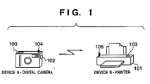
- FIG. 1 is a diagram showing an example of a configuration of a wireless LAN according to a first embodiment.
- wireless communication device A is a digital camera 100 having an IEEE802.11 compliant wireless communication function 104.
- the digital camera 100 becomes capable of configuring a network in communication parameter configuration mode when a user presses a communication parameter configuration activation button 102.
- wireless communication device B is a printer 101 having an IEEE802.11 compliant wireless communication function 105, and alike device A, becomes capable of configuring a network in communication parameter configuration mode when the user presses a communication parameter configuration activation button 103.
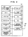
- FIG. 2 is a schematic block diagram of an example of a configuration of the digital camera 100 (device A).
- reference numeral 201 denotes a control unit that-controls the digital camera 100
- 202 denotes an image processing unit
- 203 denotes a ROM storing control instructions (programs) or control data
- 204 denotes a RAM.
- Configuration communication parameters for forming a communication parameter configuration network are stored in the RAM 204 in advance.
- 205 denotes a wireless communication processing unit, which performs communication control for the wireless LAN.
- 206 denotes an antenna
- 207 an antenna control unit.
- Reference numeral 208 denotes an image capturing unit that captures image signals inputted from a CCD 209.
- 210 denotes a card interface that controls a storage media card for storing captured images or configuration information, while 211 denotes a display unit.
- 212 denotes an operating unit, and includes buttons for issuing instructions on shooting, playback, configuration and the like.
- 213 denotes a power source unit that includes a secondary battery.
- 214 denotes a non-wireless communication interface, and comprises a wired interface such as USB or IEEE1394.
- 215 denotes a communication parameter configuration button that activates communication parameter configuration.
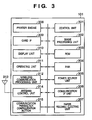
- FIG. 3 is a schematic block diagram of an example of a configuration of the printer 101 (device B).
- reference numeral 301 denotes a control unit for controlling the printer 101
- 302 denotes an image processing unit 302
- 303 denotes a ROM storing control instructions (programs) or control data
- 304 denotes a RAM
- 305 denotes a power source unit.
- Configuration communication parameters for forming a communication parameter configuration network are stored in the RAM 304 in advance.
- 306 denotes a non-wireless communication interface, and comprises a wired interface such as USB or IEEE1394.
- Reference numeral 307 denotes a paper feeding/ejecting unit that feeds and ejects printer paper.
- 308 denotes a printer engine that performs printing control using methods such as the electrophotographic method or the inkjet method.
- 309 denotes a card interface that controls a storage media card storing images, while 310 denotes a display unit.
- 311 denotes an operating unit that includes menu, configuration and other buttons.
- 312 denotes a wireless communication processing unit, which performs communication control for the wireless LAN.
- 313 denotes an antenna, and 314 an antenna control unit.
- 315 denotes a communication parameter configuration button that activates communication parameter configuration.
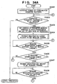
- FIG. 4 is a diagram showing a wireless parameter configuration sequence according to the first embodiment.
- the overall processing flow will be divided into six steps, as shown in FIG. 4 . Each step will now be explained in sequence.
- processing is performed for forming a communication parameter configuration network between devices A and B using ad hoc connection.
- processing for determining which of the devices A and B will become a master device of the communication parameter configuration network and which of the devices will become a slave device is performed.
- each device will continuously perform processing for monitoring whether the other party exists on the same network.
- the master device determined in step 402 performs processing for collecting device capability attribute values owned by slave devices existing on the same network by making inquiries to the slave devices.
- the master device compares its own device capability attribute values with those of each slave device collected by the master device in step 403.
- the master device determines which device will be the source of communication parameter transfer, and which device will be its destination.
- the master device also transfers information necessary for communication parameter transfer, such as destination or source information, to each slave device.
- communication parameters are transferred from a device that is actually capable of providing communication parameters to a device that is actually capable of receiving communication parameters along the communication parameter transfer direction determined in step 404.
- step 405 prompted by the completion of the transfer in step 405, processing necessary to terminate the communication parameter configuration network will be performed.
- a new network will be constructed using the communication parameters transferred in the communication parameter transfer step 405.
- the description will begin with the communication parameter configuration network formation step 401, carried out between the digital camera 100 and the printer 101.
- the communication parameter configuration activation button 215 of the digital camera 100 (apparatus A) and the parameter configuration activation button 315 of the printer 101 (apparatus B) are pressed.
- the buttons 215 and 315 are pressed, the digital camera 100 and the printer 101 form a communication parameter configuration ad hoc network.
- This network is formed using configuration communication parameters stored in the RAMs 204 and 304.
- messages transmitted and received between the various devices in the master device determination step 402 include at least the following information: address information indicating source and destination of transmission (destination MAC address 501, source MAC address 502), ID information 503 indicating an identifier (ID) for the communication parameter configuration control function, and expire time information indicating expire times for each device during the master device determination step 402.
- address information indicating source and destination of transmission (destination MAC address 501, source MAC address 502)
- ID information 503 indicating an identifier (ID) for the communication parameter configuration control function
- expire time information indicating expire times for each device during the master device determination step 402.
- an expire time information value of "0" indicates that the device transmitting the message will immediately detach itself from the network.
- FIGS. 6A , 6B and 6C are flowcharts showing master device/slave device determination processing performed by each device upon joining the network.
- step S601 the device activates a random timer T1.
- the timer T1 makes it possible to avoid message collisions that occur when messages are concurrently transmitted from a plurality of devices simultaneously initiating the master device determination step 402 by delaying the transmission of an inquiry message, performed during subsequent processing, by a random amount of time.
- step S602 the device verifies reception of a master declaration message that notifies the existence of a master device. If a master declaration message is received, it is determined that a master device already exists within the network, and the process proceeds to step S608 described later. If a master declaration message is not received, the device proceeds to step S603 to verify timeout of the timer T1. When the timer T1 has not yet timed out, the device returns to step S602, and repeats the abovementioned processing until either a master declaration message is received, or the timer T1 times out. This processing enables prompt processing upon master declaration reception, described in step S608, even when receiving the master declaration message during a random waiting time for the purpose of avoiding message collision.
- step S603 When the timer T1 times out in step S603, the process proceeds to step S604 during which the device broadcasts a master inquiry message that inquires about the existence of a master device, thereby activating master inquiry transmission timer T2.
- the master inquiry transmission timer T2 is used for transmitting a master inquiry message at regular intervals.
- step S605 the device verifies reception of the master declaration message.
- the device acknowledges that a master device already exists in the network, and proceeds to step S608 described later. If the master declaration message is not yet received, the device proceeds to step S606 to verify timeout of the timer T2. When the timer T2 has not yet timed out, the process returns to step S605, and repeats the abovementioned processing until either a master declaration message is received, or the timer T2 times out.
- step S606 the process proceeds to step S607 in which the device verifies whether the master inquiry message has been transmitted a predetermined number of times. If not, the process returns to step S604 and repeats the processing of steps S604 to S607 until either the master inquiry message has been transmitted a predetermined number of times or the master declaration message is received.
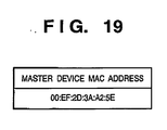
- step S608 a MAC address 501 of the master device is acquired from the received message.
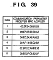
- the acquired MAC address is registered in a master device management table (see FIG. 19 ) stored in the RAM.
- the expire time of the master device is acquired from the received expire time information 504.
- a master device expire timer T7 is set to the acquired expire time and is activated. The timer T7 is used to verify the time that the master device exists on the network. When the timer T7 times out, the device determines that the master device has detached from the network.
- the device After activating the timer T7 in step S608, the device activates a random timer T9 in step S623.
- the timer T9 delays the transmission of a slave declaration message, performed during subsequent processing, by a random amount of time. This makes it possible to avoid message collisions that occur when slave declaration messages are concurrently transmitted from a plurality of devices in response to a master declaration message.
- the process proceeds to step S624 to wait for the timer T9 to time out.
- step S609 the device transmits a slave declaration message, which notifies that the device is a slave device, to the master device.
- step S610 the device activates a slave declaration message transmission timer T5.
- the timer T5 is used for periodic transmission of the slave declaration message, and the slave declaration message is retransmitted upon timeout of the timer T5.
- the timer T5 is set to a value that is shorter than the expire time described in the slave declaration message, enabling the timer T5 to periodically transmit the message while avoiding expiration.
- the device After activating the timer T5, the device performs operation as a slave device described later.
- step S607 When the master inquiry message is transmitted a predetermined number of times in the abovementioned step S607, the process proceeds to step S611 in which the device activates a master declaration message reception timer T3. The device waits for reception of a message from another device until the timer T3 times out. When a message is received, the device performs processing as described below according to the message type.
- step S612 the device verifies reception of the master declaration message.
- the process acknowledges that a master device already exists in the network and proceeds to step S608.
- the process proceeds to step S613.
- step S613 the device verifies reception of a master inquiry message.
- the device determines that a state of master inquiry collision exists, where a master device does not exist while devices other than the device itself that are capable of becoming the master device exist in the network.
- the process proceeds to step S614 to perform master collision resolution. Meanwhile, when a master inquiry message has not been received, the process proceeds to step S615.
- step S614 the device performs master collision resolution processing to resolve the state of master inquiry collision. This involves comparing the transmission source MAC address 502 of the received master inquiry message to the MAC address of the device in question in lexicographic order. When the comparison reveals that the MAC address of the device is smaller in lexicographic order, the device is determined to be a winner. On the other hand, when the comparison reveals that the MAC address of the device is larger in lexicographic order, the device is determined to be a loser. Determination results are stored to be used in the processing of step S617 to be described in detail later.
- each device performs the master collision resolution processing described in step 614 with a plurality of devices until the master declaration reception timer T3 times out.
- a loser determination will be stored as the determination result even when determined a loser only once.
- a winner determination will be stored as the determination result only when a device is determined to be a winner in all master collision resolution processing.
- step S615 the device verifies timeout of the master declaration reception timer T3.
- the device determines that no master devices exist in the network, and the process proceeds to step S616.
- the process returns to step S612.
- step S616 the device verifies whether master collision resolution processing has been performed by the time the master declaration reception timer T3 times out. If master collision resolution processing has been performed, the process proceeds to step S617, otherwise the process proceeds to step S618.
- step S617 the device verifies the determination results of the master collision resolution processing. If the determination resulted in a winner determination, the process proceeds to step S618. If the determination resulted in a loser determination, the process proceeds to step S620.
- step S618 the device broadcasts a master declaration message that notifies that the device itself is a master device to the network.
- step S619 the device activates a master declaration message transmission timer T4.
- the timer T4 is used to periodically transmit the master declaration message, and retransmits the master declaration message upon timeout.
- the timer T4 is set to a value that is shorter than the expire time described in the master declaration message, enabling the timer T4 to periodically transmit the message while avoiding expiration.
- the device After activating the timer T4, the device performs operation as a master device described later.
- step S620 the device activates a master declaration reception waiting timer T8.
- the timer T8 is used by the device that was determined to be the loser in the above described determination of step S617 to wait for a certain period for the reception of the master declaration message from the device that was determined to be the winner.
- step S621 the device verifies reception of the master declaration message. If the master declaration message was received, the process proceeds to step S608 described above. If the master declaration message was not received, the process proceeds to step S622. In step S622, the device verifies timeout of the master declaration reception waiting timer T8. If the timer T8 has timed out, the device performs error termination since it was unable to receive a message from the master device within the allotted time. On the other hand, if the timer T8 has not timed out, the process returns to step S621.
- the process may be configured to return to step S601 to retransmit the master inquiry message when the timer T8 times out.
- This processing enables prompt retrying of the processing of master and slave device determination even when the device was unable to receive a message from the master device within the allotted time.
- step S614 when a master inquiry message is received from another device before the transmission of a master inquiry message of step S604 is completed, the master collision resolution processing of step S614 is performed. If the master collision resolution processing results in a determination of loser, subsequent transmission of a master inquiry message is not necessary. This makes it possible to suppress transmission of unnecessary messages to the network.
- the master device performs processing described below according to various conditions when either receiving a message from another device on the network or when a timer within the master device times out.
- FIG. 7 is a flowchart showing response processing to a master inquiry message.
- the master device After initiating processing, in step S701, the master device transmits a master declaration message to the device that is the transmission source of the master inquiry message. After transmitting the message, the master device terminates master inquiry message response processing.
- step S701 when transmitting a master declaration message.as a response to a master inquiry message, a method where the master declaration message is broadcasted can be considered as an alternative to performing a unicast transmission to the source device of the message. While an advantage of the latter method is that economic message transmission is achieved, the former method is capable of transmitting a master declaration message to a plurality of devices at the same time, and thereby has an advantage where the master declaration message can be efficiently transmitted when a plurality of devices are in a state of master inquiry. Thus, the two methods have different advantages.
- the present invention does not limit the method to be used to transmit a master declaration message in response to a master inquiry message, and allows either method to be used.
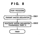
- FIG. 8 is a flowchart showing processing of master declaration message regular transmission.
- the master device After initiating processing, in step S801, the master device broadcasts a master declaration message to the network. After broadcasting the message, in step S802, the master device configures the master declaration message transmission timer T4 to a value that is shorter than the expire time of the master device, and restarts the timer T4. After restarting the timer, the master device terminates processing of master declaration message regular transmission.
- FIG. 9 is a flowchart showing slave device management processing.
- the master device After initiating processing, in step S901, the master device references the value described in the expire time information 504 of the slave declaration message to verify whether the value is "0". If the value of the expire time is "0", the master device determines that the slave device transmitting the slave declaration message will detach from the network, and the process proceeds to step S902. If the value of the expire time is not "0", the process proceeds to step S903.
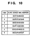
- step S903 the master device verifies whether the source MAC address 502 of the received slave declaration message is registered in the slave device management table (see FIG. 10 ) stored in the RAM.
- the slave device management table shown in FIG. 10 is a table for registering MAC addresses of slave devices according to index numbers for a master device to acquire information on slave devices currently participating in the network.
- the master device determines that the slave device that transmitted the slave declaration message has joined the network, and the process proceeds to step S904. If the source MAC address is registered in the table, the process proceeds to step S905 where the master device performs updating of the expire time of the slave device.
- step S904 the master device registers the source MAC address 502 of the received slave declaration message into the slave device management table.
- the master device sets a slave device expire timer T6n, which corresponds to an index number n for the registered slave device in the table, to the expire time referenced in the abovementioned step S901, and activates the timer.
- One timer T6 is activated for each slave device registered in the slave device management table.
- the master device determines that the corresponding slave device has detached from the network.
- step S905 the master device updates the timer value of the slave device expire timer T6n, which corresponds to the slave device that transmitted the slave device declaration message, to the expire time referenced in the abovementioned step S901, and restarts the timer.
- step S902 the master device deletes the MAC address of the slave device of the index number n, which corresponds to the slave device that transmitted the slave device declaration message, from the slave device management table.
- Slave device management by the master device is performed according to the above procedures.
- FIG. 11 is a flowchart showing processing upon detachment of a slave device.
- the master device determines that the slave device corresponding to the timed out timer has detached the network.
- the master device deletes the MAC address of the slave device of the index number n, which corresponds to the timer that has timed out, from the slave device management table. After deletion, the master device terminates the slave device detachment processing.
- master device termination processing performed by the master device as a normal termination of its operations as a master device in response to user operations or instructions from upper layer applications and the like, will be explained.
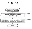
- FIG. 12 is a flowchart showing a process upon termination of a master device.
- the master device After initiating processing, in step S1201, the master device broadcasts a master declaration message with a value of "0" in its expire time information 504. This message broadcast serves to notify the slave device that the master device is about to detach.
- slave device expire timers T6 After transmitting the message, in step S1202, slave device expire timers T6 are terminated.
- regular transmission of the master declaration message is completed by discarding the slave device management table and terminating the master declaration message transmission timer T4. The operations of the master device are thereby completed.
- Operation of the master device in the master device determination step 402 is performed according to the procedures described above.
- step S604 device joining a network transmit master inquiry messages (step S604), and verify reception of master declaration messages (step S605). Meanwhile, a master device transmits master declaration messages immediately upon receiving master inquiry messages (step S701).
- device management processing using the abovementioned expire time information 504 enables devices to detect the detachment of devices by receiving messages where the expire times are set to "0", which allows the devices to understand the statuses of devices more promptly than in the case where verification is performed at regular intervals.
- the slave device performs processing described below according to various conditions when either receiving a message from the master device or when a timer within the slave device times out.
- FIG. 13 is a flowchart showing slave declaration message regular transmission processing.
- the slave device After initiating processing, in step S1301, the slave device transmits a slave declaration message to the master device. After transmitting the message, in step S1302, the slave device sets the slave declaration message transmission timer T5 to a value that is shorter than the expire time of the slave device, and restarts the timer. After restarting the timer, the slave device terminates processing for slave declaration message regular transmission.
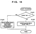
- FIG. 14 is a flowchart showing master device management processing.
- the slave device After initiating processing, in step S1401, the slave device references the value described in the expire time information 504 in the master declaration message to verify whether the value of the expire time is "0". If so, the slave device determines that the master device will detach from the network and proceeds to step S1403. If not, the process proceeds to step S1402.
- step S1402 the slave device updates the timer value of the master device expire timer T7 to the expire time referenced in the abovementioned step S1401, and restarts the timer.
- step S1403 the slave device terminates the master device expire timer T7 and discards the master device management table.
- the slave device terminates regular transmission of the slave declaration message, thereby terminating its operations as a slave device.
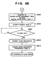
- FIG. 15 is a flowchart showing processing upon detachment of a master device.
- the slave device terminates the master device expire timer T7 and discards the master device management table.
- the slave device terminates regular transmission of the slave declaration message, thereby terminating its operations as a slave device.
- slave device termination processing performed by the slave device as a normal termination of its operations as a slave device in response to user operations or instructions from upper layer applications and the like, will be explained.
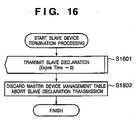
- FIG. 16 is a flowchart showing processing upon termination of a slave device.
- the slave device After initiating processing, in step S1601, the slave device transmits a slave declaration message with a value of "0" in its expire time information 504. The message transmission serves to notify the master device that the slave device is about to detach.
- the master device After transmitting the message, in step S1602, the master device expire timer T7 is terminated, and the master device management table is discarded.
- the slave device terminates regular transmission of the slave declaration message, thereby terminating its operation as a slave device.
- the abovementioned steps S1403 and S1501 may be configured so that the device retries the master device/slave device determination processing shown in FIGS. 6A , 6B and 6C after terminating operations as a slave device. For instance, even in the case where a master device terminates while performing wireless parameter auto-configuration between three or more devices, this makes it possible for the remaining devices to promptly recommence the master device determination step 402 to continue processing for wireless parameter auto-configuration.
- Operations for a slave device in the master device determination step 402 are performed according to the above procedures.
- the device B initiates processing after the device A initiates processing, and master and slave device are determined between the two devices.
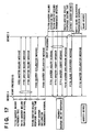
- FIG. 17 is a diagram showing a sequence for determining a master device and a slave device when the device B initiates processing after the device A initiates processing.
- the random timer T1 is activated over a master inquiry activation time (TH1700) to wait for message transmission (comparable to steps S601, S602 and S603). As explained above for step S601, this is performed to avoid message collisions that occur when messages are concurrently transmitted from a plurality of devices initiating the master device determination step 402 at the same time.
- the device A sets the master inquiry transmission timer T2 to a master inquiry transmission interval (TH1701) and activates the timer.
- the device A transmits a master inquiry message upon each timeout of the master inquiry transmission timer T2 (comparable to steps S604, S605, S606 and 5607).
- the master inquiry message is transmitted three times (F1702, F1703 and F1704).
- the device A After transmitting the master inquiry message, the device A activates the master declaration reception timer T3, and waits for a master inquiry response waiting time (TH1705) to receive a master declaration message (comparable to steps S611, S612, S613 and S615). In this example, the device A does not receive the message within the predetermined amount of time (TH1705). Therefore, after the timeout of the master declaration reception timer T3, the device A broadcasts (F1706) a master declaration message to notify other devices that the device A is the master device (comparable to steps S616 and S618).
- TH1705 master inquiry response waiting time
- the device A does not receive the message within the predetermined amount of time (TH1705). Therefore, after the timeout of the master declaration reception timer T3, the device A broadcasts (F1706) a master declaration message to notify other devices that the device A is the master device (comparable to steps S616 and S618).
- the device A After transmitting the master declaration message, the device A sets the master declaration transmission timer T4 to a master declaration transmission interval (TH1707) and activates the timer.
- the device A periodically broadcasts (F1708) the master declaration message every time the master declaration transmission timer T4 times out (comparable to steps S619, S801 and S802).
- processing of device B commences after regular transmission of the master declaration message is initiated (between F1706 and F1708) by the device A.
- the random timer T1 is activated over a master inquiry activation time (TH1709) to wait for message transmission.
- the device B sets the master inquiry transmission timer T2 to a master inquiry transmission interval (TH1710) and activates the timer.
- the device B transmits a master inquiry message three times (F1711, F1712 and F1713) upon each timeout of the master inquiry transmission timer T2.
- step S701 This allows the device A to respond to the master inquiry message (F1711) from the device B to transmit a master declaration message to the device B (F1714) (comparable to the processing of step S701).
- the device B activates the master declaration reception timer, and waits for the transmission of a master declaration message for a master inquiry response waiting time (TH1715).
- the device B detects that the device A is the master device by receiving a master declaration message from the device A during a predetermined time (TH1715).
- the device B registers the MAC address of the device A into the master device management table ( FIG. 19 ), and sets the master device expire timer T7 to the expire time of the device A acquired from the master declaration message and activates the timer.
- the device B transmits a slave declaration message (F1716) to the device A (comparable to steps S608 and S609).
- the device A when receiving the slave declaration message of device B, the device A registers the MAC address of the device B into the slave device management table ( FIG. 10 ). The device B also sets the slave device expire timer T6 to the expire time of the device B acquired from the slave declaration message and activates the timer (comparable to steps S901, S903 and S904).
- the device B After transmitting the slave declaration message, the device B sets the slave declaration transmission timer T5 to a slave declaration transmission interval (TH1717) and activates the timer. The device B periodically transmits (F1718) the slave declaration message to the device A every time the slave declaration transmission timer T5 times out (comparable to steps S610, S1301 and S1302).
- the devices A and B periodically transmit declaration messages according to the declaration transmission timers, and when declaration messages are received, reset the expire timers to the expire times in the messages and restart the expire timers (comparable to steps S905 and S1402).
- Master and slave devices are determined by the above procedures according to the sequence shown in FIG. 17 .
- this example assumes that the MAC address of the device A is smaller in lexicographic order than that of the device B, and that the device A will be determined to be the winner upon processing of master collision resolution.
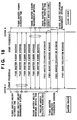
- FIG. 18 is a diagram showing a sequence for determining a master device and a slave device when the devices A and B initiate processing almost at the same time.
- the device A After initiating processing, the device A activates the random timer T1 over a master inquiry activation time (TH1800) to wait for message transmission.
- the device A sets the master inquiry transmission timer T2 to a master inquiry transmission interval (TH1801) and activates the timer.
- the device A transmits a master inquiry message upon each timeout of the master inquiry transmission timer T2.
- the master inquiry message is transmitted three times (F1802, F1803 and F1804).
- the device B activates the random timer T1 over a master inquiry activation time (TH1805) to wait for message transmission.
- the device B sets the master inquiry transmission timer T2 to a master inquiry transmission interval (TH1806) and activates the timer.
- the device B transmits a master inquiry message three times upon each timeout of the master inquiry transmission timer T2 (F1807, F1808 and F1809).
- the device A After transmitting the master inquiry message, the device A activates the master declaration reception timer T3, and waits to receive a message for a master inquiry response waiting time (TH1810).
- the device A performs master collision resolution processing since it receives a master inquiry message from the device B during a predetermined amount of time (TH1810) (S613 and S614). In this case, the device A will be determined as the winner by master collision resolution processing.
- the device A acknowledges that it has been determined as the winner by master collision resolution processing (comparable to step S617).
- the device A notifies the device B that it is the master device by broadcasting a master declaration message (F1812).
- the device A After transmitting the master declaration message, the device A sets the master declaration transmission timer T4 to a master declaration transmission interval (TH1813) and activates the timer. The device A periodically broadcasts (F1816) the master declaration message every time the master declaration transmission timer T4 times out.
- the device B after transmitting the master inquiry message, the device B also activates the master declaration reception timer T3, and waits to receive a message for a master inquiry response waiting time (TH1811).
- the device B detects that the device A is the master device since it receives the master declaration message from the device A during the predetermined time (TH1811).
- the device B registers the MAC address of the device A into the master device management table ( FIG. 19 ).
- the device B also sets the master device expire timer T7 to the expire time of the device A acquired from the master declaration message and activates the timer, and transmits (F1814) a slave declaration message to the device A.
- the device A When the device A receives the slave declaration message from device B, the device A registers the MAC address of the device B into the slave device management table ( FIG. 10 ). The device A also sets the slave device expire timer T6 to the expire time of the device B acquired from the slave declaration message and activates the timer.
- the device B After transmitting the slave declaration message, the device B sets the slave declaration transmission timer T5 to a slave declaration transmission interval (TH1815) and activates the timer. The device B periodically transmits (F1817) the slave declaration message every time the slave declaration transmission timer T5 times out.
- the device A and B periodically transmit declaration messages according to the declaration transmission timers, and when declaration messages are received, reset the expire timers to expire times in the messages and restart the expire timers.
- Master and slave device are determined by the above procedures according to the sequence shown in FIG. 18 .
- the device capability information collection step where the master device determined by the abovementioned master device determination step 402 collects device capability information from slave devices participating in the same network will be explained.
- FIG. 20 is a diagram showing a sequence of collection of information on device capability by a master device, the digital camera 100 (device A), from a slave device, the printer 101 (device B). A detailed description will be provided below.
- the digital camera 100 which is the master device, performs a device capability information collection request towards the printer 101 (F2001).
- the printer 101 which is the slave device, responds to this request by returning a device capability information collection response that includes its own device capability attribute value data to the source of request, the digital camera 100 (F2002).
- the master device activates a device capability information collection step timer TCM100, and performs the above described device capability information collection on slave devices currently considered to exist.
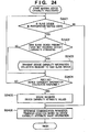
- FIG. 24 is a flowchart showing processing performed by the master device that corresponds to automatic communication parameter configuration during a device capability information collection step that includes determination processing. A detailed description will be provided below.
- the master device checks whether the current state is a slave device participation acceptance state (S2401). If the participation acceptance state has already been closed, collection of the device capability attribute values of devices already participating in the network has been completed. Thus, the process proceeds to the next step, which is the communication parameter transfer direction determination step 404 (S2406).
- the master device checks whether there are new slave devices (slave devices for which device capability attributes have not yet been collected) (S2402). If such a device exists, the master device transmits a device capability information collection request towards the new slave device (S2403). Upon receiving a device capability information collection response from the slave device (S2404), the master device stores the received device capability attribute values (S2405).
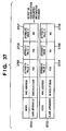
- FIG. 37 is a diagram showing an example of a configuration of a memory that stores device capability attribute values.
- the master device stores a table 3701 of its own attribute values, as well as a list 3702 of attribute values received from the new slave device.
- these are composed of lists containing MAC addresses to identify the devices and a plurality of attribute values (attribute values 1, 2 and 3).
- the transfer direction of the communication parameters will now be determined (S2406).
- the master device and the slave device both have the same value "YES" for attribute value 1.
- the master device has a value of "YES”
- the slave device has a value of "NO”. Therefore, the master device chooses itself as the communication parameter information provider.
- the master device is constantly capable of detecting slave devices while concurrently performing, as an independent process, collection of device capability attribute values from the slave devices. Therefore, it is possible of reducing the time required for processing as compared to a case when device capability attribute values of the slave devices are collected after closing the participation acceptance state.
- FIG. 22 is a flowchart showing processing performed by a slave device that corresponds to automatic communication parameter configuration during a device capability information collection step. A detailed description will be provided below.
- the device When the device is a slave device, it receives a device capability information collection request from the master device (S2201). The slave device transmits a device capability information collection response including information indicating its own device capability to the master device (S2202).
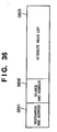
- FIG. 36 is a flowchart showing a message format transmitted and received by a device that corresponds to automatic communication parameter configuration during a device capability information collection step.
- the master device inserts the MAC address of the slave device that is the destination of the device capability information collection request to a destination MAC address 3601.
- the master device also inserts its own MAC address to a source MAC address 3602, and generates a message including a list of its own attribute values.
- the master device inserts the list into an attribute list 3603.
- the slave device responds to the reception of the device capability information collection request command from the master device by inserting the MAC address of the master device to the destination MAC address 3601.
- the slave device also inserts its own MAC address to the source MAC address 3602, and as was the case with the master device, inserts its own device capability attribute values to the attribute list 3603, and transmits the message as a response to the master device.
- both devices are now capable of mutually understanding the device capability of the other device.
- the slave device determines that the attribute value contained in the device capability information collection request message from the master device is not consistent with its own device capability attribute value, the slave device is capable of immediately terminating automatic communication parameter configuration instead of returning its device capability attribute value response. This enables prompt notification of the results of processing for automatic communication parameter configuration to the user.
- FIG. 32 is a flowchart showing communication parameter transfer direction determination processing.
- the digital camera 100 which is the master device, collects device capability attribute values of the printer 101, which is the slave device (S3201), and stores a device capability attribute value table in the RAM 204 in the format 3702 shown in FIG. 37 (S3202).
- the master device checks whether verification of all the attribute values of all the slave devices in the device capability attribute value table has been completed (S3203). If not, the master device extracts (screens and retains) all devices with "YES" as their current attribute values in the device capability attribute value table that stores the device capability attribute values of master and slave devices (S3204). Next, the master device checks whether the number of extracted devices (the number of devices screened and retained) is one or not (S3205).
- the master device advances the attribute value currently compared to the attribute value to be compared next (S3206), and repeats the above described processing (S3203). If verification of all attribute values has been completed and the number of extracted devices is one (S3207), the master device sets the extracted device as the parameter provider (S3208). In addition, if a plurality of extracted devices exists, the master device notifies that the transfer direction determination has resulted in an error (S3209).
- a configuration may be realized where the parameter provider is determined to be one device by comparing an attribute value list composed of a plurality of attribute values.
- a communication parameter provider can be chosen from all the devices that configure the communication parameter configuration network, regardless of whether the devices are master devices or slave devices.
- a communication parameter exchange sequence that is performed in the communication parameter transfer direction determination step 404 between the communication parameter provider and a receiver will now be explained.
- FIG. 26 is a diagram showing a sequence of providing communication parameters from the master device, the communication parameter provider, to the slave device, the receiver.
- the digital camera 100 transmits a "parameter transfer direction receiver request" message to the printer 101 (F2601).
- the printer 101 which has become a communication parameter receiver, returns a "parameter transfer direction receiver response” as a response to the digital camera 100 (F2602).
- Communication parameter exchange processing is performed from the digital camera 100 to the printer 101 (details will be provided later).
- the digital camera 100 transmits a "parameter transfer direction receiver completion request", which indicates the completion of the processing, to the printer 101 (F2603).
- the printer 101 returns a "parameter transfer direction receiver completion response” message as a response to the digital camera 100 (F2604).
- the digital camera 100 which has become the communication parameter provider, notifies the printer 101, which has become the communication parameter receiver, its own MAC address. After receiving the address, the printer 101 stores the communication parameters transmitted from the communication parameter provider into the RAM 304 or the like.
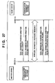
- FIG. 27 is a diagram showing a sequence of receiving communication parameters at the master device, the communication parameter receiver, from the slave device, the communication parameter provider.
- the digital camera 100 transmits a "parameter transfer direction provider request" message to the printer 101 (F2701).
- the printer 101 which has become the communication parameter provider, returns a "parameter transfer direction provider response” as a response to the digital camera 100 (F2702).
- Communication parameter exchange processing is performed from the printer 101 to the digital camera 100 (details will be provided later).
- the printer 101 transmits a "parameter transfer direction provider completion request", which indicates the completion of the processing, to the digital camera 100 (F2703).
- the digital camera 100 returns a "parameter transfer direction provider completion response” message as a response to the printer 101 (F2704).
- the digital camera 100 which has become the communication parameter receiver, notifies the printer 101, which has become the communication parameter provider, its own MAC address. After receiving the address, the printer 101 transmits the communication parameters to the digital camera 100, which has become the communication parameter receiver. The digital camera 100 stores the communication parameters transmitted from the printer 101 into the RAM 204.
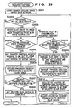
- FIG. 29 is a flowchart showing master device transfer direction determination processing.
- the device A which is the master device, verifies the number of slave devices existing on the same network (S2901).
- the master device checks whether processing with all slave devices has been concluded (S2902). If not, the master device selects slave devices that have not yet received notification of the parameter transfer direction from those on the slave device address list (S2903).
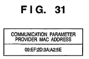
- the master device checks whether the master'device itself has become the communication parameter provider (S2904). If so, the master device sets the transfer direction request message to be sent to the slave device selected in step S2903 to the MAC address of the master device, which has become the parameter provider, as shown in FIG. 31 (S2905).
- the master device transmits a message indicating a parameter transfer direction receiver request to the selected slave device (S2906).
- the master device next waits for reception of a parameter transfer direction receiver response message from the selected slave device (S2907). After reception thereof, the master device sets the selected slave device to transfer direction notification completion (S2908), and returns to step S2902 to repeat the above described processing until all slave devices have been processed.
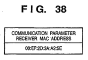
- the master device checks whether the selected slave device is the communication parameter provider (S2909). In the event that the selected slave device is the communication parameter provider, the master device configures the transfer direction request message to be transmitted to the slave device to the MAC address of the master device itself, which has become a parameter receiver, as shown FIG. 38 , as well as the MAC addresses of other slave devices if such slave devices exist (S2910). The master device transmits a message indicating a parameter transfer direction provider request to the selected slave device (S2911).
- the master device waits for reception of a parameter transfer direction provider response from the selected slave device (S2907). After reception, the master device sets the selected slave device to transfer direction notification completion (S2908), and returns to step S2902 to repeat the above described processing until all slave device have been processed.
- the transfer direction request message to be sent to the selected slave device is set to the MAC address of the slave device that has become the parameter provider (S2912).
- a message indicating a parameter transfer direction receiver request is transmitted to the selected slave device (S2913).
- the master device waits for reception of a parameter transfer direction receiver response from the selected slave device (S2907). After reception, the master device sets the selected slave device to transfer direction notification completion (S2908), and returns to step S2902 to repeat the above described processing until all slave devices have been processed.
- a slave device determines whether a device corresponding to automatic communication parameter configuration is a communication parameter provider or a communication parameter receiver.
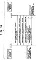
- FIG. 30 is a flowchart showing slave device transfer direction determination processing.
- the slave device first checks reception of a communication parameter transfer direction request message from the master device (S3001). After receiving the message, the slave device transmits a communication parameter transfer direction response message to the master device (S3002). At this point, if the role of the transfer direction request from the master device is that of a communication parameter provider (YES in S3003), the slave device stores the list of MAC addresses of the communication parameter receivers included in the communication parameter transfer direction request message (S3004). In addition, if the role of the transfer direction request from the master device is that of a communication parameter receiver (NO in S3003), the slave device stores the MAC address of the communication parameter provider included in the communication parameter transfer direction request (S3005).
- FIG. 33 is a diagram showing a sequence for transmitting and receiving communication parameter data between a communication parameter provider and a receiver.
- the digital camera 100 will act as the communication parameter provider, while the printer 101 will act as a receiver.
- the digital camera 100 which has become the communication parameter provider, requests input of an identification number to the printer 101 prior to the transmitting and receiving of communication parameters (F3301).
- the printer 101 In response to the request for an identification number, the printer 101 returns data that includes the value of its identification number (F3302).
- an encryption key configuration request message is sent from the digital camera 100 to the printer 101 (F3303). After receiving the message, the printer 101 returns an encryption key configuration response to the digital camera 100 (F3304).
- the digital camera 100 transmits communication parameter data to the printer 101.
- the digital camera 100 encrypts the communication parameter data with the encryption key.
- a continue signal that indicates continuation of data is attached to the transmitted data (F3305).
- the printer 101 returns a further request in the event that the data request processing results in a continue signal, and a response signal indicating the termination of data transmission in the event of an OK status, to the digital camera 100 (F3306).
- the printer 101 decrypts the completely received communication parameter data with the above encryption key, and stores the decrypted communication parameter data.
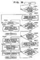
- FIGS. 34A and 34B are flowcharts showing processing at a device providing communication parameters.
- the digital camera 100 which is the communication parameter provider, configures and stores the number of communication parameter receivers, to which it must transfer communication parameter information, to the RAM 204 of the digital camera 100 (S3401).
- the digital camera 100 checks whether transmission of communication parameters to all the devices that will become communication parameter receivers has been concluded (S3402). If so, normal termination is processed. Otherwise, the following processing is repeated.
- the address of a parameter receiver device that has not yet received the communication parameters is configured as a destination address (S3403).
- identification number request messages are transmitted to the parameter receiver device indicated by the configured destination address (S3404).
- the digital camera waits to receive an identification number response message from the parameter receiver device (S3405). Upon reception, the digital camera checks whether the identification number included in the identification number response message is correct (S3406).
- the digital camera proceeds to transmit an encryption key request message to the parameter receiver device (S3407), and waits to receive an encryption key response message from the parameter receiver device (S3408). Upon reception, the digital camera uses the encryption key transmitted as the encryption key response message to encrypt the communication parameter information to be transmitted (S3409). The encrypted communication parameter information is transmitted to the parameter receiver device (S3410). The digital camera waits to receive a communication parameter information response message from the receiver device (S3411). Upon reception, the digital camera proceeds to the processing for selecting the next parameter receiver device (S3412).
- the digital camera determines that the identification number included in the identification number response message received from the parameter receiver device is not correct (NO in S3406), the digital camera transmits an identification number re-request to the parameter receiver device (S3413). If a refusal message is received as a response to the identification number re-request (YES in S3414), an error termination is processed. Meanwhile, if an identification number response message is received (YES in S3405) instead of a refusal message to the identification number request, the above described processing is repeated.
- FIG. 35 is a flowchart showing processing at a device receiving communication parameters.
- the printer 101 which is a communication parameter receiver, waits to receive an identification number request message from the digital camera 100, which is the communication parameter provider (S3501).
- the printer 101 performs displaying to prompt the user to input an identification number at the operating unit 311, and transmits the identification number inputted by the user as an identification number response message to the communication parameter provider device (S3502).
- an identification number re-request message is received from the communication parameter provider device (YES in S3503), since it is possible that the identification number had been erroneously inputted, the printer 101 displays an inquiry as to whether processing should be aborted to the display unit 310 of the printer 101. If a cancel instruction or the like indicating that operations should be aborted is inputted via the operating unit 311 (YES in S3504), the printer 101 transmits an identification number request refusal message to the digital camera 100, and an error termination is processed (S3505).
- the printer 101 waits to receive an encryption key request to be transmitted by the communication parameter provider device (S3506), and transmits an encryption key as a response to the digital camera 100, which is the communication parameter provider (S3507).
- the printer 101 waits to receive a communication parameter request message from the communication parameter provider device (S3508).
- the printer 101 transmits a communication parameter response message to the communication parameter provider device (S3509)
- the printer 101 decrypts the communication parameter request message with the encryption key to acquire the communication parameters (S3510).
- the communication parameters are stored to process normal termination (S3511).
- each device After storing the communication parameter information in step S3511, by configuring the communication parameters as the communication parameters for a new network, each device will exit the communication parameter configuration network to form the new network.
- FIG. 40 is a diagram showing an example of a configuration of a wireless LAN according to the second embodiment.
- wireless communication devices A, B and C are respectively a digital camera 100, a printer 101 and a digital camera 106.
- Wireless communication parameter configuration for ad hoc communication is to be performed among these three devices.
- the digital camera 100 is wireless LAN-capable through its wireless communication function 104, and is able to configure a network in communication parameter configuration mode when a user presses a communication parameter configuration activation button 102.
- the printer 101 also is wireless LAN-capable through its wireless communication function 105, and is able to configure a network in communication parameter configuration mode when a user presses a communication parameter configuration activation button 103.
- the digital camera 106 also is wireless LAN-capable through its wireless communication function 108, and is able to configure a network in communication parameter configuration mode when a user presses a communication parameter configuration activation button 107.
- the configurations of the digital cameras 100 (device A), 106 (device C) and the printer 101 (device B) are the same as the configuration explained for the first embodiment using FIGS. 2 and 3 , and further description will be omitted here.
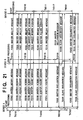
- FIG. 21 is a diagram showing a sequence for determining a master device and a slave device according to a second embodiment.
- the example shown in FIG. 21 illustrates a case where the device A first initiates processing, followed by device B, and finally by device C.
- this example assumes that the descending lexicographic order of the MAC addresses of the devices is: C, A and B.
- the device A After initiating processing, the device A activates a random timer over a master inquiry activation time (TH2100) to wait for message transmission.
- TH2100 master inquiry activation time
- the device A sets a master inquiry transmission timer to a master inquiry transmission interval (TH2101) and activates the timer.
- the device A transmits a master inquiry message upon each timeout of the master inquiry transmission timer.
- the master inquiry message is transmitted three times (F2102, F2103 and F2104).
- the device B After initiating processing, the device B activates a random timer over a master inquiry activation time (TH2105) to wait for message transmission.
- the device B sets a master inquiry transmission timer to a master inquiry transmission interval (TH2106) and activates the timer.
- the device B transmits a master inquiry message three times upon each timeout of the master inquiry transmission timer (F2107, F2108 and F2109).
- the device C After initiating processing, the device C activates a random timer over a master inquiry activation time (TH2110) to wait for message transmission.
- a master inquiry activation time TH2110
- the device C sets a master inquiry transmission timer to a master inquiry transmission interval (TH2111) and activates the timer.
- the device C transmits a master inquiry message three times upon each timeout of the master inquiry transmission timer (F2112, F2113 and F2114).
- the device A After transmitting the master inquiry message, the device A next activates a master declaration reception timer, and waits to receive a message for a master inquiry response waiting time (TH2115). In this example, the device A performs master collision resolution processing twice since it receives master inquiry messages from the devices B and C during the predetermined amount of time (TH2115).
- the master collision resolution processing of the second embodiment will determine the device A to be a winner against the device B, and a loser against the device C. Therefore, after timeout of the master declaration reception timer, the device A activates a master declaration reception waiting timer, and waits for a predetermined amount of time (TH2118) for the transmission of the master declaration message (comparable to the processing of S820 shown in FIG. 8 ).
- the device B After transmitting the master inquiry message, the device B activates a master declaration reception timer, and waits to receive a message for a master inquiry response waiting time (TH2116). In this example, the device B performs master collision resolution processing since it receives a master inquiry message from the device C during the predetermined amount of time (TH2116).
- the master collision resolution processing of the second embodiment will determine the device B to be a loser against the device C. Therefore, after timeout of the master declaration reception timer, the device B activates a master declaration reception waiting timer, and waits for a predetermined amount of time (TH2119) for the transmission of the master declaration message.
- the device C activates a master declaration reception timer, and waits to receive a message for a master inquiry response waiting time (TH2117).
- TH2117 a master inquiry response waiting time
- the device C will not receive a master inquiry message during the predetermined amount of time (TH2117). Therefore, after timeout of the master declaration reception timer, the device C notifies the other device that it is the master device by broadcasting a master declaration message (F2120).
- the device C After transmitting the master declaration message, the device C sets the master declaration transmission timer to a master declaration transmission interval (TH2121) and activates the timer. The device C periodically broadcasts the master declaration message every time the master declaration transmission timer times out (F2122).
- the device B detects that the device C is the master device since it receives a master declaration message from the device C during the predetermined time (TH2119).
- the device B registers the MAC address of the device C into the master device management table.
- the device B also sets the master device expire timer to the expire time of the device C acquired from the master declaration message and activates the timer, and transmits a slave declaration message to the device C (F2123).
- the device B After transmitting the slave declaration message, the device B sets the slave declaration transmission timer to a slave declaration transmission interval (TH2124) and activates the timer. The device B periodically transmits the slave declaration message to the device C every time the slave declaration transmission timer times out (F2125).
- the device A detects that the device C is the master device since it receives a master declaration message from the device C during the predetermined time (TH2118).
- the device A registers the MAC address of the device C into the master device management table.
- the device A also sets the master device expire timer to the expire time of the device C acquired from the master declaration message and activates the timer, and transmits a slave declaration message to the device C (F2126).
- the device A After transmitting the slave declaration message, the device A sets the slave declaration transmission timer to a slave declaration transmission interval (TH2127) and activates the timer. The device A periodically transmits the slave declaration message to the device C every time the slave declaration transmission timer times out (F2128).
- master and slave devices are determined by the procedures described above.
- the device capability information collection step 403 of the second embodiment where the master device determined by the master device determination step 402, in the same way as in the first embodiment, collects device capability information from slave devices participating in the same network will be explained.
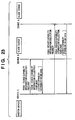
- FIG. 23 is a diagram showing a sequence of collection of information on device capability as a master device by the digital camera 106 (device C) from the printer 101 (device B) and the digital camera 100 (device A) as slave devices. A detailed description will be provided below.
- the digital camera 106 transmits a device capability information collection request towards the printer 101 (device B) (F2301).
- the printer 101 Upon receiving the request, the printer 101 returns a device capability information collection response that includes its own device capability attribute values (F2302).
- the digital camera 106 (device C) transmits a device capability information collection request towards the digital camera 100 (device A) (F2303).
- the digital camera 100 Upon receiving the request, the digital camera 100 returns a device capability information collection response that includes its own device capability attribute values (F2304).
- the digital camera 106 which is the master device, collects device capability attribute data of all slave devices currently existing on the same network.
- the master device performs collection, as a network administrator, of device capability attribute data of each slave device existing on the same network, prompt device capability information collection by the master device upon participation of a slave device at a given point in time, even when three or more devices exist on the same network, becomes possible.
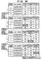
- FIG. 25 is a diagram showing a device capability attribute table after collection of device capability attributes from all devices on the same network by a master device. A description of how a communication parameter information provider is determined from these device capability attribute values will now be provided.
- the processing of the first embodiment for transfer direction determination of communication parameters may be applied for this determination processing.
- an eventual communication parameter information provider can be determined by performing sequential filtering using an attribute value list comprised of a plurality of attribute values.
- an attribute value list comprised of a plurality of attribute values.
- weighting the plurality of attribute values it becomes possible to select a device that has certain device capabilities as the communication parameter information provider.
- This processing is the same as that explained for the first embodiment using FIG. 29 .
- FIG. 28 is a diagram showing a transferring sequence of communication parameters according to the second embodiment. It is assumed that the digital camera 106 (device C), which is the master device, has determined through the earlier processing for determining the communication parameter provider that the digital camera 100 (device A), which is a slave device, will be a communication parameter receiver, and that the printer 101 (device B), which is a slave device, will be the communication parameter provider.
- the digital camera 106 (device C) transmits a "parameter transfer direction receiver request" message that includes an address of the communication parameter provider, as shown in FIG. 31 , to the digital camera 100 (device A) to request that it become a communication parameter receiver (F2801).
- the digital camera 100 returns a "parameter transfer direction receiver response" message to accept its appointment as a communication parameter receiver (F2802).
- the digital camera 106 (device C) transmits a "parameter transfer direction provider request" message that includes the addresses of all communication parameter receivers, as shown in FIG. 39 (six receiver devices are shown in FIG. 39 ), to the printer 101 (device B) to request that it become a communication parameter provider (F2803).
- the printer 101 returns a "parameter transfer direction provider response" message to accept its appointment as a communication parameter provider (F2804).
- the printer 101 performs a wireless parameter exchange sequence with the digital camera 100 (device A). After completion of the sequence, the digital camera 100 requests a "parameter transfer direction receiver completion request" message, which indicates the completion of the communication parameter receiver processing, to the digital camera 106 (device C), which is the master device (F2805). In response, the digital camera 106 returns a "parameter transfer direction receiver completion response" message (F2806).
- the digital camera 106 (device C) and the printer 101 (device B) also perform a wireless parameter exchange sequence. After completion of the sequence, the printer 101 requests a "parameter transfer direction provider completion request" message, which indicates the completion of the communication parameter provider processing, to the digital camera 106 (device C), which is the master device (F2807). In response, the digital camera 106 returns a "parameter transfer direction provider completion response" message (F2808).
- each device will exit the communication parameter configuration network to form the new network.
- the sequence of transmitting transfer direction requests to each slave device will commence with the master device transmitting communication parameter receiver response messages to each slave device that has become a communication parameter receiver.
- a sequencing rule will be applied to slave devices that have become communication parameter providers to transmit communication parameter provider request messages. This eliminates the need for the communication parameter provider to check whether each communication parameter receiver has already received a become communication parameter receiver message from the master device, even among a plurality of devices.
- processing may instantly proceed to a wireless parameter exchange sequence without having to consider the sequence of parameter receivers.
- wireless LAN was given as an example of wireless communication described in the first and second embodiments, the present invention may be applied to other wireless communication methods including Bluetooth (registered trademark), Wireless USB, Wireless 1394, UWB and WiMAX.
- the present invention may be applied to both systems comprising a plurality of devices (for example, a host computer, an interface device, a reader or a printer), and apparatuses composed of a single device (for example, a copying machine or facsimile machine).
- a plurality of devices for example, a host computer, an interface device, a reader or a printer
- apparatuses composed of a single device for example, a copying machine or facsimile machine.
- the object of the present invention may also be achieved by supplying a storage media that stores a program code of a software capable of achieving the functions of the described embodiments to a system or an apparatus, and having a computer (CPU or MPU) of the system or apparatus read out and execute the program stored in the storage media.
- a storage media that stores a program code of a software capable of achieving the functions of the described embodiments
- a computer CPU or MPU
- Storage devices to which the program codes can be supplied include, for instance, a floppy disk (registered trademark), a hard disk, an optical dick, a magneto-optical disk, a CD-ROM, a CD-R, a magnetic tape, a nonvolatile memory card, a ROM or the like.
- the functions of the aforementioned embodiments can also be achieved by writing program codes read out from a storage media into either a function enhancement board inserted into a computer or a memory built into a function enhancement unit connected to a computer, and having a CPU or the like built into the function enhancement board or the function enhancement unit perform a portion or all of the actual processing based on instructions from the program code.
- a network management apparatus for managing the network based on message information transmitted and received on the network is determined.
- the apparatus collects information indicating device capabilities from other communication apparatuses.
- the communication apparatus receives information indicating device capabilities from another communication apparatus when the other communication apparatus is determined as the network management apparatus.
Landscapes
- Engineering & Computer Science (AREA)
- Computer Networks & Wireless Communication (AREA)
- Signal Processing (AREA)
- Computer Security & Cryptography (AREA)
- Computing Systems (AREA)
- Databases & Information Systems (AREA)
- Health & Medical Sciences (AREA)
- General Health & Medical Sciences (AREA)
- Medical Informatics (AREA)
- Computer Hardware Design (AREA)
- General Engineering & Computer Science (AREA)
- Mobile Radio Communication Systems (AREA)
- Small-Scale Networks (AREA)
Applications Claiming Priority (1)
| Application Number | Priority Date | Filing Date | Title |
|---|---|---|---|
| JP2005130480A JP4900891B2 (ja) | 2005-04-27 | 2005-04-27 | 通信装置及び通信方法 |
Publications (2)
| Publication Number | Publication Date |
|---|---|
| EP1718013A1 EP1718013A1 (en) | 2006-11-02 |
| EP1718013B1 true EP1718013B1 (en) | 2009-07-29 |
Family
ID=36708546
Family Applications (1)
| Application Number | Title | Priority Date | Filing Date |
|---|---|---|---|
| EP20060113209 Ceased EP1718013B1 (en) | 2005-04-27 | 2006-04-27 | Communication apparatus and communication method |
Country Status (6)
| Country | Link |
|---|---|
| US (4) | US8572222B2 (enExample) |
| EP (1) | EP1718013B1 (enExample) |
| JP (1) | JP4900891B2 (enExample) |
| KR (1) | KR100815510B1 (enExample) |
| CN (1) | CN1855864A (enExample) |
| DE (1) | DE602006008061D1 (enExample) |
Families Citing this family (67)
| Publication number | Priority date | Publication date | Assignee | Title |
|---|---|---|---|---|
| JP4125173B2 (ja) | 2003-04-23 | 2008-07-30 | キヤノン株式会社 | 情報処理装置の接続制御方法、情報処理装置、及びコンピュータプログラム |
| JP4136771B2 (ja) | 2003-04-23 | 2008-08-20 | キヤノン株式会社 | 通信システム、通信装置、及びその制御方法、並びにコンピュータプログラム |
| JP4502389B2 (ja) * | 2005-03-15 | 2010-07-14 | キヤノン株式会社 | 通信装置及びその制御方法 |
| JP4366323B2 (ja) | 2005-03-15 | 2009-11-18 | キヤノン株式会社 | 通信装置およびその制御方法 |
| JP4356997B2 (ja) * | 2005-03-15 | 2009-11-04 | キヤノン株式会社 | 通信装置及びその通信方法 |
| JP4656637B2 (ja) * | 2005-04-27 | 2011-03-23 | キヤノン株式会社 | 通信装置及び通信システムとその通信パラメータ設定方法 |
| JP4900891B2 (ja) * | 2005-04-27 | 2012-03-21 | キヤノン株式会社 | 通信装置及び通信方法 |
| JP4250611B2 (ja) * | 2005-04-27 | 2009-04-08 | キヤノン株式会社 | 通信装置、通信パラメータ設定方法及び通信方法 |
| JP4006452B2 (ja) * | 2005-06-13 | 2007-11-14 | キヤノン株式会社 | 通信装置、通信方法及びその通信方法をコンピュータに実行させるためのコンピュータプログラム |
| JP4266962B2 (ja) * | 2005-06-16 | 2009-05-27 | キヤノン株式会社 | 通信装置、その制御方法及びプログラム |
| JP4886463B2 (ja) | 2006-10-20 | 2012-02-29 | キヤノン株式会社 | 通信パラメータ設定方法、通信装置及び通信パラメータを管理する管理装置 |
| JP4871696B2 (ja) | 2006-10-27 | 2012-02-08 | キヤノン株式会社 | 通信パラメータの設定処理方法、通信装置、通信装置の制御方法、プログラム |
| US8170183B2 (en) * | 2007-01-22 | 2012-05-01 | Control4 Corporation | Systems and methods for providing a message service for a site |
| JP4789817B2 (ja) | 2007-01-29 | 2011-10-12 | キヤノン株式会社 | 通信装置及び通信装置の通信方法、プログラム |
| JP4924082B2 (ja) * | 2007-02-19 | 2012-04-25 | 株式会社ナカヨ通信機 | 呼制御機能を有するipホン |
| CN100534037C (zh) * | 2007-10-30 | 2009-08-26 | 西安西电捷通无线网络通信有限公司 | 一种适用于ibss网络的接入认证方法 |
| JP5328141B2 (ja) * | 2007-12-05 | 2013-10-30 | キヤノン株式会社 | 通信装置、通信装置の制御方法、コンピュータプログラム |
| JP5328142B2 (ja) * | 2007-12-05 | 2013-10-30 | キヤノン株式会社 | 通信装置、通信装置の制御方法、コンピュータプログラム |
| JP4998305B2 (ja) * | 2008-02-13 | 2012-08-15 | 株式会社ナカヨ通信機 | ローカル通信機能を有する無線通信端末 |
| JP5129617B2 (ja) * | 2008-03-12 | 2013-01-30 | キヤノン株式会社 | 通信制御方法、通信システム、通信装置及びコンピュータプログラム |
| JP5270937B2 (ja) | 2008-03-17 | 2013-08-21 | キヤノン株式会社 | 通信装置及びその制御方法 |
| US7814182B2 (en) * | 2008-03-20 | 2010-10-12 | International Business Machines Corporation | Ethernet virtualization using automatic self-configuration of logic |
| JP5197109B2 (ja) * | 2008-04-04 | 2013-05-15 | キヤノン株式会社 | 通信装置、通信装置の通信方法、プログラム、記憶媒体 |
| JP5197110B2 (ja) * | 2008-04-04 | 2013-05-15 | キヤノン株式会社 | 通信装置、通信装置の通信方法、プログラム、記憶媒体 |
| JP5230249B2 (ja) * | 2008-04-24 | 2013-07-10 | キヤノン株式会社 | 通信装置、通信装置の制御方法、プログラム、記憶媒体 |
| JP5078736B2 (ja) * | 2008-04-28 | 2012-11-21 | キヤノン株式会社 | 通信装置、通信装置の通信方法、プログラム、記憶媒体 |
| JP5149715B2 (ja) * | 2008-06-30 | 2013-02-20 | キヤノン株式会社 | 通信システム、通信装置及びその制御方法、プログラム |
| JP5307508B2 (ja) | 2008-08-29 | 2013-10-02 | キヤノン株式会社 | 通信装置、通信方法、コンピュータプログラム |
| JP5222081B2 (ja) | 2008-09-24 | 2013-06-26 | キヤノン株式会社 | 通信装置、通信装置の制御方法、コンピュータプログラム、記憶媒体 |
| JP5127658B2 (ja) | 2008-10-06 | 2013-01-23 | キヤノン株式会社 | 通信装置、通信装置の制御方法、コンピュータプログラム及び記憶媒体 |
| JP5571892B2 (ja) | 2008-10-06 | 2014-08-13 | キヤノン株式会社 | 通信装置、通信方法、コンピュータプログラム、記憶媒体 |
| JP5121668B2 (ja) | 2008-10-22 | 2013-01-16 | キヤノン株式会社 | 通信装置、通信装置の制御方法、プログラム |
| JP5483985B2 (ja) | 2008-12-22 | 2014-05-07 | キヤノン株式会社 | 通信装置、通信装置の制御方法、プログラム、記憶媒体 |
| JP2010193935A (ja) | 2009-02-23 | 2010-09-09 | Konami Digital Entertainment Co Ltd | 端末装置、通信システム、端末方法、ならびに、プログラム |
| EP2253566B1 (de) | 2009-05-22 | 2013-07-31 | Müller Martini Holding AG | Vorrichtung zur Beschickung einer Verarbeitungsstrecke mit Druckprodukten |
| JP5295017B2 (ja) * | 2009-07-07 | 2013-09-18 | キヤノン株式会社 | 通信装置、通信装置の制御方法、プログラム |
| US20110154222A1 (en) * | 2009-12-18 | 2011-06-23 | Microsoft Corporation | Extensible mechanism for conveying feature capabilities in conversation systems |
| ES2782120T3 (es) * | 2010-01-14 | 2020-09-10 | France Brevets | Dispositivo electrónico y método de funcionamiento del mismo |
| JP5524026B2 (ja) * | 2010-11-15 | 2014-06-18 | 株式会社日立製作所 | エレメント端末および通信システム |
| US8983513B2 (en) * | 2010-11-30 | 2015-03-17 | Motorola Solutions, Inc. | Method and apparatus for sending a channel timing message in a digital mobile radio system |
| JP5618891B2 (ja) * | 2011-04-19 | 2014-11-05 | 三菱電機株式会社 | ネットワーク装置およびネットワークシステム |
| US9516615B2 (en) | 2011-11-18 | 2016-12-06 | Apple Inc. | Selection of synchronization stations in a peer-to-peer network environment |
| US9473574B2 (en) | 2011-11-18 | 2016-10-18 | Apple Inc. | Synchronization of devices in a peer-to-peer network environment |
| US10271293B2 (en) | 2011-11-18 | 2019-04-23 | Apple Inc. | Group formation within a synchronized hierarchy of peer-to-peer devices |
| JP6408753B2 (ja) | 2012-05-17 | 2018-10-17 | キヤノン株式会社 | 通信装置、通信装置の制御方法、プログラム |
| JP2014102691A (ja) * | 2012-11-20 | 2014-06-05 | Toshiba Corp | 情報処理装置、通信機能を持つカメラ、および情報処理方法 |
| JP6071624B2 (ja) * | 2013-02-22 | 2017-02-01 | キヤノン株式会社 | 通信装置、通信装置の制御方法、プログラム |
| KR20140124171A (ko) * | 2013-04-16 | 2014-10-24 | 삼성전자주식회사 | 디바이스들 간 동기화 장치 및 방법 |
| US9647779B2 (en) | 2013-04-22 | 2017-05-09 | The Nielsen Company (Us), Llc | Systems, methods, and apparatus to identify media devices |
| JP2014241513A (ja) | 2013-06-11 | 2014-12-25 | キヤノン株式会社 | 通信装置、通信装置の制御方法、及びプログラム |
| JP6317576B2 (ja) | 2013-11-29 | 2018-04-25 | キヤノン株式会社 | 通信装置、通信装置の制御方法およびプログラム |
| JP6183982B2 (ja) * | 2014-03-27 | 2017-08-23 | 株式会社日立国際電気 | 編成内ネットワークシステム、編成内ネットワーク管理方法、および管理装置 |
| US9729785B2 (en) * | 2015-01-19 | 2017-08-08 | Microsoft Technology Licensing, Llc | Profiles identifying camera capabilities that are usable concurrently |
| JP2016136364A (ja) | 2015-01-23 | 2016-07-28 | キヤノン株式会社 | 通信装置及びその制御方法、プログラム |
| JP6501597B2 (ja) * | 2015-04-09 | 2019-04-17 | キヤノン株式会社 | 通信装置、通信装置の制御方法、プログラム |
| WO2017113924A1 (en) * | 2015-12-31 | 2017-07-06 | Lam Cho Wing | System including alternation of sensor connection and transmission mechanism for motion sensing garment |
| JP6614983B2 (ja) * | 2016-01-26 | 2019-12-04 | キヤノン株式会社 | 通信装置、通信方法、プログラム |
| EP3433972B1 (en) * | 2016-03-23 | 2020-07-22 | Telefonaktiebolaget LM Ericsson (publ) | Cyber-physical context-dependent cryptography |
| CN105930200A (zh) * | 2016-04-19 | 2016-09-07 | 汉柏科技有限公司 | 基于精简配置的为虚拟机创建定时器的方法及装置 |
| US10505909B2 (en) * | 2016-12-21 | 2019-12-10 | Intel Corporation | Dual physical channel secure connection |
| KR101776172B1 (ko) * | 2017-02-14 | 2017-09-07 | 주식회사 유니온플레이스 | 사물 인터넷 장치 |
| US20190045483A1 (en) * | 2017-08-07 | 2019-02-07 | Apple Inc. | Methods for Device-to-Device Communication and Off Grid Radio Service |
| EP4114052B1 (en) * | 2019-07-26 | 2023-12-20 | Google LLC | Method for managing a plurality of multimedia communication links in a point-to-multipoint bluetooth network |
| US12301534B2 (en) | 2020-03-27 | 2025-05-13 | The Nielsen Company (Us), Llc | Methods and apparatus to facilitate device identification |
| CN111901304B (zh) * | 2020-06-28 | 2022-08-26 | 北京可信华泰信息技术有限公司 | 移动安全设备的注册方法和装置、存储介质、电子装置 |
| CN112180757B (zh) * | 2020-11-03 | 2022-10-25 | 哈尔滨工程大学 | 一种智能家居系统及其策略管理方法 |
| US12393579B2 (en) | 2021-12-31 | 2025-08-19 | The Nielsen Company (Us), Llc | Methods and apparatus to identify electronic devices |
Family Cites Families (241)
| Publication number | Priority date | Publication date | Assignee | Title |
|---|---|---|---|---|
| US698053A (en) | 1901-05-02 | 1902-04-22 | Adolph F Prahm | Ventilating-jack for lanterns. |
| US5459846A (en) * | 1988-12-02 | 1995-10-17 | Hyatt; Gilbert P. | Computer architecture system having an imporved memory |
| US4030073A (en) * | 1975-11-05 | 1977-06-14 | Digital Equipment Corporation | Initialization circuit for establishing initial operation of a digital computer |
| US4633039A (en) * | 1980-12-29 | 1986-12-30 | Gte Communication Systems Corp. | Master-slave microprocessor control circuit |
| US4843633A (en) * | 1986-02-18 | 1989-06-27 | Motorola, Inc. | Interface method and apparatus for a cellular system site controller |
| US4998245A (en) * | 1987-12-17 | 1991-03-05 | Matsushita Electric Industrial Co., Ltd. | Information transmission system having collective data transmission and collection devices |
| US5053964A (en) * | 1989-07-17 | 1991-10-01 | Utdc, Inc. | On-board integrated vehicle control and communication system |
| US5157780A (en) * | 1990-06-12 | 1992-10-20 | Advanced Micro Devices, Inc. | Master-slave checking system |
| US5455935A (en) * | 1991-05-31 | 1995-10-03 | Tandem Computers Incorporated | Clock synchronization system |
| US5341497A (en) * | 1991-10-16 | 1994-08-23 | Ohmeda Inc. | Method and apparatus for a computer system to detect program faults and permit recovery from such faults |
| CA2098037C (en) * | 1992-07-29 | 1998-12-22 | Albert D. Baker | Communication system enabling external control of system terminals |
| US5422632A (en) * | 1992-10-28 | 1995-06-06 | Intellitouch 2000, Inc. | Electronic security system |
| US5365523A (en) | 1992-11-16 | 1994-11-15 | International Business Machines Corporation | Forming and maintaining access groups at the lan/wan interface |
| US7134131B1 (en) * | 1992-12-09 | 2006-11-07 | Sedna Patent Services, Llc | Digital broadcast program billing |
| US5560030A (en) * | 1994-03-08 | 1996-09-24 | Texas Instruments Incorporated | Transfer processor with transparency |
| US5530946A (en) * | 1994-10-28 | 1996-06-25 | Dell Usa, L.P. | Processor failure detection and recovery circuit in a dual processor computer system and method of operation thereof |
| JP3223055B2 (ja) * | 1994-11-11 | 2001-10-29 | 株式会社日立製作所 | 無線lanシステム及びその基地局装置 |
| US5583983A (en) * | 1994-11-17 | 1996-12-10 | Objectware, Inc. | Multi-platform object-oriented software development and deployment system |
| US5886894A (en) * | 1995-03-28 | 1999-03-23 | Chubb Security Canada, Inc. | Control system for automated security and control systems |
| JPH09101767A (ja) * | 1995-07-31 | 1997-04-15 | Canon Inc | 端末装置、端末の制御方法、会議システム、およびコンピュータ可読メモリ |
| JP2765538B2 (ja) * | 1995-11-30 | 1998-06-18 | 日本電気株式会社 | データ転送制御装置 |
| US5699357A (en) * | 1996-03-06 | 1997-12-16 | Bbn Corporation | Personal data network |
| US5704032A (en) * | 1996-04-30 | 1997-12-30 | International Business Machines Corporation | Method for group leader recovery in a distributed computing environment |
| US6026303A (en) | 1996-11-07 | 2000-02-15 | Nec Corporation | Method for determining optimal parent terminal and ad hoc network system for the same |
| JP2924828B2 (ja) * | 1996-11-07 | 1999-07-26 | 日本電気株式会社 | アドホックネットワークシステムとその接続方法 |
| JPH10240552A (ja) | 1996-12-26 | 1998-09-11 | Canon Inc | 情報処理装置及びその方法 |
| JPH10240551A (ja) | 1996-12-26 | 1998-09-11 | Canon Inc | 情報処理システム及びその方法 |
| KR100213187B1 (ko) * | 1997-03-20 | 1999-08-02 | 윤종용 | 에러 마스터 검출장치 |
| JPH11146030A (ja) | 1997-11-07 | 1999-05-28 | Nec Corp | 無線会議システムの仮親決定方式 |
| US6272185B1 (en) * | 1998-05-04 | 2001-08-07 | Nortel Networks Limited | Method and apparatus for performing data pulse detection |
| US6868442B1 (en) * | 1998-07-29 | 2005-03-15 | Unisys Corporation | Methods and apparatus for processing administrative requests of a distributed network application executing in a clustered computing environment |
| US6263362B1 (en) * | 1998-09-01 | 2001-07-17 | Bigfix, Inc. | Inspector for computed relevance messaging |
| JP2000115045A (ja) * | 1998-09-29 | 2000-04-21 | Fujitsu Ltd | 衛星通信のデータ伝送方法及び地球局 |
| JP2000165364A (ja) * | 1998-11-30 | 2000-06-16 | Sony Corp | 無線ネットワークおよびその複数バス間の時間同期確立方法 |
| US6184829B1 (en) * | 1999-01-08 | 2001-02-06 | Trueposition, Inc. | Calibration for wireless location system |
| JP4040256B2 (ja) * | 1999-03-17 | 2008-01-30 | 富士通株式会社 | サーバシステム及び記録媒体 |
| US6873846B1 (en) * | 1999-04-01 | 2005-03-29 | Lucent Technologies Inc. | Extending a location based telephone call from a wireless telephone set using a generic routing list |
| US6434113B1 (en) | 1999-04-09 | 2002-08-13 | Sharewave, Inc. | Dynamic network master handover scheme for wireless computer networks |
| US6886095B1 (en) * | 1999-05-21 | 2005-04-26 | International Business Machines Corporation | Method and apparatus for efficiently initializing secure communications among wireless devices |
| US6892230B1 (en) * | 1999-06-11 | 2005-05-10 | Microsoft Corporation | Dynamic self-configuration for ad hoc peer networking using mark-up language formated description messages |
| JP2001014119A (ja) * | 1999-07-02 | 2001-01-19 | Hitachi Ltd | 画像信号処理装置 |
| US6859821B1 (en) * | 1999-07-19 | 2005-02-22 | Groove Networks, Inc. | Method and apparatus for prioritizing data change requests and maintaining data consistency in a distributed computer system equipped for activity-based collaboration |
| US7797367B1 (en) * | 1999-10-06 | 2010-09-14 | Gelvin David C | Apparatus for compact internetworked wireless integrated network sensors (WINS) |
| US6980537B1 (en) * | 1999-11-12 | 2005-12-27 | Itt Manufacturing Enterprises, Inc. | Method and apparatus for communication network cluster formation and transmission of node link status messages with reduced protocol overhead traffic |
| DE69942507D1 (de) | 1999-12-06 | 2010-07-29 | Ericsson Telefon Ab L M | Intelligente Herstellung von Piconets |
| US6996083B1 (en) * | 1999-12-10 | 2006-02-07 | Lucent Technologies Inc. | Burst based access and assignment method for providing real-time services |
| JP2001175630A (ja) * | 1999-12-14 | 2001-06-29 | Fujitsu Ltd | データ送信装置、データ受信装置、データ転送装置および方法 |
| DE10060646A1 (de) * | 1999-12-16 | 2001-07-12 | Caterpillar Inc | Verfahren und Vorrichtung zur Datenübertragung |
| US7039358B1 (en) * | 2000-01-10 | 2006-05-02 | Symbol Technologies, Inc. | Coexistence techniques in wireless networks |
| US7076400B2 (en) * | 2000-02-14 | 2006-07-11 | Nextnine Ltd. | Support network |
| US20010029530A1 (en) | 2000-03-03 | 2001-10-11 | Yoshiko Naito | System and method of managing resource in network system |
| WO2001080215A1 (en) * | 2000-04-19 | 2001-10-25 | Broadcom Corporation | Apparatus and method for persistent display interface |
| WO2001082611A1 (en) * | 2000-04-21 | 2001-11-01 | Sony Corporation | Information processing apparatus and method, recorded medium, and program |
| EP1260906A1 (en) * | 2000-04-24 | 2002-11-27 | Matsushita Electric Industrial Co., Ltd | Access right setting device and manager terminal |
| US6785713B1 (en) * | 2000-05-08 | 2004-08-31 | Citrix Systems, Inc. | Method and apparatus for communicating among a network of servers utilizing a transport mechanism |
| US6986046B1 (en) * | 2000-05-12 | 2006-01-10 | Groove Networks, Incorporated | Method and apparatus for managing secure collaborative transactions |
| JP2001345827A (ja) * | 2000-06-02 | 2001-12-14 | Minolta Co Ltd | インターフェース装置、これを有するノード、インターフェースシステム、バスリセットの制御方法およびバスリセットの制御プログラムを記録したコンピュータ読み取り可能な記録媒体 |
| US6397061B1 (en) * | 2000-06-24 | 2002-05-28 | Motorola, Inc. | Method and apparatus to reprioritize data transfer in a short range Ad Hoc network |
| US7114010B2 (en) * | 2000-06-28 | 2006-09-26 | Broadcom Corporation | Multi-mode controller |
| US7487112B2 (en) * | 2000-06-29 | 2009-02-03 | Barnes Jr Melvin L | System, method, and computer program product for providing location based services and mobile e-commerce |
| US7103661B2 (en) * | 2000-07-12 | 2006-09-05 | John Raymond Klein | Auto configuration of portable computers for use in wireless local area networks |
| EP1182542A1 (en) * | 2000-07-21 | 2002-02-27 | Hewlett Packard Company, a Delaware Corporation | On-line selection of print service provider in distributed print on demand service |
| KR100620289B1 (ko) * | 2000-07-25 | 2006-09-07 | 삼성전자주식회사 | 마스터 이탈시 사설 간이 네트워크 운영 방법 |
| JP3882479B2 (ja) * | 2000-08-01 | 2007-02-14 | コクヨ株式会社 | プロジェクト活動支援システム |
| US6876643B1 (en) * | 2000-08-08 | 2005-04-05 | International Business Machines Corporation | Clustering in wireless ad hoc networks |
| WO2002017560A2 (en) * | 2000-08-18 | 2002-02-28 | Sage Systems, Inc. | Autonomous local area distributed network |
| US7075919B1 (en) * | 2000-08-22 | 2006-07-11 | Cisco Technology, Inc. | System and method for providing integrated voice, video and data to customer premises over a single network |
| JP4187935B2 (ja) | 2000-08-23 | 2008-11-26 | 株式会社東芝 | 無線通信システム、送信装置、受信装置及びコンテンツデータ転送方法 |
| DE60043815D1 (de) * | 2000-09-12 | 2010-03-25 | Motorola Inc | Ad hoc Telekommunikationsnetzwerkverwaltung und Vermittlung |
| JP3420196B2 (ja) * | 2000-09-29 | 2003-06-23 | 株式会社東芝 | ネットワーク通信装置及びブリッジ装置 |
| JP4651797B2 (ja) * | 2000-10-03 | 2011-03-16 | 富士通セミコンダクター株式会社 | バックアップシステム、及び複製装置 |
| JP2002111686A (ja) * | 2000-10-04 | 2002-04-12 | Sony Corp | 通信方法および通信装置 |
| JP4328459B2 (ja) * | 2000-10-27 | 2009-09-09 | Necエンジニアリング株式会社 | ネットワークのサービス品質測定システム及びその方法 |
| EP1227616B1 (de) * | 2001-01-26 | 2006-11-08 | Siemens Aktiengesellschaft | Verfahren, Programm und Anordnung zur Synchronisierung von einem Network Manager mit einem Network Agenten |
| US6873990B2 (en) * | 2001-02-07 | 2005-03-29 | International Business Machines Corporation | Customer self service subsystem for context cluster discovery and validation |
| ATE498166T1 (de) * | 2001-02-12 | 2011-02-15 | Symbol Technologies Inc | Architektur zur radiofrequenzidentifizierung |
| US6671589B2 (en) * | 2001-02-13 | 2003-12-30 | William Holst | Method and apparatus to support remote and automatically initiated data loading and data acquisition of airborne computers using a wireless spread spectrum aircraft data services link |
| US7082285B2 (en) * | 2001-03-23 | 2006-07-25 | Broadcom Corporation | Reduced instruction set baseband controller |
| JP4029629B2 (ja) | 2001-03-27 | 2008-01-09 | セイコーエプソン株式会社 | 通信機器、通信方法およびプログラム |
| US7506047B2 (en) | 2001-03-30 | 2009-03-17 | Bmc Software, Inc. | Synthetic transaction monitor with replay capability |
| US7203729B2 (en) * | 2001-04-20 | 2007-04-10 | Motorola Inc. | Method and apparatus for a communication network with nodes capable of selective cluster head operation |
| AUPR464601A0 (en) * | 2001-04-30 | 2001-05-24 | Commonwealth Of Australia, The | Shapes vector |
| EP1386451B1 (en) * | 2001-05-01 | 2005-09-21 | Philips Electronics N.V. | Radio communication arrangements |
| US20040236953A1 (en) * | 2001-05-15 | 2004-11-25 | Olivier Merenne | Method and device for transmitting an electronic message |
| KR100434270B1 (ko) * | 2001-05-30 | 2004-06-04 | 엘지전자 주식회사 | 가전기기 네트워크 제어시스템 |
| US20030051037A1 (en) * | 2001-06-12 | 2003-03-13 | Mukesh Sundaram | Open portal interface manager |
| US6842460B1 (en) * | 2001-06-27 | 2005-01-11 | Nokia Corporation | Ad hoc network discovery menu |
| NZ530175A (en) * | 2001-06-28 | 2007-03-30 | Trek 2000 Int Ltd | Method and devices for wireless data transfer between electronic devices via a transfer apparatus and data store |
| KR100407571B1 (ko) * | 2001-06-29 | 2003-12-01 | 삼성전자주식회사 | 사용자 인터페이스가 없는 블루투스 장치에서 사용자정보를 이용하는 방법 |
| JP3671880B2 (ja) * | 2001-07-18 | 2005-07-13 | ソニー株式会社 | 通信システムおよび方法、情報処理装置および方法、通信端末および方法、拡張装置、並びにプログラム |
| JP3671881B2 (ja) * | 2001-07-18 | 2005-07-13 | ソニー株式会社 | 通信システムおよび方法、情報処理装置および方法、通信端末および方法、拡張装置、並びにプログラム |
| US7089298B2 (en) * | 2001-08-20 | 2006-08-08 | Nokia Corporation | Naming distribution method for ad hoc networks |
| US7720045B2 (en) * | 2003-05-02 | 2010-05-18 | Microsoft Corporation | Method to enable simultaneous connections to multiple wireless networks using a single radio |
| EP1442388A2 (en) * | 2001-10-03 | 2004-08-04 | Shield One, LLC | Remotely controlled failsafe boot mechanism and remote manager for a network device |
| WO2003034660A1 (fr) * | 2001-10-16 | 2003-04-24 | Sony Corporation | Systeme et procede de communication, dispositif et procede de traitement d'informations et terminal et procede de traitement d'informations |
| US7003563B2 (en) * | 2001-11-02 | 2006-02-21 | Hewlett-Packard Development Company, L.P. | Remote management system for multiple servers |
| JP3937820B2 (ja) | 2001-11-27 | 2007-06-27 | セイコーエプソン株式会社 | 無線ネットワークのアダプタ |
| US6983397B2 (en) * | 2001-11-29 | 2006-01-03 | International Business Machines Corporation | Method, system, and program for error handling in a dual adaptor system where one adaptor is a master |
| US8676897B1 (en) * | 2001-11-30 | 2014-03-18 | Hewlett-Packard Development Company, L.P. | N-way interactive communication using hand held computers |
| US7617317B2 (en) * | 2001-12-03 | 2009-11-10 | Sprint Spectrum L.P. | Method and system for allowing multiple service providers to serve users via a common access network |
| GB0130208D0 (en) * | 2001-12-18 | 2002-02-06 | Nokia Corp | Synchronised window adaption |
| EP1468526B1 (en) * | 2002-01-15 | 2007-05-23 | Matsushita Electric Industrial Co., Ltd. | Routing device and startup method thereof in a home network |
| JP2003218875A (ja) | 2002-01-18 | 2003-07-31 | Seiko Epson Corp | 無線通信装置へのパラメータの設定 |
| US7065526B2 (en) * | 2002-02-21 | 2006-06-20 | Intuit, Inc. | Scalable database management system |
| US20030191814A1 (en) | 2002-04-03 | 2003-10-09 | Luu Tran | Personalization in a wireless portal server |
| US20040134336A1 (en) * | 2002-04-22 | 2004-07-15 | Neal Solomon | System, methods and apparatus for aggregating groups of mobile robotic vehicles |
| US7587465B1 (en) * | 2002-04-22 | 2009-09-08 | Cisco Technology, Inc. | Method and apparatus for configuring nodes as masters or slaves |
| US7177911B2 (en) * | 2002-05-09 | 2007-02-13 | Pace Micro Technology Plc | System and method for discovery and remote control of computers |
| US8611919B2 (en) * | 2002-05-23 | 2013-12-17 | Wounder Gmbh., Llc | System, method, and computer program product for providing location based services and mobile e-commerce |
| US7218644B1 (en) * | 2002-05-29 | 2007-05-15 | Nokia Corporation | Dynamic bandwidth allocation for bluetooth access point connections |
| US8605623B2 (en) * | 2002-05-31 | 2013-12-10 | Koninklijke Philips N.V. | Determining and configuring a communication path in a network |
| FI20021259A0 (fi) * | 2002-06-27 | 2002-06-27 | Nokia Corp | Mekanismi viestintäryhmän muodostamiseksi |
| TWI231424B (en) * | 2002-06-28 | 2005-04-21 | Quanta Comp Inc | Management and preparation system of blade server |
| JP3860513B2 (ja) | 2002-07-12 | 2006-12-20 | 株式会社東芝 | 送信装置、受信装置及び無線基地局 |
| US7024204B2 (en) | 2002-07-10 | 2006-04-04 | Kabushiki Kaisha Toshiba | Wireless communication scheme with communication quality guarantee and copyright protection |
| US20040019681A1 (en) * | 2002-07-22 | 2004-01-29 | Tadashi Nakamura | Data management apparatus and data management system |
| US6985740B2 (en) * | 2002-08-08 | 2006-01-10 | Green Wireless Llc | System for and method of providing priority access service and cell load redistribution |
| AU2002337005A1 (en) * | 2002-08-22 | 2004-03-11 | Docomo Communications Laboratories Europe Gmbh | Reconfiguration of a group of network nodes in an ad-hoc network |
| US7818480B2 (en) * | 2002-08-29 | 2010-10-19 | Raritan Americas, Inc. | Wireless management of remote devices |
| US7016673B2 (en) * | 2002-10-01 | 2006-03-21 | Interdigital Technology Corporation | Wireless communication method and system with controlled WTRU peer-to-peer communications |
| JP3848235B2 (ja) | 2002-10-04 | 2006-11-22 | ソニー株式会社 | 通信処理装置、通信処理システム、および方法、並びにコンピュータ・プログラム |
| US8438238B2 (en) * | 2002-10-16 | 2013-05-07 | Sap Ag | Master data access |
| US20040088294A1 (en) * | 2002-11-01 | 2004-05-06 | Lerhaupt Gary S. | Method and system for deploying networked storage devices |
| US7142814B2 (en) * | 2002-12-11 | 2006-11-28 | Shary Nassimi | Automatic Bluetooth inquiry mode headset |
| US7555017B2 (en) * | 2002-12-17 | 2009-06-30 | Tls Corporation | Low latency digital audio over packet switched networks |
| US7787886B2 (en) * | 2003-02-24 | 2010-08-31 | Invisitrack, Inc. | System and method for locating a target using RFID |
| US7822424B2 (en) * | 2003-02-24 | 2010-10-26 | Invisitrack, Inc. | Method and system for rangefinding using RFID and virtual triangulation |
| JP4073808B2 (ja) | 2003-03-17 | 2008-04-09 | シャープ株式会社 | ネットワーク再構築方法、ノード、ネットワーク再構築プログラム、および該プログラムを記録したコンピュータ読取り可能な記憶媒体 |
| US7411919B2 (en) * | 2003-03-17 | 2008-08-12 | University Of Rochester | Multi-hop time reservation using adaptive control for energy efficiency |
| US7814232B2 (en) * | 2003-03-28 | 2010-10-12 | Cisco Technology, Inc. | Network address translation with gateway load distribution |
| JP3752494B2 (ja) * | 2003-03-31 | 2006-03-08 | 株式会社東芝 | マスタスレーブマニピュレータ、その制御装置及び制御方法 |
| US7603710B2 (en) * | 2003-04-03 | 2009-10-13 | Network Security Technologies, Inc. | Method and system for detecting characteristics of a wireless network |
| JP2004320162A (ja) | 2003-04-11 | 2004-11-11 | Sony Corp | 無線通信システムおよび方法、無線通信装置および方法、プログラム |
| JP4235481B2 (ja) | 2003-04-15 | 2009-03-11 | キヤノン株式会社 | 通信機器及び通信機器のデータ処理方法 |
| US7305458B2 (en) * | 2003-04-22 | 2007-12-04 | Accton Technology Corporation | System and method for auto-configuring stackable network devices |
| JP4136771B2 (ja) | 2003-04-23 | 2008-08-20 | キヤノン株式会社 | 通信システム、通信装置、及びその制御方法、並びにコンピュータプログラム |
| JP4125172B2 (ja) | 2003-04-23 | 2008-07-30 | キヤノン株式会社 | 無線通信システム、無線通信装置、及びその制御方法、並びにコンピュータプログラム |
| EP1625705A2 (en) * | 2003-05-06 | 2006-02-15 | Overture Networks, Inc. | Protected switching ring |
| US20040223470A1 (en) * | 2003-05-08 | 2004-11-11 | Adrian Smith | Systems and methods for dynamic resource allocation |
| US7502323B2 (en) * | 2003-05-28 | 2009-03-10 | Schneider Electric Industries Sas | Access control system for automation equipment |
| US20040242149A1 (en) * | 2003-05-28 | 2004-12-02 | Louis Luneau | Flexible mobile base station |
| US7313399B2 (en) * | 2003-06-05 | 2007-12-25 | Millennial Net, Inc. | Protocol for configuring a wireless network |
| JP4481079B2 (ja) * | 2003-06-12 | 2010-06-16 | パナソニック株式会社 | Bluetoothマスタ選択方法、Bluetoothマスタ選択プログラムおよびBluetooth装置 |
| KR100552490B1 (ko) | 2003-06-13 | 2006-02-15 | 삼성전자주식회사 | 무선 애드혹 네트워크 환경에서 중재자 교체방법 및 그방법을 사용하는 통신시스템 |
| US7457853B1 (en) * | 2003-07-03 | 2008-11-25 | Cisco Technology, Inc. | Method and apparatus for automatically configuring a network device |
| CN100449989C (zh) | 2003-07-16 | 2009-01-07 | 华为技术有限公司 | 一种触发802.1x认证过程的方法 |
| US20050015805A1 (en) * | 2003-07-17 | 2005-01-20 | Sony Corporation | Power line home network |
| DE10333932A1 (de) * | 2003-07-25 | 2005-02-24 | Robert Bosch Gmbh | Synchronisation von datenverarbeitenden Einheiten |
| DE602004010404T2 (de) * | 2003-08-06 | 2008-11-13 | Matsushita Electric Industrial Co., Ltd., Kadoma | Master-Station eines Kommunikationssystems und Zugangsregelverfahren |
| KR101094008B1 (ko) | 2003-08-06 | 2011-12-15 | 파나소닉 주식회사 | 미디어 액세스 시스템의 마스터-슬레이브 핸드오버용 단말 장치 및 방법 |
| KR100533696B1 (ko) * | 2003-08-08 | 2005-12-05 | 삼성전자주식회사 | 반도체 장치 및 그 제어 방법 |
| EP1657854A1 (en) | 2003-08-19 | 2006-05-17 | Keio University | Radio communication device, ad hoc system, and communication system |
| JP2005065102A (ja) * | 2003-08-19 | 2005-03-10 | Keio Gijuku | 無線通信装置およびアドホックシステム |
| JP4803955B2 (ja) * | 2003-08-28 | 2011-10-26 | 京セラ株式会社 | 通信制御装置、通信装置及び通信システム |
| US20050066097A1 (en) * | 2003-09-04 | 2005-03-24 | Matsushita Electric Industrial Co., Ltd. | Resource management apparatus |
| JP4136857B2 (ja) | 2003-09-11 | 2008-08-20 | キヤノン株式会社 | 機器検索方法およびプログラム |
| US7463886B2 (en) | 2003-09-16 | 2008-12-09 | Spyder Navigations L.L.C. | Method and system for supporting residual energy awareness in an ad hoc wireless communications network |
| US7631181B2 (en) | 2003-09-22 | 2009-12-08 | Canon Kabushiki Kaisha | Communication apparatus and method, and program for applying security policy |
| KR100533678B1 (ko) * | 2003-10-02 | 2005-12-05 | 삼성전자주식회사 | 공개 키 기반 구조의 도메인을 형성하여 UPnP를통하여 구현하는 방법 |
| WO2005034434A1 (ja) | 2003-10-03 | 2005-04-14 | Sharp Kabushiki Kaisha | 通信装置、その装置の動作モード起動方法、通信方法、通信システム、プログラム、および、そのプログラムを記録した記録媒体 |
| GB0323780D0 (en) * | 2003-10-10 | 2003-11-12 | Ibm | A data brokering method and system |
| US7734293B2 (en) * | 2003-10-29 | 2010-06-08 | Martin Zilliacus | Mapping wireless proximity identificator to subscriber identity for hotspot based wireless services for mobile terminals |
| KR100555730B1 (ko) * | 2003-11-04 | 2006-03-03 | 삼성전자주식회사 | 애드혹 네트워크의 리더 선출방법 |
| BR0318584A (pt) * | 2003-11-04 | 2006-10-10 | Thomson Licensing | servidor de memória cache em pontos de acesso para transferir serviços |
| US20050256934A1 (en) | 2003-11-07 | 2005-11-17 | Tetsuro Motoyama | Method and system for controlling and communicating with machines using multiple communication formats |
| US7070250B2 (en) * | 2003-11-12 | 2006-07-04 | Hewlett-Packard Development Company, L.P. | Modular printing system |
| US7769837B2 (en) * | 2003-12-12 | 2010-08-03 | Brother Kogyo Kabushiki Kaisha | Wireless LAN setting system and communication terminal |
| CA2553668A1 (en) * | 2004-01-28 | 2005-08-11 | National University Of Singapore | Systems and methods for communication |
| US20070174436A1 (en) | 2004-01-30 | 2007-07-26 | Hajime Maekawa | Communication system, information processing system, information processing apparatus, tunnel management apparatus, information processing method, tunnel management method, and program |
| US20050197093A1 (en) * | 2004-03-05 | 2005-09-08 | Microvision, Inc., A Corporation Of The State Of Delaware | Wireless interface with enhanced functionality |
| JP2005297945A (ja) * | 2004-03-18 | 2005-10-27 | Advics:Kk | 車両用ブレーキ制御装置およびブレーキ制御方法 |
| US7684783B1 (en) * | 2004-03-23 | 2010-03-23 | Autocell Laboratories, Inc. | System and method for authenticating devices in a wireless network |
| US7761607B2 (en) * | 2004-04-23 | 2010-07-20 | Microsoft Corporation | User based communication mode selection on a device capable of carrying out network communications |
| CN100340084C (zh) * | 2004-04-28 | 2007-09-26 | 联想(北京)有限公司 | 一种实现设备分组及分组设备间交互的方法 |
| JP4508732B2 (ja) * | 2004-06-11 | 2010-07-21 | 三菱電機株式会社 | 電子制御装置 |
| JP3892002B2 (ja) * | 2004-07-01 | 2007-03-14 | 株式会社日立製作所 | リソース割り当て方法及びプログラム |
| US7814195B2 (en) * | 2004-09-10 | 2010-10-12 | Sony Corporation | Method for data synchronization with mobile wireless devices |
| US20060067241A1 (en) * | 2004-09-29 | 2006-03-30 | Lorentzen Robert A | Reliable file transfers using protocol scripting |
| JP3888558B2 (ja) * | 2004-11-18 | 2007-03-07 | 任天堂株式会社 | 無線ネットワークシステムおよび無線通信プログラム |
| US7461130B1 (en) * | 2004-11-24 | 2008-12-02 | Sun Microsystems, Inc. | Method and apparatus for self-organizing node groups on a network |
| US20060143348A1 (en) * | 2004-12-29 | 2006-06-29 | Wilson Matthew T | System, method, and apparatus for extended serial peripheral interface |
| ATE431033T1 (de) * | 2004-12-30 | 2009-05-15 | Telecom Italia Spa | Verfahren und system zur erkennung von attacken in drahtlosen datenkommunikationsnetzen |
| US7555783B2 (en) * | 2005-01-21 | 2009-06-30 | Cisco Technology, Inc. | Wireless network credential provisioning |
| US7359363B2 (en) * | 2005-01-30 | 2008-04-15 | Cisco Technology, Inc. | Reduced power auto-configuration |
| DE602005008022D1 (de) * | 2005-03-10 | 2008-08-21 | Hewlett Packard Development Co | Server-system, server-einrichtung und verfahren dafür |
| JP4366323B2 (ja) | 2005-03-15 | 2009-11-18 | キヤノン株式会社 | 通信装置およびその制御方法 |
| US8126914B2 (en) * | 2005-03-23 | 2012-02-28 | International Business Machines Corporation | Selecting a resource manager to satisfy a service request |
| JP4250611B2 (ja) | 2005-04-27 | 2009-04-08 | キヤノン株式会社 | 通信装置、通信パラメータ設定方法及び通信方法 |
| JP4656637B2 (ja) | 2005-04-27 | 2011-03-23 | キヤノン株式会社 | 通信装置及び通信システムとその通信パラメータ設定方法 |
| JP4900891B2 (ja) * | 2005-04-27 | 2012-03-21 | キヤノン株式会社 | 通信装置及び通信方法 |
| JP4006452B2 (ja) * | 2005-06-13 | 2007-11-14 | キヤノン株式会社 | 通信装置、通信方法及びその通信方法をコンピュータに実行させるためのコンピュータプログラム |
| JP4502393B2 (ja) * | 2005-06-13 | 2010-07-14 | キヤノン株式会社 | 通信パラメータの共有方法及び通信装置 |
| JP4266962B2 (ja) | 2005-06-16 | 2009-05-27 | キヤノン株式会社 | 通信装置、その制御方法及びプログラム |
| US7860025B2 (en) * | 2005-06-28 | 2010-12-28 | Cisco Technology, Inc. | Directed acyclic graph discovery and network prefix information distribution relative to a clusterhead in an ad hoc mobile network |
| US7808971B2 (en) * | 2005-07-01 | 2010-10-05 | Miller John L | Routing cache for distributed hash tables |
| EP1925123B1 (en) * | 2005-09-14 | 2015-04-22 | Telefonaktiebolaget LM Ericsson (publ) | Controlled temporary mobile network |
| US8095599B2 (en) * | 2005-10-20 | 2012-01-10 | International Business Machines Corporation | Mail-based web application and document delivery |
| US7940685B1 (en) * | 2005-11-16 | 2011-05-10 | At&T Intellectual Property Ii, Lp | Method and apparatus for monitoring a network |
| US8160056B2 (en) * | 2006-09-08 | 2012-04-17 | At&T Intellectual Property Ii, Lp | Systems, devices, and methods for network routing |
| EP2080387B1 (en) * | 2006-10-17 | 2019-12-18 | D&M Holdings, Inc. | Configuring and connecting to a media wireless network |
| US9501803B2 (en) * | 2007-04-12 | 2016-11-22 | Siemens Industry, Inc. | Devices, systems, and methods for monitoring energy systems |
| US7974793B2 (en) * | 2007-08-31 | 2011-07-05 | Siemens Industry, Inc. | Systems, and/or devices to control the synchronization of diagnostic cycles and data conversion for redundant I/O applications |
| US8117424B2 (en) * | 2007-09-21 | 2012-02-14 | Siemens Industry, Inc. | Systems, devices, and/or methods for managing programmable logic controller processing |
| US8150372B2 (en) * | 2007-09-28 | 2012-04-03 | Symbol Technologies, Inc. | Method and system for distributing data within a group of mobile units |
| US20150363478A1 (en) * | 2008-07-11 | 2015-12-17 | Michael N. Haynes | Systems, Devices, and/or Methods for Managing Data |
| US8289640B2 (en) * | 2008-08-11 | 2012-10-16 | International Business Machines Corporation | Error burst detection and amelioration |
| CN102172099B (zh) * | 2008-10-01 | 2014-09-17 | 诺基亚公司 | 寻找移动台用于设备到设备的通信 |
| US8570898B1 (en) * | 2008-10-24 | 2013-10-29 | Marvell International Ltd. | Method for discovering devices in a wireless network |
| US8721285B2 (en) * | 2009-03-04 | 2014-05-13 | Siemens Energy, Inc. | Turbine blade with incremental serpentine cooling channels beneath a thermal skin |
| US10904178B1 (en) * | 2010-07-09 | 2021-01-26 | Gummarus, Llc | Methods, systems, and computer program products for processing a request for a resource in a communication |
| JP5593245B2 (ja) * | 2011-01-31 | 2014-09-17 | インターナショナル・ビジネス・マシーンズ・コーポレーション | 移動物に関連するトレース・データの開示を制御する方法、並びにそのコンピュータ及びコンピュータ・プログラム |
| JP5921082B2 (ja) * | 2011-05-10 | 2016-05-24 | キヤノン株式会社 | 画像処理装置及びその制御方法、並びにプログラム |
| US11627186B2 (en) * | 2012-05-17 | 2023-04-11 | Digi International, Inc. | Wireless network of environmental sensor units |
| FI125393B (en) * | 2012-07-17 | 2015-09-30 | Arm Finland Oy | A method, apparatus and system for use in a web service |
| US9398631B2 (en) * | 2012-08-30 | 2016-07-19 | Htc Corporation | Method for establishing communications between peer devices, wireless communication device using the same and computer-readable medium |
| EP2892300B1 (en) * | 2012-08-31 | 2019-02-20 | Sony Corporation | Communication control apparatus, terminal apparatus, communication control method, program and communication control system |
| US20150363481A1 (en) * | 2012-09-06 | 2015-12-17 | Michael N. Haynes | Systems, Devices, and/or Methods for Managing Information |
| US10733621B1 (en) * | 2012-10-04 | 2020-08-04 | Groupon, Inc. | Method, apparatus, and computer program product for sales pipeline automation |
| JP6265611B2 (ja) * | 2013-03-27 | 2018-01-24 | 株式会社Nttドコモ | 通信システム、中継装置及び通信方法 |
| JP5793665B1 (ja) * | 2014-03-20 | 2015-10-14 | パナソニックIpマネジメント株式会社 | 監視システム |
| JP2015233208A (ja) * | 2014-06-09 | 2015-12-24 | キヤノン株式会社 | 画像処理装置 |
| JP6480677B2 (ja) * | 2014-07-18 | 2019-03-13 | キヤノン株式会社 | 通信装置及びその制御方法、コンピュータプログラム |
| JP2016034084A (ja) * | 2014-07-31 | 2016-03-10 | キヤノン株式会社 | 管理装置、管理システム、管理装置の制御方法、管理システムの制御方法、及びプログラム |
| WO2016073781A1 (en) * | 2014-11-05 | 2016-05-12 | Real Agent Guard-IP, LLC | Personal monitoring using a remote timer |
| JP6521640B2 (ja) * | 2015-01-14 | 2019-05-29 | キヤノン株式会社 | 情報処理装置及びその制御方法、並びにプログラム |
| JP6700662B2 (ja) * | 2015-02-10 | 2020-05-27 | キヤノン株式会社 | 情報処理装置、情報処理装置の制御方法、及びプログラム |
| CN107431734B (zh) * | 2015-05-12 | 2020-09-04 | 三菱电机株式会社 | 屋内设备、通信适配器、控制方法以及记录介质 |
| WO2017037687A1 (en) * | 2015-09-06 | 2017-03-09 | Mariana Goldhamer | Virtualization and central coordination in wireless networks |
| JP6598616B2 (ja) * | 2015-09-17 | 2019-10-30 | キヤノン株式会社 | 通信装置、制御方法、及びプログラム |
| JP2017069903A (ja) * | 2015-10-02 | 2017-04-06 | キヤノン株式会社 | ログイン処理実行方法、プログラム、及び携帯端末 |
| JP6639269B2 (ja) * | 2016-02-29 | 2020-02-05 | キヤノン株式会社 | 情報処理装置、制御方法及びプログラム |
| EP4027254A3 (en) * | 2016-03-04 | 2022-10-05 | Ping Identity Corporation | Method for authenticated session using static or dynamic codes |
| JP6849385B2 (ja) * | 2016-10-18 | 2021-03-24 | キヤノン株式会社 | 画像処理装置、情報処理方法及びプログラム |
| US11557927B2 (en) * | 2017-05-16 | 2023-01-17 | Ahmad L. D. Glover | Systems, devices, and/or methods for managing electrical energy |
| JP6766086B2 (ja) * | 2017-09-28 | 2020-10-07 | キヤノン株式会社 | 撮像装置およびその制御方法 |
| US20190172045A1 (en) * | 2017-12-04 | 2019-06-06 | The Toronto-Dominion Bank | Dynamic generation and provisioning of tokenized data to network-connected devices |
| US11057951B2 (en) * | 2018-03-12 | 2021-07-06 | Canon Kabushiki Kaisha | Communication apparatus, method of controlling communication apparatus, and non-transitory computer-readable storage medium |
| JP7233199B2 (ja) * | 2018-11-08 | 2023-03-06 | キヤノン株式会社 | 画像形成装置およびその制御方法、カートリッジ、記憶デバイス、並びにプログラム |
| JP7330765B2 (ja) * | 2019-05-31 | 2023-08-22 | キヤノン株式会社 | 装置、およびそのプログラム |
| JP2020198503A (ja) * | 2019-05-31 | 2020-12-10 | キヤノン株式会社 | 情報処理装置、制御方法及びプログラム |
| US11218471B1 (en) * | 2020-02-11 | 2022-01-04 | Wells Fargo Bank, N.A. | Systems and methods for quantum consensus |
-
2005
- 2005-04-27 JP JP2005130480A patent/JP4900891B2/ja not_active Expired - Fee Related
-
2006
- 2006-04-24 US US11/409,020 patent/US8572222B2/en active Active
- 2006-04-27 DE DE200660008061 patent/DE602006008061D1/de active Active
- 2006-04-27 EP EP20060113209 patent/EP1718013B1/en not_active Ceased
- 2006-04-27 KR KR20060038005A patent/KR100815510B1/ko not_active Expired - Fee Related
- 2006-04-27 CN CNA2006100745359A patent/CN1855864A/zh active Pending
-
2013
- 2013-09-20 US US14/032,798 patent/US9655150B2/en active Active
-
2016
- 2016-10-20 US US15/298,522 patent/US11051347B2/en not_active Expired - Fee Related
-
2021
- 2021-05-24 US US17/328,486 patent/US11553539B2/en active Active
Also Published As
| Publication number | Publication date |
|---|---|
| US20170041774A1 (en) | 2017-02-09 |
| JP2006311139A (ja) | 2006-11-09 |
| US9655150B2 (en) | 2017-05-16 |
| KR100815510B1 (ko) | 2008-03-20 |
| US20210282198A1 (en) | 2021-09-09 |
| US8572222B2 (en) | 2013-10-29 |
| DE602006008061D1 (de) | 2009-09-10 |
| CN1855864A (zh) | 2006-11-01 |
| EP1718013A1 (en) | 2006-11-02 |
| US20060268744A1 (en) | 2006-11-30 |
| JP4900891B2 (ja) | 2012-03-21 |
| US11051347B2 (en) | 2021-06-29 |
| US20140023061A1 (en) | 2014-01-23 |
| US11553539B2 (en) | 2023-01-10 |
| KR20060113483A (ko) | 2006-11-02 |
Similar Documents
| Publication | Publication Date | Title |
|---|---|---|
| EP1718013B1 (en) | Communication apparatus and communication method | |
| EP1718028B1 (en) | Apparatus and method for configuring communication parameters | |
| EP1829398B1 (en) | Systems and methods for the connection and remote configuration of wireless clients | |
| EP1616408B1 (en) | Method and apparatus to detect processing units in a wireless network | |
| JP4642807B2 (ja) | ネットワーク形成方法及び通信装置 | |
| JP7152934B2 (ja) | 通信装置、制御方法、及びプログラム | |
| CN108370503B (zh) | 通信设备及其控制方法和非暂时性计算机可读存储介质 | |
| EP1679830B1 (en) | Radio communication method and radio communication device | |
| JP2006333360A (ja) | 無線通信システム、無線端末装置及びそれらのネットワーク生成方法 | |
| JP7133898B2 (ja) | 通信装置、通信装置の制御方法、およびプログラム | |
| CN116939526A (zh) | 信息传输方法、装置、网元设备及基站 | |
| CN118695333A (zh) | 无线通信装置,无线通信装置的控制方法以及记录介质 | |
| KR20250057671A (ko) | 프로그램을 저장하기 위한 정보 처리 장치, 방법, 및 저장 매체 | |
| JP2006333359A (ja) | 無線通信システム、無線端末装置及びそれらのネットワーク生成方法 |
Legal Events
| Date | Code | Title | Description |
|---|---|---|---|
| PUAI | Public reference made under article 153(3) epc to a published international application that has entered the european phase |
Free format text: ORIGINAL CODE: 0009012 |
|
| AK | Designated contracting states |
Kind code of ref document: A1 Designated state(s): AT BE BG CH CY CZ DE DK EE ES FI FR GB GR HU IE IS IT LI LT LU LV MC NL PL PT RO SE SI SK TR |
|
| AX | Request for extension of the european patent |
Extension state: AL BA HR MK YU |
|
| 17P | Request for examination filed |
Effective date: 20070502 |
|
| AKX | Designation fees paid |
Designated state(s): DE FR GB |
|
| 17Q | First examination report despatched |
Effective date: 20071105 |
|
| GRAP | Despatch of communication of intention to grant a patent |
Free format text: ORIGINAL CODE: EPIDOSNIGR1 |
|
| RIC1 | Information provided on ipc code assigned before grant |
Ipc: H04L 12/56 20060101AFI20090119BHEP Ipc: H04W 8/00 20090101ALI20090119BHEP Ipc: H04L 12/28 20060101ALI20090119BHEP Ipc: H04L 12/24 20060101ALI20090119BHEP |
|
| GRAS | Grant fee paid |
Free format text: ORIGINAL CODE: EPIDOSNIGR3 |
|
| GRAA | (expected) grant |
Free format text: ORIGINAL CODE: 0009210 |
|
| RIN1 | Information on inventor provided before grant (corrected) |
Inventor name: WATANABE, MITSUHIRO Inventor name: MORITOMO, KAZUO Inventor name: SAKAI, TATSUHIKO Inventor name: FUJII, KENICHI |
|
| AK | Designated contracting states |
Kind code of ref document: B1 Designated state(s): DE FR GB |
|
| REG | Reference to a national code |
Ref country code: GB Ref legal event code: FG4D |
|
| REF | Corresponds to: |
Ref document number: 602006008061 Country of ref document: DE Date of ref document: 20090910 Kind code of ref document: P |
|
| PLBE | No opposition filed within time limit |
Free format text: ORIGINAL CODE: 0009261 |
|
| STAA | Information on the status of an ep patent application or granted ep patent |
Free format text: STATUS: NO OPPOSITION FILED WITHIN TIME LIMIT |
|
| 26N | No opposition filed |
Effective date: 20100503 |
|
| REG | Reference to a national code |
Ref country code: FR Ref legal event code: PLFP Year of fee payment: 11 |
|
| REG | Reference to a national code |
Ref country code: FR Ref legal event code: PLFP Year of fee payment: 12 |
|
| REG | Reference to a national code |
Ref country code: FR Ref legal event code: PLFP Year of fee payment: 13 |
|
| PGFP | Annual fee paid to national office [announced via postgrant information from national office to epo] |
Ref country code: DE Payment date: 20190621 Year of fee payment: 14 |
|
| PGFP | Annual fee paid to national office [announced via postgrant information from national office to epo] |
Ref country code: FR Payment date: 20190426 Year of fee payment: 14 |
|
| REG | Reference to a national code |
Ref country code: DE Ref legal event code: R119 Ref document number: 602006008061 Country of ref document: DE |
|
| PG25 | Lapsed in a contracting state [announced via postgrant information from national office to epo] |
Ref country code: FR Free format text: LAPSE BECAUSE OF NON-PAYMENT OF DUE FEES Effective date: 20200430 Ref country code: DE Free format text: LAPSE BECAUSE OF NON-PAYMENT OF DUE FEES Effective date: 20201103 |
|
| PGFP | Annual fee paid to national office [announced via postgrant information from national office to epo] |
Ref country code: GB Payment date: 20220323 Year of fee payment: 17 |
|
| GBPC | Gb: european patent ceased through non-payment of renewal fee |
Effective date: 20230427 |
|
| PG25 | Lapsed in a contracting state [announced via postgrant information from national office to epo] |
Ref country code: GB Free format text: LAPSE BECAUSE OF NON-PAYMENT OF DUE FEES Effective date: 20230427 |
|
| PG25 | Lapsed in a contracting state [announced via postgrant information from national office to epo] |
Ref country code: GB Free format text: LAPSE BECAUSE OF NON-PAYMENT OF DUE FEES Effective date: 20230427 |