EP1634759A1 - Gaspedalanordnung - Google Patents
Gaspedalanordnung Download PDFInfo
- Publication number
- EP1634759A1 EP1634759A1 EP05026509A EP05026509A EP1634759A1 EP 1634759 A1 EP1634759 A1 EP 1634759A1 EP 05026509 A EP05026509 A EP 05026509A EP 05026509 A EP05026509 A EP 05026509A EP 1634759 A1 EP1634759 A1 EP 1634759A1
- Authority
- EP
- European Patent Office
- Prior art keywords
- vehicle
- reaction force
- accelerator pedal
- vehicles
- servo motor
- Prior art date
- Legal status (The legal status is an assumption and is not a legal conclusion. Google has not performed a legal analysis and makes no representation as to the accuracy of the status listed.)
- Granted
Links
Images


Classifications
-
- G—PHYSICS
- G05—CONTROLLING; REGULATING
- G05G—CONTROL DEVICES OR SYSTEMS INSOFAR AS CHARACTERISED BY MECHANICAL FEATURES ONLY
- G05G1/00—Controlling members, e.g. knobs or handles; Assemblies or arrangements thereof; Indicating position of controlling members
- G05G1/30—Controlling members actuated by foot
-
- B—PERFORMING OPERATIONS; TRANSPORTING
- B60—VEHICLES IN GENERAL
- B60K—ARRANGEMENT OR MOUNTING OF PROPULSION UNITS OR OF TRANSMISSIONS IN VEHICLES; ARRANGEMENT OR MOUNTING OF PLURAL DIVERSE PRIME-MOVERS IN VEHICLES; AUXILIARY DRIVES FOR VEHICLES; INSTRUMENTATION OR DASHBOARDS FOR VEHICLES; ARRANGEMENTS IN CONNECTION WITH COOLING, AIR INTAKE, GAS EXHAUST OR FUEL SUPPLY OF PROPULSION UNITS IN VEHICLES
- B60K31/00—Vehicle fittings, acting on a single sub-unit only, for automatically controlling vehicle speed, i.e. preventing speed from exceeding an arbitrarily established velocity or maintaining speed at a particular velocity, as selected by the vehicle operator
- B60K31/0008—Vehicle fittings, acting on a single sub-unit only, for automatically controlling vehicle speed, i.e. preventing speed from exceeding an arbitrarily established velocity or maintaining speed at a particular velocity, as selected by the vehicle operator including means for detecting potential obstacles in vehicle path
-
- G—PHYSICS
- G05—CONTROLLING; REGULATING
- G05G—CONTROL DEVICES OR SYSTEMS INSOFAR AS CHARACTERISED BY MECHANICAL FEATURES ONLY
- G05G1/00—Controlling members, e.g. knobs or handles; Assemblies or arrangements thereof; Indicating position of controlling members
- G05G1/30—Controlling members actuated by foot
- G05G1/38—Controlling members actuated by foot comprising means to continuously detect pedal position
-
- G—PHYSICS
- G05—CONTROLLING; REGULATING
- G05G—CONTROL DEVICES OR SYSTEMS INSOFAR AS CHARACTERISED BY MECHANICAL FEATURES ONLY
- G05G5/00—Means for preventing, limiting or returning the movements of parts of a control mechanism, e.g. locking controlling member
- G05G5/03—Means for enhancing the operator's awareness of arrival of the controlling member at a command or datum position; Providing feel, e.g. means for creating a counterforce
-
- B—PERFORMING OPERATIONS; TRANSPORTING
- B60—VEHICLES IN GENERAL
- B60K—ARRANGEMENT OR MOUNTING OF PROPULSION UNITS OR OF TRANSMISSIONS IN VEHICLES; ARRANGEMENT OR MOUNTING OF PLURAL DIVERSE PRIME-MOVERS IN VEHICLES; AUXILIARY DRIVES FOR VEHICLES; INSTRUMENTATION OR DASHBOARDS FOR VEHICLES; ARRANGEMENTS IN CONNECTION WITH COOLING, AIR INTAKE, GAS EXHAUST OR FUEL SUPPLY OF PROPULSION UNITS IN VEHICLES
- B60K26/00—Arrangements or mounting of propulsion unit control devices in vehicles
- B60K26/02—Arrangements or mounting of propulsion unit control devices in vehicles of initiating means or elements
- B60K26/021—Arrangements or mounting of propulsion unit control devices in vehicles of initiating means or elements with means for providing feel, e.g. by changing pedal force characteristics
-
- B—PERFORMING OPERATIONS; TRANSPORTING
- B60—VEHICLES IN GENERAL
- B60K—ARRANGEMENT OR MOUNTING OF PROPULSION UNITS OR OF TRANSMISSIONS IN VEHICLES; ARRANGEMENT OR MOUNTING OF PLURAL DIVERSE PRIME-MOVERS IN VEHICLES; AUXILIARY DRIVES FOR VEHICLES; INSTRUMENTATION OR DASHBOARDS FOR VEHICLES; ARRANGEMENTS IN CONNECTION WITH COOLING, AIR INTAKE, GAS EXHAUST OR FUEL SUPPLY OF PROPULSION UNITS IN VEHICLES
- B60K31/00—Vehicle fittings, acting on a single sub-unit only, for automatically controlling vehicle speed, i.e. preventing speed from exceeding an arbitrarily established velocity or maintaining speed at a particular velocity, as selected by the vehicle operator
- B60K31/18—Vehicle fittings, acting on a single sub-unit only, for automatically controlling vehicle speed, i.e. preventing speed from exceeding an arbitrarily established velocity or maintaining speed at a particular velocity, as selected by the vehicle operator including a device to audibly, visibly, or otherwise signal the existence of unusual or unintended speed to the driver of the vehicle
-
- B—PERFORMING OPERATIONS; TRANSPORTING
- B60—VEHICLES IN GENERAL
- B60W—CONJOINT CONTROL OF VEHICLE SUB-UNITS OF DIFFERENT TYPE OR DIFFERENT FUNCTION; CONTROL SYSTEMS SPECIALLY ADAPTED FOR HYBRID VEHICLES; ROAD VEHICLE DRIVE CONTROL SYSTEMS FOR PURPOSES NOT RELATED TO THE CONTROL OF A PARTICULAR SUB-UNIT
- B60W50/00—Details of control systems for road vehicle drive control not related to the control of a particular sub-unit, e.g. process diagnostic or vehicle driver interfaces
- B60W50/08—Interaction between the driver and the control system
- B60W50/14—Means for informing the driver, warning the driver or prompting a driver intervention
- B60W2050/143—Alarm means
-
- B—PERFORMING OPERATIONS; TRANSPORTING
- B60—VEHICLES IN GENERAL
- B60W—CONJOINT CONTROL OF VEHICLE SUB-UNITS OF DIFFERENT TYPE OR DIFFERENT FUNCTION; CONTROL SYSTEMS SPECIALLY ADAPTED FOR HYBRID VEHICLES; ROAD VEHICLE DRIVE CONTROL SYSTEMS FOR PURPOSES NOT RELATED TO THE CONTROL OF A PARTICULAR SUB-UNIT
- B60W2540/00—Input parameters relating to occupants
- B60W2540/10—Accelerator pedal position
Definitions
- the present invention relates to an accelerator pedal device which applies reaction force to an accelerator pedal.
- a reaction force application device so constituted that a reaction force which corresponds to the vehicle running environment such as distance between vehicles and the radius of curvature of a curved road and the like is applied to the accelerator pedal via a motor, so as to perform setting of the vehicle speed as appropriate to the vehicle operational environment.
- reaction force application device it is only possible to generate a reaction force which corresponds to the vehicle running environment, and it has not been possible positively to generate hysteresis separately therefrom.
- An accelerator pedal device comprises: an accelerator pedal; a reaction force application device that applies a reaction force to the accelerator pedal; and a selection device that selects a characteristic between a first characteristic according to a running situation of a subject vehicle and a second characteristic specified regardless of the running situation of the subject vehicle.
- the first characteristic and the second characteristic each is a characteristic indicating a relationship between an amount of stepping upon of the accelerator pedal and the reaction force to be applied.
- the reaction force application device applies the reaction force to the accelerator pedal based upon the characteristic selected by the selection device.
- FIG. 1 is a system block diagram of a reaction force control device 1 which comprises an accelerator pedal device according to the preferred embodiment of the present invention
- FIG. 2 is a structural view of a vehicle which is equipped with this reaction force control device 1.
- a laser radar 10 is fixed to a grille portion or to a bumper portion or the like at the front of the vehicle, and emits and scans pulses of infrared light in the horizontal direction.
- Each of a plurality of reflective objects in front of the vehicle normally the rear end of another vehicle in front
- the laser radar 10 measures these reflected waves and detects the distance to the vehicle in front (the distance between vehicles) and its relative speed based upon the arrival time of the reflected waves.
- the distance between vehicles and the relative speed which are thus detected are outputted from the laser radar 10 to a controller 50.
- the region in front of the vehicle which is scanned by the laser radar 10 is the region about ⁇ 6° on either side of the longitudinal line of the vehicle, and any object which is present in front of the vehicle in this region is detected in this manner.
- a vehicle speed sensor 20 detects the running speed of the subject vehicle from the rotational speed of a wheel thereof or the like, and outputs this running speed to the controller 50.
- the subject vehicle means a vehicle to be controlled with the reaction force control.
- the controller 50 calculates the degree of proximity to the vehicle in front which is running in front of the subject vehicle from the speed of the subject vehicle which are inputted from the vehicle speed sensor 20 and the distance between vehicles and the relative speed which are inputted from the laser radar 10, and estimates the current running situation of the subject vehicle.
- This running situation includes the state of the subject vehicle itself and the environmental state surrounding the subject vehicle. Furthermore it estimates how this running situation will change in the future, and outputs a reaction force command value to an accelerator pedal reaction force control device 60.
- the accelerator pedal reaction force control device 60 controls the torque which is generated by a servo motor 70 which controls the accelerator pedal reaction force, according to the amount of actuation of the accelerator pedal 80 which is detected by a stroke sensor 71. According to the command value of the accelerator pedal reaction force control device 60, the torque which is generated by the servo motor 70 can be controlled, so that the reaction force which is generated when the driver actuates the accelerator pedal 80 can be controlled as desired.
- FIGS. 3A and 4 are respectively an elevation view and a side view showing the structure of the accelerator pedal device according to this preferred embodiment of the present invention.
- the accelerator pedal 80 comprises a pedal 80 to which the driver applies foot pressure, and a lever 82 which supports this pedal 81.
- the lever 82 is rotatably supported via a bearing 84 upon a base plate 83 which is fixed to the vehicle body.
- the one end of a tension spring 85 is linked to the lever 82 via a bracket 86, and the other end of this tension spring 85 is linked to the vehicle body via a bracket 88.
- the spring force of this tension spring 85 which corresponds to the amount of actuation of the accelerator pedal 80, acts upon the accelerator pedal 80 as a reaction force.
- the stroke sensor 71 is, for example, an angular sensor which detects the amount of rotation of a rotational shaft 82a, and which detects the stroke S of the accelerator pedal 80 based upon this detected value.
- the stroke S of the accelerator pedal 80 corresponds to the amount of actuation of the accelerator pedal 80.
- the rotational shaft 82a of the lever 82 is linked to the output shaft 70a of the servo motor 70 via a planetary speed reduction mechanism 87.
- a carrier 87d is integrally provided upon the tip of the rotational shaft 82a, and three planetary gears 87a are supported upon this carrier 87d so as to be rotatable.
- a ring gear 87b which is provided so as not to be rotatable being meshed with these planetary gears 87a, they are also meshed with a sun gear 87c which is integrally formed upon the output shaft 70 of the motor 70 (refer to the cross sectional view b-b of FIG. 3B).
- the torque of the servo motor 70 to act upon the accelerator pedal 80 as a reaction force, in addition to the spring reaction force due to the tension spring 85.
- the tension spring 85 and the servo motor 70 constitute a reaction force application means.
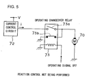
- a drive circuit for the servo motor 70 is shown in FIGS. 5 and 6.
- An electric current control circuit 72 is connected to the servo motor 70 via an operation changeover relay 73.
- This current control circuit 72 outputs an electrical current i according to the command value of the accelerator pedal reaction force control device 60.
- An ON signal is outputted from the accelerator pedal reaction force control device 60 to the coil of the operation changeover relay 73 when the system is operating, while an OFF signal is outputted thereto when the system is not operating.
- the relay contact points 73a and 73b are opened and closed by this ON/OFF signal, so that the characteristic of the reaction force F with respect to the stroke S of the accelerator pedal 80 is changed over between a first characteristic and a second characteristic which will be explained hereinafter. It should be understood that this operation changeover relay 73 constitutes a selection means.
- the controller 50 recognizes the running situation or state such as the distance between vehicles (the distance to the vehicle in front of the subject vehicle), their relative speed, and the running vehicle speed of the subject vehicle, and, based upon this running situation, calculates the present degree of proximity to the vehicle in front (a first risk level), and the degree of influence upon the subject vehicle due to the trend of the future movement of the vehicle in front as predicted from the present (a second risk level) . Furthermore, the controller 50 predicts the future running situation or state (a risk potential RP) from the degree of proximity and the predicted degree of influence which have thus been calculated, calculates an accelerator pedal reaction force command value ⁇ F based upon this risk potential RP, and outputs this command value ⁇ F to the accelerator pedal reaction force control device 60.
- the accelerator pedal reaction force control device 60 controls the servo motor 70 according to this command value ⁇ F, and thereby the stroke reaction force characteristic of the accelerator pedal 80 is changed.
- the reaction force characteristic in the normal state in other words when the accelerator pedal reaction force control is not being performed by the reaction force control device 1 (i.e. when the system is not operating), is endowed with a hysteresis when the accelerator pedal 80 is stepped upon and is released, as shown by the dotted portion in the figure. Due to this, it is possible to keep the pedal stroke S constant even if the force by which the pedal is stepped upon varies by a certain amount, so that the maintainability of the pedal stroke S is enhanced.
- reaction force control i.e. when the system is operating
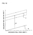
- an accelerator pedal reaction force F is generated which is increased over the reaction force characteristic during the normal state by just the accelerator pedal reaction force command value ⁇ F. Due to this, the reaction force F of the accelerator pedal 80 comes to be determined according to the risk potential RP, and it is possible to cause the present and the future predicted running situation of the vehicle to be recognised by the driver of the vehicle via this accelerator pedal reaction force F. In this case, in order for the risk to be accurately sensed by the driver, it is desirable for the system to be endowed with a straight line characteristic with no hysteresis, as shown in FIG. 12.
- FIG. 7 is a flow chart showing the processing flow of an accelerator pedal reaction force control program which is performed by the controller 50. The steps of this procedure are performed repeatedly in sequence at a fixed time interval (for example 50 msec).
- the vehicle running state comprising the speed Vf of the subject vehicle, the distance D between vehicles to the vehicle in front, the relative speed Vr, and the speed of the vehicle in front Va, as detected by the laser radar 10 and the vehicle speed sensor 20, are read in.
- the present degree of proximity to the vehicle in front and the predicted degree of influence upon the subject vehicle due to change in the surrounding environment from now on are calculated.
- a time to contact between vehicles TTC is calculated as the degree of proximity to the vehicle in front
- a time headway between vehicles THW is calculated as the predicted degree of influence.
- the time to contact between vehicles TTC may be referred to as a clearance time period between vehicles and the time headway between vehicles THW may be referred to as a time period between vehicles.
- the time to contact between vehicles TTC is a physical quantity that gives the current degree of proximity of the subject vehicle with respect to the vehicle in front.
- the subject vehicle is running so as just to track after the vehicle in front without catching it up, then its relative vehicle speed Vr with respect to the vehicle in front is 0, and the time to contact between vehicles TTC is infinitely large.
- the risk which the driver feels is different if the distance between vehicles D is long or if it is short, and in fact the driver feels that the risk is the greater, the shorter is the distance between vehicles D.
- the driver predicts the amount of influence upon the time to contact between vehicles TTC which will be caused by the variation in the future of the vehicle speed of the vehicle in front which he hypothesizes, and feels the risk to be the greater, if he recognizes that this influence is large.
- This time headway between vehicles THW is the distance between vehicles D divided by the running speed of the vehicle in front Va or by the speed Vf of the subject vehicle Vf, and it represents the time period until the subject vehicle arrives at the current position of the vehicle in front.
- Equation (2) which uses the running speed Va of the vehicle in front is in better accordance with the risk which is experienced by the driver, than Equation (3) which uses the running speed of the subject vehicle Vf.
- the running speed Va of the vehicle in front is calculated from the speed of the subject vehicle Vf and the relative vehicle speed Vr, accordingly it is possible to calculate the time headway between vehicles THW more accurately from Equation (2) which uses the subject vehicle speed Vf, which is detected with high accuracy by the vehicle speed sensor 20.
- Equation (2) is the same as Equation (3), since the subject vehicle speed Vf is equal to the running speed Va of the vehicle in front.
- the time to contact between vehicles TTC and the time headway between vehicles THW are calculated.
- the predicted future situation (the risk potential RP) is calculated based upon the time to contact between vehicles TTC and the time headway between vehicles THW which have thus been calculated in the step S120.
- This risk potential RP is given by the following Equation (4), and is a physical quantity which is given continuously as the sum of the degree of proximity to the vehicle in front (1/TTC) and the predicted degree of influence upon the future situation (1/THW), as adjusted by certain coefficients.
- RP a / THW + b / TTC
- the time to contact between vehicles TTC is the risk level regarding how many seconds the subject vehicle will take to come into contact with the vehicle in front , when it is assumed that the relative speed Vr between the vehicle in front and the subject vehicle is constant, while the time headway between vehicles THW is the risk level regarding how many seconds the subject vehicle will take to arrive at the current position where the vehicle in front is located , when it is assumed that the relative speed Vr between the vehicle in front and the subject vehicle will change in the future.
- This time to contact between vehicles TTC and time headway between vehicles THW are individually calculated from the present subject vehicle speed Vf, the speed Va of the vehicle in front, and the relative vehicle speed Vr, but it is possible to estimate the risk potential RP which is predicted for the future by adjusting these using Equation (4).
- the risk potential RP is possible to correspond to the continuous change of the situation from tracking after the vehicle in front until approaching to the vehicle in front, and it is possible to express the degree of proximity in these circumstances. In other words, it is possible to determine that, the greater is the risk potential, the greater does the driver feel the risk of perhaps coming too close to the vehicle in front in the future to be.
- the risk potential RP which is calculated from Equation (4) is shown, in a planar chart of the time headway between vehicles THW against the reciprocal of the time to contact between vehicles (1/TTC), as each line has each value of the risk potential RP.
- the time headway between vehicles THW is shown along the horizontal axis
- the reciprocal (1/TTC) of the time to contact between vehicles TTC is shown along the vertical axis; and, the more to the right along the horizontal axis, the farther is the subject vehicle running from the vehicle in front, while, the more upwards along the vertical axis, the closer is the subject vehicle to the vehicle in front, while the lower therealong, the farther is it removed from the vehicle in front.
- each line of equal risk potential RP is drawn as a smooth line from the upper right to the lower left, and the value of the risk potential RP changes continuously between these lines of equal risk potential.
- the degree of proximity 1/TTC has the same value, the shorter is the time headway between vehicles THW, the greater does the value of the risk potential RP become.
- step S131 a decision is made as to whether or not the risk potential RP which has been calculated in the step S130 is greater than a predetermined value. If it is decided that the risk potential RP is greater than the predetermined value, then the flow of control is transferred to the step S132. In the step 132, a signal to turn on the operation changeover relay 73 is output (the state of FIG. 6), and the flow of control is transferred to the step S140. In the step 131, if it is decided that the risk potential RP is not greater than the predetermined value, then the flow of control is transferred to the step S133. In the step 133, a signal to turn off the operation changeover relay 73 is output (the state of FIG. 5), and the control is terminated. In the step S131 through the step S133, it is decide or selected based upon the risk potential RP according to the running situation of the vehicle whether or not the control explained below to apply a reaction force corresponding to the reaction force command value ⁇ F is performed.
- K is a constant value which should be set appropriately.
- the risk potential RP is given continuously for every running situation as defined by the time headway between vehicles THW and degree of proximity 1/TTC.
- step S150 the accelerator pedal reaction force command value ⁇ F which was calculated in the step S140 is outputted to the accelerator pedal reaction force control device 60, and then this episode of processing terminates.
- the value of the risk potential RP was calculated by weighting the present degree of proximity (1/TTC) and the predicted degree of influence (1/THW) individually and adding together with them using Equation (4) .
- RP max ⁇ a / THW , b / TTC ⁇
- Equation (6) the value of the maximum one among the degree of proximity (the reciprocal of TTC) to the vehicle in front and the predicted degree of influence (the reciprocal of THW) in the future state is selected as the value of the risk potential RP.
- the risk potential RP which is calculated from Equation (6) is shown, in a planar chart of the time headway between vehicles THW against the reciprocal of the time to contact between vehicles (1/TTC), as each line has each value of the risk potential RP.
- the time headway between vehicles THW is shown along the horizontal axis
- the reciprocal (1/TTC) of the time to contact between vehicles TTC is shown along the vertical axis.
- the greater one of the present degree of proximity to the vehicle in front (1/TTC) and the predicted degree of influence (1/THW) in the future is selected. Due to this, even if the degree of proximity (1/TTC) is negative, in other words even if the relative vehicle speed is negative, the value of the risk potential RP does not drop below a predetermined value which is determined by the time headway between vehicles THW, as shown in FIG. 10. It should be understood that the time headway between vehicles THW is the time period for the subject vehicle to arrive at the current position of the vehicle in front, so that it can never have a negative value. Due to this, when the risk potential RP is calculated by using the above Equation (6), it is possible to prevent sudden change of the value of the risk potential RP, which would cause an undesirable sudden change of the accelerator pedal reaction force.
- the present degree of proximity to the vehicle in front (the time to contact between vehicles TTC) and the degree of influence due to change of the surrounding environment of the vehicle which is predicted for the future (the time headway between vehicles THW) are calculated, and these are added together with individual weightings in order to calculate the risk potential RP.
- the accelerator pedal reaction force by additionally applying a force which is proportional to this risk potential RP to the accelerator pedal reaction force, it becomes possible to control the reaction force of the accelerator pedal based upon a value which is close to the risk level which is actually felt by the driver of the vehicle. If the present degree of proximity to the vehicle in front is great (i.e.
- the accelerator pedal reaction force command value ⁇ F is determined based upon the risk potential RP which has been calculated using Equation (4), the risk potential RP changes continuously as shown in FIG. 9. Due to this, it is possible to cause the driver to recognize the vehicle running situation which corresponds to the degree of proximity 1/TTC to the vehicle in front and to the time headway between vehicles THW, via the accelerator pedal reaction force which is continuously transmitted to him. Furthermore, if the risk potential RP is calculated using Equation (6), the risk potential changes as shown in FIG. 10. Due to this, even if the vehicle in front accelerates away from the subject vehicle so that the degree of proximity 1/TTC becomes extremely small, it is still possible to perform accelerator pedal reaction force control in a stabilized manner, since the risk potential RP never changes abruptly.
- the time to contact between vehicles TTC and the time headway between vehicles THW can be calculated using physical quantities which are each comparatively easy to calculate, such as the subject vehicle speed Vf, the speed of the vehicle in front Va, the distance between vehicles D, and the like, accordingly it is possible to suppress increase in the number of component parts which are required for the construction of this driving actuation assistance device for a vehicle.
- the laser radar 10 of the subject vehicle detects the vehicle in front, and the reaction force control system starts to operate when the risk potential exceeds a predetermined value. Due to the operation of this system, the coil of the operation changeover relay 73 is supplied with electrical current as shown in FIG. 6, and the contact points 73a of this relay 73 are closed, while its contact points 73b are opened.
- the controller 50 calculates the risk potential RP with respect to the vehicle in front as has been previously described, and the accelerator pedal reaction force control device 60 controls the output of the electric current control circuit 72 according to this calculated risk potential RP. Due to this, the torque of the servo motor 70 is controlled, and a motor torque reaction force ⁇ F which corresponds to the risk potential RP is additionally applied to the accelerator pedal 80 by being added to the reaction force which is produced by the tension spring 85.
- reaction force F which is applied to the accelerator pedal 80 is shown by the characteristic f1 of FIG. 12.
- this characteristic f1 is a first characteristic
- the characteristic f0 in the figure is the reaction force characteristic of the tension spring 85 which serves as the base for this first characteristic f1. Since there is no sliding portion in the tension spring 85 such as is present in a torsion spring, the frictional force is smaller than if a torsion spring were to be employed. As a result, the generation of hysteresis is suppressed, and the spring reaction force which serves as a base changes in a linear manner, as shown by the characteristic f0.
- reaction force characteristic By providing a reaction force characteristic in this manner in which the frictional force of the spring and the mechanical loss of the gears is small so that there is no substantial hysteresis, the driver is enabled easily to sense the risk of approach to the vehicle in front.
- the reaction force characteristic were to have hysteresis as shown by the dotted line in FIG. 12, even if a reaction force ⁇ F corresponding to the risk potential were to be applied to the accelerator pedal 80, it would be difficult for the driver accurately to apprehend the degree of risk, since there would be a danger that he might misunderstand the increase of the reaction force due to the influence of such hysteresis.
- the reaction force characteristic is linear, the driver can recognize the increase of reaction force as the increase of the risk directly, and he is able accurately to sense the risk of perhaps getting too close to the vehicle in front in the future.
- the reaction control system does not operate.
- this system is not operating, as shown in FIG. 5, the supply of electric current to the coil of the operation changeover relay 73 is interrupted, and the contact points 73a of this relay 73 are opened, while its contact points 73b are closed. Due to this, both of the terminals of the servo motor 70 are grounded. In other words, both of the terminals are shorted. If at this time the accelerator pedal 80 is stepped down upon or is released, the output shaft 70a of the servo motor 70 is rotated according to this pedal actuation, and an induced electromotive force is generated in this servo motor 70.
- This induced electromotive force acts as a viscous force so as to impede the actuation of the accelerator pedal 80.
- the pedal reaction force F exhibits a second characteristic which is endowed with hysteresis.
- the aforementioned viscous force is added to the spring reaction force (the characteristic f2), and the pedal reaction force F is increased as shown by the arrow sign.
- the characteristic f2 the spring reaction force
- the accelerator pedal device according to the present invention is not to be considered as being limited to the above described preferred embodiment; various modifications are possible.
- a reaction force characteristic having hysteresis when the system was not operating was provided by self-induction of the servo motor 70
- reaction force was applied to the accelerator pedal 80 by the use of the servo motor 70
- some other type of actuator provided that it was one which could adjust the applied reaction force as desired.
- some type of control other than one according to the risk potential to the accelerator pedal device of the present invention it would also be possible to apply some type of control other than one according to the risk potential to the accelerator pedal device of the present invention to some other type of control, provided that it was one in which reaction force control was to be performed according to the vehicle operational state or the running environment in the surroundings of the vehicle.
- reaction force control it is desirable to apply reaction force in a no hysteresis state, it is not absolutely necessary for no hysteresis at all to be applied during such reaction force control.
- tension spring 85 it would also be possible to employ a spring member which had some other structure.
- the step S131 through the step S133 in FIG. 7 it is selected by executing the step S131 through the step S133 in FIG. 7 whether or not the reaction force corresponding to the reaction force command value ⁇ F is applied.
- the step S131 through the step S133 may be deleted.
- the electric current control circuit 72 is always connected to the servo motor 70.
- the characteristic in which the reaction force corresponding to the reaction force command value ⁇ F is not applied is substantially selected.
Applications Claiming Priority (2)
| Application Number | Priority Date | Filing Date | Title |
|---|---|---|---|
| JP2002180005A JP3700682B2 (ja) | 2002-06-20 | 2002-06-20 | アクセルペダル装置 |
| EP03012897A EP1375232B1 (de) | 2002-06-20 | 2003-06-06 | Gaspedalanordnung und Verfahren zum Einstellen von dessen Reaktionskraft |
Related Parent Applications (1)
| Application Number | Title | Priority Date | Filing Date |
|---|---|---|---|
| EP03012897A Division EP1375232B1 (de) | 2002-06-20 | 2003-06-06 | Gaspedalanordnung und Verfahren zum Einstellen von dessen Reaktionskraft |
Publications (2)
| Publication Number | Publication Date |
|---|---|
| EP1634759A1 true EP1634759A1 (de) | 2006-03-15 |
| EP1634759B1 EP1634759B1 (de) | 2007-10-10 |
Family
ID=29717510
Family Applications (2)
| Application Number | Title | Priority Date | Filing Date |
|---|---|---|---|
| EP05026509A Expired - Fee Related EP1634759B1 (de) | 2002-06-20 | 2003-06-06 | Gaspedalanordnung |
| EP03012897A Expired - Fee Related EP1375232B1 (de) | 2002-06-20 | 2003-06-06 | Gaspedalanordnung und Verfahren zum Einstellen von dessen Reaktionskraft |
Family Applications After (1)
| Application Number | Title | Priority Date | Filing Date |
|---|---|---|---|
| EP03012897A Expired - Fee Related EP1375232B1 (de) | 2002-06-20 | 2003-06-06 | Gaspedalanordnung und Verfahren zum Einstellen von dessen Reaktionskraft |
Country Status (4)
| Country | Link |
|---|---|
| US (2) | US6920385B2 (de) |
| EP (2) | EP1634759B1 (de) |
| JP (1) | JP3700682B2 (de) |
| DE (2) | DE60316850T2 (de) |
Cited By (1)
| Publication number | Priority date | Publication date | Assignee | Title |
|---|---|---|---|---|
| FR2913119A1 (fr) * | 2007-02-23 | 2008-08-29 | Peugeot Citroen Automobiles Sa | Systeme de pedale de commande de vehicule, notamment de vehicule automobile |
Families Citing this family (58)
| Publication number | Priority date | Publication date | Assignee | Title |
|---|---|---|---|---|
| JP3573134B2 (ja) * | 2002-02-25 | 2004-10-06 | 日産自動車株式会社 | 車両用運転操作補助装置 |
| JP4203363B2 (ja) * | 2003-06-10 | 2008-12-24 | 本田技研工業株式会社 | 車両用の操作装置 |
| JP2005090347A (ja) * | 2003-09-17 | 2005-04-07 | Honda Motor Co Ltd | 車両用アクセルペダル装置 |
| JP4254501B2 (ja) * | 2003-11-20 | 2009-04-15 | 日産自動車株式会社 | 車両用運転操作補助装置および車両用運転操作補助装置を備えた車両 |
| JP4419531B2 (ja) * | 2003-11-20 | 2010-02-24 | 日産自動車株式会社 | 車両用運転操作補助装置および車両用運転操作補助装置を備える車両 |
| US7349767B2 (en) * | 2003-12-16 | 2008-03-25 | Nissan Motor Co., Ltd. | Method and system for intention estimation and operation assistance |
| JP4281543B2 (ja) * | 2003-12-16 | 2009-06-17 | 日産自動車株式会社 | 車両用運転操作補助装置および車両用運転操作補助装置を備えた車両 |
| JP4561092B2 (ja) * | 2003-12-16 | 2010-10-13 | 日産自動車株式会社 | 車両用運転操作補助装置および車両用運転操作補助装置を備えた車両 |
| JP4226455B2 (ja) | 2003-12-16 | 2009-02-18 | 日産自動車株式会社 | 運転意図推定装置、車両用運転操作補助装置および車両用運転操作補助装置を備えた車両 |
| JP4020089B2 (ja) * | 2004-03-03 | 2007-12-12 | 日産自動車株式会社 | 車両用運転操作補助装置および車両用運転操作補助装置を備えた車両 |
| JP3960317B2 (ja) * | 2004-03-03 | 2007-08-15 | 日産自動車株式会社 | 車両用運転操作補助装置および車両用運転操作補助装置を備えた車両 |
| JP3960316B2 (ja) * | 2004-03-03 | 2007-08-15 | 日産自動車株式会社 | 車両用運転操作補助装置および車両用運転操作補助装置を備えた車両 |
| JP3956948B2 (ja) | 2004-03-11 | 2007-08-08 | 日産自動車株式会社 | 車両用運転操作補助装置および車両用運転操作補助装置を備える車両 |
| JP4313243B2 (ja) | 2004-04-26 | 2009-08-12 | 豊田鉄工株式会社 | 車両用電気式操作装置 |
| JP4367254B2 (ja) * | 2004-06-16 | 2009-11-18 | 日産自動車株式会社 | 車両用運転操作補助装置および車両用運転操作補助装置を備えた車両 |
| JP4367319B2 (ja) | 2004-11-12 | 2009-11-18 | 日産自動車株式会社 | 車両用運転操作補助装置および車両用運転操作補助装置を備えた車両 |
| JP2007022238A (ja) * | 2005-07-14 | 2007-02-01 | Nissan Motor Co Ltd | 車両用運転操作補助装置および車両用運転操作補助装置を備えた車両 |
| JP4581878B2 (ja) * | 2005-07-19 | 2010-11-17 | トヨタ自動車株式会社 | ペダル反力制御装置 |
| JP4413835B2 (ja) * | 2005-08-24 | 2010-02-10 | 日産自動車株式会社 | 車両用運転操作補助装置および車両用運転操作補助装置を備えた車両 |
| JP4752679B2 (ja) | 2005-10-13 | 2011-08-17 | 日産自動車株式会社 | 車両用運転操作補助装置 |
| JP2007145119A (ja) * | 2005-11-25 | 2007-06-14 | Toyota Motor Corp | 車両の制御装置 |
| JP4788611B2 (ja) | 2006-03-10 | 2011-10-05 | 日産自動車株式会社 | 車間維持支援装置および車間維持支援方法 |
| JP4788464B2 (ja) * | 2006-04-28 | 2011-10-05 | 日産自動車株式会社 | 車間維持支援装置および車間維持支援方法 |
| US20090326780A1 (en) * | 2006-08-16 | 2009-12-31 | Adc Automotive Distance Control Systems Gmbh | Method for distance control |
| DE102006046216B3 (de) * | 2006-09-29 | 2008-05-29 | Siemens Ag | Verfahren und Vorrichtung zum Betreiben eines Kraftfahrzeugs |
| KR100844559B1 (ko) * | 2006-12-14 | 2008-07-08 | 현대자동차주식회사 | 가속 페달 시스템 |
| US7783461B2 (en) * | 2007-05-04 | 2010-08-24 | Toyota Motor Engineering & Manufacturing North America, Inc. | Systems and methods for simulating vehicle operation |
| JP5278162B2 (ja) * | 2008-07-31 | 2013-09-04 | 日産自動車株式会社 | アクセルペダル踏力制御装置 |
| DE102009021587A1 (de) * | 2009-05-15 | 2010-11-25 | Conti Temic Microelectronic Gmbh | Verfahren und Vorrichtung zur Geschwindigkeitsregelung |
| JP5471483B2 (ja) * | 2010-01-18 | 2014-04-16 | トヨタ自動車株式会社 | 車両走行制御装置 |
| DE102010010400A1 (de) * | 2010-03-05 | 2011-09-08 | GM Global Technology Operations LLC , (n. d. Ges. d. Staates Delaware) | Fahrpedal für ein Kraftfahrzeug und Verfahren zum Betrieb des Fahrpedals |
| JP5406109B2 (ja) * | 2010-04-14 | 2014-02-05 | 功 松野 | 回生協調ブレーキ用ストロークシミュレータ |
| EP2613217B1 (de) * | 2010-08-31 | 2017-10-11 | Honda Motor Co., Ltd. | Reaktionskraft-pedalvorrichtung |
| KR101156142B1 (ko) | 2010-09-10 | 2012-06-18 | 에스엘 주식회사 | 능동형 페달 장치 |
| EP2620313B1 (de) * | 2010-09-21 | 2017-09-06 | Honda Motor Co., Ltd. | Beschleunigkeitspedalvorrichtung für ein fahrzeug und verfahren zur steuerung von dessen pedalreaktionskraft |
| JP5675016B2 (ja) * | 2010-12-01 | 2015-02-25 | 株式会社ミクニ | アクセルペダル装置 |
| KR101338708B1 (ko) * | 2010-12-06 | 2013-12-16 | 현대자동차주식회사 | 차량의 가속페달 제어방법 |
| JP5740175B2 (ja) * | 2011-02-21 | 2015-06-24 | 株式会社ミクニ | アクセルペダル装置 |
| JP5806480B2 (ja) * | 2011-02-23 | 2015-11-10 | 株式会社ミクニ | アクセルペダル装置 |
| JP5809459B2 (ja) | 2011-06-27 | 2015-11-11 | 株式会社ミクニ | アクセルペダル装置 |
| DE102011054655A1 (de) * | 2011-10-20 | 2013-04-25 | Ab Elektronik Gmbh | Pedaleinheit für ein KFZ |
| US9056617B2 (en) * | 2011-12-02 | 2015-06-16 | Ford Global Technologies, Llc | Systems and methods for detecting accelerator pedal failure |
| KR101470145B1 (ko) * | 2013-04-23 | 2014-12-05 | 현대자동차주식회사 | 가속페달 장치의 답력 능동 조절방법 |
| KR101406592B1 (ko) * | 2013-05-07 | 2014-06-11 | 기아자동차주식회사 | 가속페달 장치의 답력 능동 조절방법 |
| US10124673B2 (en) | 2013-10-08 | 2018-11-13 | Honda Lock Mfg. Co., Ltd. | Reaction force output device |
| JP6140590B2 (ja) * | 2013-10-08 | 2017-05-31 | 株式会社ホンダロック | 反力出力装置 |
| JP6131174B2 (ja) * | 2013-11-13 | 2017-05-17 | 株式会社ホンダロック | 反力出力装置 |
| JP6198768B2 (ja) * | 2015-04-27 | 2017-09-20 | 本田技研工業株式会社 | ペダル反力付与装置 |
| DE102015214490A1 (de) * | 2015-07-30 | 2017-02-02 | Continental Automotive Gmbh | Fahrpedalvorrichtung mit einem Pedalelement sowie einer Gegenkraftvorrichtung |
| CN107010065A (zh) * | 2016-09-23 | 2017-08-04 | 阿里巴巴集团控股有限公司 | 汽车辅助方法、装置及系统 |
| DE102017004536A1 (de) * | 2017-05-11 | 2018-11-15 | Lucas Automotive Gmbh | System und Verfahren zur vorausschauenden Geschwindigkeitsbeeinflussung eines Kraftfahrzeugs |
| US10960924B2 (en) | 2017-06-16 | 2021-03-30 | Toyota Research Institute, Inc. | Vehicle systems for adjusting resistance or sensitivity of steering wheels and/or accelerator pedals |
| JP6528806B2 (ja) * | 2017-06-22 | 2019-06-12 | マツダ株式会社 | 車両用制御装置 |
| JP6521491B1 (ja) * | 2017-12-01 | 2019-05-29 | マツダ株式会社 | 車両の制御装置 |
| KR102388154B1 (ko) * | 2017-12-07 | 2022-04-19 | 현대자동차주식회사 | 자동차 및 그를 위한 속도 제한 제어 방법 |
| WO2020157949A1 (ja) * | 2019-02-01 | 2020-08-06 | 株式会社ミクニ | アクセルペダル装置 |
| JP7225923B2 (ja) * | 2019-03-04 | 2023-02-21 | 富士通株式会社 | 強化学習方法、強化学習プログラム、および強化学習システム |
| JP2023062539A (ja) * | 2021-10-21 | 2023-05-08 | 株式会社デンソー | 反力付与装置 |
Citations (7)
| Publication number | Priority date | Publication date | Assignee | Title |
|---|---|---|---|---|
| JPH05231194A (ja) * | 1992-02-26 | 1993-09-07 | Nippondenso Co Ltd | アクセルペダルの踏込反力制御装置 |
| DE19506629A1 (de) * | 1995-02-25 | 1996-08-29 | Pierburg Gmbh | Fahrpedalanordnung für Fahrzeug-Brennkraftmaschinen |
| WO1997030863A1 (en) * | 1996-02-26 | 1997-08-28 | Adwest Rearsby Limited | Damped pedal mounting |
| EP0899147A1 (de) * | 1997-08-27 | 1999-03-03 | Mannesmann VDO Aktiengesellschaft | Fahrpedal mit Dämpfungseinrichtung |
| DE19916434A1 (de) * | 1999-04-12 | 2000-10-19 | Deutsch Zentr Luft & Raumfahrt | Elektromechanisch angetriebenes schwenkbares Pedal |
| DE10042549A1 (de) * | 2000-08-30 | 2002-03-14 | Volkswagen Ag | Fahrpedalmodul |
| DE10122162A1 (de) * | 2001-05-08 | 2002-11-14 | Volkswagen Ag | Verfahren zur Steuerung eines automatisierten Stufenwechselgetriebes und Fahrpedalvorrichtung |
Family Cites Families (34)
| Publication number | Priority date | Publication date | Assignee | Title |
|---|---|---|---|---|
| JPS5913178Y2 (ja) | 1980-01-25 | 1984-04-19 | 日産車体株式会社 | 自動車用吊下げ式ペダル |
| JPS5733048A (en) * | 1980-08-04 | 1982-02-23 | Honda Motor Co Ltd | Throttle reaction control device of car |
| JPS57167845A (en) | 1981-04-07 | 1982-10-15 | Honda Motor Co Ltd | Vehicle throttle reaction force control system |
| JPH035937Y2 (de) | 1985-09-20 | 1991-02-15 | ||
| JPS63258225A (ja) | 1987-04-16 | 1988-10-25 | Showa Denko Kk | 合成樹脂製アクセルペダル |
| JP2871717B2 (ja) | 1989-05-01 | 1999-03-17 | マツダ株式会社 | 移動車の走行制御装置 |
| JP2658467B2 (ja) | 1990-01-22 | 1997-09-30 | 日産自動車株式会社 | アクセル反力制御装置 |
| JPH0550871A (ja) * | 1991-08-21 | 1993-03-02 | Hitachi Ltd | 電動スロツトルアクチユエータ |
| JP3197307B2 (ja) * | 1991-10-14 | 2001-08-13 | マツダ株式会社 | 移動車の走行制御装置 |
| JPH05345536A (ja) | 1992-06-15 | 1993-12-27 | Toyota Autom Loom Works Ltd | 産業車両のアクセル装置 |
| JPH074211U (ja) | 1993-06-16 | 1995-01-20 | 日産ディーゼル工業株式会社 | 車両の追突防止装置 |
| JPH0817000A (ja) | 1994-06-28 | 1996-01-19 | Toyota Motor Corp | 車間距離制御装置 |
| JPH0826310A (ja) | 1994-07-11 | 1996-01-30 | Dainippon Printing Co Ltd | ラミネートチューブ容器 |
| JPH08166448A (ja) | 1994-12-13 | 1996-06-25 | Honda Motor Co Ltd | 車両用周囲監視装置 |
| JP3634436B2 (ja) | 1995-03-27 | 2005-03-30 | 三菱プレシジョン株式会社 | 模擬運転装置用クラッチペダル反力発生装置、模擬運転装置用ブレーキペダル反力発生装置及び模擬運転装置用ペダル反力発生装置 |
| DE19536699A1 (de) * | 1995-09-30 | 1997-04-03 | Bosch Gmbh Robert | Fahrpedalmodul |
| JPH09254677A (ja) | 1996-03-21 | 1997-09-30 | Hiruta Kogyo Kk | アクセルペダル |
| DE19620929A1 (de) * | 1996-05-24 | 1997-11-27 | Porsche Ag | Längsregelsystem für Kraftfahrzeuge mit haptischem Gaspedal |
| JPH10166890A (ja) | 1996-12-04 | 1998-06-23 | Suzuki Motor Corp | 警報装置 |
| JPH10166889A (ja) | 1996-12-04 | 1998-06-23 | Suzuki Motor Corp | 警報装置 |
| JPH10318009A (ja) | 1997-05-16 | 1998-12-02 | Mitsubishi Electric Corp | 車両用追従走行制御装置 |
| JP3209406B2 (ja) | 1997-06-06 | 2001-09-17 | 本田技研工業株式会社 | 車両用運転支援装置 |
| JP3906525B2 (ja) | 1997-09-01 | 2007-04-18 | 日産自動車株式会社 | 車速設定装置 |
| DE19820929A1 (de) | 1998-05-09 | 1999-11-11 | Ako Werke Gmbh & Co | Vorrichtung zum Steuern eines Einphasen-Synchronmotors |
| JP2000054860A (ja) | 1998-08-10 | 2000-02-22 | Denso Corp | 自動走行制御装置及びペダル反力調整器並びに記録媒体 |
| JP2000158970A (ja) | 1998-11-30 | 2000-06-13 | Toyota Autom Loom Works Ltd | アクセルペダル反力制御装置 |
| JP2000296724A (ja) | 1999-04-14 | 2000-10-24 | Fujitsu Ten Ltd | 車間制御装置 |
| JP3738613B2 (ja) | 1999-08-10 | 2006-01-25 | 日産自動車株式会社 | 車線追従装置 |
| JP2001171497A (ja) | 1999-12-17 | 2001-06-26 | Nissan Motor Co Ltd | 車両用衝突防止装置 |
| JP3983495B2 (ja) * | 2001-04-25 | 2007-09-26 | 株式会社日立製作所 | 車両のペダル装置及びそれを備えた車両 |
| JP3785959B2 (ja) * | 2001-07-19 | 2006-06-14 | 日産自動車株式会社 | 車両用走行制御装置 |
| EP1285842B1 (de) * | 2001-08-23 | 2008-05-28 | Nissan Motor Co., Ltd. | Fahrassistenzsystem |
| US7770491B2 (en) | 2001-11-05 | 2010-08-10 | Continental Teves Ag & Co. Ohg | Device with additional restoring force on the gas pedal based on the deviation of a vehicle parameter from the set value |
| JP3651793B2 (ja) * | 2002-04-03 | 2005-05-25 | 本田技研工業株式会社 | 車両用アクセルペダル装置 |
-
2002
- 2002-06-20 JP JP2002180005A patent/JP3700682B2/ja not_active Expired - Fee Related
-
2003
- 2003-06-06 EP EP05026509A patent/EP1634759B1/de not_active Expired - Fee Related
- 2003-06-06 EP EP03012897A patent/EP1375232B1/de not_active Expired - Fee Related
- 2003-06-06 DE DE60316850T patent/DE60316850T2/de not_active Expired - Lifetime
- 2003-06-06 DE DE60304628T patent/DE60304628T2/de not_active Expired - Lifetime
- 2003-06-17 US US10/462,736 patent/US6920385B2/en not_active Expired - Lifetime
-
2005
- 2005-05-17 US US11/130,085 patent/US7076358B2/en not_active Expired - Lifetime
Patent Citations (7)
| Publication number | Priority date | Publication date | Assignee | Title |
|---|---|---|---|---|
| JPH05231194A (ja) * | 1992-02-26 | 1993-09-07 | Nippondenso Co Ltd | アクセルペダルの踏込反力制御装置 |
| DE19506629A1 (de) * | 1995-02-25 | 1996-08-29 | Pierburg Gmbh | Fahrpedalanordnung für Fahrzeug-Brennkraftmaschinen |
| WO1997030863A1 (en) * | 1996-02-26 | 1997-08-28 | Adwest Rearsby Limited | Damped pedal mounting |
| EP0899147A1 (de) * | 1997-08-27 | 1999-03-03 | Mannesmann VDO Aktiengesellschaft | Fahrpedal mit Dämpfungseinrichtung |
| DE19916434A1 (de) * | 1999-04-12 | 2000-10-19 | Deutsch Zentr Luft & Raumfahrt | Elektromechanisch angetriebenes schwenkbares Pedal |
| DE10042549A1 (de) * | 2000-08-30 | 2002-03-14 | Volkswagen Ag | Fahrpedalmodul |
| DE10122162A1 (de) * | 2001-05-08 | 2002-11-14 | Volkswagen Ag | Verfahren zur Steuerung eines automatisierten Stufenwechselgetriebes und Fahrpedalvorrichtung |
Non-Patent Citations (1)
| Title |
|---|
| PATENT ABSTRACTS OF JAPAN vol. 017, no. 686 (M - 1529) 15 December 1993 (1993-12-15) * |
Cited By (1)
| Publication number | Priority date | Publication date | Assignee | Title |
|---|---|---|---|---|
| FR2913119A1 (fr) * | 2007-02-23 | 2008-08-29 | Peugeot Citroen Automobiles Sa | Systeme de pedale de commande de vehicule, notamment de vehicule automobile |
Also Published As
| Publication number | Publication date |
|---|---|
| DE60304628D1 (de) | 2006-05-24 |
| EP1375232B1 (de) | 2006-04-19 |
| US20030236608A1 (en) | 2003-12-25 |
| EP1634759B1 (de) | 2007-10-10 |
| JP2004017935A (ja) | 2004-01-22 |
| US20050209743A1 (en) | 2005-09-22 |
| DE60304628T2 (de) | 2007-04-05 |
| EP1375232A1 (de) | 2004-01-02 |
| US7076358B2 (en) | 2006-07-11 |
| JP3700682B2 (ja) | 2005-09-28 |
| DE60316850D1 (de) | 2007-11-22 |
| DE60316850T2 (de) | 2008-10-02 |
| US6920385B2 (en) | 2005-07-19 |
Similar Documents
| Publication | Publication Date | Title |
|---|---|---|
| EP1634759B1 (de) | Gaspedalanordnung | |
| US7308839B2 (en) | Accelerator pedal device | |
| US7200481B2 (en) | Driving assist system for vehicle | |
| KR100723277B1 (ko) | 차량의 주행 속도 제어 방법 및 제어 장치 | |
| US9108510B2 (en) | Method and control device for controlling foreseeable haptically perceivable signals in an acceleration pedal of a motor vehicle | |
| US6982647B2 (en) | Driving assist system for vehicle | |
| EP1829739B1 (de) | Kopfstützensteuersystem | |
| US20030233187A1 (en) | Driving assist system for vehicle | |
| JP2018144678A (ja) | 車両制御装置 | |
| JP2007512598A (ja) | 自動車の運転者に警告する方法および装置 | |
| WO2005084992A1 (en) | Method and system for assisting a driver of a vehicle operating a vehicle traveling on a road | |
| EP2000380A9 (de) | Vorrichtung und verfahren zur fahrtsteuerung eines fahrzeuges | |
| KR20200089275A (ko) | 적어도 부분적으로 자동으로 주행하는 자동차를 위한 운전자 보조 시스템, 자동차 및 자동차 동역학을 제어하기 위한 방법 | |
| KR20080027834A (ko) | 적응성 속도 조절기를 포함하는 자동차용 방향 지시 스위치 | |
| CN102264572A (zh) | 车辆座椅控制装置及其控制方法 | |
| JP3956948B2 (ja) | 車両用運転操作補助装置および車両用運転操作補助装置を備える車両 | |
| CN109017725A (zh) | 用于调节自动制动系统超驰阈值的方法 | |
| JP4179304B2 (ja) | アクセルペダル装置 | |
| KR102060303B1 (ko) | 자율 주행 제어 장치 및 방법 | |
| US20210094570A1 (en) | Human-machine interface apparatus for vehicle | |
| JP3966310B2 (ja) | アクセルペダル装置 | |
| CN109311483B (zh) | 用于辅助驾驶员的方法 | |
| JP4079128B2 (ja) | アクセルペダル装置 | |
| CN117337257A (zh) | 用于确定车辆的加速度预设的方法和装置 | |
| CN116279419A (zh) | 车辆控制装置、车辆控制方法以及非临时性存储介质 |
Legal Events
| Date | Code | Title | Description |
|---|---|---|---|
| PUAI | Public reference made under article 153(3) epc to a published international application that has entered the european phase |
Free format text: ORIGINAL CODE: 0009012 |
|
| 17P | Request for examination filed |
Effective date: 20051205 |
|
| AC | Divisional application: reference to earlier application |
Ref document number: 1375232 Country of ref document: EP Kind code of ref document: P |
|
| AK | Designated contracting states |
Kind code of ref document: A1 Designated state(s): DE FR GB |
|
| RIN1 | Information on inventor provided before grant (corrected) |
Inventor name: EGAMI, MASAHIRO |
|
| AKX | Designation fees paid |
Designated state(s): DE FR GB |
|
| 17Q | First examination report despatched |
Effective date: 20060518 |
|
| GRAP | Despatch of communication of intention to grant a patent |
Free format text: ORIGINAL CODE: EPIDOSNIGR1 |
|
| GRAS | Grant fee paid |
Free format text: ORIGINAL CODE: EPIDOSNIGR3 |
|
| GRAA | (expected) grant |
Free format text: ORIGINAL CODE: 0009210 |
|
| AC | Divisional application: reference to earlier application |
Ref document number: 1375232 Country of ref document: EP Kind code of ref document: P |
|
| AK | Designated contracting states |
Kind code of ref document: B1 Designated state(s): DE FR GB |
|
| REG | Reference to a national code |
Ref country code: GB Ref legal event code: FG4D |
|
| REF | Corresponds to: |
Ref document number: 60316850 Country of ref document: DE Date of ref document: 20071122 Kind code of ref document: P |
|
| ET | Fr: translation filed | ||
| PLBE | No opposition filed within time limit |
Free format text: ORIGINAL CODE: 0009261 |
|
| STAA | Information on the status of an ep patent application or granted ep patent |
Free format text: STATUS: NO OPPOSITION FILED WITHIN TIME LIMIT |
|
| 26N | No opposition filed |
Effective date: 20080711 |
|
| PGFP | Annual fee paid to national office [announced via postgrant information from national office to epo] |
Ref country code: GB Payment date: 20090603 Year of fee payment: 7 |
|
| GBPC | Gb: european patent ceased through non-payment of renewal fee |
Effective date: 20100606 |
|
| REG | Reference to a national code |
Ref country code: FR Ref legal event code: ST Effective date: 20110228 |
|
| PG25 | Lapsed in a contracting state [announced via postgrant information from national office to epo] |
Ref country code: FR Free format text: LAPSE BECAUSE OF NON-PAYMENT OF DUE FEES Effective date: 20100630 |
|
| PG25 | Lapsed in a contracting state [announced via postgrant information from national office to epo] |
Ref country code: GB Free format text: LAPSE BECAUSE OF NON-PAYMENT OF DUE FEES Effective date: 20100606 |
|
| PGFP | Annual fee paid to national office [announced via postgrant information from national office to epo] |
Ref country code: FR Payment date: 20090611 Year of fee payment: 7 |
|
| PGFP | Annual fee paid to national office [announced via postgrant information from national office to epo] |
Ref country code: DE Payment date: 20190521 Year of fee payment: 17 |
|
| REG | Reference to a national code |
Ref country code: DE Ref legal event code: R119 Ref document number: 60316850 Country of ref document: DE |
|
| PG25 | Lapsed in a contracting state [announced via postgrant information from national office to epo] |
Ref country code: DE Free format text: LAPSE BECAUSE OF NON-PAYMENT OF DUE FEES Effective date: 20210101 |