EP1528231B1 - Vibration proofing heat shield plate - Google Patents
Vibration proofing heat shield plate Download PDFInfo
- Publication number
- EP1528231B1 EP1528231B1 EP04025271A EP04025271A EP1528231B1 EP 1528231 B1 EP1528231 B1 EP 1528231B1 EP 04025271 A EP04025271 A EP 04025271A EP 04025271 A EP04025271 A EP 04025271A EP 1528231 B1 EP1528231 B1 EP 1528231B1
- Authority
- EP
- European Patent Office
- Prior art keywords
- shield plate
- heat shield
- vibration proofing
- vibration
- heat
- Prior art date
- Legal status (The legal status is an assumption and is not a legal conclusion. Google has not performed a legal analysis and makes no representation as to the accuracy of the status listed.)
- Active
Links
- 230000005855 radiation Effects 0.000 claims description 4
- 230000000694 effects Effects 0.000 description 8
- 238000000034 method Methods 0.000 description 5
- 230000003139 buffering effect Effects 0.000 description 4
- 238000003780 insertion Methods 0.000 description 4
- 230000037431 insertion Effects 0.000 description 4
- 239000002184 metal Substances 0.000 description 4
- 239000000463 material Substances 0.000 description 3
- 230000001276 controlling effect Effects 0.000 description 2
- 230000013011 mating Effects 0.000 description 2
- 229910000831 Steel Inorganic materials 0.000 description 1
- 238000002485 combustion reaction Methods 0.000 description 1
- 238000003825 pressing Methods 0.000 description 1
- 230000002265 prevention Effects 0.000 description 1
- 239000010959 steel Substances 0.000 description 1
- 238000003466 welding Methods 0.000 description 1
Images

Classifications
-
- F—MECHANICAL ENGINEERING; LIGHTING; HEATING; WEAPONS; BLASTING
- F01—MACHINES OR ENGINES IN GENERAL; ENGINE PLANTS IN GENERAL; STEAM ENGINES
- F01N—GAS-FLOW SILENCERS OR EXHAUST APPARATUS FOR MACHINES OR ENGINES IN GENERAL; GAS-FLOW SILENCERS OR EXHAUST APPARATUS FOR INTERNAL COMBUSTION ENGINES
- F01N13/00—Exhaust or silencing apparatus characterised by constructional features ; Exhaust or silencing apparatus, or parts thereof, having pertinent characteristics not provided for in, or of interest apart from, groups F01N1/00 - F01N5/00, F01N9/00, F01N11/00
- F01N13/18—Construction facilitating manufacture, assembly, or disassembly
- F01N13/1838—Construction facilitating manufacture, assembly, or disassembly characterised by the type of connection between parts of exhaust or silencing apparatus, e.g. between housing and tubes, between tubes and baffles
- F01N13/1844—Mechanical joints
- F01N13/1855—Mechanical joints the connection being realised by using bolts, screws, rivets or the like
-
- B—PERFORMING OPERATIONS; TRANSPORTING
- B60—VEHICLES IN GENERAL
- B60R—VEHICLES, VEHICLE FITTINGS, OR VEHICLE PARTS, NOT OTHERWISE PROVIDED FOR
- B60R13/00—Elements for body-finishing, identifying, or decorating; Arrangements or adaptations for advertising purposes
- B60R13/08—Insulating elements, e.g. for sound insulation
- B60R13/0876—Insulating elements, e.g. for sound insulation for mounting around heat sources, e.g. exhaust pipes
-
- F—MECHANICAL ENGINEERING; LIGHTING; HEATING; WEAPONS; BLASTING
- F01—MACHINES OR ENGINES IN GENERAL; ENGINE PLANTS IN GENERAL; STEAM ENGINES
- F01N—GAS-FLOW SILENCERS OR EXHAUST APPARATUS FOR MACHINES OR ENGINES IN GENERAL; GAS-FLOW SILENCERS OR EXHAUST APPARATUS FOR INTERNAL COMBUSTION ENGINES
- F01N13/00—Exhaust or silencing apparatus characterised by constructional features ; Exhaust or silencing apparatus, or parts thereof, having pertinent characteristics not provided for in, or of interest apart from, groups F01N1/00 - F01N5/00, F01N9/00, F01N11/00
- F01N13/08—Other arrangements or adaptations of exhaust conduits
- F01N13/10—Other arrangements or adaptations of exhaust conduits of exhaust manifolds
- F01N13/102—Other arrangements or adaptations of exhaust conduits of exhaust manifolds having thermal insulation
-
- F—MECHANICAL ENGINEERING; LIGHTING; HEATING; WEAPONS; BLASTING
- F01—MACHINES OR ENGINES IN GENERAL; ENGINE PLANTS IN GENERAL; STEAM ENGINES
- F01N—GAS-FLOW SILENCERS OR EXHAUST APPARATUS FOR MACHINES OR ENGINES IN GENERAL; GAS-FLOW SILENCERS OR EXHAUST APPARATUS FOR INTERNAL COMBUSTION ENGINES
- F01N13/00—Exhaust or silencing apparatus characterised by constructional features ; Exhaust or silencing apparatus, or parts thereof, having pertinent characteristics not provided for in, or of interest apart from, groups F01N1/00 - F01N5/00, F01N9/00, F01N11/00
- F01N13/14—Exhaust or silencing apparatus characterised by constructional features ; Exhaust or silencing apparatus, or parts thereof, having pertinent characteristics not provided for in, or of interest apart from, groups F01N1/00 - F01N5/00, F01N9/00, F01N11/00 having thermal insulation
-
- F—MECHANICAL ENGINEERING; LIGHTING; HEATING; WEAPONS; BLASTING
- F01—MACHINES OR ENGINES IN GENERAL; ENGINE PLANTS IN GENERAL; STEAM ENGINES
- F01N—GAS-FLOW SILENCERS OR EXHAUST APPARATUS FOR MACHINES OR ENGINES IN GENERAL; GAS-FLOW SILENCERS OR EXHAUST APPARATUS FOR INTERNAL COMBUSTION ENGINES
- F01N13/00—Exhaust or silencing apparatus characterised by constructional features ; Exhaust or silencing apparatus, or parts thereof, having pertinent characteristics not provided for in, or of interest apart from, groups F01N1/00 - F01N5/00, F01N9/00, F01N11/00
- F01N13/18—Construction facilitating manufacture, assembly, or disassembly
- F01N13/1805—Fixing exhaust manifolds, exhaust pipes or pipe sections to each other, to engine or to vehicle body
- F01N13/1811—Fixing exhaust manifolds, exhaust pipes or pipe sections to each other, to engine or to vehicle body with means permitting relative movement, e.g. compensation of thermal expansion or vibration
-
- F—MECHANICAL ENGINEERING; LIGHTING; HEATING; WEAPONS; BLASTING
- F02—COMBUSTION ENGINES; HOT-GAS OR COMBUSTION-PRODUCT ENGINE PLANTS
- F02B—INTERNAL-COMBUSTION PISTON ENGINES; COMBUSTION ENGINES IN GENERAL
- F02B77/00—Component parts, details or accessories, not otherwise provided for
- F02B77/11—Thermal or acoustic insulation
-
- F—MECHANICAL ENGINEERING; LIGHTING; HEATING; WEAPONS; BLASTING
- F01—MACHINES OR ENGINES IN GENERAL; ENGINE PLANTS IN GENERAL; STEAM ENGINES
- F01N—GAS-FLOW SILENCERS OR EXHAUST APPARATUS FOR MACHINES OR ENGINES IN GENERAL; GAS-FLOW SILENCERS OR EXHAUST APPARATUS FOR INTERNAL COMBUSTION ENGINES
- F01N2450/00—Methods or apparatus for fitting, inserting or repairing different elements
- F01N2450/24—Methods or apparatus for fitting, inserting or repairing different elements by bolts, screws, rivets or the like
Definitions
- the present invention relates to a vibration proofing heat shield plate, for example, arranged around an exhaust manifold of an automotive engine.
- a combustion exhaust gas having a high temperature reaching some hundreds of degree flows through an inner portion of an exhaust manifold 101 of an automotive engine 100 in accordance with an operation of the engine 100. Accordingly, in order to prevent heat and vibration generated from the exhaust manifold 101 from being radiated into an engine room and an external portion of a vehicle, a vibration proofing heat shield plate 102 is provided around the exhaust manifold 101.
- a vibration proofing heat shield plate 102 is provided around the exhaust manifold 101.
- a heat-shield attachement element with a through-hole tor an attachement element is disclosed in US2002/0154484A1 wherein the heat-shield attachement element is formed from at least one flanged tube and another element is provided with a flange Since there is a through-hole in the flanged tube and the other element the flanged tube is inserted in a hole formed in the heat-shield and the flange of the flanged tube contact one side of the heat-shield and the other element contact the opposite side of the heat-shield over an area.
- This heat-shield attachement can be manufactured with a cost-effective procedure. The mechanical loading of the heat-shield is reduced in the attachement region. However this heat-shield attachement can not be easily applied to a exhaust manifold generating noise and lateral vibrations.
- Japanese Unexamined Utility Model Publication No. 56-17313 there is disclosed a heat shield plate in which a wire mesh member is arranged in a mounting portion to a vibration source, and the wire mesh member is integrally joined to a heat resisting metal plate.
- Japanese Unexamined Utility Model Publication No. 4-71733 there is disclosed a heat shield plate in which the heat shield plate is constituted by inner and outer metal plates, and a heat resisting mesh interposed between the metal plates approximately all around an entire surface, the mesh is exposed by notching the metal plate around a mounting portion of the heat shield plate, and the mesh in the exposed portion is mounted to a fixed member.
- a heat shield plate in which two rigid members each having a flange member (a locking piece) protruding to a horizontally outer side from one end of a circular cylinder member (sleeve) are prepared, a collar member is structured by bringing another ends of the circular cylinder members into contact with each other, and a wire mesh member in which holes being larger than an outer diameter of the circular cylinder member and smaller than an outer diameter of the flange member are pierced, is mounted to the circular cylinder member in a loosely fitted state.
- the collar member is strongly fastened by bolt to a predetermined fixed place of the vibration source, the joint between the collar member and the wire mesh member is achieved in the loosely fitted state, and the contact portion between both the elements is partly formed and fluctuated, so that a heat shielding effect is high.
- the collar member and the wire mesh member come into collision with each other due to a lateral vibration of the exhaust manifold, whereby there are generated problems that a noise is generated and the wire mesh member is damaged.
- an object of the present invention is to provide a vibration proofing heat shield plate in which no noise is generated by vibration of the exhaust manifold, and a heat shielding effect and a vibration proofing effect are high.
- the present invention solves the conventional problems mentioned above, and provides a vibration proofing heat shield plate fixed such as to cover at least a part of a heat source fixed to a vibration source while forming a gap with respect to a surface of the heat source for reducing a heat radiation from the heat source, comprising:
- the vibration proofing heat shield plate on the basis of the present invention, no noise is generated by the vibration from the vibration source, and the vibration can be absorbed by the washer member so as to achieve a high vibration controlling effect. Further, since the contact between the heat source and the washer member is mainly achieved by a linear contact, a thermal conduction is shielded and a high heat shielding effect can be obtained.
- a vibration source can be exemplified by a motor vehicle and an exhaust manifold attached to the motor vehicle. Further, a heat source can be exemplified by the exhaust manifold of the motor vehicle.
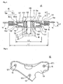
- a vibration proofing heat shield plate 10 is fixed such as to cover at least a part of an exhaust manifold 20 while forming a gap with respect to a surface of the exhaust manifold 20 for reducing a heat radiation from the exhaust manifold 20 of an automotive engine.
- the vibrating proofing heat shield plate 10 is provided with a vibration proofing heat shield plate main body portion 14, a collar member 11 positioned at an open hole of the vibration proofing heat shield plate main body portion 14 and provided with a pair of locking pieces 12 and 13 fastened by bolt to the heat source 20, a washer member 15 in which a portion interposed between a pair of locking pieces 12 and 13 of the collar member 11 is formed in an approximately C-shaped cross section, and a joint member 16 joining the washer member 15 and the vibration proofing heat shield plate main body 14.
- the collar member (11) provided with a pair of locking pieces (12, 13) can be exemplified by a structure having an outer collar member (12) constituted by a circular cylinder member (122) and a collar-shaped locking piece (121) formed in one end of the circular cylinder member (122), and an inner collar member (13) constituted by a circular cylinder member (132) and a collar-shaped locking piece (131) formed in one end of the circular cylinder member (132), in which the outer collar member (12) and the inner collar member (13) are arranged such that another ends of the circular cylinder members are opposed to each other, and are fitted by inserting the circular cylinder members to each other.
- the inner collar member (13) means a partial collar member in which the locking piece is positioned in a heat source side of the vibration proofing heat shield plate main body
- the outer collar member (12) means a partial collar member in which the locking piece is positioned in an opposite side to the heat source of the vibration proofing heat shield plate main body.
- the inner collar member 13 is provided with a circular cylinder member 132 having a bolt hole 171 through which a bolt 17 is inserted, and a collar-shaped locking piece 131 protruding horizontally to an outer side from a lower end portion of the circular cylinder member 132.
- the bolt hole 171 has a diameter which is a little larger than an outer diameter of the bolt 17, whereby the bolt 17 can be inserted with no resistance.
- An upper surface 133 of the locking piece 131 of the inner collar member 13 is formed in a planer shape so as to be brought into contact with a lower member having an approximately C-shaped cross section in the washer member 15.
- a length (a height) of the circular cylinder member 132 of the inner collar member 13 is longer than a length (a height) of a circular cylinder member 122 of the outer collar member 12, and a leading end portion 134 of the circular cylinder member 132 is bent slightly to an outer side.
- the outer collar member 12 is provided with the circular cylinder member 122 having an insertion hole 135 through which the circular cylinder member 132 of the inner collar member 13 is inserted, and a collar-shaped locking piece 121 protruding horizontally to an outer side from an upper end portion of the circular cylinder member 122. It is preferable to set an inner diameter of the insertion hole 135 to a level which is slightly larger than the outer diameter of the circular cylinder member 132 of the inner collar member 13 in view of an easy insertion and a slack prevention.
- a back surface 123 of the locking piece 121 of the outer collar member 12 is formed in a planner shape so as to be brought into contact with the upper member having the approximately C-shaped cross section in the washer member 15.
- a length of the circular cylinder member 122 of the outer collar member 12 is set to such a length that a leading end of the circular cylinder member 122 is brought into contact with the upper surface 133 of the locking piece 131 of the inner collar member 13 in a state in which the vibration proofing heat shield plate 10 is fastened by bolt to the heat source 20. Further, an outer angle of a joint portion between the circular cylinder member 122 and the locking piece 121 is chamfered, and is set in a mating state to the leading end portion of the circular cylinder member 132 of the inner collar member 13.
- a diameter L2 of both the locking pieces 121 and 131 is set to such a level that the approximately C-shaped cross section portion of the washer member 15 can be inserted to a gap between both the locking pieces 121 and 131, and around the circular cylinder member 122 of the outer collar member 12. Further, the gap L3 between both the locking pieces 121 and 131 is set to such a level that the approximately C-shaped cross section portion of the washer member 15 is inserted thereto, and a spring energizing force of the washer member 15 is applied thereto.
- a hole 141 having a diameter L1 to which the collar member 11 or the like is mounted is formed in the vibration proofing heat shield plate main body portion 14.
- the hole 141 is formed at a position opposing to a mounting portion 18 of the exhaust manifold at a time of mounting the vibration proofing heat shield plate 10 to the exhaust manifold.
- a magnitude of the diameter L1 is slightly larger than the diameter of the locking pieces 121 and 131 of the collarmember 11. Accordingly, it is possible to mount the washer member 15 between a pair of locking pieces 121 and 131, and it is possible to join the washer 15 to the vibration proofing heat shield plate main body portion 14 via the joint member 16. Further, a female screw 172 screwed with the bolt 17 is formed in the mounting portion 18 of the exhaust manifold.
- the washer member 15 is structured such that a hole side (an inner side) is formed in an annular shape having an approximately C-shaped cross section, and an outer side is formed in a flat annular shape connected to the annular shape having the approximately C-shaped cross section.
- the washer member 15 is structured, for example, such that two deformed washers each having an upward or downward bent hole side are assembled in a vertically linear symmetric shape by bringing outer annular flat portions into contact with each other.
- the washer member 15 may be constituted by an integral structure in which the annular portions of the flat plates are previously joined, or may be constituted by a structure assembled by simply bringing the annular portions of the flat plates into contact with each other.
- the structure assembled by simply bringing the annular portions of the flat plates into contact with each other is preferable in view that a joining step is not required.
- a material of the washer member 15 can employ a steel material having an elasticity.
- the joint member 16 joining the washer member 15 and the vibration proofing heat shield plate main body portion 14 is not particularly limited, however, employs a ring-like member having an approximately S-shaped cross section in the present embodiment.
- a root portion in a lower side of the approximately S-shaped portion is fitted to an annular flat plate portion 151a of the washer member 15, and a root portion in an upper side of the approximately S-shaped portion is fitted to an open hole edge of the vibration proofing heat shield plate main body portion 14.
- the root portion in the lower side of the approximately S-shaped portion is fitted to the open hole edge of the vibration proofing heat shield plate main body portion 14, and the root portion in the upper side is fitted to the annular flat plate portion 151a of the washer member 15.
- a hole 141 having a diameter L1 is pierced in a predetermined position of the vibration proofing heat shield plate main body portion 14.
- two deformed washers 15a and 15b each having an upward bent inner side are assembled in a vertically linear symmetric shape by bringing annular flat plate portions 151a and 151b into contact with each other, and next, the annular flat portion in the outer side of the washer member 15 is fitted to one root portion of the S-shaped portion of the joint member 16.
- the open hole edge of the vibration proofing heat shield plate main body portion 14 is fitted to another root portion of the S-shaped portion of the joint member 16, and is caulked by pressing the joint member 16 from both the upper and lower sides.
- the inner collar member 13 is applied to the hole formed by attaching the washer member 15 from the back surface. In other words, the upper surface 133 of the locking piece 131 of the inner collar member 13 is brought into contact with the lower member of the approximately C-shaped cross section of the washer member 15.
- the washer member 15 is pinched by a pair of locking pieces 12 and 13 of the collar member 11 by inserting the circular cylinder member 132 of the inner collar member 13 to the insertion hole 135 of the circular cylinder member 122 of the outer collar member 12, whereby the vibration proofing heat shield plate 10 is manufactured.
- the vibration proofing heat shield plate 10 obtained by the method mentioned above is applied, for example, so as to cover all the surface of the exhaust manifold, and next, is fastened by the bolt 17 after finely adjusting a positional relation between the bolt hole 171 of the collar member 11 and the mounting portion 18 of the exhaust manifold 20.
- the collar member 11 and the washer member 15 are stably fixed by fastening the bolt 17, and the collar member 11 and the exhaust manifold 20 are stably fixed thereby (refer to Fig. 1).
- the vibration proofing heat shield plate main body portion 14 is supported to the collar member 11 fixed to the heat source by the spring energizing force of the approximately C-shaped cross section portion of the washer member 15.
- the collar member 11 is constituted by a rigid material, and is not deformed by fastening by bolt. Accordingly, the washer member 15 arranged between a pair of upper and lower locking pieces 121 and 131 does not fall away in spite that it is not fixed by welding.
- the buffering member is constituted by three elements comprising the collar member 11, the washer member 15 and the joint member, that is, the number of the parts is small and the simple structure is obtained, a cost can be reduced. Further, since the vibration from the vibration source can be absorbed by the spring effect of the washer member, a high vibration controlling effect can be obtained. In particular, since the vibration proofing heat shield plate main body portion 14 is not in contact with the collar member 11 even if a lateral vibration is generated, no noise is generated and no damage is generated. Further, the heat conduction from the heat source can be shielded by the washer member, and a high heat shielding effect can be obtained.
Landscapes
- Engineering & Computer Science (AREA)
- Mechanical Engineering (AREA)
- Chemical & Material Sciences (AREA)
- Combustion & Propulsion (AREA)
- General Engineering & Computer Science (AREA)
- Physics & Mathematics (AREA)
- Acoustics & Sound (AREA)
- Exhaust Silencers (AREA)
Applications Claiming Priority (2)
| Application Number | Priority Date | Filing Date | Title |
|---|---|---|---|
| JP2003368453A JP4398222B2 (ja) | 2003-10-29 | 2003-10-29 | 防振遮熱板 |
| JP2003368453 | 2003-10-29 |
Publications (2)
| Publication Number | Publication Date |
|---|---|
| EP1528231A1 EP1528231A1 (en) | 2005-05-04 |
| EP1528231B1 true EP1528231B1 (en) | 2006-08-23 |
Family
ID=34420153
Family Applications (1)
| Application Number | Title | Priority Date | Filing Date |
|---|---|---|---|
| EP04025271A Active EP1528231B1 (en) | 2003-10-29 | 2004-10-25 | Vibration proofing heat shield plate |
Country Status (5)
| Country | Link |
|---|---|
| US (1) | US7273128B2 (ja) |
| EP (1) | EP1528231B1 (ja) |
| JP (1) | JP4398222B2 (ja) |
| KR (1) | KR101101032B1 (ja) |
| DE (1) | DE602004002062T2 (ja) |
Cited By (1)
| Publication number | Priority date | Publication date | Assignee | Title |
|---|---|---|---|---|
| US9133869B2 (en) | 2011-08-01 | 2015-09-15 | Elringklinger Ag | Shielding device with a shielding element and at least one temperature and oscillation-decoupled fastening device |
Families Citing this family (55)
| Publication number | Priority date | Publication date | Assignee | Title |
|---|---|---|---|---|
| DE10253832A1 (de) * | 2002-11-18 | 2004-05-27 | Carcoustics Tech Center Gmbh | Schallisolierender Hitzeschutzschild |
| JP4472325B2 (ja) * | 2003-12-25 | 2010-06-02 | 三和パッキング工業株式会社 | 緩衝装置 |
| JP2006070705A (ja) * | 2004-08-31 | 2006-03-16 | Honda Motor Co Ltd | 車両用エンジンの排気装置 |
| DE102005024864A1 (de) * | 2005-05-31 | 2006-12-28 | Reinz-Dichtungs-Gmbh | Hitzeschild |
| DE102006003229A1 (de) * | 2006-01-24 | 2007-08-02 | Federal-Mogul Sealing Systems Gmbh | Hitzeschild |
| DE102006041105B4 (de) | 2006-09-01 | 2008-08-28 | Audi Ag | Befestigungsvorrichtung für eine Fahrzeugkomponente |
| JP2008069893A (ja) * | 2006-09-14 | 2008-03-27 | Honda Motor Co Ltd | 防音構造 |
| JP4941126B2 (ja) * | 2007-06-27 | 2012-05-30 | 国産部品工業株式会社 | 遮音カバー |
| DE102007041576B4 (de) * | 2007-09-01 | 2010-11-11 | Elringklinger Ag | Anordnung zur Verbindung metallischer Bauteile, nämlich von zwei Dichtungslagen einer zweiteiligen Dichtungsanordnung |
| KR100998180B1 (ko) | 2007-12-31 | 2010-12-03 | 우신공업 주식회사 | 아이솔레이터 |
| KR200447395Y1 (ko) * | 2008-02-29 | 2010-01-25 | (주)마이크로컨텍솔루션 | 히트 프로텍터의 고정유닛 구조 |
| DE102009012383A1 (de) | 2009-03-09 | 2010-09-23 | Federal-Mogul Sealing Systems Gmbh | Temperatur-Schwingungsentkoppelelement |
| WO2011021495A1 (ja) * | 2009-08-17 | 2011-02-24 | 三和パッキング工業株式会社 | 緩衝装置及び金属製カバー |
| DE202010013507U1 (de) * | 2009-09-23 | 2011-02-10 | Reinz-Dichtungs-Gmbh | Hitzeschild |
| JP2010025348A (ja) * | 2009-11-02 | 2010-02-04 | Sanwa Packing Kogyo Co Ltd | 結合部材 |
| CN102192010B (zh) * | 2010-03-03 | 2013-06-19 | 株式会社神户制钢所 | 遮音构造以及遮音盖 |
| JP5566848B2 (ja) * | 2010-03-03 | 2014-08-06 | 株式会社神戸製鋼所 | 遮音構造および遮音カバー |
| DE102010018345A1 (de) * | 2010-04-27 | 2011-10-27 | Bayerische Motoren Werke Aktiengesellschaft | Baugruppe zur Befestigung eines Abgaskrümmers an einem Zylinderkopf sowie Motoreinheit |
| TWI386561B (zh) * | 2010-05-26 | 2013-02-21 | Hannstar Display Corp | 具有鎖定裝置的固定結構 |
| CN102947134B (zh) * | 2010-06-16 | 2015-09-02 | 夏伊洛工业公司 | 面板组件以及形成面板组件的方法 |
| JP4901992B1 (ja) | 2010-12-22 | 2012-03-21 | 三和パッキング工業株式会社 | 緩衝装置及び金属製カバー |
| JP2012149698A (ja) * | 2011-01-19 | 2012-08-09 | Sanwa Packing Kogyo Co Ltd | カラー部材、緩衝装置並びに金属製カバー |
| CN102146834A (zh) * | 2011-02-10 | 2011-08-10 | 重庆长安汽车股份有限公司 | 一种增压汽油发动机用铸铁排气歧管 |
| DE102011082132A1 (de) * | 2011-09-05 | 2013-03-07 | Federal-Mogul Sealing Systems Gmbh | Wärmeabschirmkörper mit temperaturfesten Befestigungsstellen und Verfahren zu dessen Herstellung |
| JP5661581B2 (ja) * | 2011-09-07 | 2015-01-28 | 株式会社神戸製鋼所 | 遮音カバー |
| DE102011082936A1 (de) * | 2011-09-19 | 2013-03-21 | Federal-Mogul Sealing Systems Gmbh | Befestigungselement für ein Abschirmteil und Abschirmteil mit Befestigungselement |
| KR101402725B1 (ko) * | 2011-10-14 | 2014-06-17 | (주)마이크로컨텍솔루션 | 와이어 그로밋 조립부재를 갖는 히트 프로텍터 조립체 및 그 조립방법 |
| JP5792674B2 (ja) * | 2012-04-24 | 2015-10-14 | 株式会社神戸製鋼所 | 遮音カバーの取付構造 |
| JP5697698B2 (ja) * | 2013-03-05 | 2015-04-08 | 富士重工業株式会社 | エンジン搭載機器のエンジンマウント構造 |
| DE102013204732A1 (de) * | 2013-03-18 | 2014-09-18 | Eberspächer Exhaust Technology GmbH & Co. KG | Isolierung |
| JP5885258B2 (ja) * | 2013-05-21 | 2016-03-15 | トヨタ自動車株式会社 | ヒートインシュレータの締結構造 |
| JP5922620B2 (ja) * | 2013-06-20 | 2016-05-24 | 株式会社ユタカ技研 | 排気系部品への遮熱カバーの防振取り付け構造 |
| DE202014003108U1 (de) * | 2014-04-11 | 2015-04-15 | Reinz-Dichtungs-Gmbh | Hitzeschild |
| JP6263799B2 (ja) * | 2014-09-30 | 2018-01-24 | 本田技研工業株式会社 | 車両用内燃機関における排気系構造 |
| DE102015100994A1 (de) * | 2015-01-23 | 2016-07-28 | Faurecia Emissions Control Technologies, Germany Gmbh | Hitzeschildbaugruppe für eine Fahrzeugabgasanlage sowie Abgasanlagenbauteil eines Kraftfahrzeugs |
| JP6370723B2 (ja) * | 2015-01-30 | 2018-08-08 | ニチアス株式会社 | 連結具及び遮蔽体 |
| US9964175B2 (en) * | 2015-04-24 | 2018-05-08 | Federal-Mogul Llc | Heat and vibration mounting isolator for a heat shield, heat shield assembly and method of construction thereof |
| KR102039845B1 (ko) * | 2015-10-09 | 2019-11-01 | 니찌아스 카부시키카이샤 | 연결구 |
| CN106812579A (zh) * | 2015-12-02 | 2017-06-09 | 光阳工业股份有限公司 | 引擎排气管保护盖的固定结构 |
| CN108474284B (zh) * | 2015-12-28 | 2020-11-27 | 莱多公司 | 具有保持特征的热屏蔽件 |
| DE102016106153A1 (de) * | 2016-04-05 | 2017-10-05 | Elringklinger Ag | Abschirmteil, insbesondere Hitzeschild mit einer Befestigungsvorrichtung zum Befestigen des Abschirmteiles an einem Befestigungspartnerteil |
| DE102016106152A1 (de) | 2016-04-05 | 2017-10-05 | Elringklinger Ag | Befestigungsvorrichtung für eine Entkopplungsvorrichtung an einem Abschirmteil, Entkopplungsvorrichtung aufweisend die Befestigungsvorrichtung sowie Abschirmteil aufweisend die Entkopplungsvorrichtung |
| DE102016106150A1 (de) * | 2016-04-05 | 2017-10-05 | Elringklinger Ag | Befestigungsvorrichtung für ein Abschirmteil, insbesondere für ein Hitzeschild sowie Abschirmteil aufweisend zumindest eine Befestigungsvorrichtung |
| DE102016106151A1 (de) * | 2016-04-05 | 2017-10-05 | Elringklinger Ag | Befestigungsvorrichtung für ein Abschirmteil zur schwingungsentkoppelnden Befestigung des Abschirmteils an einem Befestigungspartnerteil sowie Abschirmteil aufweisend Befestigungsvorrichtung |
| DE202016102795U1 (de) * | 2016-05-25 | 2017-08-28 | Reinz-Dichtungs-Gmbh | Abschirmvorrichtung |
| US10457226B2 (en) * | 2016-07-22 | 2019-10-29 | Ford Global Technologies, Llc | Acoustical absorber having a body and at least one serrated washer |
| FR3065488B1 (fr) * | 2017-04-20 | 2019-06-28 | Faurecia Systemes D'echappement | Element de ligne d'echappement et procede de fabrication d'un tel element |
| DE102017126241A1 (de) * | 2017-11-09 | 2019-05-09 | Man Truck & Bus Ag | Hitzeschildbefestigung |
| US20190172441A1 (en) * | 2017-12-05 | 2019-06-06 | GM Global Technology Operations LLC | Passive sound enhancement system for a vehicle |
| DE102019111078A1 (de) | 2019-04-29 | 2020-10-29 | Böllhoff Verbindungstechnik GmbH | Befestigungsanordnung mit Dämpfungswirkung und Bauteilverbindung mit der Befestigungsanordnung |
| KR102179977B1 (ko) * | 2020-02-06 | 2020-11-17 | 주식회사 한텍테크놀로지 | 방열커버 마모 방지 기능이 구비된 배기다기관 방열커버 결합장치 |
| DE102020128549A1 (de) * | 2020-10-29 | 2022-05-05 | Böllhoff Verbindungstechnik GmbH | Dämpfungsanordnung, Bauteil mit Dämpfungsanordnung sowie entsprechende Bauteilverbindung, ein Herstellungsverfahren und ein Verbindungsverfahren |
| CN112594530B (zh) * | 2020-12-17 | 2022-08-16 | 浙江枫宸光电科技有限公司 | 一种led显示屏调节支架 |
| DE102022110271A1 (de) | 2022-04-27 | 2023-11-02 | Böllhoff Verbindungstechnik GmbH | Dämpfungsanordnung, Bauteil mit Dämpfungsanordnung, entsprechende Bauteilverbindung, Verbindungsverfahren und Herstellungsverfahren |
| CN115251686B (zh) * | 2022-09-14 | 2024-03-01 | 浙江武义万家隆塑业有限公司 | 一种电热超声波清洗冰激凌勺 |
Family Cites Families (25)
| Publication number | Priority date | Publication date | Assignee | Title |
|---|---|---|---|---|
| US1935364A (en) * | 1930-09-19 | 1933-11-14 | Langen Heinrich | Spring |
| US1941763A (en) * | 1932-09-29 | 1934-01-02 | Borg Warner | Torque stabilizer spring |
| US2432717A (en) * | 1944-08-16 | 1947-12-16 | Cons Vuitee Aircraft Corp | Washer type compression spring with tubular or sheathlike elastic covering |
| NL228068A (ja) * | 1958-05-23 | |||
| US3028138A (en) * | 1958-08-06 | 1962-04-03 | Wells & Company Ltd A | Anti-vibration mountings |
| US3107905A (en) * | 1960-10-19 | 1963-10-22 | Charles D Lucas | Belleville spring elastic suspension |
| DE1171932B (de) * | 1963-04-27 | 1964-06-11 | Klein Schanzlin & Becker Ag | Thermostatisch gesteuerter Dampfwasserableiter |
| US3279779A (en) * | 1964-07-20 | 1966-10-18 | Lord Corp | Combined disc and elastomeric spring |
| US3489402A (en) * | 1966-08-22 | 1970-01-13 | Btr Industries Ltd | Composite elastomeric springs |
| US3508020A (en) * | 1968-03-18 | 1970-04-21 | Southwestern Ind Inc | Linearization of negative spring rate systems |
| JPS5617313A (en) | 1979-07-20 | 1981-02-19 | Canon Inc | Zoom lens barrel |
| JP2749710B2 (ja) | 1990-07-13 | 1998-05-13 | 株式会社アマダ | パンチプレス |
| JP3490927B2 (ja) * | 1999-05-19 | 2004-01-26 | ニチアス株式会社 | 熱遮蔽板に振動フローティングワッシャを取付ける方法 |
| US6318734B1 (en) * | 1999-12-21 | 2001-11-20 | Dana Corporation | Gasket with integral support |
| DE10021575C2 (de) * | 2000-05-03 | 2002-09-19 | Elringklinger Ag | Vorrichtung zur akustisch entkoppelten Befestigung von Hitzeschildern oder ähnlichen leicht schwingfähigen Bauteilen |
| JP2002113525A (ja) | 2000-10-04 | 2002-04-16 | Sanwa Packing Kogyo Co Ltd | 金属製カバー、その製造方法及びそれに用いるプレス用金型 |
| JP2002235800A (ja) * | 2001-02-13 | 2002-08-23 | Sanwa Packing Kogyo Co Ltd | 緩衝装置 |
| JP3669932B2 (ja) | 2001-03-12 | 2005-07-13 | 日本ラインツ株式会社 | 遮熱板用支持装置の緩衝材 |
| DE10114295B4 (de) * | 2001-03-23 | 2010-02-25 | Reinz-Dichtungs-Gmbh | Hitzeschildbefestigungselement |
| US6581720B1 (en) * | 2001-11-30 | 2003-06-24 | Dana Corporation | Noise attenuating insulated heat shield |
| JP2004092543A (ja) * | 2002-08-30 | 2004-03-25 | Sanwa Packing Kogyo Co Ltd | カバー装置 |
| US6786298B1 (en) * | 2003-05-13 | 2004-09-07 | Compal Electronics Inc. | Vibration-absorbing structure for support section of a self-vibratory electronic member |
| JP2005030571A (ja) * | 2003-07-11 | 2005-02-03 | Nichias Corp | 緩衝ワッシャ部材及びこれを備える防振遮熱板 |
| JP2005030570A (ja) * | 2003-07-11 | 2005-02-03 | Nichias Corp | 防振遮熱板 |
| JP4472325B2 (ja) * | 2003-12-25 | 2010-06-02 | 三和パッキング工業株式会社 | 緩衝装置 |
-
2003
- 2003-10-29 JP JP2003368453A patent/JP4398222B2/ja not_active Expired - Lifetime
-
2004
- 2004-10-22 KR KR1020040084842A patent/KR101101032B1/ko active IP Right Grant
- 2004-10-25 US US10/971,134 patent/US7273128B2/en active Active
- 2004-10-25 EP EP04025271A patent/EP1528231B1/en active Active
- 2004-10-25 DE DE602004002062T patent/DE602004002062T2/de active Active
Cited By (2)
| Publication number | Priority date | Publication date | Assignee | Title |
|---|---|---|---|---|
| US9133869B2 (en) | 2011-08-01 | 2015-09-15 | Elringklinger Ag | Shielding device with a shielding element and at least one temperature and oscillation-decoupled fastening device |
| US9856904B2 (en) | 2011-08-01 | 2018-01-02 | Elringklinger Ag | Shielding device with a shielding element and at least one temperature and oscillation-decoupled fastening device |
Also Published As
| Publication number | Publication date |
|---|---|
| EP1528231A1 (en) | 2005-05-04 |
| JP2005133594A (ja) | 2005-05-26 |
| DE602004002062T2 (de) | 2007-01-18 |
| JP4398222B2 (ja) | 2010-01-13 |
| DE602004002062D1 (de) | 2006-10-05 |
| US20050139416A1 (en) | 2005-06-30 |
| KR20050040727A (ko) | 2005-05-03 |
| US7273128B2 (en) | 2007-09-25 |
| KR101101032B1 (ko) | 2011-12-29 |
Similar Documents
| Publication | Publication Date | Title |
|---|---|---|
| EP1528231B1 (en) | Vibration proofing heat shield plate | |
| US9827909B2 (en) | Exterior rear view mirror and process for its assembly | |
| JP2005030570A (ja) | 防振遮熱板 | |
| JP2004225900A (ja) | 二部品からなる内部トリムリテーナ | |
| CA2393434C (en) | Vehicle component mounting assembly | |
| KR102105835B1 (ko) | 어스단자의 조립구조 | |
| US6640881B2 (en) | Holding assembly for the attachment of an exhaust gas heat exchanger | |
| CN113853311A (zh) | 用于减震器的阻尼器轴承的轴承组件以及用于在车辆车身处装配阻尼器轴承的方法 | |
| KR102510724B1 (ko) | 차량 배기 시스템용 열차폐 조립체 및 자동차의 배기 시스템 구성요소 | |
| KR20190064723A (ko) | 자동차용 변속기 마운트 | |
| KR101402725B1 (ko) | 와이어 그로밋 조립부재를 갖는 히트 프로텍터 조립체 및 그 조립방법 | |
| US6668955B1 (en) | Methods and apparatus for mounting a heat exchanger to a vehicle | |
| JP2012067873A (ja) | ボルト穴保護部材 | |
| EP1291537B1 (en) | A housing assembly | |
| JP2002061231A (ja) | ハンドレール装置 | |
| CN210126565U (zh) | 隔热体安装结构 | |
| KR101976491B1 (ko) | 캐니스터 장착구조 | |
| US20220111911A1 (en) | Chassis component with at least one connecting section for connecting to a mounting section of a chassis element | |
| JP2006160086A (ja) | 車両用熱交換器の取付構造 | |
| EP3760855A1 (en) | Connection assembly for a device | |
| JP2006188975A (ja) | 内燃機関の熱防護装置 | |
| TW202227294A (zh) | 繩索鈎 | |
| US20090200433A1 (en) | Mounting flange configuration for exhaust component | |
| JPH0425418Y2 (ja) | ||
| JP2020029219A (ja) | ミラー取付構造 |
Legal Events
| Date | Code | Title | Description |
|---|---|---|---|
| PUAI | Public reference made under article 153(3) epc to a published international application that has entered the european phase |
Free format text: ORIGINAL CODE: 0009012 |
|
| AK | Designated contracting states |
Kind code of ref document: A1 Designated state(s): AT BE BG CH CY CZ DE DK EE ES FI FR GB GR HU IE IT LI LU MC NL PL PT RO SE SI SK TR |
|
| AX | Request for extension of the european patent |
Extension state: AL HR LT LV MK |
|
| 17P | Request for examination filed |
Effective date: 20051017 |
|
| AKX | Designation fees paid |
Designated state(s): DE FR GB |
|
| GRAP | Despatch of communication of intention to grant a patent |
Free format text: ORIGINAL CODE: EPIDOSNIGR1 |
|
| GRAS | Grant fee paid |
Free format text: ORIGINAL CODE: EPIDOSNIGR3 |
|
| GRAA | (expected) grant |
Free format text: ORIGINAL CODE: 0009210 |
|
| AK | Designated contracting states |
Kind code of ref document: B1 Designated state(s): DE FR GB |
|
| REG | Reference to a national code |
Ref country code: GB Ref legal event code: FG4D |
|
| REF | Corresponds to: |
Ref document number: 602004002062 Country of ref document: DE Date of ref document: 20061005 Kind code of ref document: P |
|
| ET | Fr: translation filed | ||
| PLBE | No opposition filed within time limit |
Free format text: ORIGINAL CODE: 0009261 |
|
| STAA | Information on the status of an ep patent application or granted ep patent |
Free format text: STATUS: NO OPPOSITION FILED WITHIN TIME LIMIT |
|
| 26N | No opposition filed |
Effective date: 20070524 |
|
| REG | Reference to a national code |
Ref country code: FR Ref legal event code: PLFP Year of fee payment: 13 |
|
| REG | Reference to a national code |
Ref country code: FR Ref legal event code: PLFP Year of fee payment: 14 |
|
| REG | Reference to a national code |
Ref country code: FR Ref legal event code: PLFP Year of fee payment: 15 |
|
| P01 | Opt-out of the competence of the unified patent court (upc) registered |
Effective date: 20230512 |
|
| PGFP | Annual fee paid to national office [announced via postgrant information from national office to epo] |
Ref country code: GB Payment date: 20230831 Year of fee payment: 20 |
|
| PGFP | Annual fee paid to national office [announced via postgrant information from national office to epo] |
Ref country code: FR Payment date: 20230911 Year of fee payment: 20 |
|
| PGFP | Annual fee paid to national office [announced via postgrant information from national office to epo] |
Ref country code: DE Payment date: 20230830 Year of fee payment: 20 |