EP1528231B1 - Vibration proofing heat shield plate - Google Patents
Vibration proofing heat shield plate Download PDFInfo
- Publication number
- EP1528231B1 EP1528231B1 EP04025271A EP04025271A EP1528231B1 EP 1528231 B1 EP1528231 B1 EP 1528231B1 EP 04025271 A EP04025271 A EP 04025271A EP 04025271 A EP04025271 A EP 04025271A EP 1528231 B1 EP1528231 B1 EP 1528231B1
- Authority
- EP
- European Patent Office
- Prior art keywords
- shield plate
- heat shield
- vibration proofing
- vibration
- heat
- Prior art date
- Legal status (The legal status is an assumption and is not a legal conclusion. Google has not performed a legal analysis and makes no representation as to the accuracy of the status listed.)
- Active
Links
- 230000005855 radiation Effects 0.000 claims description 4
- 230000000694 effects Effects 0.000 description 8
- 238000000034 method Methods 0.000 description 5
- 230000003139 buffering effect Effects 0.000 description 4
- 238000003780 insertion Methods 0.000 description 4
- 230000037431 insertion Effects 0.000 description 4
- 239000002184 metal Substances 0.000 description 4
- 239000000463 material Substances 0.000 description 3
- 230000001276 controlling effect Effects 0.000 description 2
- 230000013011 mating Effects 0.000 description 2
- 229910000831 Steel Inorganic materials 0.000 description 1
- 238000002485 combustion reaction Methods 0.000 description 1
- 238000003825 pressing Methods 0.000 description 1
- 230000002265 prevention Effects 0.000 description 1
- 239000010959 steel Substances 0.000 description 1
- 238000003466 welding Methods 0.000 description 1
Images

Classifications
-
- F—MECHANICAL ENGINEERING; LIGHTING; HEATING; WEAPONS; BLASTING
- F01—MACHINES OR ENGINES IN GENERAL; ENGINE PLANTS IN GENERAL; STEAM ENGINES
- F01N—GAS-FLOW SILENCERS OR EXHAUST APPARATUS FOR MACHINES OR ENGINES IN GENERAL; GAS-FLOW SILENCERS OR EXHAUST APPARATUS FOR INTERNAL COMBUSTION ENGINES
- F01N13/00—Exhaust or silencing apparatus characterised by constructional features ; Exhaust or silencing apparatus, or parts thereof, having pertinent characteristics not provided for in, or of interest apart from, groups F01N1/00 - F01N5/00, F01N9/00, F01N11/00
- F01N13/18—Construction facilitating manufacture, assembly, or disassembly
- F01N13/1838—Construction facilitating manufacture, assembly, or disassembly characterised by the type of connection between parts of exhaust or silencing apparatus, e.g. between housing and tubes, between tubes and baffles
- F01N13/1844—Mechanical joints
- F01N13/1855—Mechanical joints the connection being realised by using bolts, screws, rivets or the like
-
- B—PERFORMING OPERATIONS; TRANSPORTING
- B60—VEHICLES IN GENERAL
- B60R—VEHICLES, VEHICLE FITTINGS, OR VEHICLE PARTS, NOT OTHERWISE PROVIDED FOR
- B60R13/00—Elements for body-finishing, identifying, or decorating; Arrangements or adaptations for advertising purposes
- B60R13/08—Insulating elements, e.g. for sound insulation
- B60R13/0876—Insulating elements, e.g. for sound insulation for mounting around heat sources, e.g. exhaust pipes
-
- F—MECHANICAL ENGINEERING; LIGHTING; HEATING; WEAPONS; BLASTING
- F01—MACHINES OR ENGINES IN GENERAL; ENGINE PLANTS IN GENERAL; STEAM ENGINES
- F01N—GAS-FLOW SILENCERS OR EXHAUST APPARATUS FOR MACHINES OR ENGINES IN GENERAL; GAS-FLOW SILENCERS OR EXHAUST APPARATUS FOR INTERNAL COMBUSTION ENGINES
- F01N13/00—Exhaust or silencing apparatus characterised by constructional features ; Exhaust or silencing apparatus, or parts thereof, having pertinent characteristics not provided for in, or of interest apart from, groups F01N1/00 - F01N5/00, F01N9/00, F01N11/00
- F01N13/08—Other arrangements or adaptations of exhaust conduits
- F01N13/10—Other arrangements or adaptations of exhaust conduits of exhaust manifolds
- F01N13/102—Other arrangements or adaptations of exhaust conduits of exhaust manifolds having thermal insulation
-
- F—MECHANICAL ENGINEERING; LIGHTING; HEATING; WEAPONS; BLASTING
- F01—MACHINES OR ENGINES IN GENERAL; ENGINE PLANTS IN GENERAL; STEAM ENGINES
- F01N—GAS-FLOW SILENCERS OR EXHAUST APPARATUS FOR MACHINES OR ENGINES IN GENERAL; GAS-FLOW SILENCERS OR EXHAUST APPARATUS FOR INTERNAL COMBUSTION ENGINES
- F01N13/00—Exhaust or silencing apparatus characterised by constructional features ; Exhaust or silencing apparatus, or parts thereof, having pertinent characteristics not provided for in, or of interest apart from, groups F01N1/00 - F01N5/00, F01N9/00, F01N11/00
- F01N13/14—Exhaust or silencing apparatus characterised by constructional features ; Exhaust or silencing apparatus, or parts thereof, having pertinent characteristics not provided for in, or of interest apart from, groups F01N1/00 - F01N5/00, F01N9/00, F01N11/00 having thermal insulation
-
- F—MECHANICAL ENGINEERING; LIGHTING; HEATING; WEAPONS; BLASTING
- F01—MACHINES OR ENGINES IN GENERAL; ENGINE PLANTS IN GENERAL; STEAM ENGINES
- F01N—GAS-FLOW SILENCERS OR EXHAUST APPARATUS FOR MACHINES OR ENGINES IN GENERAL; GAS-FLOW SILENCERS OR EXHAUST APPARATUS FOR INTERNAL COMBUSTION ENGINES
- F01N13/00—Exhaust or silencing apparatus characterised by constructional features ; Exhaust or silencing apparatus, or parts thereof, having pertinent characteristics not provided for in, or of interest apart from, groups F01N1/00 - F01N5/00, F01N9/00, F01N11/00
- F01N13/18—Construction facilitating manufacture, assembly, or disassembly
- F01N13/1805—Fixing exhaust manifolds, exhaust pipes or pipe sections to each other, to engine or to vehicle body
- F01N13/1811—Fixing exhaust manifolds, exhaust pipes or pipe sections to each other, to engine or to vehicle body with means permitting relative movement, e.g. compensation of thermal expansion or vibration
-
- F—MECHANICAL ENGINEERING; LIGHTING; HEATING; WEAPONS; BLASTING
- F02—COMBUSTION ENGINES; HOT-GAS OR COMBUSTION-PRODUCT ENGINE PLANTS
- F02B—INTERNAL-COMBUSTION PISTON ENGINES; COMBUSTION ENGINES IN GENERAL
- F02B77/00—Component parts, details or accessories, not otherwise provided for
- F02B77/11—Thermal or acoustic insulation
-
- F—MECHANICAL ENGINEERING; LIGHTING; HEATING; WEAPONS; BLASTING
- F01—MACHINES OR ENGINES IN GENERAL; ENGINE PLANTS IN GENERAL; STEAM ENGINES
- F01N—GAS-FLOW SILENCERS OR EXHAUST APPARATUS FOR MACHINES OR ENGINES IN GENERAL; GAS-FLOW SILENCERS OR EXHAUST APPARATUS FOR INTERNAL COMBUSTION ENGINES
- F01N2450/00—Methods or apparatus for fitting, inserting or repairing different elements
- F01N2450/24—Methods or apparatus for fitting, inserting or repairing different elements by bolts, screws, rivets or the like
Definitions
- the present invention relates to a vibration proofing heat shield plate, for example, arranged around an exhaust manifold of an automotive engine.
- a combustion exhaust gas having a high temperature reaching some hundreds of degree flows through an inner portion of an exhaust manifold 101 of an automotive engine 100 in accordance with an operation of the engine 100. Accordingly, in order to prevent heat and vibration generated from the exhaust manifold 101 from being radiated into an engine room and an external portion of a vehicle, a vibration proofing heat shield plate 102 is provided around the exhaust manifold 101.
- a vibration proofing heat shield plate 102 is provided around the exhaust manifold 101.
- a heat-shield attachement element with a through-hole tor an attachement element is disclosed in US2002/0154484A1 wherein the heat-shield attachement element is formed from at least one flanged tube and another element is provided with a flange Since there is a through-hole in the flanged tube and the other element the flanged tube is inserted in a hole formed in the heat-shield and the flange of the flanged tube contact one side of the heat-shield and the other element contact the opposite side of the heat-shield over an area.
- This heat-shield attachement can be manufactured with a cost-effective procedure. The mechanical loading of the heat-shield is reduced in the attachement region. However this heat-shield attachement can not be easily applied to a exhaust manifold generating noise and lateral vibrations.
- Japanese Unexamined Utility Model Publication No. 56-17313 there is disclosed a heat shield plate in which a wire mesh member is arranged in a mounting portion to a vibration source, and the wire mesh member is integrally joined to a heat resisting metal plate.
- Japanese Unexamined Utility Model Publication No. 4-71733 there is disclosed a heat shield plate in which the heat shield plate is constituted by inner and outer metal plates, and a heat resisting mesh interposed between the metal plates approximately all around an entire surface, the mesh is exposed by notching the metal plate around a mounting portion of the heat shield plate, and the mesh in the exposed portion is mounted to a fixed member.
- a heat shield plate in which two rigid members each having a flange member (a locking piece) protruding to a horizontally outer side from one end of a circular cylinder member (sleeve) are prepared, a collar member is structured by bringing another ends of the circular cylinder members into contact with each other, and a wire mesh member in which holes being larger than an outer diameter of the circular cylinder member and smaller than an outer diameter of the flange member are pierced, is mounted to the circular cylinder member in a loosely fitted state.
- the collar member is strongly fastened by bolt to a predetermined fixed place of the vibration source, the joint between the collar member and the wire mesh member is achieved in the loosely fitted state, and the contact portion between both the elements is partly formed and fluctuated, so that a heat shielding effect is high.
- the collar member and the wire mesh member come into collision with each other due to a lateral vibration of the exhaust manifold, whereby there are generated problems that a noise is generated and the wire mesh member is damaged.
- an object of the present invention is to provide a vibration proofing heat shield plate in which no noise is generated by vibration of the exhaust manifold, and a heat shielding effect and a vibration proofing effect are high.
- the present invention solves the conventional problems mentioned above, and provides a vibration proofing heat shield plate fixed such as to cover at least a part of a heat source fixed to a vibration source while forming a gap with respect to a surface of the heat source for reducing a heat radiation from the heat source, comprising:
- the vibration proofing heat shield plate on the basis of the present invention, no noise is generated by the vibration from the vibration source, and the vibration can be absorbed by the washer member so as to achieve a high vibration controlling effect. Further, since the contact between the heat source and the washer member is mainly achieved by a linear contact, a thermal conduction is shielded and a high heat shielding effect can be obtained.
- a vibration source can be exemplified by a motor vehicle and an exhaust manifold attached to the motor vehicle. Further, a heat source can be exemplified by the exhaust manifold of the motor vehicle.
- a vibration proofing heat shield plate 10 is fixed such as to cover at least a part of an exhaust manifold 20 while forming a gap with respect to a surface of the exhaust manifold 20 for reducing a heat radiation from the exhaust manifold 20 of an automotive engine.
- the vibrating proofing heat shield plate 10 is provided with a vibration proofing heat shield plate main body portion 14, a collar member 11 positioned at an open hole of the vibration proofing heat shield plate main body portion 14 and provided with a pair of locking pieces 12 and 13 fastened by bolt to the heat source 20, a washer member 15 in which a portion interposed between a pair of locking pieces 12 and 13 of the collar member 11 is formed in an approximately C-shaped cross section, and a joint member 16 joining the washer member 15 and the vibration proofing heat shield plate main body 14.
- the collar member (11) provided with a pair of locking pieces (12, 13) can be exemplified by a structure having an outer collar member (12) constituted by a circular cylinder member (122) and a collar-shaped locking piece (121) formed in one end of the circular cylinder member (122), and an inner collar member (13) constituted by a circular cylinder member (132) and a collar-shaped locking piece (131) formed in one end of the circular cylinder member (132), in which the outer collar member (12) and the inner collar member (13) are arranged such that another ends of the circular cylinder members are opposed to each other, and are fitted by inserting the circular cylinder members to each other.
- the inner collar member (13) means a partial collar member in which the locking piece is positioned in a heat source side of the vibration proofing heat shield plate main body
- the outer collar member (12) means a partial collar member in which the locking piece is positioned in an opposite side to the heat source of the vibration proofing heat shield plate main body.
- the inner collar member 13 is provided with a circular cylinder member 132 having a bolt hole 171 through which a bolt 17 is inserted, and a collar-shaped locking piece 131 protruding horizontally to an outer side from a lower end portion of the circular cylinder member 132.
- the bolt hole 171 has a diameter which is a little larger than an outer diameter of the bolt 17, whereby the bolt 17 can be inserted with no resistance.
- An upper surface 133 of the locking piece 131 of the inner collar member 13 is formed in a planer shape so as to be brought into contact with a lower member having an approximately C-shaped cross section in the washer member 15.
- a length (a height) of the circular cylinder member 132 of the inner collar member 13 is longer than a length (a height) of a circular cylinder member 122 of the outer collar member 12, and a leading end portion 134 of the circular cylinder member 132 is bent slightly to an outer side.
- the outer collar member 12 is provided with the circular cylinder member 122 having an insertion hole 135 through which the circular cylinder member 132 of the inner collar member 13 is inserted, and a collar-shaped locking piece 121 protruding horizontally to an outer side from an upper end portion of the circular cylinder member 122. It is preferable to set an inner diameter of the insertion hole 135 to a level which is slightly larger than the outer diameter of the circular cylinder member 132 of the inner collar member 13 in view of an easy insertion and a slack prevention.
- a back surface 123 of the locking piece 121 of the outer collar member 12 is formed in a planner shape so as to be brought into contact with the upper member having the approximately C-shaped cross section in the washer member 15.
- a length of the circular cylinder member 122 of the outer collar member 12 is set to such a length that a leading end of the circular cylinder member 122 is brought into contact with the upper surface 133 of the locking piece 131 of the inner collar member 13 in a state in which the vibration proofing heat shield plate 10 is fastened by bolt to the heat source 20. Further, an outer angle of a joint portion between the circular cylinder member 122 and the locking piece 121 is chamfered, and is set in a mating state to the leading end portion of the circular cylinder member 132 of the inner collar member 13.
- a diameter L2 of both the locking pieces 121 and 131 is set to such a level that the approximately C-shaped cross section portion of the washer member 15 can be inserted to a gap between both the locking pieces 121 and 131, and around the circular cylinder member 122 of the outer collar member 12. Further, the gap L3 between both the locking pieces 121 and 131 is set to such a level that the approximately C-shaped cross section portion of the washer member 15 is inserted thereto, and a spring energizing force of the washer member 15 is applied thereto.
- a hole 141 having a diameter L1 to which the collar member 11 or the like is mounted is formed in the vibration proofing heat shield plate main body portion 14.
- the hole 141 is formed at a position opposing to a mounting portion 18 of the exhaust manifold at a time of mounting the vibration proofing heat shield plate 10 to the exhaust manifold.
- a magnitude of the diameter L1 is slightly larger than the diameter of the locking pieces 121 and 131 of the collarmember 11. Accordingly, it is possible to mount the washer member 15 between a pair of locking pieces 121 and 131, and it is possible to join the washer 15 to the vibration proofing heat shield plate main body portion 14 via the joint member 16. Further, a female screw 172 screwed with the bolt 17 is formed in the mounting portion 18 of the exhaust manifold.
- the washer member 15 is structured such that a hole side (an inner side) is formed in an annular shape having an approximately C-shaped cross section, and an outer side is formed in a flat annular shape connected to the annular shape having the approximately C-shaped cross section.
- the washer member 15 is structured, for example, such that two deformed washers each having an upward or downward bent hole side are assembled in a vertically linear symmetric shape by bringing outer annular flat portions into contact with each other.
- the washer member 15 may be constituted by an integral structure in which the annular portions of the flat plates are previously joined, or may be constituted by a structure assembled by simply bringing the annular portions of the flat plates into contact with each other.
- the structure assembled by simply bringing the annular portions of the flat plates into contact with each other is preferable in view that a joining step is not required.
- a material of the washer member 15 can employ a steel material having an elasticity.
- the joint member 16 joining the washer member 15 and the vibration proofing heat shield plate main body portion 14 is not particularly limited, however, employs a ring-like member having an approximately S-shaped cross section in the present embodiment.
- a root portion in a lower side of the approximately S-shaped portion is fitted to an annular flat plate portion 151a of the washer member 15, and a root portion in an upper side of the approximately S-shaped portion is fitted to an open hole edge of the vibration proofing heat shield plate main body portion 14.
- the root portion in the lower side of the approximately S-shaped portion is fitted to the open hole edge of the vibration proofing heat shield plate main body portion 14, and the root portion in the upper side is fitted to the annular flat plate portion 151a of the washer member 15.
- a hole 141 having a diameter L1 is pierced in a predetermined position of the vibration proofing heat shield plate main body portion 14.
- two deformed washers 15a and 15b each having an upward bent inner side are assembled in a vertically linear symmetric shape by bringing annular flat plate portions 151a and 151b into contact with each other, and next, the annular flat portion in the outer side of the washer member 15 is fitted to one root portion of the S-shaped portion of the joint member 16.
- the open hole edge of the vibration proofing heat shield plate main body portion 14 is fitted to another root portion of the S-shaped portion of the joint member 16, and is caulked by pressing the joint member 16 from both the upper and lower sides.
- the inner collar member 13 is applied to the hole formed by attaching the washer member 15 from the back surface. In other words, the upper surface 133 of the locking piece 131 of the inner collar member 13 is brought into contact with the lower member of the approximately C-shaped cross section of the washer member 15.
- the washer member 15 is pinched by a pair of locking pieces 12 and 13 of the collar member 11 by inserting the circular cylinder member 132 of the inner collar member 13 to the insertion hole 135 of the circular cylinder member 122 of the outer collar member 12, whereby the vibration proofing heat shield plate 10 is manufactured.
- the vibration proofing heat shield plate 10 obtained by the method mentioned above is applied, for example, so as to cover all the surface of the exhaust manifold, and next, is fastened by the bolt 17 after finely adjusting a positional relation between the bolt hole 171 of the collar member 11 and the mounting portion 18 of the exhaust manifold 20.
- the collar member 11 and the washer member 15 are stably fixed by fastening the bolt 17, and the collar member 11 and the exhaust manifold 20 are stably fixed thereby (refer to Fig. 1).
- the vibration proofing heat shield plate main body portion 14 is supported to the collar member 11 fixed to the heat source by the spring energizing force of the approximately C-shaped cross section portion of the washer member 15.
- the collar member 11 is constituted by a rigid material, and is not deformed by fastening by bolt. Accordingly, the washer member 15 arranged between a pair of upper and lower locking pieces 121 and 131 does not fall away in spite that it is not fixed by welding.
- the buffering member is constituted by three elements comprising the collar member 11, the washer member 15 and the joint member, that is, the number of the parts is small and the simple structure is obtained, a cost can be reduced. Further, since the vibration from the vibration source can be absorbed by the spring effect of the washer member, a high vibration controlling effect can be obtained. In particular, since the vibration proofing heat shield plate main body portion 14 is not in contact with the collar member 11 even if a lateral vibration is generated, no noise is generated and no damage is generated. Further, the heat conduction from the heat source can be shielded by the washer member, and a high heat shielding effect can be obtained.
Landscapes
- Engineering & Computer Science (AREA)
- Mechanical Engineering (AREA)
- Chemical & Material Sciences (AREA)
- Combustion & Propulsion (AREA)
- General Engineering & Computer Science (AREA)
- Physics & Mathematics (AREA)
- Acoustics & Sound (AREA)
- Exhaust Silencers (AREA)
Description
- The present invention relates to a vibration proofing heat shield plate, for example, arranged around an exhaust manifold of an automotive engine.
- As shown in Fig. 3, a combustion exhaust gas having a high temperature reaching some hundreds of degree flows through an inner portion of an
exhaust manifold 101 of anautomotive engine 100 in accordance with an operation of theengine 100. Accordingly, in order to prevent heat and vibration generated from theexhaust manifold 101 from being radiated into an engine room and an external portion of a vehicle, a vibration proofingheat shield plate 102 is provided around theexhaust manifold 101. When directly mounting the vibration proofingheat shield plate 102 to theexhaust manifold 101 by abolt 103, the heat and the vibration of theexhaust manifold 101 are transmitted to the vibration proofingheat shield plate 102, and an effect obtained by placing the vibration proofingheat shield plate 102 is reduced. Accordingly, theexhaust manifold 101 and the vibration proofingheat shield plate 102 are joined via a buffering member (not shown). - A heat-shield attachement element with a through-hole tor an attachement element is disclosed in US2002/0154484A1 wherein the heat-shield attachement element is formed from at least one flanged tube and another element is provided with a flange Since there is a through-hole in the flanged tube and the other element the flanged tube is inserted in a hole formed in the heat-shield and the flange of the flanged tube contact one side of the heat-shield and the other element contact the opposite side of the heat-shield over an area. This heat-shield attachement can be manufactured with a cost-effective procedure. The mechanical loading of the heat-shield is reduced in the attachement region. However this heat-shield attachement can not be easily applied to a exhaust manifold generating noise and lateral vibrations.
- In Japanese Unexamined Utility Model Publication No. 56-17313, there is disclosed a heat shield plate in which a wire mesh member is arranged in a mounting portion to a vibration source, and the wire mesh member is integrally joined to a heat resisting metal plate. In Japanese Unexamined Utility Model Publication No. 4-71733, there is disclosed a heat shield plate in which the heat shield plate is constituted by inner and outer metal plates, and a heat resisting mesh interposed between the metal plates approximately all around an entire surface, the mesh is exposed by notching the metal plate around a mounting portion of the heat shield plate, and the mesh in the exposed portion is mounted to a fixed member. In accordance with the heat shield plate, although it is possible to control a vibration of the vibration source, it is not possible to obtain a sufficient satisfaction for shielding the heat radiation from the exhaust manifold, and it is unstable to mount to the vibration source. As a structure for solving the problem, there has been known a heat shield plate in which two rigid members each having a flange member (a locking piece) protruding to a horizontally outer side from one end of a circular cylinder member (sleeve) are prepared, a collar member is structured by bringing another ends of the circular cylinder members into contact with each other, and a wire mesh member in which holes being larger than an outer diameter of the circular cylinder member and smaller than an outer diameter of the flange member are pierced, is mounted to the circular cylinder member in a loosely fitted state. Tn accordance with the heat shield plate, the collar member is strongly fastened by bolt to a predetermined fixed place of the vibration source, the joint between the collar member and the wire mesh member is achieved in the loosely fitted state, and the contact portion between both the elements is partly formed and fluctuated, so that a heat shielding effect is high.
- However, in the heat shield plate having the high heat shielding effect as mentioned above, the collar member and the wire mesh member come into collision with each other due to a lateral vibration of the exhaust manifold, whereby there are generated problems that a noise is generated and the wire mesh member is damaged.
- Accordingly, an object of the present invention is to provide a vibration proofing heat shield plate in which no noise is generated by vibration of the exhaust manifold, and a heat shielding effect and a vibration proofing effect are high.
- In other words, the present invention solves the conventional problems mentioned above, and provides a vibration proofing heat shield plate fixed such as to cover at least a part of a heat source fixed to a vibration source while forming a gap with respect to a surface of the heat source for reducing a heat radiation from the heat source, comprising:
- a vibration proofing heat shield plate main body portion;
- a collar member positioned at an open hole of the vibration proofing heat shield plate main body portion and provided with a pair of locking pieces fastened by bolt to the heat source;
- a washer member in which a portion interposed between a pair of locking pieces of the collar member is formed in an approximately C-shaped cross section; and
- a joint member joining the washer member and the vibration proofing heat shield plate main body.
- In accordance with the vibration proofing heat shield plate on the basis of the present invention, no noise is generated by the vibration from the vibration source, and the vibration can be absorbed by the washer member so as to achieve a high vibration controlling effect. Further, since the contact between the heat source and the washer member is mainly achieved by a linear contact, a thermal conduction is shielded and a high heat shielding effect can be obtained.
-
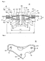
- Fig. 1 is a vertical cross sectional view showing a buffering member portion of a vibration proofing heat shield plate of an embodiment of the present invention;
- Fig. 2 is a view of the vibration proofing heat shield plate of the present embodiment as seen from a front face; and
- Fig. 3 is a view explaining an installing method of a conventional vibration proofing heat shield plate and an exhaust manifold.
- Next, a description will be given of a vibration proofing heat shield plate of an embodiment of the present invention with reference to Figs. 1 and 2. In this case, in the present specification, upper and lower mean upper and lower in the drawings for convenience of explanation.
- In the present invention, a vibration source can be exemplified by a motor vehicle and an exhaust manifold attached to the motor vehicle. Further, a heat source can be exemplified by the exhaust manifold of the motor vehicle. A vibration proofing
heat shield plate 10 is fixed such as to cover at least a part of anexhaust manifold 20 while forming a gap with respect to a surface of theexhaust manifold 20 for reducing a heat radiation from theexhaust manifold 20 of an automotive engine. - The vibrating proofing
heat shield plate 10 is provided with a vibration proofing heat shield platemain body portion 14, acollar member 11 positioned at an open hole of the vibration proofing heat shield platemain body portion 14 and provided with a pair oflocking pieces heat source 20, awasher member 15 in which a portion interposed between a pair oflocking pieces collar member 11 is formed in an approximately C-shaped cross section, and ajoint member 16 joining thewasher member 15 and the vibration proofing heat shield platemain body 14. - In the present invention, the collar member (11) provided with a pair of locking pieces (12, 13) can be exemplified by a structure having an outer collar member (12) constituted by a circular cylinder member (122) and a collar-shaped locking piece (121) formed in one end of the circular cylinder member (122), and an inner collar member (13) constituted by a circular cylinder member (132) and a collar-shaped locking piece (131) formed in one end of the circular cylinder member (132), in which the outer collar member (12) and the inner collar member (13) are arranged such that another ends of the circular cylinder members are opposed to each other, and are fitted by inserting the circular cylinder members to each other. As an aspect that the circular cylinder members are inserted such that another ends of the circular cylinder members are opposed to each other, there can be listed up an aspect that the circular cylinder member of the outer member is inserted to a hole of the circular cylinder member of the inner collar member, and an aspect that the circular cylinder member of the inner collar member is inserted to a hole of the circular cylinder member of the outer collar member. The inner collar member (13) means a partial collar member in which the locking piece is positioned in a heat source side of the vibration proofing heat shield plate main body, and the outer collar member (12) means a partial collar member in which the locking piece is positioned in an opposite side to the heat source of the vibration proofing heat shield plate main body. Further, in a state in which the vibration proofing heat shield plate is fastened by bolt to the heat source (20), it is preferable in view of setting a joint force with the washer member (15) to be proper, to bring an end surface of the circular cylinder member of the collar member (11) having a larger diameter of the circular cylinder member into contact with a back surface of the locking piece (131) of another collar member (132) so as to prevent the washer member (15) from being fastened too excessive. In this case, a leading end portion of the circular cylinder member of the outer collar member (12) or the inner collar member (13) may be bent so as to stabilize mating of the collar members. A description will be given below of an aspect that the circular cylinder member of the inner collar member is inserted to the hole of the circular cylinder member of the outer collar member.
- In Fig. 1, the
inner collar member 13 is provided with acircular cylinder member 132 having abolt hole 171 through which abolt 17 is inserted, and a collar-shaped locking piece 131 protruding horizontally to an outer side from a lower end portion of thecircular cylinder member 132. Thebolt hole 171 has a diameter which is a little larger than an outer diameter of thebolt 17, whereby thebolt 17 can be inserted with no resistance. Anupper surface 133 of thelocking piece 131 of theinner collar member 13 is formed in a planer shape so as to be brought into contact with a lower member having an approximately C-shaped cross section in thewasher member 15. Further, a length (a height) of thecircular cylinder member 132 of theinner collar member 13 is longer than a length (a height) of acircular cylinder member 122 of theouter collar member 12, and a leadingend portion 134 of thecircular cylinder member 132 is bent slightly to an outer side. - The
outer collar member 12 is provided with thecircular cylinder member 122 having aninsertion hole 135 through which thecircular cylinder member 132 of theinner collar member 13 is inserted, and a collar-shaped locking piece 121 protruding horizontally to an outer side from an upper end portion of thecircular cylinder member 122. It is preferable to set an inner diameter of theinsertion hole 135 to a level which is slightly larger than the outer diameter of thecircular cylinder member 132 of theinner collar member 13 in view of an easy insertion and a slack prevention. Aback surface 123 of thelocking piece 121 of theouter collar member 12 is formed in a planner shape so as to be brought into contact with the upper member having the approximately C-shaped cross section in thewasher member 15. A length of thecircular cylinder member 122 of theouter collar member 12 is set to such a length that a leading end of thecircular cylinder member 122 is brought into contact with theupper surface 133 of thelocking piece 131 of theinner collar member 13 in a state in which the vibration proofingheat shield plate 10 is fastened by bolt to theheat source 20. Further, an outer angle of a joint portion between thecircular cylinder member 122 and thelocking piece 121 is chamfered, and is set in a mating state to the leading end portion of thecircular cylinder member 132 of theinner collar member 13. - In the
collar member 11, a diameter L2 of both thelocking pieces washer member 15 can be inserted to a gap between both thelocking pieces circular cylinder member 122 of theouter collar member 12. Further, the gap L3 between both thelocking pieces washer member 15 is inserted thereto, and a spring energizing force of thewasher member 15 is applied thereto. - Known shape and working method can be applied to the vibration proofing heat shield plate
main body portion 14. Ahole 141 having a diameter L1 to which thecollar member 11 or the like is mounted is formed in the vibration proofing heat shield platemain body portion 14. Thehole 141 is formed at a position opposing to a mountingportion 18 of the exhaust manifold at a time of mounting the vibration proofingheat shield plate 10 to the exhaust manifold. A magnitude of the diameter L1 is slightly larger than the diameter of thelocking pieces collarmember 11. Accordingly, it is possible to mount thewasher member 15 between a pair oflocking pieces washer 15 to the vibration proofing heat shield platemain body portion 14 via thejoint member 16. Further, afemale screw 172 screwed with thebolt 17 is formed in themounting portion 18 of the exhaust manifold. - The
washer member 15 is structured such that a hole side (an inner side) is formed in an annular shape having an approximately C-shaped cross section, and an outer side is formed in a flat annular shape connected to the annular shape having the approximately C-shaped cross section. Thewasher member 15 is structured, for example, such that two deformed washers each having an upward or downward bent hole side are assembled in a vertically linear symmetric shape by bringing outer annular flat portions into contact with each other. Accordingly, thewasher member 15 may be constituted by an integral structure in which the annular portions of the flat plates are previously joined, or may be constituted by a structure assembled by simply bringing the annular portions of the flat plates into contact with each other. However, the structure assembled by simply bringing the annular portions of the flat plates into contact with each other is preferable in view that a joining step is not required. A material of thewasher member 15 can employ a steel material having an elasticity. - The
joint member 16 joining thewasher member 15 and the vibration proofing heat shield platemain body portion 14 is not particularly limited, however, employs a ring-like member having an approximately S-shaped cross section in the present embodiment. In other words, a root portion in a lower side of the approximately S-shaped portion is fitted to an annularflat plate portion 151a of thewasher member 15, and a root portion in an upper side of the approximately S-shaped portion is fitted to an open hole edge of the vibration proofing heat shield platemain body portion 14. Further, the root portion in the lower side of the approximately S-shaped portion is fitted to the open hole edge of the vibration proofing heat shield platemain body portion 14, and the root portion in the upper side is fitted to the annularflat plate portion 151a of thewasher member 15. - Next, a description will be given of an example of a method of mounting a buffering member constituted by the
collar member 11, thewasher member 15 and thej oint member 16 to the vibration proofing heat shield platemain body portion 14 with reference to Fig. 1. Ahole 141 having a diameter L1 is pierced in a predetermined position of the vibration proofing heat shield platemain body portion 14. First, twodeformed washers flat plate portions 151a and 151b into contact with each other, and next, the annular flat portion in the outer side of thewasher member 15 is fitted to one root portion of the S-shaped portion of thejoint member 16. Next, the open hole edge of the vibration proofing heat shield platemain body portion 14 is fitted to another root portion of the S-shaped portion of thejoint member 16, and is caulked by pressing thejoint member 16 from both the upper and lower sides. Next, theinner collar member 13 is applied to the hole formed by attaching thewasher member 15 from the back surface. In other words, theupper surface 133 of thelocking piece 131 of theinner collar member 13 is brought into contact with the lower member of the approximately C-shaped cross section of thewasher member 15. Next, thewasher member 15 is pinched by a pair of lockingpieces collar member 11 by inserting thecircular cylinder member 132 of theinner collar member 13 to theinsertion hole 135 of thecircular cylinder member 122 of theouter collar member 12, whereby the vibration proofingheat shield plate 10 is manufactured. The vibration proofingheat shield plate 10 obtained by the method mentioned above is applied, for example, so as to cover all the surface of the exhaust manifold, and next, is fastened by thebolt 17 after finely adjusting a positional relation between thebolt hole 171 of thecollar member 11 and the mountingportion 18 of theexhaust manifold 20. Thecollar member 11 and thewasher member 15 are stably fixed by fastening thebolt 17, and thecollar member 11 and theexhaust manifold 20 are stably fixed thereby (refer to Fig. 1). - The vibration proofing heat shield plate
main body portion 14 is supported to thecollar member 11 fixed to the heat source by the spring energizing force of the approximately C-shaped cross section portion of thewasher member 15. Thecollar member 11 is constituted by a rigid material, and is not deformed by fastening by bolt. Accordingly, thewasher member 15 arranged between a pair of upper andlower locking pieces - In accordance with the vibration proofing
heat shield plate 10 on the basis of the present embodiment, since the buffering member is constituted by three elements comprising thecollar member 11, thewasher member 15 and the joint member, that is, the number of the parts is small and the simple structure is obtained, a cost can be reduced. Further, since the vibration from the vibration source can be absorbed by the spring effect of the washer member, a high vibration controlling effect can be obtained. In particular, since the vibration proofing heat shield platemain body portion 14 is not in contact with thecollar member 11 even if a lateral vibration is generated, no noise is generated and no damage is generated. Further, the heat conduction from the heat source can be shielded by the washer member, and a high heat shielding effect can be obtained.
Claims (3)
- A vibration proofing heat shield plate fixed such as to cover at least a part of a heat source (20) fixed to a vibration source while forming a gap with respect to a surface of said heat source for reducing a heat radiation from the heat source (20), comprising:a vibration proofing heat shield plate main body portion (14)a collar member (11) positioned at an open hole of said vibration proofing heat shield plate main body portion (14) and provided with a pair of locking pieces (12, 13) fastened by bolt to said heat source (20), characterized by:a washer member (15) in which a portion interposed between a pair of the locking pieces (12, 13) of said collar member (11) is formed in an approximately C-shaped cross section; anda joint member (16) joining said washer member (15) and said vibration proofing heat shield plate main body (14).
- A vibration proofing heat shield plate as claimed in claim 1, wherein said washer member (15) is structured by assembling two deformed washers each having an upward or downward bent hole side, in a vertically symmetrical shape by bringing annular flat plate portions in an outer side into contact with each other.
- A vibration proofing heat shield plate as claimed in claim 1 or 2, wherein said heat source (20) is constituted by an exhaust manifold of an automotive engine.
Applications Claiming Priority (2)
| Application Number | Priority Date | Filing Date | Title |
|---|---|---|---|
| JP2003368453A JP4398222B2 (en) | 2003-10-29 | 2003-10-29 | Anti-vibration heat shield |
| JP2003368453 | 2003-10-29 |
Publications (2)
| Publication Number | Publication Date |
|---|---|
| EP1528231A1 EP1528231A1 (en) | 2005-05-04 |
| EP1528231B1 true EP1528231B1 (en) | 2006-08-23 |
Family
ID=34420153
Family Applications (1)
| Application Number | Title | Priority Date | Filing Date |
|---|---|---|---|
| EP04025271A Active EP1528231B1 (en) | 2003-10-29 | 2004-10-25 | Vibration proofing heat shield plate |
Country Status (5)
| Country | Link |
|---|---|
| US (1) | US7273128B2 (en) |
| EP (1) | EP1528231B1 (en) |
| JP (1) | JP4398222B2 (en) |
| KR (1) | KR101101032B1 (en) |
| DE (1) | DE602004002062T2 (en) |
Cited By (1)
| Publication number | Priority date | Publication date | Assignee | Title |
|---|---|---|---|---|
| US9133869B2 (en) | 2011-08-01 | 2015-09-15 | Elringklinger Ag | Shielding device with a shielding element and at least one temperature and oscillation-decoupled fastening device |
Families Citing this family (55)
| Publication number | Priority date | Publication date | Assignee | Title |
|---|---|---|---|---|
| DE10253832A1 (en) * | 2002-11-18 | 2004-05-27 | Carcoustics Tech Center Gmbh | Sound absorbing heat shield for motor vehicles to protect chassis from heat, and suppress sound emitted by exhaust silencers is formed entirely of aluminum materials. |
| JP4472325B2 (en) * | 2003-12-25 | 2010-06-02 | 三和パッキング工業株式会社 | Shock absorber |
| JP2006070705A (en) * | 2004-08-31 | 2006-03-16 | Honda Motor Co Ltd | Exhaust system of vehicular engine |
| DE102005024864A1 (en) * | 2005-05-31 | 2006-12-28 | Reinz-Dichtungs-Gmbh | heat shield |
| DE102006003229A1 (en) * | 2006-01-24 | 2007-08-02 | Federal-Mogul Sealing Systems Gmbh | Heat shield, for exhaust gas manifold, for example, consists of several elements which at least partially overlap one another, wherein in overlapping region the elements are fixed at least in places but can move relative to one another |
| DE102006041105B4 (en) | 2006-09-01 | 2008-08-28 | Audi Ag | Fastening device for a vehicle component |
| JP2008069893A (en) * | 2006-09-14 | 2008-03-27 | Honda Motor Co Ltd | Noise insulating structure |
| JP4941126B2 (en) * | 2007-06-27 | 2012-05-30 | 国産部品工業株式会社 | Sound insulation cover |
| DE102007041576B4 (en) * | 2007-09-01 | 2010-11-11 | Elringklinger Ag | Arrangement for connecting metallic components, namely two sealing layers of a two-part sealing arrangement |
| KR100998180B1 (en) | 2007-12-31 | 2010-12-03 | 우신공업 주식회사 | Isolator |
| KR200447395Y1 (en) * | 2008-02-29 | 2010-01-25 | (주)마이크로컨텍솔루션 | Structure for A heat protector fixing unit |
| DE102009012383A1 (en) | 2009-03-09 | 2010-09-23 | Federal-Mogul Sealing Systems Gmbh | Temperature Schwingungsentkoppelelement |
| WO2011021495A1 (en) * | 2009-08-17 | 2011-02-24 | 三和パッキング工業株式会社 | Buffer apparatus and metal cover |
| DE202010013507U1 (en) * | 2009-09-23 | 2011-02-10 | Reinz-Dichtungs-Gmbh | heat shield |
| JP2010025348A (en) * | 2009-11-02 | 2010-02-04 | Sanwa Packing Kogyo Co Ltd | Joining member |
| CN102192010B (en) * | 2010-03-03 | 2013-06-19 | 株式会社神户制钢所 | Sound shielding structure and sound shielding cover |
| JP5566848B2 (en) * | 2010-03-03 | 2014-08-06 | 株式会社神戸製鋼所 | Sound insulation structure and sound insulation cover |
| DE102010018345A1 (en) * | 2010-04-27 | 2011-10-27 | Bayerische Motoren Werke Aktiengesellschaft | Assembly for mounting an exhaust manifold on a cylinder head and engine unit |
| TWI386561B (en) * | 2010-05-26 | 2013-02-21 | Hannstar Display Corp | Retaining structure having locking apparatus |
| CN102947134B (en) * | 2010-06-16 | 2015-09-02 | 夏伊洛工业公司 | The method of panel assembly and forming surface board component |
| JP4901992B1 (en) | 2010-12-22 | 2012-03-21 | 三和パッキング工業株式会社 | Shock absorber and metal cover |
| JP2012149698A (en) * | 2011-01-19 | 2012-08-09 | Sanwa Packing Kogyo Co Ltd | Collar member, shock absorber and metallic cover |
| CN102146834A (en) * | 2011-02-10 | 2011-08-10 | 重庆长安汽车股份有限公司 | Cast iron exhaust manifold for supercharged gasoline engine |
| DE102011082132A1 (en) * | 2011-09-05 | 2013-03-07 | Federal-Mogul Sealing Systems Gmbh | Wärmeabschirmkörper with temperature-resistant attachment points and method for its preparation |
| JP5661581B2 (en) * | 2011-09-07 | 2015-01-28 | 株式会社神戸製鋼所 | Sound insulation cover |
| DE102011082936A1 (en) * | 2011-09-19 | 2013-03-21 | Federal-Mogul Sealing Systems Gmbh | Fastening element for a shielding part and shielding part with fastening element |
| KR101402725B1 (en) * | 2011-10-14 | 2014-06-17 | (주)마이크로컨텍솔루션 | Heat protector assembly utilizing a wire grommet and assembling method the same |
| JP5792674B2 (en) * | 2012-04-24 | 2015-10-14 | 株式会社神戸製鋼所 | Sound insulation cover mounting structure |
| JP5697698B2 (en) * | 2013-03-05 | 2015-04-08 | 富士重工業株式会社 | Engine mount structure for engine-equipped equipment |
| DE102013204732A1 (en) * | 2013-03-18 | 2014-09-18 | Eberspächer Exhaust Technology GmbH & Co. KG | insulation |
| JP5885258B2 (en) * | 2013-05-21 | 2016-03-15 | トヨタ自動車株式会社 | Fastening structure of heat insulator |
| JP5922620B2 (en) * | 2013-06-20 | 2016-05-24 | 株式会社ユタカ技研 | Anti-vibration mounting structure for heat shield cover to exhaust system parts |
| DE202014003108U1 (en) * | 2014-04-11 | 2015-04-15 | Reinz-Dichtungs-Gmbh | heat shield |
| JP6263799B2 (en) * | 2014-09-30 | 2018-01-24 | 本田技研工業株式会社 | Exhaust system structure in vehicle internal combustion engine |
| DE102015100994A1 (en) * | 2015-01-23 | 2016-07-28 | Faurecia Emissions Control Technologies, Germany Gmbh | Heat shield assembly for a vehicle exhaust system and exhaust system component of a motor vehicle |
| JP6370723B2 (en) * | 2015-01-30 | 2018-08-08 | ニチアス株式会社 | Connector and shield |
| US9964175B2 (en) * | 2015-04-24 | 2018-05-08 | Federal-Mogul Llc | Heat and vibration mounting isolator for a heat shield, heat shield assembly and method of construction thereof |
| KR102039845B1 (en) * | 2015-10-09 | 2019-11-01 | 니찌아스 카부시키카이샤 | Connector |
| CN106812579A (en) * | 2015-12-02 | 2017-06-09 | 光阳工业股份有限公司 | The fixed structure of engine exhaust pipes protection cap |
| CN108474284B (en) * | 2015-12-28 | 2020-11-27 | 莱多公司 | Heat shield with retention features |
| DE102016106153A1 (en) * | 2016-04-05 | 2017-10-05 | Elringklinger Ag | Shielding part, in particular heat shield, with a fastening device for fastening the shielding part to a fastening partner part |
| DE102016106152A1 (en) | 2016-04-05 | 2017-10-05 | Elringklinger Ag | Fastening device for a decoupling device on a shielding part, decoupling device comprising the fastening device and shielding part comprising the decoupling device |
| DE102016106150A1 (en) * | 2016-04-05 | 2017-10-05 | Elringklinger Ag | Fastening device for a shielding part, in particular for a heat shield and shielding part comprising at least one fastening device |
| DE102016106151A1 (en) * | 2016-04-05 | 2017-10-05 | Elringklinger Ag | Fastening device for a shielding part for vibration-decoupling fastening of the shielding part to a fastening partner part and shielding part comprising fastening device |
| DE202016102795U1 (en) * | 2016-05-25 | 2017-08-28 | Reinz-Dichtungs-Gmbh | shielding |
| US10457226B2 (en) * | 2016-07-22 | 2019-10-29 | Ford Global Technologies, Llc | Acoustical absorber having a body and at least one serrated washer |
| FR3065488B1 (en) * | 2017-04-20 | 2019-06-28 | Faurecia Systemes D'echappement | EXHAUST LINE ELEMENT AND METHOD OF MANUFACTURING SUCH A MEMBER |
| DE102017126241A1 (en) * | 2017-11-09 | 2019-05-09 | Man Truck & Bus Ag | Heat shield mounting |
| US20190172441A1 (en) * | 2017-12-05 | 2019-06-06 | GM Global Technology Operations LLC | Passive sound enhancement system for a vehicle |
| DE102019111078A1 (en) | 2019-04-29 | 2020-10-29 | Böllhoff Verbindungstechnik GmbH | Fastening arrangement with a damping effect and component connection with the fastening arrangement |
| KR102179977B1 (en) * | 2020-02-06 | 2020-11-17 | 주식회사 한텍테크놀로지 | Exhaust manifold heat dissipation cover coupling device for thermal stress and vibration deflection |
| DE102020128549A1 (en) * | 2020-10-29 | 2022-05-05 | Böllhoff Verbindungstechnik GmbH | Damping arrangement, component with damping arrangement and corresponding component connection, a manufacturing method and a connection method |
| CN112594530B (en) * | 2020-12-17 | 2022-08-16 | 浙江枫宸光电科技有限公司 | LED display screen adjusting support |
| DE102022110271A1 (en) | 2022-04-27 | 2023-11-02 | Böllhoff Verbindungstechnik GmbH | Damping arrangement, component with damping arrangement, corresponding component connection, connection method and manufacturing method |
| CN115251686B (en) * | 2022-09-14 | 2024-03-01 | 浙江武义万家隆塑业有限公司 | Electric heating ultrasonic cleaning ice cream spoon |
Family Cites Families (25)
| Publication number | Priority date | Publication date | Assignee | Title |
|---|---|---|---|---|
| US1935364A (en) * | 1930-09-19 | 1933-11-14 | Langen Heinrich | Spring |
| US1941763A (en) * | 1932-09-29 | 1934-01-02 | Borg Warner | Torque stabilizer spring |
| US2432717A (en) * | 1944-08-16 | 1947-12-16 | Cons Vuitee Aircraft Corp | Washer type compression spring with tubular or sheathlike elastic covering |
| NL228068A (en) * | 1958-05-23 | |||
| US3028138A (en) * | 1958-08-06 | 1962-04-03 | Wells & Company Ltd A | Anti-vibration mountings |
| US3107905A (en) * | 1960-10-19 | 1963-10-22 | Charles D Lucas | Belleville spring elastic suspension |
| DE1171932B (en) * | 1963-04-27 | 1964-06-11 | Klein Schanzlin & Becker Ag | Thermostatically controlled steam drain |
| US3279779A (en) * | 1964-07-20 | 1966-10-18 | Lord Corp | Combined disc and elastomeric spring |
| US3489402A (en) * | 1966-08-22 | 1970-01-13 | Btr Industries Ltd | Composite elastomeric springs |
| US3508020A (en) * | 1968-03-18 | 1970-04-21 | Southwestern Ind Inc | Linearization of negative spring rate systems |
| JPS5617313A (en) | 1979-07-20 | 1981-02-19 | Canon Inc | Zoom lens barrel |
| JP2749710B2 (en) | 1990-07-13 | 1998-05-13 | 株式会社アマダ | Punch press |
| JP3490927B2 (en) * | 1999-05-19 | 2004-01-26 | ニチアス株式会社 | How to attach a vibrating floating washer to the heat shield |
| US6318734B1 (en) * | 1999-12-21 | 2001-11-20 | Dana Corporation | Gasket with integral support |
| DE10021575C2 (en) * | 2000-05-03 | 2002-09-19 | Elringklinger Ag | Device for the acoustically decoupled attachment of heat shields or similar easily vibratable components |
| JP2002113525A (en) | 2000-10-04 | 2002-04-16 | Sanwa Packing Kogyo Co Ltd | Metal cover, its manufacturing method and press die used therefor |
| JP2002235800A (en) * | 2001-02-13 | 2002-08-23 | Sanwa Packing Kogyo Co Ltd | Shock absorber |
| JP3669932B2 (en) | 2001-03-12 | 2005-07-13 | 日本ラインツ株式会社 | Cushioning material for heat shield support device |
| DE10114295B4 (en) * | 2001-03-23 | 2010-02-25 | Reinz-Dichtungs-Gmbh | Heat shield fastener |
| US6581720B1 (en) * | 2001-11-30 | 2003-06-24 | Dana Corporation | Noise attenuating insulated heat shield |
| JP2004092543A (en) * | 2002-08-30 | 2004-03-25 | Sanwa Packing Kogyo Co Ltd | Cover device |
| US6786298B1 (en) * | 2003-05-13 | 2004-09-07 | Compal Electronics Inc. | Vibration-absorbing structure for support section of a self-vibratory electronic member |
| JP2005030571A (en) * | 2003-07-11 | 2005-02-03 | Nichias Corp | Shock absorbing washer member and vibration-proof heat shielding plate equipped therewith |
| JP2005030570A (en) * | 2003-07-11 | 2005-02-03 | Nichias Corp | Vibration-proof heat shielding plate |
| JP4472325B2 (en) * | 2003-12-25 | 2010-06-02 | 三和パッキング工業株式会社 | Shock absorber |
-
2003
- 2003-10-29 JP JP2003368453A patent/JP4398222B2/en not_active Expired - Lifetime
-
2004
- 2004-10-22 KR KR1020040084842A patent/KR101101032B1/en active IP Right Grant
- 2004-10-25 US US10/971,134 patent/US7273128B2/en active Active
- 2004-10-25 EP EP04025271A patent/EP1528231B1/en active Active
- 2004-10-25 DE DE602004002062T patent/DE602004002062T2/en active Active
Cited By (2)
| Publication number | Priority date | Publication date | Assignee | Title |
|---|---|---|---|---|
| US9133869B2 (en) | 2011-08-01 | 2015-09-15 | Elringklinger Ag | Shielding device with a shielding element and at least one temperature and oscillation-decoupled fastening device |
| US9856904B2 (en) | 2011-08-01 | 2018-01-02 | Elringklinger Ag | Shielding device with a shielding element and at least one temperature and oscillation-decoupled fastening device |
Also Published As
| Publication number | Publication date |
|---|---|
| EP1528231A1 (en) | 2005-05-04 |
| JP2005133594A (en) | 2005-05-26 |
| DE602004002062T2 (en) | 2007-01-18 |
| JP4398222B2 (en) | 2010-01-13 |
| DE602004002062D1 (en) | 2006-10-05 |
| US20050139416A1 (en) | 2005-06-30 |
| KR20050040727A (en) | 2005-05-03 |
| US7273128B2 (en) | 2007-09-25 |
| KR101101032B1 (en) | 2011-12-29 |
Similar Documents
| Publication | Publication Date | Title |
|---|---|---|
| EP1528231B1 (en) | Vibration proofing heat shield plate | |
| US9827909B2 (en) | Exterior rear view mirror and process for its assembly | |
| JP2005030570A (en) | Vibration-proof heat shielding plate | |
| JP2004225900A (en) | Internal trim retainer composed of two components | |
| CA2393434C (en) | Vehicle component mounting assembly | |
| KR102105835B1 (en) | Assembling structure of earth terminal | |
| US6640881B2 (en) | Holding assembly for the attachment of an exhaust gas heat exchanger | |
| CN113853311A (en) | Bearing assembly for a damper bearing of a shock absorber and method for assembling a damper bearing at a vehicle body | |
| KR102510724B1 (en) | Heat shield assembly for a vehicle exhaust system and exhaust system component of a motor vehicle | |
| KR20190064723A (en) | Transmission mount for vehicle | |
| KR101402725B1 (en) | Heat protector assembly utilizing a wire grommet and assembling method the same | |
| US6668955B1 (en) | Methods and apparatus for mounting a heat exchanger to a vehicle | |
| JP2012067873A (en) | Bolt hole protective member | |
| EP1291537B1 (en) | A housing assembly | |
| JP2002061231A (en) | Handrail device | |
| CN210126565U (en) | Insulator mounting structure | |
| KR101976491B1 (en) | Canister mounting structure in vehicle | |
| US20220111911A1 (en) | Chassis component with at least one connecting section for connecting to a mounting section of a chassis element | |
| JP2006160086A (en) | Mounting structure for vehicle heat exchanger | |
| EP3760855A1 (en) | Connection assembly for a device | |
| JP2006188975A (en) | Heat protective device of internal combustion engine | |
| TW202227294A (en) | Rope hook | |
| US20090200433A1 (en) | Mounting flange configuration for exhaust component | |
| JPH0425418Y2 (en) | ||
| JP2020029219A (en) | Mirror fitting structure |
Legal Events
| Date | Code | Title | Description |
|---|---|---|---|
| PUAI | Public reference made under article 153(3) epc to a published international application that has entered the european phase |
Free format text: ORIGINAL CODE: 0009012 |
|
| AK | Designated contracting states |
Kind code of ref document: A1 Designated state(s): AT BE BG CH CY CZ DE DK EE ES FI FR GB GR HU IE IT LI LU MC NL PL PT RO SE SI SK TR |
|
| AX | Request for extension of the european patent |
Extension state: AL HR LT LV MK |
|
| 17P | Request for examination filed |
Effective date: 20051017 |
|
| AKX | Designation fees paid |
Designated state(s): DE FR GB |
|
| GRAP | Despatch of communication of intention to grant a patent |
Free format text: ORIGINAL CODE: EPIDOSNIGR1 |
|
| GRAS | Grant fee paid |
Free format text: ORIGINAL CODE: EPIDOSNIGR3 |
|
| GRAA | (expected) grant |
Free format text: ORIGINAL CODE: 0009210 |
|
| AK | Designated contracting states |
Kind code of ref document: B1 Designated state(s): DE FR GB |
|
| REG | Reference to a national code |
Ref country code: GB Ref legal event code: FG4D |
|
| REF | Corresponds to: |
Ref document number: 602004002062 Country of ref document: DE Date of ref document: 20061005 Kind code of ref document: P |
|
| ET | Fr: translation filed | ||
| PLBE | No opposition filed within time limit |
Free format text: ORIGINAL CODE: 0009261 |
|
| STAA | Information on the status of an ep patent application or granted ep patent |
Free format text: STATUS: NO OPPOSITION FILED WITHIN TIME LIMIT |
|
| 26N | No opposition filed |
Effective date: 20070524 |
|
| REG | Reference to a national code |
Ref country code: FR Ref legal event code: PLFP Year of fee payment: 13 |
|
| REG | Reference to a national code |
Ref country code: FR Ref legal event code: PLFP Year of fee payment: 14 |
|
| REG | Reference to a national code |
Ref country code: FR Ref legal event code: PLFP Year of fee payment: 15 |
|
| P01 | Opt-out of the competence of the unified patent court (upc) registered |
Effective date: 20230512 |
|
| PGFP | Annual fee paid to national office [announced via postgrant information from national office to epo] |
Ref country code: GB Payment date: 20230831 Year of fee payment: 20 |
|
| PGFP | Annual fee paid to national office [announced via postgrant information from national office to epo] |
Ref country code: FR Payment date: 20230911 Year of fee payment: 20 |
|
| PGFP | Annual fee paid to national office [announced via postgrant information from national office to epo] |
Ref country code: DE Payment date: 20230830 Year of fee payment: 20 |