JP2012149698A - Collar member, shock absorber and metallic cover - Google Patents

Collar member, shock absorber and metallic cover Download PDF

Info

Publication number
JP2012149698A
JP2012149698A JP2011008769A JP2011008769A JP2012149698A JP 2012149698 A JP2012149698 A JP 2012149698A JP 2011008769 A JP2011008769 A JP 2011008769A JP 2011008769 A JP2011008769 A JP 2011008769A JP 2012149698 A JP2012149698 A JP 2012149698A
Authority
JP
Japan
Prior art keywords
collar member
view
holding
shock absorber
flange
Prior art date
Legal status (The legal status is an assumption and is not a legal conclusion. Google has not performed a legal analysis and makes no representation as to the accuracy of the status listed.)
Pending
Application number
JP2011008769A
Other languages
Japanese (ja)
Inventor
Kazuyo Akimoto
一世 秋本
Current Assignee (The listed assignees may be inaccurate. Google has not performed a legal analysis and makes no representation or warranty as to the accuracy of the list.)
Sanwa Packing Industry Co Ltd
Original Assignee
Sanwa Packing Industry Co Ltd
Priority date (The priority date is an assumption and is not a legal conclusion. Google has not performed a legal analysis and makes no representation as to the accuracy of the date listed.)
Filing date
Publication date
Application filed by Sanwa Packing Industry Co Ltd filed Critical Sanwa Packing Industry Co Ltd
Priority to JP2011008769A priority Critical patent/JP2012149698A/en
Publication of JP2012149698A publication Critical patent/JP2012149698A/en
Pending legal-status Critical Current

Links

Images

Abstract

PROBLEM TO BE SOLVED: To provide a collar member constituting a shock absorber, in which desired damping property can be stably obtained, and to provide a shock absorber and a metallic cover to be mounted by using the shock absorber.SOLUTION: The collar member includes: a bolt hole 40 inside the diameter thereof to allow a mounting bolt 42 to be inserted; and a fitting recess 33 outside composed of flanges 31a, 32a, which pinch and hold a collar member mounting part 53 on both sides in an insertion direction of the mounting bolt 42. The collar member is constituted by assembling an upper collar member 31 and a lower collar member 32 including the flanges 31a, 32a, respectively, for pinching an object on both sides in the insertion direction. A bottom face 31ba in a thick part of the upper collar member 31 and an upper face 32ba in a thick part of the lower collar member 32 are opposed to each other so as to keep a gap between the flanges 31a, 32a for pinching an object on both sides in the insertion direction.

Description

本発明は、例えば、振動を発生する部材に対して、カバー類やハウジングなどを装着するために用いられる緩衝装置を構成するカラー部材に関するものであり、さらに詳しくは、ヒートインシュレータのようなカバー類を内燃機関のエキゾーストマニホールド(以下、「エキマニ」という)等に取付けるために用いられる緩衝装置を構成するカラー部材、緩衝装置自体、並びに緩衝装置を用いて取付ける金属製カバーに関する。   The present invention relates to a collar member that constitutes a shock absorber used for mounting a cover, a housing, or the like on a member that generates vibration, and more specifically, covers such as a heat insulator. The present invention relates to a collar member that constitutes a shock absorber used for attaching the engine to an exhaust manifold (hereinafter referred to as “exhaust manifold”) of an internal combustion engine, the shock absorber itself, and a metal cover that is attached using the shock absorber.

例えば、図11に示すように、エンジン2の側面に取付けられたエキマニ1は、エンジンの駆動に応じて、圧力や温度が脈動する燃焼排気ガスが内部を通過するため、エキマニ1自体が振動し、振動音を発生する。さらに、エキマニ1は、内部を通過する高温の燃焼排気ガスによって加熱され、エキマニ1自体が熱を発する。このように、エキマニ1から発せられる振動音や熱が、エンジン2の周辺へ伝播することを抑制するため、エキマニ1を覆うようにヒートインシュレータ3が取付けられている。   For example, as shown in FIG. 11, the exhaust manifold 1 attached to the side surface of the engine 2 vibrates itself because combustion exhaust gas pulsating in pressure and temperature passes through the inside according to the driving of the engine. , Generate vibration noise. Further, the exhaust manifold 1 is heated by high-temperature combustion exhaust gas passing through the interior, and the exhaust manifold 1 itself generates heat. As described above, the heat insulator 3 is attached so as to cover the exhaust manifold 1 in order to prevent the vibration sound and heat generated from the exhaust manifold 1 from propagating to the periphery of the engine 2.

しかし、振動するエキマニ1やエンジン2にヒートインシュレータ3を直接取付けると、ヒートインシュレータ3が共振して、ヒートインシュレータ3自体が振動源となって、騒音が大きくなるおそれがあった。   However, when the heat insulator 3 is directly attached to the vibrating exhaust manifold 1 or the engine 2, the heat insulator 3 resonates and the heat insulator 3 itself becomes a vibration source, which may increase noise.

そこで、特許文献1では、上述のように、エンジン2のエキマニ1に対して、ヒートインシュレータ3を取付けるためのフローティングマウント構造の緩衝装置5が提案されている(図43参照)。なお、図43は下記特許文献における緩衝装置5の断面図を示している。   Therefore, Patent Document 1 proposes a shock absorber 5 having a floating mount structure for attaching the heat insulator 3 to the exhaust manifold 1 of the engine 2 as described above (see FIG. 43). FIG. 43 shows a cross-sectional view of the shock absorber 5 in the following patent document.

従来技術の緩衝装置5は、金属繊維をメッシュ状に編み、それを平板のマット状に形成して構成する円環状の緩衝部材8と、片断面が略S字状で円環状の結合部材であるグロメット20と、緩衝装置5をエキマニ1に取り付けるための取付ボルト42と緩衝部材8との間に配置されるカラー部材10とで構成している。   The prior art shock absorber 5 includes an annular buffer member 8 formed by knitting metal fibers in a mesh shape and forming it into a flat mat shape, and an annular coupling member having a substantially S-shaped cross section. The grommet 20 includes a collar member 10 disposed between a mounting bolt 42 for mounting the shock absorber 5 to the exhaust manifold 1 and the shock absorber 8.

そして、カラー部材10と緩衝部材8との間に、取付ボルト42の軸線方向及び半径方向の隙間17を形成している。この隙間17により、エキマニ1から入力された振動がカラー部材10から緩衝部材8に伝達することを抑制する、つまり優れた制振性を有するとされている。   A gap 17 in the axial direction and radial direction of the mounting bolt 42 is formed between the collar member 10 and the buffer member 8. It is said that the gap 17 suppresses the vibration input from the exhaust manifold 1 from being transmitted from the collar member 10 to the buffer member 8, that is, has excellent vibration damping properties.

しかし、取付ボルト42による締結力を増大させるために、過剰に取付ボルト42を螺入すると、カラー部材10において径外側に突出するフランジ部10aが、取付ボルト42のボルトヘッド42aによって押し潰されて緩衝部材8側に変形し、カラー部材10と緩衝部材8との間に形成される軸線方向の隙間17が確保できず、つまり、カラー部材10におけるフランジ部10aによる緩衝部材8の保持状態が変化するため、所望の制振性を得ることができないおそれがあった。   However, if the mounting bolt 42 is excessively screwed in order to increase the fastening force by the mounting bolt 42, the flange portion 10 a that protrudes radially outward in the collar member 10 is crushed by the bolt head 42 a of the mounting bolt 42. Due to deformation to the buffer member 8 side, the axial gap 17 formed between the collar member 10 and the buffer member 8 cannot be secured, that is, the holding state of the buffer member 8 by the flange portion 10a of the collar member 10 changes. For this reason, there is a possibility that a desired vibration damping property cannot be obtained.

特開2004−360496号公報Japanese Patent Laid-Open No. 2004-360596

この発明は、所望の制振性を安定して得ることができる緩衝装置を構成するカラー部材、緩衝装置並びに当該緩衝装置を用いて取付ける金属製カバーを提供することを目的とする。   An object of this invention is to provide the collar member which comprises the buffering device which can obtain desired damping property stably, a buffering device, and the metal cover attached using the said buffering device.

この発明は、振動源である振動対象部材と接続対象である接続対象部材との間に配置し、締結部材で前記振動対象部材に締結することによって、前記振動対象部材と前記接続対象部材とを連結するとともに、前記振動対象部材から前記接続対象部材への振動の伝達を緩衝する緩衝装置を、振動を緩衝する緩衝部材、及び該緩衝部材及び前記接続対象部材を結合する結合部材とともに構成し、前記締結部材と前記緩衝部材との間に介在させるカラー部材であって、前記締結部材の挿通を許容する締結部材挿通部を径内側に備えるとともに、前記締結部材の挿通方向における両側から、前記カラー部材装着部を挟み込んで保持するフランジ部で構成する緩衝部材保持部を径外側に備え、前記挿通方向における両側から挟み込む前記フランジ部のそれぞれを含むフランジ構成部品を組付けて構成し、前記挿通方向における両側から挟み込むフランジ部同士の間隔を保持する間隔保持手段を備えたことを特徴とする。   This invention arrange | positions between the vibration object member which is a vibration source, and the connection object member which is a connection object, and fastens the said vibration object member and the said connection object member to the said vibration object member with a fastening member. And a buffer device for buffering vibration transmission from the vibration target member to the connection target member together with the buffer member for buffering vibration and a coupling member for coupling the buffer member and the connection target member. A collar member interposed between the fastening member and the buffer member, the collar member having a fastening member insertion portion that allows insertion of the fastening member on a radially inner side, and the collar from both sides in the insertion direction of the fastening member. A shock-absorbing member holding portion constituted by a flange portion that sandwiches and holds the member mounting portion is provided on the outer diameter side, and the flange portion that sandwiches from both sides in the insertion direction is provided. Constructed by assembling the flange component comprising, respectively, and further comprising a space holding means for holding the distance between the flange portions sandwiched from both sides in the insertion direction.

上記接続対象部材は、上記エンジン本体、排気管や触媒部分等に接続してカバーするヒートインシュレータ、あるいは車体の底部をカバーするアンダーカバーやミッションカバー等とすることができる。   The connection target member may be a heat insulator that is connected to and covers the engine body, an exhaust pipe, a catalyst portion, or the like, or an under cover or a mission cover that covers the bottom of the vehicle body.

上記振動対象部材は、例えば、自動車等のエンジン本体や、エンジンに装着された部分における排気管(特にエキマニ)や触媒部分、あるいは車体を構成するフレーム等とすることができる。   The vibration target member can be, for example, an engine body such as an automobile, an exhaust pipe (particularly an exhaust manifold) or a catalyst portion in a portion mounted on the engine, a frame constituting a vehicle body, or the like.

結合部材は、いわゆるグロメットといわれる部材とすることができる。
締結部材は、例えば、振動対象部材とカラー部材とを螺着するボルトやナット、あるいはかしめによるカシメ治具等の部材とすることができる。
The coupling member may be a so-called grommet.
The fastening member can be, for example, a member such as a bolt or nut for screwing the vibration target member and the collar member, or a caulking jig by caulking.

上記緩衝部材は、所定の形状に形成した鋼製線材による緩衝部材、弾性を有する平板状体で構成する緩衝部材、金属繊維をメッシュ状に編み込んで平板のマット状に形成した緩衝部材、あるいは鋼線をネット状に編み込んだ緩衝部材等の所望の弾性を有する緩衝部材とすることができる。   The buffer member is a buffer member made of a steel wire formed in a predetermined shape, a buffer member composed of a flat plate having elasticity, a buffer member formed by meshing metal fibers into a mesh shape, or a steel plate It can be set as the buffer member which has desired elasticity, such as the buffer member knitted in the shape of a net.

上記フランジ構成部品は、前記締結部材挿通部を構成し、径方向に適宜の厚みを有する厚肉リング部と、該厚肉リング部の上下端の一方から径外側向きに突出する円盤状のフランジ部とで片断面が略L字状に構成されたフランジ構成部品のように、前記締結部材挿通部の一部と前記フランジ部とを一体構成した二つの部品を、締結部材の挿通方向において対向させて組み付けてカラー部材を構成する構成部品、あるいは前記締結部材挿通部と前記フランジ部とを一体構成した第1部品と、フランジ部のみで構成する第2部品とを組み付けてカラー部材を構成する構成部品等とすることができる。   The flange component part comprises the fastening member insertion portion, a thick ring portion having an appropriate thickness in the radial direction, and a disk-shaped flange projecting radially outward from one of the upper and lower ends of the thick ring portion Like two flange parts that have a substantially L-shaped cross section with each other, the two parts that integrally form part of the fastening member insertion part and the flange part are opposed to each other in the insertion direction of the fastening member. The collar member is assembled by assembling the component part constituting the collar member, or the first part integrally comprising the fastening member insertion part and the flange part, and the second part comprising only the flange part. It can be a component or the like.

上記間隔保持手段は、フランジ構成部品の一部で構成し、フランジ構成部品同士を組付けることによって作用する間隔保持手段、あるいは、フランジ構成部品とは別部品で構成し、フランジ構成部品同士を組付けてカラー部材を構成してから装着する間隔保持手段とすることができる。   The interval holding means is constituted by a part of the flange component parts, and is constituted by an interval holding means that works by assembling the flange component parts, or a separate part from the flange component parts, and the flange component parts are assembled together. In addition, it is possible to provide an interval holding means for mounting after constituting the collar member.

この発明により、所望の制振性を安定して得ることができる緩衝装置を構成するカラー部材を形成することができる。
詳しくは、前記締結部材の挿通を許容する締結部材挿通部を径内側に備えるとともに、前記締結部材の挿通方向における両側から、前記カラー部材装着部を挟み込んで保持するフランジ部で構成する緩衝部材保持部を径外側に備え、前記挿通方向における両側から挟み込む前記フランジ部のそれぞれを含むフランジ構成部品を組付けて構成し、前記挿通方向における両側から挟み込むフランジ部同士の間隔を保持する間隔保持手段を備えたことにより、前記締結部材の挿通方向における両側から挟み込むフランジ部と、前記カラー部材装着部との相対関係を確実に保持することができる。
According to the present invention, it is possible to form a collar member that constitutes a shock absorber capable of stably obtaining desired vibration damping properties.
More specifically, a shock-absorbing member holding portion that includes a fastening member insertion portion that allows the insertion of the fastening member inside the diameter and that includes a flange portion that sandwiches and holds the collar member mounting portion from both sides in the insertion direction of the fastening member. A gap holding means for holding a gap between the flange portions sandwiched from both sides in the insertion direction, and comprising flange components including each of the flange portions sandwiched from both sides in the insertion direction. By providing, the relative relationship of the flange part inserted | pinched from the both sides in the insertion direction of the said fastening member and the said collar member mounting part can be hold | maintained reliably.

よって、例えば、制振性向上のためにフランジ部と、前記カラー部材装着部との間に隙間を設けたり、緩衝部材保持部における緩衝部材のばたつきを防止するためにフランジ部と前記カラー部材装着部とを密着させたりした場合であっても、間隔保持手段により、フランジ部及びカラー部材装着部について所望の相対関係を確実に保持することができる。したがって、当該カラー部材を用いることにより、緩衝部材保持部におけるカラー部材装着部の保持状態を確保でき、確実な保持状態により所望の制振性を有する緩衝装置を構成することができる。   Therefore, for example, a gap is provided between the flange portion and the collar member mounting portion to improve vibration damping, or the flange portion and the collar member are mounted to prevent the buffer member from fluttering in the buffer member holding portion. Even when the parts are brought into close contact with each other, the gap holding means can reliably hold the desired relative relationship between the flange part and the collar member mounting part. Therefore, by using the collar member, the holding state of the color member mounting portion in the buffer member holding portion can be ensured, and a shock absorber having a desired vibration damping property can be configured by a reliable holding state.

この発明の態様として、前記各フランジ構成部品において、前記挿通方向に直交する方向の直交面を備え、前記間隔保持手段を、前記各フランジ構成部品を前記挿通方向に組付けた状態において対面する前記直交面で構成することができる。   As an aspect of the present invention, each of the flange component parts includes an orthogonal surface in a direction orthogonal to the insertion direction, and the interval holding unit faces the flange component parts in a state of being assembled in the insertion direction. It can be composed of orthogonal planes.

この発明により、簡易な構造で、前記締結部材の挿通方向における両側から挟み込むフランジ部と、前記カラー部材装着部との相対関係を確実に保持することができる。また、間隔保持手段を、前記各フランジ構成部品における一部である直交面で構成するため、別の構成部品で間隔保持手段を構成する場合と比べて、部品点数を低減することができ、組み立て工程やコストを低減することができる。   According to the present invention, the relative relationship between the flange portion sandwiched from both sides in the insertion direction of the fastening member and the collar member mounting portion can be reliably held with a simple structure. In addition, since the interval holding means is constituted by an orthogonal plane that is a part of each flange component, the number of parts can be reduced compared with the case where the interval holding means is constituted by another component, Processes and costs can be reduced.

さらに、別の構成部品で間隔保持手段を構成する場合、間隔保持手段が脱落して間隔保持できなくなるおそれがあるが、間隔保持手段を、前記各フランジ構成部品における一部である直交面で構成するため、脱落することがなく、確実にフランジ部の間隔を保持することができる。   Further, when the interval holding means is constituted by another component, the interval holding means may drop and become unable to hold the interval. However, the interval holding means is configured by an orthogonal surface that is a part of each flange component. Therefore, the gap between the flange portions can be reliably maintained without falling off.

またこの発明の態様として、前記直交面を、前記締結部材挿通部の径外側において連続して形成することができる。つまり、直交面を締結部材挿通部の径外側一部で構成することができる。したがって、締結部材挿通部と別部分で直交面を形成する場合と比較し、カラー部材の形状をシンプルに構成でき、フランジ構成部品の加工成形性を向上することができる。   As an aspect of the present invention, the orthogonal plane can be continuously formed on the outer diameter side of the fastening member insertion portion. That is, the orthogonal plane can be configured by a part on the outer diameter side of the fastening member insertion portion. Therefore, compared with the case where the orthogonal surface is formed separately from the fastening member insertion portion, the shape of the collar member can be configured simply, and the workability of the flange component can be improved.

またこの発明の態様として、前記締結部材を、前記接続対象部材に植設されたボルトに対して螺合するナット、あるいは、前記接続対象部材に設けられた螺合孔やナットに螺合するボルトで構成し、前記直交面を、前記直交方向において、前記ナット、あるいは、前記ボルトの頭部よりも大きく形成することができる。   Moreover, as an aspect of the present invention, a nut for screwing the fastening member with a bolt implanted in the connection target member, or a bolt for screwing into a screw hole or a nut provided in the connection target member The orthogonal plane can be formed larger than the nut or the head of the bolt in the orthogonal direction.

上記ナット、あるいは、ボルトの頭部、つまりボルトヘッドよりも大きく形成する直交面は、挿通方向が垂直方向である場合における直交方向、つまり平面視において、ナットやボルトヘッドの外径よりも小さな内径及び大きな外径を有する直交面とすることができる。   The nut or the head of the bolt, that is, the orthogonal surface formed larger than the bolt head has an inner diameter smaller than the outer diameter of the nut or bolt head in the orthogonal direction when the insertion direction is the vertical direction, that is, in plan view. And an orthogonal surface having a large outer diameter.

この発明により、ボルトヘッドやナットから作用する締結力に対して、間隔を保持することができる。詳しくは、直交面を、前記直交方向において、前記ナット、あるいは、前記ボルトの頭部よりも大きく形成することにより、ボルトヘッドやナットによる締結力が、直交面における平面視内側に作用するため、確実に、間隔を保持することができる。   According to the present invention, the interval can be maintained with respect to the fastening force acting from the bolt head or the nut. Specifically, by forming the orthogonal surface larger than the nut or the head of the bolt in the orthogonal direction, the fastening force by the bolt head or nut acts on the inner side of the orthogonal surface in plan view. The interval can be reliably maintained.

またこの発明の態様として、前記各フランジ構成部品同士を組付けた状態で固定する部品固定手段を備えることができる。
上記部品固定手段は、フランジ構成部品の一部同士をかしめるカシメ手段、螺合手段、あるいはスポット溶接等で構成することができる。
Further, as an aspect of the present invention, it is possible to provide a component fixing means for fixing the flange components in an assembled state.
The part fixing means can be constituted by caulking means, screwing means, spot welding or the like for caulking part of the flange components.

この発明により、直交面同士が対面した状態でフランジ構成部品同士を一体化してカラー部材を構成することができる。したがって、確実にフランジ部同士の間隔を保持できるカラー部材を得ることができる。また、フランジ構成部品同士を組付けた状態において、離れる方向の外力が作用した場合であっても、部品固定手段でフランジ構成部品同士を一体化してカラー部材を構成しているため、フランジ部同士が離れることはない。したがって、フランジ部及びカラー部材装着部について所望の相対関係を確実に保持することができる。つまり、部品固定手段は、フランジ部同士の間隔が離れる方向の外力に対して間隔を保持する間隔保持手段としても機能することができる。   According to the present invention, the flange member can be integrated with each other in a state where the orthogonal surfaces face each other to form a collar member. Therefore, the collar member which can hold | maintain the space | interval of flange parts reliably can be obtained. In addition, in the state where the flange component parts are assembled, even if an external force in the direction of separating acts, the flange component parts are integrated by the component fixing means to form the collar member. Never leave. Therefore, it is possible to reliably maintain a desired relative relationship between the flange portion and the collar member mounting portion. That is, the component fixing means can also function as an interval holding means for holding an interval against an external force in a direction in which the interval between the flange portions is separated.

またこの発明は、上述のカラー部材、前記緩衝部材、並びに、前記結合部材で構成し、前記結合部材を、前記緩衝部材を外囲するとともに、該接続対象部材を径外側に保持する第一保持部と、該緩衝部材を径内側に保持する第二保持部と、前記第一保持部と前記第二保持部とを連結する連結部とで構成し、前記緩衝部材を、前記カラー部材の装着を許容するカラー部材装着部を径方向中心部に備えるとともに、前記第二保持部に保持される被保持部を径方向外側部に備えた線材で構成し、前記緩衝部材保持部を構成するフランジ部で、前記挿通方向における両側から、前記カラー部材装着部を挟み込んで保持する構成とした緩衝装置であることを特徴とする。   Further, the present invention includes the above-described collar member, the buffer member, and the coupling member, and the first holding that surrounds the buffer member and holds the connection target member on the outer diameter side. And a second holding part that holds the buffer member inside the diameter, and a connecting part that connects the first holding part and the second holding part, and the buffer member is mounted on the collar member. A flange that constitutes the buffer member holding part, comprising a collar member mounting part that allows the outer part at the center part in the radial direction and a held part that is held by the second holding part at a radially outer part. It is a shock absorber configured to sandwich and hold the collar member mounting portion from both sides in the insertion direction.

上記線材は、抑制すべき振動の周波数帯域や振幅、使用下温度などの各種使用条件に応じて適宜選定される線材であり、丸形、長円形、略矩形あるいはその他の任意の閉曲面形状での断面形状である線材とすることができる。   The wire is a wire that is appropriately selected according to various use conditions such as the frequency band and amplitude of vibration to be suppressed, temperature under use, etc., and is round, oval, substantially rectangular, or any other closed curved surface shape. It can be set as the wire which is the cross-sectional shape.

なお、線材で構成する緩衝部材は、例えば、平面視において、旋回するにつれ、少なくとも一部が中心から遠ざかる二次元曲線である、いわゆるスパイラル状あるいは、中心から遠ざかるにつれて、少なくとも一部の平面サイズが大きくなり、連続する略多角形による渦巻き状の平面視渦巻き状、あるいは側面視円筒状、円錐台状、及び鼓状に巻き付けたつる巻き部であり、いわゆるコイルバネ状に構成する略円筒状に巻き付けたつる巻き状等の線材を様々な形状に形成した緩衝部材とすることができる。   In addition, the buffer member made of a wire rod is, for example, a so-called spiral shape that is a two-dimensional curve in which at least a part moves away from the center as it turns in a plan view, or at least a part of the plane size increases as it moves away from the center. It is a spiral part wound in a spiral shape in a plan view, or a cylindrical shape in a side view, a truncated cone shape, and a drum shape, and is wound in a substantially cylindrical shape configured as a so-called coil spring. It can be set as the buffer member which formed the wire rods, such as a spiral shape, in various shapes.

この発明により、安定して優れた制振性を奏する緩衝装置を構成することができる。
詳しくは、上述のカラー部材、前記緩衝部材、並びに、前記結合部材で構成し、前記結合部材を、前記緩衝部材を外囲するとともに、該接続対象部材を径外側に保持する第一保持部と、該緩衝部材を径内側に保持する第二保持部と、前記第一保持部と前記第二保持部とを連結する連結部とで構成し、前記緩衝部材を、前記カラー部材の装着を許容するカラー部材装着部を径方向中心部に備えるとともに、前記第二保持部に保持される被保持部を径方向外側部に備えた線材で構成し、前記緩衝部材保持部を構成するフランジ部で、前記挿通方向における両側から、前記カラー部材装着部を挟み込んで保持する構成としたため、カラー部材から緩衝部材に伝達された振動により、線材で構成した緩衝部材自身が撓み運動を行う。
According to the present invention, it is possible to configure a shock absorber that exhibits stable and excellent vibration damping properties.
Specifically, the first holding portion that is configured by the above-described collar member, the buffer member, and the coupling member, surrounds the buffer member, and holds the connection target member on the radially outer side. And a second holding part that holds the buffer member inside the diameter and a connecting part that connects the first holding part and the second holding part, and the buffer member is allowed to be mounted on the collar member. A flange portion constituting the buffer member holding portion, wherein the collar member mounting portion is provided at the central portion in the radial direction and the held portion held by the second holding portion is formed by a wire provided at the radially outer portion. Since the collar member mounting portion is sandwiched and held from both sides in the insertion direction, the buffer member itself made of a wire performs a bending motion due to the vibration transmitted from the collar member to the buffer member.

この撓み運動により、緩衝装置は、カラー部材から伝達された振動の振動エネルギーを緩衝部材の撓みの運動エネルギーに変換し、前記接続対象部材に伝達する振動を抑制することができる。   Due to this bending motion, the shock absorber can convert the vibration energy of vibration transmitted from the collar member into the bending motion energy of the buffer member and suppress the vibration transmitted to the connection target member.

また、前記緩衝部材を、前記カラー部材の装着を許容するカラー部材装着部を径方向中心部に備えるとともに、前記第二保持部に保持される被保持部を径方向外側部に備えた線材で構成することによって、金属繊維をメッシュ状に編み、マット状に形成した緩衝部材に比べて、製品のバラつきが少ない。したがって、安定した弾性を有する緩衝部材を構成することができる。つまり、安定した制振性を有する緩衝装置を構成することができる。   In addition, the buffer member is a wire rod that includes a collar member mounting portion that allows mounting of the collar member in a central portion in the radial direction and a held portion that is held by the second holding portion in a radially outer portion. By comprising, the variation of a product is few compared with the buffer member which knitted the metal fiber in the mesh shape and formed in the mat shape. Therefore, a buffer member having stable elasticity can be configured. That is, it is possible to configure a shock absorber having stable vibration damping properties.

また、間隔保持手段を有する上述の前記カラー部材を用いているため、線状の緩衝部材の径方向中心部に備えたカラー部材装着部を緩衝部材保持部で保持する保持状態において、所望の保持状態を確保することができ、緩衝部材とカラー部材とが衝突することなく振動の伝達を抑制することができる。
このように緩衝装置を上述の構成とすることにより、振動源である振動対象部材と接続対象部材とを、振動を伝達することなく連結することができる。
Further, since the above-described collar member having the interval holding means is used, the desired holding in the holding state in which the color member mounting portion provided at the radial center of the linear buffer member is held by the buffer member holding portion. The state can be ensured, and the transmission of vibration can be suppressed without collision between the buffer member and the collar member.
Thus, by setting the shock absorber to the above-described configuration, it is possible to connect the vibration target member that is the vibration source and the connection target member without transmitting vibration.

この発明の態様として、前記フランジ部と前記カラー部材装着部との間に制振性向上のための隙間を設けることができる。
この発明により、緩衝装置における制振性をさらに向上することができる。詳しくは、線状の緩衝部材のカラー部材装着部を挿通方向の両側から挟み込む態様の前記フランジ部と前記カラー部材装着部との間に制振性向上のための隙間を形成しているため、カラー部材装着部とフランジ部との嵌着凹部において衝突音が生じることなく、カラー部材を介して入力された振動を隙間で吸収することができる。また、隙間により、熱の伝達を遮断することができる。なお、上述のカラー部材を用いているため、フランジ部の間隔は間隔保持手段によって確実に保持されているため、制振性を安定して向上することができる。
As an aspect of the present invention, a gap for improving vibration damping can be provided between the flange portion and the collar member mounting portion.
According to the present invention, it is possible to further improve the vibration damping performance in the shock absorber. Specifically, since a gap for improving damping properties is formed between the flange portion and the collar member mounting portion in a mode of sandwiching the color member mounting portion of the linear buffer member from both sides in the insertion direction, The vibration input through the collar member can be absorbed by the gap without causing a collision sound in the fitting recess between the collar member mounting portion and the flange portion. Further, the heat transfer can be blocked by the gap. In addition, since the above-described collar member is used, the interval between the flange portions is reliably held by the interval holding means, so that the damping performance can be stably improved.

さらにまたこの発明は、相互に交差する方向にそれぞれ延びるコルゲート形状が形成された1枚または複数枚のアルミニウム合金板で構成し、立体形状をなす金属製カバーであって、押し潰し対象部位の前記コルゲート形状を押し潰して略平板形状に形成し、前記相互に交差するいずれか一方の方向が前記立体形状を構成する主要な稜線相当部位に対して交差する方向に定められるとともに、請求項7に記載の緩衝装置を用い、前記振動対象部材を内燃機関及び/またはその排気経路で構成するとともに、前記第一保持部で前記押し潰し対象部位を保持する構成としたことを特徴とする。   Furthermore, the present invention is a metal cover having a three-dimensional shape composed of one or a plurality of aluminum alloy plates each having a corrugated shape extending in a direction intersecting each other, wherein The corrugated shape is crushed to form a substantially flat plate shape, and either one of the directions intersecting each other is defined as a direction intersecting a main ridge line corresponding portion constituting the three-dimensional shape, and The vibration target member is configured by an internal combustion engine and / or an exhaust path thereof, and the crushing target portion is held by the first holding portion.

この発明により、例えば、自動車等の内燃機関及び/またはその排気経路からの熱の放散及び振動の伝達を抑制することのできる金属製カバーを構成することができる。   According to the present invention, for example, a metal cover capable of suppressing heat dissipation and vibration transmission from an internal combustion engine such as an automobile and / or its exhaust path can be configured.

詳しくは、例えば、適宜の耐熱性能を有する材料で構成する金属製カバーを、制振性の高い上述の緩衝装置で取付けるため、熱源である内燃機関及び/またはその排気経路からの熱の放散を防止するとともに、振動源でもある内燃機関及び/またはその排気経路からの振動を金属製カバーに伝達することを防止できる。
したがって、例えば、振動源から入力された振動に対して金属製カバー自体が共振する場合と比較して、制振性の高い状態で金属製カバーを取付けることができる。
Specifically, for example, in order to attach a metal cover made of a material having an appropriate heat resistance performance with the above-described shock absorber having high vibration damping properties, heat dissipation from the internal combustion engine as a heat source and / or its exhaust path is prevented. In addition to preventing vibrations from the internal combustion engine that is also a vibration source and / or its exhaust path from being transmitted to the metal cover.
Therefore, for example, compared with the case where the metal cover itself resonates with respect to the vibration input from the vibration source, the metal cover can be attached with a high vibration damping property.

また、金属製カバーを相互に交差する方向にそれぞれ延びるコルゲート形状が形成された1枚または複数枚のアルミニウム合金板で構成するため、変形加工性の高い金属製カバーを構成することができる。したがって、例えば複雑な形状の内燃機関及び/またはその排気経路であっても、それらの形状に応じた形状の金属製カバーを形成できる。また、それらの形状に応じた形状の金属製カバーを取付けできるため、内燃機関及び/またはその排気経路からの熱の放散をより確実に防止することができる。   Further, since the metal cover is composed of one or a plurality of aluminum alloy plates each having a corrugated shape extending in a direction crossing each other, a metal cover with high deformability can be configured. Therefore, for example, even in the case of an internal combustion engine having a complicated shape and / or its exhaust path, a metal cover having a shape corresponding to the shape can be formed. Further, since metal covers having shapes corresponding to those shapes can be attached, heat dissipation from the internal combustion engine and / or its exhaust path can be more reliably prevented.

この発明により、所望の制振性を安定して得ることができる緩衝装置を構成するカラー部材、緩衝装置並びに当該緩衝装置を用いて取付ける金属製カバーを提供することができる。   According to the present invention, it is possible to provide a collar member that constitutes a shock absorber capable of stably obtaining desired vibration damping properties, a shock absorber, and a metal cover that is attached using the shock absorber.

緩衝装置の底面側からの斜視図。The perspective view from the bottom face side of a shock absorber. 緩衝装置の説明図。Explanatory drawing of a buffering device. 緩衝装置の底面図。The bottom view of a shock absorber. カラー部材の説明図。Explanatory drawing of a color member. カラー部材の説明図。Explanatory drawing of a color member. 多段コイル渦巻きバネの説明図。Explanatory drawing of a multistage coil spiral spring. 多段コイル渦巻きバネの説明図。Explanatory drawing of a multistage coil spiral spring. グロメットの説明図。Explanatory drawing of a grommet. 緩衝装置の装着状態についての断面図。Sectional drawing about the mounting state of a shock absorber. ヒートインシュレータを構成するコルゲート板についての説明図。Explanatory drawing about the corrugated board which comprises a heat insulator. 緩衝装置の装着状態についての概略正面図。The schematic front view about the mounting state of a shock absorber. 別の形態のカラー部材についての説明図。Explanatory drawing about the color member of another form. 第2の実施例の緩衝部材を備えた緩衝装置についての説明図。Explanatory drawing about the buffering device provided with the buffer member of the 2nd Example. 第2の実施例の緩衝部材を備えた緩衝装置についての説明図。Explanatory drawing about the buffering device provided with the buffer member of the 2nd Example. 第3の実施例の緩衝部材を備えた緩衝装置についての説明図。Explanatory drawing about the buffering device provided with the buffer member of the 3rd Example. 第3の実施例の緩衝部材を備えた緩衝装置についての説明図。Explanatory drawing about the buffering device provided with the buffer member of the 3rd Example. 第4の実施例の緩衝部材を備えた緩衝装置についての説明図。Explanatory drawing about the buffering device provided with the buffer member of the 4th Example. 第4の実施例の緩衝部材を備えた緩衝装置についての説明図。Explanatory drawing about the buffering device provided with the buffer member of the 4th Example. 第5の実施例の緩衝部材を備えた緩衝装置についての説明図。Explanatory drawing about the buffering device provided with the buffer member of the 5th Example. 第5の実施例の緩衝部材を備えた緩衝装置についての説明図。Explanatory drawing about the buffering device provided with the buffer member of the 5th Example. 第6の実施例の緩衝部材を備えた緩衝装置についての説明図。Explanatory drawing about the buffering device provided with the buffer member of the 6th Example. 第6の実施例の緩衝部材を備えた緩衝装置についての説明図。Explanatory drawing about the buffering device provided with the buffer member of the 6th Example. 第7の実施例の緩衝部材を備えた緩衝装置についての説明図。Explanatory drawing about the buffering device provided with the buffer member of the 7th Example. 第7の実施例の緩衝部材を備えた緩衝装置についての説明図。Explanatory drawing about the buffering device provided with the buffer member of the 7th Example. 第8の実施例の緩衝部材を備えた緩衝装置についての説明図。Explanatory drawing about the buffering device provided with the buffer member of the 8th Example. 第8の実施例の緩衝部材を備えた緩衝装置についての説明図。Explanatory drawing about the buffering device provided with the buffer member of the 8th Example. 第9の実施例の緩衝部材を備えた緩衝装置についての説明図。Explanatory drawing about the buffering device provided with the buffer member of the 9th Example. 第9の実施例の緩衝部材を備えた緩衝装置についての説明図。Explanatory drawing about the buffering device provided with the buffer member of the 9th Example. 第10の実施例の緩衝部材を備えた緩衝装置についての説明図。Explanatory drawing about the buffering device provided with the buffer member of the 10th Example. 第10の実施例の緩衝部材を備えた緩衝装置についての説明図。Explanatory drawing about the buffering device provided with the buffer member of the 10th Example. 第11の実施例の緩衝部材を備えた緩衝装置についての説明図。Explanatory drawing about the buffering device provided with the buffer member of the 11th Example. 第11の実施例の緩衝部材を備えた緩衝装置についての説明図。Explanatory drawing about the buffering device provided with the buffer member of the 11th Example. 第12の実施例の緩衝部材を備えた緩衝装置についての説明図。Explanatory drawing about the buffering device provided with the buffer member of the 12th Example. 第12の実施例の緩衝部材を備えた緩衝装置についての説明図。Explanatory drawing about the buffering device provided with the buffer member of the 12th Example. 第13の実施例の緩衝部材を備えた緩衝装置についての説明図。Explanatory drawing about the buffering device provided with the buffer member of the 13th Example. 第13の実施例の緩衝部材を備えた緩衝装置についての説明図。Explanatory drawing about the buffering device provided with the buffer member of the 13th Example. 第14の実施例の緩衝部材を備えた緩衝装置についての説明図。Explanatory drawing about the buffering device provided with the buffer member of the 14th Example. 第14の実施例の緩衝部材を備えた緩衝装置についての説明図。Explanatory drawing about the buffering device provided with the buffer member of the 14th Example. 第15の実施例の緩衝部材を備えた緩衝装置についての説明図。Explanatory drawing about the buffering device provided with the buffer member of 15th Example. 第15の実施例の緩衝部材を備えた緩衝装置についての説明図。Explanatory drawing about the buffering device provided with the buffer member of 15th Example. 第16の実施例の緩衝部材を備えた緩衝装置についての説明図。Explanatory drawing about the buffering device provided with the buffer member of the 16th Example. 第16の実施例の緩衝部材を備えた緩衝装置についての説明図。Explanatory drawing about the buffering device provided with the buffer member of the 16th Example. 従来技術の緩衝装置の装着状態についての断面図。Sectional drawing about the mounting state of the shock absorber of a prior art.

この発明の一実施形態を以下図面と共に説明する。
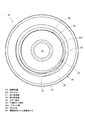
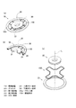
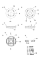
図1は本実施例の緩衝装置10の底面側からの斜視図であり、図2は緩衝装置10の説明図を示し、図3は緩衝装置10の底面図を示している。なお、図2(a)は緩衝装置10の正面図を示し、図2(b)は緩衝装置10の断面図を示している。
An embodiment of the present invention will be described below with reference to the drawings.
FIG. 1 is a perspective view from the bottom side of the shock absorber 10 according to the present embodiment, FIG. 2 is an explanatory view of the shock absorber 10, and FIG. 3 is a bottom view of the shock absorber 10. 2A shows a front view of the shock absorber 10, and FIG. 2B shows a cross-sectional view of the shock absorber 10.

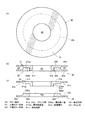
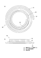
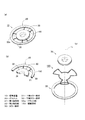
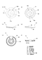
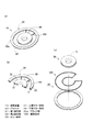
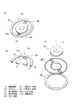
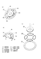
また、図4,図5はカラー部材30の説明図を示し、図6,図7は螺旋多段コイル渦巻きバネ50の説明図を示し、図8はグロメット20の説明図を示している。
なお、図4(a)は緩衝装置10のカラー部材30の平面図を示し、図4(b)はカラー部材30の断面図を示し、図4(c)はカラー部材30の分解断面図を示している。図5(a)は底面側から見たカラー部材30の分解斜視図を示し、図5(b)は上面側から見たカラー部材30の分解斜視図を示し、図5(c)は上面側から見たカラー部材30の斜視図を示している。
4 and 5 are explanatory diagrams of the collar member 30, FIGS. 6 and 7 are explanatory diagrams of the spiral multi-stage coil spiral spring 50, and FIG. 8 is an explanatory diagram of the grommet 20.
4A is a plan view of the collar member 30 of the shock absorber 10, FIG. 4B is a sectional view of the collar member 30, and FIG. 4C is an exploded sectional view of the collar member 30. Show. 5A is an exploded perspective view of the collar member 30 viewed from the bottom surface side, FIG. 5B is an exploded perspective view of the collar member 30 viewed from the top surface side, and FIG. The perspective view of the collar member 30 seen from FIG.

また、図6(a)は緩衝装置10の螺旋多段コイル渦巻きバネ50の底面図を示し、図6(b)は螺旋多段コイル渦巻きバネ50の正面図を示し、図7(a)は螺旋多段コイル渦巻きバネ50の底面側からの斜視図を示し、図7(b)は正面側が透過状態である螺旋多段コイル渦巻きバネ50の底面側からの斜視図を示している。さらに、図8(a)はグロメット20の平面図を示し、図8(b)はグロメット20の断面図を示し、図8(c)はグロメット20の底面図を示している。   6A shows a bottom view of the spiral multi-stage coil spiral spring 50 of the shock absorber 10, FIG. 6B shows a front view of the spiral multi-stage coil spiral spring 50, and FIG. 7A shows a spiral multi-stage coil spring 50. A perspective view from the bottom side of the coil spiral spring 50 is shown, and FIG. 7B shows a perspective view from the bottom side of the spiral multi-stage coil spiral spring 50 whose front side is in a transparent state. 8A is a plan view of the grommet 20, FIG. 8B is a cross-sectional view of the grommet 20, and FIG. 8C is a bottom view of the grommet 20.

また、図9は緩衝装置10の装着状態についての断面図を示し、図10はヒートインシュレータ3を構成するコルゲートシート120についての説明図を示し、図11は緩衝装置10の装着状態についての概略正面図を示している。   9 shows a cross-sectional view of the shock absorber 10 in a mounted state, FIG. 10 shows an explanatory view of the corrugated sheet 120 constituting the heat insulator 3, and FIG. 11 shows a schematic front view of the shock absorber 10 in a mounted state. The figure is shown.

なお、図10(a)はコルゲートシート120の斜視図を示し、図10(b)は図10(a)におけるI−I端面図を示し、図10(c)は図10(a)におけるII−II端面図を示し、図10(d)は図10(a)におけるIII−III端面図を示している。   10 (a) shows a perspective view of the corrugated sheet 120, FIG. 10 (b) shows an II end view in FIG. 10 (a), and FIG. 10 (c) shows II in FIG. 10 (a). -II end view is shown, and FIG. 10 (d) shows a III-III end view in FIG. 10 (a).

自動車などの車両のエンジン2の側面には、図11に示すように、燃焼排気ガスを排出するためのエキマニ1が取付けられている。そして、このエキマニ1に対して、エキマニ1を覆う態様のヒートインシュレータ3が取付けられている。   As shown in FIG. 11, an exhaust manifold 1 for discharging combustion exhaust gas is attached to a side surface of an engine 2 of a vehicle such as an automobile. And the heat insulator 3 of the aspect which covers the exhaust manifold 1 is attached with respect to this exhaust manifold 1. As shown in FIG.

本発明の緩衝装置10は、ヒートインシュレータ3をエキマニ1に取付けるためのフローティングマウント構造の緩衝装置であり、振動を緩衝する螺旋多段コイル渦巻きバネ50、グロメット20及びカラー部材30で構成している。   The shock absorber 10 according to the present invention is a shock absorber having a floating mount structure for attaching the heat insulator 3 to the exhaust manifold 1, and includes a spiral multistage coil spiral spring 50, a grommet 20, and a collar member 30 that buffer vibration.

カラー部材30は、径に対して高さの低い円柱状であり、SPCCなどの鉄系材料で構成される。また、カラー部材30は、図4(a)に示すように、平面視中央に取付ボルト42の挿通を許容するボルト孔40を備え、側面には、後述する螺旋多段コイル渦巻きバネ50のカラー部材装着部53の嵌着を許容する嵌合凹部33を備えている。   The collar member 30 has a columnar shape with a low height relative to the diameter, and is made of an iron-based material such as SPCC. Further, as shown in FIG. 4A, the collar member 30 includes a bolt hole 40 that allows insertion of the mounting bolt 42 in the center in plan view, and a collar member of a spiral multi-stage coil spiral spring 50 described later on the side surface. A fitting recess 33 that allows fitting of the mounting portion 53 is provided.

カラー部材30は、下向きに凸な上側カラー部材31と、下側カラー部材32と嵌着し、かしめて構成している。
詳しくは、上側カラー部材31は、径外側に配置したフランジ部31aと、該フランジ部31aの径内側に配置した円環状の厚肉部31bと、厚肉部31bの内周縁から上向きに突出する円筒状の嵌合筒部31cとを一体に構成している。なお、厚肉部31bの底面を31baとしている。
The collar member 30 is configured by being fitted with an upper collar member 31 projecting downward and a lower collar member 32 and caulking.
Specifically, the upper collar member 31 protrudes upward from the flange portion 31a disposed on the radially outer side, the annular thick portion 31b disposed on the radially inner side of the flange portion 31a, and the inner peripheral edge of the thick portion 31b. A cylindrical fitting tube portion 31c is integrally formed. The bottom surface of the thick portion 31b is 31ba.

下側カラー部材32は、底面におけるフランジ部31aに対応する径外側に配置したフランジ部32aと、内周部に上述の嵌合筒部31cの嵌着を許容する嵌着開口32cを備えた環状の厚肉部32bとで構成している。なお、厚肉部32bの上面を32baとしている。また、フランジ部31a,32aは、厚肉部31b,32bに比べて、後述する螺旋多段コイル渦巻きバネ50の断面半径分ほど薄く形成している。   The lower collar member 32 has an annular shape provided with a flange portion 32a disposed on the outer side corresponding to the flange portion 31a on the bottom surface, and a fitting opening 32c that allows fitting of the fitting tube portion 31c described above on the inner peripheral portion. The thick part 32b. In addition, the upper surface of the thick part 32b is set to 32ba. Further, the flange portions 31a and 32a are formed so as to be thinner than the thick portions 31b and 32b by the cross-sectional radius of a spiral multi-stage coil spiral spring 50 described later.

このように構成した上側カラー部材31の厚肉部31bの厚肉部底面31baと、下側カラー部材32の厚肉部32bの厚肉部上面32baとを対面させ、嵌着開口32cに挿入した嵌合筒部31cを径外側向きにかしめることにより、上側カラー部材31と下側カラー部材32とを一体化している。そして、このとき、上側カラー部材31のフランジ部31aと、下側カラー部材32のフランジ部32aとによって、平面視円周状で、円柱状のカラー部材30の側面から径内側向きに凹状の嵌合凹部33を構成している。   The thick part bottom surface 31ba of the thick part 31b of the upper collar member 31 thus configured and the thick part upper surface 32ba of the thick part 32b of the lower collar member 32 face each other and inserted into the fitting opening 32c. The upper collar member 31 and the lower collar member 32 are integrated by caulking the fitting cylinder portion 31c toward the radially outer side. At this time, the flange portion 31a of the upper collar member 31 and the flange portion 32a of the lower collar member 32 have a circumferential shape in a plan view and a concave fitting from the side surface of the columnar collar member 30 toward the radially inner side. A joint recess 33 is formed.

なお、上側カラー部材31の厚肉部31bの厚肉部底面31baと、下側カラー部材32の厚肉部32bの厚肉部上面32baとは、図9に示すように、平面視において取付ボルト42のボルトヘッド42aの外径より大きく形成している。
また、厚肉部底面31baと厚肉部上面32baとは、取付ボルト42の挿通方向に対して直交し、挿通方向において対面している。
The thick portion bottom surface 31ba of the thick portion 31b of the upper collar member 31 and the thick portion upper surface 32ba of the thick portion 32b of the lower collar member 32 are, as shown in FIG. It is formed larger than the outer diameter of the bolt head 42a.
Further, the thick portion bottom surface 31ba and the thick portion upper surface 32ba are orthogonal to the insertion direction of the mounting bolt 42 and face each other in the insertion direction.

また、嵌合凹部33は、螺旋多段コイル渦巻きバネ50の断面半径分ほど薄く形成したフランジ部31a,32aを対面させて構成しているため、螺旋多段コイル渦巻きバネ50の断面直径よりわずかに高さの高い平面視円周状の凹部を構成している。   Further, since the fitting recess 33 is formed by facing the flange portions 31 a and 32 a formed so as to be thinner than the cross-sectional radius of the spiral multi-stage coil spiral spring 50, the fitting recess 33 is slightly higher than the cross-sectional diameter of the spiral multi-stage coil spiral spring 50. A concave portion having a circular shape in a plan view is formed.

螺旋多段コイル渦巻きバネ50は、円形断面線材を巻き回して形成しており、径外側の螺旋渦巻き部51と、径内側の多段コイル部52とで構成している。
詳しくは、径外側から内側に向かうとともに、徐々に高さ方向に変化する螺旋渦巻き部51と、螺旋渦巻き部51の径内側端部から連続し、円筒状に巻き回した多段コイル部52とで構成している。このように構成することによって、螺旋渦巻き部51と多段コイル部52とは同じ円形断面線材を巻き回して構成しているものの、ピッチが異なるため螺旋渦巻き部51と多段コイル部52とでバネ定数が異なる。つまり、螺旋渦巻き状と円筒状とのように巻き回し方を変えることによって、一本の連続する円形断面線材を巻き回して形成する螺旋多段コイル渦巻きバネ50は、二種類の見かけのバネ定数を有することとなる。なお、カラー部材装着部53を多段コイル部52の端部に形成し、後述するグロメット20の連結部23に保持される被保持部54を、螺旋渦巻き部51の径方向外側部に備えている。
The spiral multi-stage coil spiral spring 50 is formed by winding a circular cross-section wire, and includes a spiral spiral portion 51 on the outer diameter side and a multi-stage coil portion 52 on the inner diameter side.
Specifically, the spiral spiral part 51 gradually changes in the height direction from the radially outer side to the inner side, and the multistage coil part 52 that is continuous from the radially inner end of the spiral spiral part 51 and wound in a cylindrical shape. It is composed. With this configuration, although the spiral spiral part 51 and the multistage coil part 52 are configured by winding the same circular cross-section wire, the spring constant is different between the spiral spiral part 51 and the multistage coil part 52 because the pitch is different. Is different. In other words, the spiral multi-stage coil spiral spring 50 formed by winding one continuous circular cross-section wire by changing the winding method like a spiral spiral and a cylindrical shape has two kinds of apparent spring constants. Will have. A collar member mounting portion 53 is formed at the end of the multi-stage coil portion 52, and a held portion 54 held by the connecting portion 23 of the grommet 20 described later is provided on the radially outer portion of the spiral spiral portion 51. .

螺旋多段コイル渦巻きバネ50の螺旋渦巻き部51について詳述すると、螺旋渦巻き部51は、渦巻き方向に沿って高さ方向(図6(b)における上下方向)に徐々に変化し、三巻きの螺旋渦巻き状に形成している。
また、螺旋多段コイル渦巻きバネ50は、上述したように、螺旋渦巻き状の径方向外側部に円弧状の被保持部54を備え、螺旋渦巻き状の径方向中心部の端部から連続して多段コイル部52を形成している。
The spiral spiral portion 51 of the spiral multi-stage coil spiral spring 50 will be described in detail. The spiral spiral portion 51 gradually changes in the height direction (vertical direction in FIG. 6B) along the spiral direction, so that three spirals are formed. It is formed in a spiral shape.
Further, as described above, the spiral multi-stage coil spiral spring 50 includes the arc-shaped held portion 54 on the radially outer portion of the spiral spiral, and is continuously multi-staged from the end of the spiral spiral radial center. A coil portion 52 is formed.

多段コイル部52は、上述したように、螺旋渦巻き部51の径内側の端部から連続し、高さ方向において狭ピッチ且つ同じ巻き径で巻き回して構成している。そして、その端部を、嵌合凹部33に装着するカラー部材装着部53としている。   As described above, the multi-stage coil unit 52 is continuous from the end portion on the inner diameter side of the spiral spiral unit 51 and is wound with a narrow pitch and the same winding diameter in the height direction. The end portion is a collar member mounting portion 53 that is mounted in the fitting recess 33.

カラー部材装着部53及び被保持部54は、端部から3/4円である270度の中心角度で、曲率が変化しない円弧形状で形成している(図6(a)参照)。なお、カラー部材装着部53の内周円は、上述のカラー部材30における嵌合凹部33の内側円33cよりわずかに大きな径で形成している。具体的には、約0.2mm大きな径で形成している。したがって、カラー部材装着部53の内周と、嵌合凹部33の内側円33cとの間に制振性向上のための隙間sが形成される(図2(b)a部拡大図参照)。   The collar member mounting portion 53 and the held portion 54 are formed in an arc shape having a central angle of 270 degrees, which is 3/4 circle from the end portion, and the curvature does not change (see FIG. 6A). The inner circumferential circle of the collar member mounting portion 53 is formed with a diameter slightly larger than the inner circle 33c of the fitting recess 33 in the collar member 30 described above. Specifically, it is formed with a diameter about 0.2 mm larger. Therefore, a gap s for improving vibration damping is formed between the inner periphery of the collar member mounting portion 53 and the inner circle 33c of the fitting recess 33 (see FIG. 2 (b) enlarged view of portion a).

なお、螺旋多段コイル渦巻きバネ50は、SUS304などのステンレスバネ鋼からなる線材で構成している。
また、螺旋多段コイル渦巻きバネ50を、螺旋渦巻き部51と多段コイル部52とで構成したが、抑制すべき振動の周波数帯域や振幅、使用状態温度などの各種使用条件にしたがって、長円形でも略矩形でも、その他の随意の閉曲面形状の断面線材で構成してもよく、線材の径や材料あるいは巻き数とともに、適宜選定すればよい。
The spiral multistage coil spiral spring 50 is made of a wire made of stainless spring steel such as SUS304.
Further, although the spiral multi-stage coil spiral spring 50 is configured by the spiral spiral section 51 and the multi-stage coil section 52, an oval shape may be substantially used according to various use conditions such as a frequency band and amplitude of vibration to be suppressed, and a use state temperature. The wire may be rectangular or may be composed of other optional cross-section wire having a closed curved surface, and may be appropriately selected along with the diameter, material, or number of turns of the wire.

グロメット20は、ヒートインシュレータ3を保持する第一保持部21と、螺旋多段コイル渦巻きバネ50を保持する第二保持部22と、第一保持部21と第二保持部22とを連結する連結部23とで、平面視中央に挿通穴24を有し、片断面略S字形状となる円環状に構成している。   The grommet 20 includes a first holding part 21 that holds the heat insulator 3, a second holding part 22 that holds the spiral multistage coil spiral spring 50, and a connecting part that connects the first holding part 21 and the second holding part 22. 23, and has an insertion hole 24 in the center in plan view, and is formed in an annular shape having a substantially S-shaped section.

詳しくは、ヒートインシュレータ3を径外側で保持する第一保持部21は、円環状の金属板の外周縁から内周側における所定の半径方向長さ部分を、図8の上方から下方に向かい、径方向内周側から外周側に折り返して径外向き倒位のJ字形状に形成している。なお、第一保持部21は、後述するヒートインシュレータ3を挟み込む厚みで形成している。   Specifically, the first holding portion 21 that holds the heat insulator 3 on the radially outer side has a predetermined radial length portion on the inner peripheral side from the outer peripheral edge of the annular metal plate, and extends downward from the upper side in FIG. Folded from the radially inner periphery side to the outer periphery side, it is formed in a J-shape that is inverted radially outward. In addition, the 1st holding | maintenance part 21 is formed with the thickness which pinches | interposes the heat insulator 3 mentioned later.

また、螺旋多段コイル渦巻きバネ50を径内側で保持する第二保持部22は、環状の金属板の内周縁から外周側における所定の半径方向長さ部分を、図8の下方から上方に向かい、径方向外周側から内周側に折り返して径内向き倒位のJ字形状に形成している。   Further, the second holding portion 22 that holds the spiral multi-stage coil spiral spring 50 on the inner diameter side has a predetermined radial length portion from the inner peripheral edge to the outer peripheral side of the annular metal plate from the lower side to the upper side in FIG. Folded from the radially outer periphery side to the inner periphery side, it is formed in a J-shape that is inverted radially inward.

なお、第二保持部22は、上述の螺旋多段コイル渦巻きバネ50を挟み込む厚みで形成されている。さらに、螺旋多段コイル渦巻きバネ50の被保持部54の外周円と、倒位のJ字形状の第二保持部22の内側との間にわずかな隙間sを形成している(図2(b)b部拡大図参照)。   In addition, the 2nd holding | maintenance part 22 is formed in the thickness which pinches | interposes the above-mentioned spiral multistage coil spiral spring 50. FIG. Furthermore, a slight gap s is formed between the outer circumference of the held portion 54 of the spiral multi-stage coil spiral spring 50 and the inside of the inverted J-shaped second holding portion 22 (FIG. 2B). ) Refer to the enlarged view of part b).

連結部23は、第一保持部21と第二保持部22とに亘って屈曲して形成され、径外向き倒位のJ字形状に形成した第一保持部21の径内側の下側端部と、径内向き倒位のJ字形状に形成した第二保持部22の径外側の上側端部とを相互に連結する構成である。これら第二保持部22、連結部23及び第一保持部21は、エキマニ1に設けたボルト用ボス41の側からこの順序で配置される。   The connecting portion 23 is formed by bending over the first holding portion 21 and the second holding portion 22, and has a lower end on the inner side of the first holding portion 21 that is formed in a J-shape that is inverted radially outward. And the upper end portion outside the diameter of the second holding portion 22 formed in a J-shape inverted inwardly in the diameter. The second holding part 22, the connecting part 23, and the first holding part 21 are arranged in this order from the side of the bolt boss 41 provided on the exhaust manifold 1.

上述したように緩衝装置10は、上述の構成のカラー部材30、螺旋多段コイル渦巻きバネ50、及びグロメット20を組み付けて構成している。詳述すると、カラー部材30の嵌合凹部33に、螺旋多段コイル渦巻きバネ50の多段コイル部52のカラー部材装着部53を嵌合させて、カラー部材30と螺旋多段コイル渦巻きバネ50とを組み付ける。このとき、上述したように、嵌合凹部33の内側円33cと螺旋多段コイル渦巻きバネ50のカラー部材装着部53の内周側との間に隙間sが設けられるとともに、カラー部材装着部53は、内側円33cの周面に対して3/4の範囲を巻き付けることができる。   As described above, the shock absorber 10 is configured by assembling the collar member 30, the spiral multistage coil spiral spring 50, and the grommet 20 having the above-described configuration. Specifically, the collar member 30 and the spiral multi-stage coil spiral spring 50 are assembled by fitting the collar member mounting portion 53 of the multi-stage coil portion 52 of the spiral multi-stage coil spiral spring 50 into the fitting recess 33 of the collar member 30. . At this time, as described above, a gap s is provided between the inner circle 33c of the fitting recess 33 and the inner peripheral side of the collar member mounting portion 53 of the spiral multistage coil spiral spring 50, and the color member mounting portion 53 is A range of 3/4 can be wound around the circumferential surface of the inner circle 33c.

また、グロメット20の第二保持部22に、螺旋多段コイル渦巻きバネ50の螺旋渦巻き部51の被保持部54を嵌合させて、グロメット20と螺旋多段コイル渦巻きバネ50とを組み付ける。このとき、上述したように、グロメット20の第二保持部22の内周面と、螺旋多段コイル渦巻きバネ50の被保持部54との外周の間に隙間sが設けられるとともに、被保持部54は、第二保持部22の内周面に対して3/4の範囲に配置される。   Further, the grommet 20 and the spiral multistage coil spiral spring 50 are assembled by fitting the held portion 54 of the spiral spiral section 51 of the spiral multistage coil spiral spring 50 to the second holding section 22 of the grommet 20. At this time, as described above, a gap s is provided between the inner peripheral surface of the second holding portion 22 of the grommet 20 and the outer periphery of the held portion 54 of the spiral multi-stage coil spiral spring 50, and the held portion 54. Is arranged in a range of 3/4 with respect to the inner peripheral surface of the second holding part 22.

また、図2(b)に示すように、径外側の被保持部54が径内側のカラー部材装着部53より高くなるように螺旋多段コイル渦巻きバネ50を緩衝装置10とカラー部材30との間に配置するため、嵌合凹部33でカラー部材装着部53を嵌合するカラー部材30は、被保持部54を保持する第二保持部22は、高い位置(図2(b)において上方向)となるように組み付けられる。   Further, as shown in FIG. 2B, the spiral multistage coil spiral spring 50 is placed between the shock absorber 10 and the collar member 30 so that the held portion 54 on the outer diameter side is higher than the collar member mounting portion 53 on the inner diameter side. Since the collar member 30 that fits the collar member mounting portion 53 in the fitting recess 33 is disposed at the second holding portion 22 that holds the held portion 54, the collar member 30 is at a high position (upward in FIG. 2B). It is assembled to become.

このように構成された緩衝装置10は、図9に示すように、ヒートインシュレータ3に形成された装着孔3aに装着され、エキマニ1に形成されたボルト用ボス41に螺挿される取付ボルト42によって、ボルト用ボス41に固定される。   As shown in FIG. 9, the shock absorber 10 configured in this way is attached to a mounting hole 3 a formed in the heat insulator 3, and is attached by a mounting bolt 42 screwed into a bolt boss 41 formed in the exhaust manifold 1. The bolt boss 41 is fixed.

ヒートインシュレータ3は、図11に示すように、エンジン2の側面に取付けられたエキマニ1を覆うように形成されており、エキマニ1に設けられた複数のボルト用ボス41に対して、緩衝装置10を介して、取付ボルト42によって固定される。   As shown in FIG. 11, the heat insulator 3 is formed so as to cover the exhaust manifold 1 attached to the side surface of the engine 2, and the shock absorber 10 against the plurality of bolt bosses 41 provided on the exhaust manifold 1. It is fixed by the mounting bolt 42 via

コルゲートシート120は、図10(b),(c)に示すように、隆起部121と谷部122とが交互に連続してX方向に連なるとともに、Y方向において、各隆起部121と谷部122との高さがそれぞれ、図10(d)に示すように、一定間隔で頂部(121a,122a)と底部(121b,122b)とを繰り返して形成されたコルゲート形状のアルミ板である。   As shown in FIGS. 10B and 10C, the corrugated sheet 120 has ridges 121 and valleys 122 alternately and continuously extending in the X direction, and each ridge 121 and valley in the Y direction. As shown in FIG. 10 (d), each of the heights 122 is a corrugated aluminum plate formed by repeating the top (121a, 122a) and the bottom (121b, 122b) at regular intervals.

なお、隆起部121と谷部122とは、X方向において、等間隔で幅広と幅狭とを一定間隔毎に交互に繰り返して上記コルゲート形状を形成している。
詳しくは、コルゲートシート120のコルゲート形状は、それぞれがY方向に沿って延びる隆起部121と谷部122とがX方向に交互に繰り返されている。
The raised portion 121 and the valley portion 122 form the corrugated shape by alternately repeating wide and narrow at regular intervals at regular intervals in the X direction.
Specifically, in the corrugated shape of the corrugated sheet 120, the ridges 121 and the valleys 122 each extending along the Y direction are alternately repeated in the X direction.

隆起部121は、Y方向に沿って、頂部121aと底部121bとが谷部122から立上って交互に配列され、谷部122は、Y方向に沿って、頂部である平坦部122aと底部である凹部122bとが交互に配列されている。   The ridges 121 are alternately arranged with the tops 121a and the bottoms 121b rising from the valleys 122 along the Y direction, and the valleys 122 are the tops of the flats 122a and the bottoms along the Y direction. The recesses 122b are alternately arranged.

頂部121aは、谷部122から略逆台形状に立上がる一対の側壁と、側壁の先端が相互に連結されて形成される比較的平坦な頂部とで構成するとともに、頂部121aは内曲しており、頂部121aの基端部よりも先端部のほうが幅広になる。   The top part 121a is composed of a pair of side walls that rise in a substantially inverted trapezoidal shape from the valley part 122, and a relatively flat top part that is formed by connecting the tips of the side walls to each other. The tip end portion is wider than the base end portion of the top 121a.

底部121bは、平坦部122aからそれぞれ立上がる一対の側壁と、側壁の先端を相互に連結した凹状の凹部122bとで構成され、頂部121a及び凹部122b、並びに底部121b及び平坦部122aが、X方向に沿ってそれぞれ断続的に連なるように形成している。   The bottom part 121b is composed of a pair of side walls rising from the flat part 122a, and a concave concave part 122b in which the tips of the side walls are connected to each other. The top part 121a and the concave part 122b, and the bottom part 121b and the flat part 122a Are formed so as to be intermittently connected to each other.

そして、このコルゲートシート120を所定形状に形状加工したヒートインシュレータ3において、エキマニ1に設けたボルト用ボス41に対応する箇所に装着孔3aを形成するとともに、装着孔3aの周辺のコルゲート形状を潰して略平板形状に形成する押し潰し部3bを、グロメット20の第一保持部21で保持している。   In the heat insulator 3 in which the corrugated sheet 120 is processed into a predetermined shape, the mounting hole 3a is formed at a location corresponding to the bolt boss 41 provided in the exhaust manifold 1, and the corrugated shape around the mounting hole 3a is crushed. The crushing portion 3b formed in a substantially flat plate shape is held by the first holding portion 21 of the grommet 20.

また、立体形状に形成されたヒートインシュレータ3は、上記コルゲート形状において相互に交差するいずれか一方の方向が立体形状を構成する主要な稜線相当部位に対して交差する方向に定められている。   Further, the heat insulator 3 formed in a three-dimensional shape is defined in a direction in which any one of the corrugated shapes intersecting with each other intersects with a main ridge line corresponding portion constituting the three-dimensional shape.

より詳述すると、ヒートインシュレータ3は上述したようにエキマニ1の立体的な外観形状に沿った立体形状に形成されるので、ヒートインシュレータ3には屈曲部位であるひとつ、あるいは複数の稜線相当部位が形成される。本実施例では、コルゲート形状の長手方向が、これら複数の稜線相当部位のうちの主要な稜線相当部位に交差する方向となるように、立体形状へのプレス加工を施している。   More specifically, since the heat insulator 3 is formed into a three-dimensional shape that conforms to the three-dimensional appearance of the exhaust manifold 1 as described above, the heat insulator 3 has one or more ridge line corresponding portions that are bent portions. It is formed. In the present embodiment, the corrugated shape is pressed into a three-dimensional shape so that the longitudinal direction of the corrugated shape intersects the main ridge line equivalent portion of the plurality of ridge line equivalent portions.

ここで、主要な稜線相当部位とは、ヒートインシュレータ3の全体的な形状を特徴付ける比較的大きな曲率を有する折り曲げ部位が連続する部位である。即ち、ヒートインシュレータ3に形成される大小種々の折り曲げ部位のうち、ヒートインシュレータ3の外観形状を実質的に決定付ける比較的長寸に亘って延びる折り曲げ部位である。   Here, the main ridge line equivalent part is a part where a bent part having a relatively large curvature characterizing the overall shape of the heat insulator 3 continues. That is, among the various bent portions formed on the heat insulator 3, the bent portion extends over a relatively long length that substantially determines the external shape of the heat insulator 3.

ヒートインシュレータ3がエキマニ1に対して装着されると、エキマニ1からの振動の伝達によりヒートインシュレータ3も振動する。この振動によりヒートインシュレータ3が振動すると、主要な稜線相当部位を中心にしてその両側のヒートインシュレータ3の部位が蝶の羽根のように大きく振動する。このような振動が発生すると、ヒートインシュレータ3の稜線相当部位付近の部位が繰り返しの屈曲により金属疲労を生じクラックを発生しやすくなる。   When the heat insulator 3 is attached to the exhaust manifold 1, the heat insulator 3 also vibrates due to the transmission of vibration from the exhaust manifold 1. When the heat insulator 3 vibrates due to this vibration, the portions of the heat insulator 3 on both sides of the portion corresponding to the main ridge line are vibrated greatly like butterfly wings. When such vibration is generated, a portion near the ridge line portion of the heat insulator 3 is subject to metal fatigue due to repeated bending, and cracks are likely to occur.

これに対して、本実施例のヒートインシュレータ3は、ヒートインシュレータ3に形成されているコルゲート形状の一方向が、主要な稜線相当部位に対して交差する方向、好適には直交する方向となるように定められているので、コルゲート形状が稜線相当部位を中心とする振動に対してリブの作用を実現する。これにより、ヒートインシュレータ3の振動を抑制することができ、ヒートインシュレータ3のクラックの発生を防止することができ、ヒートインシュレータ3の品質を格段に向上することができる。   On the other hand, the heat insulator 3 according to the present embodiment is such that one direction of the corrugated shape formed in the heat insulator 3 intersects the main ridge line corresponding portion, and is preferably orthogonal. Therefore, the corrugated shape realizes the action of the rib against the vibration centered on the ridge line corresponding portion. Thereby, the vibration of the heat insulator 3 can be suppressed, the occurrence of cracks in the heat insulator 3 can be prevented, and the quality of the heat insulator 3 can be significantly improved.

このように構成することによって、ヒートインシュレータ3は、図9に示すように、ヒートインシュレータ3に形成された装着孔3aに装着された緩衝装置10を介して、エキマニ1に設けられたボルト用ボス41に対して固定することができる。   By configuring in this way, the heat insulator 3 is, as shown in FIG. 9, the bolt boss provided in the exhaust manifold 1 via the shock absorber 10 mounted in the mounting hole 3 a formed in the heat insulator 3. 41 can be fixed.

上述したように、緩衝装置10は、振動源であるエキマニ1に設けたボルト用ボス41と接続対象であるヒートインシュレータ3との間に配置し、エキマニ1に設けたボルト用ボス41とヒートインシュレータ3とを連結するとともに、エキマニ1に設けたボルト用ボス41からヒートインシュレータ3への振動の伝達を緩衝する装置であり、上記構成により、上述したように、緩衝装置10は安定して優れた制振性を奏することができる。   As described above, the shock absorber 10 is disposed between the bolt boss 41 provided on the exhaust manifold 1 that is the vibration source and the heat insulator 3 that is the connection target, and the bolt boss 41 provided on the exhaust manifold 1 and the heat insulator. 3 and a device for buffering vibration transmission from the bolt boss 41 provided on the exhaust manifold 1 to the heat insulator 3. As described above, the shock absorber 10 is stable and excellent. It can exhibit vibration damping.

詳しくは、カラー部材30を、径方向に適宜の厚みを有する厚肉部31b,32bと、リング部の上下端の一方から径外側向きに突出する円盤状のフランジ部31a,32aとで片断面が略L字状に構成された上側カラー部材31,下側カラー部材32を、フランジ部31a,32aが外側となるように、厚肉部31bの厚肉部底面31baと、厚肉部32bの厚肉部上面32baとを、取付ボルト42の挿通方向において対面させて組み付けて構成することにより、制振性の高い緩衝装置10の製品信頼性を向上することができる。   Specifically, the collar member 30 has a single cross section with thick portions 31b and 32b having an appropriate thickness in the radial direction and disk-shaped flange portions 31a and 32a protruding outward from the upper and lower ends of the ring portion. The upper collar member 31 and the lower collar member 32, each of which is configured in a substantially L shape, are formed so that the flange portions 31a and 32a are on the outer side, the thick portion bottom surface 31ba of the thick portion 31b, and the thick portion 32b. The product reliability of the shock absorber 10 with high vibration damping can be improved by configuring the thick portion upper surface 32ba so as to face each other in the insertion direction of the mounting bolt 42.

詳しくは、カラー部材30を、径方向に適宜の厚みを有する厚肉部31b,32bと、リング部の上下端の一方から径外側向きに突出する円盤状のフランジ部31a,32aとで片断面が略L字状に構成した上側カラー部材31及び下側カラー部材32を、フランジ部31a,32aが外側となるように、厚肉部31bの厚肉部底面31baと、厚肉部32bの厚肉部上面32baとを対面させて組み付けて構成することによって、対面する厚肉部31b,32bと、両フランジ部31a,32aとで囲まれる空間で嵌合凹部33を構成することができる。   Specifically, the collar member 30 has a single cross section with thick portions 31b and 32b having an appropriate thickness in the radial direction and disk-shaped flange portions 31a and 32a protruding outward from the upper and lower ends of the ring portion. The upper collar member 31 and the lower collar member 32, each of which is configured in a substantially L shape, have a thick portion bottom surface 31ba of the thick portion 31b and a thickness of the thick portion 32b so that the flange portions 31a and 32a are on the outside. The fitting recess 33 can be formed in a space surrounded by the thick portions 31b and 32b facing each other and the flange portions 31a and 32a by assembling the meat portion upper surface 32ba so as to face each other.

また、組み付け状態の上側カラー部材31,下側カラー部材32の厚肉部31bの厚肉部底面31baと、厚肉部32bの厚肉部上面32baとを対面させているため、組み付けられたカラー部材30のボルト孔40に取付ボルト42を挿通してエキマニ1に固定する際に、両フランジ部31a,32aが取付ボルト42の締結圧力によって、変形することを防止できる。   Further, since the thick portion bottom surface 31ba of the thick portion 31b of the assembled upper color member 31 and lower collar member 32 and the thick portion upper surface 32ba of the thick portion 32b face each other, the assembled color When the mounting bolt 42 is inserted into the bolt hole 40 of the member 30 and fixed to the exhaust manifold 1, it is possible to prevent the flange portions 31 a and 32 a from being deformed by the fastening pressure of the mounting bolt 42.

さらには、上側カラー部材31の厚肉部31bの厚肉部底面31baと、下側カラー部材32の厚肉部32bの厚肉部上面32baとは、図9に示すように、平面視において取付ボルト42のボルトヘッド42aの外径よりも小さな内径及び大きな外径を有するリング形状で形成しているため、取付ボルト42の締め付けによるボルトヘッド42aからの締結圧力によって、両フランジ部31a,32aが取付ボルト42の締結圧力によって、変形することを防止できる。   Furthermore, the thick portion bottom surface 31ba of the thick portion 31b of the upper collar member 31 and the thick portion upper surface 32ba of the thick portion 32b of the lower collar member 32 are attached in plan view as shown in FIG. Since the bolt 42 is formed in a ring shape having an inner diameter smaller than the outer diameter of the bolt head 42 a and a larger outer diameter, the flange portions 31 a and 32 a are caused by the fastening pressure from the bolt head 42 a by tightening the mounting bolt 42. The deformation can be prevented by the fastening pressure of the mounting bolt 42.

したがって、取付ボルト42の締結状態に関わらず、カラー部材装着部53と嵌合凹部33との間に形成された制振性向上のための隙間Sを確保することができ、カラー部材装着部53と嵌合凹部33において衝突音が生じることなく、カラー部材30を介して入力された振動を隙間Sで吸収することができる。また、隙間Sにより、熱の伝達を遮断することができる。   Therefore, regardless of the fastening state of the mounting bolt 42, a gap S for improving vibration damping formed between the collar member mounting portion 53 and the fitting recess 33 can be secured, and the collar member mounting portion 53 is secured. The vibration input through the collar member 30 can be absorbed by the gap S without causing a collision sound in the fitting recess 33. Further, heat transfer can be blocked by the gap S.

さらにまた、嵌合凹部33とカラー部材装着部53との間に制振性を向上するための隙間Sを設けているため、緩衝装置10における制振性をさらに向上することができる。詳しくは、円弧状に形成したカラー部材装着部53を嵌合凹部33で保持する状態において制振性を向上するための隙間Sを形成しているため、つまり、制振性向上のためにわずか0.2mm程度の隙間Sを形成しているため、従来技術の緩衝装置5のように、カラー部材10と緩衝部材8との間に形成し、それぞれが遊動するように積極的に形成した軸線方向及び半径方向(平面方向)の隙間17(図43参照)のように、カラー部材装着部53と嵌合凹部33において衝突音が生じることなく、カラー部材30を介して入力された振動を隙間Sで吸収することができる。また、隙間Sにより、熱の伝達を遮断することができる。   Furthermore, since the clearance S for improving the vibration damping property is provided between the fitting recess 33 and the collar member mounting portion 53, the vibration damping property of the shock absorber 10 can be further improved. Specifically, since the gap S for improving the vibration damping property is formed in the state in which the collar member mounting portion 53 formed in the arc shape is held by the fitting recess 33, that is, a slight amount for improving the vibration damping property. Since the gap S of about 0.2 mm is formed, the axis is formed between the collar member 10 and the buffer member 8 and actively formed so that each of them moves freely like the buffer device 5 of the prior art. As in the gap 17 (see FIG. 43) in the radial direction and the radial direction (planar direction), the vibration input through the collar member 30 is not generated in the collar member mounting portion 53 and the fitting recess 33 without causing a collision sound. S can be absorbed. Further, heat transfer can be blocked by the gap S.

また、カラー部材30は、上側カラー部材31及び下側カラー部材32の一部分である厚肉部底面31baと厚肉部上面32baとを対面させて組付けることにより間隔保持手段を構成し、取付ボルト42の挿通方向における両側から挟み込むフランジ部31a,32aと、カラー部材装着部53との相対関係を確実に保持しているため、別の構成部品で間隔保持手段を構成する場合と比べて、部品点数を低減することができ、組み立て工程やコストを低減することができる。   In addition, the collar member 30 constitutes a spacing holding means by assembling the thick portion bottom surface 31ba and the thick portion top surface 32ba facing each other as a part of the upper collar member 31 and the lower collar member 32, and mounting bolts. Since the relative relationship between the flange portions 31a and 32a sandwiched from both sides in the insertion direction of the 42 and the collar member mounting portion 53 is securely held, the component is compared with the case where the interval holding means is configured by another component. The number of points can be reduced, and the assembly process and cost can be reduced.

さらに、別の構成部品で間隔保持手段を構成する場合、例えば間隔保持手段が脱落して間隔保持できなくなるおそれがあるが、間隔保持手段として、カラー部材30は、上側カラー部材31及び下側カラー部材32の一部分である厚肉部底面31baと厚肉部上面32baとを対面させて組付けているため、カラー部材30から脱落することがなく、確実にフランジ部31a,32aの間隔を保持することができる。   Further, in the case where the interval holding means is constituted by another component, for example, there is a possibility that the interval holding means may fall off and the interval cannot be held. As the interval holding means, the collar member 30 is composed of the upper collar member 31 and the lower collar. Since the thick portion bottom surface 31ba and the thick portion top surface 32ba, which are a part of the member 32, are assembled so as to face each other, they do not fall off the collar member 30, and the interval between the flange portions 31a, 32a is reliably maintained. be able to.

また、厚肉部底面31ba及び厚肉部上面32baを、ボルト孔40を構成する厚肉部31b,32bの一部として構成しているため、カラー部材30の形状をシンプルに構成することができる。したがって、上側カラー部材31や下側カラー部材32の加工成形性を向上することができる。   Moreover, since the thick part bottom surface 31ba and the thick part upper surface 32ba are configured as a part of the thick parts 31b, 32b constituting the bolt hole 40, the shape of the collar member 30 can be configured simply. . Therefore, the processability of the upper collar member 31 and the lower collar member 32 can be improved.

さらには、上側カラー部材31の嵌合筒部31cを下側カラー部材32の嵌着開口32cに挿入するとともにかしめて一体化しているため、カラー部材30に対して、フランジ部31a,32aが離れる方向の外力が作用した場合であっても、フランジ部31a,32a同士が離れることはない。したがって、フランジ部31a,32aとカラー部材装着部53との所望の相対関係を確実に保持することができる。つまり、上側カラー部材31の嵌合筒部31cと下側カラー部材32の嵌着開口32cとのカシメ固定は、フランジ部31a,32a同士の間隔が離れる方向の外力に対して間隔を保持する間隔保持手段としても機能することができる。   Further, since the fitting cylinder portion 31 c of the upper collar member 31 is inserted into the fitting opening 32 c of the lower collar member 32 and is integrated by caulking, the flange portions 31 a and 32 a are separated from the collar member 30. Even when a direction external force is applied, the flange portions 31a and 32a are not separated from each other. Therefore, the desired relative relationship between the flange portions 31a and 32a and the collar member mounting portion 53 can be reliably maintained. In other words, the caulking and fixing between the fitting cylinder portion 31c of the upper collar member 31 and the fitting opening 32c of the lower collar member 32 is an interval that keeps the interval against the external force in the direction in which the interval between the flange portions 31a and 32a is separated. It can also function as a holding means.

また、緩衝部材を、平面視渦巻き状の線材で構成する螺旋多段コイル渦巻きバネ50とし、カラー部材30の装着を許容するカラー部材装着部53を、平面視渦巻き状における径方向中心部に備えるとともに、カラー部材装着部53を保持する嵌合凹部33をカラー部材30の径外側に備えたため、カラー部材30から螺旋多段コイル渦巻きバネ50に伝達された振動により、平面視渦巻き状の線材で構成した螺旋多段コイル渦巻きバネ50自身が撓み運動を行う。この撓み運動により、緩衝装置10は、カラー部材30から伝達された振動の振動エネルギーを螺旋多段コイル渦巻きバネ50の撓みの運動エネルギーに変換し、ヒートインシュレータ3に伝達する振動を抑制することができる。   In addition, the shock absorbing member is a spiral multi-stage coil spiral spring 50 formed of a spiral wire in plan view, and a collar member mounting portion 53 that allows the collar member 30 to be mounted is provided in the central portion in the radial direction in the spiral shape in plan view. Since the fitting recess 33 for holding the collar member mounting portion 53 is provided outside the diameter of the collar member 30, it is configured by a spiral wire in plan view by vibration transmitted from the collar member 30 to the spiral multi-stage coil spiral spring 50. The spiral multistage coil spiral spring 50 itself bends. Due to this bending motion, the shock absorber 10 can convert the vibrational energy of vibration transmitted from the collar member 30 into the bending kinetic energy of the helical multi-stage coil spiral spring 50 and suppress the vibration transmitted to the heat insulator 3. .

つまり、従来技術の緩衝装置5において、カラー部材10と緩衝部材8との間に、それぞれが遊動するように積極的に形成した軸線方向、つまり挿通方向及び半径方向(平面方向)の隙間17の役目を螺旋多段コイル渦巻きバネ50における螺旋渦巻き部51の線材同士のクリアランスで実現し、入力振動の伝達を抑制する、つまり優れた制振性を実現している。   That is, in the shock absorber 5 of the prior art, the gap 17 in the axial direction, that is, the insertion direction and the radial direction (plane direction), which is positively formed so as to freely move between the collar member 10 and the shock absorbing member 8. The role is realized by the clearance between the wires of the spiral spiral portion 51 in the spiral multi-stage coil spiral spring 50, and the transmission of the input vibration is suppressed, that is, excellent damping performance is realized.

なお、本実施例の緩衝装置10は、自動車のエンジン2に装着されるエキマニ1用のヒートインシュレータ3に関連して説明されたが、本発明はこのような実施例に限定されるものではなく、例えば、車体の底部をカバーするアンダーカバー等の自動車の他の部位に装着される種々の用途のカバー類の取付に実施してもよい。また、自動車以外の種々の用途のカバー類の取付に実施できるものである。   The shock absorber 10 of the present embodiment has been described in relation to the heat insulator 3 for the exhaust manifold 1 mounted on the engine 2 of the automobile, but the present invention is not limited to such an embodiment. For example, the present invention may be applied to attachment of covers for various uses such as an under cover that covers the bottom of the vehicle body. Moreover, it can implement for attachment of covers of various uses other than a motor vehicle.

また、上述のカラー部材30では、上側カラー部材31の嵌合筒部31cを、下側カラー部材32の嵌着開口32cに挿入してカシメて一体化したが、図12に示すように、異なる方法で上側カラー部材31と下側カラー部材32とを固定してもよい。なお、別の形態のカラー部材30についての説明図である図12において、図12(a)は螺合によって固定するカラー部材30についての説明図であり、図12(b)は凹部への圧入によって固定するカラー部材30についての説明図を示している。   Further, in the above-described collar member 30, the fitting tube portion 31c of the upper collar member 31 is inserted into the fitting opening 32c of the lower collar member 32 and is integrated by crimping. However, as shown in FIG. The upper collar member 31 and the lower collar member 32 may be fixed by a method. In addition, in FIG. 12 which is explanatory drawing about the collar member 30 of another form, Fig.12 (a) is explanatory drawing about the collar member 30 fixed by screwing, FIG.12 (b) is press-fit in a recessed part. The explanatory view about the collar member 30 fixed by is shown.

詳しくは、螺合によって固定するカラー部材30は、図12(a−2),(a−3)に示すように、上側カラー部材31の嵌合筒部31cの外周面31caと、下側カラー部材32における嵌着開口32cの内周面32caとに形成したネジ溝を螺合し、図12(a−1)に示すように上側カラー部材31と下側カラー部材32とを固定する。   Specifically, as shown in FIGS. 12A-2 and 12A-3, the collar member 30 fixed by screwing includes an outer peripheral surface 31ca of the fitting cylinder portion 31c of the upper collar member 31, and a lower collar. The thread groove formed in the inner peripheral surface 32ca of the fitting opening 32c in the member 32 is screwed together, and the upper collar member 31 and the lower collar member 32 are fixed as shown in FIG.

なお、下側カラー部材32を、嵌着開口32cを有するフランジ部32aのみで構成するとともに、上側カラー部材31の厚肉部31bを嵌合凹部33に対応する高さで形成し、その端部から下方に突出するように、フランジ部32aに対応する高さの嵌合筒部31cを形成してもよい。   The lower collar member 32 is constituted only by the flange portion 32a having the fitting opening 32c, and the thick portion 31b of the upper collar member 31 is formed at a height corresponding to the fitting recess 33, and its end portion The fitting cylinder portion 31c having a height corresponding to the flange portion 32a may be formed so as to protrude downward from the flange portion 32a.

この場合も、嵌着開口32cの内面32caと、嵌合筒部31cの外周面31caとに形成したネジ溝を螺合して上側カラー部材31と下側カラー部材32とを固定することとなる。なお、この場合、厚肉部底面31baは、フランジ部32aの上面と対面して面接触する構成となる。   Also in this case, the upper collar member 31 and the lower collar member 32 are fixed by screwing the thread grooves formed on the inner surface 32ca of the fitting opening 32c and the outer peripheral surface 31ca of the fitting cylinder portion 31c. . In this case, the thick portion bottom surface 31ba is configured to face the upper surface of the flange portion 32a and come into surface contact therewith.

また、下側カラー部材32の厚肉部上面32baに形成した圧入凹部32bbへの圧入によって固定するカラー部材30は、図12(b−2),(b−3)に示すように、厚肉部底面31baと厚肉部上面32baとを対面させた状態で、厚肉部上面32baに形成した圧入凹部32bbに対応する位置の厚肉部31bをプレスして、圧入凹部32bbに上側カラー部材31の厚肉部31bの一部を圧入し、図12(b−1)に示すように上側カラー部材31と下側カラー部材32とを固定する。このように、カラー部材30における上側カラー部材31と下側カラー部材32との固定方法は、このほかスポット溶接等で固定する等、様々な方法があり、その方法を限定するものではない。   Further, the collar member 30 to be fixed by press-fitting into the press-fit recess 32bb formed on the thick-walled upper surface 32ba of the lower collar member 32 is thick as shown in FIGS. 12 (b-2) and 12 (b-3). With the bottom surface 31ba and the thick portion upper surface 32ba facing each other, the thick portion 31b at a position corresponding to the press-fit recess 32bb formed on the thick portion upper surface 32ba is pressed, and the upper collar member 31 is pressed into the press-fit recess 32bb. A part of the thick part 31b is press-fitted, and the upper collar member 31 and the lower collar member 32 are fixed as shown in FIG. As described above, there are various methods for fixing the upper collar member 31 and the lower collar member 32 in the collar member 30 such as spot welding or the like, and the method is not limited.

また、上述の説明では、緩衝部材として、螺旋渦巻き状の線材で構成する螺旋多段コイル渦巻きバネ50を用いたが、これに限定されず、図13乃至図42に示すように、様々な形状の緩衝部材を用いても、螺旋多段コイル渦巻きバネ50による効果以外の効果を得ることができるのは明らかである。   In the above description, the spiral multi-stage coil spiral spring 50 made of a spiral spiral wire is used as the buffer member. However, the present invention is not limited to this, and as shown in FIGS. It is obvious that effects other than the effects of the spiral multi-stage coil spiral spring 50 can be obtained even if the buffer member is used.

なお、以下の説明においては、緩衝部材の代替について説明するため、図13乃至図42において、緩衝装置10におけるグロメット20及びカラー部材30については上述の説明の緩衝装置10におけるグロメット20及びカラー部材30と同様の構成であるため点線で示し、この説明の本質部分である緩衝部材150についてのみ実線で表している。   In the following description, in order to describe an alternative of the buffer member, in FIGS. 13 to 42, the grommet 20 and the collar member 30 in the buffer device 10 are the same as those in the buffer device 10 described above. Since the configuration is the same as that shown in FIG. 1, it is indicated by a dotted line, and only the buffer member 150 which is an essential part of the description is indicated by a solid line.

第2の実施例の緩衝部材150は、対向する2方向に配置された略扇状部分と、扇状部分の間を連結する円弧状部分とを1本の鋼製線材で構成し、扇状部分の外周を第二保持部22で保持するとともに、円弧状部分をカラー部材30の嵌合凹部33で保持する構成である。なお、第2の実施例の緩衝部材150を備えた緩衝装置10についての説明図である図13、図14において、図13(a)は平面図、図13(b)は底面図、図13(c)は正面図、図13(d)は右側面図、図13(e)は平面方向断面図、図13(f)は図13(a)におけるA−A断面図を示している。また、図14(a)は底面側から見た拡大斜視図を示し、図14(b)は底面側から見た斜視片側拡大断面図を示し、図14(c)は鉛直方向の軸線Lに沿って、グロメット20とカラー部材30と緩衝部材150とを分解した参考分解底面側斜視図を示している。なお、背面図は正面図を同一、左側面図は右側面図と同一に表れる。   The shock-absorbing member 150 of the second embodiment is composed of a substantially fan-shaped portion arranged in two opposing directions and an arc-shaped portion connecting the fan-shaped portions with one steel wire, and the outer periphery of the fan-shaped portion. Is held by the second holding portion 22, and the arc-shaped portion is held by the fitting recess 33 of the collar member 30. In FIGS. 13 and 14, which are explanatory views of the shock absorber 10 including the shock absorber 150 of the second embodiment, FIG. 13 (a) is a plan view, FIG. 13 (b) is a bottom view, and FIG. (C) is a front view, FIG. 13 (d) is a right side view, FIG. 13 (e) is a plane direction sectional view, and FIG. 13 (f) is an AA sectional view in FIG. 14A shows an enlarged perspective view seen from the bottom side, FIG. 14B shows a perspective one-side enlarged sectional view seen from the bottom side, and FIG. 14C shows the vertical axis L. A reference exploded bottom side perspective view in which the grommet 20, the collar member 30, and the buffer member 150 are disassembled is shown. The rear view is the same as the front view, and the left side view is the same as the right side view.

第3の実施例の緩衝部材150は、3方向に配置された略扇状部分と、扇状部分の間を連結する円弧状部分とを1本の鋼製線材で構成し、あたかも放射能標識のように形成され、扇状部分の外周を第二保持部22で保持するとともに、円弧状部分をカラー部材30の嵌合凹部33で保持する構成である。なお、第3の実施例の緩衝部材150を備えた緩衝装置10についての説明図である図15、図16において、図15(a)は平面図、図15(b)は底面図、図15(c)は正面図、図15(d)は右側面図、図15(e)は平面方向断面図、図15(f)は図15(a)におけるA−A断面図を示している。また、図16(a)は底面側から見た拡大斜視図を示し、図16(b)は底面側から見た斜視片側拡大断面図を示し、図16(c)は鉛直方向の軸線Lに沿って、グロメット20とカラー部材30と緩衝部材150とを分解した参考分解底面側斜視図を示している。なお、背面図は正面図を同一、左側面図は右側面図と同一に表れる。   The shock-absorbing member 150 of the third embodiment is composed of a substantially fan-shaped portion arranged in three directions and an arc-shaped portion connecting the fan-shaped portions with a single steel wire, as if it were a radioactivity sign. And the outer periphery of the fan-shaped portion is held by the second holding portion 22 and the arc-shaped portion is held by the fitting recess 33 of the collar member 30. In FIGS. 15 and 16, which are explanatory views of the shock absorber 10 including the shock absorber 150 of the third embodiment, FIG. 15 (a) is a plan view, FIG. 15 (b) is a bottom view, and FIG. 15C is a front view, FIG. 15D is a right side view, FIG. 15E is a plan sectional view, and FIG. 15F is an AA sectional view in FIG. 16 (a) shows an enlarged perspective view seen from the bottom side, FIG. 16 (b) shows a perspective one-side enlarged sectional view seen from the bottom side, and FIG. 16 (c) shows an axis L in the vertical direction. A reference exploded bottom side perspective view in which the grommet 20, the collar member 30, and the buffer member 150 are disassembled is shown. The rear view is the same as the front view, and the left side view is the same as the right side view.

第4の実施例の緩衝部材150は、鋼製線材を、角部が円弧状の略三角形状に形成し、角部を第二保持部22で保持するとともに、辺部の中央付近をカラー部材30の嵌合凹部33で保持する構成である。なお、第4の実施例の緩衝部材150を備えた緩衝装置10についての説明図である図17、図18において、図17(a)は平面図、図17(b)は底面図、図17(c)は正面図、図17(d)は右側面図、図17(e)は平面方向断面図、図17(f)は図17(a)におけるA−A断面図を示している。また、図18(a)は底面側から見た拡大斜視図を示し、図18(b)は底面側から見た斜視片側拡大断面図を示し、図18(c)は鉛直方向の軸線Lに沿って、グロメット20とカラー部材30と緩衝部材150とを分解した参考分解底面側斜視図を示している。なお、背面図は正面図を同一、左側面図は右側面図と同一に表れる。   The shock-absorbing member 150 of the fourth embodiment is formed by forming a steel wire rod into a substantially triangular shape with corners arced, holding the corners with the second holding part 22, and a color member around the center of the side part. It is the structure hold | maintained by 30 fitting recessed parts 33. In FIGS. 17 and 18, which are explanatory views of the shock absorber 10 including the shock absorber 150 of the fourth embodiment, FIG. 17 (a) is a plan view, FIG. 17 (b) is a bottom view, and FIG. (C) is a front view, FIG. 17 (d) is a right side view, FIG. 17 (e) is a plane direction sectional view, and FIG. 17 (f) is an AA sectional view in FIG. 18 (a) shows an enlarged perspective view seen from the bottom side, FIG. 18 (b) shows a perspective one side enlarged sectional view seen from the bottom side, and FIG. 18 (c) shows an axis L in the vertical direction. A reference exploded bottom side perspective view in which the grommet 20, the collar member 30, and the buffer member 150 are disassembled is shown. The rear view is the same as the front view, and the left side view is the same as the right side view.

第5の実施例の緩衝部材150は、鋼製線材を、角部が円弧状の略三角形が四方向に配置された略十字型に形成し、角部を第二保持部22で保持するとともに、内側をカラー部材30の嵌合凹部33で保持する構成である。なお、第5の実施例の緩衝部材150を備えた緩衝装置10についての説明図である図19、図20において、図19(a)は平面図、図19(b)は底面図、図19(c)は正面図、図19(d)は右側面図、図19(e)は平面方向断面図、図19(f)は図19(a)におけるA−A断面図を示している。また、図20(a)は底面側から見た拡大斜視図を示し、図20(b)は底面側から見た斜視片側拡大断面図を示し、図20(c)は鉛直方向の軸線Lに沿って、グロメット20とカラー部材30と緩衝部材150とを分解した参考分解底面側斜視図を示している。なお、背面図は正面図を同一、左側面図は右側面図と同一に表れる。   The shock-absorbing member 150 of the fifth embodiment is formed by forming a steel wire rod into a substantially cross shape in which approximately triangular arcs of corners are arranged in four directions, and holding the corners by the second holding part 22. The inner side is held by the fitting recess 33 of the collar member 30. 19 and 20, which are explanatory views of the shock absorber 10 including the shock absorber 150 of the fifth embodiment, FIG. 19 (a) is a plan view, FIG. 19 (b) is a bottom view, and FIG. (C) is a front view, FIG. 19 (d) is a right side view, FIG. 19 (e) is a plane direction sectional view, and FIG. 19 (f) is an AA sectional view in FIG. 19 (a). 20A shows an enlarged perspective view seen from the bottom side, FIG. 20B shows a perspective one-side enlarged sectional view seen from the bottom side, and FIG. 20C shows the vertical axis L. A reference exploded bottom side perspective view in which the grommet 20, the collar member 30, and the buffer member 150 are disassembled is shown. The rear view is the same as the front view, and the left side view is the same as the right side view.

第6の実施例の緩衝部材150は、略四角形を構成する径内向きに開放されたコ字状部分が四方向に配置され、コ字状部分の内側同士を連結する円弧状部分とで鋼製線材を略十字型に形成し、コ字状部分の径外周側部を第二保持部22で保持するとともに、円弧状部分をカラー部材30の嵌合凹部33で保持する構成である。なお、第6の実施例の緩衝部材150を備えた緩衝装置10についての説明図である図21、図22において、図21(a)は平面図、図21(b)は底面図、図21(c)は正面図、図21(d)は右側面図、図21(e)は平面方向断面図、図21(f)は図21(a)におけるA−A断面図を示している。また、図22(a)は底面側から見た拡大斜視図を示し、図22(b)は底面側から見た斜視片側拡大断面図を示し、図22(c)は鉛直方向の軸線Lに沿って、グロメット20とカラー部材30と緩衝部材150とを分解した参考分解底面側斜視図を示している。なお、背面図は正面図を同一、左側面図は右側面図と同一に表れる。   In the buffer member 150 of the sixth embodiment, a U-shaped portion that is open inward in a diameter that forms a substantially quadrangular shape is arranged in four directions, and an arc-shaped portion that connects the insides of the U-shaped portions is a steel. The wire-making material is formed in a substantially cross shape, and the radially outer side portion of the U-shaped portion is held by the second holding portion 22, and the arc-shaped portion is held by the fitting recess 33 of the collar member 30. 21 and 22, which are explanatory views of the shock absorber 10 including the shock absorber 150 of the sixth embodiment, FIG. 21 (a) is a plan view, FIG. 21 (b) is a bottom view, and FIG. (C) is a front view, FIG. 21 (d) is a right side view, FIG. 21 (e) is a plane direction sectional view, and FIG. 21 (f) is an AA sectional view in FIG. 22 (a) shows an enlarged perspective view seen from the bottom side, FIG. 22 (b) shows a perspective one-side enlarged sectional view seen from the bottom side, and FIG. 22 (c) shows an axis L in the vertical direction. A reference exploded bottom side perspective view in which the grommet 20, the collar member 30, and the buffer member 150 are disassembled is shown. The rear view is the same as the front view, and the left side view is the same as the right side view.

第7の実施例の緩衝部材150は、鋼製線材を、カラー部材30の嵌合凹部33の内側に沿う外周部と、カラー部材30の嵌合凹部33の外側に沿う内周部との端部同士を1本の連結部で連結し、外周部を第二保持部22で保持するとともに、内周部をカラー部材30の嵌合凹部33で保持する構成である。なお、第7の実施例の緩衝部材150を備えた緩衝装置10についての説明図である図23、図24において、図23(a)は平面図、図23(b)は底面図、図23(c)は正面図、図23(d)は右側面図、図23(e)は平面方向断面図、図23(f)は図23(a)におけるA−A断面図を示している。また、図24(a)は底面側から見た拡大斜視図を示し、図24(b)は底面側から見た斜視片側拡大断面図を示し、図24(c)は鉛直方向の軸線Lに沿って、グロメット20とカラー部材30と緩衝部材150とを分解した参考分解底面側斜視図を示している。なお、背面図は正面図を同一、左側面図は右側面図と同一に表れる。   The shock-absorbing member 150 of the seventh embodiment is configured such that the steel wire rod has an outer peripheral portion along the inner side of the fitting concave portion 33 of the collar member 30 and an inner peripheral portion along the outer side of the fitting concave portion 33 of the collar member 30. The parts are connected by one connecting part, the outer peripheral part is held by the second holding part 22, and the inner peripheral part is held by the fitting concave part 33 of the collar member 30. In FIGS. 23 and 24, which are explanatory views of the shock absorber 10 including the shock absorber 150 of the seventh embodiment, FIG. 23 (a) is a plan view, FIG. 23 (b) is a bottom view, and FIG. (C) is a front view, FIG. 23 (d) is a right side view, FIG. 23 (e) is a plane direction sectional view, and FIG. 23 (f) is an AA sectional view in FIG. 24A shows an enlarged perspective view seen from the bottom side, FIG. 24B shows a perspective one-side enlarged sectional view seen from the bottom side, and FIG. 24C shows the vertical axis L. A reference exploded bottom side perspective view in which the grommet 20, the collar member 30, and the buffer member 150 are disassembled is shown. The rear view is the same as the front view, and the left side view is the same as the right side view.

第8の実施例の緩衝部材150は、第二保持部22の内側に沿う外周部と、嵌合凹部33の外側に沿う内周部とのそれぞれの端部を2本の径方向の連結部で連結して、鋼製線材を略ドーナツ状に形成し、外周部を第二保持部22で保持するとともに、内周部をカラー部材30の嵌合凹部33で保持する構成である。なお、第8の実施例の緩衝部材150を備えた緩衝装置10についての説明図である図25、図26において、図25(a)は平面図、図25(b)は底面図、図25(c)は正面図、図25(d)は右側面図、図25(e)は平面方向断面図、図25(f)は図25(a)におけるA−A断面図を示している。また、図26(a)は底面側から見た拡大斜視図を示し、図26(b)は底面側から見た斜視片側拡大断面図を示し、図26(c)は鉛直方向の軸線Lに沿って、グロメット20とカラー部材30と緩衝部材150とを分解した参考分解底面側斜視図を示している。なお、背面図は正面図を同一、左側面図は右側面図と同一に表れる。   In the buffer member 150 of the eighth embodiment, each of the outer peripheral portion along the inner side of the second holding portion 22 and the inner peripheral portion along the outer side of the fitting concave portion 33 has two radial connecting portions. And the steel wire is formed in a substantially donut shape, the outer peripheral portion is held by the second holding portion 22, and the inner peripheral portion is held by the fitting recess 33 of the collar member 30. 25 and 26, which are explanatory views of the shock absorber 10 including the shock absorbing member 150 of the eighth embodiment, FIG. 25 (a) is a plan view, FIG. 25 (b) is a bottom view, and FIG. (C) is a front view, FIG. 25 (d) is a right side view, FIG. 25 (e) is a plane direction sectional view, and FIG. 25 (f) is an AA sectional view in FIG. 26 (a) shows an enlarged perspective view seen from the bottom side, FIG. 26 (b) shows a perspective one-side enlarged sectional view seen from the bottom side, and FIG. A reference exploded bottom side perspective view in which the grommet 20, the collar member 30, and the buffer member 150 are disassembled is shown. The rear view is the same as the front view, and the left side view is the same as the right side view.

第9の実施例の緩衝部材150は、第8の実施例の緩衝部材150を構成する外周部と内周部とを連結する連結部が斜交い状となる構成である。なお、第9の実施例の緩衝部材150を備えた緩衝装置10についての説明図である図27、図28において、図27(a)は平面図、図27(b)は底面図、図27(c)は正面図、図27(d)は右側面図、図27(e)は平面方向断面図、図27(f)は図27(a)におけるA−A断面図を示している。また、図28(a)は底面側から見た拡大斜視図を示し、図28(b)は底面側から見た斜視片側拡大断面図を示し、図28(c)は鉛直方向の軸線Lに沿って、グロメット20とカラー部材30と緩衝部材150とを分解した参考分解底面側斜視図を示している。なお、背面図は正面図を同一、左側面図は右側面図と同一に表れる。   The buffer member 150 of the ninth embodiment has a configuration in which the connecting portions that connect the outer peripheral portion and the inner peripheral portion constituting the buffer member 150 of the eighth embodiment are oblique. 27 and 28, which are explanatory views of the shock absorber 10 including the shock absorber 150 of the ninth embodiment, FIG. 27 (a) is a plan view, FIG. 27 (b) is a bottom view, and FIG. (C) is a front view, FIG. 27 (d) is a right side view, FIG. 27 (e) is a plane direction sectional view, and FIG. 27 (f) is an AA sectional view in FIG. 28 (a) shows an enlarged perspective view seen from the bottom side, FIG. 28 (b) shows a perspective one-side enlarged sectional view seen from the bottom side, and FIG. 28 (c) shows the vertical axis L. A reference exploded bottom side perspective view in which the grommet 20, the collar member 30, and the buffer member 150 are disassembled is shown. The rear view is the same as the front view, and the left side view is the same as the right side view.

第10の実施例の緩衝部材150は、第二保持部22の内側半分に沿う半外周部と、嵌合凹部33の外側半分に沿う半内周部とを径方向の連結部で連結して、鋼製線材を半ドーナツ状に形成し、それらを左右対称に配置する一対構成である。なお、第10の実施例の緩衝部材150を備えた緩衝装置10についての説明図である図29、図30において、図29(a)は平面図、図29(b)は底面図、図29(c)は正面図、図29(d)は右側面図、図29(e)は平面方向断面図、図29(f)は図29(a)におけるA−A断面図を示している。また、図30(a)は底面側から見た拡大斜視図を示し、図30(b)は底面側から見た斜視片側拡大断面図を示し、図30(c)は鉛直方向の軸線Lに沿って、グロメット20とカラー部材30と緩衝部材150とを分解した参考分解底面側斜視図を示している。なお、背面図は正面図を同一、左側面図は右側面図と同一に表れる。   The shock-absorbing member 150 of the tenth embodiment has a semi-peripheral portion along the inner half of the second holding portion 22 and a semi-inner peripheral portion along the outer half of the fitting recess 33 connected by a radial connecting portion. The steel wire rods are formed in a semi-doughnut shape and are arranged in a pair symmetrically. 29 and 30, which are explanatory views of the shock absorber 10 including the shock absorber 150 of the tenth embodiment, FIG. 29 (a) is a plan view, FIG. 29 (b) is a bottom view, and FIG. (C) is a front view, FIG. 29 (d) is a right side view, FIG. 29 (e) is a plane direction sectional view, and FIG. 29 (f) is an AA sectional view in FIG. 30 (a) shows an enlarged perspective view seen from the bottom side, FIG. 30 (b) shows a perspective one-side enlarged sectional view seen from the bottom side, and FIG. 30 (c) shows an axis L in the vertical direction. A reference exploded bottom side perspective view in which the grommet 20, the collar member 30, and the buffer member 150 are disassembled is shown. The rear view is the same as the front view, and the left side view is the same as the right side view.

第11の実施例の緩衝部材150は、一対構成であった第10の実施例の緩衝部材150を一本の連続する鋼製線材で一筆書き状に形成している。したがって、カラー部材30の嵌合凹部33及びグロメット20の第二保持部22は、上下に重ね合わせた緩衝部材150の重なり部分の嵌め込みが許容できるよう、高さを高く形成している。なお、第11の実施例の緩衝部材150を備えた緩衝装置10についての説明図である図31、図32において、図31(a)は平面図、図31(b)は底面図、図31(c)は正面図、図31(d)は右側面図、図31(e)は平面方向断面図、図31(f)は図31(a)におけるA−A断面図を示している。また、図32(a)は底面側から見た拡大斜視図を示し、図32(b)は底面側から見た斜視片側拡大断面図を示し、図32(c)は鉛直方向の軸線Lに沿って、グロメット20とカラー部材30と緩衝部材150とを分解した参考分解底面側斜視図を示している。なお、背面図は正面図を同一、左側面図は右側面図と同一に表れる。   The shock-absorbing member 150 of the eleventh embodiment is a pair of components, and the shock-absorbing member 150 of the tenth embodiment is formed in a single stroke with a single continuous steel wire rod. Therefore, the fitting concave portion 33 of the collar member 30 and the second holding portion 22 of the grommet 20 are formed to have a high height so as to allow the fitting of the overlapping portions of the buffer members 150 that are superposed one above the other. In addition, in FIG. 31, FIG. 32 which is explanatory drawing about the buffering device 10 provided with the buffer member 150 of 11th Example, FIG. 31 (a) is a top view, FIG.31 (b) is a bottom view, FIG. (C) is a front view, FIG. 31 (d) is a right side view, FIG. 31 (e) is a plane direction sectional view, and FIG. 31 (f) is an AA sectional view in FIG. 32 (a) shows an enlarged perspective view seen from the bottom side, FIG. 32 (b) shows a perspective one-side enlarged sectional view seen from the bottom side, and FIG. 32 (c) shows an axis L in the vertical direction. A reference exploded bottom side perspective view in which the grommet 20, the collar member 30, and the buffer member 150 are disassembled is shown. The rear view is the same as the front view, and the left side view is the same as the right side view.

第12の実施例の緩衝部材150は、鋼製線材を、第二保持部22の内側から嵌合凹部33の反対側の外側に沿い、第二保持部22の対向する内側までつながる略へ字状部分を上下対称にし、その間を第二保持部22の内側に沿って連結部分で連結しており、連結部分を第二保持部22で保持するとともに、略へ字状部分の頂点付近をカラー部材34の嵌合凹部33で保持する構成である。したがって、カラー部材30の嵌合凹部33は、上下に重ね合わせた緩衝部材150の重なり部分の嵌め込みが許容できるよう、高さを高く形成している。なお、第12の実施例の緩衝部材150を備えた緩衝装置10についての説明図である図33、図34において、図33(a)は平面図、図33(b)は底面図、図33(c)は正面図、図33(d)は右側面図、図33(e)は平面方向断面図、図33(f)は図33(a)におけるA−A断面図を示し、図33(g)は図33(a)におけるB−B断面図を示している。また、図34(a)は底面側から見た拡大斜視図を示し、図34(b)は底面側から見た斜視片側拡大断面図を示し、図34(c)は鉛直方向の軸線Lに沿って、グロメット20とカラー部材30と緩衝部材150とを分解した参考分解底面側斜視図を示している。なお、背面図は正面図を同一、左側面図は右側面図と同一に表れる。   The cushioning member 150 of the twelfth embodiment is a substantially hex shape that connects the steel wire material from the inner side of the second holding part 22 to the inner side of the second holding part 22 that faces the opposite side of the fitting recess 33. The upper and lower portions are symmetrical with respect to each other, and the connecting portion is connected along the inner side of the second holding portion 22. The connecting portion is held by the second holding portion 22, and the apex of the substantially square-shaped portion is colored. The member 34 is held by the fitting recess 33. Therefore, the fitting concave portion 33 of the collar member 30 is formed to have a high height so as to allow the fitting of the overlapping portion of the buffer member 150 overlapped vertically. 33 and 34, which are explanatory views of the shock absorber 10 having the shock absorber 150 of the twelfth embodiment, FIG. 33 (a) is a plan view, FIG. 33 (b) is a bottom view, and FIG. (C) is a front view, FIG. 33 (d) is a right side view, FIG. 33 (e) is a plane direction sectional view, FIG. 33 (f) is an AA sectional view in FIG. (G) has shown BB sectional drawing in Fig.33 (a). 34 (a) shows an enlarged perspective view seen from the bottom side, FIG. 34 (b) shows a perspective one-side enlarged sectional view seen from the bottom side, and FIG. 34 (c) shows the vertical axis L. A reference exploded bottom side perspective view in which the grommet 20, the collar member 30, and the buffer member 150 are disassembled is shown. The rear view is the same as the front view, and the left side view is the same as the right side view.

第13の実施例の緩衝部材150は、鋼製線材をカラー部材30の嵌合凹部33の内側を左右から挟み込む2本の直線部分と、第二保持部22の内側に沿う円弧部とで構成する俵型に形成し、それらを直交させるとともに、上下に重ね合わせた一対構成である。したがって、カラー部材30の嵌合凹部33及びグロメット20の第二保持部22は、上下に重ね合わせた緩衝部材150の重なり部分の嵌め込みが許容できるよう、高さを高く形成している。なお、第13の実施例の緩衝部材150を備えた緩衝装置10についての説明図である図35、図36において、図35(a)は平面図、図35(b)は底面図、図35(c)は正面図、図35(d)は右側面図、図35(e)は平面方向断面図、図35(f)は図35(a)におけるA−A断面図を示している。また、図36(a)は底面側から見た拡大斜視図を示し、図36(b)は底面側から見た斜視片側拡大断面図を示し、図36(c)は鉛直方向の軸線Lに沿って、グロメット20とカラー部材30と緩衝部材150とを分解した参考分解底面側斜視図を示している。なお、背面図は正面図を同一、左側面図は右側面図と同一に表れる。   The buffer member 150 of the thirteenth embodiment is composed of two linear portions that sandwich the steel wire rod from the left and right inside the fitting recess 33 of the collar member 30, and an arc portion along the inner side of the second holding portion 22. It is a pair configuration in which they are formed in a bowl shape, are orthogonal to each other, and are stacked one above the other. Therefore, the fitting concave portion 33 of the collar member 30 and the second holding portion 22 of the grommet 20 are formed to have a high height so as to allow the fitting of the overlapping portions of the buffer members 150 that are superposed one above the other. 35 and 36, which are explanatory views of the shock absorber 10 including the shock absorber 150 of the thirteenth embodiment, FIG. 35 (a) is a plan view, FIG. 35 (b) is a bottom view, and FIG. (C) is a front view, FIG. 35 (d) is a right side view, FIG. 35 (e) is a plane direction sectional view, and FIG. 35 (f) is an AA sectional view in FIG. 36 (a) shows an enlarged perspective view seen from the bottom side, FIG. 36 (b) shows a perspective one-side enlarged sectional view seen from the bottom side, and FIG. 36 (c) shows an axis L in the vertical direction. A reference exploded bottom side perspective view in which the grommet 20, the collar member 30, and the buffer member 150 are disassembled is shown. The rear view is the same as the front view, and the left side view is the same as the right side view.

第14の実施例の緩衝部材150は、鋼製線材をあたかも一筆書きで書いた星形に形成し、角部を第二保持部22で保持するとともに、片部の中央付近をカラー部材30の嵌合凹部33で保持する構成である。したがって、カラー部材30の嵌合凹部33は、上下に重ね合わせた緩衝部材150の重なり部分の嵌め込みが許容できるよう、高さを高く形成している。なお、第14の実施例の緩衝部材150を備えた緩衝装置10についての説明図である図37、図38において、図37(a)は平面図、図37(b)は底面図、図37(c)は正面図、図37(d)は右側面図、図37(e)は左側面図、図37(f)は背面図、図37(g)は図37(a)におけるA−A断面図を示している。また、図38(a)は底面側から見た拡大斜視図を示し、図38(b)は底面側から見た斜視片側拡大断面図を示し、図38(c)は鉛直方向の軸線Lに沿って、グロメット20とカラー部材30と緩衝部材150とを分解した参考分解底面側斜視図を示している。   The shock-absorbing member 150 of the fourteenth embodiment forms a steel wire in a star shape written with a single stroke, holds the corners with the second holding part 22, and the central part of one part near the center of the collar member 30. It is the structure held by the fitting recess 33. Therefore, the fitting concave portion 33 of the collar member 30 is formed to have a high height so as to allow the fitting of the overlapping portion of the buffer member 150 overlapped vertically. 37 and 38, which are explanatory views of the shock absorber 10 including the shock absorber 150 of the fourteenth embodiment, FIG. 37 (a) is a plan view, FIG. 37 (b) is a bottom view, and FIG. (C) is a front view, FIG. 37 (d) is a right side view, FIG. 37 (e) is a left side view, FIG. 37 (f) is a rear view, and FIG. 37 (g) is an A- in FIG. A sectional view is shown. 38 (a) shows an enlarged perspective view seen from the bottom side, FIG. 38 (b) shows a perspective one side enlarged sectional view seen from the bottom side, and FIG. 38 (c) shows the vertical axis L. A reference exploded bottom side perspective view in which the grommet 20, the collar member 30, and the buffer member 150 are disassembled is shown.

第15の実施例の緩衝部材150は、鋼製線材を4半ドーナツ状、つまり幅広円弧形状の外形に形成し、直線部分同士を間隔を隔てて円周方向に4つ配置し、外周部を第二保持部22で保持するとともに、内周部をカラー部材30の嵌合凹部33で保持する構成である。なお、第15の実施例の緩衝部材150を備えた緩衝装置10についての説明図である図39、図40において、図39(a)は平面図、図39(b)は底面図、図39(c)は正面図、図39(d)は右側面図、図39(e)は左側面図、図39(f)は背面図、図39(g)は図39(a)におけるA−A断面図を示している。また、図40(a)は底面側から見た拡大斜視図を示し、図40(b)は底面側から見た斜視片側拡大断面図を示し、図40(c)は鉛直方向の軸線Lに沿って、グロメット20とカラー部材30と緩衝部材150とを分解した参考分解底面側斜視図を示している。   The shock absorbing member 150 of the fifteenth embodiment is formed by forming a steel wire into a four-half donut shape, that is, a wide arc-shaped outer shape, arranging four straight portions in the circumferential direction with a space between each other, and forming an outer peripheral portion. The inner holding portion is held by the fitting recess 33 of the collar member 30 while being held by the second holding portion 22. In addition, in FIG. 39 and FIG. 40 which are the explanatory drawings about the buffering device 10 provided with the buffer member 150 of 15th Example, FIG. 39 (a) is a top view, FIG.39 (b) is a bottom view, FIG. 39 (c) is a front view, FIG. 39 (d) is a right side view, FIG. 39 (e) is a left side view, FIG. 39 (f) is a rear view, and FIG. 39 (g) is an A- in FIG. A sectional view is shown. 40A shows an enlarged perspective view seen from the bottom side, FIG. 40B shows a perspective one-side enlarged sectional view seen from the bottom side, and FIG. 40C shows the vertical axis L. A reference exploded bottom side perspective view in which the grommet 20, the collar member 30, and the buffer member 150 are disassembled is shown.

第16の実施例の緩衝部材150は、円形の平板に対して、4半ドーナツ状、つまり幅広円弧形状の開口を等間隔に4か所設け、第二保持部22の外側に沿う外周円部と、カラー部材30の嵌合凹部33の内側に沿う内周円部とを十字状に連結する構成である。なお、第二保持部22で保持する外周円部と、カラー部材30の嵌合凹部33で保持する内周円部とは、平板部より厚みを厚く形成している。なお、第16の実施例の緩衝部材150を備えた緩衝装置10についての説明図である図41、図42において、図41(a)は平面図、図41(b)は底面図、図41(c)は正面図、図41(d)は右側面図、図41(e)は平面方向断面図、図41(f)は図41(a)におけるA−A断面図を示している。また、図42(a)は底面側から見た拡大斜視図を示し、図42(b)は底面側から見た斜視片側拡大断面図を示し、図42(c)は鉛直方向の軸線Lに沿って、グロメット20とカラー部材30と緩衝部材150とを分解した参考分解底面側斜視図を示している。なお、背面図は正面図を同一、左側面図は右側面図と同一に表れる。
このように、カラー部材30を上述のように構成することにより、様々な形状の螺旋多段コイル渦巻きバネ50や緩衝部材150であっても、同様の効果を得ることができる。
The cushioning member 150 of the sixteenth embodiment is provided with four quarter-doughnut-shaped, that is, four wide arc-shaped openings at equal intervals on a circular flat plate, and an outer peripheral circular portion along the outside of the second holding portion 22. And the inner peripheral circular portion along the inside of the fitting recess 33 of the collar member 30 are connected in a cross shape. The outer peripheral circular portion held by the second holding portion 22 and the inner peripheral circular portion held by the fitting concave portion 33 of the collar member 30 are formed thicker than the flat plate portion. 41 and 42, which are explanatory views of the shock absorber 10 including the shock absorber 150 of the sixteenth embodiment, FIG. 41 (a) is a plan view, FIG. 41 (b) is a bottom view, and FIG. (C) is a front view, FIG. 41 (d) is a right side view, FIG. 41 (e) is a plane direction sectional view, and FIG. 41 (f) is an AA sectional view in FIG. 42 (a) shows an enlarged perspective view seen from the bottom side, FIG. 42 (b) shows a perspective one-side enlarged sectional view seen from the bottom side, and FIG. 42 (c) shows an axis L in the vertical direction. A reference exploded bottom side perspective view in which the grommet 20, the collar member 30, and the buffer member 150 are disassembled is shown. The rear view is the same as the front view, and the left side view is the same as the right side view.
Thus, by configuring the collar member 30 as described above, the same effect can be obtained even with the spiral multi-stage coil spiral spring 50 and the buffer member 150 having various shapes.

以上、この発明の構成と前述の実施形態との対応において、
この発明の振動対象部材や排気経路は、エキマニ1に対応し、
以下同様に、
接続対象部材や金属製カバーは、ヒートインシュレータ3に対応し、
緩衝部材は、螺旋多段コイル渦巻きバネ50や緩衝部材150に対応し、
結合部材は、グロメット20に対応し、
締結部材は、取付ボルト42に対応し、
締結部材挿通部は、ボルト孔40に対応し、
緩衝部材保持部は、嵌合凹部33に対応し、
フランジ構成部品は、上側カラー部材31及び下側カラー部材32に対応し、
間隔保持手段や直交面は、上側カラー部材31の厚肉部底面31ba及び下側カラー部材32の厚肉部上面32baに対応し、
ボルトの頭部は、ボルトヘッド42aに対応し、
部品固定手段は、下側カラー部材32の嵌着開口32cに対する上側カラー部材31の嵌合筒部31cのカシメや、嵌着開口32cの内周面32ca及び嵌合筒部31cの外周面31caに形成したネジ溝の螺合、厚肉部上面32baに形成した圧入凹部32bbに対する圧入に対応し、
内燃機関は、エンジン2に対応し、
押し潰し対象部位は、押し潰し部3bに対応するも、この発明は、前述の実施形態に限定されるものではない。
As described above, in the correspondence between the configuration of the present invention and the above-described embodiment,
The vibration target member and the exhaust path of the present invention correspond to the exhaust manifold 1,
Similarly,
The connection target member and the metal cover correspond to the heat insulator 3,
The buffer member corresponds to the spiral multi-stage coil spiral spring 50 or the buffer member 150,
The coupling member corresponds to the grommet 20,
The fastening member corresponds to the mounting bolt 42,
The fastening member insertion portion corresponds to the bolt hole 40,
The buffer member holding portion corresponds to the fitting recess 33,
The flange components correspond to the upper collar member 31 and the lower collar member 32,
The interval holding means and the orthogonal surface correspond to the thick part bottom surface 31ba of the upper collar member 31 and the thick part upper surface 32ba of the lower collar member 32,
The head of the bolt corresponds to the bolt head 42a,
The component fixing means includes crimping of the fitting cylinder portion 31c of the upper collar member 31 with respect to the fitting opening 32c of the lower collar member 32, and the inner peripheral surface 32ca of the fitting opening 32c and the outer peripheral surface 31ca of the fitting cylinder portion 31c. Corresponding to screwing of the formed screw groove, press-fitting into the press-fitting recess 32bb formed on the thick-walled upper surface 32ba,
The internal combustion engine corresponds to the engine 2,
Although the crushing target portion corresponds to the crushing portion 3b, the present invention is not limited to the above-described embodiment.

例えば、本実施形態では、カラー部材30において、第二保持部22、連結部23及び第一保持部21は、エキマニ1に設けたボルト用ボス41の側からこの順序で配置したが、エキマニ1に設けたボルト用ボス41の側から第一保持部21、連結部23及び第二保持部22を配置してもよい。   For example, in this embodiment, in the collar member 30, the second holding portion 22, the connecting portion 23, and the first holding portion 21 are arranged in this order from the side of the bolt boss 41 provided on the exhaust manifold 1. You may arrange | position the 1st holding | maintenance part 21, the connection part 23, and the 2nd holding | maintenance part 22 from the side of the boss | hub 41 for bolts provided in this.

また、上述のグロメット20は、ヒートインシュレータ3を径外側に保持する第一保持部21と、螺旋多段コイル渦巻きバネ50を径内側に保持する第二保持部22と、第一保持部21と第二保持部22とを連結する連結部23とで、片断面略S字形状となる円環状に構成したが、径外側でヒートインシュレータ3を保持し、径内側で螺旋多段コイル渦巻きバネ50を保持できればよく、例えば、ヒートインシュレータ3及び螺旋多段コイル渦巻きバネ50を保持する倒位のU字型やV字型の保持部を外向きに配置するとともに、それらの保持部の間を連結する片断面形状となる円環部材で構成してもよい。   The grommet 20 includes a first holding portion 21 that holds the heat insulator 3 on the radially outer side, a second holding portion 22 that holds the spiral multistage coil spiral spring 50 on the radially inner side, the first holding portion 21 and the first holding portion 21. The connecting portion 23 that connects the two holding portions 22 is configured in an annular shape having a substantially S-shaped cross section, but the heat insulator 3 is held on the outer side and the spiral multistage coil spiral spring 50 is held on the inner side. For example, the inverted U-shaped and V-shaped holding portions that hold the heat insulator 3 and the spiral multi-stage coil spiral spring 50 are arranged outwardly, and a single cross-section connecting the holding portions. You may comprise the annular member used as a shape.

また、上述の説明においては、下向きに凸な上側カラー部材31と、下側カラー部材32と嵌着し、かしめてカラー部材30を構成し、この向きで緩衝装置10に装備したが、上側カラー部材31と、下側カラー部材32とが上下逆さまとなる上下逆向きで緩衝装置10に装備してもよい。   Further, in the above description, the upper collar member 31 that protrudes downward and the lower collar member 32 are fitted together to form the collar member 30 by caulking, and the shock absorber 10 is mounted in this orientation. The shock absorber 10 may be equipped in the upside down direction in which the member 31 and the lower collar member 32 are turned upside down.

さらには、取付ボルト42のボルトヘッド42aと、厚肉部底面31baや厚肉部上面32baとの径方向の大きさは、上述の説明のように、厚肉部底面31baや厚肉部上面32baを、取付ボルト42のボルトヘッド42aの外径より小さな内径を有するとともに、ボルトヘッド42aの外径より大きな外径を有する大きさに形成することが、締結圧力に対する耐力の観点より好ましいが、これに限定されず、厚肉部底面31baや厚肉部上面32baを、取付ボルト42のボルトヘッド42aの外径より小さな内径を有するとともに、ボルトヘッド42aの外径よりと同径程度あるいはひと回り小さな外径を有する大きさに形成してもよい。   Furthermore, the radial size of the bolt head 42a of the mounting bolt 42 and the thick part bottom surface 31ba or the thick part top surface 32ba is equal to the thick part bottom surface 31ba or the thick part top surface 32ba as described above. It is preferable from the viewpoint of the proof strength against the fastening pressure that the mounting bolt 42 has an inner diameter smaller than the outer diameter of the bolt head 42a and an outer diameter larger than the outer diameter of the bolt head 42a. The thick wall bottom surface 31ba and the thick wall top surface 32ba have an inner diameter smaller than the outer diameter of the bolt head 42a of the mounting bolt 42, and are approximately equal to or slightly smaller than the outer diameter of the bolt head 42a. You may form in the magnitude | size which has a diameter.

1…エキマニ
2…エンジン
3…ヒートインシュレータ
10…緩衝装置
20…グロメット
21…第1保持部
22…第2保持部
23…連結部
30…カラー部材
31…上側カラー部材
32…下側カラー部材
31a,32a…フランジ部
31ba…厚肉部底面
32ba…厚肉部上面
32bb…圧入凹部
31c…嵌合筒部
32c…嵌着開口
31ca…外周面
32ca…内周面
33…嵌合凹部
40…ボルト孔
42…取付ボルト
42a…ボルトヘッド
50…螺旋多段コイル渦巻きバネ
53…カラー部材装着部
54…被保持部
150…緩衝部材
S…隙間
DESCRIPTION OF SYMBOLS 1 ... Exhaust manifold 2 ... Engine 3 ... Heat insulator 10 ... Shock absorber 20 ... Grommet 21 ... 1st holding | maintenance part 22 ... 2nd holding | maintenance part 23 ... Connection part 30 ... Collar member 31 ... Upper color member 32 ... Lower color member 31a, 32a ... Flange portion 31ba ... Thick portion bottom surface 32ba ... Thick portion upper surface 32bb ... Press-fit recess 31c ... Fitting cylinder portion 32c ... Fitting opening 31ca ... Outer peripheral surface 32ca ... Inner peripheral surface 33 ... Fitting recess 40 ... Bolt hole 42 ... Mounting bolt 42a ... Bolt head 50 ... Spiral multistage coil spiral spring 53 ... Color member mounting part 54 ... Held part 150 ... Buffer member S ... Gap

Claims (8)

振動源である振動対象部材と接続対象である接続対象部材との間に配置し、締結部材で前記振動対象部材に締結することによって、前記振動対象部材と前記接続対象部材とを連結するとともに、前記振動対象部材から前記接続対象部材への振動の伝達を緩衝する緩衝装置を、振動を緩衝する緩衝部材、及び該緩衝部材及び前記接続対象部材を結合する結合部材とともに構成し、前記締結部材と前記緩衝部材との間に介在させるカラー部材であって、
前記締結部材の挿通を許容する締結部材挿通部を径内側に備えるとともに、
前記締結部材の挿通方向における両側から、前記カラー部材装着部を挟み込んで保持するフランジ部で構成する緩衝部材保持部を径外側に備え、
前記挿通方向における両側から挟み込む前記フランジ部のそれぞれを含むフランジ構成部品を組付けて構成し、
前記挿通方向における両側から挟み込むフランジ部同士の間隔を保持する間隔保持手段を備えた
カラー部材。
By connecting between the vibration target member that is a vibration source and the connection target member that is the connection target, and by fastening the vibration target member to the vibration target member with a fastening member, A shock absorber for buffering transmission of vibration from the vibration target member to the connection target member is configured with a buffer member for buffering vibration, and a coupling member for coupling the buffer member and the connection target member, and the fastening member. A collar member interposed between the buffer member,
While providing a fastening member insertion portion that allows the insertion of the fastening member inside the diameter,
From both sides in the insertion direction of the fastening member, a shock-absorbing member holding portion constituted by a flange portion that sandwiches and holds the collar member mounting portion is provided on the outer diameter side.
Assembling a flange component including each of the flange portions sandwiched from both sides in the insertion direction,
The collar member provided with the space | interval holding means which hold | maintains the space | interval of the flange parts pinched | interposed from the both sides in the said insertion direction.
前記各フランジ構成部品において、前記挿通方向に直交する方向の直交面を備え、
前記間隔保持手段を、
前記各フランジ構成部品を前記挿通方向に組付けた状態において対面する前記直交面で構成した
請求項1に記載のカラー部材。
Each flange component includes an orthogonal surface in a direction orthogonal to the insertion direction,
The interval holding means;
The collar member according to claim 1, wherein the flange member is configured by the orthogonal surfaces facing each other in a state where the flange components are assembled in the insertion direction.
前記直交面を、前記締結部材挿通部の径外側において連続して形成した
請求項2に記載のカラー部材。
The collar member according to claim 2, wherein the orthogonal surface is continuously formed outside the diameter of the fastening member insertion portion.
前記締結部材を、
前記接続対象部材に植設されたボルトに対して螺合するナット、あるいは、前記接続対象部材に設けられた螺合孔に螺合するボルトで構成し、
前記直交面を、前記直交方向において、前記ナット、あるいは、前記ボルトの頭部よりも大きく形成した
請求項3に記載のカラー部材。
The fastening member,
A nut that is screwed into a bolt that is implanted in the connection target member, or a bolt that is screwed into a screw hole provided in the connection target member.
The collar member according to claim 3, wherein the orthogonal surface is formed larger than the nut or the head of the bolt in the orthogonal direction.
前記各フランジ構成部品同士を組付けた状態で固定する部品固定手段を備えた
請求項1乃至4のうちいずれかに記載のカラー部材。
The collar member according to any one of claims 1 to 4, further comprising component fixing means for fixing the flange components in an assembled state.
請求項1乃至5のうちいずれかに記載のカラー部材、前記緩衝部材、並びに、前記結合部材で構成し、
前記結合部材を、
前記緩衝部材を外囲するとともに、
該接続対象部材を径外側に保持する第一保持部と、
該緩衝部材を径内側に保持する第二保持部と、
前記第一保持部と前記第二保持部とを連結する連結部とで構成し、
前記緩衝部材を、
前記カラー部材の装着を許容するカラー部材装着部を径方向中心部に備えるとともに、前記第二保持部に保持される被保持部を径方向外側部に備えた線材で構成し、
前記緩衝部材保持部を構成するフランジ部で、前記挿通方向における両側から、前記カラー部材装着部を挟み込んで保持する構成とした
緩衝装置。
The collar member according to any one of claims 1 to 5, the buffer member, and the coupling member,
The coupling member;
Enclosing the buffer member;
A first holding portion for holding the connection target member on the outer diameter side;
A second holding portion for holding the buffer member on the inside of the diameter;
The first holding part and the second holding part are connected to each other to form a connection part,
The buffer member;
A collar member mounting portion that allows the mounting of the collar member is provided in the radial center portion, and a held portion that is held by the second holding portion is configured by a wire provided in the radially outer portion,
A shock absorber configured to sandwich and hold the collar member mounting portion from both sides in the insertion direction with a flange portion constituting the shock absorber holding portion.
前記フランジ部と前記カラー部材装着部との間に制振性向上のための隙間を設けた
請求項6に記載の緩衝装置。
The shock absorber according to claim 6, wherein a gap for improving vibration damping is provided between the flange portion and the collar member mounting portion.
相互に交差する方向にそれぞれ延びるコルゲート形状が形成された1枚または複数枚のアルミニウム合金板で構成し、立体形状をなす金属製カバーであって、
押し潰し対象部位の前記コルゲート形状を押し潰して略平板形状に形成し、
前記相互に交差するいずれか一方の方向が前記立体形状を構成する主要な稜線相当部位に対して交差する方向に定められるとともに、
請求項7に記載の緩衝装置を用い、
前記振動対象部材を内燃機関及び/またはその排気経路で構成するとともに、前記第一保持部で前記押し潰し対象部位を保持する構成とした
金属製カバー。
A metal cover made of one or a plurality of aluminum alloy plates each having a corrugated shape extending in a direction intersecting with each other and having a three-dimensional shape,
Crushing the corrugated shape of the crushing target site to form a substantially flat plate shape,
Either one of the directions intersecting with each other is defined as a direction intersecting with a main ridge line corresponding part constituting the three-dimensional shape,
Using the shock absorber according to claim 7,
The metal cover which comprised the said vibration object member with the internal combustion engine and / or its exhaust path, and hold | maintained the said crushing object site | part with said 1st holding | maintenance part.
JP2011008769A 2011-01-19 2011-01-19 Collar member, shock absorber and metallic cover Pending JP2012149698A (en)

Priority Applications (1)

Application Number Priority Date Filing Date Title
JP2011008769A JP2012149698A (en) 2011-01-19 2011-01-19 Collar member, shock absorber and metallic cover

Applications Claiming Priority (1)

Application Number Priority Date Filing Date Title
JP2011008769A JP2012149698A (en) 2011-01-19 2011-01-19 Collar member, shock absorber and metallic cover

Publications (1)

Publication Number Publication Date
JP2012149698A true JP2012149698A (en) 2012-08-09

Family

ID=46792142

Family Applications (1)

Application Number Title Priority Date Filing Date
JP2011008769A Pending JP2012149698A (en) 2011-01-19 2011-01-19 Collar member, shock absorber and metallic cover

Country Status (1)

Country Link
JP (1) JP2012149698A (en)

Cited By (4)

* Cited by examiner, † Cited by third party
Publication number Priority date Publication date Assignee Title
JP2015031243A (en) * 2013-08-06 2015-02-16 株式会社ユタカ技研 Vibration-proof fitting structure for thermal insulation cover against exhaust system components
JP2018123895A (en) * 2017-02-01 2018-08-09 ニチアス株式会社 Connector
CN108469887A (en) * 2018-06-13 2018-08-31 郑州云海信息技术有限公司 A kind of server fan damper
CN114412904A (en) * 2020-10-28 2022-04-29 纬创资通股份有限公司 Nut member and electronic device including the same

Citations (6)

* Cited by examiner, † Cited by third party
Publication number Priority date Publication date Assignee Title
JPS58172005U (en) * 1982-05-12 1983-11-17 株式会社小松製作所 Silencer connection device for construction machinery
JPS5921017U (en) * 1982-07-30 1984-02-08 日野自動車株式会社 Support device for heat shield cover
JPH03129718U (en) * 1990-04-09 1991-12-26
JP2000329192A (en) * 1999-05-19 2000-11-28 Nichias Corp Method of fitting vibration floating washer to thermal shielding plate
JP2004360496A (en) * 2003-06-02 2004-12-24 Sanwa Packing Kogyo Co Ltd Shock absorber and cover made of metal
JP2005133594A (en) * 2003-10-29 2005-05-26 Nichias Corp Vibration isolation heat insulation plate

Patent Citations (6)

* Cited by examiner, † Cited by third party
Publication number Priority date Publication date Assignee Title
JPS58172005U (en) * 1982-05-12 1983-11-17 株式会社小松製作所 Silencer connection device for construction machinery
JPS5921017U (en) * 1982-07-30 1984-02-08 日野自動車株式会社 Support device for heat shield cover
JPH03129718U (en) * 1990-04-09 1991-12-26
JP2000329192A (en) * 1999-05-19 2000-11-28 Nichias Corp Method of fitting vibration floating washer to thermal shielding plate
JP2004360496A (en) * 2003-06-02 2004-12-24 Sanwa Packing Kogyo Co Ltd Shock absorber and cover made of metal
JP2005133594A (en) * 2003-10-29 2005-05-26 Nichias Corp Vibration isolation heat insulation plate

Cited By (6)

* Cited by examiner, † Cited by third party
Publication number Priority date Publication date Assignee Title
JP2015031243A (en) * 2013-08-06 2015-02-16 株式会社ユタカ技研 Vibration-proof fitting structure for thermal insulation cover against exhaust system components
JP2018123895A (en) * 2017-02-01 2018-08-09 ニチアス株式会社 Connector
CN108469887A (en) * 2018-06-13 2018-08-31 郑州云海信息技术有限公司 A kind of server fan damper
CN108469887B (en) * 2018-06-13 2023-09-26 郑州云海信息技术有限公司 Server fan shock absorber
CN114412904A (en) * 2020-10-28 2022-04-29 纬创资通股份有限公司 Nut member and electronic device including the same
CN114412904B (en) * 2020-10-28 2023-11-10 纬创资通股份有限公司 Nut member and electronic device comprising same

Similar Documents

Publication Publication Date Title
KR101404684B1 (en) Shock absorber and metal cover
KR100955757B1 (en) Vibration damping mount and metal heat shield
JP2012149698A (en) Collar member, shock absorber and metallic cover
JP6585178B2 (en) Connector
CN212839143U (en) Buffer device and metal cover
JP2011518298A (en) Tuning frequency damper
EP3252340B1 (en) Connector and shielding body
JP4446686B2 (en) Shock absorber and metal cover
JP6177985B1 (en) Shock absorber and metal cover
JP6792279B2 (en) Shock absorber and metal cover
JP2002235800A (en) Shock absorber
JP2016121639A (en) Cover member
CN103573464A (en) Multi-directional asymmetric surfaces for housings and housing covers and internal combustion engines comprising the same
JP2010025348A (en) Joining member
JP4138715B2 (en) Damper mounting structure
JP2022176551A (en) Cover body and molding material thereof
CN219492945U (en) Shock absorber and vehicle
JP2010014278A (en) Shock absorber and metal cover
CN110234903A (en) Connecting piece
JP2010014278A5 (en)
CN205382974U (en) Car flexible -connector structure of low dynamic rigidity
JP2012026623A (en) Refrigerator
JP6477247B2 (en) Powertrain equipment
JPH10299474A (en) Coupling device for exhaust pipe

Legal Events

Date Code Title Description
A621 Written request for application examination

Free format text: JAPANESE INTERMEDIATE CODE: A621

Effective date: 20131018

A131 Notification of reasons for refusal

Free format text: JAPANESE INTERMEDIATE CODE: A131

Effective date: 20140520

A977 Report on retrieval

Free format text: JAPANESE INTERMEDIATE CODE: A971007

Effective date: 20140522

A02 Decision of refusal

Free format text: JAPANESE INTERMEDIATE CODE: A02

Effective date: 20141007