EP1486702A2 - Wählhebeleinrichtung - Google Patents
Wählhebeleinrichtung Download PDFInfo
- Publication number
- EP1486702A2 EP1486702A2 EP04253418A EP04253418A EP1486702A2 EP 1486702 A2 EP1486702 A2 EP 1486702A2 EP 04253418 A EP04253418 A EP 04253418A EP 04253418 A EP04253418 A EP 04253418A EP 1486702 A2 EP1486702 A2 EP 1486702A2
- Authority
- EP
- European Patent Office
- Prior art keywords
- shift lever
- engaging
- shift
- lever
- distal end
- Prior art date
- Legal status (The legal status is an assumption and is not a legal conclusion. Google has not performed a legal analysis and makes no representation as to the accuracy of the status listed.)
- Granted
Links
Images


Classifications
-
- B—PERFORMING OPERATIONS; TRANSPORTING
- B60—VEHICLES IN GENERAL
- B60K—ARRANGEMENT OR MOUNTING OF PROPULSION UNITS OR OF TRANSMISSIONS IN VEHICLES; ARRANGEMENT OR MOUNTING OF PLURAL DIVERSE PRIME-MOVERS IN VEHICLES; AUXILIARY DRIVES FOR VEHICLES; INSTRUMENTATION OR DASHBOARDS FOR VEHICLES; ARRANGEMENTS IN CONNECTION WITH COOLING, AIR INTAKE, GAS EXHAUST OR FUEL SUPPLY OF PROPULSION UNITS IN VEHICLES
- B60K20/00—Arrangement or mounting of change-speed gearing control devices in vehicles
- B60K20/02—Arrangement or mounting of change-speed gearing control devices in vehicles of initiating means
-
- F—MECHANICAL ENGINEERING; LIGHTING; HEATING; WEAPONS; BLASTING
- F16—ENGINEERING ELEMENTS AND UNITS; GENERAL MEASURES FOR PRODUCING AND MAINTAINING EFFECTIVE FUNCTIONING OF MACHINES OR INSTALLATIONS; THERMAL INSULATION IN GENERAL
- F16H—GEARING
- F16H59/00—Control inputs to control units of change-speed- or reversing-gearings for conveying rotary motion
- F16H59/02—Selector apparatus
- F16H59/08—Range selector apparatus
- F16H59/10—Range selector apparatus comprising levers
-
- F—MECHANICAL ENGINEERING; LIGHTING; HEATING; WEAPONS; BLASTING
- F16—ENGINEERING ELEMENTS AND UNITS; GENERAL MEASURES FOR PRODUCING AND MAINTAINING EFFECTIVE FUNCTIONING OF MACHINES OR INSTALLATIONS; THERMAL INSULATION IN GENERAL
- F16H—GEARING
- F16H59/00—Control inputs to control units of change-speed- or reversing-gearings for conveying rotary motion
- F16H59/02—Selector apparatus
- F16H59/0278—Constructional features of the selector lever, e.g. grip parts, mounting or manufacturing
- F16H2059/0282—Lever handles with lock mechanisms, e.g. for allowing selection of reverse gear or releasing lever from park position
-
- Y—GENERAL TAGGING OF NEW TECHNOLOGICAL DEVELOPMENTS; GENERAL TAGGING OF CROSS-SECTIONAL TECHNOLOGIES SPANNING OVER SEVERAL SECTIONS OF THE IPC; TECHNICAL SUBJECTS COVERED BY FORMER USPC CROSS-REFERENCE ART COLLECTIONS [XRACs] AND DIGESTS
- Y10—TECHNICAL SUBJECTS COVERED BY FORMER USPC
- Y10T—TECHNICAL SUBJECTS COVERED BY FORMER US CLASSIFICATION
- Y10T74/00—Machine element or mechanism
- Y10T74/20—Control lever and linkage systems
- Y10T74/20012—Multiple controlled elements
- Y10T74/20018—Transmission control
- Y10T74/20085—Restriction of shift, gear selection, or gear engagement
- Y10T74/20128—Resiliently biased restrictor
-
- Y—GENERAL TAGGING OF NEW TECHNOLOGICAL DEVELOPMENTS; GENERAL TAGGING OF CROSS-SECTIONAL TECHNOLOGIES SPANNING OVER SEVERAL SECTIONS OF THE IPC; TECHNICAL SUBJECTS COVERED BY FORMER USPC CROSS-REFERENCE ART COLLECTIONS [XRACs] AND DIGESTS
- Y10—TECHNICAL SUBJECTS COVERED BY FORMER USPC
- Y10T—TECHNICAL SUBJECTS COVERED BY FORMER US CLASSIFICATION
- Y10T74/00—Machine element or mechanism
- Y10T74/20—Control lever and linkage systems
- Y10T74/20012—Multiple controlled elements
- Y10T74/20018—Transmission control
- Y10T74/2014—Manually operated selector [e.g., remotely controlled device, lever, push button, rotary dial, etc.]
-
- Y—GENERAL TAGGING OF NEW TECHNOLOGICAL DEVELOPMENTS; GENERAL TAGGING OF CROSS-SECTIONAL TECHNOLOGIES SPANNING OVER SEVERAL SECTIONS OF THE IPC; TECHNICAL SUBJECTS COVERED BY FORMER USPC CROSS-REFERENCE ART COLLECTIONS [XRACs] AND DIGESTS
- Y10—TECHNICAL SUBJECTS COVERED BY FORMER USPC
- Y10T—TECHNICAL SUBJECTS COVERED BY FORMER US CLASSIFICATION
- Y10T74/00—Machine element or mechanism
- Y10T74/20—Control lever and linkage systems
- Y10T74/20576—Elements
- Y10T74/20636—Detents
- Y10T74/20672—Lever engaging rack
- Y10T74/20696—Finger lever release
Definitions
- the present invention relates to a shift lever device in which a shift knob is fitted to a top of a shift lever.
- shift lever devices there are so-called pull-up-type shift lever devices in which an inner compression rod is pulled up by pushing a button on a shift knob and the rod is thereby disengaged from a detent plate.
- shift lever devices of this type include a shift knob serving as a part which is detachable from a shift lever.
- Those shift lever devices are assembled by fitting a shift knob to a shift lever, for example, in a process after the shift lever has been installed into an indicator panel of a vehicle.
- Figures 17 to 20 show such a shift lever device including a shift lever 1 and a shift knob 2 fitted thereto.
- An axially movable compression rod 7 is biased downward and housed in the shift lever 1.
- a block 9 connected to the compression rod 7 is located above the shift lever 1.
- a lower slope 12 and an upper slope 13 are formed on an upper end 10 of the block 9.
- a T-shaped sleeve 3 having a horizontal portion 4 and a vertical portion 5 is provided inside the shift knob 2.
- a spring 16 and a shift button 15 biased by the spring 16 are inserted into the horizontal portion 4.
- the shift button 15 has a lower slope 17 and an upper slope 18.
- the upper end 10 of the block 9 is inserted between the lower slope 17 and the upper slope 18 of the shift button 15. Accordingly, the slope 17 contacts the slope 12 and the slope 18 contacts the slope 13.
- the shift knob 2 must be fitted to the shift lever 1 while pushing the shift button 15 into a proper position. If an amount of pushing the shift button 15 is insufficient, as shown in Fig. 19, the upper end 10 of the block 9 may damage the spring 16. On the contrary, if the shift button 15 is pushed excessively, the shift button 15 may block the upper end 10 of the block 9 being inserted between the lower slope 17 and the upper slope 18 thereof.
- An object of the present invention is to provide a shift lever device which facilitates fitting of a shift knob to a shift lever.
- An aspect of the present invention is a shift lever device comprising: a stationary member fixed to a vehicle body; a shift lever turnably fitted at a base end thereof to the stationary member; an engaging member provided through the shift lever, which is movable relative to the shift lever, toward the base end of the shift lever to engage with the stationary member and toward a distal end of the shift lever to disengage from the stationary member, the engaging member having a first engaging part on the side of the distal end of the shift lever; and a knob to be fitted on the distal end of the shift lever, the knob comprising a knob body provided with a fitting hole into which the distal end of the shift lever is inserted together with the first engaging part of the engaging member, a button pivoted on the knob body, to be operated for moving the engaging member, and a link lever connected to the button, having a second engaging part to be engaged with the first engaging part of the engaging member, the link lever movable between a first position where the second engaging part is out of the fitting hole and a second position where the second engaging part
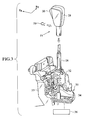
- a steering wheel 22 As shown in Fig. 1, there are provided a steering wheel 22, a meter panel 24 provided on an instrument panel 23, an AT finisher 25, and the like, around a driver's seat 21 of a vehicle 20.
- the AT finisher 25 is provided with a shift lever 28 which is turnable in an anteroposterior direction of the vehicle 20 along a guide hole 27 of a cover 26.
- a shift knob 29 is fitted to an upper part of the shift lever 28.
- the shift lever 28 is firstly fitted to the vehicle 20 and then the AT finisher 25 and the shift knob 29 are fitted sequentially.
- a shift button 30 which is operated for changing positions of the shift lever 28.
- this shift knob 29 is provided with an overdrive switch (O/Dsw) 31.
- a base portion 32 of the shift lever 28 is fitted to a support member 33, which is part of the vehicle body, so as to be turnable in the anteroposterior direction of the vehicle 20.
- a detent 34 for positioning and fixing the shift lever 28.
- the detent 34 performs fixation and release of a position of the shift lever 28 by being engaged with and disengaged from a detent plate 35 which serves as a positioningmeans provided on the support member 33.
- a transmission 36 is operated to change gears in response to a gear position of the shift lever 28.
- the shift knob 29 is fitted to an upper part of the shift lever 28.
- the upper part of the shift lever 28 and the shift knob 29 will be described in detail in Fig. 8.
- a compression rod 37 is housed so as to be movable in an axial direction inside the tubular shift lever 28.
- An upper end 41 of the compression rod 37 is connected to a pull block 39 provided on the upper part of the shift lever 28 through a connection rod 38 which penetrates an upper end plate 42 of the shift lever 28.
- the compression rod 37, the connection rod 38 and the pull block 39 are integrated into an engaging member 40.
- the above-described detent 34 (Fig. 3) is provided at a lower end of the compression rod 37.
- a compression spring 43 wound around the connection rod 38 is interposed between the upper end 41 of the compression rod 37 inside the shift lever 28 and the upper end plate 42 of the shift lever 28.
- the engaging member 40 is biased downward (in a direction in which the detent 34 is engaged with the detent plate 35) by resilience of this compression spring 43.
- a knob body 29a of the shift knob 29 has a fitting hole 29b to allow an upper end of the shift lever 28 to be inserted and fitted thereto.
- a housing 44 of the shift button 30 is buried in the shift knob 29. At a lower end of the housing 44, one end (a lower end in this embodiment) of the shift button 30 is pivotally supported by a spindle 45. The shift button 30 is turnable in an anteroposterior direction around the spindle 45. On an upper part of the housing 44, an upper end of an L-shaped link lever 46 is pivotally supported by a spindle 47. The link lever 46 is also turnable in an anteroposterior direction around the spindle 47.
- the link lever 46 is an integration of a flat plate portion 48 and an arcuate engaging portion 49, and has a convexly-curved shape projecting toward the spindle 45 (projecting almost obliquely downward to the left in the drawing) .
- a chamfer 49a is formed on a tip of the above-described arcuate engaging portion 49 of the link lever 46. It is possible to form a round portion or a semispherical tip instead of the chamfer 49a.
- a pin 50 extending in parallel to the spindles 45 and 47 is fixed to the flat plate portion 48 at a bent portion of the link lever 46.
- the pin 50 is engaged with a long hole 51 which is formed on the shift button 30 and extends approximately in a vertical direction.
- the shift button 30 and the link lever 46 constitute a link mechanism 52.
- the shift button 30 When the shift button 30 is pushed toward a travel path 39a for the pull block 39 which is located in the center of the shift knob 29 and is thereby turned clockwise in the drawing, the link lever 46 is turned in the same direction (counterclockwise in the drawing) in conjunction with the shift button 30 by way of the engagement of the pin 50 with the long hole 51.
- the shift button 30 is biased to be turned outward from the shift knob 29 by resilience of an unillustrated torsion spring which is provided either on the spindle 45 or on the spindle 47.
- An engaging hole 54 for allowing insertion and engagement of the arcuate engaging portion 49 of the link lever 46 is formed on the pull block 39 of the engaging member 40.
- a roundly shaped portion 55 projecting convexly downward at a cross-section in the axial direction is formed on an inner surface on an upper side of the engaging hole 54.
- the roundly shaped portion 55 functions as a guide when the arcuate engaging portion 49 is inserted and, also, as a contact surface for allowing an upper surface 49b of the engaged arcuate engaging portion 49 to contact and slide thereon.
- a slope 56 which faces the link lever 46 is formed on a link lever 46 side of a lower inner surface of the engaging hole 54.
- the slope 56 also functions as a guide when the arcuate engaging portion 49 is inserted.
- a tubular portion 29c is formed below a step difference portion 57 at a lower end of the shift knob 29.
- a pair of stopper holes 58 extending almost perpendicularly to an axis of the tubular portion 29c are formed in mutually opposed positions.
- a pair of guide protrusions 66 protruding inward from the inner circumferential surface are provided in positions which are phase shifted by about 90 degrees relative to the stopper holes 58.
- an approximately U-shaped fixing pin 59 is fitted into the stopper holes 58.
- Protrusions 60 are formed in mutually opposed positions in the vicinities of two free ends of the fixing pin 59 by means of bending so as to be convex inward.
- the protrusions 60 are respectively inserted into the stopper holes 58 of the tubular portion 29c, and protrude inward from the inner circumferential surface of the fitting hole 29b (see Fig. 5).
- a pair of guide grooves 61 are formed inmutually opposedpositions on an outer circumferential portion of the upper end of the shift lever 28 .
- Each of the guide grooves 61 extends approximately in parallel to the axis of the shift lever 28 so as to guide the protrusions 60 of the fixing pin 59 when fitting the shift knob 29 to the shift lever 28.
- An end wall 62 which is approximately perpendicular to the axis of the shift lever 28 is provided at a lower end of each of the guide grooves 61.
- a pair of fixing holes 63 extending almost perpendicularly to the axis of the shift lever 28 are formed in mutually opposed positions below the guide grooves 61 on the outer circumferential surface of the shift lever 28. That is to say, radial stepped portions 64 are formed between the end walls 62 of the guide grooves 61 and the fixing holes 63 on the outer circumferential surface of the shift lever 28.
- a pair of guide slits 65 are provided on the upper end of the shift lever 28 in positions which are phase shifted by about 90 degrees relative to the guide grooves 61.
- the guide slits 65 extend in the axial direction of the shift lever 28 so as to guide the guide protrusions 66 of the tubular portion 29c of the shift knob 29 when fitting the shift knob 29 to the shift lever 28.
- the protrusions 60 of the fixing pin 59 and the end walls 62 of the guide grooves 61 constitute a detection mechanism for detecting that the tip of the arcuate engaging portion 49 formed on the link lever 46 of the shift knob 29 has reached a position in which the tip can be engaged with the engaging hole 54 of the engaging member 40.
- the protrusions 60 of the fixing pin 59 and the end walls 62 of the guide grooves 61 function as a detection mechanism for notifying the operator of a position where it is possible to push the shift button 30.
- the U-shaped fixing pin 59 has to be elastically deformed to be open out. In this event, reactive force is applied to the pushed shift knob 29. Accordingly, the reactive force notifies the operator of proper timing for pushing the shift button 30 and provides the operator with a feeling on what an appropriate pushing force should be.
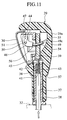
- the shift button 30 is pushed further in order to set a gear position by shifting the shift lever 28 shown in Fig. 10.
- the link lever 46 is further turned counterclockwise in the drawing and thereby lifts up the pull block 39 and the compression rod 37 which is integrated with the bull block 39 (see Fig. 11) .
- the link lever 46 and the arcuate engaging portion 49 form an approximately arcuate shape which is concave relative to the spindle 47. Accordingly, when turning the link lever 46 by pushing the shift button 30 in order to pull up the pull block 39 and the compression rod 37, a turning range of the link lever 46 can be reduced, thus making the shift button 30 compact.
- a portion of the arcuate engaging portion 49 of the link lever 46 located inside the engaging hole 54 of the pull block 39 is inserted almost in parallel to the axial direction of the engaging hole 54 or almost perpendicularly to the pull block 39 at any time when turning the link lever 46. Accordingly, it is possible to reduce a gap between the link lever 46 and the pull block 39 when operating the shift button 30.
- the slope 56 is provided on the lower inner surface of the engaging hole 54 of the pull block 39, it is easier to insert the arcuate engaging portion 49 of the link lever 46 into the predetermined position of the engaging hole 54.
- the slope 56 also functions as a guide for the arcuate engaging portion 49 when detaching the shift knob 29 from the shift lever 28.
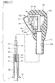
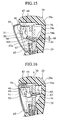
- Figures 12 to 14 show a structure of a shift lever according to the second embodiment of the present invention.
- the same components as those in the first embodiment will be designated by reference numerals and symbols thereof in the first embodiment, and descriptions thereof will be omitted.
- the link lever 46 includes the flatplateportion 48 and a straight engaging portion 67 provided at an end of the flat plate portion 48.
- a chamfer (or a round portion) 67a is formed on a tip of the straight engaging portion 67.
- the engaging hole 54 formed on the pull block 39 is slightly larger than the engaging hole 54 in the first embodiment.
- the rest of the components are the same as those shown in the first embodiment.
- the second embodiment is inferior to the first embodiment in terms of the following points: an increase in the turning range of the link lever 46 requires a larger space for location thereof and an increase in size of the shift knob 29; the larger engaging hole 54 causes a larger gap from a point to start pushing the shift button 30 to a point of application of the pulling force to the pull block 39, and such tendency is significant because the shift button 30 is biased counterclockwise in the drawing by an unillustrated spring; and the loading direction to the link lever 46 in the course of pulling up the pull block 39 is not stabilized but is deviated from the axial direction of the pull block 39, thus requiring more button operating force to be applied to the shift button 30.
- the shift knob 29 in the second embodiment can be manufactured at lower cost than that in the first embodiment because of its simpler shape.
- the free end of the link lever 46 is formed into the arcuate engaging portion 49 as shown in the first embodiment.
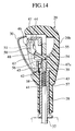
- Fig. 15 shows a state in which an upper inner surface 54a of the engaging hole 54 of the pull block 39 is formed into a cylinder, the straight engaging portion 67 of the link lever 46 is inserted into the engaging hole 54 and the shift button 30 is yet to be pushed in.
- This case causes a large gap 68 from a point to start pushing the shift button 30 to a point of contact of the straight engaging portion 67 of the turned link lever 46 with the upper inner surface 54a of the engaging hole 54. Accordingly, this case causes a large useless motion range from starting pushing the shift button 30 to pulling up the pull block 39.
- the straight engaging portion 67 firstly comes into contact with a corner 54b on a link lever 46 side of the upper inner surface 54a of the engaging hole 54. Then, an upper surface 67a of the straight engaging portion 67 presses the entire upper inner surface 54a and finally presses a corner 54c located on an opposite side of the straight engaging portion 67.
- this embodiment is inferior to the first embodiment in terms of the following points: the contact position between the straight engaging portion 67 of the link lever 46 and the engaging hole 54 of the pull block 39 is shifted when the link lever 46 is turned; an operating direction 69 of the arcuate engaging portion 49 is different from an operating direction 70 of the pull block 39; and, as a result, a direction of action of the force received by the pull block 39 varies depending on the degree of the force to push the shift button 30, thus requiring a device for smoothly moving the pull block 39. Nevertheless, since the engaging hole 54 of the pull block 39 and the link lever 46 have simpler shapes than those in the first embodiment, it is possible to manufacture the shift lever 28 and the shift knob 29 at lower costs.
- a shift lever device includes:
- the link lever 46 can be engaged with the engaging member 40. Since an operation of fitting the knob 29 while pushing the shift button 30 becomes unnecessary, the knob 29 is readily fitted to the shift lever 28, improving efficiency of a fitting operation of the shift lever device.
- the shift lever device includes:
- the detection mechanism includes:
- the elastic member 59 comes into contact with the end wall 62 of the guide groove 61 when the knob 29 is pushed toward the base end of the shift lever 28. Accordingly, it is possible to detect that the shift knob 29 has reached the predetermined position. In other words, the operator can easily recognize the timing for starting pushing the button 30 and increasing the inserting force of the shift knob 29.
- the shift lever 28 is formed to have, in a position below the guide groove 61 on the outer circumferential surface of the distal end thereof, a fixing hole 63 provided for engagement with the protrusion 60 of the elastic member 59, and the protrusion 60 overpasses a stepped portion 64 formed between the fixing hole 63 and the end wall 62 at the terminal end of the guide groove 61 and engages with the fixing hole 63, as the distal end of the shift lever 28 is inserted into the fitting hole 29b of the knob body 29a.
- the elastic member 59 when the elastic member 59 overpasses the stepped portion 64 between the end wall 62 of the guide groove 61 and the fixing hole 63, the elastic member 59 is deformed and insertion resistance of the shift knob 29 is increased. Accordingly, the operator can surely recognize proper timing for pressing the shift button 30 while appropriately adjusting the insertion force of the shift knob 29.
- the link lever 46 is pivoted on the knob body 29a and the second engaging part 49 of the link lever 46 is formed in a concave toward a pivot of the link lever 46.
- the link lever 46 can be inserted to the engaging hole 54 of the engaging member 40 in substantially parallel with an axial direction of the engaging hole 54. Accordingly, it is possible to reduce a gap between the link lever 46 and the engaging member 40 when operating the shift button 30.
- the first engaging part 39 of the engaging member 40 comprises an engaging hole 54, and the second engaging part 49 of the link lever 46 is inserted into the engaging hole 54 for engagement therebetween, and an upper periphery of the engaging hole 54 is formed in a rounded shape 55 in section.
- the roundly shaped portion 55 guides the link lever 46 when the link lever 46 is inserted into the engaging hole 54 of the engaging member 40.
- the first engaging part 39 of the engaging member 40 comprises an engaging hole 54, and the second engaging part 49 of the link lever 46 is inserted into the engaging hole 54 for engagement therebetween, and a lower periphery of the engaging hole 54 is formed to have a slope 56 on a side of the link lever 46.
- the slope 56 guides the link lever 46 when the link lever 46 is inserted into the engaging hole 54 of the engaging member 40.
- a guide protrusion 66 is provided on any one of an outer circumferential surface of the distal end of the shift lever 28 and an inner circumferential surface of the fitting hole 29b of the knob body 29a, and a guide slit/groove 65 is provided for guiding the guide protrusion 66 on the other one of the outer circumferential surface of the distal end of the shift lever 28 and the inner circumferential surface of the fitting hole 29b of the knob body 29a.
- the angular position of the shift knob 29 relative to the shift lever 28 can be regulated when the shift lever 28 is inserted into the shift knob 29. In this way, it is possible to place the link lever 46 of the shift knob 29 so as to face the engaging hole 54 of the engaging member 40 properly.
Landscapes
- Engineering & Computer Science (AREA)
- General Engineering & Computer Science (AREA)
- Mechanical Engineering (AREA)
- Chemical & Material Sciences (AREA)
- Combustion & Propulsion (AREA)
- Transportation (AREA)
- Arrangement Or Mounting Of Control Devices For Change-Speed Gearing (AREA)
Applications Claiming Priority (2)
| Application Number | Priority Date | Filing Date | Title |
|---|---|---|---|
| JP2003165899A JP4101703B2 (ja) | 2003-06-11 | 2003-06-11 | シフトレバー装置 |
| JP2003165899 | 2003-06-11 |
Publications (3)
| Publication Number | Publication Date |
|---|---|
| EP1486702A2 true EP1486702A2 (de) | 2004-12-15 |
| EP1486702A3 EP1486702A3 (de) | 2005-11-02 |
| EP1486702B1 EP1486702B1 (de) | 2012-03-21 |
Family
ID=33296829
Family Applications (1)
| Application Number | Title | Priority Date | Filing Date |
|---|---|---|---|
| EP04253418A Expired - Lifetime EP1486702B1 (de) | 2003-06-11 | 2004-06-09 | Wählhebeleinrichtung |
Country Status (6)
| Country | Link |
|---|---|
| US (1) | US7430940B2 (de) |
| EP (1) | EP1486702B1 (de) |
| JP (1) | JP4101703B2 (de) |
| KR (1) | KR100585929B1 (de) |
| CN (1) | CN1281430C (de) |
| CA (1) | CA2470283C (de) |
Cited By (4)
| Publication number | Priority date | Publication date | Assignee | Title |
|---|---|---|---|---|
| US7546783B2 (en) | 2005-11-17 | 2009-06-16 | Gm Global Technology Operations, Inc. | Motor vehicle shift handle attachment |
| US8960040B2 (en) | 2011-09-14 | 2015-02-24 | GM Global Technology Operations LLC | Electronic shifter with adaptive position |
| US9091340B2 (en) | 2011-05-11 | 2015-07-28 | GM Global Technology Operations LLC | Latching shifter with override feature |
| WO2017177987A1 (de) | 2016-04-13 | 2017-10-19 | Skoda Auto A.S. | Wählhebel des automatikgetriebes eines kraftfahrzeuges |
Families Citing this family (34)
| Publication number | Priority date | Publication date | Assignee | Title |
|---|---|---|---|---|
| JP4384539B2 (ja) * | 2004-05-06 | 2009-12-16 | 株式会社東海理化電機製作所 | シフトレバー |
| JP2006219003A (ja) * | 2005-02-10 | 2006-08-24 | Fuji Kiko Co Ltd | ノブの組付構造 |
| JP4681927B2 (ja) * | 2005-04-19 | 2011-05-11 | 富士機工株式会社 | シフトレバー装置 |
| JP4755843B2 (ja) * | 2005-04-19 | 2011-08-24 | 富士機工株式会社 | シフトレバー装置 |
| JP4729383B2 (ja) * | 2005-10-31 | 2011-07-20 | 富士機工株式会社 | インストルメントパネル置きシフトレバー装置 |
| CN100457494C (zh) * | 2006-12-03 | 2009-02-04 | 林楚华 | 新型横按式换档手柄 |
| JP4958656B2 (ja) * | 2007-06-28 | 2012-06-20 | デルタ工業株式会社 | 自動車用のシフトレバー装置 |
| JP2009018601A (ja) * | 2007-07-10 | 2009-01-29 | Atsumi Tec:Kk | 車両用変速操作装置 |
| CN101980884B (zh) * | 2008-03-28 | 2014-04-23 | 本田技研工业株式会社 | 变速操作装置 |
| US20090301249A1 (en) * | 2008-06-04 | 2009-12-10 | Timothy Smith | Automobile Gear Shifter Kit |
| JP2010052673A (ja) * | 2008-08-29 | 2010-03-11 | Fuji Kiko Co Ltd | シフトレバー装置 |
| KR20110012413A (ko) | 2009-07-30 | 2011-02-09 | 기아자동차주식회사 | 자동변속기용 노브의 원터치 결합구조 |
| KR101081052B1 (ko) * | 2009-12-01 | 2011-11-07 | 에스엘 주식회사 | 버튼식 변속노브를 구비한 변속레버 |
| JP5385866B2 (ja) | 2010-06-30 | 2014-01-08 | 富士機工株式会社 | 車両用シフトレバー装置のシフトノブ装着構造 |
| IT1402587B1 (it) * | 2010-10-29 | 2013-09-13 | Cnh Italia Spa | Dispositivo di controllo e sterzatura per un veicolo a cingoli. |
| KR20120060638A (ko) * | 2010-12-02 | 2012-06-12 | 현대자동차주식회사 | 자동변속기 변속 레버용 노브 |
| KR101355617B1 (ko) * | 2012-10-26 | 2014-01-27 | 현대자동차주식회사 | 변속 레버 |
| JP5973887B2 (ja) * | 2012-11-16 | 2016-08-23 | デルタ工業株式会社 | シフトレバー用ノブのボタン構造 |
| JP6096480B2 (ja) * | 2012-11-16 | 2017-03-15 | デルタ工業株式会社 | シフトレバー用ノブの組み付け構造 |
| KR200472770Y1 (ko) | 2012-12-20 | 2014-05-21 | 주식회사 에스엘 서봉 | 시프트 레버 작동 장치 |
| JP6054787B2 (ja) * | 2013-03-22 | 2016-12-27 | 株式会社アツミテック | 変速操作装置 |
| CN103244662B (zh) * | 2013-05-16 | 2015-07-15 | 安徽江淮汽车股份有限公司 | 一种换挡手柄和换挡杆的连接总成 |
| CN103574011B (zh) * | 2013-10-29 | 2015-12-02 | 奇瑞汽车股份有限公司 | 一种换档手柄连接结构及换档手柄的装配与拆卸方法 |
| KR101596706B1 (ko) * | 2014-11-14 | 2016-02-23 | 현대자동차주식회사 | 동시조작형 전자식 변속레버 및 그 제어방법 |
| JP6496589B2 (ja) * | 2015-03-27 | 2019-04-03 | 株式会社アツミテック | 車両用変速操作装置 |
| JP6148712B2 (ja) * | 2015-11-05 | 2017-06-14 | 株式会社東海理化電機製作所 | シフト装置 |
| CN105422833B (zh) * | 2015-12-21 | 2018-06-26 | 浙江陆虎汽车有限公司 | 用于车辆的换挡操纵机构 |
| JP6557135B2 (ja) * | 2015-12-25 | 2019-08-07 | トヨタ自動車株式会社 | シフトレバー装置 |
| KR101664753B1 (ko) * | 2015-12-30 | 2016-10-12 | 현대자동차주식회사 | 변속 노브 조립체 |
| WO2018096882A1 (ja) * | 2016-11-28 | 2018-05-31 | アルプス電気株式会社 | シフトレバー用取り付けブラケット及びシフトレバー装置 |
| CN109695707B (zh) * | 2017-10-20 | 2021-11-26 | 成都安驭科技有限公司 | 一种具有位置锁定及解锁功能的方法及装置 |
| JP7098253B2 (ja) * | 2018-11-30 | 2022-07-11 | ダイハツ工業株式会社 | シフトレバー装置 |
| CN112549956B (zh) * | 2019-09-25 | 2022-05-06 | 广州汽车集团股份有限公司 | 一种升降式电子换挡器及车辆 |
| US20250278108A1 (en) * | 2024-03-01 | 2025-09-04 | Terex South Dakota, Inc. | Knob mechanism |
Citations (1)
| Publication number | Priority date | Publication date | Assignee | Title |
|---|---|---|---|---|
| DE4434135A1 (de) | 1994-09-24 | 1996-03-28 | Bayerische Motoren Werke Ag | Schalthebel für ein Kraftfahrzeuggetriebe |
Family Cites Families (7)
| Publication number | Priority date | Publication date | Assignee | Title |
|---|---|---|---|---|
| JP3600631B2 (ja) | 1994-03-17 | 2004-12-15 | 富士重工業株式会社 | 自動変速機の変速操作装置 |
| DE4427695A1 (de) * | 1994-08-04 | 1996-02-08 | Bayerische Motoren Werke Ag | Wählhebel für ein Kraftfahrzeuggetriebe |
| JPH11245680A (ja) | 1998-02-27 | 1999-09-14 | Fuji Kiko Co Ltd | シフトレバー装置 |
| DE19941796A1 (de) * | 1999-09-02 | 2001-03-22 | United Parts Fhs Automobil Sys | Wählgriff eines Kraftfahrzeuges |
| DE19950638C2 (de) * | 1999-10-20 | 2001-12-20 | Zf Lemfoerder Metallwaren Ag | Schaltvorrichtung mit einem Schalthebel für ein Automatikgetriebe eines Kraftfahrzeuges |
| JP2002002321A (ja) | 2000-06-27 | 2002-01-09 | Fuji Kiko Co Ltd | シフトレバー装置のシフトノブ構造 |
| JP3916885B2 (ja) | 2001-06-01 | 2007-05-23 | 富士機工株式会社 | シフトノブ装着構造 |
-
2003
- 2003-06-11 JP JP2003165899A patent/JP4101703B2/ja not_active Expired - Lifetime
-
2004
- 2004-06-08 CA CA002470283A patent/CA2470283C/en not_active Expired - Fee Related
- 2004-06-09 EP EP04253418A patent/EP1486702B1/de not_active Expired - Lifetime
- 2004-06-10 US US10/864,871 patent/US7430940B2/en active Active
- 2004-06-11 KR KR1020040042947A patent/KR100585929B1/ko not_active Expired - Fee Related
- 2004-06-11 CN CNB200410049076XA patent/CN1281430C/zh not_active Expired - Fee Related
Patent Citations (1)
| Publication number | Priority date | Publication date | Assignee | Title |
|---|---|---|---|---|
| DE4434135A1 (de) | 1994-09-24 | 1996-03-28 | Bayerische Motoren Werke Ag | Schalthebel für ein Kraftfahrzeuggetriebe |
Cited By (5)
| Publication number | Priority date | Publication date | Assignee | Title |
|---|---|---|---|---|
| US7546783B2 (en) | 2005-11-17 | 2009-06-16 | Gm Global Technology Operations, Inc. | Motor vehicle shift handle attachment |
| DE102006053948B4 (de) * | 2005-11-17 | 2009-11-26 | GM Global Technology Operations, Inc., Detroit | Schaltgriffbefestigungssystem |
| US9091340B2 (en) | 2011-05-11 | 2015-07-28 | GM Global Technology Operations LLC | Latching shifter with override feature |
| US8960040B2 (en) | 2011-09-14 | 2015-02-24 | GM Global Technology Operations LLC | Electronic shifter with adaptive position |
| WO2017177987A1 (de) | 2016-04-13 | 2017-10-19 | Skoda Auto A.S. | Wählhebel des automatikgetriebes eines kraftfahrzeuges |
Also Published As
| Publication number | Publication date |
|---|---|
| CN1281430C (zh) | 2006-10-25 |
| KR100585929B1 (ko) | 2006-06-01 |
| US7430940B2 (en) | 2008-10-07 |
| CA2470283A1 (en) | 2004-12-11 |
| JP2005001470A (ja) | 2005-01-06 |
| EP1486702B1 (de) | 2012-03-21 |
| US20050011293A1 (en) | 2005-01-20 |
| CN1572573A (zh) | 2005-02-02 |
| JP4101703B2 (ja) | 2008-06-18 |
| EP1486702A3 (de) | 2005-11-02 |
| CA2470283C (en) | 2007-10-02 |
| KR20040106253A (ko) | 2004-12-17 |
Similar Documents
| Publication | Publication Date | Title |
|---|---|---|
| EP1486702B1 (de) | Wählhebeleinrichtung | |
| JP4699160B2 (ja) | サイドロック装置 | |
| US8024990B2 (en) | Shift lever apparatus | |
| US5862708A (en) | Shift lever device | |
| US20080098844A1 (en) | Shift lever device | |
| EP2138347A1 (de) | Kopfstütze und fahrzeugsitz mit der kopfstütze | |
| JP4755843B2 (ja) | シフトレバー装置 | |
| JP3934358B2 (ja) | シフトレバー装置 | |
| US5575175A (en) | Shift lever assembly | |
| US20050247159A1 (en) | Shift lever | |
| EP2116150A1 (de) | Kopfstütze und fahrzeugsitz mit der kopfstütze | |
| JP4813386B2 (ja) | シフトレバー装置 | |
| JPH07317890A (ja) | シフトロックユニット | |
| EP1235004A2 (de) | Schalthebel für ein Automatgetriebe | |
| JP2006219003A (ja) | ノブの組付構造 | |
| EP3617558B1 (de) | Schalthebelvorrichtung | |
| JP4694155B2 (ja) | 自動変速機の操作装置 | |
| JP3917215B2 (ja) | シフトレバー装置 | |
| JP4357055B2 (ja) | シフトレバー | |
| JP2006248479A (ja) | 自動変速機用シフトレバー装置 | |
| JP2005119382A (ja) | シフトレバー装置 | |
| JPH09183316A (ja) | 自動車用チェンジレバーの節度ばね取り付け構造 | |
| JP2004090728A (ja) | 車両用シフトレバー装置 | |
| JP2006111248A (ja) | 自動変速機用シフトレバー装置 | |
| JPH10100720A (ja) | 自動変速機の変速操作入力装置 |
Legal Events
| Date | Code | Title | Description |
|---|---|---|---|
| PUAI | Public reference made under article 153(3) epc to a published international application that has entered the european phase |
Free format text: ORIGINAL CODE: 0009012 |
|
| 17P | Request for examination filed |
Effective date: 20040616 |
|
| AK | Designated contracting states |
Kind code of ref document: A2 Designated state(s): AT BE BG CH CY CZ DE DK EE ES FI FR GB GR HU IE IT LI LU MC NL PL PT RO SE SI SK TR |
|
| AX | Request for extension of the european patent |
Extension state: AL HR LT LV MK |
|
| PUAL | Search report despatched |
Free format text: ORIGINAL CODE: 0009013 |
|
| AK | Designated contracting states |
Kind code of ref document: A3 Designated state(s): AT BE BG CH CY CZ DE DK EE ES FI FR GB GR HU IE IT LI LU MC NL PL PT RO SE SI SK TR |
|
| AX | Request for extension of the european patent |
Extension state: AL HR LT LV MK |
|
| AKX | Designation fees paid |
Designated state(s): DE FR GB |
|
| 17Q | First examination report despatched |
Effective date: 20080610 |
|
| GRAP | Despatch of communication of intention to grant a patent |
Free format text: ORIGINAL CODE: EPIDOSNIGR1 |
|
| RIC1 | Information provided on ipc code assigned before grant |
Ipc: F16H 59/10 20060101AFI20110901BHEP Ipc: F16H 59/02 20060101ALN20110901BHEP |
|
| RIN1 | Information on inventor provided before grant (corrected) |
Inventor name: INOUE, KYOICHI Inventor name: INABA, EI Inventor name: NORIMATSU, NAOKI Inventor name: KONDOU, YOSHINOBU |
|
| GRAS | Grant fee paid |
Free format text: ORIGINAL CODE: EPIDOSNIGR3 |
|
| GRAA | (expected) grant |
Free format text: ORIGINAL CODE: 0009210 |
|
| AK | Designated contracting states |
Kind code of ref document: B1 Designated state(s): DE FR GB |
|
| REG | Reference to a national code |
Ref country code: GB Ref legal event code: FG4D |
|
| REG | Reference to a national code |
Ref country code: DE Ref legal event code: R096 Ref document number: 602004036974 Country of ref document: DE Effective date: 20120516 |
|
| PLBE | No opposition filed within time limit |
Free format text: ORIGINAL CODE: 0009261 |
|
| STAA | Information on the status of an ep patent application or granted ep patent |
Free format text: STATUS: NO OPPOSITION FILED WITHIN TIME LIMIT |
|
| 26N | No opposition filed |
Effective date: 20130102 |
|
| REG | Reference to a national code |
Ref country code: DE Ref legal event code: R097 Ref document number: 602004036974 Country of ref document: DE Effective date: 20130102 |
|
| REG | Reference to a national code |
Ref country code: FR Ref legal event code: PLFP Year of fee payment: 13 |
|
| REG | Reference to a national code |
Ref country code: FR Ref legal event code: PLFP Year of fee payment: 14 |
|
| REG | Reference to a national code |
Ref country code: FR Ref legal event code: PLFP Year of fee payment: 15 |
|
| PGFP | Annual fee paid to national office [announced via postgrant information from national office to epo] |
Ref country code: DE Payment date: 20200527 Year of fee payment: 17 Ref country code: FR Payment date: 20200512 Year of fee payment: 17 |
|
| PGFP | Annual fee paid to national office [announced via postgrant information from national office to epo] |
Ref country code: GB Payment date: 20200527 Year of fee payment: 17 |
|
| REG | Reference to a national code |
Ref country code: DE Ref legal event code: R119 Ref document number: 602004036974 Country of ref document: DE |
|
| GBPC | Gb: european patent ceased through non-payment of renewal fee |
Effective date: 20210609 |
|
| PG25 | Lapsed in a contracting state [announced via postgrant information from national office to epo] |
Ref country code: GB Free format text: LAPSE BECAUSE OF NON-PAYMENT OF DUE FEES Effective date: 20210609 Ref country code: DE Free format text: LAPSE BECAUSE OF NON-PAYMENT OF DUE FEES Effective date: 20220101 |
|
| PG25 | Lapsed in a contracting state [announced via postgrant information from national office to epo] |
Ref country code: FR Free format text: LAPSE BECAUSE OF NON-PAYMENT OF DUE FEES Effective date: 20210630 |