EP1381792B1 - Energieführungskette - Google Patents
Energieführungskette Download PDFInfo
- Publication number
- EP1381792B1 EP1381792B1 EP02735042A EP02735042A EP1381792B1 EP 1381792 B1 EP1381792 B1 EP 1381792B1 EP 02735042 A EP02735042 A EP 02735042A EP 02735042 A EP02735042 A EP 02735042A EP 1381792 B1 EP1381792 B1 EP 1381792B1
- Authority
- EP
- European Patent Office
- Prior art keywords
- straps
- energy guiding
- adjacent
- guiding chain
- chain according
- Prior art date
- Legal status (The legal status is an assumption and is not a legal conclusion. Google has not performed a legal analysis and makes no representation as to the accuracy of the status listed.)
- Expired - Lifetime
Links
- 239000000463 material Substances 0.000 claims description 37
- 238000005452 bending Methods 0.000 claims description 14
- 230000033001 locomotion Effects 0.000 claims description 13
- 238000013016 damping Methods 0.000 claims description 8
- 238000013461 design Methods 0.000 claims description 5
- 238000006073 displacement reaction Methods 0.000 claims description 3
- 230000006835 compression Effects 0.000 claims 2
- 238000007906 compression Methods 0.000 claims 2
- 210000001503 joint Anatomy 0.000 description 10
- 230000008859 change Effects 0.000 description 6
- 238000007373 indentation Methods 0.000 description 5
- 230000004048 modification Effects 0.000 description 4
- 238000012986 modification Methods 0.000 description 4
- 238000005299 abrasion Methods 0.000 description 3
- 239000000835 fiber Substances 0.000 description 3
- 238000004519 manufacturing process Methods 0.000 description 3
- 230000007935 neutral effect Effects 0.000 description 3
- 230000003313 weakening effect Effects 0.000 description 3
- 230000005540 biological transmission Effects 0.000 description 2
- 230000015572 biosynthetic process Effects 0.000 description 2
- 238000009434 installation Methods 0.000 description 2
- 230000000670 limiting effect Effects 0.000 description 2
- 230000002829 reductive effect Effects 0.000 description 2
- 238000005096 rolling process Methods 0.000 description 2
- 230000000295 complement effect Effects 0.000 description 1
- 238000010276 construction Methods 0.000 description 1
- 230000003247 decreasing effect Effects 0.000 description 1
- 230000005489 elastic deformation Effects 0.000 description 1
- 230000002452 interceptive effect Effects 0.000 description 1
- 238000012423 maintenance Methods 0.000 description 1
- 238000000034 method Methods 0.000 description 1
- 230000002093 peripheral effect Effects 0.000 description 1
- 230000036316 preload Effects 0.000 description 1
- 230000008569 process Effects 0.000 description 1
- 230000009467 reduction Effects 0.000 description 1
- 230000008439 repair process Effects 0.000 description 1
- 239000004065 semiconductor Substances 0.000 description 1
- 230000008719 thickening Effects 0.000 description 1
- 238000012549 training Methods 0.000 description 1
Images


Classifications
-
- F—MECHANICAL ENGINEERING; LIGHTING; HEATING; WEAPONS; BLASTING
- F16—ENGINEERING ELEMENTS AND UNITS; GENERAL MEASURES FOR PRODUCING AND MAINTAINING EFFECTIVE FUNCTIONING OF MACHINES OR INSTALLATIONS; THERMAL INSULATION IN GENERAL
- F16G—BELTS, CABLES, OR ROPES, PREDOMINANTLY USED FOR DRIVING PURPOSES; CHAINS; FITTINGS PREDOMINANTLY USED THEREFOR
- F16G13/00—Chains
- F16G13/12—Hauling- or hoisting-chains so called ornamental chains
- F16G13/16—Hauling- or hoisting-chains so called ornamental chains with arrangements for holding electric cables, hoses, or the like
-
- H—ELECTRICITY
- H02—GENERATION; CONVERSION OR DISTRIBUTION OF ELECTRIC POWER
- H02G—INSTALLATION OF ELECTRIC CABLES OR LINES, OR OF COMBINED OPTICAL AND ELECTRIC CABLES OR LINES
- H02G11/00—Arrangements of electric cables or lines between relatively-movable parts
- H02G11/006—Arrangements of electric cables or lines between relatively-movable parts using extensible carrier for the cable, e.g. self-coiling spring
Definitions
- the invention relates to an energy guiding chain for guidance of hoses, cables or the like with a number of Chain links, wherein adjacent chain links each articulated connected to each other, the chain links opposite Tabs with inner and outer side surfaces and perpendicular thereto and substantially to the longitudinal direction of the chain have parallel narrow surfaces, at least some of Chain links at least one crosspiece connecting the straps have, the articulation of adjacent chain links is arranged between the narrow surfaces of the tabs and the Energy chain to form a lower strand, a deflection and an upper strand is movable.
- EP 0 789 167 A1 shows cable routing devices known in which the chain links by an elongated flexible band with each other articulated, so that the passage of the cable guide device practically abrasion free. Because the elongated Band at the connecting the tabs of a chain link Transverse webs is attached, are the articulated joints the chain links arranged in the region of the lower ends of the tabs. Thus, the neutral fiber of the routing device, in the deflection of the cable guide device in contrast to the height of the joints spaced areas undergoes no change in length, also arranged at the lower end of the link plates. This However, it is disadvantageous for various applications.
- EP 0 789 167 A1 describes a cable routing from individual mutually pivotable chain links and one within the links between the opposite ones Tabs of the same arranged hinge.
- the invention is therefore based on the object, an energy chain with between the narrow surfaces of the link plates to provide arranged joints that wear and is movable without abrasion and the easy and inexpensive can be produced.
- the object is achieved by an energy guiding chain solved, in which the joints by in Abwinkelungscardi the chain links deformable Joint elements are formed, which are designed as separate components are, wherein the hinge elements are at least partially between the inner and outer side surfaces of the tabs extend.
- the inventive design of the energy chain Abrasion-free operation of the chain is possible, with the joint element Regarding arrangement on the tabs, dimensioning and in particular the choice of materials to the respective requirements adapted optimally and independently of the formation of the tabs can be. So can the tabs and the hinge elements off different materials, especially from different Plastic materials, exist.
- the joint elements can so from a material with high flex life, notch toughness and / or suitable elasticity.
- the elastic Properties of the joint element are preferably so adjusted that the joint element at each intended Bending stress remains in the elastic region and at a deformation elastic restoring forces on the through the Articulated element exerts connected tabs.
- the material of the tabs a particularly high dimensional stability (against tensile, torsional and / or compressive forces) and high bending stiffness of the tabs and also guarantee the chain links in total.
- the Material can have especially a low sliding friction, which is advantageous in energy guiding chains, in which at the passage of the energy chain the upper strand sliding is guided on the lower strand.
- the tabs may be formed so that almost all of them on the energy chain in Record longitudinal compressive and tensile forces while the function of the hinge elements exclusively on the Formation of joints without appreciable stress limited by compressive and tensile forces.
- the hinge elements are elastically deformable.
- the elastically deformable joint element engages in pivoting preferably over the entire pivot angle at both adjacent chain links with elastic restoring forces at.
- the hinge element extends in a stretched arrangement the energy guiding chain preferably straight in the longitudinal direction the same.
- the narrow surfaces are substantially perpendicular to the inner and outer side surfaces of the chain links.
- the joint element extends entirely between the inner and outer side surface of the tabs.
- the width The hinge elements can be exactly the width of the tabs at height correspond to the hinge elements, so that of the tabs laterally projecting portions of the hinge elements are avoided.
- the chain links can each have an upper and lower crosspiece have the space between the opposite tabs to delimit externally, with one of the transverse webs also as Split cross bar can be executed.
- one of the transverse webs also as Split cross bar can be executed.
- the inventive Construction is it z. B. when using intervening Stops also possible, only every second or third etc. chain link to provide transverse webs within the chain.
- the opposite tabs connecting crosspiece can on the Tabs integrally formed or detachable, in particular by means suitable snap-in connections or other fasteners be attached.
- at least one of the transverse webs executed rigid and rigid against the opposite Latches attached.
- the hinge element is in mounting arrangement elongated energy chain in height between the upper and lower cross bar, if any, or the fasteners for transverse webs and at the height of the transverse webs spaced apart, in particular in a middle Range of tab height from the bottom edge of the tabs more than a quarter of the plate height is spaced.
- the hinge element can be arranged at half the height of the tabs be. This allows the chain links symmetrical to the neutral fiber of the energy chain, wherein the neutral fiber in the deflection movement of the chain the stretched in the curved arrangement no change in length experiences. This is advantageous for various applications, because the guided lines in the bending movement the energy chain be claimed evenly.
- the chain links have means for noise damping the noise generated by the actuation of the stops on.
- the noise damping means are preferably as Brakes executed in the area of the stops and / or the corresponding stop surfaces are arranged.
- the noise damping means especially in the attacks Pockets of the corresponding tab arranged be.
- the stop surfaces which at the same time the pockets on the tab ends limit and therefore executed web-like can, may be resilient, for example, by suitable choice of material or material thickness, the material the stop surfaces have a higher modulus of elasticity than the material may have the adjacent tab areas.
- the attacks themselves can be resilient be formed, for example, at least partially from one Material of increased elasticity exist.
- the stops and the corresponding stop surfaces may additionally or alternatively also have a shape, so that a first portion of a stop with a first Part of the corresponding stop surface to a first time and a second portion of the stop with a second portion of the stop surface at a later Time comes to plant, so at the end of the stop process the entire effective area of the stop with the corresponding Stop surface is applied.
- the hinge elements as spring elements executed at a bend of the chain links from the Position with elongated energy chain elastic Apply restoring forces on the adjacent chain links.
- restoring forces can take on a height. that one Return movement of the chain links to the stop position the chain links with elongated energy chain done automatically. This can be for the unloaded as well with at least one institution to be led such as Hose, a line or the like loaded energy supply chain or for the maximum loaded energy chain be valid.
- the joint elements can be designed in many forms. she between the holding areas a changing cross-section and / or regions of different material thickness.
- the cross-section and / or the material thickness increase Distance from the holding areas preferably to and can in be maximum in the central region of the joint element.
- the cross section and / or material thickness can also be based on the respective holding area in a first section to be constant and vary from a distance from the holding area, in particular increase in cross-section and / or material thickness or a material weakening, for example a constriction or have an internal cavity.
- the change the cross section and / or the material thickness are preferably carried out in the main plane of the associated link plates.
- a Cross-sectional change can in particular by a height and / or Side offset of a region of the joint element done.
- a material weakening can be constant or changing cross section of the respective region of the joint element take place, the cross-section increase or decrease can.
- an inner cavity can be at constant or changing Cross section of the joint element be provided, it Can also be a closed or open, especially in mounting position be provided laterally open cavity, the one Material division, in which different strands with a total of constant material thickness can be formed, can correspond.
- the individual strands can have different shapes and be designed, for example, straight or curved and Have indentations and / or bulges, with any combinations possible are.
- the change of the cross section and / or the material thickness can be continuous or stepwise respectively.
- the traversing properties of the energy chain can be adjusted, e.g. the required for bending the tabs Force, whose change with changing pivot angle or the noise damping properties of the joint elements, the on the exercise of restoring forces at the bend can be based. This is especially the case with replaceable ones Joint elements of importance.
- the Chain links should be provided with contact surfaces, the over attack the entire pivot angle on the joint element and here in the case of the elastic deformation of the joint element due to the bending of the chain links on the chain links absorb acting elastic restoring forces.
- the hinge element is press fit between the Arranged contact surfaces.
- the contact surfaces of the tabs as well the corresponding surfaces of the joint element preferably provide plane surfaces whose surface normals parallel to inner and outer side surface of the tabs are and at elongated energy guide chain perpendicular to the longitudinal direction stand the same.
- the joint element can be designed as a plate-like component be, by which a band-shaped component is to be understood.
- the hinge element then has substantially flat top and Bottoms on, facing the top and bottom of the tabs are.
- the link plates lie with areas at the top and / or bottom of the flat areas of the Articulated elements on.
- the joint elements can also others have suitable cross sections.
- the joint element can also be parallel to the plane curved to the inner and outer side surface of the tabs Be formed component so that it in the longitudinal direction straight installation in the tabs a preload in one Abwinkelungsrhythm causes.
- the hinge element can with holding areas on both adjacent Side tabs attack, in the longitudinal direction of the energy chain absorb acting tensile forces.
- the joint element at the adjacent tabs force, shape and / or be firmly bonded.
- the zugaufikide attachment the hinge elements on the tabs can be designed in such a way that this is designed only for low tensile forces, for example to facilitate the installation of the energy chain.
- the holding areas of the joint elements, preferably at the free, the elastically deformable areas opposite ends thereof, top and bottom projections have, extending over the entire width of the hinge elements can extend. To accommodate higher tensile forces can at Need additional zugaufmde funds be provided.
- the respective joint element can be used for the articulated connection of exactly two each other in the longitudinal direction of the energy chain be executed adjacent chain links.
- the joint element can also connect several chain links articulated and about this over the length of a plurality of chain links, for example, three to ten or more chain links extend. It can thus more in the longitudinal direction of the energy chain provided successive hinge elements be, each only chain links of a section of the energy chain connect with each other in an articulated way. This requires in a necessary replacement of a joint element not the Entire energy chain, but only a portion of the same be dismantled. If necessary, the joint elements can become also over the entire length of the energy chain extend.
- connection areas can be in the cross-sectional area be arranged on the tabs and the outside of the chain links to lock.
- the above and below the joint elements arranged areas of the tabs can in this case by a Bridge be connected, so that the tabs integrally formed are.
- the hinge elements in recesses of the link plates arranged.
- the recesses are preferably frontally towards the adjacent flap, by the respective joint element is connected, opened.
- additionally or alternatively, and regardless of the length of the Joint elements can be the recesses receiving the joint elements on the link plates on the side surfaces, the Energy guiding chains inside and / or facing away, towards be open so that the hinge elements in one direction transverse, preferably perpendicular, to the main plane or the side surfaces the tabs in the recesses insertable and on the tabs are fastened.
- the joint element can by frictional, positive and / or cohesive connection with the tabs against a Disassembly of the tabs perpendicular to the main plane of the tabs and / or against rotation transverse to the tabs on these be secured, in particular when the joint element in one is arranged laterally open recess of the tabs.
- At least one, preferably both, the adjacent tabs on the adjacent tab associated end face at the height of the joint element a on the front side open recesses through which the joint element extends.
- the recess extends at least starting from the extended arrangement of the energy chain on the facing the Abwinkelungscardi of the links Side of the joint elements, preferably on both sides of the joint elements.
- the recess preferably extends from the Joint element at the height of the pivot axis of the adjacent tabs to each other, preferably in the amount of flaps and / or in the longitudinal direction of the energy chain over more than half or more than twice the strength of the joint element, for example, about three to five times the strength of the joint element or more.
- Which are facing each other through the two Recesses of the adjacent tabs resulting recess can be a circular, elliptical or other suitable Have shape.
- the longitudinal extension of the recess may be 20 to 60%, preferably 35 to 45%, z. B. about 40% of Length of the joint element or the distance of the joint element be on the tabs securing interlocking means.
- the recess extends starting from the Hinge element only over a portion of the tab height and ends at a distance from the top or bottom edge of the tab.
- the adjacent tabs preferably have cooperating Means acting on the energy chain Absorb pressure and / or tensile forces. This is done a pressure and / or strain relief of the connection areas of Joint elements with the tabs.
- the pressure and / or traction absorbing means as corresponding projections and undercut areas in the form of recesses formed the adjacent tabs.
- the projections are preferably on the inside or outside sides of the tabs arranged and extend laterally from these in the direction on the inside of the energy chain or in the opposite direction Direction.
- the recesses for receiving the projections are in the chain longitudinal direction by a pressure and / or limited zugkraftaufnemdes abutment for the projections, so that absorbed in the longitudinal direction of the chain tensile and / or compressive forces can be.
- the recess may be partially or be completely closed.
- the tensile and / or pressure-absorbing corresponding areas of the adjacent tabs can also be used as corresponding stops to limit the Pivoting angle of the adjacent chain links to each other be executed.
- the tabs in the direction of the adjacent Lugs protruding, this laterally embracing Overlap areas on.
- the overlapping areas can be of one with respect to the chain longitudinal direction middle region of the tabs go out, the wall thickness greater than the wall thickness of the overlapping areas is. Due to the overlapping areas, the Side stability of the energy chain significantly increased.
- the top and bottom of the joint element are arranged by a Middle region of the tab opposite recess from each other separated, with the recess over the entire flap width extends.
- the recess preferably extends also at the height of the respective joint element and can based on a beaten by the joint element center point lying in the Laschenschenteilebene circle a circular segment-shaped Have shape. This allows the length of the tab and thus their weight can be significantly reduced.
- the Overlap areas preferably extend substantially over only the pivot angle of the tabs plus the wall thickness of projections or with these corresponding Investment areas that limit the pivoting angle or act as traction and / or pressure force absorbing means. These Areas are preferably designed web-like and extend perpendicular to the pivoting of the tabs.
- the upper flap facing an adjacent flap and below the hinge element arranged overlapping areas preferably on different sides of the tabs, d. H. on the outside or inside side surface, or on different sides of the central main plane of the tabs arranged.
- the overlapping areas thus have a lateral offset to each other.
- the corresponding overlapping areas of the adjacent tabs are preferably only in each case an overlap region of the respective adjacent tab side across from. As a result, the lateral stability of the energy chain additionally increased.
- At least one or both of the above-mentioned overlapping areas sideways in the direction of the corresponding overlap area the protruding tabs projecting from the adjacent tab be provided, for example, as stops or strain relief or designed as pressure force receiving means can be, without being limited to, so that the neighboring Lugs tilted for mounting about their longitudinal axes or entangled frontally brought together to the plant and then be twisted about their longitudinal axes, around the center of the plane opposite each other Overlap areas laterally to each other to plant bring, with the projections engage behind each other.
- Each on the outside or inside on the tab arranged overlapping areas may be diametrically opposite each other be arranged so that one of the overlapping areas above and another below the articulation is arranged.
- Arrangement and geometry of the overlapping areas can be varied be varied.
- a particularly advantageous embodiment occurs when the tabs have at least two overlap areas are provided, the adjacent tab facing free end faces with a perpendicular to Chain longitudinal direction, lying in the tongue main plane Direction R have different angles W1, W2.
- the end faces are preferably substantially perpendicular to the pivoting direction of the adjacent chain links to each other.
- the overlapping areas are different inclined end faces of only one adjacent tab assigned.
- the tabs can each have 4 overlapping areas each having an adjacent tab facing, the front sides of three or less the overlapping areas perpendicular or substantially perpendicular to the chain longitudinal direction and the front side at least one or more of the overlapping areas inclined to Chain longitudinal direction run.
- the frontal angle to the can be perpendicular to the chain longitudinal direction in this case about 15-60 °, preferably about 30 °.
- each can each have two tabs on one tab Overlap areas, each having a different Angular extension of the above-defined vertical exhibit.
- all overlapping areas extend over the same pivot angle in the Essentially the maximum pivot angle of the adjacent Chain links corresponds to each other.
- the adjacent tabs are at least one Projected from an area of the adjacent tab is overlapped with little or no play, creating a Height offset of the tabs to each other is prevented.
- the game is preferably dimensioned such that the areas in the Swiveling movement of the chain links without contacting each other are guided, whereby abrasion is prevented.
- the height offset the tabs conditional on each other come the cross-over Areas of neighboring flaps attack each other, whereby the height offset is limited.
- the game can be at least in one or reduced two stop positions of the chain links to zero be.
- the height offset preventing projections can act simultaneously as a stop means. You can contact the Overlapping areas or arranged at the central region of the tabs be and inward or outward from the tabs protrude or extend in the main plane of the tabs.
- the projections may be in the region of the upper edge of the tabs, adjacent to the hinge elements or other suitable Be arranged place.
- the Stops can be designed as projections that are in the main plane of the tabs extend and in this case in the longitudinal direction the energy chain from the middle tab area, on which overlapping areas can be formed, protrude. The attacks can also be laterally to the Connect overlapping areas. Of course you can Other suitable stops may be provided.
- the stops are immediately adjacent the hinge elements arranged, causing the attacks with only minor Bow speed impact each other, so that the Energy supply chain can be moved quietly.
- the stops are directly radially outward arranged to recesses, which the respective joint element with Surround game to facilitate the bending of the joint element.
- the stops are at the energy guide chains inside facing side of the middle regions of Lugs arranged and can with the adjacent overlap area have a common side surface. The wall thickness the stop thus corresponds approximately to half the wall thickness of the same mid-range.
- the tabs of a chain link can in the manner of cranked Lugs, which may be mirror symmetrical to each other executed be.
- the energy chain can also be through opposing Tabs made of alternating inner and outer plates or in another suitable way, e.g. B. by forked Lugs, be built.
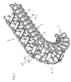
- the energy supply chain 1 according to the invention shown in FIG consists of a variety of articulated interconnected Chain links 2, each of two arranged parallel to each other, mirror symmetrical to each other running tabs. 3 exist, which by each an upper and lower crossbar 4a, 4b are interconnected.
- the transverse webs 4a, 4b are according to the embodiment by locking means releasably on the tabs 3 attached. Due to the dimensionally stable tabs and at least a rigid cross bar, the stably fixed to the tabs. is stable, dimensionally stable, torsional and torsion-resistant chain links educated.
- At least one of the transverse webs at least partially the interior of the energy chain release to the leading hoses, Cable or the like in the through the tabs and crossbars to arrange defined guide channel of the energy chain.
- the illustrated energy chain can under arch Forming a lower run 5, of which only one tab of the first chain link is shown, a deflection region 6 and a top strand 7 are arranged.
- the chain links 2 are interconnected by hinge elements 8 connected, according to the embodiment in each case exactly two mutually adjacent tabs 3 hinged together, which alone form the joint.
- the joint elements 8 are designed as substantially plate-like components, the extend over the entire width of the tabs 3 and flush with the inner and outer side surfaces 9, 10 complete.
- the width and length of the elastically deformable Areas of the joint elements 8 is a multiple the strength of the same.
- the joint elements 8 are arranged in laterally open recesses 11 of the tabs 3, wherein according to the embodiment, the recesses 11 both to the inner and outer side surface 9, 10 out open are.
- the joint elements 8 can thus laterally to the Tabs 3 inserted into the recesses 11 and set in this become.
- the joint element 8 is in the bending direction the chain links elastically deformable and in the manner of a executed hinge-like spring element, in the manner of a Leaf spring acts.
- the joint element 8 exerts after bending the elongated rest position elastic restoring forces on the adjacent link plates so that the link plates completely in their starting position under training an elongated section of the energy chain be returned. But the joint element can also be carried out this way be that essentially no restoring forces exercised be provided for what a hinge-like joint area can be.
- the joint element 8 thus has a middle elastically deformable Area 12 on, between the end faces of the adjacent tabs 2 is arranged and on the two sides Holding areas 13 adjacent, the exact fit to the recess 11 limiting surfaces 14 of the tabs 2 abut.
- the holding areas 13 point away from the central region 12
- Side cross-sectional extensions 15 on which an undercut behind the tab, leaving the hinge elements secured against longitudinal displacement in the recess 11th are arranged. Regardless of this, the joint elements are against a pivoting transverse to the tabs secured, including Positive locking means are provided, which also here through the cross-sectional widening 15, which extends over the entire Width of the hinge elements extends, are provided.
- the holding portions 13 of the hinge elements means, which the hinge elements 8 against a Secure transverse displacement to the tabs 2, which here as additional Positive locking means in the form of a cross-sectional widening 15 introduced over a peripheral area extending groove 16 a are executed (Fig. 2b, d), in which a corresponding projection of the tab 2 engages.
- a cross-sectional widening 15 introduced over a peripheral area extending groove 16 a
- the hinge element is by the embodiment described below the tabs in chain longitudinal direction and / or Transverse tensile and / or compressive forces practically completely relieved.
- the hinge element is arranged at half the height of the tabs 2.
- the distance between the centers of both joint elements of a tab is less than the height of the tab, here about half Height, so that the tabs are formed relatively narrow, which improves the rolling properties of the chain.
- the tabs 2 and which are designed as separate components joint elements 8 made of different plastic materials.
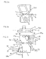
- Fig. 2c At the side of the adjacent tab facing end faces 16, 17 of the tabs (Fig. 2c) are at the level of the hinge elements eighth frontally open recesses 18 provided in the Pull tabs 2 in.
- the recess 18 limiting Edge 19 of the tab has above and below the hinge element 8 at a distance to this, here greater than the strength of the hinge element 8 is such that a bend of the Joint element over a larger bending radius is possible.
- the energy chain When the energy chain is mounted, they complement each other facing recesses 18 of the adjacent tabs to a common recess, extending over the entire length of the elastic deformable central region 12 of the joint element extends.
- the length of the middle deformable area of the joint element corresponds to about 40% of the total length and the quadruple wall thickness of the same.
- the tabs 2 also have according to Figure 2 overlap areas 20 to 23, the pairs with overlapping areas of the two overlap adjacent tabs, reducing lateral stability the chain links is substantially increased.
- the overlapping areas 20 to 23 are from a middle range 24 of the flaps frontally towards the adjacent tabs before, the middle area 24 compared to the overlapping areas has a greater wall thickness.
- Each The adjacent tabs are thus two overlapping areas 20, 22 and 21, 23, respectively, above (20, 21) or below (22, 23) of the joint element 8 are arranged and by extending across the width of the tabs Recess 24b are separated.
- the recess is through here limits the free ends of the overlap areas, so that the tabs can have a small length.
- the overlap areas are each at the inside Side surface 9, the other overlap area, the associated with the same adjacent tab, at the outer Side surface 10 of the tab arranged.
- the overlapping areas 20 and 21 or 22 and 23 are thus on opposite Side of the tongue main plane E (see Figure 2b, d).
- the extent of the overlapping areas 20 to 23 corresponds thus essentially the angular extent of the pivoting angle in addition to the thickness of the projections 25 to 28, as Means for receiving in the longitudinal direction of the energy chain acting tensile and / or compressive forces and independently thereof or at the same time as attacks.
- Three of the end faces 20a, 22a, 23a of the overlapping regions 20, 22, 23 are perpendicular to the longitudinal direction of the energy chain, wherein the fourth end face 21a of the overlapping area 21 with the power transmission chain longitudinal direction an angle W2 includes, which corresponds substantially to the pivoting angle (Figure 2c).
- the overlap region 21 is thus at a essentially perpendicular to the chain longitudinal direction End face of the central tab portion 24 is arranged.
- the Tabs thus essentially have the shape of two skewed Parallelograms on the chain longitudinal direction and are tilted to the opposite direction.
- the faces an overlap area as well as the middle area 24, d. H. the surfaces 21a and 24d are aligned with each other arranged, the surfaces 20a and 22a and 23a and 24e have a longitudinal offset in the direction of the energy chain on (Fig. 2e).
- the middle area 24a of the tabs from which the overlapping areas depart the front side thus points to the chain longitudinal direction inclined end faces on, so that the middle range is on both front sides as well as upper and below the hinge elements in the direction of the upper and lower Tapered surface.
- the middle area exists thus, from two essentially triangular or trapezoidal Areas whose broad base at the height of the hinge elements together lie.
- a gap 45 formed ( Figure 1) in the in a stop position of the chain links an overlap area can engage the adjacent chain link. According to the embodiment, this is for the stop positions in a straight and fully pivoted stop position given.
- each side in Direction to the overlap area of the adjacent flap protruding projections 25 to 28 are arranged, which die.Vorsprünge the laterally opposite overlap region of the adjacent Engage behind tab (Fig. 2d, e).
- the projections 26, 28 of the tab 3 which are diametrically opposed to each other, are here part of an edge of a laterally open Recess 30, 31. Due to the pairwise arrangement of the overlapping areas 20, 23 and 21, 22 on opposite side surfaces the tabs and the side of the overlap areas protruding projections 25 to 28 are the tabs below Rotation of the same from the tongue main plane together preassemblable, after which the joint elements 8 in the Recesses 11 can be inserted laterally.
- the respective adjacent tabs with each other provided in the height cross-projections, at least or only in the stop position of the adjacent Chain links with extended arrangement of the energy chain a height offset of the adjacent tabs or chain links prevent each other.
- the height offset exclusively in the stop position with extended cable drag chain completely prevented, so that during the pivoting movement the chain links to each other a friction of Regions of the chain links is prevented each other.
- position and curvature of the floor-shaped Sections 36, 37 and the facing surfaces 40, 41st the projections 25, 26 chosen so that the adjacent chain links in the stop positions with stretched and / or curved Energy chain wedge together by themselves set the projections on the arcuate surfaces and only against a small force, the movement in the stop position is opposite, are detachable from each other.
- the height game the adjacent tabs has each other in the two Stop positions thus an undersize. This will be in the Stops achieved additional rigidity of the chain.
- the side flaps 2 are with pairs of corresponding stops 50, 51 and 52, 53 (Fig. 2e) provided, the pivoting angle in linear and pivoted position of the Limit chain links to each other.
- the stops are boxy Projections formed by the central areas 24 of the tabs are in the main plane E of the tabs in Direction extend to the opposite tab, wherein according to the embodiment, the above attacks on the Tabs are diametrically opposed and in indentations in the corresponding central areas of the adjacent ones Can intervene tabs.
- the attacks are immediately adjacent to the recesses 18, which surround the hinge elements.
- more surfaces of Tabs as stop surfaces to limit the pivoting movements serve, for example, the frontal surfaces of the Projections 25, 27 or the end faces of the overlapping areas or mid-range 24.
- the stops 50 to 53 on the side facing away from the joint element 8 delimiting surfaces 55, 56 (Fig. 2c) the height offset of the adjacent Limit tabs to each other.
- the pocket-like indentations for receiving as attacks acting projections are as means for noise reduction the noise generated by the actuation of the stops
- Strip 29 of an elastically deformable material with a higher modulus of elasticity than that of the tab material introduced the stop surface 28a for the stop may, for the sake of simplicity, the same Lug is illustrated, which limits the indentation Web 29a be executed elastically deformable, what this from a suitable wall thickness or a material with higher Modulus of elasticity than the adjacent tab sections.
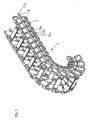
- FIG. 3 shows a modification of the energy guiding chain according to FIG 1, the difference being that the hinge element 8a over several tabs, each 4, and extends several in the chain longitudinal direction immediately following one another Lugs hinged together.
- Between the holding areas 13a of the hinge elements 8a are connecting pieces 13b provided, which has a smaller width than the holding portions 13 a have and are arranged in grooves of the tabs.
- 'A variety of hinge elements 8a is provided to the tabs of a To connect the lashing strip together.
- FIG. 4 shows a modification of a joint element according to FIG 1 and 2, in contrast to this disassembled state is carried out unstretched.
- the hinge element 60 has a Angled middle portion 62, the elastically deformable is, and at the two free ends holding portions 61, for the said to the joint element of Fig. 1 and 2 applies.
- the joint element may also be an arcuate or otherwise have curved shape. It can also be like the joint element 8a according to Figure 3 connect several tabs hinged together.
- the hinge element 60 can be in a stretched arrangement in recesses the tabs are removed and so stretched Apply chain under pretension to the tabs. It can also without bias in correspondingly shaped recesses of Lugs can be arranged.
- the joint element may also be modified by other modification adapted to respective requirements, e.g. through constrictions in the elastically deformable region, e.g. in the way of one Film hinge can be executed.
- Figure 5 shows various joint elements 70 with different Cross sections or material thicknesses between each opposite holding portions 71 for attachment to adjacent Tabs.
- the holding elements in the two right columns differ from those of the two left columns respectively by the between the holding areas 71 and the middle area with different cross-sectional geometries or material thicknesses by connecting portions 72 each having the same Cross section with the same design of the middle joint areas 73-78. It is understood that the design as well the connection areas is variable.
- the hinge region 73 according to FIG. 5a thickens from the retaining regions 71 toward the center of the hinge element in the direction the tongue main plane with mounted hinge element. The thickening takes place here continuously and towards the Center towards decreasing extent.
- the middle hinge portion 74 is arcuate formed, wherein the sheet in the tongue main plane when mounted Joint element is curved.
- the middle hinge portion 75 consists of two oppositely outwardly curved material strands 75a with a intervening cavity 75b open on both sides.
- the strands of material of FIG. 51 as a whole have the strength of the connection area, without being limited thereto.
- Fig. 5n, o shows a joint element with a middle joint area 76 of several, here two, material strands different Geometry.
- One strand of material is rectilinear, the other bent outwards.
- Fig. 5r, s shows a modification of the Gelenkiatasi of FIG. 5n, o where one of the strands of material, here the arched one has indentation pointing to the center line (dashed), the angling in the main plate main plane when mounted Joint element facilitates.
- Fig. 5v, w shows a hinge element in which the middle hinge region 78 at constant outer cross section material weakening in the form of an internal cavity (dashed) has, which is closed here to the outside.
- the middle joint region also be slotted, preferably is the slot plane perpendicular to the main plate plane or Abwinkelungsebene arranged.
Landscapes
- Engineering & Computer Science (AREA)
- General Engineering & Computer Science (AREA)
- Mechanical Engineering (AREA)
- Electric Cable Arrangement Between Relatively Moving Parts (AREA)
- Transmission Devices (AREA)
- Clamps And Clips (AREA)
- Supports For Pipes And Cables (AREA)
- Transition And Organic Metals Composition Catalysts For Addition Polymerization (AREA)
- Rigid Pipes And Flexible Pipes (AREA)
- Details Of Indoor Wiring (AREA)
- Luminescent Compositions (AREA)
- Saccharide Compounds (AREA)
- Secondary Cells (AREA)
- Valve Device For Special Equipments (AREA)
- Valve-Gear Or Valve Arrangements (AREA)
- Steering Controls (AREA)
- Materials For Medical Uses (AREA)
- Glass Compositions (AREA)
- Addition Polymer Or Copolymer, Post-Treatments, Or Chemical Modifications (AREA)
- Harvester Elements (AREA)
- Orthopedics, Nursing, And Contraception (AREA)
- Surgical Instruments (AREA)
- Crystals, And After-Treatments Of Crystals (AREA)
- Radiation-Therapy Devices (AREA)
Priority Applications (1)
| Application Number | Priority Date | Filing Date | Title |
|---|---|---|---|
| EP04026502.7A EP1503107B2 (de) | 2001-04-23 | 2002-04-15 | Gelenkelement für Energieführungskette |
Applications Claiming Priority (3)
| Application Number | Priority Date | Filing Date | Title |
|---|---|---|---|
| DE20107003U DE20107003U1 (de) | 2001-04-23 | 2001-04-23 | Energieführungskette |
| DE20107003U | 2001-04-23 | ||
| PCT/DE2002/001407 WO2002086349A1 (de) | 2001-04-23 | 2002-04-15 | Energieführungskette |
Related Child Applications (2)
| Application Number | Title | Priority Date | Filing Date |
|---|---|---|---|
| EP04026502.7A Division EP1503107B2 (de) | 2001-04-23 | 2002-04-15 | Gelenkelement für Energieführungskette |
| EP04026502.7 Division-Into | 2004-11-09 |
Publications (2)
| Publication Number | Publication Date |
|---|---|
| EP1381792A1 EP1381792A1 (de) | 2004-01-21 |
| EP1381792B1 true EP1381792B1 (de) | 2005-01-12 |
Family
ID=7956107
Family Applications (2)
| Application Number | Title | Priority Date | Filing Date |
|---|---|---|---|
| EP02735042A Expired - Lifetime EP1381792B1 (de) | 2001-04-23 | 2002-04-15 | Energieführungskette |
| EP04026502.7A Expired - Lifetime EP1503107B2 (de) | 2001-04-23 | 2002-04-15 | Gelenkelement für Energieführungskette |
Family Applications After (1)
| Application Number | Title | Priority Date | Filing Date |
|---|---|---|---|
| EP04026502.7A Expired - Lifetime EP1503107B2 (de) | 2001-04-23 | 2002-04-15 | Gelenkelement für Energieführungskette |
Country Status (13)
| Country | Link |
|---|---|
| US (1) | US6745555B2 (enExample) |
| EP (2) | EP1381792B1 (enExample) |
| JP (2) | JP4167493B2 (enExample) |
| KR (1) | KR100517779B1 (enExample) |
| CN (2) | CN100585219C (enExample) |
| AT (2) | ATE287051T1 (enExample) |
| BR (1) | BR0209156B1 (enExample) |
| CA (1) | CA2445267C (enExample) |
| CZ (1) | CZ299406B6 (enExample) |
| DE (4) | DE20107003U1 (enExample) |
| ES (2) | ES2236520T3 (enExample) |
| PL (1) | PL205580B1 (enExample) |
| WO (1) | WO2002086349A1 (enExample) |
Cited By (9)
| Publication number | Priority date | Publication date | Assignee | Title |
|---|---|---|---|---|
| DE202013105149U1 (de) | 2013-11-14 | 2013-11-27 | Igus Gmbh | Leitungsführung |
| DE202014101546U1 (de) | 2014-04-01 | 2014-05-26 | Igus Gmbh | Strangartige Leitungsführungseinrichtung, insbesondere für Kapillarröhrchen oder dergleichen |
| DE202016000501U1 (de) | 2016-01-28 | 2017-03-02 | Igus Gmbh | Energieführungskette oder Leitungsführungseinrichtung mit elektrotechnischer Verschleißerkennung |
| WO2017129805A1 (de) | 2016-01-28 | 2017-08-03 | Igus Gmbh | LEITUNGSFÜHRUNGSEINRICHTUNG MIT ELEKTROTECHNISCHER VERSCHLEIßERKENNUNG UND FUNKSCHALTUNG HIERFÜR |
| DE102007010746B4 (de) * | 2006-03-28 | 2021-03-25 | Tsubakimoto Chain Co. | Schutz- und Führungsvorrichtung für ein Kabel |
| RU203305U1 (ru) * | 2021-01-11 | 2021-03-30 | Российская Федерация, от имени которой выступает Государственная корпорация по атомной энергии "Росатом" | Устройство для перемещения кабелей |
| DE202020103050U1 (de) | 2020-05-27 | 2021-09-02 | Igus Gmbh | Leitungsführungseinrichtung, insbesondere Energieführungskette, und Kettenglied mit Dämpfungselementen |
| DE102006039334B4 (de) | 2005-09-29 | 2024-04-25 | Tsubakimoto Chain Co. | Schutz- und Führungsvorrichtung für ein Kabel |
| DE202023100342U1 (de) | 2023-01-24 | 2024-04-25 | Igus Gmbh | Leitungsführungsvorrichtung mit einteiligen Längsabschnitten und Führungsstück hierfür |
Families Citing this family (75)
| Publication number | Priority date | Publication date | Assignee | Title |
|---|---|---|---|---|
| US7195154B2 (en) * | 2001-09-21 | 2007-03-27 | Privasys, Inc. | Method for generating customer secure card numbers |
| JP3722477B2 (ja) | 2002-04-02 | 2005-11-30 | 株式会社椿本チエイン | ケーブル類保護案内ガイド |
| JP4136905B2 (ja) | 2003-11-13 | 2008-08-20 | 株式会社椿本チエイン | 水平設置型ケーブル保護案内装置 |
| DE202004005808U1 (de) * | 2004-04-08 | 2004-06-17 | Igus Spritzgussteile für die Industrie GmbH | Energieführungskette |
| DE202004005800U1 (de) * | 2004-04-08 | 2005-08-25 | Igus Gmbh | Energieführungskette |
| US7693553B2 (en) * | 2004-06-30 | 2010-04-06 | Avaya Inc. | Intelligent ringtone service |
| US20060003813A1 (en) * | 2004-06-30 | 2006-01-05 | Seligmann Doree D | Intelligent ringtones |
| US7023217B1 (en) | 2004-12-16 | 2006-04-04 | Honeywell International Inc. | Method and apparatus for determining wear of resistive and conductive elements |
| JP4111958B2 (ja) | 2005-03-11 | 2008-07-02 | 株式会社椿本チエイン | ケーブル類保護案内装置 |
| DE202005005826U1 (de) | 2005-04-11 | 2005-06-16 | Igus Gmbh | Leitungsführungseinrichtung und System bestehend aus einer Leitungsführungseinrichtung und einer diese aufnehmenden Haltevorrichtung |
| JP4376822B2 (ja) * | 2005-04-22 | 2009-12-02 | 川崎重工業株式会社 | 変形構造体およびケーブルの支持装置 |
| DE102005038356A1 (de) * | 2005-08-11 | 2007-02-22 | Multivac Sepp Haggenmüller Gmbh & Co. Kg | Kette für einen Maschinenantrieb, einen Materialtransport in einer Maschine oder dergleichen und Verpackungsmaschine mit einer solchen Kette |
| DE102005046194B4 (de) * | 2005-09-27 | 2014-05-15 | S-Y Systems Technologies Europe Gmbh | Kabelkanal mit Kanalsegmenten |
| KR100587499B1 (ko) * | 2005-10-18 | 2006-06-08 | 씨피시스템(주) | 클린룸 체인 |
| JP4137117B2 (ja) * | 2005-12-27 | 2008-08-20 | 株式会社椿本チエイン | ケーブル保護案内装置 |
| JP4111976B2 (ja) | 2006-01-19 | 2008-07-02 | 株式会社椿本チエイン | ケーブル類保護案内装置 |
| DE102006060252B4 (de) | 2006-01-19 | 2024-09-05 | Tsubakimoto Chain Co. | Schutz- und Führungsvorrichtung für ein Kabel oder einen Schlauch |
| JP4789632B2 (ja) * | 2006-01-20 | 2011-10-12 | 株式会社椿本チエイン | ケーブル類保護案内装置 |
| KR100591274B1 (ko) * | 2006-01-23 | 2006-06-19 | 김두진 | 저소음 및 내구성 기능을 구비하는 로보체인 |
| US7240477B1 (en) | 2006-03-20 | 2007-07-10 | Dade Behring Inc. | Flexible router for liquid tubes and electrical ribbon cables |
| JP4118308B2 (ja) * | 2006-04-14 | 2008-07-16 | 株式会社椿本チエイン | ケーブル類保護案内装置 |
| DE202006009482U1 (de) * | 2006-06-17 | 2007-10-11 | Igus Gmbh | Gelenkelement für Energieführungskette |
| EP2091436A1 (en) * | 2006-11-03 | 2009-08-26 | Koninklijke Philips Electronics N.V. | Multiple rotation c-arm |
| DE102007017940A1 (de) | 2007-04-13 | 2008-10-16 | Igus Gmbh | Seitenwandsegment für eine Leitungsführungseinrichtung, Leitungsführungseinrichtung mit Seitenwandsegment und Verfahren zur Herstellung des Seitenwandsegmentes |
| JP4118314B1 (ja) * | 2007-04-27 | 2008-07-16 | 株式会社椿本チエイン | ケーブル類保護案内装置 |
| JP2008281165A (ja) * | 2007-05-14 | 2008-11-20 | Tsubakimoto Chain Co | ケーブル類保護案内装置 |
| JP5197626B2 (ja) * | 2007-12-10 | 2013-05-15 | 株式会社島精機製作所 | ケーブルドラグチェーン |
| EP2077403B1 (en) * | 2008-01-03 | 2012-03-07 | Hanshin Chain Co. | Energy guiding chain having low noise and good durability |
| US7934362B2 (en) | 2008-03-28 | 2011-05-03 | Cp Packaging, Inc. | Belt driven clamping arrangement for gripping and advancing web material in a packaging machine |
| JP4503658B2 (ja) * | 2008-04-25 | 2010-07-14 | 株式会社椿本チエイン | ケーブル類保護案内装置 |
| US8991147B2 (en) * | 2008-08-05 | 2015-03-31 | International Business Machines Corporation | Augmented track to facilitate removal of stiffening layers from a cable retained in the track |
| KR101018293B1 (ko) * | 2009-03-04 | 2011-03-04 | 주식회사 코닥트 | 소음과 분진의 저감 및 바디의 처짐을 완화한 케이블 베어 |
| US7841566B2 (en) * | 2009-03-10 | 2010-11-30 | Cablofil, Inc. | Device and method for suspending and retaining telecommunication and power cables within a building |
| KR100985193B1 (ko) * | 2009-12-29 | 2010-10-05 | 씨피시스템(주) | 클린룸용 케이블 보호장치 |
| DE202011004785U1 (de) | 2011-04-01 | 2011-07-07 | igus GmbH, 51147 | Energieführungskette mit deformierbaren Gelenkelementen |
| JP5430693B2 (ja) | 2012-02-17 | 2014-03-05 | 株式会社椿本チエイン | ケーブル類保護案内装置 |
| KR101196888B1 (ko) | 2012-05-07 | 2012-11-01 | (주)한신체인 | 로보체인과 이에 사용되는 연결 부재 |
| DE202012010236U1 (de) | 2012-10-26 | 2012-11-23 | Igus Gmbh | Energieführungskette mit Spann- bzw. Tragvorrichtung |
| EP2916680B1 (en) | 2012-11-06 | 2018-12-26 | Boa Technology Inc. | Devices and methods for adjusting the fit of footwear |
| DE202013101203U1 (de) * | 2013-03-20 | 2013-03-26 | Igus Gmbh | Energieführungskette insbesondere für Reinraumanwendungen |
| DE202013101421U1 (de) | 2013-04-03 | 2013-04-23 | Igus Gmbh | Öffnungshilfe |
| DE202013101604U1 (de) * | 2013-04-16 | 2013-05-07 | Igus Gmbh | Energieführungseinrichtung |
| JP6175402B2 (ja) * | 2014-04-04 | 2017-08-02 | 株式会社椿本チエイン | ケーブル類保護案内装置 |
| ES2886156T3 (es) | 2014-09-18 | 2021-12-16 | Igus Gmbh | Equipo de guiado de líneas, en particular para aplicaciones de sala blanca, partes de carcasa y nervaduras de apoyo para ello. |
| DE202014104458U1 (de) | 2014-09-18 | 2014-09-25 | Igus Gmbh | Energieführungseinrichtung insbesondere für Reinraumanwendungen |
| DE202015100472U1 (de) * | 2015-02-02 | 2015-02-10 | Igus Gmbh | Kettenglied und Kreiskette mit Kettenglied |
| US9851523B2 (en) | 2015-09-22 | 2017-12-26 | Go!Foton Holdings, Inc. | Apparatus for cable routing |
| KR102432862B1 (ko) * | 2015-12-15 | 2022-08-18 | 삼성전자주식회사 | 조인트 어셈블리 및 이를 포함하는 운동 보조 장치 |
| DE202016104470U1 (de) * | 2016-08-12 | 2017-11-14 | Igus Gmbh | Verbindungsvorrichtung und Leitungsführungseinrichtung |
| DE202017101099U1 (de) * | 2017-02-27 | 2017-03-14 | Igus Gmbh | Energieführungskette und Rollenmodul |
| US10367339B2 (en) * | 2017-05-10 | 2019-07-30 | The Boeing Company | Snag mitigating cable track apparatus |
| US10310206B2 (en) * | 2017-05-22 | 2019-06-04 | Go!Foton Holdings, Inc. | Apparatus for cable routing |
| CN107565494B (zh) * | 2017-09-27 | 2024-02-02 | 中国电子科技集团公司第五十四研究所 | 一种平面内旋转运动有限角度走线装置 |
| DE202018101686U1 (de) * | 2018-03-26 | 2018-04-09 | Igus Gmbh | Energieführungskette und Trennsteg hierfür |
| KR102017509B1 (ko) * | 2018-04-12 | 2019-10-21 | 주식회사 성엔지니어링 | 케이블 베어 |
| DE202018102144U1 (de) * | 2018-04-18 | 2019-05-27 | Igus Gmbh | Energieführungskette mit Dämpfungselementen sowie Seitenteil dafür |
| DE202018102239U1 (de) | 2018-04-21 | 2019-05-23 | Igus Gmbh | Energieführungskette mit Verschleißerkennung |
| KR102051598B1 (ko) * | 2018-09-06 | 2019-12-04 | 주식회사 코닥트 | 케이블 캐리어 |
| DE202018106543U1 (de) | 2018-11-19 | 2019-12-20 | Igus Gmbh | System zur Leitungsüberwachung in einer Leitungsführungseinrichtung, insbesondere in einer Energieführungskette |
| SG11202108321SA (en) | 2019-01-14 | 2021-08-30 | Igus Gmbh | Compact protective cable conduit for clean room applications and encasing unit and clamping device for same |
| DE202019103276U1 (de) | 2019-06-11 | 2020-02-20 | Igus Gmbh | Kompakte Leitungsschutzführung für Reinraumanwendungen sowie Hülleinheit und Klemmvorrichtung hierfür |
| DE202019100169U1 (de) * | 2019-01-14 | 2020-02-20 | Igus Gmbh | Kompakte flexible Leitungsschutzführung, insbesondere für Reinraumanwendungen |
| DE102019108709B4 (de) * | 2019-04-03 | 2025-11-13 | Maximilian Rüttiger | Energiekette mit Filmscharnier |
| FR3096841B1 (fr) * | 2019-05-28 | 2022-04-22 | Newtl | Dispositif de gestion du frottement d’un conducteur sur un séparateur |
| DE202019103068U1 (de) | 2019-05-29 | 2020-06-30 | Igus Gmbh | Leitungsführungseinrichtung für Reinraumanwendungen |
| US20210023400A1 (en) * | 2019-07-22 | 2021-01-28 | Ramil Ravilyevich Musakaev | Seat for safety harness |
| KR102139096B1 (ko) | 2020-02-10 | 2020-07-29 | 주식회사 서현전자산업 | 에너지 체인용 조인트 |
| EP4158223B1 (de) * | 2020-05-27 | 2024-07-03 | Igus GmbH | Energieführungskette mit biegsamen gelenkverbindern, sowie seitenlaschen und gelenkverbinder hierfür |
| DE202020103046U1 (de) | 2020-05-27 | 2021-09-02 | Igus Gmbh | Energieführungskette |
| DE202021101933U1 (de) | 2021-04-09 | 2022-07-21 | Igus Gmbh | Energieführungskette mit biegsamen Gelenkverbindern, sowie Seitenlaschen und Gelenkverbinder hierfür |
| US11283250B2 (en) | 2020-07-24 | 2022-03-22 | Cablofil, Inc. | Slider bracket assembly |
| DE202020105039U1 (de) | 2020-09-01 | 2021-10-04 | Igus Gmbh | Energieführungskette mit leitungsschonender Innenaufteilung sowie Kettenglied und Rahmenmodul hierfür |
| EP3968476B1 (en) | 2020-09-14 | 2023-08-23 | Nasekomo B.V. | Guiding chain carrier system |
| CN112260174A (zh) * | 2020-10-31 | 2021-01-22 | 江苏科瑞斯机件有限公司 | 快速拆装穿线导链 |
| CN117420690B (zh) * | 2023-12-19 | 2024-04-09 | 玩出梦想(上海)科技有限公司 | 头戴式显示设备 |
Family Cites Families (19)
| Publication number | Priority date | Publication date | Assignee | Title |
|---|---|---|---|---|
| JPS5884243A (ja) * | 1981-11-16 | 1983-05-20 | Mitsubishi Heavy Ind Ltd | 駆動用チエン |
| JPS60101251U (ja) * | 1983-12-16 | 1985-07-10 | 株式会社椿本チエイン | 合成樹脂製サイドカ−ブチエ−ン |
| JPS60101251A (ja) * | 1984-07-23 | 1985-06-05 | Mitsubishi Electric Corp | スタ−リング機関 |
| DE3431531A1 (de) * | 1984-08-28 | 1986-03-06 | Igus GmbH, 5060 Bergisch Gladbach | Energiezufuehrungskette |
| DE3507200A1 (de) * | 1985-03-01 | 1986-09-04 | Kabelschlepp Gmbh, 5900 Siegen | Energiefuehrungskette |
| DE3516448C1 (de) * | 1985-05-08 | 1986-09-25 | Murr-Plastik Gmbh, 7155 Oppenweiler | Energieführungskette |
| DE3522885A1 (de) | 1985-06-26 | 1987-01-08 | Gebr Hennig Gmbh | Energiefuehrungskette |
| JPS62158246A (ja) * | 1986-01-06 | 1987-07-14 | Showa Denko Kk | アミノ酸の脱色法 |
| JPH0223886Y2 (enExample) * | 1986-03-31 | 1990-06-29 | ||
| DD249742A1 (de) | 1986-06-09 | 1987-09-16 | Wismar Ing Hochschule | Kabel- und schlauchschlepp, bestehend aus gelenkigen gliedern |
| IT208046Z2 (it) * | 1986-09-15 | 1988-03-31 | Tecno Mobili E Forniture Per A | Organo passocavo flessibile a snodi bidirezionali. |
| GB2208129B (en) * | 1987-07-01 | 1991-08-21 | Mansign Eng | Cable handling chain |
| AU693607B2 (en) * | 1994-10-18 | 1998-07-02 | Smed, Inc | Cable carriers |
| DE19541928C1 (de) * | 1995-11-10 | 1997-06-12 | Igus Gmbh | Energieführungskette |
| US5836148A (en) * | 1996-02-06 | 1998-11-17 | Kunimorikagaku Ltd. | Cable chain |
| DE19605775C1 (de) * | 1996-02-16 | 1997-09-25 | Igus Gmbh | Energieführungskette mit Führungsanschlag |
| DK174401B1 (da) * | 1997-05-15 | 2003-02-10 | Raunkjaer Hans Thyge | System til fremføring af bundter af ledninger |
| DE19915035C2 (de) | 1999-04-01 | 2001-08-09 | Kabelschlepp Gmbh | Leitungsführungselement zum Führen wenigstens einer Leitung |
| DE10116403B4 (de) | 2001-04-02 | 2004-08-26 | Ekd Gelenkrohr Gmbh | Energieführungskette |
-
2001
- 2001-04-23 DE DE20107003U patent/DE20107003U1/de not_active Expired - Lifetime
-
2002
- 2002-04-15 CA CA002445267A patent/CA2445267C/en not_active Expired - Lifetime
- 2002-04-15 PL PL363314A patent/PL205580B1/pl unknown
- 2002-04-15 AT AT02735042T patent/ATE287051T1/de not_active IP Right Cessation
- 2002-04-15 DE DE10291748T patent/DE10291748D2/de not_active Expired - Fee Related
- 2002-04-15 US US10/123,820 patent/US6745555B2/en not_active Expired - Lifetime
- 2002-04-15 EP EP02735042A patent/EP1381792B1/de not_active Expired - Lifetime
- 2002-04-15 WO PCT/DE2002/001407 patent/WO2002086349A1/de not_active Ceased
- 2002-04-15 CZ CZ20032862A patent/CZ299406B6/cs not_active IP Right Cessation
- 2002-04-15 CN CN200610094007A patent/CN100585219C/zh not_active Expired - Lifetime
- 2002-04-15 JP JP2002583846A patent/JP4167493B2/ja not_active Expired - Lifetime
- 2002-04-15 AT AT04026502T patent/ATE384213T1/de not_active IP Right Cessation
- 2002-04-15 BR BRPI0209156-9A patent/BR0209156B1/pt not_active IP Right Cessation
- 2002-04-15 KR KR10-2003-7013831A patent/KR100517779B1/ko not_active Expired - Lifetime
- 2002-04-15 CN CNB028108566A patent/CN1289837C/zh not_active Expired - Lifetime
- 2002-04-15 DE DE50211578T patent/DE50211578D1/de not_active Expired - Lifetime
- 2002-04-15 EP EP04026502.7A patent/EP1503107B2/de not_active Expired - Lifetime
- 2002-04-15 ES ES02735042T patent/ES2236520T3/es not_active Expired - Lifetime
- 2002-04-15 ES ES04026502.7T patent/ES2300691T5/es not_active Expired - Lifetime
- 2002-04-15 DE DE50201998.0T patent/DE50201998C5/de not_active Expired - Lifetime
-
2007
- 2007-07-02 JP JP2007173717A patent/JP4768678B2/ja not_active Expired - Lifetime
Cited By (12)
| Publication number | Priority date | Publication date | Assignee | Title |
|---|---|---|---|---|
| DE102006039334B4 (de) | 2005-09-29 | 2024-04-25 | Tsubakimoto Chain Co. | Schutz- und Führungsvorrichtung für ein Kabel |
| DE102007010746B4 (de) * | 2006-03-28 | 2021-03-25 | Tsubakimoto Chain Co. | Schutz- und Führungsvorrichtung für ein Kabel |
| DE202013105149U1 (de) | 2013-11-14 | 2013-11-27 | Igus Gmbh | Leitungsführung |
| DE202014101546U1 (de) | 2014-04-01 | 2014-05-26 | Igus Gmbh | Strangartige Leitungsführungseinrichtung, insbesondere für Kapillarröhrchen oder dergleichen |
| EP2937610A1 (de) | 2014-04-01 | 2015-10-28 | Igus GmbH | Strangartige leitungsführungseinrichtung, insbesondere für kapillarröhrchen oder dergleichen |
| DE202016000501U1 (de) | 2016-01-28 | 2017-03-02 | Igus Gmbh | Energieführungskette oder Leitungsführungseinrichtung mit elektrotechnischer Verschleißerkennung |
| WO2017129805A1 (de) | 2016-01-28 | 2017-08-03 | Igus Gmbh | LEITUNGSFÜHRUNGSEINRICHTUNG MIT ELEKTROTECHNISCHER VERSCHLEIßERKENNUNG UND FUNKSCHALTUNG HIERFÜR |
| DE202020103050U1 (de) | 2020-05-27 | 2021-09-02 | Igus Gmbh | Leitungsführungseinrichtung, insbesondere Energieführungskette, und Kettenglied mit Dämpfungselementen |
| WO2021240007A1 (de) | 2020-05-27 | 2021-12-02 | Igus Gmbh | Leitungsführungseinrichtung, insbesondere energieführungskette, und kettenglied mit dämpfungselementen |
| RU203305U1 (ru) * | 2021-01-11 | 2021-03-30 | Российская Федерация, от имени которой выступает Государственная корпорация по атомной энергии "Росатом" | Устройство для перемещения кабелей |
| DE202023100342U1 (de) | 2023-01-24 | 2024-04-25 | Igus Gmbh | Leitungsführungsvorrichtung mit einteiligen Längsabschnitten und Führungsstück hierfür |
| WO2024156614A1 (de) | 2023-01-24 | 2024-08-02 | Igus Gmbh | Leitungsführungsvorrichtung mit einteiligen längsabschnitten und führungsstück hierfür |
Also Published As
Similar Documents
| Publication | Publication Date | Title |
|---|---|---|
| EP1381792B1 (de) | Energieführungskette | |
| EP1256153B1 (de) | Energieführungskette | |
| EP2694841B1 (de) | Energieführungskette mit deformierbaren gelenkelementen | |
| EP0803032B1 (de) | Energieführungskette | |
| EP0819226B1 (de) | Energiekette | |
| EP1283381B1 (de) | Energieführungskette und Kettenglied | |
| EP2799738B1 (de) | Rückensteife Kette | |
| EP4158223B1 (de) | Energieführungskette mit biegsamen gelenkverbindern, sowie seitenlaschen und gelenkverbinder hierfür | |
| EP2029913A1 (de) | Gelenkelement für energieführungskette | |
| EP2007999A1 (de) | Energieführungskette mit angeformtem gleitschuh | |
| EP3497763B1 (de) | Verbindungsvorrichtung und leitungsführungseinrichtung | |
| EP1084070B1 (de) | Transportkette | |
| EP3894720B1 (de) | Betriebsfest ausgelegte seitenlasche für eine energieführungskette | |
| DE202020103046U1 (de) | Energieführungskette | |
| EP1757838A1 (de) | Rückensteife Antriebskette | |
| EP4139586B1 (de) | Leitungsführungseinrichtung, insbesondere energieführungskette, und kettenglied mit dämpfungselementen | |
| DE202021101933U1 (de) | Energieführungskette mit biegsamen Gelenkverbindern, sowie Seitenlaschen und Gelenkverbinder hierfür | |
| EP4515645A1 (de) | Leitungsführungsvorrichtung und stützkette für reinraumanwendungen | |
| WO2005098267A1 (de) | Energieführungskette | |
| WO2005021997A1 (de) | Abdeckung für eine energieführungskette sowie kettenglied und energieführungskette | |
| DE19740896A1 (de) | Kettenglied mit verschwenkbarem Steg | |
| DE19919075A1 (de) | Energieführungskette |
Legal Events
| Date | Code | Title | Description |
|---|---|---|---|
| PUAI | Public reference made under article 153(3) epc to a published international application that has entered the european phase |
Free format text: ORIGINAL CODE: 0009012 |
|
| 17P | Request for examination filed |
Effective date: 20031017 |
|
| AK | Designated contracting states |
Kind code of ref document: A1 Designated state(s): AT BE CH CY DE DK ES FI FR GB GR IE IT LI LU MC NL PT SE TR |
|
| AX | Request for extension of the european patent |
Extension state: AL LT LV MK RO SI |
|
| GRAP | Despatch of communication of intention to grant a patent |
Free format text: ORIGINAL CODE: EPIDOSNIGR1 |
|
| RIN1 | Information on inventor provided before grant (corrected) |
Inventor name: BLASE, GUENTER Inventor name: HERMEY, ANDREAS Inventor name: BLASE, FRANK |
|
| GRAS | Grant fee paid |
Free format text: ORIGINAL CODE: EPIDOSNIGR3 |
|
| GRAA | (expected) grant |
Free format text: ORIGINAL CODE: 0009210 |
|
| AK | Designated contracting states |
Kind code of ref document: B1 Designated state(s): AT BE CH CY DE DK ES FI FR GB GR IE IT LI LU MC NL PT SE TR |
|
| PG25 | Lapsed in a contracting state [announced via postgrant information from national office to epo] |
Ref country code: NL Free format text: LAPSE BECAUSE OF FAILURE TO SUBMIT A TRANSLATION OF THE DESCRIPTION OR TO PAY THE FEE WITHIN THE PRESCRIBED TIME-LIMIT Effective date: 20050112 Ref country code: IE Free format text: LAPSE BECAUSE OF FAILURE TO SUBMIT A TRANSLATION OF THE DESCRIPTION OR TO PAY THE FEE WITHIN THE PRESCRIBED TIME-LIMIT Effective date: 20050112 Ref country code: FI Free format text: LAPSE BECAUSE OF FAILURE TO SUBMIT A TRANSLATION OF THE DESCRIPTION OR TO PAY THE FEE WITHIN THE PRESCRIBED TIME-LIMIT Effective date: 20050112 Ref country code: TR Free format text: LAPSE BECAUSE OF FAILURE TO SUBMIT A TRANSLATION OF THE DESCRIPTION OR TO PAY THE FEE WITHIN THE PRESCRIBED TIME-LIMIT Effective date: 20050112 |
|
| REG | Reference to a national code |
Ref country code: GB Ref legal event code: FG4D Free format text: NOT ENGLISH |
|
| REG | Reference to a national code |
Ref country code: CH Ref legal event code: EP |
|
| REF | Corresponds to: |
Ref document number: 50201998 Country of ref document: DE Date of ref document: 20050217 Kind code of ref document: P |
|
| REG | Reference to a national code |
Ref country code: IE Ref legal event code: FG4D Free format text: GERMAN |
|
| PG25 | Lapsed in a contracting state [announced via postgrant information from national office to epo] |
Ref country code: DK Free format text: LAPSE BECAUSE OF FAILURE TO SUBMIT A TRANSLATION OF THE DESCRIPTION OR TO PAY THE FEE WITHIN THE PRESCRIBED TIME-LIMIT Effective date: 20050412 Ref country code: SE Free format text: LAPSE BECAUSE OF FAILURE TO SUBMIT A TRANSLATION OF THE DESCRIPTION OR TO PAY THE FEE WITHIN THE PRESCRIBED TIME-LIMIT Effective date: 20050412 |
|
| PG25 | Lapsed in a contracting state [announced via postgrant information from national office to epo] |
Ref country code: CY Free format text: LAPSE BECAUSE OF FAILURE TO SUBMIT A TRANSLATION OF THE DESCRIPTION OR TO PAY THE FEE WITHIN THE PRESCRIBED TIME-LIMIT Effective date: 20050415 Ref country code: LU Free format text: LAPSE BECAUSE OF NON-PAYMENT OF DUE FEES Effective date: 20050415 |
|
| GBT | Gb: translation of ep patent filed (gb section 77(6)(a)/1977) |
Effective date: 20050404 |
|
| PG25 | Lapsed in a contracting state [announced via postgrant information from national office to epo] |
Ref country code: MC Free format text: LAPSE BECAUSE OF NON-PAYMENT OF DUE FEES Effective date: 20050430 |
|
| REG | Reference to a national code |
Ref country code: CH Ref legal event code: NV Representative=s name: KATZAROV S.A. |
|
| NLV1 | Nl: lapsed or annulled due to failure to fulfill the requirements of art. 29p and 29m of the patents act | ||
| REG | Reference to a national code |
Ref country code: ES Ref legal event code: FG2A Ref document number: 2236520 Country of ref document: ES Kind code of ref document: T3 |
|
| REG | Reference to a national code |
Ref country code: IE Ref legal event code: FD4D |
|
| PLBE | No opposition filed within time limit |
Free format text: ORIGINAL CODE: 0009261 |
|
| STAA | Information on the status of an ep patent application or granted ep patent |
Free format text: STATUS: NO OPPOSITION FILED WITHIN TIME LIMIT |
|
| ET | Fr: translation filed | ||
| 26N | No opposition filed |
Effective date: 20051013 |
|
| PGFP | Annual fee paid to national office [announced via postgrant information from national office to epo] |
Ref country code: AT Payment date: 20070423 Year of fee payment: 6 |
|
| PGFP | Annual fee paid to national office [announced via postgrant information from national office to epo] |
Ref country code: CH Payment date: 20070424 Year of fee payment: 6 |
|
| PG25 | Lapsed in a contracting state [announced via postgrant information from national office to epo] |
Ref country code: PT Free format text: LAPSE BECAUSE OF NON-PAYMENT OF DUE FEES Effective date: 20050612 |
|
| PGFP | Annual fee paid to national office [announced via postgrant information from national office to epo] |
Ref country code: BE Payment date: 20070419 Year of fee payment: 6 |
|
| PG25 | Lapsed in a contracting state [announced via postgrant information from national office to epo] |
Ref country code: GR Free format text: LAPSE BECAUSE OF NON-PAYMENT OF DUE FEES Effective date: 20050112 |
|
| BERE | Be: lapsed |
Owner name: *IGUS SPRITZGUSSTEILE FUR DIE INDUSTRIE G.M.B.H. Effective date: 20080430 |
|
| REG | Reference to a national code |
Ref country code: CH Ref legal event code: PL |
|
| PG25 | Lapsed in a contracting state [announced via postgrant information from national office to epo] |
Ref country code: CH Free format text: LAPSE BECAUSE OF NON-PAYMENT OF DUE FEES Effective date: 20080430 Ref country code: LI Free format text: LAPSE BECAUSE OF NON-PAYMENT OF DUE FEES Effective date: 20080430 |
|
| PG25 | Lapsed in a contracting state [announced via postgrant information from national office to epo] |
Ref country code: AT Free format text: LAPSE BECAUSE OF NON-PAYMENT OF DUE FEES Effective date: 20080415 |
|
| PG25 | Lapsed in a contracting state [announced via postgrant information from national office to epo] |
Ref country code: BE Free format text: LAPSE BECAUSE OF NON-PAYMENT OF DUE FEES Effective date: 20080430 |
|
| REG | Reference to a national code |
Ref country code: DE Ref legal event code: R008 Ref document number: 50201998 Country of ref document: DE |
|
| REG | Reference to a national code |
Ref country code: DE Ref legal event code: R039 Ref document number: 50201998 Country of ref document: DE Effective date: 20130726 |
|
| PGFP | Annual fee paid to national office [announced via postgrant information from national office to epo] |
Ref country code: ES Payment date: 20140417 Year of fee payment: 13 |
|
| REG | Reference to a national code |
Ref country code: FR Ref legal event code: PLFP Year of fee payment: 14 |
|
| REG | Reference to a national code |
Ref country code: DE Ref legal event code: R043 Ref document number: 50201998 Country of ref document: DE |
|
| REG | Reference to a national code |
Ref country code: DE Ref legal event code: R206 Ref document number: 50201998 Country of ref document: DE |
|
| REG | Reference to a national code |
Ref country code: FR Ref legal event code: PLFP Year of fee payment: 15 |
|
| REG | Reference to a national code |
Ref country code: FR Ref legal event code: PLFP Year of fee payment: 16 |
|
| PG25 | Lapsed in a contracting state [announced via postgrant information from national office to epo] |
Ref country code: ES Free format text: LAPSE BECAUSE OF NON-PAYMENT OF DUE FEES Effective date: 20150416 |
|
| REG | Reference to a national code |
Ref country code: FR Ref legal event code: PLFP Year of fee payment: 17 |
|
| REG | Reference to a national code |
Ref country code: ES Ref legal event code: FD2A Effective date: 20180629 |
|
| PGFP | Annual fee paid to national office [announced via postgrant information from national office to epo] |
Ref country code: DE Payment date: 20210629 Year of fee payment: 20 Ref country code: FR Payment date: 20210421 Year of fee payment: 20 Ref country code: IT Payment date: 20210430 Year of fee payment: 20 |
|
| PGFP | Annual fee paid to national office [announced via postgrant information from national office to epo] |
Ref country code: GB Payment date: 20210422 Year of fee payment: 20 |
|
| REG | Reference to a national code |
Ref country code: DE Ref legal event code: R071 Ref document number: 50201998 Country of ref document: DE |
|
| REG | Reference to a national code |
Ref country code: GB Ref legal event code: PE20 Expiry date: 20220414 |
|
| PG25 | Lapsed in a contracting state [announced via postgrant information from national office to epo] |
Ref country code: GB Free format text: LAPSE BECAUSE OF EXPIRATION OF PROTECTION Effective date: 20220414 |