EP1363341B1 - Composite de silicium conducteur, sa préparation et la matière active négative pour cellule secondaire à électrolyte non aqueux - Google Patents
Composite de silicium conducteur, sa préparation et la matière active négative pour cellule secondaire à électrolyte non aqueux Download PDFInfo
- Publication number
- EP1363341B1 EP1363341B1 EP02256435A EP02256435A EP1363341B1 EP 1363341 B1 EP1363341 B1 EP 1363341B1 EP 02256435 A EP02256435 A EP 02256435A EP 02256435 A EP02256435 A EP 02256435A EP 1363341 B1 EP1363341 B1 EP 1363341B1
- Authority
- EP
- European Patent Office
- Prior art keywords
- silicon
- composite
- conductive
- negative electrode
- carbon
- Prior art date
- Legal status (The legal status is an assumption and is not a legal conclusion. Google has not performed a legal analysis and makes no representation as to the accuracy of the status listed.)
- Expired - Fee Related
Links
- XUIMIQQOPSSXEZ-UHFFFAOYSA-N Silicon Chemical compound [Si] XUIMIQQOPSSXEZ-UHFFFAOYSA-N 0.000 title claims abstract description 164
- 239000010703 silicon Substances 0.000 title claims abstract description 163
- 229910052710 silicon Inorganic materials 0.000 title claims abstract description 162
- 239000002131 composite material Substances 0.000 title claims abstract description 102
- 239000007773 negative electrode material Substances 0.000 title claims abstract description 37
- 239000011255 nonaqueous electrolyte Substances 0.000 title claims abstract description 13
- 238000002360 preparation method Methods 0.000 title description 4
- -1 preparation thereof Substances 0.000 title description 4
- VYPSYNLAJGMNEJ-UHFFFAOYSA-N Silicium dioxide Chemical compound O=[Si]=O VYPSYNLAJGMNEJ-UHFFFAOYSA-N 0.000 claims abstract description 164
- OKTJSMMVPCPJKN-UHFFFAOYSA-N Carbon Chemical compound [C] OKTJSMMVPCPJKN-UHFFFAOYSA-N 0.000 claims abstract description 86
- 239000002245 particle Substances 0.000 claims abstract description 72
- 229910052799 carbon Inorganic materials 0.000 claims abstract description 71
- 239000000377 silicon dioxide Substances 0.000 claims abstract description 36
- 235000012239 silicon dioxide Nutrition 0.000 claims abstract description 28
- 239000000843 powder Substances 0.000 claims description 89
- 229910052814 silicon oxide Inorganic materials 0.000 claims description 86
- 239000007789 gas Substances 0.000 claims description 52
- 238000005229 chemical vapour deposition Methods 0.000 claims description 41
- 238000000034 method Methods 0.000 claims description 30
- 239000000203 mixture Substances 0.000 claims description 28
- 238000007323 disproportionation reaction Methods 0.000 claims description 22
- 238000010438 heat treatment Methods 0.000 claims description 19
- 238000000576 coating method Methods 0.000 claims description 16
- 239000012298 atmosphere Substances 0.000 claims description 15
- 239000011261 inert gas Substances 0.000 claims description 14
- 238000002441 X-ray diffraction Methods 0.000 claims description 13
- 239000011248 coating agent Substances 0.000 claims description 13
- 239000006258 conductive agent Substances 0.000 claims description 11
- 229910002804 graphite Inorganic materials 0.000 claims description 11
- 239000010439 graphite Substances 0.000 claims description 11
- 238000006243 chemical reaction Methods 0.000 claims description 10
- 238000005169 Debye-Scherrer Methods 0.000 claims description 9
- UFHFLCQGNIYNRP-UHFFFAOYSA-N Hydrogen Chemical compound [H][H] UFHFLCQGNIYNRP-UHFFFAOYSA-N 0.000 claims description 7
- 238000001069 Raman spectroscopy Methods 0.000 claims description 6
- 238000001228 spectrum Methods 0.000 claims description 5
- XLYOFNOQVPJJNP-UHFFFAOYSA-N water Substances O XLYOFNOQVPJJNP-UHFFFAOYSA-N 0.000 claims description 4
- 229910001854 alkali hydroxide Inorganic materials 0.000 claims description 3
- 150000008044 alkali metal hydroxides Chemical class 0.000 claims description 3
- 230000001112 coagulating effect Effects 0.000 claims description 3
- 150000004767 nitrides Chemical class 0.000 claims description 3
- 238000005245 sintering Methods 0.000 claims description 3
- 238000003980 solgel method Methods 0.000 claims description 3
- HBBGRARXTFLTSG-UHFFFAOYSA-N Lithium ion Chemical compound [Li+] HBBGRARXTFLTSG-UHFFFAOYSA-N 0.000 description 42
- 229910001416 lithium ion Inorganic materials 0.000 description 42
- 238000002230 thermal chemical vapour deposition Methods 0.000 description 20
- VLKZOEOYAKHREP-UHFFFAOYSA-N n-Hexane Chemical compound CCCCCC VLKZOEOYAKHREP-UHFFFAOYSA-N 0.000 description 18
- 238000012360 testing method Methods 0.000 description 15
- VNWKTOKETHGBQD-UHFFFAOYSA-N methane Chemical compound C VNWKTOKETHGBQD-UHFFFAOYSA-N 0.000 description 12
- 239000000047 product Substances 0.000 description 12
- 239000013078 crystal Substances 0.000 description 10
- 239000007858 starting material Substances 0.000 description 10
- 230000000052 comparative effect Effects 0.000 description 9
- 239000000463 material Substances 0.000 description 9
- 230000007246 mechanism Effects 0.000 description 7
- LIVNPJMFVYWSIS-UHFFFAOYSA-N silicon monoxide Chemical compound [Si-]#[O+] LIVNPJMFVYWSIS-UHFFFAOYSA-N 0.000 description 7
- XKRFYHLGVUSROY-UHFFFAOYSA-N Argon Chemical compound [Ar] XKRFYHLGVUSROY-UHFFFAOYSA-N 0.000 description 6
- 238000004458 analytical method Methods 0.000 description 6
- 238000005243 fluidization Methods 0.000 description 6
- FRIKWZARTBPWBN-UHFFFAOYSA-N [Si].O=[Si]=O Chemical compound [Si].O=[Si]=O FRIKWZARTBPWBN-UHFFFAOYSA-N 0.000 description 5
- JKNDTQVYGQBATP-UHFFFAOYSA-N argon;methane Chemical compound C.[Ar] JKNDTQVYGQBATP-UHFFFAOYSA-N 0.000 description 5
- 239000002585 base Substances 0.000 description 5
- 239000011246 composite particle Substances 0.000 description 5
- 230000008602 contraction Effects 0.000 description 5
- 239000004570 mortar (masonry) Substances 0.000 description 5
- WHXSMMKQMYFTQS-UHFFFAOYSA-N Lithium Chemical compound [Li] WHXSMMKQMYFTQS-UHFFFAOYSA-N 0.000 description 4
- MWPLVEDNUUSJAV-UHFFFAOYSA-N anthracene Chemical compound C1=CC=CC2=CC3=CC=CC=C3C=C21 MWPLVEDNUUSJAV-UHFFFAOYSA-N 0.000 description 4
- 229910052786 argon Inorganic materials 0.000 description 4
- 125000004432 carbon atom Chemical group C* 0.000 description 4
- 230000004927 fusion Effects 0.000 description 4
- 229910052744 lithium Inorganic materials 0.000 description 4
- 238000005133 29Si NMR spectroscopy Methods 0.000 description 3
- UHOVQNZJYSORNB-UHFFFAOYSA-N Benzene Chemical compound C1=CC=CC=C1 UHOVQNZJYSORNB-UHFFFAOYSA-N 0.000 description 3
- 229920000049 Carbon (fiber) Polymers 0.000 description 3
- XTHFKEDIFFGKHM-UHFFFAOYSA-N Dimethoxyethane Chemical compound COCCOC XTHFKEDIFFGKHM-UHFFFAOYSA-N 0.000 description 3
- KWYUFKZDYYNOTN-UHFFFAOYSA-M Potassium hydroxide Chemical compound [OH-].[K+] KWYUFKZDYYNOTN-UHFFFAOYSA-M 0.000 description 3
- 238000001237 Raman spectrum Methods 0.000 description 3
- YXFVVABEGXRONW-UHFFFAOYSA-N Toluene Chemical compound CC1=CC=CC=C1 YXFVVABEGXRONW-UHFFFAOYSA-N 0.000 description 3
- 229910021417 amorphous silicon Inorganic materials 0.000 description 3
- 229910021383 artificial graphite Inorganic materials 0.000 description 3
- 239000004917 carbon fiber Substances 0.000 description 3
- 238000011156 evaluation Methods 0.000 description 3
- 229910021485 fumed silica Inorganic materials 0.000 description 3
- 239000001257 hydrogen Substances 0.000 description 3
- 229910052739 hydrogen Inorganic materials 0.000 description 3
- 230000006872 improvement Effects 0.000 description 3
- 230000033001 locomotion Effects 0.000 description 3
- OFBQJSOFQDEBGM-UHFFFAOYSA-N n-pentane Natural products CCCCC OFBQJSOFQDEBGM-UHFFFAOYSA-N 0.000 description 3
- 239000012299 nitrogen atmosphere Substances 0.000 description 3
- 239000003921 oil Substances 0.000 description 3
- 230000001590 oxidative effect Effects 0.000 description 3
- 230000000704 physical effect Effects 0.000 description 3
- 150000003376 silicon Chemical class 0.000 description 3
- HBMJWWWQQXIZIP-UHFFFAOYSA-N silicon carbide Chemical compound [Si+]#[C-] HBMJWWWQQXIZIP-UHFFFAOYSA-N 0.000 description 3
- 239000011863 silicon-based powder Substances 0.000 description 3
- 239000002904 solvent Substances 0.000 description 3
- IANQTJSKSUMEQM-UHFFFAOYSA-N 1-benzofuran Chemical compound C1=CC=C2OC=CC2=C1 IANQTJSKSUMEQM-UHFFFAOYSA-N 0.000 description 2
- YBYIRNPNPLQARY-UHFFFAOYSA-N 1H-indene Chemical compound C1=CC=C2CC=CC2=C1 YBYIRNPNPLQARY-UHFFFAOYSA-N 0.000 description 2
- YEJRWHAVMIAJKC-UHFFFAOYSA-N 4-Butyrolactone Chemical compound O=C1CCCO1 YEJRWHAVMIAJKC-UHFFFAOYSA-N 0.000 description 2
- 229910002012 Aerosil® Inorganic materials 0.000 description 2
- 229910002016 Aerosil® 200 Inorganic materials 0.000 description 2
- RYGMFSIKBFXOCR-UHFFFAOYSA-N Copper Chemical compound [Cu] RYGMFSIKBFXOCR-UHFFFAOYSA-N 0.000 description 2
- YNQLUTRBYVCPMQ-UHFFFAOYSA-N Ethylbenzene Chemical compound CCC1=CC=CC=C1 YNQLUTRBYVCPMQ-UHFFFAOYSA-N 0.000 description 2
- KMTRUDSVKNLOMY-UHFFFAOYSA-N Ethylene carbonate Chemical compound O=C1OCCO1 KMTRUDSVKNLOMY-UHFFFAOYSA-N 0.000 description 2
- UFWIBTONFRDIAS-UHFFFAOYSA-N Naphthalene Chemical compound C1=CC=CC2=CC=CC=C21 UFWIBTONFRDIAS-UHFFFAOYSA-N 0.000 description 2
- ISWSIDIOOBJBQZ-UHFFFAOYSA-N Phenol Chemical compound OC1=CC=CC=C1 ISWSIDIOOBJBQZ-UHFFFAOYSA-N 0.000 description 2
- ATUOYWHBWRKTHZ-UHFFFAOYSA-N Propane Chemical compound CCC ATUOYWHBWRKTHZ-UHFFFAOYSA-N 0.000 description 2
- JUJWROOIHBZHMG-UHFFFAOYSA-N Pyridine Chemical compound C1=CC=NC=C1 JUJWROOIHBZHMG-UHFFFAOYSA-N 0.000 description 2
- PPBRXRYQALVLMV-UHFFFAOYSA-N Styrene Chemical compound C=CC1=CC=CC=C1 PPBRXRYQALVLMV-UHFFFAOYSA-N 0.000 description 2
- MCMNRKCIXSYSNV-UHFFFAOYSA-N Zirconium dioxide Chemical compound O=[Zr]=O MCMNRKCIXSYSNV-UHFFFAOYSA-N 0.000 description 2
- JZQNHHBBBRRDTH-UHFFFAOYSA-N acetylene argon Chemical compound C#C.C#C.[Ar] JZQNHHBBBRRDTH-UHFFFAOYSA-N 0.000 description 2
- 238000005054 agglomeration Methods 0.000 description 2
- 230000002776 aggregation Effects 0.000 description 2
- 239000011230 binding agent Substances 0.000 description 2
- 230000005540 biological transmission Effects 0.000 description 2
- MVPPADPHJFYWMZ-UHFFFAOYSA-N chlorobenzene Chemical compound ClC1=CC=CC=C1 MVPPADPHJFYWMZ-UHFFFAOYSA-N 0.000 description 2
- 238000001816 cooling Methods 0.000 description 2
- 229910052802 copper Inorganic materials 0.000 description 2
- 239000010949 copper Substances 0.000 description 2
- 229910021419 crystalline silicon Inorganic materials 0.000 description 2
- 230000007423 decrease Effects 0.000 description 2
- 230000003247 decreasing effect Effects 0.000 description 2
- 229910003460 diamond Inorganic materials 0.000 description 2
- 239000010432 diamond Substances 0.000 description 2
- 238000007599 discharging Methods 0.000 description 2
- GNTDGMZSJNCJKK-UHFFFAOYSA-N divanadium pentaoxide Chemical compound O=[V](=O)O[V](=O)=O GNTDGMZSJNCJKK-UHFFFAOYSA-N 0.000 description 2
- 230000000694 effects Effects 0.000 description 2
- 239000003792 electrolyte Substances 0.000 description 2
- 238000001914 filtration Methods 0.000 description 2
- 239000011888 foil Substances 0.000 description 2
- NNPPMTNAJDCUHE-UHFFFAOYSA-N isobutane Chemical compound CC(C)C NNPPMTNAJDCUHE-UHFFFAOYSA-N 0.000 description 2
- NUJOXMJBOLGQSY-UHFFFAOYSA-N manganese dioxide Chemical compound O=[Mn]=O NUJOXMJBOLGQSY-UHFFFAOYSA-N 0.000 description 2
- 229910052751 metal Inorganic materials 0.000 description 2
- 239000002184 metal Substances 0.000 description 2
- 150000002739 metals Chemical class 0.000 description 2
- 239000013081 microcrystal Substances 0.000 description 2
- LQNUZADURLCDLV-UHFFFAOYSA-N nitrobenzene Chemical compound [O-][N+](=O)C1=CC=CC=C1 LQNUZADURLCDLV-UHFFFAOYSA-N 0.000 description 2
- 239000011368 organic material Substances 0.000 description 2
- YNPNZTXNASCQKK-UHFFFAOYSA-N phenanthrene Chemical compound C1=CC=C2C3=CC=CC=C3C=CC2=C1 YNPNZTXNASCQKK-UHFFFAOYSA-N 0.000 description 2
- 238000001556 precipitation Methods 0.000 description 2
- 229910010271 silicon carbide Inorganic materials 0.000 description 2
- 239000002002 slurry Substances 0.000 description 2
- 239000007787 solid Substances 0.000 description 2
- 238000000371 solid-state nuclear magnetic resonance spectroscopy Methods 0.000 description 2
- 239000000758 substrate Substances 0.000 description 2
- 239000000725 suspension Substances 0.000 description 2
- 229910052718 tin Inorganic materials 0.000 description 2
- VXNZUUAINFGPBY-UHFFFAOYSA-N 1-Butene Chemical compound CCC=C VXNZUUAINFGPBY-UHFFFAOYSA-N 0.000 description 1
- WHRZCXAVMTUTDD-UHFFFAOYSA-N 1h-furo[2,3-d]pyrimidin-2-one Chemical compound N1C(=O)N=C2OC=CC2=C1 WHRZCXAVMTUTDD-UHFFFAOYSA-N 0.000 description 1
- QTWJRLJHJPIABL-UHFFFAOYSA-N 2-methylphenol;3-methylphenol;4-methylphenol Chemical compound CC1=CC=C(O)C=C1.CC1=CC=CC(O)=C1.CC1=CC=CC=C1O QTWJRLJHJPIABL-UHFFFAOYSA-N 0.000 description 1
- JWUJQDFVADABEY-UHFFFAOYSA-N 2-methyltetrahydrofuran Chemical compound CC1CCCO1 JWUJQDFVADABEY-UHFFFAOYSA-N 0.000 description 1
- OTMSDBZUPAUEDD-UHFFFAOYSA-N Ethane Chemical compound CC OTMSDBZUPAUEDD-UHFFFAOYSA-N 0.000 description 1
- VGGSQFUCUMXWEO-UHFFFAOYSA-N Ethene Chemical compound C=C VGGSQFUCUMXWEO-UHFFFAOYSA-N 0.000 description 1
- 239000005977 Ethylene Substances 0.000 description 1
- 229910005976 Ge2N2O Inorganic materials 0.000 description 1
- 235000006173 Larrea tridentata Nutrition 0.000 description 1
- 244000073231 Larrea tridentata Species 0.000 description 1
- 229910032387 LiCoO2 Inorganic materials 0.000 description 1
- 229910003005 LiNiO2 Inorganic materials 0.000 description 1
- 229910002097 Lithium manganese(III,IV) oxide Inorganic materials 0.000 description 1
- ZOKXTWBITQBERF-UHFFFAOYSA-N Molybdenum Chemical compound [Mo] ZOKXTWBITQBERF-UHFFFAOYSA-N 0.000 description 1
- SECXISVLQFMRJM-UHFFFAOYSA-N N-Methylpyrrolidone Chemical compound CN1CCCC1=O SECXISVLQFMRJM-UHFFFAOYSA-N 0.000 description 1
- CTQNGGLPUBDAKN-UHFFFAOYSA-N O-Xylene Chemical compound CC1=CC=CC=C1C CTQNGGLPUBDAKN-UHFFFAOYSA-N 0.000 description 1
- 239000002033 PVDF binder Substances 0.000 description 1
- 239000004698 Polyethylene Substances 0.000 description 1
- 229910002790 Si2N2O Inorganic materials 0.000 description 1
- 229910052581 Si3N4 Inorganic materials 0.000 description 1
- 229910003092 TiS2 Inorganic materials 0.000 description 1
- OEMGCAOEZNBNAE-UHFFFAOYSA-N [P].[Li] Chemical compound [P].[Li] OEMGCAOEZNBNAE-UHFFFAOYSA-N 0.000 description 1
- 238000010521 absorption reaction Methods 0.000 description 1
- 239000011149 active material Substances 0.000 description 1
- 125000001931 aliphatic group Chemical group 0.000 description 1
- HSFWRNGVRCDJHI-UHFFFAOYSA-N alpha-acetylene Natural products C#C HSFWRNGVRCDJHI-UHFFFAOYSA-N 0.000 description 1
- 230000004075 alteration Effects 0.000 description 1
- 229910052782 aluminium Inorganic materials 0.000 description 1
- PNEYBMLMFCGWSK-UHFFFAOYSA-N aluminium oxide Inorganic materials [O-2].[O-2].[O-2].[Al+3].[Al+3] PNEYBMLMFCGWSK-UHFFFAOYSA-N 0.000 description 1
- 229910021486 amorphous silicon dioxide Inorganic materials 0.000 description 1
- 239000007864 aqueous solution Substances 0.000 description 1
- 239000003125 aqueous solvent Substances 0.000 description 1
- 150000004945 aromatic hydrocarbons Chemical class 0.000 description 1
- 239000011324 bead Substances 0.000 description 1
- 230000015572 biosynthetic process Effects 0.000 description 1
- 229910052796 boron Inorganic materials 0.000 description 1
- 239000001273 butane Substances 0.000 description 1
- IAQRGUVFOMOMEM-UHFFFAOYSA-N butene Natural products CC=CC IAQRGUVFOMOMEM-UHFFFAOYSA-N 0.000 description 1
- 238000003763 carbonization Methods 0.000 description 1
- 230000015556 catabolic process Effects 0.000 description 1
- 239000000919 ceramic Substances 0.000 description 1
- 150000001786 chalcogen compounds Chemical class 0.000 description 1
- 239000003795 chemical substances by application Substances 0.000 description 1
- 239000000571 coke Substances 0.000 description 1
- 238000004891 communication Methods 0.000 description 1
- 150000001875 compounds Chemical class 0.000 description 1
- 239000004020 conductor Substances 0.000 description 1
- 239000011889 copper foil Substances 0.000 description 1
- 229960002126 creosote Drugs 0.000 description 1
- 229930003836 cresol Natural products 0.000 description 1
- 238000002425 crystallisation Methods 0.000 description 1
- 230000008025 crystallization Effects 0.000 description 1
- 230000001186 cumulative effect Effects 0.000 description 1
- 238000000354 decomposition reaction Methods 0.000 description 1
- 238000006731 degradation reaction Methods 0.000 description 1
- 230000001419 dependent effect Effects 0.000 description 1
- 238000013461 design Methods 0.000 description 1
- 238000003795 desorption Methods 0.000 description 1
- 238000011161 development Methods 0.000 description 1
- 238000002050 diffraction method Methods 0.000 description 1
- KZHJGOXRZJKJNY-UHFFFAOYSA-N dioxosilane;oxo(oxoalumanyloxy)alumane Chemical compound O=[Si]=O.O=[Si]=O.O=[Al]O[Al]=O.O=[Al]O[Al]=O.O=[Al]O[Al]=O KZHJGOXRZJKJNY-UHFFFAOYSA-N 0.000 description 1
- CZZYITDELCSZES-UHFFFAOYSA-N diphenylmethane Chemical compound C=1C=CC=CC=1CC1=CC=CC=C1 CZZYITDELCSZES-UHFFFAOYSA-N 0.000 description 1
- 238000004821 distillation Methods 0.000 description 1
- 238000009826 distribution Methods 0.000 description 1
- 239000007772 electrode material Substances 0.000 description 1
- 239000008151 electrolyte solution Substances 0.000 description 1
- 125000002534 ethynyl group Chemical group [H]C#C* 0.000 description 1
- 230000005284 excitation Effects 0.000 description 1
- 230000002349 favourable effect Effects 0.000 description 1
- 239000000835 fiber Substances 0.000 description 1
- 238000011049 filling Methods 0.000 description 1
- 239000012467 final product Substances 0.000 description 1
- 238000010304 firing Methods 0.000 description 1
- 229930195733 hydrocarbon Natural products 0.000 description 1
- 238000002347 injection Methods 0.000 description 1
- 239000007924 injection Substances 0.000 description 1
- 238000011835 investigation Methods 0.000 description 1
- 229910052742 iron Inorganic materials 0.000 description 1
- 230000002427 irreversible effect Effects 0.000 description 1
- 239000001282 iso-butane Substances 0.000 description 1
- MHCFAGZWMAWTNR-UHFFFAOYSA-M lithium perchlorate Chemical compound [Li+].[O-]Cl(=O)(=O)=O MHCFAGZWMAWTNR-UHFFFAOYSA-M 0.000 description 1
- 229910001486 lithium perchlorate Inorganic materials 0.000 description 1
- 229910003002 lithium salt Inorganic materials 0.000 description 1
- 159000000002 lithium salts Chemical class 0.000 description 1
- 230000007774 longterm Effects 0.000 description 1
- 230000014759 maintenance of location Effects 0.000 description 1
- 238000004519 manufacturing process Methods 0.000 description 1
- 238000005259 measurement Methods 0.000 description 1
- 238000005551 mechanical alloying Methods 0.000 description 1
- 238000002844 melting Methods 0.000 description 1
- 229910044991 metal oxide Inorganic materials 0.000 description 1
- 150000004706 metal oxides Chemical class 0.000 description 1
- 229910052961 molybdenite Inorganic materials 0.000 description 1
- 229910052750 molybdenum Inorganic materials 0.000 description 1
- 239000011733 molybdenum Substances 0.000 description 1
- CWQXQMHSOZUFJS-UHFFFAOYSA-N molybdenum disulfide Chemical compound S=[Mo]=S CWQXQMHSOZUFJS-UHFFFAOYSA-N 0.000 description 1
- 229910052982 molybdenum disulfide Inorganic materials 0.000 description 1
- 125000002950 monocyclic group Chemical group 0.000 description 1
- 229910052863 mullite Inorganic materials 0.000 description 1
- IJDNQMDRQITEOD-UHFFFAOYSA-N n-butane Chemical compound CCCC IJDNQMDRQITEOD-UHFFFAOYSA-N 0.000 description 1
- 229910021382 natural graphite Inorganic materials 0.000 description 1
- 229910052759 nickel Inorganic materials 0.000 description 1
- 239000012071 phase Substances 0.000 description 1
- 229920000573 polyethylene Polymers 0.000 description 1
- 229920002981 polyvinylidene fluoride Polymers 0.000 description 1
- 239000007774 positive electrode material Substances 0.000 description 1
- 230000008569 process Effects 0.000 description 1
- 238000011027 product recovery Methods 0.000 description 1
- 239000001294 propane Substances 0.000 description 1
- RUOJZAUFBMNUDX-UHFFFAOYSA-N propylene carbonate Chemical compound CC1COC(=O)O1 RUOJZAUFBMNUDX-UHFFFAOYSA-N 0.000 description 1
- UMJSCPRVCHMLSP-UHFFFAOYSA-N pyridine Natural products COC1=CC=CN=C1 UMJSCPRVCHMLSP-UHFFFAOYSA-N 0.000 description 1
- 238000000197 pyrolysis Methods 0.000 description 1
- 239000010453 quartz Substances 0.000 description 1
- 238000011084 recovery Methods 0.000 description 1
- 230000009467 reduction Effects 0.000 description 1
- 238000011160 research Methods 0.000 description 1
- 229920005989 resin Polymers 0.000 description 1
- 239000011347 resin Substances 0.000 description 1
- 150000003377 silicon compounds Chemical class 0.000 description 1
- HQVNEWCFYHHQES-UHFFFAOYSA-N silicon nitride Chemical compound N12[Si]34N5[Si]62N3[Si]51N64 HQVNEWCFYHHQES-UHFFFAOYSA-N 0.000 description 1
- 239000002210 silicon-based material Substances 0.000 description 1
- 239000011856 silicon-based particle Substances 0.000 description 1
- 229910052709 silver Inorganic materials 0.000 description 1
- 239000007784 solid electrolyte Substances 0.000 description 1
- 239000000243 solution Substances 0.000 description 1
- 229910001220 stainless steel Inorganic materials 0.000 description 1
- 239000010935 stainless steel Substances 0.000 description 1
- 239000000126 substance Substances 0.000 description 1
- 239000011269 tar Substances 0.000 description 1
- 239000002641 tar oil Substances 0.000 description 1
- 238000010998 test method Methods 0.000 description 1
- 229910052719 titanium Inorganic materials 0.000 description 1
- 229910000314 transition metal oxide Inorganic materials 0.000 description 1
- 238000004627 transmission electron microscopy Methods 0.000 description 1
- 229910052721 tungsten Inorganic materials 0.000 description 1
- WFKWXMTUELFFGS-UHFFFAOYSA-N tungsten Chemical compound [W] WFKWXMTUELFFGS-UHFFFAOYSA-N 0.000 description 1
- 239000010937 tungsten Substances 0.000 description 1
- 229910052720 vanadium Inorganic materials 0.000 description 1
- 239000012808 vapor phase Substances 0.000 description 1
- 239000013585 weight reducing agent Substances 0.000 description 1
- 239000008096 xylene Substances 0.000 description 1
- 229910052725 zinc Inorganic materials 0.000 description 1
- 229910052726 zirconium Inorganic materials 0.000 description 1
Images


Classifications
-
- H—ELECTRICITY
- H01—ELECTRIC ELEMENTS
- H01M—PROCESSES OR MEANS, e.g. BATTERIES, FOR THE DIRECT CONVERSION OF CHEMICAL ENERGY INTO ELECTRICAL ENERGY
- H01M4/00—Electrodes
- H01M4/02—Electrodes composed of, or comprising, active material
- H01M4/36—Selection of substances as active materials, active masses, active liquids
- H01M4/48—Selection of substances as active materials, active masses, active liquids of inorganic oxides or hydroxides
- H01M4/485—Selection of substances as active materials, active masses, active liquids of inorganic oxides or hydroxides of mixed oxides or hydroxides for inserting or intercalating light metals, e.g. LiTi2O4 or LiTi2OxFy
-
- H—ELECTRICITY
- H01—ELECTRIC ELEMENTS
- H01M—PROCESSES OR MEANS, e.g. BATTERIES, FOR THE DIRECT CONVERSION OF CHEMICAL ENERGY INTO ELECTRICAL ENERGY
- H01M4/00—Electrodes
- H01M4/02—Electrodes composed of, or comprising, active material
- H01M4/13—Electrodes for accumulators with non-aqueous electrolyte, e.g. for lithium-accumulators; Processes of manufacture thereof
- H01M4/139—Processes of manufacture
-
- B—PERFORMING OPERATIONS; TRANSPORTING
- B82—NANOTECHNOLOGY
- B82Y—SPECIFIC USES OR APPLICATIONS OF NANOSTRUCTURES; MEASUREMENT OR ANALYSIS OF NANOSTRUCTURES; MANUFACTURE OR TREATMENT OF NANOSTRUCTURES
- B82Y30/00—Nanotechnology for materials or surface science, e.g. nanocomposites
-
- C—CHEMISTRY; METALLURGY
- C09—DYES; PAINTS; POLISHES; NATURAL RESINS; ADHESIVES; COMPOSITIONS NOT OTHERWISE PROVIDED FOR; APPLICATIONS OF MATERIALS NOT OTHERWISE PROVIDED FOR
- C09C—TREATMENT OF INORGANIC MATERIALS, OTHER THAN FIBROUS FILLERS, TO ENHANCE THEIR PIGMENTING OR FILLING PROPERTIES ; PREPARATION OF CARBON BLACK ; PREPARATION OF INORGANIC MATERIALS WHICH ARE NO SINGLE CHEMICAL COMPOUNDS AND WHICH ARE MAINLY USED AS PIGMENTS OR FILLERS
- C09C1/00—Treatment of specific inorganic materials other than fibrous fillers; Preparation of carbon black
- C09C1/28—Compounds of silicon
- C09C1/30—Silicic acid
-
- H—ELECTRICITY
- H01—ELECTRIC ELEMENTS
- H01M—PROCESSES OR MEANS, e.g. BATTERIES, FOR THE DIRECT CONVERSION OF CHEMICAL ENERGY INTO ELECTRICAL ENERGY
- H01M10/00—Secondary cells; Manufacture thereof
- H01M10/05—Accumulators with non-aqueous electrolyte
- H01M10/052—Li-accumulators
- H01M10/0525—Rocking-chair batteries, i.e. batteries with lithium insertion or intercalation in both electrodes; Lithium-ion batteries
-
- H—ELECTRICITY
- H01—ELECTRIC ELEMENTS
- H01M—PROCESSES OR MEANS, e.g. BATTERIES, FOR THE DIRECT CONVERSION OF CHEMICAL ENERGY INTO ELECTRICAL ENERGY
- H01M4/00—Electrodes
- H01M4/02—Electrodes composed of, or comprising, active material
- H01M4/36—Selection of substances as active materials, active masses, active liquids
- H01M4/38—Selection of substances as active materials, active masses, active liquids of elements or alloys
- H01M4/386—Silicon or alloys based on silicon
-
- H—ELECTRICITY
- H01—ELECTRIC ELEMENTS
- H01M—PROCESSES OR MEANS, e.g. BATTERIES, FOR THE DIRECT CONVERSION OF CHEMICAL ENERGY INTO ELECTRICAL ENERGY
- H01M4/00—Electrodes
- H01M4/02—Electrodes composed of, or comprising, active material
- H01M4/62—Selection of inactive substances as ingredients for active masses, e.g. binders, fillers
- H01M4/624—Electric conductive fillers
- H01M4/625—Carbon or graphite
-
- C—CHEMISTRY; METALLURGY
- C01—INORGANIC CHEMISTRY
- C01P—INDEXING SCHEME RELATING TO STRUCTURAL AND PHYSICAL ASPECTS OF SOLID INORGANIC COMPOUNDS
- C01P2002/00—Crystal-structural characteristics
- C01P2002/60—Compounds characterised by their crystallite size
-
- C—CHEMISTRY; METALLURGY
- C01—INORGANIC CHEMISTRY
- C01P—INDEXING SCHEME RELATING TO STRUCTURAL AND PHYSICAL ASPECTS OF SOLID INORGANIC COMPOUNDS
- C01P2002/00—Crystal-structural characteristics
- C01P2002/70—Crystal-structural characteristics defined by measured X-ray, neutron or electron diffraction data
- C01P2002/72—Crystal-structural characteristics defined by measured X-ray, neutron or electron diffraction data by d-values or two theta-values, e.g. as X-ray diagram
-
- C—CHEMISTRY; METALLURGY
- C01—INORGANIC CHEMISTRY
- C01P—INDEXING SCHEME RELATING TO STRUCTURAL AND PHYSICAL ASPECTS OF SOLID INORGANIC COMPOUNDS
- C01P2002/00—Crystal-structural characteristics
- C01P2002/80—Crystal-structural characteristics defined by measured data other than those specified in group C01P2002/70
- C01P2002/82—Crystal-structural characteristics defined by measured data other than those specified in group C01P2002/70 by IR- or Raman-data
-
- C—CHEMISTRY; METALLURGY
- C01—INORGANIC CHEMISTRY
- C01P—INDEXING SCHEME RELATING TO STRUCTURAL AND PHYSICAL ASPECTS OF SOLID INORGANIC COMPOUNDS
- C01P2002/00—Crystal-structural characteristics
- C01P2002/80—Crystal-structural characteristics defined by measured data other than those specified in group C01P2002/70
- C01P2002/86—Crystal-structural characteristics defined by measured data other than those specified in group C01P2002/70 by NMR- or ESR-data
-
- C—CHEMISTRY; METALLURGY
- C01—INORGANIC CHEMISTRY
- C01P—INDEXING SCHEME RELATING TO STRUCTURAL AND PHYSICAL ASPECTS OF SOLID INORGANIC COMPOUNDS
- C01P2004/00—Particle morphology
- C01P2004/01—Particle morphology depicted by an image
- C01P2004/04—Particle morphology depicted by an image obtained by TEM, STEM, STM or AFM
-
- C—CHEMISTRY; METALLURGY
- C01—INORGANIC CHEMISTRY
- C01P—INDEXING SCHEME RELATING TO STRUCTURAL AND PHYSICAL ASPECTS OF SOLID INORGANIC COMPOUNDS
- C01P2004/00—Particle morphology
- C01P2004/50—Agglomerated particles
-
- C—CHEMISTRY; METALLURGY
- C01—INORGANIC CHEMISTRY
- C01P—INDEXING SCHEME RELATING TO STRUCTURAL AND PHYSICAL ASPECTS OF SOLID INORGANIC COMPOUNDS
- C01P2004/00—Particle morphology
- C01P2004/51—Particles with a specific particle size distribution
-
- C—CHEMISTRY; METALLURGY
- C01—INORGANIC CHEMISTRY
- C01P—INDEXING SCHEME RELATING TO STRUCTURAL AND PHYSICAL ASPECTS OF SOLID INORGANIC COMPOUNDS
- C01P2004/00—Particle morphology
- C01P2004/60—Particles characterised by their size
- C01P2004/61—Micrometer sized, i.e. from 1-100 micrometer
-
- C—CHEMISTRY; METALLURGY
- C01—INORGANIC CHEMISTRY
- C01P—INDEXING SCHEME RELATING TO STRUCTURAL AND PHYSICAL ASPECTS OF SOLID INORGANIC COMPOUNDS
- C01P2004/00—Particle morphology
- C01P2004/60—Particles characterised by their size
- C01P2004/62—Submicrometer sized, i.e. from 0.1-1 micrometer
-
- C—CHEMISTRY; METALLURGY
- C01—INORGANIC CHEMISTRY
- C01P—INDEXING SCHEME RELATING TO STRUCTURAL AND PHYSICAL ASPECTS OF SOLID INORGANIC COMPOUNDS
- C01P2004/00—Particle morphology
- C01P2004/60—Particles characterised by their size
- C01P2004/64—Nanometer sized, i.e. from 1-100 nanometer
-
- C—CHEMISTRY; METALLURGY
- C01—INORGANIC CHEMISTRY
- C01P—INDEXING SCHEME RELATING TO STRUCTURAL AND PHYSICAL ASPECTS OF SOLID INORGANIC COMPOUNDS
- C01P2004/00—Particle morphology
- C01P2004/80—Particles consisting of a mixture of two or more inorganic phases
-
- C—CHEMISTRY; METALLURGY
- C01—INORGANIC CHEMISTRY
- C01P—INDEXING SCHEME RELATING TO STRUCTURAL AND PHYSICAL ASPECTS OF SOLID INORGANIC COMPOUNDS
- C01P2004/00—Particle morphology
- C01P2004/80—Particles consisting of a mixture of two or more inorganic phases
- C01P2004/82—Particles consisting of a mixture of two or more inorganic phases two phases having the same anion, e.g. both oxidic phases
- C01P2004/84—Particles consisting of a mixture of two or more inorganic phases two phases having the same anion, e.g. both oxidic phases one phase coated with the other
-
- C—CHEMISTRY; METALLURGY
- C01—INORGANIC CHEMISTRY
- C01P—INDEXING SCHEME RELATING TO STRUCTURAL AND PHYSICAL ASPECTS OF SOLID INORGANIC COMPOUNDS
- C01P2006/00—Physical properties of inorganic compounds
- C01P2006/12—Surface area
-
- C—CHEMISTRY; METALLURGY
- C01—INORGANIC CHEMISTRY
- C01P—INDEXING SCHEME RELATING TO STRUCTURAL AND PHYSICAL ASPECTS OF SOLID INORGANIC COMPOUNDS
- C01P2006/00—Physical properties of inorganic compounds
- C01P2006/40—Electric properties
-
- C—CHEMISTRY; METALLURGY
- C01—INORGANIC CHEMISTRY
- C01P—INDEXING SCHEME RELATING TO STRUCTURAL AND PHYSICAL ASPECTS OF SOLID INORGANIC COMPOUNDS
- C01P2006/00—Physical properties of inorganic compounds
- C01P2006/80—Compositional purity
-
- H—ELECTRICITY
- H01—ELECTRIC ELEMENTS
- H01M—PROCESSES OR MEANS, e.g. BATTERIES, FOR THE DIRECT CONVERSION OF CHEMICAL ENERGY INTO ELECTRICAL ENERGY
- H01M4/00—Electrodes
- H01M4/02—Electrodes composed of, or comprising, active material
- H01M2004/021—Physical characteristics, e.g. porosity, surface area
-
- H—ELECTRICITY
- H01—ELECTRIC ELEMENTS
- H01M—PROCESSES OR MEANS, e.g. BATTERIES, FOR THE DIRECT CONVERSION OF CHEMICAL ENERGY INTO ELECTRICAL ENERGY
- H01M4/00—Electrodes
- H01M4/02—Electrodes composed of, or comprising, active material
- H01M2004/026—Electrodes composed of, or comprising, active material characterised by the polarity
- H01M2004/027—Negative electrodes
-
- H—ELECTRICITY
- H01—ELECTRIC ELEMENTS
- H01M—PROCESSES OR MEANS, e.g. BATTERIES, FOR THE DIRECT CONVERSION OF CHEMICAL ENERGY INTO ELECTRICAL ENERGY
- H01M4/00—Electrodes
- H01M4/02—Electrodes composed of, or comprising, active material
- H01M4/36—Selection of substances as active materials, active masses, active liquids
- H01M4/362—Composites
- H01M4/366—Composites as layered products
-
- Y—GENERAL TAGGING OF NEW TECHNOLOGICAL DEVELOPMENTS; GENERAL TAGGING OF CROSS-SECTIONAL TECHNOLOGIES SPANNING OVER SEVERAL SECTIONS OF THE IPC; TECHNICAL SUBJECTS COVERED BY FORMER USPC CROSS-REFERENCE ART COLLECTIONS [XRACs] AND DIGESTS
- Y02—TECHNOLOGIES OR APPLICATIONS FOR MITIGATION OR ADAPTATION AGAINST CLIMATE CHANGE
- Y02E—REDUCTION OF GREENHOUSE GAS [GHG] EMISSIONS, RELATED TO ENERGY GENERATION, TRANSMISSION OR DISTRIBUTION
- Y02E60/00—Enabling technologies; Technologies with a potential or indirect contribution to GHG emissions mitigation
- Y02E60/10—Energy storage using batteries
-
- Y—GENERAL TAGGING OF NEW TECHNOLOGICAL DEVELOPMENTS; GENERAL TAGGING OF CROSS-SECTIONAL TECHNOLOGIES SPANNING OVER SEVERAL SECTIONS OF THE IPC; TECHNICAL SUBJECTS COVERED BY FORMER USPC CROSS-REFERENCE ART COLLECTIONS [XRACs] AND DIGESTS
- Y10—TECHNICAL SUBJECTS COVERED BY FORMER USPC
- Y10T—TECHNICAL SUBJECTS COVERED BY FORMER US CLASSIFICATION
- Y10T428/00—Stock material or miscellaneous articles
- Y10T428/12—All metal or with adjacent metals
- Y10T428/12493—Composite; i.e., plural, adjacent, spatially distinct metal components [e.g., layers, joint, etc.]
- Y10T428/12528—Semiconductor component
-
- Y—GENERAL TAGGING OF NEW TECHNOLOGICAL DEVELOPMENTS; GENERAL TAGGING OF CROSS-SECTIONAL TECHNOLOGIES SPANNING OVER SEVERAL SECTIONS OF THE IPC; TECHNICAL SUBJECTS COVERED BY FORMER USPC CROSS-REFERENCE ART COLLECTIONS [XRACs] AND DIGESTS
- Y10—TECHNICAL SUBJECTS COVERED BY FORMER USPC
- Y10T—TECHNICAL SUBJECTS COVERED BY FORMER US CLASSIFICATION
- Y10T428/00—Stock material or miscellaneous articles
- Y10T428/12—All metal or with adjacent metals
- Y10T428/12493—Composite; i.e., plural, adjacent, spatially distinct metal components [e.g., layers, joint, etc.]
- Y10T428/12535—Composite; i.e., plural, adjacent, spatially distinct metal components [e.g., layers, joint, etc.] with additional, spatially distinct nonmetal component
- Y10T428/12611—Oxide-containing component
-
- Y—GENERAL TAGGING OF NEW TECHNOLOGICAL DEVELOPMENTS; GENERAL TAGGING OF CROSS-SECTIONAL TECHNOLOGIES SPANNING OVER SEVERAL SECTIONS OF THE IPC; TECHNICAL SUBJECTS COVERED BY FORMER USPC CROSS-REFERENCE ART COLLECTIONS [XRACs] AND DIGESTS
- Y10—TECHNICAL SUBJECTS COVERED BY FORMER USPC
- Y10T—TECHNICAL SUBJECTS COVERED BY FORMER US CLASSIFICATION
- Y10T428/00—Stock material or miscellaneous articles
- Y10T428/29—Coated or structually defined flake, particle, cell, strand, strand portion, rod, filament, macroscopic fiber or mass thereof
- Y10T428/2982—Particulate matter [e.g., sphere, flake, etc.]
- Y10T428/2991—Coated
Definitions
- This invention relates to a silicon composite powder endowed with electro-conductivity useful as a negative electrode active material in lithium ion secondary cells, a method for preparing the same, and a negative electrode material for use in non-aqueous electrolyte secondary cells.
- Japanese Patent No. 2,997,741 describes a high capacity electrode using silicon oxide as the negative electrode material in a lithium ion secondary cell. As long as the present inventors have empirically confirmed, the performance of this cell is yet unsatisfactory due to an increased irreversible capacity on the first charge/discharge cycle and a practically unacceptable level of cycle performance.
- JP-A 2000-243396 provides insufficient conductivity since a uniform carbon coating is not formed due to solid-solid fusion.
- JP-A 2000-215887 is successful in forming a uniform carbon coating, but the negative electrode material based on silicon experiences extraordinary expansion and contraction upon absorption and desorption of lithium ions and as a result, fails to withstand practical service.
- An object herein is to provide new and useful conductive silicon-based materials from which a lithium ion secondary cell negative electrode having good or improved cycle performance can be manufactured, methods for preparing the same, a corresponding negative electrode material for use in non-aqueous electrolyte secondary cells, and corresponding cells.
- the inventor has discovered a conductive silicon composite which is effective as a negative electrode active material for use in a non-aqueous electrolyte secondary cell having good cycle performance.
- the inventors looked for a structure which not only has a stable surface conductivity, but is also stable against volume changes associated with occlusion and release of lithium.
- a structure which not only has a stable surface conductivity, but is also stable against volume changes associated with occlusion and release of lithium.
- the invention provides a conductive silicon composite in which particles, each having a structure in which crystallites of silicon having a size of from 1 to 500 nm are dispersed in silicon dioxide, are coated on their surfaces with carbon.
- the particles have an average particle size of 0.01 to 30 ⁇ m, and/or BET specific surface area of 0.5 to 20 m 2 /g, and/or carbon coverage of 3 to 70% by weight.
- the particle surfaces are at least partially fused to carbon.
- a diffraction peak attributable to Si(111) is observed, and the silicon crystallites have a size of 1 to 500 nm as determined from the half width of the diffraction peak by Scherrer method, and the carbon coverage is 5 to 70% by weight of the silicon composite.
- the conductive silicon composite preferably contains 1 to 35% by weight of zero-valent silicon capable of generating hydrogen gas upon reaction with an alkali hydroxide solution. Further preferably, on Raman spectroscopy, the Raman shift provides a graphite structure-intrinsic spectrum near 1580 cm -1 .
- the invention provides a method for preparing the conductive silicon composite defined above.
- One method involves the steps of disproportionating silicon oxide with an organic gas and/or vapor at a temperature of 900 to 1,400°C and simultaneously effecting chemical vapor deposition.
- the silicon oxide is represented by the general formula: SiOx wherein 1 ⁇ x ⁇ 1.6 and takes the form of particles having an average particle size of 0.01 to 30 ⁇ m and a BET specific surface area of 0.1 to 30 m 2 /g.
- Another method involves the step of effecting chemical vapor deposition of a component with an organic gas and/or vapor at a temperature of 800 to 1.400°C, the component being selected from among a silicon composite obtained by previously heat treating silicon oxide in an inert gas atmosphere at 900 to 1,400°C for disproportionation, a composite obtained by coating silicon microparticulates with silicon dioxide by the sol-gel method, a composite obtained by coagulating silicon fine powder with the aid of finely divided silica and water and sintering, and a product obtained by heating silicon and partial oxide or nitride thereof in an inert gas stream at 800 to 1,400°C.
- a further method involves the steps of previously subjecting silicon oxide to chemical vapor deposition with an organic gas and/or vapor at a temperature of 500 to 1,200°C and heat treating the resulting product in an inert gas atmosphere at 900 to 1,400°C for disproportionation.
- the reaction is preferably conducted in a reactor selected from a fluidized bed reactor, rotary furnace, vertical moving bed reactor, tunnel furnace, batch furnace and rotary kiln.
- the invention provides a negative electrode material for a non-aqueous electrolyte secondary cell, comprising the conductive silicon composite defined above preferably as a mixture of the silicon composite defined above and 1 to 60% by weight of a conductive agent, the mixture having a total carbon content of 25 to 90% by weight.
- silicon-base materials When used as a negative electrode active material for lithium ion secondary cells, silicon-base materials have a high charge/discharge capacity of several folds over that of graphite-base materials which are the current mainstream negative electrode active material. However, they suffer from a substantial performance drop after repeated charge/discharge cycles.
- the present proposals enable a conductive silicon composite which can improve the cycle performance and efficiency of silicon-base materials.
- the conductive silicon composite of the invention is in the form of particles having the structure that crystallites of silicon are dispersed in silicon dioxide. Surfaces of the particles are coated with carbon, preferably such that the particle surfaces are at least partially fused to carbon.
- fused as used herein, it is meant that carbon and silicon coexist between the carbon layer in laminar arrangement and the inner silicon composite, and carbon and silicon are melt-joined together at the interface. The fused state is observable under TEM (see FIG. 3 ).
- the conductive silicon composite satisfies the following characteristics.
- the conductive silicon composite powder of the invention preferably has an average particle size of at least 0.01 ⁇ m, more preferably at least 0.1 ⁇ m, even more preferably at least 0.2 ⁇ m, most preferably at least 0.3 ⁇ m, and up to 30 ⁇ m, more preferably up to 20 ⁇ m, even more preferably up to 10 ⁇ m. Too small an average particle size may lead to too low a bulk density and hence, a lowering of charge/discharge capacity per unit volume. On the other hand, too large an average particle size may make it difficult to prepare an electrode film which even when prepared, is likely to peel from the current collector. It is noted that the average particle size is determined as a weight average diameter D 50 (particle diameter at 50% by weight cumulative, or median diameter) upon measurement of particle size distribution by laser light diffractometry.
- the conductive silicon composite powder has a BET specific surface area of 0.5 to 20 m 2 /g, especially 1 to 10 m 2 /g.
- Particles with a surface area of less than 0.5 m 2 /g have a lower surface activity so that the binder used in the electrode preparation bonds thereto at a lower bonding power, eventually inviting a lowering of cycle performance after repeated charge/discharge cycles.
- particles with a surface area of more than 20 m 2 /g may absorb a large amount of solvent during the electrode preparation, which requires to add a large amount of the binder to maintain a bonding power. This eventually detracts from conductivity and cycle performance.
- the BET specific surface area is a surface area measured by the BET single-point method as a quantity of N 2 gas adsorbed.
- the amount of carbon coated or deposited on the conductive silicon composite powder is at least 3%, more preferably at least 5%, most preferably at least 10% by weight and up to 70%, more preferably up to 50%, even more preferably up to 40%, most preferably up to 30% by weight based on the weight of the conductive silicon composite powder, that is, silicon composite powder whose particle surfaces are covered with conductive coatings by chemical vapor deposition.
- the silicon composite With too small a carbon coverage, the silicon composite is improved in conductivity, but may provide unsatisfactory cycle performance when assembled in a lithium ion secondary cell. Too large a carbon coverage indicates a too high carbon content which may reduce the negative electrode capacity, and may also lead to too low a bulk density and hence, a lowering of charge/discharge capacity per unit volume.
- the conductive silicon composite powder have an electrical conductivity of at least 1 ⁇ 10 -6 S/m, especially at least 1 ⁇ 10 -4 S/m. With an electrical conductivity of less than 1 ⁇ 10 -6 S/m, the electrode is less conductive and may provide degraded cycle performance when used as the negative electrode in a lithium ion secondary cell.
- the "electrical conductivity" is determined by filling a four-terminal cylindrical cell with a powder to be tested, conducting current flow through the powder, and measuring the voltage drop thereacross.
- any desired method may be used in preparing the conductive silicon composite of the invention as long as particles of the structure having silicon crystallites dispersed in a silicon dioxide are coated on their surfaces with carbon and preferably have an average particle size of about 0.01 to 30 ⁇ m.
- methods I to III described below are preferably employed.
- Method I involves the steps of using silicon oxide powder having the general formula: SiOx wherein 1 ⁇ x ⁇ 1.6 as a starting material, heat treating it in an atmosphere containing an organic gas and/or vapor at a temperature of 900 to 1,400°C, preferably 1,000 to 1,400°C, more preferably 1,050 to 1,300°C, most preferably 1,100 to 1,200°C, for causing disproportionation of the silicon oxide powder as the starting material into a composite of silicon and silicon dioxide, and simultaneously effecting chemical vapor deposition on its surface.
- Method II involves the step of heat treating a component in an atmosphere containing an organic gas and/or vapor at a temperature of 800 to 1,400°C, preferably 900 to 1,300°C, more preferably 1,000 to 1,200°C, for effecting chemical vapor deposition on the surface; the component being selected from among (a) a silicon composite obtained by previously heat treating silicon oxide powder having the general formula: SiOx wherein 1 ⁇ x ⁇ 1.6 in an inert gas atmosphere at a temperature of 900 to 1,400°C, preferably 1,000 to 1,400°C, more preferably 1,100 to 1,300°C for disproportionation, (b) a composite obtained by coating silicon microparticulates with silicon dioxide by the sol-gel method, (c) a composite obtained by coagulating silicon fine powder with the aid of finely divided silica (such as fumed silica or precipitated silica) and water and sintering, and (d) a product obtained by heating silicon and partial oxide or nitride thereof, preferably ground to a particle size
- Method III involves the steps of previously subjecting silicon oxide powder having the general formula: SiOx wherein 1 ⁇ x ⁇ 1.6 to chemical vapor deposition with an organic gas and/or vapor at a temperature of 500 to 1,200°C, preferably 500 to 1,000°C, more preferably 500 to 900°C, and heat treating the resulting product in an inert gas atmosphere at 900 to 1,400°C, preferably 1,000 to 1,400°C, more preferably 1,100 to 1,300°C for disproportionation.
- the silicon oxide (powder or particles) as used herein is intended to encompass amorphous silicon oxides which are obtained by heating a mixture of silicon dioxide and metallic silicon to produce silicon monoxide gas and cooling the silicon monoxide gas for precipitation.
- the silicon oxide powder used herein is represented by the general formula: SiOx wherein 1.0 ⁇ x ⁇ 1.6, preferably 1.0 ⁇ x ⁇ 1.3, more preferably 1.0 ⁇ x s 1.2, and takes the form of particles having an average particle size of preferably at least 0.01 ⁇ m, more preferably at least 0.1 ⁇ m, even more preferably 0.5 ⁇ m, and preferably up to 30 ⁇ m, more preferably up to 20 ⁇ m, and a BET specific surface area of preferably at least 0.1 m 2 /g, more preferably at least 0.2 m 2 /g, and preferably up to 30 m 2 /g, more preferably up to 20 m 2 /g.
- a conductive silicon composite powder having the desired average particle size and surface area cannot be obtained.
- Preparation of SiOx powder wherein x is less than 1.0 is difficult.
- SiOx powder wherein x is equal to or more than 1.6 is subjected to CVD treatment, the resulting conductive silicon composite powder contains a large proportion of inactive SiO 2 , which may result in a low charge/discharge capacity when assembled in a lithium ion secondary cell.
- Method I or II involves chemical vapor deposition treatment at a temperature of 800 to 1,400°C, preferably 900 to 1,400°C, more preferably 1,000 to 1,400°C (this treatment is also referred to as thermal CVD treatment). If the heat treatment temperature is below 800°C, the fusion of conductive carbon coating to silicon composite and the alignment or crystallization of carbon atoms may be insufficient. If the temperature is above 1,400°C, the structuring of silicon dioxide proper is promoted to such an extent as to impede motion of lithium ions, probably risking the function as a lithium ion secondary cell.
- Method I or III involves disproportionation of silicon oxide.
- a heat treatment temperature below 900°C may be inefficient because disproportionation does not take place at all or formation of minute cells or crystallites of silicon becomes time-consuming. If the temperature is above 1,400°C, the structuring of silicon dioxide proper is promoted to such an extent as to impede motion of lithium ions, probably risking the function as a lithium ion secondary cell.
- Method III CVD treatment is followed by disproportionation of silicon oxide at 900 to 1,400°C, preferably 1,000 to 1,400°C. Even a treatment temperature for chemical vapor deposition (CVD) in the range below 800°C is acceptable because the product is eventually obtained in which a conductive carbon coating having aligned or crystallized carbon atoms is fused to surfaces of silicon composite particles.
- CVD chemical vapor deposition
- a carbon film is formed preferably by effecting thermal CVD (i.e., chemical vapor deposition at 800°C or higher), and the time of thermal CVD is determined appropriate as a function of carbon buildup.
- thermal CVD i.e., chemical vapor deposition at 800°C or higher
- particles may sometimes agglomerate together, and if so, the agglomerates are disintegrated in a ball mill or the like. If necessary, thermal CVD is similarly conducted again.
- Method I when silicon oxide having the general formula: SiOx wherein 1 ⁇ x ⁇ 1.6 is used as the starting material, it is crucial to carry out disproportionation reaction simultaneous with chemical vapor deposition so that silicon having a crystal structure is finely dispersed in silicon dioxide.
- the treatment temperature and time for chemical vapor deposition and disproportionation to proceed, the type of organic material to generate the organic gas, and the concentration of organic gas must be properly selected.
- the heat treatment time (CVD/disproportionation time) is usually 0.5 to 12 hours, preferably 1 to 8 hours, more preferably 2 to 6 hours, although the heat treatment time is related to the heat treatment temperature (CVD/disproportionation temperature) as well. For example, heat treatment is preferably carried out for at least 5 hours when the treatment temperature is 1,000°C.
- the heat treatment time when heat treatment is carried out in an organic gas and/or vapor-containing atmosphere, the heat treatment time (CVD treatment time) may be usually 0.5 to 12 hours, preferably 1 to 6 hours.
- the heat treatment time is usually 0.5 to 6 hours, preferably 0.5 to 3 hours.
- the treatment time when silicon oxide SiOx is previously chemical vapor deposition treated, the treatment time (CVD treatment time) may be usually 0.5 to 12 hours, preferably 1 to 6 hours.
- the time of heat treatment in an inert gas atmosphere (disproportionation time) may be usually 0.5 to 6 hours, preferably 0.5 to 3 hours.
- the organic material to generate the organic gas is selected from those materials capable of producing carbon (graphite) through pyrolysis at the heat treatment temperature, especially in a non-oxidizing atmosphere.
- aliphatic and alicyclic hydrocarbons such as methane, ethane, ethylene, acetylene, propane, butane, butene, pentane, isobutane, and hexane alone or in admixture of any
- monocyclic to tricyclic aromatic hydrocarbons such as benzene, toluene, xylene, styrene, ethylbenzene, diphenylmethane, naphthalene, phenol, cresol, nitrobenzene, chlorobenzene, indene, coumarone, pyridine, anthracene, and phenanthrene alone or in admixture of any.
- gas light oil, creosote oil and anthracene such as methane,
- any desired reactor having a heating mechanism may be used in a non-oxidizing atmosphere.
- a reactor capable of either continuous or batchwise treatment may be selected from, for example, a fluidized bed reactor, rotary furnace, vertical moving bed reactor, tunnel furnace, batch furnace and rotary kiln.
- the treating gas used herein may be the aforementioned organic gas alone or in admixture with a non-oxidizing gas such as Ar, He, H 2 or N 2 .
- a rotary furnace, rotary kiln or similar reaction apparatus of the structure that a furnace cylinder rotates about a horizontal axis is preferred because silicon oxide particles are subjected to CVD treatment while being tumbled, so that consistent production is possible without causing silicon oxide particles to agglomerate together.
- the furnace cylinder is preferably rotated at 0.5 to 30 rpm, more preferably 1 to 10 rpm. It is noted that any desired reaction apparatus of the rotary structure may be used as long as it has a furnace cylinder capable of retaining an atmosphere, a rotary mechanism for rotating the furnace cylinder, and a heater for heating and holding the furnace cylinder at a desired temperature.
- the reaction apparatus may be provided with a material feed mechanism (e.g., feeder) and a product recovery mechanism (e.g., hopper).
- the furnace cylinder may be inclined or provided with baffles for controlling the residence time of the charge.
- the material of the furnace cylinder is not critical. Any desired material may be selected from among, for example, ceramics such as silicon carbide, alumina, mullite and silicon nitride, high-melting metals such as molybdenum and tungsten, stainless steel and quartz, depending on treating conditions and purposes.
- the conductive carbon coating is formed when the linear velocity u (m/sec) of fluidizing gas is selected such that its ratio to the minimum fluidization velocity u mf is in the range 1.5 ⁇ u/u mf ⁇ 5. With u/u mf ⁇ 1.5, insufficient fluidization may result in variant conductive coatings. With u/u mf > 5, on the other hand, secondary agglomeration of particles may occur, failing to form uniform conductive coatings. It is noted that the minimum fluidization velocity u mf is dependent on the size of particles, treatment temperature, treatment atmosphere and the like.
- the minimum fluidization velocity u mf is defined, in a test of gradually increasing the linear velocity of fluidizing gas to a powder bed, as the linear velocity of fluidizing gas when the pressure loss across the powder is equal to W/A wherein W is the weight of the powder and A is the cross-sectional area of the fluidized bed.
- the minimum fluidization velocity u mf is usually 0.1 to 30 cm/sec, preferably 0.5 to 10 cm/sec.
- the powder usually have a particle size of 0.5 to 100 ⁇ m, preferably 5 to 50 ⁇ m. A particle size of less than 0.5 ⁇ m has a risk of secondary agglomeration preventing surfaces of discrete particles from effective treatment.
- the conductive silicon composite powder may be used as a negative electrode material, specifically a negative electrode active material to construct a non-aqueous electrolyte secondary cell having a high capacity and improved cycle performance, especially a lithium ion secondary cell.
- the lithium ion secondary cell thus constructed is characterized by the use of the conductive silicon composite powder as the negative electrode active material while the materials of the positive electrode, negative electrode, electrolyte, and separator and the cell design are not critical.
- the positive electrode active material used herein may be selected from transition metal oxides such as LiCoO 2 , LiNiO 2 , LiMn 2 O 4 , V 2 O 5 , MnO 2 , TiS 2 and MoS 2 and chalcogen compounds.
- the electrolytes used herein may be lithium salts such as lithium perchlorate in non-aqueous solution form.
- non-aqueous solvent examples include propylene carbonate, ethylene carbonate, dimethoxyethane, ⁇ -butyrolactone and 2-methyltetrahydrofuran, alone or in admixture. Use may also be made of other various non-aqueous electrolytes and solid electrolytes.
- a conductive agent such as graphite may be added to the powder.
- the type of conductive agent used herein is not critical as long as it is an electronically conductive material which does not undergo decomposition or alteration in the cell.
- Illustrative conductive agents include metals in powder or fiber form such as Al, Ti, Fe, Ni, Cu, Zn, Ag, Sn and Si, natural graphite, synthetic graphite, various coke powders, meso-phase carbon, vapor phase grown carbon fibers, pitch base carbon fibers, PAN base carbon fibers, and graphite obtained by firing various resins.
- the amount of conductive agent is preferably 1 to 60% by weight, more preferably 10 to 50% by weight, even more preferably 20 to 50% by weight of the mixture.
- a mixture with less than 1% of the conductive agent may fail to withstand expansion and contraction on charge/discharge cycles, whereas a mixture with more than 60% of the conductive agent may have a reduced charge/discharge capacity.
- the mixture preferably have a total carbon content of 25 to 90% by weight, especially 30 to 50% by weight (the total of carbon coated or deposited on surfaces of conductive silicon composite particles plus carbon in conductive agent).
- a mixture with a total carbon content of less than 25% by weight may fail to withstand expansion and contraction on charge/discharge cycles, whereas a mixture with more than 90% of carbon may have a reduced charge/discharge capacity.
- % percent by weight
- g is gram
- TEM transmission electron microscopy
- the silicon oxide powder thus obtained was placed in a rotary kiln type reactor where disproportionation of silicon oxide and thermal CVD were simultaneously carried out in a stream of methane-argon gas mixture at 1,150°C and for an average residence time of about 2 hours.
- the powder thus obtained was analyzed by solid-state NMR, x-ray diffractometry, TEM photomicroscopy and Raman spectroscopy (excitation light 532 nm), with the results shown in FIGS. 1 to 4 , respectively.
- the silicon crystals dispersed in silicon dioxide has a size of 11 nm as determined from the half width of the diffraction line by Scherrer method. This also demonstrates that a composite in which micro-crystals of silicon (Si) are dispersed in silicon dioxide (SiO 2 ) is appropriate. Further, it is confirmed from the TEM photomicrograph of a surface adjacent portion of the particle that carbon atoms are in laminar arrangement along the particle surface. A graphite structure is also confirmed from the Raman spectrum ( FIG. 4 ). Owing to this structure, the powder has a high conductivity. Furthermore, the fusion of carbon to the substrate is observed at the inner side of the carbon layer. This restrains breakage of particles and a reduction of conductivity by occlusion and release of lithium ions and is tied with an improvement in cycle performance.
- FIG. 1 is a solid-state 29 Si-NMR chart comparing a silicon oxide powder as a starting material and a conductive silicon composite obtained therefrom by thermal CVD (with methane gas).
- the chart of silicon oxide contains a broad peak attributable to zero-valent silicon centering near -72 ppm and a broad peak attributable to tetravalent silicon (silicon dioxide) centering near -114 ppm.
- the chart of the conductive silicon composite contains a peak near -84 ppm which indicates that zero-valent silicon gathers to form silicon-to-silicon bonds.
- FIG. 2 is a x-ray diffraction (Cu-K ⁇ ) chart comparing a silicon oxide powder as a starting material and a conductive silicon composite obtained therefrom by thermal CVD (with methane gas).
- the silicon crystals dispersed in silicon dioxide has a size of about 11 nm as determined from the half width of the peak by Scherrer method.
- FIGS. 3A and 3B are TEM photomicrographs of a conductive silicon composite particle and a surface portion thereof. It is seen that in the outermost shell, carbon atoms are aligned in laminar arrangement.
- FIG. 4 is a Raman spectrum of the conductive silicon composite. Peaks near 1580 cm -1 indicate that part or all of carbon has a graphite structure. The peak near 1330 cm -1 lowers as crystallinity promotes.
- FIG. 5 is a TEM photomicrograph of this slice, indicating that silicon is dispersed as crystallites. Those grains of regular shape which look black or white in the photograph are silicon crystallites. They look white or black because electron transmission differs with the direction of crystals. Some black-looking grains are twins.
- the silicon oxide powder was placed in a rotary kiln type reactor where disproportionation of silicon oxide and thermal CVD were simultaneously carried out in a stream of methane-argon gas mixture at 1,150°C and for an average residence time of about 2 hours.
- the product thus obtained had a carbon content of 16.5% and the amount of active silicon or zero-valent silicon was 26.7% as determined from a quantity of hydrogen generated upon reaction with an aqueous potassium hydroxide solution.
- the conductive silicon composite was disintegrated in an automated mortar, yielding a powder having an average particle size of about 2.8 ⁇ m. This powder was subjected to electrolytic evaluation by the following test method. The results are shown in Table 1.
- polyvinylidene fluoride was added in an amount of 10% of the resulting mixture.
- N-methylpyrrolidone was then added thereto to form a slurry.
- the slurry was coated onto a copper foil of 20 ⁇ m gage and dried at 120°C for one hour. Using a roller press, the coated foil was shaped under pressure into an electrode sheet, of which 2 cm 2 discs were punched out as the negative electrode.
- a test lithium ion secondary cell was constructed using a lithium foil as the counter electrode.
- the electrolyte solution used was a non-aqueous electrolyte solution of lithium phosphorus hexafluoride in a 1/1 (by volume) mixture of ethylene carbonate and 1,2-dimethoxyethane in a concentration of 1 mol/liter.
- the separator used was a microporous polyethylene film of 30 ⁇ m thick.
- the lithium ion secondary cell thus constructed was allowed to stand overnight at room temperature.
- a secondary cell charge/discharge tester Nagano K.K.
- Charging was conducted with a constant current flow of 3 mA until the voltage of the test cell reached 0 V, and after reaching 0 V, continued with a reduced current flow so that the cell voltage was kept at 0 V, and terminated when the current flow decreased below 100 ⁇ A.
- Discharging was conducted with a constant current flow of 3 mA and terminated when the cell voltage rose above 2.0 V, from which a discharge capacity was determined.
- Silicon oxide in block or flake form was heated in an inert gas (argon) atmosphere at 1,300°C for one hour to effect disproportionation into silicon and silicon dioxide.
- argon inert gas
- the silicon-silicon dioxide composite as heat treated was then milled in a ball mill using hexane as a dispersing medium. By filtering the suspension thus obtained and removing the solvent in a nitrogen atmosphere, a powder having an average particle size of about 0.8 ⁇ m was obtained.
- the silicon composite powder was placed in a vertical tubular furnace (inner diameter ⁇ 50 mm) where thermal CVD was carried out in a stream of methane-argon gas mixture at 1,100°C and for 3 hours.
- the conductive silicon composite powder thus obtained was disintegrated in an automated mortar.
- the conductive silicon composite powder thus obtained had a carbon content of 11.3%, an active silicon content of 28.1%, and an average particle size of 8.6 ⁇ m.
- the silicon crystals dispersed in silicon dioxide had a size of about 60 nm as determined by Scherrer method.
- This conductive silicon composite powder was evaluated as the negative electrode active material for a lithium ion secondary cell as in Example 2. The results are also shown in Table 1.
- the silicon oxide powder used in Example 2 was placed in a vertical tubular furnace (inner diameter ⁇ 50 mm) where thermal CVD was carried out in a stream of acetylene-argon gas mixture at 800°C and for 1 hour. The powder was then placed in a rotary kiln set at about 1,200°C where heat treatment was carried out in an inert gas stream for an average residence time of about 1 hour for disproportionation.
- the conductive silicon composite powder thus obtained had a carbon content of 17.5%, an active silicon content of 25.4% and an average particle size of 3.1 ⁇ m.
- the silicon crystals dispersed in silicon dioxide had a size of about 20 nm as determined by X-ray diffractometry and Scherrer method.
- the conductive silicon composite having the above physical properties was evaluated as the negative electrode active material for a lithium ion secondary cell as in Example 2. The results are also shown in Table 1.
- a metallic silicon powder of industrial grade (Sirgrain Powder, 10 ⁇ m, by Elkem) was milled in a ball mill DYNO-MILL Type KDL-Pilot A by Willy A Bachofen AG using zirconia beads of 0.1 mm and hexane as a dispersing medium.
- the silicon fine powder (average particle size ⁇ 90 nm) thus obtained, 100 g, was mixed with 200 g of fumed silica (Aerosil 200 by Nippon Aerosil Co., Ltd.) and kneaded with an amount of water into a paste.
- the paste was dried at 150°C into a solid, which was fired in a nitrogen atmosphere at 1,000°C for 3 hours.
- the sintered product was ground in a ball mill using hexane as a dispersing medium until an average particle size of 8 ⁇ m was reached.
- the silicon-silicon dioxide composite powder thus obtained was placed in a rotary kiln type reactor where thermal CVD was carried out in a stream of methane-argon gas mixture at 1,150°C and for an average residence time of about 2 hours.
- the product thus obtained had a carbon content of 18.5% and the amount of active silicon or zero-valent silicon was 29.7% as determined from a quantity of hydrogen generated upon reaction with an aqueous potassium hydroxide solution.
- the conductive silicon composite was disintegrated in an automated mortar, yielding a powder having an average particle size of about 9.2 ⁇ m.
- This silicon composite was evaluated as the negative electrode active material for a lithium ion secondary cell as in Example 2. The results are also shown in Table 1.
- the silicon oxide powder obtained in Example 2 was placed as a starting material in a vertical tubular furnace (inner diameter ⁇ 50 mm) where thermal CVD was carried out in a stream of acetylene-argon gas mixture at 800°C and for 1 hour.
- the carbon CVD treated powder of silicon oxide had a carbon content of 18.5%, an active silicon content of 25.4%, and an average particle size of 2.1 ⁇ m.
- the pattern was the same as the silicon oxide or starting material, indicating that disproportionation had not occurred.
- the silicon composite having the above physical properties was evaluated as the negative electrode active material for a lithium ion secondary cell as in Example 2. The results are also shown in Table 1.
- This product was identified by x-ray diffraction analysis to be an amorphous silicon oxide (SiOx) powder having carbon coated thereon, and was poor in both cycle performance and initial efficiency.
- a conductive silicon composite was prepared as in Example 5 except that a metallic silicon powder having an average particle size of 1 ⁇ m was used instead of the metallic silicon powder having an average particle size of about 90 nm.
- the carbon CVD treated powder of silicon-silicon dioxide composite had a carbon content of 17.8%, an active silicon content of 28.5%, and an average particle size of 9.5 ⁇ m.
- the carbon-coated silicon-silicon dioxide composite having the above composition was evaluated as the negative electrode active material for a lithium ion secondary cell as in Example 2. The results are also shown in Table 1.
- the silicon fine powder having an average particle size of 90 nm obtained in Example 5 and spherical silica having an average particle size of 8.0 ⁇ m were simply mixed in a weight ratio of about 1:2.
- the mixture was CVD treated under the same conditions as described in Example 2, obtaining a composite having a carbon content of 14.0% and an active silicon content of 34.0%.
- This composite was evaluated as the negative electrode active material for a lithium ion secondary cell as in Example 2.
- the cycle performance was extremely low.
- Fumed silica (Aerosil 200 by Nippon Aerosil Co., Ltd.) used in Example 5, 200 g, was placed in a rotary kiln type reactor where thermal CVD was carried out in a stream of methane-argon gas mixture at 1,150°C and for an average residence time of 2 hours.
- the CVD treated product was a black powder having a carbon content of 12%, an active silicon content of 0%, and an average particle size of 3.6 ⁇ m.
- the charge/discharge capacity obtained correspond to only the contribution of added graphite conductive agent and deposited carbon, indicating that SiO 2 is a substantially inactive material.
- Example 2 For comparison purposes, a reference cell was constructed as in Example 2 except that only graphite was used as the negative electrode active material. This cell showed an initial charge capacity of 400 mAh/g and an initial discharge capacity of 340 mAh/g.
- the negative electrode mixture had a total carbon content of 40% by weight, and the initial charge/discharge capacity of Comparative Example 5 corresponds to 40% of the initial charge/discharge capacity of the reference cell using only graphite. It is then evident that in Comparative Example 5, only the carbon coated or deposited by CVD and the graphite added perform for charge/discharge operation.
- a conductive silicon composite powder was prepared using a batchwise fluidized bed reactor system as shown in FIG. 6 .
- the system of FIG. 6 includes a fluidized bed reactor 1 having a gas distributor 4 on which a fluidized bed 2 is formed, a heater 3 surrounding the reactor, and a gas feed line 10 having a gas blender 9.
- An organic gas or vapor and an inert gas are fed from lines 7 and 8, metered by flow meters 6, and mixed in the gas blender 9, from which the gas mixture is fed to the reactor 1 through the feed line 10 and injected into the reactor chamber through a plurality of orifice ports in the gas distributor 4.
- the gas injection forms a fluidized bed 2 of silicon oxide powder.
- the reactor 1 is provided with a gas discharge line 11 and a differential pressure gauge 12.
- the black powder was ground by an automated mortar for one hour, obtaining a conductive silicon composite powder.
- the conductive silicon composite powder had an average particle size of 2.5 ⁇ m, a BET specific surface area of 9 m 2 /g, a carbon coverage of 25% by weight, a silicon crystallite size of 30 nm as determined by Scherrer method, and an active or zero-valent silicon amount of 28.0% by weight as determined from a quantity of hydrogen generated upon reaction with an aqueous potassium hydroxide solution.
- a lithium ion secondary cell was constructed as in Example 2. The cell was allowed to stand overnight at room temperature. Using a secondary cell charge/discharge tester (Nagano K.K.), a charge/discharge test was carried out on the cell. Charging was conducted with a constant current flow of 1 mA until the voltage of the test cell reached 0 V, and after reaching 0 V, continued with a reduced current flow so that the cell voltage was kept at 0 V, and terminated when the current flow decreased below 20 ⁇ A. Discharging was conducted with a constant current flow of 1 mA and terminated when the cell voltage rose above 1.8 V, from which a discharge capacity was determined.
- a secondary cell charge/discharge tester Nagano K.K.
- the charge/discharge test on the lithium ion secondary cell was carried out 50 cycles.
- the cell had as high a capacity as demonstrated by a first cycle discharge capacity of 1493 mAh/cm 3 , a 50th cycle discharge capacity of 1470 mAh/cm 3 , and a cycle retentivity after 50 cycles of 98.5%. It was a lithium ion secondary cell having an improved initial charge/discharge efficiency and cycle performance.
- Conductive silicon composite powders were prepared as in Example 6 except that the average particle size and BET surface area of starting silicon oxide powder and the treating conditions were changed as shown in Table 3. Table 3 also reports the average particle size, BET surface area, carbon coverage, silicon crystallite size and zero-valent silicon content of the thus prepared silicon composite powders.
- Example 6 lithium ion secondary cells for evaluation purpose were constructed as in Example 2.
- a charge/discharge test was carried out as in Example 6.
- the test results are shown in Table 4.
- Table 3 Starting silicon oxide (SiOx) physical properties CVD treating conditions Average particle size ( ⁇ m) BET surface area (m 2 /g) x value in SiOx Treating temperature (°C) Treating time (hr)
- Example 6 1.0 6 1.05 1100 3
- Example 7 10 4 1.02 1100 3
- Example 8 0.5 19 1.15 1100 3
- Example 9 1.0 6 1.05 1300 1
- Conductive silicon composite powder Average particle size ( ⁇ m) BET surface area (m 2 /g) Carbon coverage (wt%) Crystallite size (nm) Zero-valent silicon content (%)
- Example 6 2.5 9.0 25 30 28
- Example 8 0.8 18.2 35 20 Example 9 3.7 7.0 22 100 26
- Table 4 Initial discharge capacity (mAh/cm 3 ) 50th cycle discharge capacity (mAh/
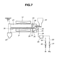
- a conductive silicon composite powder was prepared using a rotary furnace as shown in FIG. 7 .
- FIG. 7 illustrates one exemplary rotary furnace which is preferred in the practice of the invention.
- the system includes a furnace cylinder 21 for receiving a charge or silicon oxide powder P, which is inclined at an angle of 0 to 10°, especially 0.1 to 5° relative to the horizontal.
- the furnace cylinder 21 is coupled to a feeder 22 at an inlet side and a recovery hopper 23 at an outlet side. When inclined, the furnace cylinder 21 is inclined downward from the inlet side to the outlet side.
- the system further includes a mechanism 24 for rotating the furnace cylinder 21 in cooperation with a motor 25.
- the rotating mechanism 24 includes the motor 25, a pulley 27 attached to a rotating shaft 26 of the motor 25, a pulley 28 attached to the furnace cylinder 21, and a belt 29 trained therebetween, but is not limited thereto.
- the furnace cylinder 21 is rotatably supported on rollers 30, 30. Then the rotating mechanism 24 operates to rotate the furnace cylinder 21 about its axis at a predetermined speed.
- an organic gas or vapor inlet line 33 Further included in the system are an organic gas or vapor inlet line 33, an inert gas inlet line 34, flow meters 31 and 32 in the lines 33 and 34, and a gas blender 35 to which the lines 33 and 34 are connected.
- the gases are mixed in the gas blender 35, whereupon the gas mixture is fed through a feed line 36 and introduced into the furnace cylinder 21 through an inlet port.
- a heater 37 is disposed outside the furnace cylinder 21.
- SiOx silicon oxide powder SiOx
- the black powder was ground by an automated mortar for one hour, obtaining a conductive silicon composite powder.
- the conductive silicon composite powder had an average particle size of 3.2 ⁇ m, a BET specific surface area of 9.8 m 2 /g, and a carbon coverage of 18% by weight, with a peak of crystalline Si being observed on x-ray diffractometry.
- a lithium ion secondary cell was constructed.
- a charge/discharge test was carried out as in Example 6.
- the cell had as high a capacity as demonstrated by a first cycle discharge capacity of 1420 mAh/cm 3 , a 50th cycle discharge capacity of 1400 mAh/cm 3 , and a cycle retentivity after 50 cycles of 98.6%. It was a lithium ion secondary cell having an improved initial charge/discharge efficiency and cycle performance.
- the conductive silicon composites of the invention afforded satisfactory cycle performance when used as the negative electrode material in a non-aqueous electrolyte secondary cell.
Landscapes
- Chemical & Material Sciences (AREA)
- Engineering & Computer Science (AREA)
- Electrochemistry (AREA)
- General Chemical & Material Sciences (AREA)
- Chemical Kinetics & Catalysis (AREA)
- Nanotechnology (AREA)
- Materials Engineering (AREA)
- Physics & Mathematics (AREA)
- Composite Materials (AREA)
- Condensed Matter Physics & Semiconductors (AREA)
- General Physics & Mathematics (AREA)
- Crystallography & Structural Chemistry (AREA)
- Manufacturing & Machinery (AREA)
- Organic Chemistry (AREA)
- Inorganic Chemistry (AREA)
- Battery Electrode And Active Subsutance (AREA)
- Secondary Cells (AREA)
Claims (15)
- Composite de silicium conducteur dans lequel des particules ayant une structure dans laquelle des cristallites de silicium, ayant chacun une taille de 1 à 500 nm, sont dispersés dans du dioxyde de silicium, sont revêtues de carbone sur leurs surfaces.
- Composite de silicium conducteur selon la revendication 1, dans lequel les particules ont une granulométrie moyenne de 0,01 à 30 µm, une aire spécifique BET de 0,5 à 20 m2/g, et une couverture de carbone de 3 à 70 % en poids.
- Composite de silicium conducteur selon la revendication 1 ou 2, dans lequel les surfaces des particules sont au moins partiellement fusionnées au carbone.
- Composite de silicium conducteur selon la revendication 1, 2 ou 3, dans lequel, lors d'une analyse par diffractométrie des rayons X, est observé un pic de diffraction attribuable à Si(111), et les cristallites de silicium ont une taille de 1 à 500 nm, telle que déterminée à partir de demi-largeur du pic de diffraction par le procédé de Scherrer, et la couverture de carbone est de 5 à 70 % en poids du composite de silicium.
- Composite de silicium conducteur selon l'une quelconque des revendications 1 à 4, qui contient 1 à 35 % en poids de silicium de valence zéro capable de générer de l'hydrogène gazeux lors d'une réaction avec une solution d'hydroxyde alcalin.
- Composite de silicium conducteur selon l'une quelconque des revendications 1 à 5, dans lequel, sur une spectroscopie Raman, le décalage Raman indique un spectre intrinsèque de structure graphitique près de 1580 cm-1.
- Procédé pour préparer un composite de l'une quelconque des revendications 1 à 6, comprenant les étapes consistant à dismuter de l'oxyde de silicium avec un gaz organique et/ou de la vapeur à une température de 900 à 1400°C et à effectuer simultanément une déposition chimique en phase vapeur.
- Procédé pour préparer un composite de silicium conducteur selon la revendication 7, dans lequel l'oxyde de silicium représenté par la formule générale SiOx, où 1 ≤ x < 1,6, est sous la forme de particules ayant une granulométrie moyenne de 0,01 à 30 µm et une aire spécifique BET de 0,1 à 30 m2/g.
- Procédé pour préparer un composite de l'une quelconque des revendications 1 à 6, comprenant l'étape consistant à effectuer une déposition chimique en phase vapeur d'un composant avec un gaz organique et/ou de la vapeur à une température de 800 à 1400°C,
le composant étant choisi parmi un composite de silicium obtenu par traitement préalable à la chaleur d'oxyde de silicium dans une atmosphère de gaz inerte à 900 à 1400°C pour une dismutation, un composite obtenu par revêtement de microparticules de silicium avec du dioxyde de silicium par le procédé sol-gel, un composite obtenu par coagulation d'une poudre fine de silicium à l'aide de silice finement divisée et d'eau et frittage, et un produit obtenu par chauffage de silicium et d'oxyde partiel ou de nitrure de celui-ci dans un courant de gaz inerte à 800 à 1400°C. - Procédé pour préparer un composite de l'une quelconque des revendications 1 à 6, comprenant les étapes consistant à soumettre au préalable de l'oxyde de silicium à une déposition chimique en phase vapeur avec un gaz organique et/ou de la vapeur à une température de 500 à 1200°C et à traiter à la chaleur le produit résultant dans une atmosphère de gaz inerte à 900 à 1400°C pour une dismutation.
- Procédé pour préparer un composite de silicium conducteur selon l'une quelconque des revendications 7 à 10, lequel procédé est effectué dans un réacteur choisi parmi un réacteur à lit fluidisé, un four rotatif, un réacteur à lit mobile vertical, un four à tunnel, un four discontinu et un séchoir rotatif.
- Matériau d'électrode négative pour une pile secondaire à électrolyte non aqueux, comprenant le composite de silicium conducteur de l'une quelconque des revendications 1 à 6.
- Matériau d'électrode négative pour une pile secondaire à électrolyte non aqueux, comprenant un mélange du composite de silicium conducteur de l'une quelconque des revendications 1 à 6 et de 1 à 60 % en poids d'un agent conducteur, le mélange ayant une teneur totale en carbone de 25 à 90 % en poids.
- Electrode négative comprenant un matériau d'électrode négative de la revendication 12 ou 13.
- Pile secondaire à électrolyte non aqueux ayant une électrode négative de la revendication 14.
Applications Claiming Priority (2)
| Application Number | Priority Date | Filing Date | Title |
|---|---|---|---|
| JP2002142777 | 2002-05-17 | ||
| JP2002142777 | 2002-05-17 |
Publications (3)
| Publication Number | Publication Date |
|---|---|
| EP1363341A2 EP1363341A2 (fr) | 2003-11-19 |
| EP1363341A3 EP1363341A3 (fr) | 2004-01-14 |
| EP1363341B1 true EP1363341B1 (fr) | 2011-04-06 |
Family
ID=29267834
Family Applications (1)
| Application Number | Title | Priority Date | Filing Date |
|---|---|---|---|
| EP02256435A Expired - Fee Related EP1363341B1 (fr) | 2002-05-17 | 2002-09-17 | Composite de silicium conducteur, sa préparation et la matière active négative pour cellule secondaire à électrolyte non aqueux |
Country Status (6)
| Country | Link |
|---|---|
| US (1) | US7037581B2 (fr) |
| EP (1) | EP1363341B1 (fr) |
| KR (1) | KR100765812B1 (fr) |
| CN (1) | CN1302075C (fr) |
| DE (1) | DE60239668D1 (fr) |
| TW (1) | TWI278429B (fr) |
Families Citing this family (176)
| Publication number | Priority date | Publication date | Assignee | Title |
|---|---|---|---|---|
| JP2004119176A (ja) * | 2002-09-26 | 2004-04-15 | Toshiba Corp | 非水電解質二次電池用負極活物質及び非水電解質二次電池 |
| EP1604415B1 (fr) * | 2003-03-26 | 2012-11-21 | Canon Kabushiki Kaisha | Matériau d'électrode pour batterie secondaire au lithium et structure d'électrode comportant ledit matériau |
| KR100595896B1 (ko) * | 2003-07-29 | 2006-07-03 | 주식회사 엘지화학 | 리튬 이차 전지용 음극 활물질 및 그의 제조 방법 |
| JP4171904B2 (ja) * | 2003-08-05 | 2008-10-29 | 信越化学工業株式会社 | リチウムイオン二次電池負極材及びその製造方法 |
| JP4159954B2 (ja) * | 2003-09-24 | 2008-10-01 | 株式会社東芝 | 非水電解質電池 |
| CN100547830C (zh) * | 2004-03-08 | 2009-10-07 | 三星Sdi株式会社 | 可充电锂电池的负极活性物质及其制法以及包含它的可充电锂电池 |
| US7790316B2 (en) * | 2004-03-26 | 2010-09-07 | Shin-Etsu Chemical Co., Ltd. | Silicon composite particles, preparation thereof, and negative electrode material for non-aqueous electrolyte secondary cell |
| JP4450192B2 (ja) * | 2004-07-01 | 2010-04-14 | 信越化学工業株式会社 | 珪素複合体及びその製造方法並びに非水電解質二次電池用負極材 |
| CN100553016C (zh) * | 2004-08-26 | 2009-10-21 | 松下电器产业株式会社 | 电极用复合粒子及其制造方法以及二次电池 |
| JP4739781B2 (ja) * | 2005-03-11 | 2011-08-03 | 三洋電機株式会社 | リチウム二次電池 |
| JP4193141B2 (ja) * | 2005-03-25 | 2008-12-10 | ソニー株式会社 | リチウム二次電池用負極およびリチウム二次電池、並びにそれらの製造方法 |
| US8119287B2 (en) * | 2005-05-16 | 2012-02-21 | Mitsubishi Chemical Corporation | Nonaqueous electrolyte rechargeable battery, and negative electrode and material thereof |
| US7749406B2 (en) * | 2005-08-11 | 2010-07-06 | Stevenson David E | SiOx:Si sputtering targets and method of making and using such targets |
| US7658822B2 (en) * | 2005-08-11 | 2010-02-09 | Wintek Electro-Optics Corporation | SiOx:Si composite articles and methods of making same |
| US7790060B2 (en) * | 2005-08-11 | 2010-09-07 | Wintek Electro Optics Corporation | SiOx:Si composite material compositions and methods of making same |
| JP5036161B2 (ja) * | 2005-10-14 | 2012-09-26 | パナソニック株式会社 | リチウムイオン二次電池用負極活物質、その製造方法、およびそれを用いたリチウムイオン二次電池 |
| US8216719B2 (en) | 2006-02-13 | 2012-07-10 | Hitachi Maxell Energy, Ltd. | Non-aqueous secondary battery and method for producing the same |
| US7776473B2 (en) | 2006-03-27 | 2010-08-17 | Shin-Etsu Chemical Co., Ltd. | Silicon-silicon oxide-lithium composite, making method, and non-aqueous electrolyte secondary cell negative electrode material |
| WO2007114168A1 (fr) * | 2006-03-30 | 2007-10-11 | Sanyo Electric Co., Ltd. | Batterie au lithium rechargeable et son procede de fabrication |
| US20080057385A1 (en) * | 2006-08-30 | 2008-03-06 | Shin-Etsu Chemical Co., Ltd. | Separator for non-aqueous secondary battery, making method, and non-aqueous electrolyte secondary battery |
| JP4321584B2 (ja) * | 2006-12-18 | 2009-08-26 | ソニー株式会社 | 二次電池用負極および二次電池 |
| KR100851969B1 (ko) * | 2007-01-05 | 2008-08-12 | 삼성에스디아이 주식회사 | 음극 활물질, 그 제조 방법 및 이를 채용한 음극과 리튬전지 |
| KR101451801B1 (ko) * | 2007-02-14 | 2014-10-17 | 삼성에스디아이 주식회사 | 음극 활물질, 그 제조 방법 및 이를 채용한 음극과 리튬전지 |
| JP5251024B2 (ja) * | 2007-07-26 | 2013-07-31 | ソニー株式会社 | リチウムイオン二次電池用負極およびリチウムイオン二次電池 |
| JP5143700B2 (ja) * | 2007-10-24 | 2013-02-13 | パナソニック株式会社 | 電気化学素子用電極およびそれを用いた電気化学素子 |
| KR100898293B1 (ko) * | 2007-11-27 | 2009-05-18 | 삼성에스디아이 주식회사 | 리튬 이차 전지용 음극 활물질 및 이의 제조 방법 |
| JP5196149B2 (ja) * | 2008-02-07 | 2013-05-15 | 信越化学工業株式会社 | 非水電解質二次電池用負極材及びその製造方法並びにリチウムイオン二次電池及び電気化学キャパシタ |
| US10727481B2 (en) | 2009-02-25 | 2020-07-28 | Cf Traverse Llc | Energy storage devices |
| JP4844764B2 (ja) * | 2008-03-17 | 2011-12-28 | 信越化学工業株式会社 | 非水電解質二次電池負極及びそれを用いた非水電解質二次電池 |
| US8105718B2 (en) | 2008-03-17 | 2012-01-31 | Shin-Etsu Chemical Co., Ltd. | Non-aqueous electrolyte secondary battery, negative electrode material, and making method |
| JP5245559B2 (ja) * | 2008-06-16 | 2013-07-24 | 信越化学工業株式会社 | 非水電解質二次電池用負極材及びその製造方法、ならびにリチウムイオン二次電池及び電気化学キャパシタ |
| JP5245592B2 (ja) * | 2008-07-14 | 2013-07-24 | 信越化学工業株式会社 | 非水電解質二次電池用負極材、ならびにリチウムイオン二次電池及び電気化学キャパシタ |
| JP4883323B2 (ja) * | 2008-08-26 | 2012-02-22 | 信越化学工業株式会社 | 非水電解質二次電池負極材及びSi−O−Al複合体の製造方法、ならびに非水電解質二次電池負極及び非水電解質二次電池 |
| WO2010050507A1 (fr) * | 2008-10-31 | 2010-05-06 | 日立マクセル株式会社 | Batterie secondaire non aqueuse |
| US8580432B2 (en) | 2008-12-04 | 2013-11-12 | Nanotek Instruments, Inc. | Nano graphene reinforced nanocomposite particles for lithium battery electrodes |
| US9093693B2 (en) | 2009-01-13 | 2015-07-28 | Samsung Electronics Co., Ltd. | Process for producing nano graphene reinforced composite particles for lithium battery electrodes |
| JP2010225494A (ja) * | 2009-03-25 | 2010-10-07 | Shin-Etsu Chemical Co Ltd | 非水電解質二次電池用負極材及びその製造方法、ならびにリチウムイオン二次電池 |
| JP4634515B2 (ja) * | 2009-06-19 | 2011-02-16 | 株式会社大阪チタニウムテクノロジーズ | 珪素酸化物およびリチウムイオン二次電池用負極材 |
| US20110020701A1 (en) * | 2009-07-16 | 2011-01-27 | Carbon Micro Battery Corporation | Carbon electrode structures for batteries |
| JP5554780B2 (ja) * | 2009-09-01 | 2014-07-23 | 日立ビークルエナジー株式会社 | 非水電解質二次電池 |
| JP4769319B2 (ja) | 2009-09-10 | 2011-09-07 | 株式会社大阪チタニウムテクノロジーズ | 珪素酸化物およびリチウムイオン二次電池用負極材 |
| JP5704633B2 (ja) * | 2009-09-29 | 2015-04-22 | Necエナジーデバイス株式会社 | 二次電池 |
| JP5748193B2 (ja) * | 2009-09-29 | 2015-07-15 | Necエナジーデバイス株式会社 | 二次電池 |
| KR101084077B1 (ko) * | 2009-10-14 | 2011-11-16 | 삼성에스디아이 주식회사 | 리튬이차전지용 음극활물질, 그의 제조방법 및 그를 포함하는 리튬이차전지 |
| JP5215978B2 (ja) * | 2009-10-28 | 2013-06-19 | 信越化学工業株式会社 | 非水電解質二次電池用負極材及びその製造方法並びにリチウムイオン二次電池 |
| WO2011056847A2 (fr) | 2009-11-03 | 2011-05-12 | Envia Systems, Inc. | Matières d'anode à grande capacité pour batteries au lithium-ion |
| KR101073017B1 (ko) * | 2010-01-05 | 2011-10-12 | 삼성에스디아이 주식회사 | 리튬 이차 전지용 음극 및 이를 포함하는 리튬 이차 전지 |
| US11380890B2 (en) | 2010-01-18 | 2022-07-05 | Enevate Corporation | Surface modification of silicon particles for electrochemical storage |
| US9553303B2 (en) | 2010-01-18 | 2017-01-24 | Enevate Corporation | Silicon particles for battery electrodes |
| US20170040598A1 (en) | 2015-08-07 | 2017-02-09 | Enevate Corporation | Surface modification of silicon particles for electrochemical storage |
| US10461366B1 (en) | 2010-01-18 | 2019-10-29 | Enevate Corporation | Electrolyte compositions for batteries |
| KR102098547B1 (ko) * | 2010-01-18 | 2020-04-08 | 에네베이트 코포레이션 | 전기화학적 축전지용 복합재 박막 |
| US20120321940A1 (en) * | 2010-03-26 | 2012-12-20 | Daisuke Kawasaki | Nonaqueous electrolyte secondary battery |
| JP5411780B2 (ja) | 2010-04-05 | 2014-02-12 | 信越化学工業株式会社 | 非水電解質二次電池用負極材及び非水電解質二次電池用負極材の製造方法並びにリチウムイオン二次電池 |
| JP5411781B2 (ja) | 2010-04-05 | 2014-02-12 | 信越化学工業株式会社 | 非水電解質二次電池用負極材及び非水電解質二次電池用負極材の製造方法並びにリチウムイオン二次電池 |
| US9876221B2 (en) * | 2010-05-14 | 2018-01-23 | Samsung Sdi Co., Ltd. | Negative active material for rechargeable lithium battery and rechargeable lithium battery including same |
| CN103003986A (zh) * | 2010-07-20 | 2013-03-27 | 株式会社大阪钛技术 | 锂离子二次电池负极材料用粉末、锂离子二次电池负极及电容器负极、以及锂离子二次电池及电容器 |
| KR101513819B1 (ko) * | 2010-08-25 | 2015-04-20 | 오사카 티타늄 테크놀로지스 캄파니 리미티드 | 리튬 이온 2차 전지 음극재용 분말, 이를 이용한 리튬 이온 2차 전지 음극 및 캐패시터 음극, 및 리튬 이온 2차 전지 및 캐패시터 |
| WO2012029387A1 (fr) * | 2010-09-02 | 2012-03-08 | 日本電気株式会社 | Batterie secondaire |
| JP6024457B2 (ja) * | 2010-09-02 | 2016-11-16 | 日本電気株式会社 | 二次電池およびそれに用いる二次電池用電解液 |
| WO2012029653A1 (fr) * | 2010-09-02 | 2012-03-08 | 日本電気株式会社 | Batterie rechargeable |
| WO2012029386A1 (fr) * | 2010-09-02 | 2012-03-08 | 日本電気株式会社 | Batterie secondaire |
| WO2012036127A1 (fr) | 2010-09-14 | 2012-03-22 | 日立マクセルエナジー株式会社 | Pile secondaire non aqueuse |
| JPWO2012049889A1 (ja) * | 2010-10-14 | 2014-02-24 | 日本電気株式会社 | 二次電池およびそれに用いる二次電池用電解液 |
| JP5476273B2 (ja) * | 2010-10-27 | 2014-04-23 | 信越化学工業株式会社 | 非水電解液二次電池 |
| JPWO2012056765A1 (ja) | 2010-10-29 | 2014-03-20 | 日本電気株式会社 | 二次電池及びその製造方法 |
| KR101191625B1 (ko) | 2010-12-01 | 2012-10-17 | 삼성에스디아이 주식회사 | 리튬 이차 전지용 음극 활물질을 포함하는 리튬 이차 전지 |
| US9345069B2 (en) | 2010-12-03 | 2016-05-17 | Wood Stone Ideas, Llc | Heat generation and exchange devices incorporating a mixture of conductive and dielectric particles |
| KR101367393B1 (ko) | 2010-12-20 | 2014-02-24 | 히다치 막셀 가부시키가이샤 | 비수 2차 전지 |
| US10388943B2 (en) | 2010-12-22 | 2019-08-20 | Enevate Corporation | Methods of reducing occurrences of short circuits and/or lithium plating in batteries |
| US9397338B2 (en) | 2010-12-22 | 2016-07-19 | Enevate Corporation | Electrodes, electrochemical cells, and methods of forming electrodes and electrochemical cells |
| US9583757B2 (en) | 2010-12-22 | 2017-02-28 | Enevate Corporation | Electrodes, electrochemical cells, and methods of forming electrodes and electrochemical cells |
| WO2012108113A1 (fr) * | 2011-02-09 | 2012-08-16 | 株式会社大阪チタニウムテクノロジーズ | Poudre pour matériau d'électrode négative d'accumulateur lithium-ion, électrode négative d'accumulateur lithium-ion et électrode négative de condensateur l'utilisant, accumulateur lithium-ion, et condensateur |
| US9601228B2 (en) | 2011-05-16 | 2017-03-21 | Envia Systems, Inc. | Silicon oxide based high capacity anode materials for lithium ion batteries |
| JP5935246B2 (ja) * | 2011-06-24 | 2016-06-15 | ソニー株式会社 | リチウムイオン二次電池、リチウムイオン二次電池用負極、電池パック、電動車両、電力貯蔵システム、電動工具および電子機器 |
| GB2492167C (en) | 2011-06-24 | 2018-12-05 | Nexeon Ltd | Structured particles |
| KR20130024383A (ko) * | 2011-08-31 | 2013-03-08 | 삼성에스디아이 주식회사 | 리튬 이차 전지용 음극 활물질 및 이를 포함하는 리튬 이차 전지 |
| JP5636351B2 (ja) | 2011-09-27 | 2014-12-03 | 株式会社東芝 | 非水電解質二次電池用負極活物質、非水電解質二次電池、電池パック及び非水電解質二次電池用負極活物質の製造方法 |
| KR101772113B1 (ko) | 2011-11-08 | 2017-08-29 | 삼성에스디아이 주식회사 | 음극 활물질, 그 제조방법, 이를 포함하는 전극 및 이를 채용한 리튬 전지 |
| JP5982811B2 (ja) * | 2011-12-20 | 2016-08-31 | ソニー株式会社 | 二次電池用活物質、二次電池および電子機器 |
| KR101733736B1 (ko) * | 2012-01-06 | 2017-05-10 | 삼성에스디아이 주식회사 | 리튬 이차 전지용 음극 활물질, 그 제조 방법 및 이를 포함하는 리튬 이차 전지 |
| US9139441B2 (en) | 2012-01-19 | 2015-09-22 | Envia Systems, Inc. | Porous silicon based anode material formed using metal reduction |
| KR101718055B1 (ko) | 2012-02-13 | 2017-03-20 | 삼성에스디아이 주식회사 | 음극 활물질 및 이를 포함하는 리튬 전지 |
| JP5459448B1 (ja) | 2012-03-02 | 2014-04-02 | 日本電気株式会社 | 二次電池 |
| WO2013145108A1 (fr) | 2012-03-26 | 2013-10-03 | 株式会社 東芝 | Matériau actif d'électrode négative pour batteries rechargeables à électrolyte non aqueux, batterie rechargeable à électrolyte non aqueux, bloc de batteries et procédé permettant de fabriquer un matériau actif d'électrode négative pour batteries rechargeables à électrolyte non aqueux |
| JP5621868B2 (ja) * | 2012-03-27 | 2014-11-12 | Tdk株式会社 | リチウムイオン二次電池 |
| US9512523B2 (en) | 2012-04-19 | 2016-12-06 | Lg Chem, Ltd. | Porous electrode active material and secondary battery including the same |
| JP5686441B2 (ja) | 2012-04-19 | 2015-03-18 | エルジー・ケム・リミテッド | ケイ素系正極活物質及びこれを含む二次電池 |
| US9780358B2 (en) | 2012-05-04 | 2017-10-03 | Zenlabs Energy, Inc. | Battery designs with high capacity anode materials and cathode materials |
| US10553871B2 (en) | 2012-05-04 | 2020-02-04 | Zenlabs Energy, Inc. | Battery cell engineering and design to reach high energy |
| WO2013191080A1 (fr) | 2012-06-18 | 2013-12-27 | Jsr株式会社 | Composition de liant pour électrodes de dispositif accumulateur d'électricité, pâte pour électrodes de dispositif accumulateur d'électricité, électrode de dispositif accumulateur d'électricité et dispositif accumulateur d'électricité |
| JP5440661B2 (ja) | 2012-06-27 | 2014-03-12 | 株式会社豊田自動織機 | 珪素含有材料および珪素含有材料を含む二次電池用活物質 |
| CA2872650A1 (fr) | 2012-07-06 | 2014-01-09 | Toray Industries, Inc. | Materiau d'electrode negative pour batteries secondaires a ion lithium, materiau d'electrode negative composite pour batteries secondaires a ion lithium, composition de resine pour electrodes negatives de batteries secondaires a ion lithium, electrode negative de batteries secondaires a ion lithium, et batterie secondaire a ion lithium |
| KR101578262B1 (ko) | 2012-07-24 | 2015-12-28 | 주식회사 엘지화학 | 다공성 규소계 전극 활물질 및 이를 포함하는 이차전지 |
| KR101634843B1 (ko) | 2012-07-26 | 2016-06-29 | 주식회사 엘지화학 | 이차전지용 전극 활물질 |
| EP2693533B1 (fr) * | 2012-08-03 | 2018-06-13 | LG Chem, Ltd. | Matériau actif d'électrode pour batterie secondaire |
| EP2913872B1 (fr) | 2012-10-26 | 2020-07-15 | Hitachi Chemical Company, Ltd. | Matériau d'électrode négative pour batterie secondaire au lithium-ion, électrode négative pour batterie secondaire au lithium-ion, et batterie secondaire au lithium-ion |
| TWI624984B (zh) * | 2012-10-26 | 2018-05-21 | 日立化成股份有限公司 | 鋰離子二次電池用負極材料、鋰離子二次電池用負極及鋰離子二次電池 |
| KR101610995B1 (ko) | 2012-11-30 | 2016-04-08 | 주식회사 엘지화학 | 규소계 복합체 및 이의 제조방법 |
| WO2014088270A1 (fr) * | 2012-12-06 | 2014-06-12 | 주식회사 엘지화학 | Matériau actif d'anode à haute capacité pour batterie secondaire au lithium, procédé de fabrication associé, et batterie secondaire au lithium comprenant ledit matériau actif d'anode à haute capacité |
| KR101698763B1 (ko) | 2012-12-10 | 2017-01-23 | 삼성에스디아이 주식회사 | 음극 활물질, 그 제조방법, 이를 포함하는 전극 및 이를 채용한 리튬 이차 전지 |
| JP6316207B2 (ja) | 2012-12-12 | 2018-04-25 | エルジー・ケム・リミテッド | 二次電池用電極、それを含む二次電池及びケーブル型二次電池 |
| JP5912190B2 (ja) * | 2012-12-12 | 2016-04-27 | エルジー・ケム・リミテッド | 二次電池用電極、それを含む二次電池及びケーブル型二次電池 |
| WO2014095811A1 (fr) * | 2012-12-20 | 2014-06-26 | Umicore | Matière d'électrode négative pour batterie rechargeable et son procédé de production |
| JP6058704B2 (ja) * | 2013-01-30 | 2017-01-11 | 三洋電機株式会社 | 非水電解質二次電池用負極活物質、当該負極活物質を用いた非水電解質二次電池用負極、及び当該負極を用いた非水電解質二次電池 |
| JP5796587B2 (ja) * | 2013-02-22 | 2015-10-21 | 株式会社豊田自動織機 | 負極活物質、非水電解質二次電池用負極ならびに非水電解質二次電池 |
| TWI504037B (zh) | 2013-03-11 | 2015-10-11 | Hitachi Maxell | Lithium secondary battery pack, and the use of this electronic machine, charging system and charging method |
| WO2014158729A1 (fr) * | 2013-03-13 | 2014-10-02 | Enevate Corporation | Particules de silicium pour électrodes de batterie |
| DE102013204799A1 (de) | 2013-03-19 | 2014-09-25 | Wacker Chemie Ag | Si/C-Komposite als Anodenmaterialien für Lithium-Ionen-Batterien |
| JP5827261B2 (ja) * | 2013-03-28 | 2015-12-02 | 信越化学工業株式会社 | 珪素含有粒子、非水電解質二次電池の負極材、および、非水電解質二次電池 |
| CN104620426B (zh) * | 2013-03-29 | 2018-03-02 | 三洋电机株式会社 | 非水电解质二次电池用负极活性物质以及非水电解质二次电池 |
| US10020491B2 (en) * | 2013-04-16 | 2018-07-10 | Zenlabs Energy, Inc. | Silicon-based active materials for lithium ion batteries and synthesis with solution processing |
| KR101723186B1 (ko) * | 2013-05-07 | 2017-04-05 | 주식회사 엘지화학 | 리튬 이차 전지용 음극 활물질, 이의 제조 방법 및 이를 포함하는 리튬 이차 전지 |
| WO2014188851A1 (fr) | 2013-05-23 | 2014-11-27 | 信越化学工業株式会社 | Matériau d'électrode négative pour batteries secondaires à électrolyte non aqueux, et batterie secondaire |
| US10886526B2 (en) | 2013-06-13 | 2021-01-05 | Zenlabs Energy, Inc. | Silicon-silicon oxide-carbon composites for lithium battery electrodes and methods for forming the composites |
| CN105409047B (zh) * | 2013-07-31 | 2019-03-19 | 株式会社Adeka | 锂二次电池及锂二次电池用电解液 |
| JP6508870B2 (ja) | 2013-08-14 | 2019-05-08 | 東ソー株式会社 | リチウム二次電池用複合活物質およびその製造方法 |
| US11476494B2 (en) | 2013-08-16 | 2022-10-18 | Zenlabs Energy, Inc. | Lithium ion batteries with high capacity anode active material and good cycling for consumer electronics |
| JP2015072809A (ja) * | 2013-10-03 | 2015-04-16 | 信越化学工業株式会社 | 珪素含有材料並びに非水電解質二次電池用負極及び非水電解質二次電池並びにそれらの製造方法 |
| TWI627785B (zh) * | 2013-10-31 | 2018-06-21 | Lg化學股份有限公司 | 用於鋰二次電池之陽極活性材料及其製備方法 |
| WO2015080203A1 (fr) * | 2013-11-27 | 2015-06-04 | 三菱化学株式会社 | Matière carbonée pour électrode négative de batterie rechargeable non aqueuse, électrode négative pour batterie rechargeable non aqueuse et batterie rechargeable non aqueuse |
| CA2835583A1 (fr) | 2013-11-28 | 2015-05-28 | Hydro-Quebec | Methode de preparation de siox nano-structure, et son utilisation comme anode de batterie lithium-ion |
| US10205164B2 (en) * | 2013-12-03 | 2019-02-12 | Lg Chem Ltd. | Porous silicon-based anode active material, method for preparing the same, and lithium secondary battery comprising the same |
| KR102237829B1 (ko) | 2013-12-30 | 2021-04-08 | 삼성전자주식회사 | 리튬 이차 전지용 음극재, 그 제조방법, 이를 음극으로 포함하는 리튬 이차 전지 |
| JP6517703B2 (ja) | 2014-01-24 | 2019-05-22 | マクセルホールディングス株式会社 | 非水二次電池 |
| DE102014202156A1 (de) | 2014-02-06 | 2015-08-06 | Wacker Chemie Ag | Si/G/C-Komposite für Lithium-Ionen-Batterien |
| JP6416214B2 (ja) | 2014-03-17 | 2018-10-31 | 株式会社東芝 | 非水電解質二次電池用活物質、非水電解質二次電池用電極、非水電解質二次電池、電池パックおよび非水電解質二次電池用活物質の製造方法 |
| KR101567203B1 (ko) | 2014-04-09 | 2015-11-09 | (주)오렌지파워 | 이차 전지용 음극 활물질 및 이의 방법 |
| JP6196183B2 (ja) * | 2014-04-22 | 2017-09-13 | 信越化学工業株式会社 | 非水電解質二次電池用負極材及びその製造方法、並びに非水電解質二次電池用負極活物質層、非水電解質二次電池用負極、非水電解質二次電池 |
| KR101604352B1 (ko) | 2014-04-22 | 2016-03-18 | (주)오렌지파워 | 음극 활물질 및 이를 포함하는 리튬 이차 전지 |
| KR102276423B1 (ko) * | 2014-06-10 | 2021-07-12 | 삼성전자주식회사 | 복합체, 이를 이용한 전기화학적 활물질 복합체, 이를 포함한 전극, 리튬 전지, 전계 방출 소자, 바이오센서, 반도체 소자 및 열전소자 |
| CN104022257B (zh) * | 2014-06-16 | 2019-02-12 | 深圳市贝特瑞新能源材料股份有限公司 | 一种锂离子电池氧化亚硅复合负极材料、制备方法及其用途 |
| JP6268049B2 (ja) * | 2014-06-23 | 2018-01-24 | 信越化学工業株式会社 | 非水電解質二次電池用負極材及び非水電解質二次電池並びに負極活物質粒子の製造方法 |
| WO2016009590A1 (fr) * | 2014-07-15 | 2016-01-21 | 信越化学工業株式会社 | Matière d'électrode négative pour batterie secondaire à électrolyte non aqueux et procédé de production de particule de matière active d'électrode négative |
| KR101550781B1 (ko) | 2014-07-23 | 2015-09-08 | (주)오렌지파워 | 2 차 전지용 실리콘계 활물질 입자의 제조 방법 |
| CN106604890B (zh) | 2014-08-27 | 2019-08-06 | 株式会社丰田自动织机 | 碳被覆硅材料的制造方法 |
| JP6477713B2 (ja) * | 2014-09-01 | 2019-03-06 | 三洋電機株式会社 | 非水電解質二次電池用負極活物質 |
| WO2016053031A1 (fr) * | 2014-10-02 | 2016-04-07 | 주식회사 엘지화학 | Matériau actif d'anode pour batterie secondaire au lithium, son procédé de fabrication, et batterie secondaire au lithium le comprenant |
| KR101763478B1 (ko) * | 2014-10-02 | 2017-07-31 | 주식회사 엘지화학 | 리튬 이차전지용 음극활물질, 이의 제조방법, 및 이를 포함하는 리튬 이차전지 |
| JP6312211B2 (ja) * | 2014-10-08 | 2018-04-18 | 信越化学工業株式会社 | 非水電解質二次電池用負極活物質、非水電解質二次電池用負極、非水電解質二次電池、及び非水電解質二次電池用負極材の製造方法 |
| KR101888230B1 (ko) * | 2014-11-27 | 2018-08-13 | 주식회사 엘지화학 | 규소계 음극활물질 및 이의 제조방법 |
| JP6438287B2 (ja) | 2014-12-05 | 2018-12-12 | 株式会社東芝 | 非水電解質電池用活物質、非水電解質電池用電極、非水電解質二次電池および電池パック |
| WO2016091957A1 (fr) | 2014-12-10 | 2016-06-16 | Basf Se | Procédé permettant de produire une électrode contenant des particules de silicium recouvertes de carbone |
| GB2533161C (en) | 2014-12-12 | 2019-07-24 | Nexeon Ltd | Electrodes for metal-ion batteries |
| KR101614016B1 (ko) | 2014-12-31 | 2016-04-20 | (주)오렌지파워 | 실리콘계 음극 활물질 및 이의 제조 방법 |
| JP2016152077A (ja) * | 2015-02-16 | 2016-08-22 | 信越化学工業株式会社 | 非水電解質二次電池用負極活物質及び非水電解質二次電池、並びに非水電解質二次電池用負極材の製造方法 |
| JP6448525B2 (ja) * | 2015-02-26 | 2019-01-09 | 信越化学工業株式会社 | 非水電解質二次電池用負極活物質、非水電解質二次電池用負極、及び非水電解質二次電池、並びに非水電解質二次電池用負極材の製造方法 |
| US10446837B2 (en) * | 2015-02-26 | 2019-10-15 | Shin-Etsu Chemical Co., Ltd. | Negative electrode active material for non-aqueous electrolyte secondary battery, negative electrode for non-aqueous electrolyte secondary battery, non-aqueous electrolyte secondary battery, and method of producing negative electrode material for a non-aqueous electrolyte secondary battery |
| KR101726037B1 (ko) * | 2015-03-26 | 2017-04-11 | (주)오렌지파워 | 실리콘계 음극 활물질 및 이의 제조 방법 |
| JP6428941B2 (ja) * | 2015-07-31 | 2018-11-28 | 信越化学工業株式会社 | リチウムイオン二次電池用負極材、その製造方法及びリチウムイオン二次電池 |
| KR101971498B1 (ko) * | 2015-09-24 | 2019-04-23 | 주식회사 엘지화학 | 리튬 이차전지용 음극활물질 및 그 제조방법 |
| JP6445956B2 (ja) * | 2015-11-17 | 2018-12-26 | 信越化学工業株式会社 | 負極活物質、混合負極活物質材料、非水電解質二次電池用負極、リチウムイオン二次電池 |
| JP6507106B2 (ja) * | 2016-01-07 | 2019-04-24 | 信越化学工業株式会社 | 負極活物質、混合負極活物質材料、非水電解質二次電池用負極、リチウムイオン二次電池、負極活物質の製造方法、及びリチウムイオン二次電池の製造方法 |
| CN115863618A (zh) | 2016-11-22 | 2023-03-28 | 三菱化学株式会社 | 非水二次电池用负极材料、非水二次电池用负极及非水二次电池 |
| JP6634398B2 (ja) * | 2017-03-13 | 2020-01-22 | 信越化学工業株式会社 | 負極活物質、混合負極活物質材料、及び負極活物質の製造方法 |
| WO2018179111A1 (fr) * | 2017-03-28 | 2018-10-04 | 日立化成株式会社 | Matériau actif d'électrode négative pour batterie secondaire lithium-ion, électrode négative pour batterie secondaire lithium-ion, et batterie secondaire lithium-ion |
| KR102307911B1 (ko) | 2017-04-27 | 2021-10-01 | 삼성에스디아이 주식회사 | 리튬이차전지용 음극 활물질 및 이를 포함하는 음극을 구비한 리튬이차전지 |
| US11404686B2 (en) * | 2017-04-28 | 2022-08-02 | Sekisui Chemical Co., Ltd. | Negative electrode active material for lithium ion battery |
| GB2563455B (en) | 2017-06-16 | 2019-06-19 | Nexeon Ltd | Particulate electroactive materials for use in metal-ion batteries |
| GB201803983D0 (en) | 2017-09-13 | 2018-04-25 | Unifrax I Llc | Materials |
| US11133498B2 (en) | 2017-12-07 | 2021-09-28 | Enevate Corporation | Binding agents for electrochemically active materials and methods of forming the same |
| WO2019112643A1 (fr) | 2017-12-07 | 2019-06-13 | Enevate Corporation | Composite comprenant des particules de carbure de silicium et de carbone |
| US10686214B2 (en) | 2017-12-07 | 2020-06-16 | Enevate Corporation | Sandwich electrodes and methods of making the same |
| US11094925B2 (en) | 2017-12-22 | 2021-08-17 | Zenlabs Energy, Inc. | Electrodes with silicon oxide active materials for lithium ion cells achieving high capacity, high energy density and long cycle life performance |
| KR102207529B1 (ko) * | 2018-03-14 | 2021-01-26 | 주식회사 엘지화학 | 비정질 실리콘-탄소 복합체, 이의 제조방법 및 이를 포함하는 리튬 이차전지 |
| US11978896B2 (en) | 2018-08-30 | 2024-05-07 | Panasonic Intellectual Property Management Co., Ltd. | Negative electrode active material for nonaqueous electrolyte secondary batteries, negative electrode for nonaqueous electrolyte secondary batteries, and nonaqueous electrolyte secondary battery |
| CN110970600B (zh) * | 2018-09-28 | 2023-06-30 | 贝特瑞新材料集团股份有限公司 | 一种锂离子二次电池负极材料及其制备方法和应用 |
| CN109802120A (zh) * | 2019-01-24 | 2019-05-24 | 广东凯金新能源科技股份有限公司 | 一种硅碳复合材料及其制法 |
| EP3973584A4 (fr) | 2019-05-20 | 2023-09-20 | Nanograf Corporation | Matériau actif d'anode comprenant du carbone turbostratique à faible défaut |
| WO2021102847A1 (fr) * | 2019-11-28 | 2021-06-03 | 宁德新能源科技有限公司 | Matériau d'électrode négative, dispositif électrochimique comprenant celui-ci, et dispositif électronique |
| CN113130858B (zh) * | 2019-12-31 | 2022-12-30 | 华为技术有限公司 | 硅基负极材料及其制备方法、电池和终端 |
| CN112310372B (zh) * | 2020-10-26 | 2022-05-24 | 深圳市德方纳米科技股份有限公司 | 硅基负极材料和锂离子电池 |
| WO2022216460A1 (fr) | 2021-04-08 | 2022-10-13 | Fmc Lithium Usa Corp. | Procédé par voie sèche pour former une électrode |
| US20230102190A1 (en) * | 2021-09-29 | 2023-03-30 | GM Global Technology Operations LLC | Negative electroactive materials and methods of forming the same |
| WO2023076011A1 (fr) | 2021-10-29 | 2023-05-04 | Livent USA Corp. | Traitement à sec de formation d'électrode |
| US20230163309A1 (en) | 2021-11-22 | 2023-05-25 | Enevate Corporation | Silicon based lithium ion battery and improved cycle life of same |
Family Cites Families (13)
| Publication number | Priority date | Publication date | Assignee | Title |
|---|---|---|---|---|
| JP3008228B2 (ja) | 1991-12-18 | 2000-02-14 | セイコーインスツルメンツ株式会社 | 非水電解質二次電池及びその負極活物質の製造方法 |
| US5478671A (en) | 1992-04-24 | 1995-12-26 | Fuji Photo Film Co., Ltd. | Nonaqueous secondary battery |
| JP3242751B2 (ja) | 1992-04-24 | 2001-12-25 | 富士写真フイルム株式会社 | 非水二次電池 |
| CA2113422C (fr) * | 1992-05-14 | 1999-09-14 | Michihiro Fujiwara | Appareil de raclage des boues |
| JP2997741B2 (ja) * | 1992-07-29 | 2000-01-11 | セイコーインスツルメンツ株式会社 | 非水電解質二次電池及びその製造方法 |
| JP3846661B2 (ja) | 1997-02-24 | 2006-11-15 | 日立マクセル株式会社 | リチウム二次電池 |
| JP3918311B2 (ja) | 1997-07-29 | 2007-05-23 | ソニー株式会社 | 負極材料及びこれを用いた非水電解液二次電池 |
| US6066414A (en) * | 1997-07-29 | 2000-05-23 | Sony Corporation | Material of negative electrode and nonaqueous-electrolyte secondary battery using the same |
| JP4393610B2 (ja) * | 1999-01-26 | 2010-01-06 | 日本コークス工業株式会社 | リチウム二次電池用負極材料、リチウム二次電池、及び同二次電池の充電方法 |
| JP2000243396A (ja) | 1999-02-23 | 2000-09-08 | Hitachi Ltd | リチウム二次電池とその製造方法及びその負極材並びに電気機器 |
| JP2002042806A (ja) * | 2000-07-19 | 2002-02-08 | Japan Storage Battery Co Ltd | 非水電解質二次電池 |
| US6733922B2 (en) * | 2001-03-02 | 2004-05-11 | Samsung Sdi Co., Ltd. | Carbonaceous material and lithium secondary batteries comprising same |
| JP4308446B2 (ja) * | 2001-03-02 | 2009-08-05 | 三星エスディアイ株式会社 | 炭素質材料及びリチウム二次電池 |
-
2002
- 2002-09-13 TW TW091121032A patent/TWI278429B/zh not_active IP Right Cessation
- 2002-09-16 KR KR1020020056171A patent/KR100765812B1/ko active IP Right Grant
- 2002-09-17 DE DE60239668T patent/DE60239668D1/de not_active Expired - Lifetime
- 2002-09-17 EP EP02256435A patent/EP1363341B1/fr not_active Expired - Fee Related
- 2002-09-19 US US10/246,426 patent/US7037581B2/en not_active Expired - Lifetime
- 2002-09-20 CN CNB021558140A patent/CN1302075C/zh not_active Expired - Lifetime
Also Published As
| Publication number | Publication date |
|---|---|
| KR100765812B1 (ko) | 2007-10-10 |
| DE60239668D1 (de) | 2011-05-19 |
| CN1302075C (zh) | 2007-02-28 |
| KR20030075132A (ko) | 2003-09-22 |
| EP1363341A3 (fr) | 2004-01-14 |
| TWI278429B (en) | 2007-04-11 |
| US20030215711A1 (en) | 2003-11-20 |
| US7037581B2 (en) | 2006-05-02 |
| CN1513922A (zh) | 2004-07-21 |
| EP1363341A2 (fr) | 2003-11-19 |
Similar Documents
| Publication | Publication Date | Title |
|---|---|---|
| EP1363341B1 (fr) | Composite de silicium conducteur, sa préparation et la matière active négative pour cellule secondaire à électrolyte non aqueux | |
| JP3952180B2 (ja) | 導電性珪素複合体及びその製造方法並びに非水電解質二次電池用負極材 | |
| US10700348B2 (en) | Negative electrode material for nonaqueous electrolyte secondary batteries, and secondary battery | |
| EP1323783B1 (fr) | Poudre conductrice d'oxyde de silicium, sa préparation et matière d'électrode négative pour pile secondaire à électrolyte non-aqueux | |
| EP2088221B1 (fr) | Matériau d'électrode négative de batterie secondaire à électrolyte non aqueux, procédé de fabrication, batterie secondaire au ion lithium et condensateur électrochimique | |
| JP4428623B2 (ja) | リチウム二次電池用負極活物質及びその製造方法 | |
| EP2104175B1 (fr) | Batterie secondaire à électrolyte non aqueux, matériau d'électrode négative et procédé de fabrication | |
| TWI392133B (zh) | Silicon-silicon oxide-lithium composite and its preparation method and non-electrolyte battery anode material | |
| EP2991141A1 (fr) | Matériau contenant du silicium, électrode négative de batterie secondaire à électrolyte non aqueux et son procédé de fabrication, et batterie secondaire à électrolyte non aqueux et son procédé de fabrication | |
| EP4095947A1 (fr) | Composite oxyde-carbone de composite silicium-silicium, son procédé de préparation et matériau actif d'électrode négative le comprenant | |
| KR102374350B1 (ko) | 리튬 이차전지 음극재용 탄소-규소복합산화물 복합체 및 이의 제조방법 | |
| EP3723171A1 (fr) | Matériau actif d'électrode négative pour batterie secondaire à électrolyte non aqueux et procédé de production correspondant | |
| EP3054505A1 (fr) | Matériau contenant du silicium, électrode négative pour batterie secondaire à électrolyte non aqueux, batterie secondaire à électrolyte non aqueux, et procédé de fabrication correspondant | |
| JP7127275B2 (ja) | 非水系二次電池用負極材、非水系二次電池用負極及び非水系二次電池 | |
| US20160118655A1 (en) | Negative electrode active material and non-aqueous electrolyte secondary battery, and methods of producing the same | |
| JP2000106182A (ja) | リチウム二次電池用負極材料、その製造方泡及びリチウム二次電池 | |
| JP2004296161A (ja) | 珪素の導電性物質被覆物及びその製造方法並びに非水電解質二次電池用負極材 | |
| EP3331068A1 (fr) | Électrode négative de batterie rechargeable lithium-ion, son procédé de fabrication, et batterie rechargeable lithium-ion | |
| US20240021790A1 (en) | Anode Material For Lithium Ion Secondary Battery, Preparation Method Therefor, And Lithium Ion Secondary Battery Comprising Same | |
| KR20240054329A (ko) | 실리콘-탄소 복합 물질의 제조 방법 | |
| EP4210126A1 (fr) | Électrode négative comprenant un matériau actif d'électrode négative à base de silicium et batterie secondaire la comprenant |
Legal Events
| Date | Code | Title | Description |
|---|---|---|---|
| PUAI | Public reference made under article 153(3) epc to a published international application that has entered the european phase |
Free format text: ORIGINAL CODE: 0009012 |
|
| AK | Designated contracting states |
Kind code of ref document: A2 Designated state(s): AT BE BG CH CY CZ DE DK EE ES FI FR GB GR IE IT LI LU MC NL PT SE SK TR |
|
| AX | Request for extension of the european patent |
Extension state: AL LT LV MK RO SI |
|
| PUAL | Search report despatched |
Free format text: ORIGINAL CODE: 0009013 |
|
| AK | Designated contracting states |
Kind code of ref document: A3 Designated state(s): AT BE BG CH CY CZ DE DK EE ES FI FR GB GR IE IT LI LU MC NL PT SE SK TR |
|
| AX | Request for extension of the european patent |
Extension state: AL LT LV MK RO SI |
|
| 17P | Request for examination filed |
Effective date: 20040505 |
|
| AKX | Designation fees paid |
Designated state(s): DE FR GB |
|
| 17Q | First examination report despatched |
Effective date: 20080311 |
|
| GRAP | Despatch of communication of intention to grant a patent |
Free format text: ORIGINAL CODE: EPIDOSNIGR1 |
|
| GRAS | Grant fee paid |
Free format text: ORIGINAL CODE: EPIDOSNIGR3 |
|
| GRAA | (expected) grant |
Free format text: ORIGINAL CODE: 0009210 |
|
| AK | Designated contracting states |
Kind code of ref document: B1 Designated state(s): DE FR GB |
|
| REG | Reference to a national code |
Ref country code: GB Ref legal event code: FG4D |
|
| REF | Corresponds to: |
Ref document number: 60239668 Country of ref document: DE Date of ref document: 20110519 Kind code of ref document: P |
|
| REG | Reference to a national code |
Ref country code: DE Ref legal event code: R096 Ref document number: 60239668 Country of ref document: DE Effective date: 20110519 |
|
| PLBE | No opposition filed within time limit |
Free format text: ORIGINAL CODE: 0009261 |
|
| STAA | Information on the status of an ep patent application or granted ep patent |
Free format text: STATUS: NO OPPOSITION FILED WITHIN TIME LIMIT |
|
| 26N | No opposition filed |
Effective date: 20120110 |
|
| REG | Reference to a national code |
Ref country code: DE Ref legal event code: R097 Ref document number: 60239668 Country of ref document: DE Effective date: 20120110 |
|
| REG | Reference to a national code |
Ref country code: FR Ref legal event code: PLFP Year of fee payment: 15 |
|
| REG | Reference to a national code |
Ref country code: FR Ref legal event code: PLFP Year of fee payment: 16 |
|
| REG | Reference to a national code |
Ref country code: FR Ref legal event code: PLFP Year of fee payment: 17 |
|
| PGFP | Annual fee paid to national office [announced via postgrant information from national office to epo] |
Ref country code: GB Payment date: 20200909 Year of fee payment: 19 Ref country code: FR Payment date: 20200812 Year of fee payment: 19 Ref country code: DE Payment date: 20200901 Year of fee payment: 19 |
|
| REG | Reference to a national code |
Ref country code: DE Ref legal event code: R119 Ref document number: 60239668 Country of ref document: DE |
|
| GBPC | Gb: european patent ceased through non-payment of renewal fee |
Effective date: 20210917 |
|
| PG25 | Lapsed in a contracting state [announced via postgrant information from national office to epo] |
Ref country code: GB Free format text: LAPSE BECAUSE OF NON-PAYMENT OF DUE FEES Effective date: 20210917 Ref country code: FR Free format text: LAPSE BECAUSE OF NON-PAYMENT OF DUE FEES Effective date: 20210930 Ref country code: DE Free format text: LAPSE BECAUSE OF NON-PAYMENT OF DUE FEES Effective date: 20220401 |