EP1329384B1 - Conveyance and boxing apparatus for a group of items - Google Patents
Conveyance and boxing apparatus for a group of items Download PDFInfo
- Publication number
- EP1329384B1 EP1329384B1 EP03250400A EP03250400A EP1329384B1 EP 1329384 B1 EP1329384 B1 EP 1329384B1 EP 03250400 A EP03250400 A EP 03250400A EP 03250400 A EP03250400 A EP 03250400A EP 1329384 B1 EP1329384 B1 EP 1329384B1
- Authority
- EP
- European Patent Office
- Prior art keywords
- items
- conveyance
- group
- holding
- rear end
- Prior art date
- Legal status (The legal status is an assumption and is not a legal conclusion. Google has not performed a legal analysis and makes no representation as to the accuracy of the status listed.)
- Expired - Lifetime
Links
- 230000007246 mechanism Effects 0.000 claims description 55
- 238000011144 upstream manufacturing Methods 0.000 claims description 11
- 238000000638 solvent extraction Methods 0.000 description 7
- 238000005192 partition Methods 0.000 description 6
- 230000006870 function Effects 0.000 description 4
- 238000004806 packaging method and process Methods 0.000 description 4
- 230000008859 change Effects 0.000 description 3
- 238000007599 discharging Methods 0.000 description 3
- 238000012856 packing Methods 0.000 description 3
- 230000001133 acceleration Effects 0.000 description 2
- 238000001514 detection method Methods 0.000 description 2
- 230000000694 effects Effects 0.000 description 2
- 235000013606 potato chips Nutrition 0.000 description 2
- 230000009471 action Effects 0.000 description 1
- 238000005516 engineering process Methods 0.000 description 1
- 235000013305 food Nutrition 0.000 description 1
- 238000000034 method Methods 0.000 description 1
- 230000008569 process Effects 0.000 description 1
- 125000006850 spacer group Chemical group 0.000 description 1
Images






Classifications
-
- B—PERFORMING OPERATIONS; TRANSPORTING
- B65—CONVEYING; PACKING; STORING; HANDLING THIN OR FILAMENTARY MATERIAL
- B65G—TRANSPORT OR STORAGE DEVICES, e.g. CONVEYORS FOR LOADING OR TIPPING, SHOP CONVEYOR SYSTEMS OR PNEUMATIC TUBE CONVEYORS
- B65G47/00—Article or material-handling devices associated with conveyors; Methods employing such devices
- B65G47/22—Devices influencing the relative position or the attitude of articles during transit by conveyors
- B65G47/26—Devices influencing the relative position or the attitude of articles during transit by conveyors arranging the articles, e.g. varying spacing between individual articles
- B65G47/28—Devices influencing the relative position or the attitude of articles during transit by conveyors arranging the articles, e.g. varying spacing between individual articles during transit by a single conveyor
-
- B—PERFORMING OPERATIONS; TRANSPORTING
- B65—CONVEYING; PACKING; STORING; HANDLING THIN OR FILAMENTARY MATERIAL
- B65B—MACHINES, APPARATUS OR DEVICES FOR, OR METHODS OF, PACKAGING ARTICLES OR MATERIALS; UNPACKING
- B65B35/00—Supplying, feeding, arranging or orientating articles to be packaged
- B65B35/30—Arranging and feeding articles in groups
- B65B35/40—Arranging and feeding articles in groups by reciprocating or oscillatory pushers
-
- B—PERFORMING OPERATIONS; TRANSPORTING
- B65—CONVEYING; PACKING; STORING; HANDLING THIN OR FILAMENTARY MATERIAL
- B65B—MACHINES, APPARATUS OR DEVICES FOR, OR METHODS OF, PACKAGING ARTICLES OR MATERIALS; UNPACKING
- B65B5/00—Packaging individual articles in containers or receptacles, e.g. bags, sacks, boxes, cartons, cans, jars
- B65B5/06—Packaging groups of articles, the groups being treated as single articles
- B65B5/061—Filled bags
-
- B—PERFORMING OPERATIONS; TRANSPORTING
- B65—CONVEYING; PACKING; STORING; HANDLING THIN OR FILAMENTARY MATERIAL
- B65G—TRANSPORT OR STORAGE DEVICES, e.g. CONVEYORS FOR LOADING OR TIPPING, SHOP CONVEYOR SYSTEMS OR PNEUMATIC TUBE CONVEYORS
- B65G47/00—Article or material-handling devices associated with conveyors; Methods employing such devices
- B65G47/02—Devices for feeding articles or materials to conveyors
- B65G47/04—Devices for feeding articles or materials to conveyors for feeding articles
- B65G47/06—Devices for feeding articles or materials to conveyors for feeding articles from a single group of articles arranged in orderly pattern, e.g. workpieces in magazines
- B65G47/08—Devices for feeding articles or materials to conveyors for feeding articles from a single group of articles arranged in orderly pattern, e.g. workpieces in magazines spacing or grouping the articles during feeding
- B65G47/082—Devices for feeding articles or materials to conveyors for feeding articles from a single group of articles arranged in orderly pattern, e.g. workpieces in magazines spacing or grouping the articles during feeding grouping articles in rows
Definitions
- This invention generally relates to the field of items processing see for ex. document DE-A-44 35 981. More specifically, the present invention relates to a conveyance unit that conveys a group of items received at an upstream side placing location to a downstream side discharge location, while holding such items group in a predetermined position. The present invention further relates to a boxing unit having such conveyance unit.
- food items such as potato chips are first packaged in bags and then conveyed to a boxing station by a conveyance apparatus. Then, the bags are boxed in cardboard boxes at the boxing station.
- the conveyance apparatus A has first and second chains B1 and B2, which are annular and parallel to each other.
- the first and second chains B1 and B2 are disposed parallel to the conveyance direction of the items X ... X, which is indicated by the arrow.
- Each of the chains B1 and B2 is driven independently by drive means not shown in the figure.
- Each of the chains B1 and B2 has a plurality of partition members C...C, which are disposed with a predetermined space therebetween.
- partition members C...C form a pair of first items-holder groups D11 and D12 on the first chain B1 and a pair of second items-holder groups D21 and D22 on the second chain B2. Each of the pairs holds a predetermined number of items (ten in Figure 14).
- the first items-holder groups D11 and D12 and the second items-holder groups D21 and D22 are disposed alternately in the conveyance direction.
- one of the first items-holder groups D11 which is conveyed intermittently by the first chain B1, receives ten items X ... X from an upstream side loading conveyer E at the receiving position P1.
- the other of the first items-holder groups D12 is finished with the discharge of items X ... X, and starts moving toward the receiving position P1, being conveyed intermittently on the position shown in Figure 14.
- one of the second items-holder groups D21 which has already received ten items X ... X, is stopped at the discharge position P2 having been conveyed there by the second chain B2.
- a comb-shaped pusher F discharges the items X ... X from the second items-holder group D21 all at once.
- the other of the second items-holder groups D22 is on its way to the receiving position P1, being stopped at the position shown in the Figure.
- the second items-holder group D21 starts moving toward the receiving position P1. Also, once the first items-holder group D11 is finished with the loading, the first items-holder group D11 starts moving toward the discharge position P2, where the items X ... X are discharged. After the first items-holder group D11 leaves the receiving position P1, the second items-holder group D22 arrives at the receiving position P1, where it receives the items X ... X from the loading conveyer E.
- Japanese Laid-Open Patent Application H9-104526 discloses a conveyance apparatus formed without a plurality of partitioning members, where, after a plurality of bagged items are received, these items are conveyed as a group and discharged at a discharging position as a group.
- this conveyance apparatus G items X ... X, which were loaded from an upstream loader conveyer H in a sideways position, are put into an upright position by the uprighting action, as indicated by the broken lines, of pallets J ... J provided on an uprighting apparatus I at receiving position P1.
- the items X ... X are conveyed to a discharge position P2 by a plate-shaped upright-position pusher L that moves in the manner shown by the broken lines, such conveyance being facilitated through the engagement of the right guide rail K2 and a rear guide rail K3 disposed to succeed the left guide rail K1.
- the lead item X comes in contact with a stopper M
- the items group X ... X is discharged by a sheet-shaped sideways-position pusher N toward a cardboard box that is not shown in the drawing.
- This conveyance apparatus G does not use partitioning members. Such a design allows the apparatus to be flexible in terms of both the dimensions of items it conveys, as well as the number of individual pieces conveyed as an items group X ... X.
- the partition members C ... C are fixedly coupled to the first and second chains B1 and B2. Therefore, in certain cases, when the type of items to be conveyed has been changed, the number of partition members C ... C or the space between the partition members C ... C must be changed in accordance with the thickness of the items X ... X, as well as the number of the items X ... X in a group. With this conveyance apparatus A, such change cannot be made right away; furthermore, the labor expended to make the change is burdensome.
- the dimensions of the item-holding spaces are usually made larger than the dimensions of the items X ... X, given the variation in the thickness of the items X ... X. Therefore, in order to pack the items-group X ... X compactly into a cardboard box when the items X ... X are discharged at the discharge position P2, there is the additional task of packing the items more tightly. This can lead to various problems such as the items X ... X falling over or becoming disarrayed, or the bags being torn.
- the items X ... X are not held in a stable position, and this will lead to problems, particularly in cases where high-speed conveyance is required. Furthermore, during conveyance, the bottoms of the items X ... X move along a table O, and the conveyance cannot be expected to be smooth.
- a conveyance unit for conveying a group of items received from an upstream apparatus comprises conveyance means for conveying the group of items along a conveyance route of the group of items; holding means for holding the group of items while said conveyance means conveys the group of items along the conveyance route; and placing means for placing the group of items onto the conveyance route such that said holding means holds the group of items from front and rear in a conveyance direction, said placing means having first and second rear end holding means for alternately holding a rearmost end of the group of items by moving toward and away from the conveyance route.
- the purpose of the present invention is to provide a conveyance apparatus with widespread application that can, for a diverse range of items with varying thickness and grouped together in varying quantities, convey items as a group in a stable manner and in a predetermined posture, as well as to provide a boxing apparatus comprising such a conveyance apparatus.
- the conveyance means has an annular conveyance member that runs along the item conveyance route.
- the holding means is coupled to the annual conveyance member and holds an items group as the group is conveyed.
- the placing means loads items into holding means from outside the conveyance route.
- the holding means also has first and second holding members that are disposed in front and in back of an items group and holding those items.
- the placing means has a rear end holding member. The rear end holding member moves toward and pulls away from the conveyance route, and holds the rearmost end of an items group.
- the conveyance unit according to this invention has flexibility in terms of the thickness of the items conveyed, as well as the number of items in a group. Furthermore, it has the merit of not requiring the additional work of packing the items more tightly when the items are to be packed compactly into a box at the discharge site.
- placing means has rear end holding means that hold the rearmost end of an items group that has been received, even items that have difficulty standing on their own can be held in a stable manner by holding means. Meanwhile, even for items that are capable of standing on their own, when, for example, an annular conveyance member runs intermittently, there is the danger that items may fall backwards due to the effects of acceleration thereupon when the annular conveyance member starts running. However, with the rear end holding members, this danger is dispelled.
- this items group is held by first and second holding members disposed in the front and in back of holding means, and thus is conveyed in a stable manner. Therefore, there is no need to provide additional members at discharge, such as members to prevent the items from becoming disarrayed or to pack the items more tightly.
- the conveyance unit may, further include a control means.
- the control means controls the drive of the rear end holding means in synchronization with the placing of items.
- the placing means securely receives items.
- the rear end holding means is preferably constituted by first and second rear end holding members that alternately hold the rearmost end of the group of items. Therefore, if, for example, the rear end of items that have been received is held by the first rear end holding member, while the second rear end holding member is standing by to receive the next group of items, then the items can be received even more securely. As a result, problems such as items becoming disarrayed or falling over during placing can be avoided.
- the opportunities for the rear end holding members to move toward and pull away from the conveyance route can be increased, thus enabling an increase in such opportunities to move toward and pull away, speeding up the placing of items.
- the item is a bagged item.
- the first and second holding members and the rear end holding member(s) typically have comb-shaped ends and hold an items group in an upright position.
- the first and second holding member(s) and the rear end holding members are constituted so as to be able to pass through each other at their comb-shaped parts. Since the first and second holding members and the rear end holding members are driven so that they can pass through each other at their comb-shaped sites, the moving toward and pulling away of the rear end holding members with regards to the holding means can be speeded up even further, and the group of bagged items can be securely held in an upright position.
- a guide member may be provided at least on the conveyance route to guide items along the conveyance route.
- a group of items held by holding means can be conveyed while being guided by the guiding member provided along the conveyance route, thus preventing items being conveyed from becoming disarrayed.
- the space between the first and second holding members is preferably adjustable, for example in accordance with the thickness of the item to be conveyed, as well as the number of items in a group, thus achieving a conveyance apparatus with more widespread application.
- the conveyance apparatus further comprises a plurality of both holding means and conveyance means; the control means controlling the drives thereof independently of each other. This enables the placing, conveyance and discharge of items to be executed efficiently. Therefore, items can be processed at higher speed.
- the conveyance unit further comprises a loading apparatus capable of loading items on the placing means in an upright position.
- the loading device typically has first, second and third belts.
- the first belt has a running surface that is vertical.
- the running surface of the second belt opposes the first belt at the placing means side, and the upstream side belt is twisted so that its running surface becomes horizontal.
- the third belt is disposed below the first and second belt, and its running surface is horizontal.
- items supplied in a sideways position are successively put in an upright position by the first and second belts, and items can be securely loaded in an upright position at placing means, which is located downstream.
- the loading of items can be carried out at greater speed than when a group of items is shifted from a sideways position to upright position all at once.
- the space between the first and second belts is adjustable so as to fit the thickness of the supplied item, resulting in more stable conveyance of items and a conveyance apparatus that has more widespread application.
- a storage unit may store drive patterns of rear end holding member(s) for each type of items group to be conveyed.
- the control means controls drive based on the stored drive patterns. This enables the drive patterns for the rear end holding members to be changed automatically when there is a change in items, resulting in a conveyance apparatus that can process items more quickly and efficiently.
- the conveyance unit forms part of an apparatus for boxing an items group discharged from the conveyance apparatus near the downstream end of the conveyance apparatus.
- a conveyance unit that has flexibility with regards to the thickness of the items to convey, as well as to the number of items conveyed in a group, and that can receive and hold both items that can stand on their own and those that cannot, a boxing apparatus with widespread applicability is achieved.
- front and rear refer, respectively, to the lower-stream and upper-stream sides of the conveyance direction
- left and right refer, respectively, to the left and right sides relative to the conveyance direction
- the boxing apparatus 1 is an apparatus for compactly boxing items X ... X, which are packaged bags of foodstuffs such as potato chips.
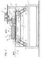
- the boxing apparatus 1 includes a conveyance apparatus 2 that conveys a group of items X ... X in a conveyance direction indicated by the arrow "a"; a loading apparatus 3, disposed on the upper-stream side of the conveyance apparatus 2, that carries in a loading direction indicated by the arrow "b" the items X ... X supplied, for example, from a packaging apparatus disposed further upstream, and loads them onto the conveyance apparatus 2 at the receiving position P1; a placing apparatus 4 disposed near the receiving position P1 that receives items X ...
- the unloading apparatus 6 packs discharged items X ... X into a cardboard box Y, and conveys the cardboard box Y further downstream, in the direction indicated by the arrow "d.”
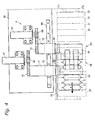
- the conveyance apparatus 2 includes a front/rear pair of shafts 13 and 14 rotatably axially supported within a main body frame 12 disposed on top of a base 11. At predetermined positions on the front shaft 13, four sprockets 15a through 15d are attached, and at predetermined positions on the rear shaft 14, four sprockets 16a through 16d are attached. Of these sprockets 15a through 15d, sprockets 15a and 15d are fixed to the shaft 13, while the sprockets 15b and 15c are rotatably supported by the shaft 13. Of the sprockets 16a through 16d, sprockets 16a and 16d are rotatably supported by the shaft 14, while the sprockets 16b and 16c are fixed to the shaft 14.
- Each of annular chains 17a through 17d is wound, respectively, between the opposing pairs of front sprockets 15a through 15d and rear sprockets 16a through 16d.
- receiving members 18 ... 18, which support these chains 17a through 17d (only one receiving member is shown in Figure 1).
- a timing belt 22 is wound between a pulley 20 attached to an output axis of a motor 19 disposed toward the front of the main body frame 12 and a pulley 21 attached near the left side end of the front shaft 13.
- a timing belt 26 is wound between a pulley 24 attached to an output axis of a motor 23 disposed toward the rear of the main body frame 12 and a pulley 25 attached near the left side end of the rear shaft 14.
- the conveyance apparatus 2 also includes a first items-group holding mechanism 27, coupled to and bridging the pair of chains 17a and 17d and appearing in the front in the example shown in the figures, that holds an items group X ... X, and a rear second items-group holding mechanism 28, coupled to and bridging the pair of chains 17b and 17c, which also holds an items group X ... X.
- the items-group holding mechanisms 27 and 28 can move independently of each other through the drive of the motors 19 and 23, respectively.
- the conveyance routes of the items group X ...X are the routes in which the first and second items-group holding mechanisms 27 and 28 move along the chains 17a-17d between the receiving position P1 and the discharging position P2.
- first and second items-group holding mechanisms 27 and 28 will be explained using the second items-group holding mechanism 28 as an example.
- a front-rear pair of first and second holding members 29 and 30, which are L-shaped when seen from the side, are provided bridging the pair of chains 17b and 17c, with a predetermined space therebetween.
- bottom plate members 31 ... 31, which are elongated in the conveyance width direction, are provided between the holding members 29 and 30; in the example in the figures, 12 such bottom plate members 31 are provided.
- the second holding member 30 and the bottom plate members 31 are provided on top of the chains 17b and 17c, with spacers 32 ... 32 respectively interposed therebetween.
- the first and second holding members 29 and 30 and the bottom plate members 31 ... 31 are detachably supported on the chains 17b and 17c.
- the ends extending upwards of the first and second holding members 29 and 30 are comb-shaped, with five cutaways 29a ... 29a and 30a ... 30a, formed respectively thereupon.
- a guide member 33 is provided along the conveyance direction indicated by the arrow "a,” extending from near the receiving position P1 to near the discharge position P2 (see Figures 1 and 2).
- a contact part 33a is provided at the receiving position P1 side of the guide member 33 with a large surface area, against which the sides of items X received from the loading apparatus 3 can come into contact.
- the loading apparatus 3 is an apparatus disposed on the upper-stream side of the conveyance apparatus 2, that is, at the receiving position P1, and is disposed perpendicular to the conveyance direction "a"; it loads items X ... X supplied in a sideways position from the upstream side onto the placing apparatus 4 or conveyance apparatus 2, putting such items into an upright position.
- This loading apparatus 3 includes a first belt 41 the running surface of which is vertical; a second belt 42 the running surface of which opposes the first belt 41 at the placing apparatus 4 side but is twisted so that its running surface becomes horizontal on the upper-stream side; a third belt 43 disposed beneath the first and second belts 41 and 42 that extends to near the conveyance apparatus 2 and has a horizontal running surface; and fourth and fifth belts 44 and 45, disposed on the lower-stream side of the first and second belts 41 and 42 and having vertical running surfaces that oppose each other.
- These belts 41 through 45 are driven by a drive source that is not shown in the figures.
- This loading apparatus 3 is constituted so that the space between the first and second belts 41 and 42 and the space between the fourth and fifth belts 44 and 45 are adjustable.
- this loading apparatus 3 includes a side frame 47a provided on top of, and, as seen in the figures, on the left side of, the frame 46 connected to the left side of the base 11, and a side frame 47b disposed on the right so as to oppose the side frame 47a.
- a screw shaft 49 is provided that screws into a threaded sleeve 48 that is fixed to the side frame 47b; attached to the end of the screw shaft 49 that protrudes from the side frame 47a is a handle 50 for operating this screw shaft 49.
- Guide rods 52, 52 which pass through sleeves 51, 51 (only the latter is shown in Figure 7), are provided between side frames 47a and 47b, to the front and rear (in terms of conveyance direction "b") of and below the screw shaft 49, with an appropriate space therebetween; the right ends of the sleeves 51, 51 are fixed on the side frame 47b, and the left ends are fixed on the side frame 47a.
- the first belt 41 is wound between a front/rear pair of rollers 54, 54 that are rotatably axially supported on the side frame 47a via a bracket 53 fixed to the side frame 47a and that make the running surface of the first belt 41 vertical;
- the second belt 42 is wound between a roller 55 that is rotatably axially supported on the upstream side of the side frame 47b and makes the running surface in this vicinity horizontal and a roller 57 that is rotatably axially supported on the side frame 47b via a bracket 56 fixed to the side frame 47b downstream side and that makes the running surface of the second belt 42 in this vicinity vertical.
- the third belt 43 is wound around a front/rear pair of rollers 58, 58 (only the latter is shown in Figure 7), which are rotatably axially supported between the side frames 47a and 47b.
- the fourth and fifth belts 44 and 45 are each wound around a front/rear pair of rollers axially supported on the side frames 47a, 47b via brackets 53 and 56.
- a photoelectric sensor 59 is provided at the downstream end of the loading apparatus 3, for the purpose of detecting items X ... X for loading from the loading apparatus 3 to the placing apparatus 4.
- the placing apparatus 4 is disposed on a table 62 supported by a frame 61 provided on the base 11 near the receiving position P1.
- This placing apparatus 4 includes first and second rear end holding members 63, 64, for securely placing items X ... X loaded from the loading apparatus 3 onto the first and second items-group holding mechanisms 27, 28 of the conveyance apparatus 2 and for holding the rearmost end of an items group X ... X held by these items-group holding mechanisms 27, 28; the placing apparatus 4 causes these rear end holding members 63, 64 each to execute the box motion, as seen from the side, indicated by the arrows "g.”
- the first rear end holding member 63 which has an L shape when seen from the side and the rear end of which extends downwards, is attached to the bottom end of a rod 65a of a cylinder 65 for causing the vertical motion of the first rear end holding member 63; the first rear end holding member 63 is supported so as to be able to move vertically, guided by two guide rods 66, 66.
- a pinion 68 is attached to an output axis of a motor 67 disposed on the table 62.
- a long arm member 71 is fixed to a linear bearing 70 in a direction orthogonal to the conveyance direction "a.”
- the linear bearing 70 slidably engages with a guide rail 69 disposed on the table 62.
- the guide rail 69 is elongated in the conveyance direction "a.”
- On one end of the arm member 71 is fixed a rack 72, which engages with the pinion 68; on the other end, the cylinder 65 is fixed.
- the first rear end holding member 63 can move horizontally along the conveyance direction "a.”
- the first rear end holding member 63 is able to execute the above-mentioned box motion.
- the second rear end holding member 64 which has an L shape when seen from the side and the front end of which extends downward, moves vertically and horizontally in the same manner as the first rear end holding member 63, and so an explanation of such movement will not be repeated.
- the respective ends of the first and second rear end holding members 63, 64 that extend downwards are comb-shaped so as to be able to pass through each other; the first and second rear end holding members 63, 64 are also formed so as to be able to pass through each other in the horizontal plane. Furthermore, the ends of the first and second rear end holding members 63, 64 are formed so as to be capable of passing through the upward ends of the first and second holding members 29, 30.
- the discharge apparatus 5 is disposed on a table 81 that is connected to the top surface of the main body frame 12 so as to be perpendicular to the conveyance direction "a.”
- the discharge apparatus 5 includes a sheet-shaped pusher 82 that pushes out at once a group of items X ... X held by the items-group holding mechanisms 27, 28 and a cylinder 83 with a rod 83a to the end of which the pusher 82 is attached; the cylinder 83 causes the pusher 82 to advance in the direction indicated by the arrow "c.”
- the cylinder 83 is but one example, and that a solenoid or a motor or the like can be used to drive the pusher 82.
- the unloading apparatus 6 has a table 91 connected to the upper surface of the main body frame 12 and extending along the front/rear direction. After packaging into a cardboard box Y loaded on the table 91 a group of items X ... X discharged from the discharge apparatus 5, the unloading apparatus 6 uses suitable means to convey the cardboard box Y further downstream, in the direction indicated by the arrow "d."
- FIG 8 shows the control system for the boxing apparatus 1.
- the control system includes a control unit 92 that comprehensively controls the boxing apparatus 1.
- the control unit 92 has a memory unit 92a that stores initialization settings and a variety of control parameters for each type of item X, with a control program that controls the devices 2-6 as discussed below.
- the control unit 92 can also include other conventional components such as an input interface circuit, an output interface circuit, and storage devices such as a ROM (Read Only Memory) device and a RAM (Random Access Memory) device.
- the control unit 92 is operatively coupled to the devices 2-6 in a conventional manner.
- the internal RAM of the control unit 92 stores various control data.
- the control unit 92 is capable of selectively controlling any of the devices 2-6 in accordance with the control program.
- control unit 92 can be any combination of hardware and software that will carry out the functions of the present invention.
- "means plus function” clauses as utilized in the specification and claims should include any structure or hardware and/or algorithm or software that can be utilized to carry out the function of the "means plus function” clause.
- the control unit 92 outputs control signals to the conveyance apparatus 2, the loading apparatus 3, the placing apparatus 4, the discharge apparatus 5 and the unloading apparatus 6; it controls the driving of these apparatuses and accepts input of detection signals from the photoelectric sensor 59.
- the memory 92a stores such control parameters for each item X as movement patterns of the first and second rear end holding members 63, 64, intermittent drive timing for the chains 17a through 17d, the number of items X ... X to be received in a group, the running speed and running time for chains 17a through 17d from the receiving position P1 to the discharge position P2, and the advancing and receding strokes of the pusher 82 of the discharge apparatus 5.
- the items X are supplied in a sideways position to the loading apparatus 3 by, for example, an upstream device such as a packaging apparatus, the items X are successively put into an upright position by the first and second belts 41 and 42, and then even more securely put into an upright position by the four and fifth belts 44 and 45; after this, the items X are loaded onto the placing apparatus 4.
- an upstream device such as a packaging apparatus
- the third belt 43 the running surface of which is horizontal, is disposed beneath the first and second belts 41 and 42, the bottoms of the items X are well supported, and thus such problems as an item assuming an unwanted position or falling over are kept in check. Therefore, the item-sandwiching force between the first and second belts 41 and 42 does not have to be made damagingly large, and as a result such problems as bags tearing or contents being damaged by excessive sandwiching force are avoided.
- the loading of items is carried out at higher speed compared to when items are moved from a sideways to upright position in a group.
- the spaces between the first and second belts 41 and 42 and the space between the fourth and fifth belts 44 and 45 are adjustable, the spaces can be fitted to match the thickness of the supplied items X ... X, and the conveyance of the items X ... X becomes even more stable.
- the control unit 92 controls the respective driving for the placing apparatus 4, that is, for the first and second rear end holding members 63, 64; for the conveyance apparatus 2, that is, the chains 17a to 17d; for the discharge apparatus 5, that is, the cylinder 83; and for the unloading apparatus 6.
- first and second rear end holding members 63, 64 in the placing apparatus 4 will be explained in detail.
- the rearmost end of six items X ... X that have already been received are held in an upright position by the first rear end holding member 63.
- the six items X ... X are held closely packed, in the front by the first holding member 29 and in the rear by the first rear end holding member 63.
- a new item X1 is about to be loaded from the loading apparatus 3.
- the second rear end holding member 64 pulls back from its position as shown in Figure 3, and moves downward and to the rear of the new item X1 that is about to be loaded. Then, when the new item X1 has been loaded in an upright position at the aforementioned position indicated by the broken line, that is, between the first rear end holding member 63 in the front and the second rear end holding member 64 in the rear, one side of the item X1 comes in contact with the contact part 33a of the guide member 33, and the item X1 securely assumes a position on the second items-group holding mechanism 28. During that interval, the first rear end holding member 63 holds the rearmost end of the six items X ... X.
- the first rear end holding member 63 pulls back from its position indicated in Figure 10 and moves downward and to the rear of the item X2 that is about to be loaded. Then, the new item X2 is loaded at the aforementioned position indicated by the broken line, that is, between the second rear end holding member 64 in the front and the first rear end holding member 63 in the rear.
- first and second rear end holding members 63, 64 are formed so as to be able to pass through each other, the above-described movement by the first rear end holding member 63 is possible. Therefore, because the first rear end holding member 63 stands by to receive the new item X2, the item X2 can be more securely received, and problems such as the items falling into disarray or falling over when they are received can be avoided. During this interval, the second rear end holding member 64 is holding the rearmost end of the seven items X ... X, including the new item X1.
- the placing apparatus 4 when an item X is received from the loading apparatus 3, the rearmost end of an items group X ... X is held by the first and second rear end holding members 63, 64; therefore, even items X ... X that have difficulty standing on their own are held in a stable manner upright in the second items-group holding mechanism 28. Moreover, because the two rear end holding members 63, 64 are driven so that they alternate in holding the rearmost end of the items group X ... X, the placing of the items X ... X can be carried out with a greater speed.
- first and second rear end holding members 63, 64 are formed so that they pass through, and are passed through by, the first and second holding members 29 and 30. Therefore, when, for example, the initial item X is received by the second items-group holding mechanism 28, or when the final item X is received, because the first or second rear end holding member 63 or 64 are driven so that the first or second rear end holding member 63 or 64 and the first or second holding member 29 or 30 pass through each other, placing can be carried out at higher speed.
- the second items-group holding mechanism 28 has no partitioning members between the first and second holding members 29, 30, it can adapt to changes in the thickness of items X ... X or in the number of items in a group. Furthermore, because the first and second holding members 29, 30 of the second items-group holding mechanism 28 and the bottom plates 31 ... 31 can be detached and reattached from and to the chains 17b, 17c, there is even greater flexibility in adapting to changes in items. There is the additional merit that there is no need to make the items fit more tightly in the box during packaging, as is necessary in conventional conveyance apparatuses that use partitioning members.
- the second items-group holding mechanism 28 moves them as a group to the discharge position P2.
- the chains 17a, 17d run, causing the first items-group holding mechanism 27, onto which prior to this 14 other items X ... X had been loaded, to move to the discharge position 2, where it stops, as shown in Figures 1 and 2.
- the pusher 82 of the discharge apparatus 5 advances onto the conveyance route, the items X ... X contained on the first items-group holding mechanism 27 are pushed out all at once, into the cardboard box Y placed on the table 91 opposite the discharge device 5, with the conveyance apparatus 5 interposed therebetween, so that the items X ... X are compactly contained in an upright position, as shown by the broken lines in the Figure 2.
- the cardboard box Y, containing the items X ... X is conveyed further downstream by suitable means.
- the group of items X ... X is held in a stable manner by the front/rear first and second holding members 29, 30, there is no need for additional members during discharge by the pusher 82, such as a member for preventing the items X ... X from becoming disarrayed or a member for packing the items more tightly.
- the second items-group holding mechanism 28, containing 14 items X ... X arrives at the discharge position P2, which the first items-group holding mechanism 27 has just left, and the items X ... X are discharged in the same manner as described for the first items-group holding mechanism 27.
- the first items-group holding mechanism 27 receives the items X ... X at the receiving position P1 in the same manner as described for the second items-group holding mechanism 28.
- chains 17a, 17d and chains 17b, 17c are each driven independently and the items X ... X are being discharged at the discharge position P2 from the first items-group holding mechanism 27 or the second items-group holding mechanism 28, the second items-group holding mechanism 28 or the first items-group holding mechanism 27 is receiving another group of items X ... X from the loading apparatus 3 via the placing apparatus 4 at the receiving position P1. Therefore, these operations are performed without breaks, and the items X ... X are processed at high speed.
- a conveyance apparatus 101 conveys a group of items X ... X ( Figure 13 shows only one), while holding them in an upright position, in the direction indicated by the arrow "a.”
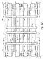
- This conveyance apparatus 101 includes six shafts 102 to 107 that are rotatably axially supported on the front and rear of a frame not shown in the figures.
- a roller 108 is attached to the front left shaft 102
- a roller 109 is attached to the front center shaft 103
- rollers 110 and 111 are attached to the front right shaft 104.
- Rollers 112 and 113 are attached to the rear left shaft 105
- a roller 114 is attached to the rear center shaft 106
- a roller 115 is attached to the rear right roller 107.
- rollers 108, 110, 113 and 115 are fixed, respectively, to the corresponding shafts 102, 104, 105, and 107, while the rollers 109, 111, 112 and 114 are rotatably supported, respectively, on the corresponding shafts 103 to 106.
- One of annular conveyance belts 116 to 119 is wound around each pair of opposing front/rear rollers 108 to 115.
- Each of timing belts 132 to 135 is wound, respectively, around one of pulleys 124 to 127 connected to the output axes of motors 120 to 123 disposed front and rear on the right and left below the annular conveyance belts 116 to 119 and the pulley from among pulleys 128 to 131 corresponding to the respective pulley 124 to 127 and connected to one end of one of the front and rear left and right shafts 102, 104, 105 and 107.
- motor 120 independently drives conveyance belt 116
- motor 121 independently drives conveyance belt 118
- motor 122 independently drives conveyance belt 117
- motor 123 independently drives conveyance belt 119.
- First holding members 136 and 137 and second holding members 138 and 139 which have an L shape when seen from the side and are formed in a comb shape because of five cutouts 136a ... 136a provided on the respective ends thereof that rise upwards, are attached onto the upper surfaces of the conveyance belts 116 to 119 in an alternating manner, in the conveyance direction "a," and in a detachable manner, via detaching/attaching mechanisms 140 ... 140.
- the front first items-group holding member 136 and second items-group holding member 138 constitute a first items-group holding mechanism 141
- the rear first items-group holding member 137 and second items-group holding member 139 constitute a second items-group holding mechanism 142.
- the first and second holding members 136 to 139 are able to pass through, and be passed through by, for example, the comb-shaped ends that extend downwards of the first and second rear end holding members 63, 64 described above in the first embodiment.
- the detaching/attaching mechanism 140 is provided between the first holding member 136 and the conveyance belt 116.
- the detaching/attaching mechanism 140 includes a hook member 143, which is a plate spring fixed to the bottom surface of the first holding member 136, and a receiving member 144 fixed to the upper surface of the conveyance belt 116.
- the hook member 143 engages with the receiving member 144 using left and right side portions that are formed with bent shapes that differ from each other, and two concavities provided on the left and right side, respectively, of the receiving member 144 and having differing shapes that correspond to the respective side portions of the hook member 143.
- the first holding member 136 is pushed down from above, causing the right side portion and the right concavity, which engage to a relatively shallow depth, to engage; thus the first holding member 136 is securely attached to the conveyance belt 116.
- the attaching and detaching of the holding members 136 to 139 onto the conveyance belts 116 to 119 can be performed easily. Therefore, the holding members 136 to 139 can be easily replaced depending on such factors as the dimensions of the item X to be conveyed, providing for even more stable conveyance of the items X ... X.
- support members 145 ... 145 are disposed that extend in the conveyance direction "a" and support the bottom surfaces of the holding members 136 to 139 and the bottom ends of the items X ... X. With such a constitution, the items X ... X held by the first and second holding mechanisms 141, 142 are conveyed in an even more stable manner.
- the space y1 between the front first holding member 136 linked to the conveyance belt 116 and the rear second holding member 138 linked to the conveyance belt 117 can be adjusted appropriately by causing either of the conveyance belts 116 or 117 to run. If, after adjustment, the running speeds of the conveyance belts 116 and 117 are controlled so as to be equal, the two holding members 136 and 138 will move in a state in which the space y1 is maintained.
- the space y2 between the rear first holding member 137 and the second holding member 139 namely, the item holding space in the second items-group holding mechanism 142, can be adjusted to appropriately.
- the spaces y1 and y2 are usually set to be the same, but they may be set to be different.
- the conveyance apparatus 101 can be used for various application and can more easily be adjusted to the conveyance of items having differing thickness and grouped in different numbers. Needless to say, by providing this conveyance apparatus 101 in place of the conveyance apparatus 2 in the first embodiment, a boxing apparatus with even greater applicability can be provided.
- the spaces between the first and second belts 41, 42 and between the fourth and fifth belts 44, 45 of the loading apparatus 3 were adjusted through the operation of the handle 50; this may be replaced with a motor or other drive source.
- operational parameters for each type of item can be stored in the memory 92a, so that the setting of such spaces is performed automatically.
- the first and second rear end holding members 63, 64 move vertically and horizontally (in this case, in the conveyance direction), executing a box motion when seen from the side; however, they may be constituted to perform a box motion when seen in a plan view, that is, a box motion within a horizontal plane.
- the rear end holding members move in the conveyance direction "a" and in the conveyance width direction, the rear end holding members can be disposed without any restrictions due to the vertical dimensions of the items X ... X to be received, resulting in a conveyance apparatus with even more widespread applicability.
- first and second rear end holding members 63, 64 were used; however, in cases where items that are particularly capable of standing on their own are received, or cases where high-speed processing at or above a certain level is not required, it would be fine to use only one of the rear end holding members.
- a guide member for guiding the items X ... X discharged by the discharge apparatus 5 may be provided between the conveyance apparatus 2 and the unloading apparatus 6 in the first embodiment.
- a rod-shaped support member extending in the conveyance direction "a" may be provided between the conveyance apparatus 2 and the unloading apparatus 6 in the first embodiment.
- This support member provides greater support from the right side for the items X ... X contained in the items-group holding mechanisms 27, 28 while they are moved or are stopped, and pulls away upward during discharge, and thus is constituted so as not to interfere with the pusher 82.
Landscapes
- Engineering & Computer Science (AREA)
- Mechanical Engineering (AREA)
- Container Filling Or Packaging Operations (AREA)
- Attitude Control For Articles On Conveyors (AREA)
- Special Conveying (AREA)
- Specific Conveyance Elements (AREA)
Applications Claiming Priority (2)
| Application Number | Priority Date | Filing Date | Title |
|---|---|---|---|
| JP2002012545 | 2002-01-22 | ||
| JP2002012545A JP3974409B2 (ja) | 2002-01-22 | 2002-01-22 | 搬送装置及びそれを備えた箱詰め装置 |
Publications (2)
| Publication Number | Publication Date |
|---|---|
| EP1329384A1 EP1329384A1 (en) | 2003-07-23 |
| EP1329384B1 true EP1329384B1 (en) | 2006-08-09 |
Family
ID=19191748
Family Applications (1)
| Application Number | Title | Priority Date | Filing Date |
|---|---|---|---|
| EP03250400A Expired - Lifetime EP1329384B1 (en) | 2002-01-22 | 2003-01-22 | Conveyance and boxing apparatus for a group of items |
Country Status (8)
| Country | Link |
|---|---|
| US (3) | US6907980B2 (https=) |
| EP (1) | EP1329384B1 (https=) |
| JP (1) | JP3974409B2 (https=) |
| KR (1) | KR100954535B1 (https=) |
| CN (1) | CN1298590C (https=) |
| AT (1) | ATE335661T1 (https=) |
| AU (1) | AU2003200187B2 (https=) |
| DE (1) | DE60307332T2 (https=) |
Cited By (1)
| Publication number | Priority date | Publication date | Assignee | Title |
|---|---|---|---|---|
| KR100954535B1 (ko) * | 2002-01-22 | 2010-04-23 | 가부시끼가이샤 이시다 | 반송 장치 및 그것을 구비한 봉지 포장 장치 |
Families Citing this family (79)
| Publication number | Priority date | Publication date | Assignee | Title |
|---|---|---|---|---|
| AUPS307202A0 (en) * | 2002-06-21 | 2002-07-11 | Manufacturing Solutions Pty Ltd | Device for guiding flexible packages into a case |
| US6877294B2 (en) | 2002-11-04 | 2005-04-12 | Kimberly-Clark Worldwide, Inc. | Automatic repacking and accumulation system |
| AU2003290553A1 (en) * | 2002-11-04 | 2004-06-07 | Kimberly-Clark Worldwide, Inc. | Method and device for stacking and packaging of articles |
| US7108155B2 (en) | 2002-11-04 | 2006-09-19 | Kimberly-Clark Worldwide, Inc. | Metering drum for an automatic accumulation system |
| US6918485B2 (en) | 2002-11-04 | 2005-07-19 | Kimberly-Clark Worldwide, Inc. | Orientation detection and control system |
| US6884016B2 (en) | 2002-11-04 | 2005-04-26 | Kimberly-Clark Worldwide, Inc. | Positioning system for an automatic accumulation system |
| US6823981B2 (en) | 2002-11-04 | 2004-11-30 | Kimberly-Clark Worldwide, Inc. | Conveyor system for an automatic accumulation system |
| US7159375B2 (en) | 2003-10-08 | 2007-01-09 | Kimberly-Clark Worldwide, Inc. | Multi-product accumulating and packing system |
| ITBO20040085A1 (it) * | 2004-02-19 | 2004-05-19 | Azionaria Costruzioni Acma Spa | Unita' per l'alimentazione di una successione ordinata di prodotti |
| ITBO20040346A1 (it) * | 2004-05-31 | 2004-08-31 | Marchesini Group Spa | Unita' per il trasferimento di articoli da una macchina confezionatrice ad una linea di alimentazione di una macchina astucciatrice |
| DE102004042474A1 (de) * | 2004-09-02 | 2006-03-23 | Krones Ag | Vorrichtung zum Gruppieren von Stückgut |
| JP2006137456A (ja) * | 2004-11-12 | 2006-06-01 | Ishida Co Ltd | 搬送装置及びそれを備えた箱詰め装置 |
| US20060252591A1 (en) * | 2005-05-03 | 2006-11-09 | Johnson Food Equipment, Inc. | Belt conveyor with external drive |
| JP4745730B2 (ja) * | 2005-06-22 | 2011-08-10 | 株式会社イシダ | 搬送装置 |
| US7494002B2 (en) | 2005-11-17 | 2009-02-24 | Ishida Co., Ltd. | Conveyance apparatus, and weighing and packaging system provided therewith |
| US7900766B2 (en) * | 2006-07-14 | 2011-03-08 | Ishida Co., Ltd. | Conveyance device and packing device provided therewith |
| SE0602330L (sv) * | 2006-11-03 | 2008-05-04 | Tetra Laval Holdings & Finance | Anordning för gruppering av föremål på en driven transportbana |
| DE102007049424A1 (de) * | 2007-10-12 | 2009-04-23 | Bhs Corrugated Maschinen- Und Anlagenbau Gmbh | Wellpappe-Streifen-Transport-Einrichtung |
| JP4474618B2 (ja) * | 2008-03-18 | 2010-06-09 | オリオン機械工業株式会社 | 製品集積装置 |
| ITRA20080014A1 (it) * | 2008-04-17 | 2009-10-18 | Nicola Antonacci | Macchina e metodo per il riempimento di cassette con cestini di prodotti ortofrutticoli preconfezionati. |
| DE202008011454U1 (de) * | 2008-08-28 | 2008-10-30 | Khs Ag | Vorrichtung zur Abteilung von Produktgruppen |
| JP5302039B2 (ja) * | 2009-02-16 | 2013-10-02 | 株式会社イシダ | 箱詰め装置 |
| EP2316737A1 (en) * | 2009-10-27 | 2011-05-04 | Tetra Laval Holdings & Finance S.A. | Separating unit for separating a batch of packages of a product which is pourable within a tube of packaging material from a row of packages, and related method |
| WO2012011360A1 (ja) * | 2010-07-23 | 2012-01-26 | 株式会社瑞光 | 物品の整列搬送装置 |
| CN102114960A (zh) * | 2010-12-29 | 2011-07-06 | 上海烟草集团有限责任公司 | 成品件烟多工位机器人码垛工艺 |
| US8448776B2 (en) * | 2011-03-14 | 2013-05-28 | The Procter & Gamble Company | Apparatus for diverting products and methods of handling products |
| DE102011084469A1 (de) | 2011-10-13 | 2013-04-18 | Robert Bosch Gmbh | Separiervorrichtung |
| WO2013109900A2 (en) * | 2012-01-18 | 2013-07-25 | Douglas Machine Inc. | Article metering apparatus, system & methods |
| DE102012204013B4 (de) | 2012-03-14 | 2025-10-02 | Krones Aktiengesellschaft | Verfahren und Vorrichtung zur Übergabe von Artikellagen zwischen benachbarten Modulen |
| DE102012204027B4 (de) | 2012-03-14 | 2024-10-24 | Krones Ag | Transfereinheit zur horizontalen Verschiebung von Artikellagen zwischen benachbarten Modulen |
| CN104220349B (zh) * | 2012-04-12 | 2017-07-14 | 勒舍包装技术有限公司 | 用于传送块状产品的设备和方法 |
| DE102012219886A1 (de) * | 2012-10-31 | 2014-05-15 | Krones Aktiengesellschaft | Handhabungseinrichtung eines Förderabschnittes zur Artikelförderung und Verfahren zur Steuerung einer derartigen Handhabungseinrichtung |
| KR101976097B1 (ko) | 2012-11-12 | 2019-05-09 | 쇼오트 아게 | 의료, 의약 또는 화장품 용도의 물질용 용기를 조작 또는 처리하는 프로세스 및 장치 |
| JP6156629B2 (ja) * | 2013-05-08 | 2017-07-05 | 東洋製罐株式会社 | 矩形形状品の箱詰め装置 |
| EP2810882A1 (de) * | 2013-06-05 | 2014-12-10 | Multivac Sepp Haggenmüller GmbH & Co. KG | Mehrzugbandeinrichtung und Verpackungsanlage |
| EP2818421A1 (de) * | 2013-06-25 | 2014-12-31 | Multivac Sepp Haggenmüller GmbH & Co. KG | Schalenverschließmaschine mit Trayzuführung und Verfahren für eine Verpackungsanlage |
| ITMI20131999A1 (it) * | 2013-11-29 | 2015-05-30 | Altopack Spa | Macchinario per l'inscatolamento di confezioni di prodotti alimentari a sacchetto con fondo piano o a cuscino. |
| PL2894102T3 (pl) * | 2014-01-10 | 2017-03-31 | Tiber Pack, S.R.L. | Maszyna i sposób pakowania w kartony, szczególnie do produktów poukładanych w równoległe i przestawione względem siebie rzędy |
| DE102014206988B4 (de) | 2014-04-11 | 2025-04-30 | Krones Aktiengesellschaft | Verfahren und Vorrichtung zur horizontalen Verschiebung von Artikelgruppen |
| DE102014215106A1 (de) * | 2014-07-31 | 2016-02-04 | Loesch Verpackungstechnik Gmbh | Verfahren und Vorrichtung zum Fördern von stückigen Produkten |
| CN104326229B (zh) * | 2014-09-03 | 2016-09-14 | 奇瑞汽车股份有限公司 | 一种工件传送设备 |
| US11059185B2 (en) * | 2014-10-03 | 2021-07-13 | Frito-Lay North America, Inc. | Apparatus and method for transferring a pattern from a universal surface to an ultimate package |
| JP6534820B2 (ja) * | 2015-01-23 | 2019-06-26 | 株式会社イシダ | 押し込み機構、および、これを備える箱詰め装置 |
| GB2534588A (en) * | 2015-01-28 | 2016-08-03 | Vancebuild Ltd | Apparatus and method relating to flow wrapping |
| US9586769B2 (en) * | 2015-05-26 | 2017-03-07 | Dyco, Inc. | System and method for forming and moving an article array |
| US10144596B2 (en) * | 2015-05-26 | 2018-12-04 | Dyco, Inc. | System and method for forming and moving an article array |
| US9540183B2 (en) * | 2015-06-09 | 2017-01-10 | The Procter & Gamble Company | Nestable transport members and a corresponding track |
| CN105059601B (zh) * | 2015-07-28 | 2017-10-27 | 江苏仅一包装技术有限公司 | 一种包装机械跟随喂料机构 |
| US10759550B2 (en) | 2015-09-25 | 2020-09-01 | Douglas Machine Inc. | Intermittent case packer assembly and methods |
| CN105438780B (zh) * | 2015-12-16 | 2018-10-30 | 嵊州市银海机械有限公司 | 一种应用于金属件的下料检测设备 |
| DE202016101207U1 (de) | 2016-03-07 | 2017-06-13 | Autefa Solutions Germany Gmbh | Transportvorrichtung zum Reihen-weisen Umsetzen von umfallgefährdeten Stückgütern und zur Lagenbildung |
| CH712327A1 (de) | 2016-04-07 | 2017-10-13 | Alpla Werke Alwin Lehner Gmbh & Co Kg | Beladungsvorrichtung und Verfahren zur Beladung von Lager- und Transportbehältern für Kunststoffbehältnisse. |
| JP6729217B2 (ja) * | 2016-09-07 | 2020-07-22 | 株式会社ダイフク | 物品積載設備 |
| JP6930838B2 (ja) * | 2017-02-06 | 2021-09-01 | 株式会社オーエム機械 | 収容数可変移送システム |
| IT201700060052A1 (it) * | 2017-06-01 | 2018-12-01 | Gd Spa | Sistema di trasferimento di un gruppo di componenti di sigarette elettroniche da una prima stazione operativa ad una seconda stazione operativa |
| CN107226237B (zh) * | 2017-06-08 | 2023-07-28 | 湖南金能自动化设备有限公司 | 全自动高速理料机及其理料方法 |
| CN107601021A (zh) * | 2017-10-26 | 2018-01-19 | 高达食品设备有限公司 | 一种传送装载装置及其装载方法 |
| CN108147079B (zh) * | 2017-12-15 | 2020-01-14 | 佛山市万良商贸有限公司 | 一种双磁力定向元器件排料装置 |
| US10836523B2 (en) * | 2018-02-27 | 2020-11-17 | The Challenge Printing Co. | Tray filling apparatus for leaflets |
| MX2020012425A (es) | 2018-05-23 | 2021-02-09 | Metalquimia Sau | Sistema y metodo de carga de articulos alimentarios. |
| CN108820316B (zh) * | 2018-07-02 | 2021-02-26 | 芜湖懒人智能科技有限公司 | 一种间歇式自夹取上料移动装置 |
| CN108792579B (zh) * | 2018-07-03 | 2024-03-29 | 苏州邦勒尔自动化科技有限公司 | 铁芯输送装置 |
| DE102018211859A1 (de) * | 2018-07-17 | 2020-01-23 | Krones Ag | Vorrichtung und Verfahren zum Puffern von Stückgütern |
| CN109229537A (zh) * | 2018-08-08 | 2019-01-18 | 安徽晨讯智能科技有限公司 | 一种纸管自动打包装载装置 |
| CN109178484B (zh) * | 2018-10-12 | 2023-10-31 | 安徽海思达机器人有限公司 | 一种四盒或六盒装箱装置 |
| US10889452B1 (en) * | 2018-10-30 | 2021-01-12 | Douglas Machine Inc. | Article accumulation and article group formation |
| CN110329607B (zh) * | 2019-04-26 | 2021-06-22 | 江苏仅一联合智造有限公司 | 一种补袋机构流程 |
| CN110239774B (zh) * | 2019-04-26 | 2024-05-14 | 江苏仅一联合智造有限公司 | 一种高效补袋机 |
| US11807462B2 (en) * | 2019-05-21 | 2023-11-07 | Westrock Packaging Systems, Llc | Flexible pitch product metering system |
| CN112027525B (zh) * | 2019-12-25 | 2024-12-10 | 青岛海科佳智能科技股份有限公司 | 星形双侧推料装置 |
| CN111301743B (zh) * | 2020-03-30 | 2025-02-18 | 浙江希望机械有限公司 | 一种高速薄膜捆扎机 |
| CN111942654B (zh) * | 2020-06-10 | 2021-09-07 | 安徽正熹标王新能源有限公司 | 一种电池包装装置 |
| CN112093464B (zh) * | 2020-08-26 | 2022-04-22 | 绩溪县徽洋车桥有限责任公司 | 一种排气歧管加工后的装架装置 |
| CN111924488B (zh) * | 2020-09-05 | 2022-06-21 | 张家港市盛港绿色防火建材有限公司 | 一种自动化控制翻转装置及翻转方法 |
| CN113526088B (zh) * | 2021-01-27 | 2022-06-24 | 哈尔滨商业大学 | 一种含下压气缸的带有检测功能的物流包裹输送装置 |
| CN112978332B (zh) * | 2021-02-05 | 2022-06-24 | 浙江理工大学 | 一种扦插柳枝自动喂入装置及其喂入方法 |
| CN113385915B (zh) * | 2021-07-05 | 2022-04-08 | 全椒赛德利机械有限公司 | 基于管片式散热器加工用散热片叠合排列装置 |
| JP7843161B2 (ja) * | 2022-03-10 | 2026-04-09 | 株式会社京都製作所 | 包装体集積装置、及び包装体集積方法 |
| JP7809352B2 (ja) * | 2023-08-25 | 2026-02-02 | 株式会社フジキカイ | 物品供給装置 |
Family Cites Families (23)
| Publication number | Priority date | Publication date | Assignee | Title |
|---|---|---|---|---|
| US3333674A (en) | 1965-09-29 | 1967-08-01 | Textile Machine Works | Case loader |
| US4098392A (en) * | 1976-10-26 | 1978-07-04 | Greene William F | Potato chips processing machine |
| CH664127A5 (de) * | 1984-07-31 | 1988-02-15 | Sig Schweiz Industrieges | Vorrichtung zum abtrennen von gruppen bestimmter laenge von einem stapel kontinuierlich zugefuehrter gegenstaende. |
| US4768642A (en) * | 1987-06-16 | 1988-09-06 | Kimberly-Clark Corporation | Multiple conveyors with overlapping material handling device paths |
| JPH0767939B2 (ja) * | 1990-07-31 | 1995-07-26 | 東亜機工株式会社 | サニタリー製品積込み計数装置 |
| US5095684A (en) * | 1990-10-31 | 1992-03-17 | Food Machinery Sales, Inc. | On edge cookie loader |
| JP2553999B2 (ja) | 1992-01-20 | 1996-11-13 | 株式会社フジキカイ | 物品の幅寄せ搬送方法および装置 |
| JP2651555B2 (ja) | 1992-02-05 | 1997-09-10 | 株式会社フジキカイ | 物品の集合搬送装置 |
| JP4318322B2 (ja) * | 1993-05-07 | 2009-08-19 | グラプハ−ホルディング・アクチエンゲゼルシヤフト | 並列して起立している刷紙に対して垂直方向で指向して堆積体を形成するための装置 |
| US5457935A (en) | 1994-07-12 | 1995-10-17 | Kope; David P. | Parallel linkage loading RAM |
| DE4435981C2 (de) | 1994-10-08 | 2000-05-31 | Buehler Optima Maschf | Einrichtung zum Zuführen von zu verpackenden Produkten zu einer Verpackungsmaschine |
| JPH08183505A (ja) | 1994-12-29 | 1996-07-16 | Matsushima Denki Seisakusho:Kk | 立詰装置 |
| JP3628086B2 (ja) | 1995-10-09 | 2005-03-09 | 株式会社川島製作所 | スナック菓子包装袋の搬送方法、及びスナック菓子包装袋の搬送・箱詰め方法 |
| JP4039501B2 (ja) * | 1998-02-09 | 2008-01-30 | 株式会社インターパック | 物品の自動集合装置 |
| US6419442B1 (en) * | 1998-08-25 | 2002-07-16 | Dorner Mfg. Corp. | Mechanism and method for forming a stack of articles |
| US6339248B1 (en) * | 1999-11-15 | 2002-01-15 | Omnivision Technologies, Inc. | Optimized floating P+ region photodiode for a CMOS image sensor |
| US6182814B1 (en) * | 2000-03-03 | 2001-02-06 | Sig Pack, Inc., Doboy Division | Inline vacuum slug feeder |
| US6909162B2 (en) * | 2001-11-02 | 2005-06-21 | Omnivision Technologies, Inc. | Surface passivation to reduce dark current in a CMOS image sensor |
| KR100494030B1 (ko) * | 2002-01-10 | 2005-06-10 | 매그나칩 반도체 유한회사 | 이미지센서 및 그 제조 방법 |
| JP3974409B2 (ja) * | 2002-01-22 | 2007-09-12 | 株式会社イシダ | 搬送装置及びそれを備えた箱詰め装置 |
| US6969631B2 (en) * | 2003-06-16 | 2005-11-29 | Micron Technology, Inc. | Method of forming photodiode with self-aligned implants for high quantum efficiency |
| US6900484B2 (en) * | 2003-07-30 | 2005-05-31 | Micron Technology, Inc. | Angled pinned photodiode for high quantum efficiency |
| KR100544957B1 (ko) * | 2003-09-23 | 2006-01-24 | 동부아남반도체 주식회사 | 시모스 이미지 센서의 제조방법 |
-
2002
- 2002-01-22 JP JP2002012545A patent/JP3974409B2/ja not_active Expired - Fee Related
-
2003
- 2003-01-21 US US10/347,302 patent/US6907980B2/en not_active Expired - Fee Related
- 2003-01-22 AU AU2003200187A patent/AU2003200187B2/en not_active Ceased
- 2003-01-22 KR KR1020030004410A patent/KR100954535B1/ko not_active Expired - Fee Related
- 2003-01-22 EP EP03250400A patent/EP1329384B1/en not_active Expired - Lifetime
- 2003-01-22 CN CNB031017746A patent/CN1298590C/zh not_active Expired - Fee Related
- 2003-01-22 AT AT03250400T patent/ATE335661T1/de not_active IP Right Cessation
- 2003-01-22 DE DE60307332T patent/DE60307332T2/de not_active Expired - Lifetime
-
2004
- 2004-04-27 US US10/832,287 patent/US6953113B2/en not_active Expired - Fee Related
-
2005
- 2005-04-28 US US11/116,193 patent/US7066317B2/en not_active Expired - Fee Related
Cited By (1)
| Publication number | Priority date | Publication date | Assignee | Title |
|---|---|---|---|---|
| KR100954535B1 (ko) * | 2002-01-22 | 2010-04-23 | 가부시끼가이샤 이시다 | 반송 장치 및 그것을 구비한 봉지 포장 장치 |
Also Published As
| Publication number | Publication date |
|---|---|
| CN1433939A (zh) | 2003-08-06 |
| US20040195074A1 (en) | 2004-10-07 |
| JP3974409B2 (ja) | 2007-09-12 |
| KR100954535B1 (ko) | 2010-04-23 |
| CN1298590C (zh) | 2007-02-07 |
| KR20030063244A (ko) | 2003-07-28 |
| AU2003200187A1 (en) | 2003-08-07 |
| AU2003200187B2 (en) | 2009-02-26 |
| US20030136641A1 (en) | 2003-07-24 |
| US20050189197A1 (en) | 2005-09-01 |
| DE60307332T2 (de) | 2007-04-12 |
| US6907980B2 (en) | 2005-06-21 |
| DE60307332D1 (de) | 2006-09-21 |
| JP2003212338A (ja) | 2003-07-30 |
| US6953113B2 (en) | 2005-10-11 |
| US7066317B2 (en) | 2006-06-27 |
| ATE335661T1 (de) | 2006-09-15 |
| EP1329384A1 (en) | 2003-07-23 |
Similar Documents
| Publication | Publication Date | Title |
|---|---|---|
| EP1329384B1 (en) | Conveyance and boxing apparatus for a group of items | |
| EP1298079B1 (en) | Conveyance apparatus and boxing system | |
| US6634487B2 (en) | Conveying apparatus for forming and loading groups of containers | |
| JP4885137B2 (ja) | 個体商品をグループ化するための装置 | |
| JP5704705B2 (ja) | 商品供給・集積装置および商品供給・集積方法 | |
| US4443995A (en) | Metering device and method | |
| JP2003212338A5 (https=) | ||
| GB1559796A (en) | Apparatus for handling packets | |
| KR102147805B1 (ko) | 고속으로 상품을 포장할 수 있는 낱개상품 정렬장치 | |
| JPH0639703U (ja) | 包装機械 | |
| JP6109509B2 (ja) | 物品整列供給装置 | |
| US4235329A (en) | Article grouping and tiering apparatus | |
| RU99115467A (ru) | Способ и устройство для подачи заготовок оберточного материала в упаковочную машину | |
| JP2003212339A (ja) | 搬送装置及びそれを備えた箱詰め装置 | |
| JPH07285654A (ja) | 物品の集合搬送装置 | |
| JP2005239226A (ja) | 製品搬送装置および段ボールケーサ | |
| JP2009057088A (ja) | 餃子のトレー詰めのための起立姿勢保持装置 | |
| JP3974484B2 (ja) | 物品搬送装置及びそれを備えた物品梱包装置 | |
| JP4180704B2 (ja) | 箱詰め装置 | |
| IT8922698A1 (it) | Dispositivo orientatore e caricatore di fiale in genere, e di fiale-siringa in particolare | |
| JP3974410B2 (ja) | 搬送装置及びそれを備えた箱詰め装置 | |
| JP4050108B2 (ja) | 物品搬送装置及びそれを備えた物品梱包装置 | |
| JPH06321318A (ja) | 物品集積供給方法および装置 | |
| JP2004168491A (ja) | 物品搬送装置及びそれを備えた箱詰め装置 | |
| JP2000211733A (ja) | 製品の搬送姿勢変更装置 |
Legal Events
| Date | Code | Title | Description |
|---|---|---|---|
| PUAI | Public reference made under article 153(3) epc to a published international application that has entered the european phase |
Free format text: ORIGINAL CODE: 0009012 |
|
| AK | Designated contracting states |
Designated state(s): AT BE BG CH CY CZ DE DK EE ES FI FR GB GR HU IE IT LI LU MC NL PT SE SI SK TR |
|
| AX | Request for extension of the european patent |
Extension state: AL LT LV MK RO |
|
| 17P | Request for examination filed |
Effective date: 20040113 |
|
| AKX | Designation fees paid |
Designated state(s): AT BE BG CH CY CZ DE DK EE ES FI FR GB GR HU IE IT LI LU MC NL PT SE SI SK TR |
|
| GRAP | Despatch of communication of intention to grant a patent |
Free format text: ORIGINAL CODE: EPIDOSNIGR1 |
|
| RIN1 | Information on inventor provided before grant (corrected) |
Inventor name: IWASA, SEISAKU,ISHIDA CO., LTD Inventor name: OISHI, YOSHINORI,ISHIDA SANGYO CO., LTD. |
|
| GRAS | Grant fee paid |
Free format text: ORIGINAL CODE: EPIDOSNIGR3 |
|
| RIN1 | Information on inventor provided before grant (corrected) |
Inventor name: OISHI, YOSHINORI, C/O OISHI SANGYO CO., LTD Inventor name: IWASA, SEISAKU, C/O ISHIDA CO., LTD |
|
| GRAA | (expected) grant |
Free format text: ORIGINAL CODE: 0009210 |
|
| AK | Designated contracting states |
Kind code of ref document: B1 Designated state(s): AT BE BG CH CY CZ DE DK EE ES FI FR GB GR HU IE IT LI LU MC NL PT SE SI SK TR |
|
| PG25 | Lapsed in a contracting state [announced via postgrant information from national office to epo] |
Ref country code: IT Free format text: LAPSE BECAUSE OF FAILURE TO SUBMIT A TRANSLATION OF THE DESCRIPTION OR TO PAY THE FEE WITHIN THE PRESCRIBED TIME-LIMIT;WARNING: LAPSES OF ITALIAN PATENTS WITH EFFECTIVE DATE BEFORE 2007 MAY HAVE OCCURRED AT ANY TIME BEFORE 2007. THE CORRECT EFFECTIVE DATE MAY BE DIFFERENT FROM THE ONE RECORDED. Effective date: 20060809 Ref country code: CZ Free format text: LAPSE BECAUSE OF FAILURE TO SUBMIT A TRANSLATION OF THE DESCRIPTION OR TO PAY THE FEE WITHIN THE PRESCRIBED TIME-LIMIT Effective date: 20060809 Ref country code: FI Free format text: LAPSE BECAUSE OF FAILURE TO SUBMIT A TRANSLATION OF THE DESCRIPTION OR TO PAY THE FEE WITHIN THE PRESCRIBED TIME-LIMIT Effective date: 20060809 Ref country code: BE Free format text: LAPSE BECAUSE OF FAILURE TO SUBMIT A TRANSLATION OF THE DESCRIPTION OR TO PAY THE FEE WITHIN THE PRESCRIBED TIME-LIMIT Effective date: 20060809 Ref country code: SI Free format text: LAPSE BECAUSE OF FAILURE TO SUBMIT A TRANSLATION OF THE DESCRIPTION OR TO PAY THE FEE WITHIN THE PRESCRIBED TIME-LIMIT Effective date: 20060809 Ref country code: NL Free format text: LAPSE BECAUSE OF FAILURE TO SUBMIT A TRANSLATION OF THE DESCRIPTION OR TO PAY THE FEE WITHIN THE PRESCRIBED TIME-LIMIT Effective date: 20060809 Ref country code: SK Free format text: LAPSE BECAUSE OF FAILURE TO SUBMIT A TRANSLATION OF THE DESCRIPTION OR TO PAY THE FEE WITHIN THE PRESCRIBED TIME-LIMIT Effective date: 20060809 Ref country code: AT Free format text: LAPSE BECAUSE OF FAILURE TO SUBMIT A TRANSLATION OF THE DESCRIPTION OR TO PAY THE FEE WITHIN THE PRESCRIBED TIME-LIMIT Effective date: 20060809 Ref country code: CH Free format text: LAPSE BECAUSE OF FAILURE TO SUBMIT A TRANSLATION OF THE DESCRIPTION OR TO PAY THE FEE WITHIN THE PRESCRIBED TIME-LIMIT Effective date: 20060809 Ref country code: LI Free format text: LAPSE BECAUSE OF FAILURE TO SUBMIT A TRANSLATION OF THE DESCRIPTION OR TO PAY THE FEE WITHIN THE PRESCRIBED TIME-LIMIT Effective date: 20060809 |
|
| REG | Reference to a national code |
Ref country code: GB Ref legal event code: FG4D |
|
| REG | Reference to a national code |
Ref country code: CH Ref legal event code: EP |
|
| REG | Reference to a national code |
Ref country code: IE Ref legal event code: FG4D |
|
| REF | Corresponds to: |
Ref document number: 60307332 Country of ref document: DE Date of ref document: 20060921 Kind code of ref document: P |
|
| PG25 | Lapsed in a contracting state [announced via postgrant information from national office to epo] |
Ref country code: DK Free format text: LAPSE BECAUSE OF FAILURE TO SUBMIT A TRANSLATION OF THE DESCRIPTION OR TO PAY THE FEE WITHIN THE PRESCRIBED TIME-LIMIT Effective date: 20061109 Ref country code: BG Free format text: LAPSE BECAUSE OF FAILURE TO SUBMIT A TRANSLATION OF THE DESCRIPTION OR TO PAY THE FEE WITHIN THE PRESCRIBED TIME-LIMIT Effective date: 20061109 Ref country code: SE Free format text: LAPSE BECAUSE OF FAILURE TO SUBMIT A TRANSLATION OF THE DESCRIPTION OR TO PAY THE FEE WITHIN THE PRESCRIBED TIME-LIMIT Effective date: 20061109 |
|
| PG25 | Lapsed in a contracting state [announced via postgrant information from national office to epo] |
Ref country code: ES Free format text: LAPSE BECAUSE OF FAILURE TO SUBMIT A TRANSLATION OF THE DESCRIPTION OR TO PAY THE FEE WITHIN THE PRESCRIBED TIME-LIMIT Effective date: 20061120 |
|
| PG25 | Lapsed in a contracting state [announced via postgrant information from national office to epo] |
Ref country code: PT Free format text: LAPSE BECAUSE OF FAILURE TO SUBMIT A TRANSLATION OF THE DESCRIPTION OR TO PAY THE FEE WITHIN THE PRESCRIBED TIME-LIMIT Effective date: 20070109 |
|
| PG25 | Lapsed in a contracting state [announced via postgrant information from national office to epo] |
Ref country code: IE Free format text: LAPSE BECAUSE OF NON-PAYMENT OF DUE FEES Effective date: 20070122 |
|
| PG25 | Lapsed in a contracting state [announced via postgrant information from national office to epo] |
Ref country code: MC Free format text: LAPSE BECAUSE OF NON-PAYMENT OF DUE FEES Effective date: 20070131 |
|
| NLV1 | Nl: lapsed or annulled due to failure to fulfill the requirements of art. 29p and 29m of the patents act | ||
| REG | Reference to a national code |
Ref country code: CH Ref legal event code: PL |
|
| ET | Fr: translation filed | ||
| PLBE | No opposition filed within time limit |
Free format text: ORIGINAL CODE: 0009261 |
|
| STAA | Information on the status of an ep patent application or granted ep patent |
Free format text: STATUS: NO OPPOSITION FILED WITHIN TIME LIMIT |
|
| 26N | No opposition filed |
Effective date: 20070510 |
|
| PG25 | Lapsed in a contracting state [announced via postgrant information from national office to epo] |
Ref country code: GR Free format text: LAPSE BECAUSE OF FAILURE TO SUBMIT A TRANSLATION OF THE DESCRIPTION OR TO PAY THE FEE WITHIN THE PRESCRIBED TIME-LIMIT Effective date: 20061110 |
|
| PG25 | Lapsed in a contracting state [announced via postgrant information from national office to epo] |
Ref country code: EE Free format text: LAPSE BECAUSE OF FAILURE TO SUBMIT A TRANSLATION OF THE DESCRIPTION OR TO PAY THE FEE WITHIN THE PRESCRIBED TIME-LIMIT Effective date: 20060809 |
|
| PG25 | Lapsed in a contracting state [announced via postgrant information from national office to epo] |
Ref country code: LU Free format text: LAPSE BECAUSE OF NON-PAYMENT OF DUE FEES Effective date: 20070122 Ref country code: CY Free format text: LAPSE BECAUSE OF FAILURE TO SUBMIT A TRANSLATION OF THE DESCRIPTION OR TO PAY THE FEE WITHIN THE PRESCRIBED TIME-LIMIT Effective date: 20060809 |
|
| PG25 | Lapsed in a contracting state [announced via postgrant information from national office to epo] |
Ref country code: TR Free format text: LAPSE BECAUSE OF FAILURE TO SUBMIT A TRANSLATION OF THE DESCRIPTION OR TO PAY THE FEE WITHIN THE PRESCRIBED TIME-LIMIT Effective date: 20060809 Ref country code: HU Free format text: LAPSE BECAUSE OF FAILURE TO SUBMIT A TRANSLATION OF THE DESCRIPTION OR TO PAY THE FEE WITHIN THE PRESCRIBED TIME-LIMIT Effective date: 20070210 |
|
| PGFP | Annual fee paid to national office [announced via postgrant information from national office to epo] |
Ref country code: FR Payment date: 20120206 Year of fee payment: 10 |
|
| PGFP | Annual fee paid to national office [announced via postgrant information from national office to epo] |
Ref country code: DE Payment date: 20120123 Year of fee payment: 10 |
|
| PGFP | Annual fee paid to national office [announced via postgrant information from national office to epo] |
Ref country code: GB Payment date: 20120120 Year of fee payment: 10 Ref country code: IT Payment date: 20120124 Year of fee payment: 10 |
|
| GBPC | Gb: european patent ceased through non-payment of renewal fee |
Effective date: 20130122 |
|
| REG | Reference to a national code |
Ref country code: FR Ref legal event code: ST Effective date: 20130930 |
|
| PG25 | Lapsed in a contracting state [announced via postgrant information from national office to epo] |
Ref country code: DE Free format text: LAPSE BECAUSE OF NON-PAYMENT OF DUE FEES Effective date: 20130801 |
|
| REG | Reference to a national code |
Ref country code: DE Ref legal event code: R119 Ref document number: 60307332 Country of ref document: DE Effective date: 20130801 |
|
| PG25 | Lapsed in a contracting state [announced via postgrant information from national office to epo] |
Ref country code: FR Free format text: LAPSE BECAUSE OF NON-PAYMENT OF DUE FEES Effective date: 20130131 Ref country code: GB Free format text: LAPSE BECAUSE OF NON-PAYMENT OF DUE FEES Effective date: 20130122 |
|
| PG25 | Lapsed in a contracting state [announced via postgrant information from national office to epo] |
Ref country code: IT Free format text: LAPSE BECAUSE OF NON-PAYMENT OF DUE FEES Effective date: 20130122 |