EP1182461B2 - Sensor für die Detektion der Richtung eines Magnetfeldes - Google Patents
Sensor für die Detektion der Richtung eines Magnetfeldes Download PDFInfo
- Publication number
- EP1182461B2 EP1182461B2 EP01202840.3A EP01202840A EP1182461B2 EP 1182461 B2 EP1182461 B2 EP 1182461B2 EP 01202840 A EP01202840 A EP 01202840A EP 1182461 B2 EP1182461 B2 EP 1182461B2
- Authority
- EP
- European Patent Office
- Prior art keywords
- magnetic field
- hall
- hall elements
- group
- concentrator
- Prior art date
- Legal status (The legal status is an assumption and is not a legal conclusion. Google has not performed a legal analysis and makes no representation as to the accuracy of the status listed.)
- Expired - Lifetime
Links
- 230000005291 magnetic effect Effects 0.000 title claims abstract description 146
- 238000001514 detection method Methods 0.000 title claims description 4
- 239000004065 semiconductor Substances 0.000 claims description 24
- 239000003302 ferromagnetic material Substances 0.000 claims description 3
- 239000011521 glass Substances 0.000 claims description 3
- 239000002184 metal Substances 0.000 claims description 3
- 229920006395 saturated elastomer Polymers 0.000 claims description 2
- 230000005355 Hall effect Effects 0.000 abstract 1
- 230000000694 effects Effects 0.000 description 6
- 230000001419 dependent effect Effects 0.000 description 4
- 230000035699 permeability Effects 0.000 description 2
- 239000000758 substrate Substances 0.000 description 2
- 239000012141 concentrate Substances 0.000 description 1
- 239000013078 crystal Substances 0.000 description 1
- 238000006073 displacement reaction Methods 0.000 description 1
- 230000005294 ferromagnetic effect Effects 0.000 description 1
- 230000005415 magnetization Effects 0.000 description 1
- 238000004519 manufacturing process Methods 0.000 description 1
- 239000000463 material Substances 0.000 description 1
- 238000012986 modification Methods 0.000 description 1
- 230000004048 modification Effects 0.000 description 1
- 230000000149 penetrating effect Effects 0.000 description 1
- 229910000889 permalloy Inorganic materials 0.000 description 1
- 230000035945 sensitivity Effects 0.000 description 1
Images
Classifications
-
- G—PHYSICS
- G01—MEASURING; TESTING
- G01B—MEASURING LENGTH, THICKNESS OR SIMILAR LINEAR DIMENSIONS; MEASURING ANGLES; MEASURING AREAS; MEASURING IRREGULARITIES OF SURFACES OR CONTOURS
- G01B7/00—Measuring arrangements characterised by the use of electric or magnetic techniques
- G01B7/30—Measuring arrangements characterised by the use of electric or magnetic techniques for measuring angles or tapers; for testing the alignment of axes
-
- G—PHYSICS
- G01—MEASURING; TESTING
- G01D—MEASURING NOT SPECIALLY ADAPTED FOR A SPECIFIC VARIABLE; ARRANGEMENTS FOR MEASURING TWO OR MORE VARIABLES NOT COVERED IN A SINGLE OTHER SUBCLASS; TARIFF METERING APPARATUS; MEASURING OR TESTING NOT OTHERWISE PROVIDED FOR
- G01D5/00—Mechanical means for transferring the output of a sensing member; Means for converting the output of a sensing member to another variable where the form or nature of the sensing member does not constrain the means for converting; Transducers not specially adapted for a specific variable
- G01D5/12—Mechanical means for transferring the output of a sensing member; Means for converting the output of a sensing member to another variable where the form or nature of the sensing member does not constrain the means for converting; Transducers not specially adapted for a specific variable using electric or magnetic means
- G01D5/14—Mechanical means for transferring the output of a sensing member; Means for converting the output of a sensing member to another variable where the form or nature of the sensing member does not constrain the means for converting; Transducers not specially adapted for a specific variable using electric or magnetic means influencing the magnitude of a current or voltage
- G01D5/142—Mechanical means for transferring the output of a sensing member; Means for converting the output of a sensing member to another variable where the form or nature of the sensing member does not constrain the means for converting; Transducers not specially adapted for a specific variable using electric or magnetic means influencing the magnitude of a current or voltage using Hall-effect devices
- G01D5/145—Mechanical means for transferring the output of a sensing member; Means for converting the output of a sensing member to another variable where the form or nature of the sensing member does not constrain the means for converting; Transducers not specially adapted for a specific variable using electric or magnetic means influencing the magnitude of a current or voltage using Hall-effect devices influenced by the relative movement between the Hall device and magnetic fields
-
- G—PHYSICS
- G01—MEASURING; TESTING
- G01R—MEASURING ELECTRIC VARIABLES; MEASURING MAGNETIC VARIABLES
- G01R33/00—Arrangements or instruments for measuring magnetic variables
- G01R33/02—Measuring direction or magnitude of magnetic fields or magnetic flux
- G01R33/06—Measuring direction or magnitude of magnetic fields or magnetic flux using galvano-magnetic devices
- G01R33/07—Hall effect devices
- G01R33/077—Vertical Hall-effect devices
-
- G—PHYSICS
- G01—MEASURING; TESTING
- G01D—MEASURING NOT SPECIALLY ADAPTED FOR A SPECIFIC VARIABLE; ARRANGEMENTS FOR MEASURING TWO OR MORE VARIABLES NOT COVERED IN A SINGLE OTHER SUBCLASS; TARIFF METERING APPARATUS; MEASURING OR TESTING NOT OTHERWISE PROVIDED FOR
- G01D2205/00—Indexing scheme relating to details of means for transferring or converting the output of a sensing member
- G01D2205/40—Position sensors comprising arrangements for concentrating or redirecting magnetic flux
Definitions
- the invention relates to a sensor for the detection of the direction of a magnetic field referred to in the preamble of claim 1 and 2 Art.
- Such a sensor is suitable, for example, as an angle sensor for the control of brushless electric motors, which have a stator consisting of several coils.
- the rotor of the electric motor has a permanent magnet, which cooperates with the sensor for generating a signal dependent on the rotation angle for the phase-controlled control of the coils.
- the sensor is a vertical Hall element with multiple arms, wherein in each arm a dependent of the rotational position of the permanent magnet Hall voltage is generated.
- the Hall voltages are used to drive the coils of the electric motor.
- the vertical Hall element is sensitive to the running parallel to the chip surface components of the magnetic field generated by the permanent magnet. It has the disadvantage that it can not be realized together with the processing electronics on the same chip, since it is based on a special semiconductor technology.
- Hall elements which are sensitive to the incident perpendicular to the chip surface component of the magnetic field generated by the permanent magnet.
- these Hall elements are integrated with the processing electronics on the same chip.
- this solution has the disadvantage that the Hall elements must be arranged in the region of the edge of the permanent magnet, where the vertical component of the magnetic field is greatest. In the area of the axis of rotation, the vertical component is small.
- the placement of the Hall elements is dependent on the dimensions of the permanent magnet. With larger permanent magnets, it is then no longer economical to integrate the Hall elements on a single semiconductor chip.
- EP 893 668 is an angle sensor with a magnetic field sensor element is known, which is based on the magnetoresistance effect.
- an additional horizontal Hall element is available.
- the Hall element must be positioned at a different location than the magnetic field sensor element, since the magnetic field sensor element must measure the horizontally extending components of the magnetic field, the rotating permanent magnet, the Hall element but the vertical component of the magnetic field.
- Magnetoresistive effect sensors also exhibit hysteresis effects that limit resolution.
- an angle sensor which comprises a disc-shaped magnetic field concentrator and a plurality of magnetoresistive magnetic field sensors arranged along a circle around the magnetic field concentrator.
- the magnetic field concentrator interacts with a magnet used as an angle transmitter in order to generate a magnetic field which, in the region of the magnetic field sensors, is tangential to the magnetic field sensors and thus in their sensitivity direction.
- the invention has for its object to provide a sensor that no longer has the disadvantages mentioned above.
- a sensor for detecting the direction of a magnetic field comprises a single magnetic field concentrator with a planar shape and at least one first Hall element and a second Hall element or at least a first group and a second group of Hall elements, wherein the Hall elements in the region Edge of the magnetic field concentrator are arranged.
- the areal magnetic field concentrator has the task of influencing an external magnetic field in such a way that it flows through the Hall elements in an optimal way.
- the Hall elements may be so-called horizontal Hall elements or so-called vertical Hall elements.
- Horizontal Hall elements are sensitive to the component of the magnetic field that impinges perpendicular to their surface, while vertical Hall elements are sensitive to a component of the magnetic field that is parallel to their surface.
- Horizontal Hall elements are therefore below the magnetic field concentrator, vertical Hall elements in the area next to the edge to arrange outside the magnetic field concentrator.
- a sensor for detecting the direction of a magnetic field comprises at least three magnetic field concentrators symmetrically arranged with respect to a symmetry point in the region of the point of symmetry have mutually facing edges which are parallel to each other, and per magnetic field concentrator, a Hall element or a group of Hall elements, wherein the Hall elements are arranged in the region of the parallel edges of the edge of the associated magnetic field concentrator.
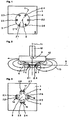
- the Fig. 1 shows in plan view of a sensor according to the invention, which is suitable for example as an angle sensor for the control of a brushless electric motor with three coils.
- the sensor comprises a semiconductor chip 1 with six horizontal Hall elements 2.1 to 2.6 and a single magnetic field concentrator 3.
- the magnetic field concentrator 3 is disk-shaped and the six Hall elements 2 are arranged at regular intervals along the edge 4 of the magnetic field concentrator 3.
- the Hall elements 2.1 to 2.6 are known per se in technology, preferably in CMOS technology as n-well 6 (FIG. Fig. 2 ) in a p-doped substrate 7 (FIG. Fig. 2 ) realized. Horizontal Hall elements are sensitive to the component of the magnetic field which impinges perpendicular to the surface 8 of the semiconductor chip 1.
- the Hall elements 2.1 to 2.6 have a cross-shaped structure whose orientation is preferably parallel to the crystal axis 100, so that the influence of varying mechanical stresses on the Hall signal remains as low as possible.
- the magnetic field concentrator 3 is made of ferromagnetic material, preferably permalloy or mumetal or a metal glass, e.g. available as a tape of about 15 ⁇ m to 30 ⁇ m thickness. Preference is given to a metal glass with a comparatively low coercive force, so that no hysteresis effects occur. In addition, their magnetization is largely isotropic.
- the magnetic field concentrator 3 extends in a plane 9 and has a flat shape, ie its thickness is substantially less than its extent in the plane.
- the magnetic field concentrator 3 preferably has a uniform thickness. But it can be made thicker in the middle than at the edge.
- the magnetic field concentrator 3 therefore acts as a concentrator for the components of the magnetic field which lie in the plane 9.
- the function of the magnetic field concentrator 3 is based on the Fig. 2 explained in more detail.
- the magnetic field concentrator 3 has in this example a center of symmetry 5, namely, it is rotationally symmetrical.
- the Fig. 2 shows the sensor in a section along the line 1-1 of Fig. 1 , and a magnetic field generating permanent magnet 10, for example, mounted on the axis of rotation 11 of a brushless electric motor 12 with three coils.
- the magnetic field concentrator 3 changes in its environment the course of the field lines 13 of the magnetic field and in particular causes the field lines, which would run in the absence of the magnetic field concentrator 3 parallel to the surface 8 of the semiconductor chip 1, the Hall element 2.1 penetrate approximately perpendicular to the surface 8.
- the relative permeability of the material of the magnetic field concentrator 3 is greater than 1000, while the relative permeability of air and the semiconductor substrate 7 is about 1.
- the field lines are therefore virtually always directed perpendicular to the surface of the magnetic field concentrator 3.
- the Hall elements 2.1 to 2.6 are arranged in the region of the lateral edge 4 of the magnetic field concentrator 3, since the vertical component of the magnetic field is greatest there.
- diametrically opposite Hall elements each form a pair for generating an output signal, wherein the Hall voltage of a Hall element is subtracted from the Hall voltage of the other Hall element. Since the field lines penetrate the two Hall elements of a pair in the opposite vertical direction, the voltages resulting from the "deflection" of the magnetic field, while Hall voltages arising for example due to an external, the Hall elements perpendicularly penetrating magnetic interference field, cancel each other out , In addition, technology-related offset voltages are at least partially compensated.
- the Hall elements 2.1 and 2.4 together generate the output signal S 1
- the Hall elements 2.2 and 2.5 generate the output signal S 2
- the Hall elements 2.3 and 2.6 generate the output signal S 3 .
- the strength of the output signals S 1 , S 2 and S 3 depends on the direction of the magnetic field in the plane 9.
- the magnetic field rotates with and generates approximately sinusoidal output signals S 1 , S 2 and S 3 , which are phase-shifted by 120 °.
- the output signal S 1 is always maximum when the direction of the magnetic field of the permanent magnet 10 is parallel to the axis connecting the two Hall elements 2.1 and 2.4
- the output signal S 2 is always maximum when the direction of the magnetic field of the permanent magnet 10 is parallel to the axis connecting the two Hall elements 2.3 and 2.5, etc.
- the output signals S 1 , S 2 and S 3 can, as in the European patent application EP 954085 described, are used to control the three coils of the electric motor 12.
- the output signals S 1 , S 2 and S 3 can also be used to determine the angle of rotation ⁇ of the axis of rotation 11 when the electric motor 12 is stationary.
- the output signals S 1 , S 2 and S 3 are superimposed as possible no signals that do not originate from the magnetic field of the permanent magnet 10.
- the proposed example with the pairwise coupled Hall elements is particularly suitable for this because the influence of external interference fields is largely eliminated and technology-related offset voltages are largely compensated.
- Technology-related offset voltages can be further reduced if instead of the individual Hall elements 2.1 to 2.6 of two or more Hall elements existing groups of Hall elements are used, the current directions in the different Hall elements of a group are different.
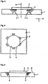
- FIG. 3 Such an example is in the Fig. 3 represented where four groups 14 to 17, each with two Hall elements 2.1 to 2.8 are present. Mutually diametrically opposed groups of Hall elements are coupled in pairs, so that the sensor provides two output signals S 1 and S 2 .
- the Hall elements are cross-shaped and each Hall element is associated with an arrow indicating the direction of current within the Hall element.
- the magnetic field concentrator 3 also has a cross-shaped structure, resulting in a higher concentration of the magnetic field at the location of the Hall elements than the circular structure shown in the previous example.
- This sensor is suitable for example for the control of an electric motor 12 with two coils. If necessary, it is possible to store the value of the output signals S 1 and S 2 as a function of the angle of rotation ⁇ . Since the output signals S 1 and S 2 are phase-shifted, the rotational angle ⁇ can be easily determined unambiguously on the basis of the output signals S 1 and S 2 .
- the Fig. 4 shows, with respect to the sensor of the first example, in a schematic, not true to scale representation of the semiconductor chip 1 with the two integrated Hall elements 2.1 and 2.4, which are diametrically opposed to each other in the plane with respect to the axis of rotation 11 (see also Fig. 1 ) and the circular magnetic field concentrator 3.
- With vertical arrows are the strength and direction of the permanent magnet 10 (FIG. Fig. 2 ) generated field in the region of the two Hall elements 2.1 and 2.4.
- a displacement of the magnetic field concentrator 3 from the ideal position in the positive x-direction causes a decrease in the Hall voltage in the Hall element 2.1 and an increase in the Hall voltage in the Hall element 2.4.
- the diameter of the magnetic field concentrator 3 is matched to the distance of the two Hall elements 2.1 and 2.4, that both Hall elements 2.1 and 2.4, with ideal position of the magnetic field concentrator 3 with respect to the two Hall elements 2.1 and 2.4, not within the zone where the field strength of the magnetic field reaches its maximum: the Hall elements 2.1 and 2.4 are either closer to the center, as in the Fig. 4 shown, or placed more distant from the center. The influence of positioning variations of the magnetic field concentrator 3 with respect to the two Hall elements 2.1 and 2.4 is minimized.
- the sensor is only used to control an electric motor, wherein the rotation angle at the stoppage of the engine is not interested, then it is sufficient if only one of the paired Hall elements is present.
- these are the Hall elements 2.1, 2.2 and 2.3.
- a magnetic field concentrator instead of a circular magnetic field concentrator, a magnetic field concentrator with another, e.g. polygonal shape, to be used. In particular, for photolithographic reasons, it may be appropriate to approximate the circular shape by a polygon. Likewise, the number of Hall elements can be increased.
- the Fig. 5 shows an embodiment with vertical Hall elements 2.
- Vertical Hall elements are sensitive to the component of the magnetic field, which penetrate the Hall element parallel to the surface 8 of the semiconductor chip 1.
- a with the electronics integrable vertical Hall element is for example in the American patent US 5572058 described.
- the vertical Hall elements 2 are aligned tangentially to the edge 4 of the magnetic field concentrator 3. They are in the region of the edge 4 of the magnetic field concentrator 3, but not below the magnetic field concentrator 3 as the horizontal Hall elements, but laterally offset outside the magnetic field concentrator 3, where the parallel to the surface 8 of the semiconductor chip 1 extending field lines 13 (FIG. Fig. 2 ) of the magnetic field are greatest.
- the Fig. 6 shows with arrows the strength of the horizontal field lines 13 (FIG. Fig. 2 ) of the magnetic field in the region of the vertical Hall elements 2, wherein the length of the arrows is proportional to the strength of the magnetic field.
- the sensors described are also suitable as angle sensor for the in the cited European patent application EP 893 668 described applications.
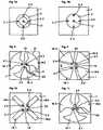
- the Fig. 7a shows an example of a sensor in which the magnetic field concentrator 3 has the shape of a circular ring. This allows the arrangement of a further horizontal Hall element 2 ', for example in the center of the annulus, with which the perpendicular to the Hall element 2' incident component of the magnetic field can be measured.
- a sensor is suitable for use in a joystick, for example, since it allows the direction of an external magnetic field to be determined in three dimensions.
- the magnetic field concentrator 3 Since the magnetic field concentrator 3 is very thin, it practically does not affect the component of the magnetic field which impinges perpendicular to the Hall element 2 '. Also with the in the Fig. 7b The sensor shown can determine the direction of an external magnetic field in three dimensions. However, there is a risk that the vertical component of horizontal components overlap, because the magnetic field concentrator 3 amplified the horizontal components and secondly in deviations of the magnetic field concentrator 3 from its desired position and horizontal components of the magnetic field, the Hall element 2 'could penetrate in the vertical direction ,
- the magnetic field concentrator 3 can also act as a concentrator for the vertical component of the magnetic field, namely when the width of the ferromagnetic annulus is comparable to its thickness. From the sum of the signals of the two Hall elements 2.1 and 2.3 or the sum of the signals of the two Hall elements 2.2 and 2.4, a signal can be obtained which is proportional to the vertical component of the magnetic field, while from the differences, as stated above, the horizontal components of the magnetic field. The Hall element 2 'can then be omitted.
- a single Hall element occupies a relatively small area of typically several tens * tens of microns.
- the diameter of the circular magnetic field concentrator is about 0.2 mm to 0.5 mm. Ideally, the diameter of the magnetic field concentrator is less than the diameter of the permanent magnet, which is typically 1.3 mm or more.
- an external field above 20 mT leads to saturation effects in the magnetic field concentrator. If the desired distance between the permanent magnet and the sensor is selected such that the magnetic field concentrator is at least partially magnetically saturated, then this has the advantage that the output signals S 1 , S 2 , etc. are not or only slightly offset by distance fluctuations of the permanent magnet Suspend the sensor.
- Hall elements it is also possible to operate the Hall elements as a pulse, wherein the rotating permanent magnet per revolution generates as many pulses as Hall elements are present.
- the Fig. 8 shows an angle sensor with three magnetic field concentrators 18.1, 18.2 and 18.3, which is like the sensor of the first example together with an acting as an angle sensor permanent magnet as an angle sensor for controlling a three coils having electric motor.
- the magnetic field concentrators 18.1, 18.2 and 18.3 are arranged symmetrically with respect to a point of symmetry 19, namely with a 120 ° rotational symmetry. In the region of the edge 4 of each magnetic field concentrator facing the point of symmetry 19, there is a horizontal Hall element 2.1, 2.2 or 2.3.
- the edge 4 of the magnetic field concentrators is subdivided into two regions, namely an inner region where opposing edges 20 of the magnetic field concentrators 18.1, 18.2 and 18.3 run parallel so that the density of the magnetic field lines in the gap between the two edges 20 is as homogeneous as possible and one Saturation of the peaks is avoided, and an outer area, where the distance between adjacent magnetic field concentrators is much larger, to avoid that the magnetic field is "shorted" here.
- the outer edge 21 of the magnetic field concentrators 18.1, 18.2 and 18.3 extends over as large an angular range as possible to focus the outer magnetic field as efficiently as possible in the Hall elements 2.1, 2.2 and 2.3 and to avoid saturation peaks, which influence the angular dependence of the signals.
- each Hall element 2.1, 2.2 or 2.3 provides an output signal S 1 S 2 or S 3 .
- FIGS. 9 and 10 show two more sensors with four magnetic field concentrators 18.1 to 18.4, with which The direction of a magnetic field can be determined in two spatial dimensions.
- two mutually diametrically opposite Hall elements are each coupled to a pair with respect to the point of symmetry 19: the Hall elements 2.1 and 2.3 together generate the output signal S 1 , the Hall elements 2.2 and 2.4 together generate the output signal S 2 . From the output signals S 1 and S 2 , the direction of the magnetic field in the plane 9 of the sensor can be determined.
- the magnetic field concentrators need not be flat. They can be made thicker against the edge or coupled to additional external magnetic field concentrators in order to concentrate the magnetic field in the region of the Hall elements as efficiently as possible.
- the Fig. 11 shows an embodiment with three magnetic field concentrators 18.1, 18.2, 18.3 and three vertical Hall elements 2.1, 2.2, 2.3, which are each arranged in the middle between the parallel edges 20 of adjacent magnetic field concentrators 18.1, 18.2, 18.3.
Landscapes
- Physics & Mathematics (AREA)
- General Physics & Mathematics (AREA)
- Condensed Matter Physics & Semiconductors (AREA)
- Transmission And Conversion Of Sensor Element Output (AREA)
- Measuring Magnetic Variables (AREA)
- Hall/Mr Elements (AREA)
- Brushless Motors (AREA)
- Measurement Of Length, Angles, Or The Like Using Electric Or Magnetic Means (AREA)
- Geophysics And Detection Of Objects (AREA)
- Switches That Are Operated By Magnetic Or Electric Fields (AREA)
Description
- Die Erfindung betrifft einen Sensor für die Detektion der Richtung eines Magnetfeldes der im Oberbegriff dem Anspruches 1 und 2 genannten Art.
- Ein solcher Sensor eignet sich beispielsweise als Winkelsensor für die Steuerung bürstenloser Elektromotoren, die einen aus mehreren Spulen bestehenden Stator aufweisen. Der Rotor des Elektromotors weist einen Permanentmagneten auf, der mit dem Sensor zusammenwirkt zur Erzeugung eines vom Drehwinkel abhängigen Signals für die phasengerechte Ansteuerung der Spulen. Eine solche Anordnung ist aus der europäischen Patentanmeldung
EP 954 085 - Bekannt ist auch die Verwendung horizontaler Hallelemente, die empfindlich auf die senkrecht auf die Chipoberfläche auftreffende Komponente des vom Permanentmagneten erzeugten Magnetfeldes sind. Diese Hallelemente sind zwar mit der Verarbeitungselektronik auf demselben Chip integrierbar. Aber dieser Lösung haftet der Nachteil an, dass die Hallelemente im Bereich des Randes des Permanentmagneten angeordnet sein müssen, wo die vertikale Komponente des Magnetfeldes am grössten ist. Im Bereich der Drehachse ist die vertikale Komponente nämlich klein. Die Plazierung der Hallelemente ist abhängig von den Abmessungen des Permanentmagneten. Bei grösseren Permanentmagneten ist es dann nicht mehr wirtschaftlich, die Hallelemente auf einem einzigen Halbleiterchip zu integrieren.
- Aus der europäischen Patentanmeldung
EP 893 668 - Aus der europäischen Patentanmeldung
EP 772 046 - Aus dem Patent
US 6 084 401 ist ein Winkelsensor bekannt, der einen scheibenförmigen Magnetfeldkonzentrator und eine Vielzahl von magnetoresistiven Magnetfeldsensoren umfasst, die entlang eines Kreises um den Magnetfeldkonzentrator herum angeordnet sind. Der Magnetfeldkonzentrator wirkt mit einem als Winkelgeber eingesetzten Magneten zusammen, um ein Magnetfeld zu erzeugen, das im Bereich der Magnetfeldsensoren tangential zu den Magnetfeldsensoren und damit in deren Empfindlichkeitsrichtung verläuft. - Aus der deutschen Patentanmeldung
DE 199 56 361 ist ein magnetischer Drehwinkelsensor bekannt, bei dem in einer senkrecht zur Drehachse verlaufenden Ebene eine Vielzahl von gleichartigen Magnetfeldkonzentratoren und in den Lücken zwischen den Magnetfeldkonzentratoren magnetoresistive Magnetfeldsensoren angeordnet sind. - Aus dem Patent
US 5 880 586 ist ein Winkelsensor bekannt, bei dem zwei Hallelemente eingesetzt werden, um zwei Komponenten des von einem Winkelgeber erzeugten Magnetfelds zu messen. - Der Erfindung liegt die Aufgabe zugrunde, einen Sensor vorzuschlagen, der die eingangs erwähnten Nachteile nicht mehr aufweist.
- Die Erfindung besteht in den im Anspruch 1 angegebenen Merkmalen. Vorteilhafte Ausgestaltungen ergeben sich aus den abhängigen Ansprüchen.
- Gemäss einem ersten Aspekt der Erfindung umfasst ein Sensor für die Detektion der Richtung eines Magnetfeldes einen einzigen Magnetfeldkonzentrator mit einer flächigen Form und mindestens ein erstes Hallelement und ein zweites Hallelement oder mindestens eine erste Gruppe und eine zweite Gruppe von Hallelementen, wobei die Hallelemente im Bereich des Randes des Magnetfeldkonzentrators angeordnet sind.
- Der flächige Magnetfeldkonzentrator hat die Aufgabe, ein externes Magnetfeld derart zu beeinflussen, dass es die Hallelemente in optimaler Weise durchflutet.
- Die Hallelemente können sogenannte horizontale Hallelemente oder sogenannte vertikale Hallelemente sein. Horizontale Hallelemente sind empfindlich auf die Komponente des Magnetfeldes, die senkrecht auf ihre Oberfläche auftrifft, während vertikale Hallelemente empfindlich sind auf eine Komponente des Magnetfeldes, die parallel zu ihrer Oberfläche verläuft. Horizontale Hallelemente sind demzufolge unterhalb des Magnetfeldkonzentrators, vertikale Hallelemente im Bereich neben dem Rand, ausserhalb des Magnetfeldkonzentrators anzuordnen.
- Gemäss einem anderen Aspekt umfasst ein Sensor für die Detektion der Richtung eines Magnetfeldes mindestens drei in einer Ebene, bezüglich eines Symmetriepunktes symmetrisch angeordnete Magnetfeldkonzentratoren, die im Bereich des Symmetriepunktes einander zugewandte Kanten aufweisen, die parallel zueinander verlaufen, und pro Magnetfeldkonzentrator ein Hallelement oder eine Gruppe von Hallelementen, wobei die Hallelemente im Bereich der parallel verlaufenden Kanten des Randes des zugehörigen Magnetfeldkonzentrators angeordnet sind.
- Nachfolgend werden Ausführungsbeispiele der anhand der Zeichnung näher erläutert.
- Es zeigen:
- Fig. 1,
- ein erstes Beispiel eines erfindungsgemässen Sensors mit horizontalen Hall- elementen,
- Fig. 2
- den Sensor in einem Schnitt entlang der Linie 1-1 in
Fig. 1 , - Fig. 3
- ein zweites Beispiel eines erfindungsgemässen Sensors,
- Fig. 4
- Details des Sensors,
- Fig. 5, 6
- ein Beispiel eines erfindungsgemässen Sensors mit vertikalen Hallelementen,
- Fig. 7a, b
- Sensoren, mit denen sich die Richtung eines äusseren Magnetfeldes in drei Dimensionen bestimmen lässt, und
- Fig. 8-11
- weitere Sensoren.
- Die
Fig. 1 zeigt in Aufsicht einen erfindungsgemässen Sensor, der sich z.B. als Winkelsensor für die Steuerung eines bürstenlosen Elektromotors mit drei Spulen eignet. Der Sensor umfasst einen Halbleiterchip 1 mit sechs horizontalen Hallelementen 2.1 bis 2.6 und einen einzigen Magnetfeldkonzentrator 3. Bei diesem ersten Beispiel ist der Magnetfeldkonzentrator 3 scheibenförmig ausgebildet und die sechs Hallelemente 2 sind in gleichmässigen Abständen verteilt entlang des Randes 4 des Magnetfeldkonzentrators 3 angeordnet. - Die Hallelemente 2.1 bis 2.6 sind in an sich bekannter Technologie, vorzugsweise in CMOS Technologie als n-Wanne 6 (
Fig. 2 ) in einem p-dotierten Substrat 7 (Fig. 2 ) realisiert. Horizontale Hallelemente sind empfindlich auf die Komponente des Magnetfeldes, die senkrecht auf die Oberfläche 8 des Halbleiterchips 1 auftrifft. Im Beispiel haben die Hallelemente 2.1 bis 2.6 eine kreuzförmige Struktur, deren Ausrichtung vorzugsweise parallel zur 100 Kristallachse ist, damit der Einfluss veränderlicher mechanischer Spannungen auf das Hallsignal möglichst gering bleibt. - Der Magnetfeldkonzentrator 3 besteht aus ferromagnetischem Material, vorzugsweise aus Permalloy oder Mumetall oder einem Metallglas, die z.B. als Band von etwa 15µm bis 30µm Dicke erhältlich sind. Bevorzugt wird ein Metallglas mit einer vergleichsweise geringen Koerzitivfeldstärke, damit keine Hystereseeffekte auftreten. Zudem ist deren Magnetisierung weitgehend isotrop.
- Der Magnetfeldkonzentrator 3 erstreckt sich in einer Ebene 9 und hat eine flächige Form, d.h. seine Dicke ist wesentlich geringer als seine Ausdehnung in der Ebene. Der Magnetfeldkonzentrator 3 weist vorzugsweise eine gleichmässige Dicke auf. Er kann aber in der Mitte dicker als am Rand ausgebildet sein. Der Magnetfeldkonzentrator 3 wirkt daher als Konzentrator für die Komponenten des Magnetfeldes, die in der Ebene 9 liegen. Die Funktion des Magnetfeldkonzentrators 3 wird anhand der
Fig. 2 näher erläutert. Der Magnetfeldkonzentrator 3 weist bei diesem Beispiel ein Symmetriezentrum 5 auf, er ist nämlich rotationssymmetrisch. - Die
Fig. 2 zeigt den Sensor in einem Schnitt entlang der Linie 1-1 derFig. 1 , sowie einen ein Magnetfeld erzeugenden Permanentmagneten 10, der z.B. auf der Drehachse 11 eines bürstenlosen Elektromotors 12 mit drei Spulen angebracht ist. Der Magnetfeldkonzentrator 3 verändert in seinem Umfeld den Verlauf der Feldlinien 13 des Magnetfeldes und bewirkt insbesondere, dass die Feldlinien, die bei Abwesenheit des Magnetfeldkonzentrators 3 parallel zur Oberfläche 8 des Halbleiterchips 1 verlaufen würden, das Hallelement 2.1 annähernd senkrecht zur Oberfläche 8 durchdringen. Die relative Permeabilität des Materials des Magnetfeldkonzentrators 3 ist grösser als 1000, während die relative Permeabilität von Luft und vom Halbleitersubstrat 7 etwa 1 beträgt. Die Feldlinien sind daher praktisch immer senkrecht zur Oberfläche des Magnetfeldkonzentrators 3 gerichtet. Die Hallelemente 2.1 bis 2.6 sind im Bereich des seitlichen Randes 4 des Magnetfeldkonzentrators 3 angeordnet, da die vertikale Komponente des Magnetfeldes dort am grössten ist. - Einander bezüglich des Symmetriezentrums 5 (
Fig. 1 ) diametral gegenüberliegende Hallelemente bilden je ein Paar zur Erzeugung eines Ausgangssignals, wobei die Hallspannung des einen Hallelementes von der Hallspannung des anderen Hallelementes subtrahiert wird. Da die Feldlinien die beiden Hallelemente eines Paares in entgegengesetzter vertikaler Richtung durchdringen, addieren sich die Spannungen, die durch die "Umlenkung" des Magnetfeldes entstehen, während sich Hallspannungen, die beispielsweise aufgrund eines äusseren, die Hallelemente senkrecht durchdringenden magnetischen Störfeldes entstehen, sich gegenseitig aufheben. Zudem werden technologiebedingte Offsetspannungen mindestens teilweise kompensiert. Die Hallelemente 2.1 und 2.4 erzeugen also gemeinsam das Ausgangssignal S1, die Hallelemente 2.2 und 2.5 erzeugen das Ausgangssignal S2 und die Hallelemente 2.3 und 2.6 erzeugen das Ausgangssignal S3. Die Stärke der Ausgangssignale S1, S2 und S3 hängt ab von der Richtung des Magnetfeldes in der Ebene 9. - Wenn der Permanentmagnet 10 um die Drehachse 11 rotiert, dann rotiert das Magnetfeld mit und erzeugt etwa sinusförmige Ausgangssignale S1, S2 und S3, die um 120° phasenverschoben sind. Das Ausgangssignal S1 ist immer dann maximal, wenn die Richtung des Magnetfeldes des Permanentmagneten 10 parallel zur Achse ist, die die beiden Hallelemente 2.1 und 2.4 verbindet, das Ausgangssignal S2 ist immer dann maximal, wenn die Richtung des Magnetfeldes des Permanentmagneten 10 parallel zur Achse ist, die die beiden Hallelemente 2.3 und 2.5 verbindet, etc. Die Ausgangssignale S1, S2 und S3 können wie in der europäischen Patentanmeldung
EP 954085 - Die Ausgangssignale S1, S2 und S3 können aber auch zur Bestimmung des Drehwinkels ϕ der Drehachse 11 benutzt werden, wenn der Elektromotor 12 stillsteht. Hier kommt es darauf an, dass den Ausgangssignalen S1, S2 und S3 möglichst keine Signale überlagert sind, die nicht vom Magnetfeld des Permanentmagneten 10 stammen. Das vorgeschlagene Beispiel mit den jeweils paarweise gekoppelten Hallelementen eignet sich hierzu besonders, da der Einfluss externer Störfelder weitgehend eliminiert und technologiebedingte Offsetspannungen weitgehend kompensiert sind. Technologiebedingte Offsetspannungen können weiter reduziert werden, wenn anstelle der einzelnen Hallelemente 2.1 bis 2.6 aus zwei oder mehreren Hallelementen bestehende Gruppen von Hallelementen verwendet werden, wobei die Stromrichtungen in den verschiedenen Hallelementen einer Gruppe unterschiedlich sind.
- Ein solches Beispiel ist in der
Fig. 3 dargestellt, wo vier Gruppen 14 bis 17 mit je zwei Hallelementen 2.1 bis 2.8 vorhanden sind. Einander diametral gegenüberliegende Gruppen von Hallelementen werden paarweise gekoppelt, so dass der Sensor zwei Ausgangssignale S1 und S2 liefert. D.h. also, dass aus den Hallspannungen der Hallelemente 2.1, 2.2, 2.5, und 2.6 das Ausgangssignal S1 gebildet und aus den Hallspannungen der Hallelemente 2.3, 2.4, 2.7 und 2.8 das Ausgangssignal S2 gebildet wird. In derFig. 3 sind die Hallelemente kreuzförmig und jedem Hallelement ist ein Pfeil zugeordnet, der die Stromrichtung innerhalb des Hallelementes anzeigt. Bei diesem Beispiel weist der Magnetfeldkonzentrator 3 ebenfalls eine kreuzförmige Struktur auf, was zu einer gegenüber der im vorhergehenden Beispiel gezeigten kreisförmigen Struktur höheren Konzentration des Magnetfeldes am Ort der Hallelemente führt. Dieser Sensor eignet sich z.B. für die Steuerung eines Elektromotors 12 mit zwei Spulen. Bei Bedarf ist es möglich, den Wert der Ausgangssignale S1 und S2 in Funktion des Drehwinkels ϕ zu speichern. Da die Ausgangssignale S1 und S2 phasenverschoben sind, lässt sich der Drehwinkel ϕ anhand der Ausgangssignale S1 und S2 problemlos eindeutig bestimmen. - Die
Fig. 4 zeigt, bezogen auf den Sensor des ersten Beispiels, in schematischer, nicht massstabsgetreuer Darstellung den Halbleiterchip 1 mit den beiden integrierten Hallelementen 2.1 und 2.4, die einander in der Ebene bezüglich der Drehachse 11 diametral gegenüberliegen (siehe auchFig. 1 ), und den kreisförmigen Magnetfeldkonzentrator 3. Mit vertikalen Pfeilen sind die Stärke und Richtung des vom Permanentmagneten 10 (Fig. 2 ) erzeugten Feldes im Bereich der beiden Hallelemente 2.1 und 2.4 dargestellt. Eine Verschiebung des Magnetfeldkonzentrators 3 aus der idealen Position in positiver x-Richtung bewirkt eine Abnahme der Hallspannung im Hallelement 2.1 und eine Zunahme der Hallspannung im Hallelement 2.4. Vorteilhafterweise ist der Durchmesser des Magnetfeldkonzentrators 3 so auf den Abstand der beiden Hallelemente 2.1 und 2.4 abgestimmt, dass sich beide Hallelemente 2.1 und 2.4, bei idealer Lage des Magnetfeldkonzentrators 3 bezüglich der beiden Hallelemente 2.1 und 2.4, nicht innerhalb der Zone befinden, wo die Feldstärke des Magnetfeldes ihr Maximum erreicht: Die Hallelemente 2.1 und 2.4 sind entweder näher beim Zentrum, wie in derFig. 4 gezeigt, oder entfernter vom Zentrum plaziert. Der Einfluss von Positionierungsvariationen des Magnetfeldkonzentrators 3 bezüglich der beiden Hallelemente 2.1 und 2.4 wird so minimiert. - Falls der Sensor nur zur Steuerung eines Elektromotors dient, wobei der Drehwinkel im Stillstand des Motors nicht interessiert, dann genügt es, wenn nur eines der paarweise gekoppelten Hallelemente vorhanden ist. Beim ersten Ausführungsbeispiel sind dies die Hallelemente 2.1, 2.2 und 2.3.
- Anstelle eines kreisförmigen Magnetfeldkonzentrators kann auch ein Magnetfeldkonzentrator mit einer anderen, z.B. polygonalen Form, verwendet werden. Insbesondere aus photolithographischen Gründen kann es angezeigt sein, die Kreisform durch ein Vieleck anzunähern. Ebenso kann die Zahl der Hallelemente erhöht werden.
- Die
Fig. 5 zeigt ein Ausführungsbeispiel mit vertikalen Hallelementen 2. Vertikale Hallelemente sind empfindlich auf die Komponente des Magnetfeldes, die das Hallelement parallel zur Oberfläche 8 des Halbleiterchips 1 durchdringen. Ein mit der Elektronik integrierbares vertikales Hallelement ist beispielsweise im amerikanischen PatentUS 5572058 beschrieben. Die vertikalen Hallelemente 2 sind tangential zum Rand 4 des Magnetfeldkonzentrators 3 ausgerichtet. Sie befinden sich im Bereich des Randes 4 des Magnetfeldkonzentrators 3, aber nicht unterhalb des Magnetfeldkonzentrators 3 wie die horizontalen Hallelemente, sondern seitlich versetzt ausserhalb des Magnetfeldkonzentrators 3, wo die parallel zur Oberfläche 8 des Halbleiterchips 1 verlaufenden Feldlinien 13 (Fig. 2 ) des Magnetfeldes am grössten sind. - Die
Fig. 6 zeigt mit Pfeilen die Stärke der horizontal verlaufenden Feldlinien 13 (Fig. 2 ) des Magnetfeldes im Bereich der vertikalen Hallelemente 2, wobei die Länge der Pfeile proportional zur Stärke des Magnetfeldes ist. - Die Vorteile dieser Lösungen gegenüber den aus dem Stand der Technik bekannten Lösungen liegen darin, dass
- a) die Position der Hallelemente bezüglich des Permanentmagneten unkritisch ist, da die Hallelemente nicht im Bereich des Randes des Permanentmagneten plaziert werden müssen, wo die vertikale Komponente des Magnetfeldes am grössten ist, sondern im Bereich der Drehachse, wo die horizontalen Komponenten am grössten sind, so dass die Plazierung des Halbleiterchips, in dem die Hallelemente integriert sind, unabhängig von der Lage des Randes des Permanentmagneten erfolgen kann.
- b) der Magnetfeldkonzentrator das Magnetfeld im Bereich der Hallelemente zusätzlich verstärkt,
- c) die Hallelemente und die Verarbeitungselektronik auf dem gleichen Halbleiterchip integrierbar sind, und
- d) eine in den üblichen Fertigungstoleranzen liegende Abweichung der Ist-Lage des Magnetfeldkonzentrators von seiner Soll-Lage kaum Einfluss auf die erzeugten Signale hat.
- Die beschriebenen Sensoren eignen sich auch als Winkelsensor für die in der eingangs zitierten europäischen Patentanmeldung
EP 893 668 - Die
Fig. 7a zeigt ein Beispiel eines Sensors, bei dem der Magnetfeldkonzentrator 3 die Form eines Kreisringes aufweist. Dies erlaubt die Anordnung eines weiteren horizontalen Hallelementes 2', beispielsweise im Zentrum des Kreisringes, mit dem die senkrecht auf das Hallelement 2' auftreffende Komponente des Magnetfeldes gemessen werden kann. Ein solcher Sensor eignet sich z.B. für die Verwendung in einem Joystick, da sich damit die Richtung eines äusseren Magnetfeldes in drei Dimensionen bestimmen lässt. - Da der Magnetfeldkonzentrator 3 sehr dünn ist, beeinflusst er die senkrecht auf das Hallelement 2' auftreffende Komponente des Magnetfeldes praktisch nicht. Auch mit dem in der
Fig. 7b dargestellten Sensor lässt sich die Richtung eines äusseren Magnetfeldes in drei Dimensionen bestimmen. Allerdings besteht hier die Gefahr, dass sich der vertikalen Komponente horizontale Komponenten überlagern, weil der Magnetfeldkonzentrator 3 erstens die horizontalen Komponenten verstärkt und zweitens bei Abweichungen des Magnetfeldkonzentrators 3 von seiner Soll-Lage auch horizontale Komponenten des Magnetfeldes das Hallelement 2' in senkrechter Richtung durchdringen könnten. - Anzumerken ist jedoch, dass beim Beispiel nach
Fig. 7a der Magnetfeldkonzentrator 3 auch für die vertikale Komponente des Magnetfeldes als Konzentrator wirken kann, nämlich dann, wenn die Breite des ferromagnetischen Kreisringes vergleichbar mit seiner Dicke ist. Aus der Summe der Signale der beiden Hallelemente 2.1 und 2.3 oder der Summe der Signale der beiden Hallelemente 2.2 und 2.4 lässt sich ein Signal gewinnen, das proportional zur vertikalen Komponente des Magnetfeldes ist, während sich aus den Differenzen, wie oben dargelegt, die horizontalen Komponenten des Magnetfeldes bestimmen lassen. Das Hallelement 2' kann dann sogar entfallen. - Ein einzelnes Hallelement beansprucht eine relativ kleine Fläche von typischerweise einigen zehn * einigen zehn Mikrometern. Der Durchmesser des kreisförmigen Magnetfeldkonzentrators beträgt etwa 0.2 mm bis 0.5 mm. Im Idealfall ist der Durchmesser des Magnet-feldkonzentrators geringer als der Durchmesser des Permanentmagneten, der typischerweise 1.3 mm oder mehr beträgt.
- Typischerweise führt ein äusseres Feld ab 20 mT im Magnetfeldkonzentrator zu Sättigungseffekten. Wenn der Soll-Abstand zwischen dem Permanentmagneten und dem Sensor so gewählt wird, dass der Magnetfeldkonzentrator mindestens teilweise magnetisch gesättigt ist, dann hat dies den Vorteil, dass die Ausgangssignale S1, S2, etc. nicht oder nur wenig von Abstandsschwankungen des Permanentmagneten vom Sensor abhängen.
- Es ist auch möglich, die Hallelemente als Impulsgeber zu betreiben, wobei der rotierende Permanentmagnet pro Umdrehung so viele Impulse erzeugt, wie Hallelemente vorhanden sind.
- Die
Fig. 8 zeigt einen Winkelsensor mit drei Magnetfeldkonzentratoren 18.1, 18.2 und 18.3, der sich wie der Sensor des ersten Beispiels zusammen mit einem als Winkelgeber wirkenden Permanentmagneten als Winkelsensor zur Steuerung eines drei Spulen aufweisenden Elektromotors eignet. Die Magnetfeldkonzentratoren 18.1, 18.2 und 18.3 sind symmetrisch bezüglich eines Symmetriepunktes 19 angeordnet, nämlich mit einer 120° Rotationssymmetrie. Im Bereich des dem Symmetriepunkt 19 zugewandten Randes 4 eines jeden Magnetfeldkonzentrators befindet sich ein horizontales Hallelement 2.1, 2.2 bzw. 2.3. Der Rand 4 der Magnetfeldkonzentratoren ist unterteilt in zwei Bereiche, nämlich einen inneren Bereich, wo einander gegenüberliegende Kanten 20 der Magnetfeldkonzentratoren 18.1, 18.2 und 18.3 parallel verlaufen, damit die Dichte der Feldlinien des Magnetfeldes im Spalt zwischen den beiden Kanten 20 möglichst homogen ist und eine Sättigung der Spitzen vermieden wird, und einen äusseren Bereich, wo der Abstand zwischen benachbarten Magnetfeldkonzentratoren viel grösser ist, um zu vermeiden, dass das Magnetfeld hier "kurzgeschlossen" wird. Der äussere Rand 21 der Magnetfeldkonzentratoren 18.1, 18.2 und 18.3 erstreckt sich über einen möglichst grossen Winkelbereich, um das äussere Magnetfeld möglichst effizient im Bereich der Hallelemente 2.1, 2.2 bzw. 2.3 zu konzentrieren und um Sättigungsspitzen zu vermeiden, welche die Winkelabhängigkeit der Signale beeinflussen. Bei diesem Beispiel liefert jedes Hallelement 2.1, 2.2 bzw. 2.3 ein Ausgangssignal S1 S2 bzw. S3. - Anstelle der einzelnen Hallelemente 2.1, 2.2 bzw. 2.3 können auch Gruppen von Hallelementen vorgesehen sein, die untereinander bereits offsetkorrigiert sind.
- Die
Fig. 9 und 10 zeigen zwei weitere Sensoren mit vier Magnetfeldkonzentratoren 18.1 bis 18.4, mit denen sich die Richtung eines Magnetfeldes in zwei räumlichen Dimensionen bestimmen lassen. Hier sind je zwei einander bezüglich des Symmetriepunktes 19 diametral gegenüberliegende Hallelemente zu einem Paar gekoppelt: Die Hallelemente 2.1 und 2.3 erzeugen gemeinsam das Ausgangssignal S1, die Hallelemente 2.2 und 2.4 erzeugen gemeinsam das Ausgangssignal S2. Aus den Ausgangssignalen S1 und S2 lässt sich die Richtung des Magnetfeldes in der Ebene 9 des Sensors bestimmen. - Bei den in den
Fig. 8 bis 10 gezeigten Sensoren müssen die Magnetfeldkonzentratoren nicht flächig ausgebildet sein. Sie können gegen den Rand dicker ausgebildet oder an zusätzliche externe Magnetfeldkonzentratoren angekoppelt sein, um das Magnetfeld im Bereich der Hallelemente möglichst effizient zu konzentrieren. - Die
Fig. 11 zeigt ein Ausführungsbeispiel mit drei Magnetfeldkonzentratoren 18.1, 18.2, 18.3 und drei vertikalen Hallelementen 2.1, 2.2, 2.3, die jeweils in der Mitte zwischen den parallel verlaufenden Kanten 20 benachbarter Magnetfeldkonzentratoren 18.1, 18.2, 18.3 angeordnet sind. - Während Ausführungsbeispiele und Anwendungen dieser Erfindung gezeigt und beschrieben wurden, ist es für die Fachleute offenbar, dass im Lichte dieser Ausführungen viele weitere Modifikationen als die vorgängig erläuterten möglich sind, ohne vom erfinderischen Konzept abzuweichen. Die Erfindung ist daher nicht einzuschränken, ausgenommen im Sinne der Ansprüche.
Claims (4)
- Sensor für die Detektion der Richtung eines Magnetfeldes, umfassend:- einen Halbleiterchip (1),- mindestens ein erstes Hallelement (2.1) und ein zweites Hallelement (2.2) oder mindestens eine erste Gruppe (14) von Hallelementen (2.1, 2.2) und eine zweite Gruppe (15) von Hallelementen (2.3, 2.4), und- einen einzigen, auf einer Oberfläche (8) des Halbleiterchips (1) angeordneten scheibenförmigen Magnetfeldkonzentrator (3) mit einer flächigen Form und einem Symmetriezentrum (5), wobei der Magnetfeldkonzentrator (3) aus ferromagnetischen Material besteht unddie Hallelemente horizontale Hallelemente sind, die an der genannten Oberfläche (8) im Halbleiterchip (1) integriert und im Bereich des Randes (4) des Magnetfeldkonzentrators (3) unterhalb des Magnetfeldkonzentrators (3) auf der dem Symmetriezentrum (5) des Magnetfeldkonzentrators (3) zugewandten Seite des Randes (4) des Magnetfeldkonzentrators (3) angeordnet sind, wo sie von Feldlinien des Magnetfelds durchflutet werden, die im Bereich des Randes des Magnelfeldkonzentrators annähernd senkrecht zu der genannten Oberfläche des Halbleiterchips (1) verlaufen, so dass Feldlinien des Magnetfelds, die bei Abwesenheit des Magnetfeldkonzentrators (3) parallel zu der genannten Oberfläche (8) des Halbleiterchips (1) verlaufen würden, die Hallelemente (2) annähernd senkrecht zu der genannten Oberfläche (8) des Halbleiterchips (1) durchdringen, wobeiein drittes Hallelement (2.3) und ein viertes Hallelement (2.4) oder eine dritte Gruppe (16) von Hallelementen (2.5, 2.6) und eine vierte Gruppe (1.7) von Hallelementen (2.7, 2.8) vorhanden sind, wobei die Hallelemente im Bereich des Randes (4) des Magnetfeldkonzentrators (3) angeordnet sind,
dass das erste Hallelement (2.1) und das dritte Hallelement (2.3) bzw. die erste Gruppe (14) von Hallelementen (2.1, 2.2) und die dritte Gruppe (16) von Hallelementen (2.5, 2.6) symmetrisch bezüglich des Symmetriezentrums (5) angeordnet sind und
dass die Hallspannung des ersten Hallelements (2.1) von der Hallspannung des dritten Hallelements (2.3) bzw. die Hallspannungen der ersten Gruppe (14) von Hallelementen (2.1, 2.2) von den Hallspannungen der dritten Gruppe (16) von Hallelementen (2.5, 2.6) subtrahiert wird, und
dass das zweite Hallelement (2.2) und das vierte Hallelement (2.4) bzw. die zweite Gruppe (15) von Hallelementen (2.3, 2.4) und die vierte Gruppe (17) von Hallelementen (2.7, 2.8) symmetrisch bezüglich des Symmetriezentrums (5) angeordnet sind und
dass die Hallspannung des zweiten Hallelements (2.2) von der Hallspannung des vierten Hallelements (2.4) bzw. die Hallspannungen der zweiten Gruppe (15) von Hallelementen (2.3, 2.4) von den Hallspannungen der vierten Gruppe (17) von Hallelementen (2.7, 2.8) subtrahiert wird. - Sensor für die Detektion der Richtung eines Magnetfeldes, umfassend:- einen Halbleiterchip (1),- mindestens ein erstes Hallelement (2.1) und ein zweites Hallelement (2.2) oder mindestens eine erste Gruppe (14) von Hallelementen (2,1, 2.2) und eine zweite Gruppe (15) von Hallelementen (2.3, 2.4), und- einen einzigen, auf einer Oberfläche (8) des Halbleiterchips (1) angeordneten Magnetfeldkonzentrator (3) mit einer flächigen Form, wobei der Magnetfeldkonzentrator (3) aus ferromagnetischen Material besteht und als Konzentrator für diejenigen Komponenten des Magnetfeldes wirkt, die parallel zur genannten Oberfläche (8) des Halbleiterchips (1) verlaufen, undwobei die Hallelemente vertikale Hallelemente sind die an der genannten Oberfläche (8) im Halbleiterchip (1) integriert und im Bereich des Randes (4) des Magnetfeldkonzentrators (3) ausserhalb des Randes (4) des Magnetfeldkonzentrators (3) angeordnet sind, wo sie von Feldlinien des Magnetfelds durchflutet werden, die im Bereich des Randes des Magnetfeldkonzentrators annähernd senkrecht zu der genannten Oberfläche (8) des Halbleiterchips (1) und im Bereich der Hallelemente annähernd parallel zu der genannten Oberfläche (8) des Halbleiterchips (1) verlaufen.
- Sensor nach einem der Ansprüche 1 und 2, dadurch gekennzeichnet, dass der Magnetfeldkonzentrator (3) aus Metallglas ist.
- Verwendung eines Sensors nach einem der Ansprüche 1 bis 3 als Winkelsensor zur Bestimmung der Drehlage eines um eine Drehachse (11) drehbaren Objektes, wobei auf der Drehachse (11) ein Permanentmagnet (10) befestigt ist, dadurch gekennzeichnet, dass
der Abstand zwischen dem Sensor und dem Permanentmagneten (10) so gewählt ist, dass der Magnetfeldkonzentrator (3) magnetisch mindestens teilweise in Sättigung ist.
Applications Claiming Priority (2)
| Application Number | Priority Date | Filing Date | Title |
|---|---|---|---|
| CH20001645 | 2000-08-21 | ||
| CH16452000 | 2000-08-21 |
Publications (5)
| Publication Number | Publication Date |
|---|---|
| EP1182461A2 EP1182461A2 (de) | 2002-02-27 |
| EP1182461A3 EP1182461A3 (de) | 2009-01-21 |
| EP1182461B1 EP1182461B1 (de) | 2010-04-28 |
| EP1182461B8 EP1182461B8 (de) | 2010-06-16 |
| EP1182461B2 true EP1182461B2 (de) | 2019-10-09 |
Family
ID=4565749
Family Applications (1)
| Application Number | Title | Priority Date | Filing Date |
|---|---|---|---|
| EP01202840.3A Expired - Lifetime EP1182461B2 (de) | 2000-08-21 | 2001-07-24 | Sensor für die Detektion der Richtung eines Magnetfeldes |
Country Status (11)
| Country | Link |
|---|---|
| US (1) | US6545462B2 (de) |
| EP (1) | EP1182461B2 (de) |
| JP (1) | JP4936299B2 (de) |
| KR (1) | KR100810784B1 (de) |
| CN (1) | CN1303430C (de) |
| AT (1) | ATE466293T1 (de) |
| BR (1) | BR0103428B1 (de) |
| CA (1) | CA2355682C (de) |
| DE (1) | DE50115458D1 (de) |
| MX (1) | MXPA01008406A (de) |
| TW (1) | TW544525B (de) |
Families Citing this family (275)
| Publication number | Priority date | Publication date | Assignee | Title |
|---|---|---|---|---|
| JP2002039712A (ja) * | 2000-07-27 | 2002-02-06 | Mikuni Corp | 非接触式ロータリセンサと回動軸との結合構造 |
| EP1260825A1 (de) * | 2001-05-25 | 2002-11-27 | Sentron Ag | Magnetfeldsensor |
| CN1330939C (zh) * | 2002-03-22 | 2007-08-08 | 旭化成电子材料元件株式会社 | 角度检测装置和角度检测系统 |
| US7106046B2 (en) * | 2002-06-18 | 2006-09-12 | Asahi Kasei Emd Corporation | Current measuring method and current measuring device |
| US7259556B2 (en) | 2002-08-01 | 2007-08-21 | Melexis Technologies Sa | Magnetic field sensor and method for operating the magnetic field sensor |
| DE50215023D1 (de) * | 2002-09-10 | 2011-06-01 | Melexis Tessenderlo Nv | Magnetfeldsensor mit einem hallelement |
| US6806702B2 (en) * | 2002-10-09 | 2004-10-19 | Honeywell International Inc. | Magnetic angular position sensor apparatus |
| DE10314602B4 (de) * | 2003-03-31 | 2007-03-01 | Infineon Technologies Ag | Integrierter differentieller Magnetfeldsensor |
| EP1642086A2 (de) * | 2003-06-25 | 2006-04-05 | Philips Intellectual Property & Standards GmbH | Magnetfeldabhängiger winkelsensor |
| WO2005029106A1 (de) * | 2003-08-22 | 2005-03-31 | Sentron Ag | Sensor für die detektion der richtung eines magnetfeldes in einer ebene |
| DE10357147A1 (de) * | 2003-12-06 | 2005-06-30 | Robert Bosch Gmbh | Magnetsensoranordnung |
| US6992478B2 (en) * | 2003-12-22 | 2006-01-31 | Cts Corporation | Combination hall effect position sensor and switch |
| US7882852B2 (en) * | 2004-05-04 | 2011-02-08 | Woodward Hrt, Inc. | Direct drive servovalve device with redundant position sensing and methods for making the same |
| US7095193B2 (en) * | 2004-05-19 | 2006-08-22 | Hr Textron, Inc. | Brushless DC motors with remote Hall sensing and methods of making the same |
| JP2005345153A (ja) * | 2004-05-31 | 2005-12-15 | Denso Corp | 回転角度検出装置 |
| ITMI20041112A1 (it) | 2004-06-01 | 2004-09-01 | Ansaldo Ricerche S R L Societa | Sensore di posizione ad effetto di hall ad alta risoluzione ed elevata immunita' al rumore elettro agnetico |
| EP1610095B1 (de) * | 2004-06-21 | 2016-08-10 | Baumer Electric AG | Drehgeber zur Bestimmung des absoluten Drehwinkels einer Welle |
| JP4039436B2 (ja) * | 2004-08-06 | 2008-01-30 | 株式会社デンソー | 回転角検出装置 |
| US7557562B2 (en) * | 2004-09-17 | 2009-07-07 | Nve Corporation | Inverted magnetic isolator |
| DE102004047784A1 (de) * | 2004-10-01 | 2006-04-06 | Robert Bosch Gmbh | Sensor zur Detektion der Richtung eines Magnetfeldes |
| DE102005008724B4 (de) * | 2005-02-25 | 2008-11-20 | Infineon Technologies Ag | Sensor zum Messen eines Magnetfeldes |
| DE102005013442A1 (de) | 2005-03-23 | 2006-09-28 | Robert Bosch Gmbh | Fahrpedalmodul mit magnetischem Sensor |
| EP1746426B1 (de) * | 2005-07-22 | 2019-03-06 | Melexis Technologies NV | Stromsensor |
| EP1772737A3 (de) * | 2005-10-08 | 2008-02-20 | Melexis Technologies SA | Baugruppe zur Strommessung |
| DE102005052261A1 (de) * | 2005-11-02 | 2007-05-03 | Robert Bosch Gmbh | Schaltung und Verfahren zur Bestimmung defekter Sensorelemente einer Sensoranordnung |
| JPWO2007055135A1 (ja) * | 2005-11-14 | 2009-04-30 | 株式会社安川電機 | 磁気式エンコーダ装置 |
| FR2893410B1 (fr) * | 2005-11-15 | 2008-12-05 | Moving Magnet Tech Mmt | Capteur de position angulaire magnetique pour une course allant jusqu'a 360 |
| DE102005061708A1 (de) * | 2005-12-21 | 2007-06-28 | Ab Elektronik Gmbh | Drehwinkelsensor |
| US7525309B2 (en) | 2005-12-30 | 2009-04-28 | Depuy Products, Inc. | Magnetic sensor array |
| US8862200B2 (en) * | 2005-12-30 | 2014-10-14 | DePuy Synthes Products, LLC | Method for determining a position of a magnetic source |
| US20070167741A1 (en) * | 2005-12-30 | 2007-07-19 | Sherman Jason T | Apparatus and method for registering a bone of a patient with a computer assisted orthopaedic surgery system |
| US20070161888A1 (en) * | 2005-12-30 | 2007-07-12 | Sherman Jason T | System and method for registering a bone of a patient with a computer assisted orthopaedic surgery system |
| JP5064706B2 (ja) * | 2006-03-28 | 2012-10-31 | 旭化成エレクトロニクス株式会社 | 磁気センサ及びその製造方法 |
| JP2007278733A (ja) * | 2006-04-03 | 2007-10-25 | Asahi Kasei Electronics Co Ltd | 磁気センサ及びその製造方法 |
| US8169215B2 (en) | 2006-04-13 | 2012-05-01 | Asahi Kasei Emd Corporation | Magnetic sensor and method of manufacturing thereof |
| JP4903543B2 (ja) * | 2006-05-18 | 2012-03-28 | 旭化成エレクトロニクス株式会社 | 磁気センサ及びその製造方法 |
| US7714570B2 (en) * | 2006-06-21 | 2010-05-11 | Allegro Microsystems, Inc. | Methods and apparatus for an analog rotational sensor having magnetic sensor elements |
| JP5064732B2 (ja) * | 2006-07-12 | 2012-10-31 | 旭化成エレクトロニクス株式会社 | 磁気センサ及びその製造方法 |
| WO2008032741A1 (fr) | 2006-09-12 | 2008-03-20 | Asahi Kasei Emd Corporation | Appareil de mesure de quantité physique et procédé de traitement de signaux de celui-ci |
| US8068648B2 (en) * | 2006-12-21 | 2011-11-29 | Depuy Products, Inc. | Method and system for registering a bone of a patient with a computer assisted orthopaedic surgery system |
| DE102007009389A1 (de) * | 2007-02-20 | 2008-08-21 | Bizerba Gmbh & Co. Kg | Kraftmessvorrichtung und Verfahren zur Signalauswertung |
| CN101641609B (zh) * | 2007-03-23 | 2013-06-05 | 旭化成微电子株式会社 | 磁传感器及其灵敏度测量方法 |
| US7816772B2 (en) | 2007-03-29 | 2010-10-19 | Allegro Microsystems, Inc. | Methods and apparatus for multi-stage molding of integrated circuit package |
| DE102007016133A1 (de) | 2007-03-29 | 2008-10-02 | Robert Bosch Gmbh | Messeinrichtung zur berührungslosen Erfassung eines Drehwinkels mit in einer Ausnehmung des Magneten angeordnetem magnetempfindlichen Element |
| DE102007018238A1 (de) * | 2007-04-18 | 2008-10-23 | Robert Bosch Gmbh | Vorrichtung zur Erfassung der Drehzahl eines rotierbaren Teils |
| US7495432B2 (en) * | 2007-04-25 | 2009-02-24 | Aisin Seiki Kabushiki Kaisha | Angle detecting apparatus |
| DE102007024867A1 (de) | 2007-05-29 | 2008-12-04 | Robert Bosch Gmbh | Messeinrichtung zur berührungslosen Erfassung eines Drehwinkels mit radial polarisiertem Magneten |
| EP2000813A1 (de) * | 2007-05-29 | 2008-12-10 | Ecole Polytechnique Fédérale de Lausanne | Magnetfeldsensor zum Messen der Richtung eines Magnetfelds |
| DE102007026220B4 (de) * | 2007-06-05 | 2020-12-10 | Austriamicrosystems Ag | Sensoranordnung, Messsystem und Messverfahren |
| FR2917479B1 (fr) * | 2007-06-13 | 2009-11-20 | Sc2N Sa | Capteur de position d'une boite de vitesses |
| EP2028450A2 (de) | 2007-07-27 | 2009-02-25 | Melexis NV | Positionssensor |
| JP2011505574A (ja) | 2007-12-03 | 2011-02-24 | シーティーエス・コーポレーション | リニアポジションセンサー |
| US8587297B2 (en) | 2007-12-04 | 2013-11-19 | Infineon Technologies Ag | Integrated circuit including sensor having injection molded magnetic material |
| DE102007062180A1 (de) | 2007-12-21 | 2009-06-25 | Robert Bosch Gmbh | Drehgriffmodul zum Steuern der Leistung einer Antriebsmaschine |
| CN101918796B (zh) * | 2008-01-04 | 2012-09-05 | 阿莱戈微系统公司 | 用于角度传感器的方法和装置 |
| US9823090B2 (en) | 2014-10-31 | 2017-11-21 | Allegro Microsystems, Llc | Magnetic field sensor for sensing a movement of a target object |
| US8857464B2 (en) | 2008-01-30 | 2014-10-14 | Flowserve Management Company | Valve actuators having magnetic angle sensors |
| EP2108966A1 (de) | 2008-04-08 | 2009-10-14 | Ecole Polytechnique Fédérale de Lausanne (EPFL) | Stromsensor und Baugruppe zur Strommessung |
| AT506682B1 (de) * | 2008-04-17 | 2014-05-15 | Adaptive Regelsysteme Ges M B H | Strommesseinrichtung und verfahren zur galvanisch getrennten messung von strömen |
| US7956604B2 (en) * | 2008-07-09 | 2011-06-07 | Infineon Technologies, Ag | Integrated sensor and magnetic field concentrator devices |
| JP2008304470A (ja) * | 2008-07-10 | 2008-12-18 | Asahi Kasei Electronics Co Ltd | 磁気センサ |
| DE102008041859A1 (de) * | 2008-09-08 | 2010-03-11 | Robert Bosch Gmbh | Magnetfeldsensoranordnung zur Messung von räumlichen Komponenten eines magnetischen Feldes |
| JP5401902B2 (ja) | 2008-10-03 | 2014-01-29 | 日本電産株式会社 | モータ |
| US8358134B1 (en) | 2008-10-24 | 2013-01-22 | Pure Technologies Ltd. | Marker for pipeline apparatus and method |
| WO2010062300A2 (en) * | 2008-11-03 | 2010-06-03 | Micromem Technologies, Inc. | Hard disk drive device read-write head with digital and analog modes of operation and use thereof |
| US7859256B1 (en) | 2008-11-12 | 2010-12-28 | Electromechanical Technologies, Inc. | Defect discriminator for in-line inspection tool |
| WO2010068241A1 (en) | 2008-11-26 | 2010-06-17 | Cts Corporation | Linear position sensor with anti-rotation device |
| US8593136B2 (en) | 2008-11-27 | 2013-11-26 | Micronas Gmbh | Measuring apparatus for the detection of a relative movement |
| JP5817018B2 (ja) * | 2008-11-28 | 2015-11-18 | 旭化成エレクトロニクス株式会社 | 電流センサ |
| EP2194391B8 (de) | 2008-12-03 | 2012-05-09 | STMicroelectronics Srl | Magnetischer Sensor mit grossem Messbereich und Herstellungsprozess für den Sensor |
| US8486755B2 (en) | 2008-12-05 | 2013-07-16 | Allegro Microsystems, Llc | Magnetic field sensors and methods for fabricating the magnetic field sensors |
| US20100156397A1 (en) * | 2008-12-23 | 2010-06-24 | Hitoshi Yabusaki | Methods and apparatus for an angle sensor for a through shaft |
| US20100188078A1 (en) * | 2009-01-28 | 2010-07-29 | Andrea Foletto | Magnetic sensor with concentrator for increased sensing range |
| DE102009008265B4 (de) | 2009-02-10 | 2011-02-03 | Sensitec Gmbh | Anordnung zur Messung mindestens einer Komponente eines Magnetfeldes |
| JP4626728B2 (ja) * | 2009-03-26 | 2011-02-09 | 愛知製鋼株式会社 | 磁気検出装置 |
| US20100271018A1 (en) * | 2009-04-24 | 2010-10-28 | Seagate Technology Llc | Sensors for minute magnetic fields |
| DE102009027036A1 (de) | 2009-06-19 | 2010-12-23 | Zf Friedrichshafen Ag | Kupplungsschloss für eine Anhängerkupplung |
| JP2011059103A (ja) * | 2009-08-11 | 2011-03-24 | Asahi Kasei Electronics Co Ltd | 回転角度検出装置及び位置検出装置並びにその検出方法 |
| DE102009042473B4 (de) * | 2009-09-24 | 2019-01-24 | Continental Automotive Gmbh | Verfahren zur Auswertung von Signalen eines Winkelsensors |
| US8390283B2 (en) | 2009-09-25 | 2013-03-05 | Everspin Technologies, Inc. | Three axis magnetic field sensor |
| FR2952430B1 (fr) | 2009-11-06 | 2012-04-27 | Moving Magnet Technologies M M T | Capteur de position magnetique bidirectionnel a rotation de champ |
| US8633688B2 (en) * | 2009-11-30 | 2014-01-21 | Stmicroelectronics S.R.L. | Integrated magnetic sensor for detecting horizontal magnetic fields and manufacturing process thereof |
| US10107875B2 (en) * | 2009-11-30 | 2018-10-23 | Infineon Technologies Ag | GMR sensor within molded magnetic material employing non-magnetic spacer |
| DE112010004761T5 (de) | 2009-12-09 | 2012-11-29 | Cts Corporation | Antriebs- und Sensoranordnung |
| EP2354769B1 (de) * | 2010-02-03 | 2015-04-01 | Micronas GmbH | Winkelgeber und Verfahren zur Bestimmung eines Winkels zwischen einer Sensoranordnung und einem Magnetfeld |
| IT1397983B1 (it) * | 2010-02-05 | 2013-02-04 | St Microelectronics Srl | Sensore magnetico integrato di rilevamento di campi magnetici verticali e relativo procedimento di fabbricazione |
| DE102010022154B4 (de) * | 2010-03-30 | 2017-08-03 | Avago Technologies General Ip (Singapore) Pte. Ltd. | Magnetischer Drehgeber |
| US8518734B2 (en) | 2010-03-31 | 2013-08-27 | Everspin Technologies, Inc. | Process integration of a single chip three axis magnetic field sensor |
| DE102010050356B4 (de) | 2010-05-20 | 2016-04-21 | Walter Mehnert | Magnetfeldsensor |
| CH703405B1 (de) * | 2010-07-05 | 2014-05-15 | Melexis Tessenderlo Nv | Magnetischer Winkelsensor. |
| PT2603530T (pt) | 2010-08-13 | 2018-01-09 | Roche Glycart Ag | Anticorpos anti-fap e métodos de utilização |
| EP3179330B1 (de) * | 2010-08-20 | 2020-03-18 | SeeScan, Inc. | Benutzerschnittstellenvorrichtung mit magnetischer Abtastung |
| US9435630B2 (en) | 2010-12-08 | 2016-09-06 | Cts Corporation | Actuator and linear position sensor assembly |
| EP2485374B2 (de) * | 2011-02-04 | 2017-03-01 | Dr. Fritz Faulhaber GmbH & Co. KG | Elektrischer Kleinstmotor |
| DE202011002402U1 (de) * | 2011-02-04 | 2012-05-07 | Dr. Fritz Faulhaber Gmbh & Co. Kg | Elektrischer Kleinstmotor |
| MY190604A (en) | 2011-02-10 | 2022-04-27 | Roche Glycart Ag | Mutant interleukin-2 polypeptides |
| CN102636762B (zh) * | 2011-02-14 | 2015-04-15 | 美新半导体(无锡)有限公司 | 单芯片三轴amr传感器及其制造方法 |
| DE102011011247B4 (de) | 2011-02-15 | 2015-12-31 | Fraunhofer-Gesellschaft zur Förderung der angewandten Forschung e.V. | Sensoranordnung und Verfahren zur Messung von Magnetfeldern |
| US8786279B2 (en) | 2011-02-25 | 2014-07-22 | Allegro Microsystems, Llc | Circuit and method for processing signals generated by a plurality of sensors |
| US9062990B2 (en) | 2011-02-25 | 2015-06-23 | Allegro Microsystems, Llc | Circular vertical hall magnetic field sensing element and method with a plurality of continuous output signals |
| US9000763B2 (en) * | 2011-02-28 | 2015-04-07 | Infineon Technologies Ag | 3-D magnetic sensor |
| US8729890B2 (en) | 2011-04-12 | 2014-05-20 | Allegro Microsystems, Llc | Magnetic angle and rotation speed sensor with continuous and discontinuous modes of operation based on rotation speed of a target object |
| US8508218B2 (en) * | 2011-05-11 | 2013-08-13 | Sensima Technology Sa | Hall-effect-based angular orientation sensor and corresponding method |
| US8860410B2 (en) | 2011-05-23 | 2014-10-14 | Allegro Microsystems, Llc | Circuits and methods for processing a signal generated by a plurality of measuring devices |
| US8890518B2 (en) | 2011-06-08 | 2014-11-18 | Allegro Microsystems, Llc | Arrangements for self-testing a circular vertical hall (CVH) sensing element and/or for self-testing a magnetic field sensor that uses a circular vertical hall (CVH) sensing element |
| DE102011107703B4 (de) | 2011-07-13 | 2015-11-26 | Micronas Gmbh | Integrierter Stromsensor |
| EP2738563B1 (de) * | 2011-07-29 | 2017-08-30 | Asahi Kasei Microdevices Corporation | Magnetfeldmessungsvorrichtung |
| US8793085B2 (en) | 2011-08-19 | 2014-07-29 | Allegro Microsystems, Llc | Circuits and methods for automatically adjusting a magnetic field sensor in accordance with a speed of rotation sensed by the magnetic field sensor |
| US8922206B2 (en) | 2011-09-07 | 2014-12-30 | Allegro Microsystems, Llc | Magnetic field sensing element combining a circular vertical hall magnetic field sensing element with a planar hall element |
| US9285438B2 (en) | 2011-09-28 | 2016-03-15 | Allegro Microsystems, Llc | Circuits and methods for processing signals generated by a plurality of magnetic field sensing elements |
| JP5464198B2 (ja) | 2011-11-24 | 2014-04-09 | Tdk株式会社 | 三次元磁界センサおよびその製造方法 |
| US9046383B2 (en) | 2012-01-09 | 2015-06-02 | Allegro Microsystems, Llc | Systems and methods that use magnetic field sensors to identify positions of a gear shift lever |
| US8629539B2 (en) | 2012-01-16 | 2014-01-14 | Allegro Microsystems, Llc | Methods and apparatus for magnetic sensor having non-conductive die paddle |
| DE102012002204B4 (de) | 2012-01-27 | 2019-06-13 | Avago Technologies International Sales Pte. Limited | Magnetfeldsensor |
| EP2796835B1 (de) | 2012-02-03 | 2018-09-12 | Asahi Kasei Kabushiki Kaisha | Signalverarbeitungsvorrichtung |
| WO2013118498A1 (ja) | 2012-02-07 | 2013-08-15 | 旭化成エレクトロニクス株式会社 | 磁気センサ及びその磁気検出方法 |
| US9116198B2 (en) | 2012-02-10 | 2015-08-25 | Memsic, Inc. | Planar three-axis magnetometer |
| DE102012203225A1 (de) * | 2012-03-01 | 2013-09-05 | Tyco Electronics Amp Gmbh | Verfahren zum berührungslosen messen einer relativen position mittels eines 3d-hallsensors mit messsignalspeicher |
| US9182456B2 (en) | 2012-03-06 | 2015-11-10 | Allegro Microsystems, Llc | Magnetic field sensor for sensing rotation of an object |
| JP5727958B2 (ja) * | 2012-03-19 | 2015-06-03 | 旭化成エレクトロニクス株式会社 | 磁場計測装置の異常検出装置 |
| US10234513B2 (en) | 2012-03-20 | 2019-03-19 | Allegro Microsystems, Llc | Magnetic field sensor integrated circuit with integral ferromagnetic material |
| US9812588B2 (en) | 2012-03-20 | 2017-11-07 | Allegro Microsystems, Llc | Magnetic field sensor integrated circuit with integral ferromagnetic material |
| US9494660B2 (en) | 2012-03-20 | 2016-11-15 | Allegro Microsystems, Llc | Integrated circuit package having a split lead frame |
| US9666788B2 (en) | 2012-03-20 | 2017-05-30 | Allegro Microsystems, Llc | Integrated circuit package having a split lead frame |
| JP5956817B2 (ja) * | 2012-04-24 | 2016-07-27 | 旭化成エレクトロニクス株式会社 | 磁場計測装置 |
| US10215550B2 (en) | 2012-05-01 | 2019-02-26 | Allegro Microsystems, Llc | Methods and apparatus for magnetic sensors having highly uniform magnetic fields |
| US9817078B2 (en) | 2012-05-10 | 2017-11-14 | Allegro Microsystems Llc | Methods and apparatus for magnetic sensor having integrated coil |
| US8939028B2 (en) * | 2012-05-10 | 2015-01-27 | Infineon Technologies Ag | Integrated sensors and sensing methods |
| JP6222897B2 (ja) * | 2012-06-22 | 2017-11-01 | 旭化成エレクトロニクス株式会社 | 多軸磁気センサ、および、その製造方法 |
| DE102012212272A1 (de) | 2012-07-13 | 2014-01-16 | Robert Bosch Gmbh | Hall-Sensor |
| GB2505226A (en) * | 2012-08-23 | 2014-02-26 | Melexis Technologies Nv | Arrangement, method and sensor for measuring an absolute angular position using a multi-pole magnet |
| TWI457583B (zh) * | 2012-11-02 | 2014-10-21 | Univ Nat Kaohsiung Applied Sci | Three - axis magnetic field sensing device with magnetic flux guide |
| US8749005B1 (en) | 2012-12-21 | 2014-06-10 | Allegro Microsystems, Llc | Magnetic field sensor and method of fabricating a magnetic field sensor having a plurality of vertical hall elements arranged in at least a portion of a polygonal shape |
| US9417295B2 (en) | 2012-12-21 | 2016-08-16 | Allegro Microsystems, Llc | Circuits and methods for processing signals generated by a circular vertical hall (CVH) sensing element in the presence of a multi-pole magnet |
| US9606190B2 (en) | 2012-12-21 | 2017-03-28 | Allegro Microsystems, Llc | Magnetic field sensor arrangements and associated methods |
| US9244134B2 (en) * | 2013-01-15 | 2016-01-26 | Infineon Technologies Ag | XMR-sensor and method for manufacturing the XMR-sensor |
| US9548443B2 (en) | 2013-01-29 | 2017-01-17 | Allegro Microsystems, Llc | Vertical Hall Effect element with improved sensitivity |
| US9523589B2 (en) | 2013-02-12 | 2016-12-20 | Asahi Kasei Microdevices Corporation | Rotation angle measurement apparatus |
| JP6034813B2 (ja) * | 2013-02-12 | 2016-11-30 | 旭化成エレクトロニクス株式会社 | 回転角計測装置 |
| US9377285B2 (en) | 2013-02-13 | 2016-06-28 | Allegro Microsystems, Llc | Magnetic field sensor and related techniques that provide varying current spinning phase sequences of a magnetic field sensing element |
| US9389060B2 (en) | 2013-02-13 | 2016-07-12 | Allegro Microsystems, Llc | Magnetic field sensor and related techniques that provide an angle error correction module |
| KR101876587B1 (ko) | 2013-03-08 | 2018-08-03 | 매그나칩 반도체 유한회사 | 자기 센서 및 그 제조 방법 |
| US9099638B2 (en) | 2013-03-15 | 2015-08-04 | Allegro Microsystems, Llc | Vertical hall effect element with structures to improve sensitivity |
| US10725100B2 (en) | 2013-03-15 | 2020-07-28 | Allegro Microsystems, Llc | Methods and apparatus for magnetic sensor having an externally accessible coil |
| DE102013205313A1 (de) | 2013-03-26 | 2014-10-02 | Robert Bosch Gmbh | Fremdmagnetfeld-unempfindlicher Hallsensor |
| CN105929345A (zh) | 2013-03-26 | 2016-09-07 | 旭化成微电子株式会社 | 磁传感器及其磁检测方法 |
| US10317270B2 (en) * | 2013-04-15 | 2019-06-11 | Floyd Stanley Salser | Meter stabilizer |
| US9411025B2 (en) | 2013-04-26 | 2016-08-09 | Allegro Microsystems, Llc | Integrated circuit package having a split lead frame and a magnet |
| JP6306827B2 (ja) * | 2013-05-16 | 2018-04-04 | アズビル株式会社 | 回転角度検出器 |
| CN103267520B (zh) * | 2013-05-21 | 2016-09-14 | 江苏多维科技有限公司 | 一种三轴数字指南针 |
| KR101768254B1 (ko) | 2013-06-12 | 2017-08-16 | 매그나칩 반도체 유한회사 | 반도체 기반의 자기 센서 및 그 제조 방법 |
| KR102019514B1 (ko) * | 2013-06-28 | 2019-11-15 | 매그나칩 반도체 유한회사 | 반도체 기반의 홀 센서 |
| US9810519B2 (en) | 2013-07-19 | 2017-11-07 | Allegro Microsystems, Llc | Arrangements for magnetic field sensors that act as tooth detectors |
| US10145908B2 (en) | 2013-07-19 | 2018-12-04 | Allegro Microsystems, Llc | Method and apparatus for magnetic sensor producing a changing magnetic field |
| US10495699B2 (en) | 2013-07-19 | 2019-12-03 | Allegro Microsystems, Llc | Methods and apparatus for magnetic sensor having an integrated coil or magnet to detect a non-ferromagnetic target |
| US9400164B2 (en) | 2013-07-22 | 2016-07-26 | Allegro Microsystems, Llc | Magnetic field sensor and related techniques that provide an angle correction module |
| GB201315964D0 (en) | 2013-09-06 | 2013-10-23 | Melexis Technologies Nv | Magnetic field orientation sensor and angular position sensor using same |
| US9312473B2 (en) | 2013-09-30 | 2016-04-12 | Allegro Microsystems, Llc | Vertical hall effect sensor |
| US10120042B2 (en) | 2013-12-23 | 2018-11-06 | Allegro Microsystems, Llc | Magnetic field sensor and related techniques that inject a synthesized error correction signal into a signal channel to result in reduced error |
| US9574867B2 (en) | 2013-12-23 | 2017-02-21 | Allegro Microsystems, Llc | Magnetic field sensor and related techniques that inject an error correction signal into a signal channel to result in reduced error |
| CN103698721A (zh) * | 2013-12-30 | 2014-04-02 | 南京大学 | 一种cmos片上三维微型磁检测传感器的霍尔传感单元 |
| US9547048B2 (en) * | 2014-01-14 | 2017-01-17 | Allegro Micosystems, LLC | Circuit and method for reducing an offset component of a plurality of vertical hall elements arranged in a circle |
| KR102116147B1 (ko) | 2014-03-06 | 2020-05-28 | 매그나칩 반도체 유한회사 | 매립형 마그네틱 센서 |
| KR102174724B1 (ko) * | 2014-04-30 | 2020-11-06 | 주식회사 해치텍 | 복수의 홀 센서그룹을 이용한 센싱 시스템 및 이를 이용한 장치 |
| US9753097B2 (en) | 2014-05-05 | 2017-09-05 | Allegro Microsystems, Llc | Magnetic field sensors and associated methods with reduced offset and improved accuracy |
| US9448288B2 (en) | 2014-05-20 | 2016-09-20 | Allegro Microsystems, Llc | Magnetic field sensor with improved accuracy resulting from a digital potentiometer |
| DE102014008173B4 (de) | 2014-06-10 | 2022-08-11 | Tdk-Micronas Gmbh | Magnetfeldmessvorrichtung |
| DE102014109693A1 (de) | 2014-07-10 | 2016-01-14 | Micronas Gmbh | Vorrichtung und Verfahren zur berührungslosen Messung eines Winkels |
| DE102014110974A1 (de) * | 2014-08-01 | 2016-02-04 | Micronas Gmbh | Verfahren zur Unterdrückung von Streufeldeinflüssen von stromdurchflossenen Leitern auf Systeme zur Messung von Winkeln mittels X/Y Hall-Sensoren und Permanentmagneten |
| DE102014011245B3 (de) * | 2014-08-01 | 2015-06-11 | Micronas Gmbh | Magnetfeldmessvorrichtung |
| US9825563B2 (en) | 2014-09-19 | 2017-11-21 | Flow Control LLC | Method and means for detecting motor rotation |
| JP6387104B2 (ja) * | 2014-09-26 | 2018-09-05 | 旭化成エレクトロニクス株式会社 | 磁気センサ |
| US9720054B2 (en) | 2014-10-31 | 2017-08-01 | Allegro Microsystems, Llc | Magnetic field sensor and electronic circuit that pass amplifier current through a magnetoresistance element |
| US9823092B2 (en) | 2014-10-31 | 2017-11-21 | Allegro Microsystems, Llc | Magnetic field sensor providing a movement detector |
| US10712403B2 (en) | 2014-10-31 | 2020-07-14 | Allegro Microsystems, Llc | Magnetic field sensor and electronic circuit that pass amplifier current through a magnetoresistance element |
| US9719806B2 (en) | 2014-10-31 | 2017-08-01 | Allegro Microsystems, Llc | Magnetic field sensor for sensing a movement of a ferromagnetic target object |
| US11067643B2 (en) | 2014-11-03 | 2021-07-20 | Melexis Technologies Nv | Magnetic field sensor and method for making same |
| GB2535683A (en) * | 2014-11-03 | 2016-08-31 | Melexis Technologies Nv | Magnetic field sensor and method for making same |
| KR102282640B1 (ko) | 2014-11-24 | 2021-07-27 | 주식회사 키 파운드리 | 매립형 마그네틱 센서를 갖는 반도체 소자의 제조방법 |
| US9638766B2 (en) | 2014-11-24 | 2017-05-02 | Allegro Microsystems, Llc | Magnetic field sensor with improved accuracy resulting from a variable potentiometer and a gain circuit |
| JP6353380B2 (ja) * | 2015-02-24 | 2018-07-04 | メレキシス テクノロジーズ エス エー | 回転検出装置 |
| US9741924B2 (en) * | 2015-02-26 | 2017-08-22 | Sii Semiconductor Corporation | Magnetic sensor having a recessed die pad |
| US9684042B2 (en) | 2015-02-27 | 2017-06-20 | Allegro Microsystems, Llc | Magnetic field sensor with improved accuracy and method of obtaining improved accuracy with a magnetic field sensor |
| JP6502707B2 (ja) * | 2015-03-09 | 2019-04-17 | 旭化成エレクトロニクス株式会社 | 磁気センサ |
| JP6604730B2 (ja) | 2015-03-17 | 2019-11-13 | エイブリック株式会社 | 半導体装置 |
| WO2016196985A1 (en) | 2015-06-03 | 2016-12-08 | St. Jude, Cardiology Division, Inc. | Active magnetic position sensor |
| DE102015007190B4 (de) | 2015-06-09 | 2017-03-02 | Micronas Gmbh | Magnetfeldmessvorrichtung |
| US11163022B2 (en) | 2015-06-12 | 2021-11-02 | Allegro Microsystems, Llc | Magnetic field sensor for angle detection with a phase-locked loop |
| JP2017018188A (ja) * | 2015-07-08 | 2017-01-26 | 株式会社バンダイ | 磁気応答玩具 |
| MA43017A (fr) | 2015-10-02 | 2018-08-08 | Hoffmann La Roche | Anticorps bispécifiques spécifiques d'un récepteur de co-stimulation du tnf |
| DE102015013022A1 (de) | 2015-10-09 | 2017-04-13 | Micronas Gmbh | Magnetfeldmessvorrichtung |
| JP6692624B2 (ja) | 2015-11-10 | 2020-05-13 | 東洋電装株式会社 | 回転角検出センサー |
| US9989382B2 (en) * | 2015-11-17 | 2018-06-05 | Hamlin Electronics (Suzhou) Co., Ltd. | Detecting movement of a seatbelt sensor |
| CN105467455B (zh) * | 2015-11-20 | 2018-10-23 | 北京瑞芯谷科技有限公司 | 一种利用地下电子标识器精准查找地下设施的方法 |
| US9705436B2 (en) | 2015-12-04 | 2017-07-11 | Texas Instruments Incorporated | Linear hall device based field oriented control motor drive system |
| DE112016000263T5 (de) | 2015-12-11 | 2017-09-28 | Asahi Kasei Microdevices Corporation | Magnetsensor |
| US9739848B1 (en) | 2016-02-01 | 2017-08-22 | Allegro Microsystems, Llc | Circular vertical hall (CVH) sensing element with sliding integration |
| US9739847B1 (en) | 2016-02-01 | 2017-08-22 | Allegro Microsystems, Llc | Circular vertical hall (CVH) sensing element with signal processing |
| US10481220B2 (en) | 2016-02-01 | 2019-11-19 | Allegro Microsystems, Llc | Circular vertical hall (CVH) sensing element with signal processing and arctangent function |
| US11874140B2 (en) * | 2016-02-17 | 2024-01-16 | Infineon Technologies Ag | Tapered magnet |
| JP6833204B2 (ja) | 2016-02-25 | 2021-02-24 | セニス エージー | 磁界の角度を測定する角度センサ及び方法 |
| JP6868963B2 (ja) | 2016-03-15 | 2021-05-12 | エイブリック株式会社 | 磁気センサおよびその製造方法 |
| JP2017166927A (ja) | 2016-03-15 | 2017-09-21 | エスアイアイ・セミコンダクタ株式会社 | 磁気センサおよびその製造方法 |
| JP6663259B2 (ja) * | 2016-03-15 | 2020-03-11 | エイブリック株式会社 | 半導体装置とその製造方法 |
| JP6697909B2 (ja) | 2016-03-15 | 2020-05-27 | エイブリック株式会社 | 半導体装置とその製造方法 |
| US10215593B2 (en) * | 2016-03-24 | 2019-02-26 | Infineon Technologies Ag | Magnetic sensor |
| CH712525A1 (de) | 2016-06-06 | 2017-12-15 | Melexis Tech Sa | Magnetfeldsensor mit integrierten Magnetfeldkonzentratoren. |
| US10041810B2 (en) | 2016-06-08 | 2018-08-07 | Allegro Microsystems, Llc | Arrangements for magnetic field sensors that act as movement detectors |
| US10012518B2 (en) | 2016-06-08 | 2018-07-03 | Allegro Microsystems, Llc | Magnetic field sensor for sensing a proximity of an object |
| US10260905B2 (en) | 2016-06-08 | 2019-04-16 | Allegro Microsystems, Llc | Arrangements for magnetic field sensors to cancel offset variations |
| US10385964B2 (en) | 2016-06-08 | 2019-08-20 | Allegro Microsystems, Llc | Enhanced neutral gear sensor |
| US10585147B2 (en) | 2016-06-14 | 2020-03-10 | Allegro Microsystems, Llc | Magnetic field sensor having error correction |
| US10634734B2 (en) | 2016-07-15 | 2020-04-28 | Tdk Corporation | Sensor unit |
| EP3276365B1 (de) * | 2016-07-26 | 2020-02-12 | Melexis Technologies SA | Sensorvorrichtung mit einer weichmagnetischen legierung mit verringerter koerzitivkraft und verfahren zur herstellung davon |
| EP3321638B1 (de) | 2016-11-14 | 2019-03-06 | Melexis Technologies SA | Messung einer absoluten winkelposition |
| CN108233634B (zh) * | 2016-12-13 | 2024-08-16 | 东兴昌科技(深圳)有限公司 | 可屏蔽干扰的霍尔板 |
| CN106771324B (zh) * | 2017-01-19 | 2023-08-11 | 中国第一汽车股份有限公司 | 抗干扰霍尔式转速传感器磁场探测结构及信号处理方法 |
| US10739164B2 (en) | 2017-01-27 | 2020-08-11 | Allegro Microsystems, Llc | Circuit for detecting motion of an object |
| US10495701B2 (en) | 2017-03-02 | 2019-12-03 | Allegro Microsystems, Llc | Circular vertical hall (CVH) sensing element with DC offset removal |
| US10605217B2 (en) | 2017-03-07 | 2020-03-31 | GM Global Technology Operations LLC | Vehicle engine starter control systems and methods |
| US10126355B1 (en) * | 2017-05-11 | 2018-11-13 | Infineon Technologies Austria Ag | Semiconductor probe test card with integrated hall measurement features |
| US10310028B2 (en) | 2017-05-26 | 2019-06-04 | Allegro Microsystems, Llc | Coil actuated pressure sensor |
| US10837943B2 (en) | 2017-05-26 | 2020-11-17 | Allegro Microsystems, Llc | Magnetic field sensor with error calculation |
| US10996289B2 (en) | 2017-05-26 | 2021-05-04 | Allegro Microsystems, Llc | Coil actuated position sensor with reflected magnetic field |
| US11428755B2 (en) | 2017-05-26 | 2022-08-30 | Allegro Microsystems, Llc | Coil actuated sensor with sensitivity detection |
| US10324141B2 (en) | 2017-05-26 | 2019-06-18 | Allegro Microsystems, Llc | Packages for coil actuated position sensors |
| US10641842B2 (en) | 2017-05-26 | 2020-05-05 | Allegro Microsystems, Llc | Targets for coil actuated position sensors |
| JP6550099B2 (ja) | 2017-06-26 | 2019-07-24 | メレキシス テクノロジーズ エス エー | 回転角検出装置、姿勢制御装置、自動操舵装置及びスロットル装置 |
| US10261138B2 (en) | 2017-07-12 | 2019-04-16 | Nxp B.V. | Magnetic field sensor with magnetic field shield structure and systems incorporating same |
| DE102017211991B3 (de) * | 2017-07-13 | 2018-07-05 | Continental Automotive Gmbh | Anordnung zur Erfassung der Winkelposition eines drehbaren Bauteils |
| DE102017211996A1 (de) * | 2017-07-13 | 2019-01-17 | Continental Automotive Gmbh | Sensoreinheit und Anordnung zur Erfassung der Position eines Bauteils |
| US10718825B2 (en) | 2017-09-13 | 2020-07-21 | Nxp B.V. | Stray magnetic field robust magnetic field sensor and system |
| US10534045B2 (en) | 2017-09-20 | 2020-01-14 | Texas Instruments Incorporated | Vertical hall-effect sensor for detecting two-dimensional in-plane magnetic fields |
| US20210190893A1 (en) | 2017-10-06 | 2021-06-24 | Melexis Technologies Nv | Magnetic sensor sensitivity matching calibration |
| EP3467528B1 (de) | 2017-10-06 | 2020-05-20 | Melexis Technologies NV | Kalibrierung der empfindlichkeitsanpassung eines magnetsensors |
| EP3470863A1 (de) * | 2017-10-12 | 2019-04-17 | Melexis Technologies NV | Integrierte magnetische struktur |
| EP3477322B1 (de) | 2017-10-27 | 2021-06-16 | Melexis Technologies SA | Magnetischer sensor mit integriertem solenoid |
| DE102017128869B3 (de) * | 2017-12-05 | 2019-05-29 | Infineon Technologies Ag | Magnetwinkelsensoranordnung und Verfahren zum Schätzen eines Rotationswinkels |
| JP6959133B2 (ja) * | 2017-12-28 | 2021-11-02 | メレキシス テクノロジーズ エス エーMelexis Technologies SA | トルクセンサ |
| US10866117B2 (en) | 2018-03-01 | 2020-12-15 | Allegro Microsystems, Llc | Magnetic field influence during rotation movement of magnetic target |
| EP3543656A1 (de) | 2018-03-24 | 2019-09-25 | Melexis Technologies SA | Unempfindlicher mehrpoliger magnet ausserhalb der achse und sensorsystem damit |
| EP3581893B1 (de) | 2018-06-12 | 2022-06-01 | Melexis Technologies SA | Mehrpoliger magnet, verfahren zur herstellung und sensorsystem damit |
| FR3082615B1 (fr) | 2018-06-15 | 2020-10-16 | Electricfil Automotive | Methode de determination d'une position angulaire relative entre deux pieces |
| US11255700B2 (en) | 2018-08-06 | 2022-02-22 | Allegro Microsystems, Llc | Magnetic field sensor |
| US10921391B2 (en) | 2018-08-06 | 2021-02-16 | Allegro Microsystems, Llc | Magnetic field sensor with spacer |
| US10914611B2 (en) | 2018-08-27 | 2021-02-09 | Nxp B.V. | Magnetic field sensor system and method for rotation angle measurement |
| EP4397939A3 (de) | 2018-08-28 | 2024-08-14 | Melexis Technologies SA | Magnetisches positionssensorsystem und verfahren |
| FR3087256B1 (fr) | 2018-10-15 | 2020-10-30 | Electricfil Automotive | Methode et systeme capteur de determination d'une position angulaire relative entre deux pieces, et procede de fabrication d'un corps magnetique |
| US10823586B2 (en) | 2018-12-26 | 2020-11-03 | Allegro Microsystems, Llc | Magnetic field sensor having unequally spaced magnetic field sensing elements |
| US11061084B2 (en) | 2019-03-07 | 2021-07-13 | Allegro Microsystems, Llc | Coil actuated pressure sensor and deflectable substrate |
| US11099217B2 (en) | 2019-04-16 | 2021-08-24 | Allegro Microsystems, Llc | Current sensor having a flux concentrator for redirecting a magnetic field through two magnetic field sensing elements |
| US10955306B2 (en) | 2019-04-22 | 2021-03-23 | Allegro Microsystems, Llc | Coil actuated pressure sensor and deformable substrate |
| EP4224186B1 (de) | 2019-05-24 | 2024-10-16 | Melexis Technologies SA | Halbleiterbauelement mit eingebettetem magnetflusskonzentrator |
| CN110095739B (zh) * | 2019-06-19 | 2024-01-16 | 福州大学 | 一种用于电机的垂直阵列型霍尔角度传感器系统以及方法 |
| JP7565170B2 (ja) | 2019-06-21 | 2024-10-10 | 旭化成エレクトロニクス株式会社 | 回転角センサ、角度信号算出方法及びプログラム |
| US10991644B2 (en) | 2019-08-22 | 2021-04-27 | Allegro Microsystems, Llc | Integrated circuit package having a low profile |
| DE102019006138B3 (de) | 2019-08-30 | 2020-06-18 | Tdk-Micronas Gmbh | Integrierte Drehwinkelbestimmungssensoreinheit in einem Messsystem zur Drehwinkelbestimmung |
| AU2020342700B2 (en) | 2019-09-03 | 2022-07-28 | Sl-Technik Gmbh | Biomass heating system, as well as its components |
| EP3795955B1 (de) * | 2019-09-23 | 2023-01-04 | Melexis Technologies SA | Magnetisches positionssensorsystem |
| US11237020B2 (en) | 2019-11-14 | 2022-02-01 | Allegro Microsystems, Llc | Magnetic field sensor having two rows of magnetic field sensing elements for measuring an angle of rotation of a magnet |
| US11280637B2 (en) | 2019-11-14 | 2022-03-22 | Allegro Microsystems, Llc | High performance magnetic angle sensor |
| DE102020105253A1 (de) | 2020-02-28 | 2021-09-02 | Schaeffler Technologies AG & Co. KG | Verfahren zum Bestimmen einer Winkelposition einer Welle bei einem vorhandenen Störfeld |
| WO2021178874A1 (en) * | 2020-03-05 | 2021-09-10 | Lexmark International, Inc. | Magnetic sensor array device optimizations and hybrid magnetic camera |
| AR118827A1 (es) | 2020-04-30 | 2021-11-03 | Tecnovia S A | Disposición clasificadora de tránsito por detección de la banda de rodadura metálica de los neumáticos |
| US11262422B2 (en) | 2020-05-08 | 2022-03-01 | Allegro Microsystems, Llc | Stray-field-immune coil-activated position sensor |
| US11515246B2 (en) | 2020-10-09 | 2022-11-29 | Allegro Microsystems, Llc | Dual circuit digital isolator |
| EP4002503B1 (de) | 2020-11-23 | 2024-04-17 | Melexis Technologies SA | Halbleiterbauelement mit integriertem magnetflusskonzentrator und verfahren zur herstellung davon |
| US11802922B2 (en) | 2021-01-13 | 2023-10-31 | Allegro Microsystems, Llc | Circuit for reducing an offset component of a plurality of vertical hall elements arranged in one or more circles |
| US11493361B2 (en) | 2021-02-26 | 2022-11-08 | Allegro Microsystems, Llc | Stray field immune coil-activated sensor |
| CN113093068A (zh) * | 2021-03-01 | 2021-07-09 | 麦歌恩电子(上海)有限公司 | 磁场方向探测方法及系统 |
| US11473935B1 (en) | 2021-04-16 | 2022-10-18 | Allegro Microsystems, Llc | System and related techniques that provide an angle sensor for sensing an angle of rotation of a ferromagnetic screw |
| KR102535002B1 (ko) | 2021-04-23 | 2023-05-26 | 주식회사 키파운드리 | Cmos 공정 기반의 홀 센서를 포함하는 반도체 소자 및 그 제조 방법 |
| US11578997B1 (en) | 2021-08-24 | 2023-02-14 | Allegro Microsystems, Llc | Angle sensor using eddy currents |
| EP4194815B1 (de) * | 2021-12-10 | 2024-06-05 | Melexis Technologies SA | Sensoranordnung mit einem joystick oder einem thumbstick |
| CN115332291A (zh) * | 2022-10-11 | 2022-11-11 | 苏州矩阵光电有限公司 | 三维霍尔传感器结构及制备方法 |
Citations (8)
| Publication number | Priority date | Publication date | Assignee | Title |
|---|---|---|---|---|
| US5041780A (en) † | 1988-09-13 | 1991-08-20 | California Institute Of Technology | Integrable current sensors |
| US5572058A (en) † | 1995-07-17 | 1996-11-05 | Honeywell Inc. | Hall effect device formed in an epitaxial layer of silicon for sensing magnetic fields parallel to the epitaxial layer |
| EP0772046A2 (de) † | 1995-10-30 | 1997-05-07 | Sentron Ag | Magnetfeldsensor und Strom- und/oder Energiesensor |
| WO1998054547A1 (en) † | 1997-05-29 | 1998-12-03 | Laboratorium Für Physikalische Elektronik | Magnetic rotation sensor |
| US5883567A (en) † | 1997-10-10 | 1999-03-16 | Analog Devices, Inc. | Packaged integrated circuit with magnetic flux concentrator |
| EP0947846A2 (de) † | 1998-03-30 | 1999-10-06 | Sentron Ag | Magnetfeldsensor |
| DE19817356A1 (de) † | 1998-04-18 | 1999-10-21 | Bosch Gmbh Robert | Winkelgeber und Verfahren zur Winkelbestimmung |
| GB2344424A (en) † | 1998-12-01 | 2000-06-07 | Ford Motor Co | Rotary position sensor including magnetic field concentrator array |
Family Cites Families (12)
| Publication number | Priority date | Publication date | Assignee | Title |
|---|---|---|---|---|
| US3663843A (en) * | 1971-03-19 | 1972-05-16 | Nasa | Hall effect transducer |
| DE2918329A1 (de) * | 1979-05-07 | 1980-12-04 | Papst Motoren Kg | Verfahren zum befestigen eines galvanomagnetischen sensors in einer ausnehmung einer leiterplatte |
| GB2143038B (en) * | 1983-07-06 | 1987-12-23 | Standard Telephones Cables Ltd | Hall effect device |
| GB2171207A (en) * | 1985-02-16 | 1986-08-20 | Eja Eng Co | Portable magnetic field detector |
| DE19543562A1 (de) * | 1994-11-22 | 1996-05-23 | Bosch Gmbh Robert | Anordnung zur berührungslosen Drehwinkelerfassung eines drehbaren Elements |
| DE59609089D1 (de) | 1995-10-30 | 2002-05-23 | Sentron Ag Zug | Magnetfeldsensor und Strom- oder Energiesensor |
| JP3484036B2 (ja) * | 1997-02-25 | 2004-01-06 | 三菱電機株式会社 | 磁気センサ |
| US5874848A (en) * | 1997-07-09 | 1999-02-23 | Bell Technologies, Inc. | Electric current sensor utilizing a compensating trace configuration |
| US6064197A (en) | 1997-07-26 | 2000-05-16 | U.S. Philips Corporation | Angle sensor having lateral magnetic field sensor element and axial magnetic field direction measuring element for determining angular position |
| US6084401A (en) * | 1998-04-02 | 2000-07-04 | Ford Globa Technologies, Inc. | Rotational position sensor employing magneto resistors |
| EP0954085A1 (de) | 1998-04-27 | 1999-11-03 | Roulements Miniatures S.A. | Senkrechter Hallsensor und bürstenloser Elektromotor mit einem senkrechten Hallsensor |
| JP2001165610A (ja) * | 1999-12-08 | 2001-06-22 | Erumekku Denshi Kogyo Kk | 非接触型ポテンショメータ |
-
2000
- 2000-11-22 JP JP2000356684A patent/JP4936299B2/ja not_active Expired - Lifetime
-
2001
- 2001-07-24 EP EP01202840.3A patent/EP1182461B2/de not_active Expired - Lifetime
- 2001-07-24 DE DE50115458T patent/DE50115458D1/de not_active Expired - Lifetime
- 2001-07-24 AT AT01202840T patent/ATE466293T1/de not_active IP Right Cessation
- 2001-08-02 TW TW090118871A patent/TW544525B/zh not_active IP Right Cessation
- 2001-08-08 US US09/924,899 patent/US6545462B2/en not_active Expired - Lifetime
- 2001-08-14 KR KR1020010049002A patent/KR100810784B1/ko active IP Right Grant
- 2001-08-16 BR BRPI0103428-6A patent/BR0103428B1/pt active IP Right Grant
- 2001-08-20 MX MXPA01008406A patent/MXPA01008406A/es active IP Right Grant
- 2001-08-21 CN CNB01133990XA patent/CN1303430C/zh not_active Expired - Lifetime
- 2001-08-21 CA CA2355682A patent/CA2355682C/en not_active Expired - Lifetime
Patent Citations (8)
| Publication number | Priority date | Publication date | Assignee | Title |
|---|---|---|---|---|
| US5041780A (en) † | 1988-09-13 | 1991-08-20 | California Institute Of Technology | Integrable current sensors |
| US5572058A (en) † | 1995-07-17 | 1996-11-05 | Honeywell Inc. | Hall effect device formed in an epitaxial layer of silicon for sensing magnetic fields parallel to the epitaxial layer |
| EP0772046A2 (de) † | 1995-10-30 | 1997-05-07 | Sentron Ag | Magnetfeldsensor und Strom- und/oder Energiesensor |
| WO1998054547A1 (en) † | 1997-05-29 | 1998-12-03 | Laboratorium Für Physikalische Elektronik | Magnetic rotation sensor |
| US5883567A (en) † | 1997-10-10 | 1999-03-16 | Analog Devices, Inc. | Packaged integrated circuit with magnetic flux concentrator |
| EP0947846A2 (de) † | 1998-03-30 | 1999-10-06 | Sentron Ag | Magnetfeldsensor |
| DE19817356A1 (de) † | 1998-04-18 | 1999-10-21 | Bosch Gmbh Robert | Winkelgeber und Verfahren zur Winkelbestimmung |
| GB2344424A (en) † | 1998-12-01 | 2000-06-07 | Ford Motor Co | Rotary position sensor including magnetic field concentrator array |
Also Published As
| Publication number | Publication date |
|---|---|
| MXPA01008406A (es) | 2003-05-19 |
| BR0103428B1 (pt) | 2015-01-20 |
| EP1182461B1 (de) | 2010-04-28 |
| EP1182461A3 (de) | 2009-01-21 |
| CA2355682C (en) | 2010-04-13 |
| US20020021124A1 (en) | 2002-02-21 |
| EP1182461A2 (de) | 2002-02-27 |
| ATE466293T1 (de) | 2010-05-15 |
| CN1303430C (zh) | 2007-03-07 |
| JP2002071381A (ja) | 2002-03-08 |
| CN1343889A (zh) | 2002-04-10 |
| JP4936299B2 (ja) | 2012-05-23 |
| BR0103428A (pt) | 2002-03-26 |
| DE50115458D1 (de) | 2010-06-10 |
| TW544525B (en) | 2003-08-01 |
| CA2355682A1 (en) | 2002-02-21 |
| KR20020015275A (ko) | 2002-02-27 |
| EP1182461B8 (de) | 2010-06-16 |
| KR100810784B1 (ko) | 2008-03-06 |
| US6545462B2 (en) | 2003-04-08 |
Similar Documents
| Publication | Publication Date | Title |
|---|---|---|
| EP1182461B2 (de) | Sensor für die Detektion der Richtung eines Magnetfeldes | |
| EP2620752A2 (de) | Magnetfeldsensor | |
| DE60016322T2 (de) | Drehstellungswandler mit versetztem Magnetsensor und Stabmagnet | |
| EP0857292B1 (de) | Messvorrichtung zur berührungslosen erfassung eines drehwinkels | |
| DE19507304B4 (de) | Magnetfelddetektor | |
| WO1997013120A1 (de) | Vorrichtung zur berührungslosen positionserfassung eines objektes und verwendung der vorrichtung | |
| DE102014214677B4 (de) | Magnet-Detektionsvorrichtung und Fahrzeug-Rotations-Detektionsvorrichtung, die damit ausgerüstet ist | |
| EP1009972B1 (de) | Vorrichtung zum erfassen rotatorischer bewegungen | |
| DE102014113374B4 (de) | Magnetpositionssensor und Erfassungsverfahren | |
| WO1999030112A1 (de) | Messvorrichtung zur berührungslosen erfassung eines drehwinkels | |
| DE19581628C2 (de) | Winkelpositionssensor | |
| DE10213508B4 (de) | Bewegungserfassungsvorrichtung unter Verwendung einer magnetoresistiven Einheit | |
| DE4118773C2 (de) | Positionsdetektor | |
| DE19738361C2 (de) | Magnetischer Detektor | |
| DE102021104542A1 (de) | Mehrfachpositionsdetektion unter Verwendung eines inhomogen variierenden Magnetfeldes | |
| EP2572166B1 (de) | Magnetfeldsensor für einen positionsgeber | |
| WO2000029813A1 (de) | Messvorrichtung zur berührungslosen erfassung eines drehwinkels | |
| DE102019206899A1 (de) | Dreherfassungsvorrichtung | |
| DE10145300C1 (de) | Sensorelement, insbesondere für einen Drehzahlgeber oder einen Winkelgeber | |
| EP4092678B1 (de) | Speichersystem mit einem sensorelement zur speicherung von umdrehungs- oder positionsinformationen | |
| EP4092677B1 (de) | Sensorelement zur speicherung von umdrehungs- oder positionsinformationen und speichersystem mit einem sensorelement | |
| DE19753777A1 (de) | Meßvorrichtung zur berührungslosen Erfassung eines Drehwinkels | |
| EP3828508B1 (de) | Sensorelement zur speicherung von umdrehungs- oder positionsinformationen | |
| DE102016210403A1 (de) | Magnetdetektionseinrichtung | |
| DE2532985C3 (de) | Vorrichtung zur Ermittlung der Richtung eines Magnetfeldes |
Legal Events
| Date | Code | Title | Description |
|---|---|---|---|
| PUAI | Public reference made under article 153(3) epc to a published international application that has entered the european phase |
Free format text: ORIGINAL CODE: 0009012 |
|
| AK | Designated contracting states |
Kind code of ref document: A2 Designated state(s): AT BE CH CY DE DK ES FI FR GB GR IE IT LI LU MC NL PT SE TR |
|
| AX | Request for extension of the european patent |
Free format text: AL;LT;LV;MK;RO;SI |
|
| RAP1 | Party data changed (applicant data changed or rights of an application transferred) |
Owner name: MELEXIS TECHNOLOGIES SA |
|
| 17P | Request for examination filed |
Effective date: 20080331 |
|
| PUAL | Search report despatched |
Free format text: ORIGINAL CODE: 0009013 |
|
| AK | Designated contracting states |
Kind code of ref document: A3 Designated state(s): AT BE CH CY DE DK ES FI FR GB GR IE IT LI LU MC NL PT SE TR |
|
| AX | Request for extension of the european patent |
Extension state: AL LT LV MK RO SI |
|
| 17Q | First examination report despatched |
Effective date: 20090309 |
|
| AKX | Designation fees paid |
Designated state(s): AT BE CH CY DE DK ES FI FR GB GR IE IT LI LU MC NL PT SE TR |
|
| GRAP | Despatch of communication of intention to grant a patent |
Free format text: ORIGINAL CODE: EPIDOSNIGR1 |
|
| GRAS | Grant fee paid |
Free format text: ORIGINAL CODE: EPIDOSNIGR3 |
|
| GRAA | (expected) grant |
Free format text: ORIGINAL CODE: 0009210 |
|
| AK | Designated contracting states |
Kind code of ref document: B1 Designated state(s): AT BE CH CY DE DK ES FI FR GB GR IE IT LI LU MC NL PT SE TR |
|
| REG | Reference to a national code |
Ref country code: GB Ref legal event code: FG4D Free format text: NOT ENGLISH |
|
| REG | Reference to a national code |
Ref country code: CH Ref legal event code: EP |
|
| REG | Reference to a national code |
Ref country code: IE Ref legal event code: FG4D Free format text: LANGUAGE OF EP DOCUMENT: GERMAN |
|
| RAP2 | Party data changed (patent owner data changed or rights of a patent transferred) |
Owner name: MELEXIS TESSENDERLO NV |
|
| REF | Corresponds to: |
Ref document number: 50115458 Country of ref document: DE Date of ref document: 20100610 Kind code of ref document: P |
|
| REG | Reference to a national code |
Ref country code: NL Ref legal event code: VDEP Effective date: 20100428 |
|
| PG25 | Lapsed in a contracting state [announced via postgrant information from national office to epo] |
Ref country code: SE Free format text: LAPSE BECAUSE OF FAILURE TO SUBMIT A TRANSLATION OF THE DESCRIPTION OR TO PAY THE FEE WITHIN THE PRESCRIBED TIME-LIMIT Effective date: 20100428 Ref country code: ES Free format text: LAPSE BECAUSE OF FAILURE TO SUBMIT A TRANSLATION OF THE DESCRIPTION OR TO PAY THE FEE WITHIN THE PRESCRIBED TIME-LIMIT Effective date: 20100808 Ref country code: NL Free format text: LAPSE BECAUSE OF FAILURE TO SUBMIT A TRANSLATION OF THE DESCRIPTION OR TO PAY THE FEE WITHIN THE PRESCRIBED TIME-LIMIT Effective date: 20100428 |
|
| REG | Reference to a national code |
Ref country code: IE Ref legal event code: FD4D |
|
| PG25 | Lapsed in a contracting state [announced via postgrant information from national office to epo] |
Ref country code: FI Free format text: LAPSE BECAUSE OF FAILURE TO SUBMIT A TRANSLATION OF THE DESCRIPTION OR TO PAY THE FEE WITHIN THE PRESCRIBED TIME-LIMIT Effective date: 20100428 |
|
| PG25 | Lapsed in a contracting state [announced via postgrant information from national office to epo] |
Ref country code: CY Free format text: LAPSE BECAUSE OF FAILURE TO SUBMIT A TRANSLATION OF THE DESCRIPTION OR TO PAY THE FEE WITHIN THE PRESCRIBED TIME-LIMIT Effective date: 20100428 Ref country code: GR Free format text: LAPSE BECAUSE OF FAILURE TO SUBMIT A TRANSLATION OF THE DESCRIPTION OR TO PAY THE FEE WITHIN THE PRESCRIBED TIME-LIMIT Effective date: 20100729 |
|
| BERE | Be: lapsed |
Owner name: MELEXIS TECHNOLOGIES SA Effective date: 20100731 |
|
| PG25 | Lapsed in a contracting state [announced via postgrant information from national office to epo] |
Ref country code: DK Free format text: LAPSE BECAUSE OF FAILURE TO SUBMIT A TRANSLATION OF THE DESCRIPTION OR TO PAY THE FEE WITHIN THE PRESCRIBED TIME-LIMIT Effective date: 20100428 Ref country code: PT Free format text: LAPSE BECAUSE OF FAILURE TO SUBMIT A TRANSLATION OF THE DESCRIPTION OR TO PAY THE FEE WITHIN THE PRESCRIBED TIME-LIMIT Effective date: 20100830 Ref country code: IE Free format text: LAPSE BECAUSE OF FAILURE TO SUBMIT A TRANSLATION OF THE DESCRIPTION OR TO PAY THE FEE WITHIN THE PRESCRIBED TIME-LIMIT Effective date: 20100428 |
|
| PLBI | Opposition filed |
Free format text: ORIGINAL CODE: 0009260 |
|
| PG25 | Lapsed in a contracting state [announced via postgrant information from national office to epo] |
Ref country code: MC Free format text: LAPSE BECAUSE OF NON-PAYMENT OF DUE FEES Effective date: 20100731 |
|
| REG | Reference to a national code |
Ref country code: CH Ref legal event code: PL |
|
| PLAX | Notice of opposition and request to file observation + time limit sent |
Free format text: ORIGINAL CODE: EPIDOSNOBS2 |
|
| 26 | Opposition filed |
Opponent name: AUSTRIAMICROSYSTEMS AG Effective date: 20110128 |
|
| PG25 | Lapsed in a contracting state [announced via postgrant information from national office to epo] |
Ref country code: IT Free format text: LAPSE BECAUSE OF FAILURE TO SUBMIT A TRANSLATION OF THE DESCRIPTION OR TO PAY THE FEE WITHIN THE PRESCRIBED TIME-LIMIT Effective date: 20100428 |
|
| PG25 | Lapsed in a contracting state [announced via postgrant information from national office to epo] |
Ref country code: CH Free format text: LAPSE BECAUSE OF NON-PAYMENT OF DUE FEES Effective date: 20100731 Ref country code: LI Free format text: LAPSE BECAUSE OF NON-PAYMENT OF DUE FEES Effective date: 20100731 |
|
| PG25 | Lapsed in a contracting state [announced via postgrant information from national office to epo] |
Ref country code: BE Free format text: LAPSE BECAUSE OF NON-PAYMENT OF DUE FEES Effective date: 20100731 |
|
| PLBB | Reply of patent proprietor to notice(s) of opposition received |
Free format text: ORIGINAL CODE: EPIDOSNOBS3 |
|
| PG25 | Lapsed in a contracting state [announced via postgrant information from national office to epo] |
Ref country code: AT Free format text: LAPSE BECAUSE OF NON-PAYMENT OF DUE FEES Effective date: 20100724 |
|
| RAP2 | Party data changed (patent owner data changed or rights of a patent transferred) |
Owner name: MELEXIS TECHNOLOGIES NV |
|
| RIC2 | Information provided on ipc code assigned after grant |
Ipc: G01D 5/14 20060101ALI20120323BHEP Ipc: G01R 33/07 20060101AFI20120323BHEP |
|
| APBM | Appeal reference recorded |
Free format text: ORIGINAL CODE: EPIDOSNREFNO |
|
| APBP | Date of receipt of notice of appeal recorded |
Free format text: ORIGINAL CODE: EPIDOSNNOA2O |
|
| APAH | Appeal reference modified |
Free format text: ORIGINAL CODE: EPIDOSCREFNO |
|
| PG25 | Lapsed in a contracting state [announced via postgrant information from national office to epo] |
Ref country code: LU Free format text: LAPSE BECAUSE OF NON-PAYMENT OF DUE FEES Effective date: 20100724 |
|
| PG25 | Lapsed in a contracting state [announced via postgrant information from national office to epo] |
Ref country code: TR Free format text: LAPSE BECAUSE OF FAILURE TO SUBMIT A TRANSLATION OF THE DESCRIPTION OR TO PAY THE FEE WITHIN THE PRESCRIBED TIME-LIMIT Effective date: 20100428 |
|
| PLAB | Opposition data, opponent's data or that of the opponent's representative modified |
Free format text: ORIGINAL CODE: 0009299OPPO |
|
| R26 | Opposition filed (corrected) |
Opponent name: AMS AG Effective date: 20110128 |
|
| PLAB | Opposition data, opponent's data or that of the opponent's representative modified |
Free format text: ORIGINAL CODE: 0009299OPPO |
|
| R26 | Opposition filed (corrected) |
Opponent name: AMS AG Effective date: 20110128 |
|
| REG | Reference to a national code |
Ref country code: FR Ref legal event code: PLFP Year of fee payment: 16 |
|
| REG | Reference to a national code |
Ref country code: FR Ref legal event code: PLFP Year of fee payment: 17 |
|
| REG | Reference to a national code |
Ref country code: FR Ref legal event code: PLFP Year of fee payment: 18 |
|
| PLAB | Opposition data, opponent's data or that of the opponent's representative modified |
Free format text: ORIGINAL CODE: 0009299OPPO |
|
| APBU | Appeal procedure closed |
Free format text: ORIGINAL CODE: EPIDOSNNOA9O |
|
| R26 | Opposition filed (corrected) |
Opponent name: AMS AG Effective date: 20110128 |
|
| PUAH | Patent maintained in amended form |
Free format text: ORIGINAL CODE: 0009272 |
|
| STAA | Information on the status of an ep patent application or granted ep patent |
Free format text: STATUS: PATENT MAINTAINED AS AMENDED |
|
| 27A | Patent maintained in amended form |
Effective date: 20191009 |
|
| AK | Designated contracting states |
Kind code of ref document: B2 Designated state(s): AT BE CH CY DE DK ES FI FR GB GR IE IT LI LU MC NL PT SE TR |
|
| REG | Reference to a national code |
Ref country code: DE Ref legal event code: R102 Ref document number: 50115458 Country of ref document: DE |
|
| PGFP | Annual fee paid to national office [announced via postgrant information from national office to epo] |
Ref country code: FR Payment date: 20200623 Year of fee payment: 20 |
|
| PGFP | Annual fee paid to national office [announced via postgrant information from national office to epo] |
Ref country code: GB Payment date: 20200624 Year of fee payment: 20 |
|
| PGFP | Annual fee paid to national office [announced via postgrant information from national office to epo] |
Ref country code: DE Payment date: 20200622 Year of fee payment: 20 |
|
| REG | Reference to a national code |
Ref country code: DE Ref legal event code: R071 Ref document number: 50115458 Country of ref document: DE |
|
| REG | Reference to a national code |
Ref country code: GB Ref legal event code: PE20 Expiry date: 20210723 |
|
| PG25 | Lapsed in a contracting state [announced via postgrant information from national office to epo] |
Ref country code: GB Free format text: LAPSE BECAUSE OF EXPIRATION OF PROTECTION Effective date: 20210723 |