EP0911234B1 - Kraftfahrzeugdynamik- Steuersystem - Google Patents
Kraftfahrzeugdynamik- Steuersystem Download PDFInfo
- Publication number
- EP0911234B1 EP0911234B1 EP98308597A EP98308597A EP0911234B1 EP 0911234 B1 EP0911234 B1 EP 0911234B1 EP 98308597 A EP98308597 A EP 98308597A EP 98308597 A EP98308597 A EP 98308597A EP 0911234 B1 EP0911234 B1 EP 0911234B1
- Authority
- EP
- European Patent Office
- Prior art keywords
- vehicle
- curve
- differential
- yaw rate
- wheel
- Prior art date
- Legal status (The legal status is an assumption and is not a legal conclusion. Google has not performed a legal analysis and makes no representation as to the accuracy of the status listed.)
- Expired - Lifetime
Links
Images


Classifications
-
- B—PERFORMING OPERATIONS; TRANSPORTING
- B60—VEHICLES IN GENERAL
- B60T—VEHICLE BRAKE CONTROL SYSTEMS OR PARTS THEREOF; BRAKE CONTROL SYSTEMS OR PARTS THEREOF, IN GENERAL; ARRANGEMENT OF BRAKING ELEMENTS ON VEHICLES IN GENERAL; PORTABLE DEVICES FOR PREVENTING UNWANTED MOVEMENT OF VEHICLES; VEHICLE MODIFICATIONS TO FACILITATE COOLING OF BRAKES
- B60T8/00—Arrangements for adjusting wheel-braking force to meet varying vehicular or ground-surface conditions, e.g. limiting or varying distribution of braking force
- B60T8/17—Using electrical or electronic regulation means to control braking
- B60T8/1755—Brake regulation specially adapted to control the stability of the vehicle, e.g. taking into account yaw rate or transverse acceleration in a curve
-
- B—PERFORMING OPERATIONS; TRANSPORTING
- B60—VEHICLES IN GENERAL
- B60T—VEHICLE BRAKE CONTROL SYSTEMS OR PARTS THEREOF; BRAKE CONTROL SYSTEMS OR PARTS THEREOF, IN GENERAL; ARRANGEMENT OF BRAKING ELEMENTS ON VEHICLES IN GENERAL; PORTABLE DEVICES FOR PREVENTING UNWANTED MOVEMENT OF VEHICLES; VEHICLE MODIFICATIONS TO FACILITATE COOLING OF BRAKES
- B60T2201/00—Particular use of vehicle brake systems; Special systems using also the brakes; Special software modules within the brake system controller
- B60T2201/14—Electronic locking-differential
-
- B—PERFORMING OPERATIONS; TRANSPORTING
- B60—VEHICLES IN GENERAL
- B60T—VEHICLE BRAKE CONTROL SYSTEMS OR PARTS THEREOF; BRAKE CONTROL SYSTEMS OR PARTS THEREOF, IN GENERAL; ARRANGEMENT OF BRAKING ELEMENTS ON VEHICLES IN GENERAL; PORTABLE DEVICES FOR PREVENTING UNWANTED MOVEMENT OF VEHICLES; VEHICLE MODIFICATIONS TO FACILITATE COOLING OF BRAKES
- B60T2201/00—Particular use of vehicle brake systems; Special systems using also the brakes; Special software modules within the brake system controller
- B60T2201/16—Curve braking control, e.g. turn control within ABS control algorithm
-
- B—PERFORMING OPERATIONS; TRANSPORTING
- B60—VEHICLES IN GENERAL
- B60T—VEHICLE BRAKE CONTROL SYSTEMS OR PARTS THEREOF; BRAKE CONTROL SYSTEMS OR PARTS THEREOF, IN GENERAL; ARRANGEMENT OF BRAKING ELEMENTS ON VEHICLES IN GENERAL; PORTABLE DEVICES FOR PREVENTING UNWANTED MOVEMENT OF VEHICLES; VEHICLE MODIFICATIONS TO FACILITATE COOLING OF BRAKES
- B60T2210/00—Detection or estimation of road or environment conditions; Detection or estimation of road shapes
- B60T2210/20—Road shapes
- B60T2210/24—Curve radius
-
- B—PERFORMING OPERATIONS; TRANSPORTING
- B60—VEHICLES IN GENERAL
- B60T—VEHICLE BRAKE CONTROL SYSTEMS OR PARTS THEREOF; BRAKE CONTROL SYSTEMS OR PARTS THEREOF, IN GENERAL; ARRANGEMENT OF BRAKING ELEMENTS ON VEHICLES IN GENERAL; PORTABLE DEVICES FOR PREVENTING UNWANTED MOVEMENT OF VEHICLES; VEHICLE MODIFICATIONS TO FACILITATE COOLING OF BRAKES
- B60T2210/00—Detection or estimation of road or environment conditions; Detection or estimation of road shapes
- B60T2210/30—Environment conditions or position therewithin
- B60T2210/36—Global Positioning System [GPS]
Definitions
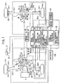
- the brake actuator 40 a hydraulic unit comprising a pressurizing device, a reducing valve and intensifier, can apply brake pressure to the wheel cylinders 43fl, 43fr, 43rl and 43rr respectively, independently and controllably corresponding to input signals.
- the power distribution controller 60 controls the transfer clutch 21.
- Application of differential limiting force to the center differential 3 is basically controlled referring to a table map of predetermined duty ratios determined by variables of throttle opening ⁇ th and vehicle speed V in different control modes, i.e., a normal control mode, a starting control mode, a steering control mode, a slip control mode or the like.
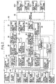
- the left/right wheel limiter controller 70 receives control signals from the vehicle movement control alterant 100 so that the control of the hydraulic multi-plate clutch 33 is carried out by instructions from the vehicle movement control alterant 100.
- the aimed yaw rate differential operator 87 calculates an aimed yaw rate differential S ⁇ ' which is a differential value of the aimed yaw rate ⁇ ' determined by the aimed yaw rate calculator 84 and the predicted yaw rate differential operator 88 calculates a predicted yaw rate differential S ⁇ ' LOW which is a differential value of the predicted yaw rate ⁇ ' LOW determined by the predicted yaw rate calculator 86.
- the braking wheel discriminator 94 selects which wheel is to be applied with braking from combinations of signs of the real yaw rate ⁇ and the yaw rate deflection ⁇ .
- the following combinations are provided. Signs of the real yaw rate ⁇ and the aimed yaw rate ⁇ ' are given in the condition, i.e. (+)plus in a direction of left turning and (-)minus in a direction of right turning.
- ⁇ a small and plus figure close to 0, predetermined by experiments or calculation is employed.
- ⁇ a small and plus figure close to 0, predetermined by experiments or calculation is employed.
- the output judgement 95 receives signals from the vehicle movement control alterant 100. Threshold is set smaller in the output judgement 95 according to an instruction from the vehicle movement control alterant 100 so that control sensitivity is changeable towards a direction where braking control is carried out promptly.
- the vehicle is equipped with a navigator 110, which is a running position locating means for determining location of the running vehicle, a road geometry detector 130 and a curve geometry calculator 120, which are curve data creating means for acquiring curve data while detecting vehicle position and a curve in front of the vehicle.
- a navigator 110 which is a running position locating means for determining location of the running vehicle
- a road geometry detector 130 and a curve geometry calculator 120, which are curve data creating means for acquiring curve data while detecting vehicle position and a curve in front of the vehicle.
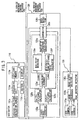
- the auxiliary memory 110b is a CD-ROM device, containing a CD-ROM in which road information is stored, topographical information and other road map information.
- road map information is stored at several hierarchical levels in varying scales as well as road type information such as motor ways, ordinary national roads and local roads, and information on passage conditions of intersections.
- the road data included in the road map information consist of point data (nodes) entered at given intervals of space and line data(link) formed by connecting these nodes.
- a pair of stereoimages taken by the CCD cameras 130a are fed to the image processor 130b that determines distance data over the entire image field by way of trigonometric calculations according to the deflections of the positions of objects in respective each images, so as to generate a 3D-image showing distances.
- the generated 3D-image is sent to the road width detector 130c.
- the curve geometry calculator 120 comprises a three-node detector 120a, a Pn-1 Pn distance calculator 120b, a Pn Pn+1 distance calculator 120c, a long/short judgment section 120d, a mid-point calculator 120e, a mid-point-same-distance point calculator 120f, a radius calculator 120g and a corrector 120h.
- Pn-1, Pn, and Pn+1 are represented by (Xn-1,Yn-1), (Xn, Yn), and (Xn+1, Yn+1), respectively.
- the representative node of the curve is Pn. Therefore, the curve data at points P1, P2, ..., and Pn are calculated by the combination of (P0, P1, P2) (P1, P2, P3), ..., and(Pn-1, Pn, Pn+1), respectively.
- the Pn- Pn distance Calculator 120b Calculates a straight distance connecting Pn-1 and Pn based on the positional information of Pn-1 and Pn input from the three-node detector 120a, so as to send the straight distance to the long/short judgment 120d and the corrector section 120h.
- the long/short judgment 120d compares the straight distance connecting Pn-1 and Pn inputted from the Pn-1 Pn distance calculator 120b. and the straight distance connecting Pn and Pn+1 inputted from the Pn Pn+1 distance calculator 120c, so as to judge which is shorter. Every data (position, distance) for the shorter straight distance is outputted to the mid-point calculator 120e and the corrector 120h, while every data (position, distance) for the longer straight distance is outputted to the mid-point-same-distance point calculator 120f.
- the mid-point calculator 120e Based on the every data (position, distance) for the shorter straight line inputted from the long/short judgment 120d, the mid-point calculator 120e not only calculates half of the shorter straight distance, but also determines the mid point position on the shorter straight line.
- the shorter straight line is the straight line connecting Pn-1 and Pn
- the mid-node Pn-1,n is represented as (Xn-1,n , Yn-1,n)
- every data calculated by the mid-point calculator 120e is outputted to the mid-point-same-distance point calculator 120f and the radius calculator 120g.
- the radius calculator 120g determines as the central position "On" of the emerging curve on the road the position of the crossing point of a line that crosses the shorter straight line (here, Pn-1 Pn) at right angle with each other at the mid-node Pn-1,n and a line that crosses the longer straight line (here,PnPn+1) at right angle with each other at the mid-point-same-distance node Pn,n+1.
- interval of nodes is short means that the road is accurately defined by nodes on the map, in that case, corrections of the difference De1n is not significant.
- FIG.4 shows a detailed correction to be made by the corrector 120h.
- the vector from Pn-1 to Pn is denoted as B1ve (ve meaning a vector), and the vector from P2 to P3 is denoted as B2ve.
- the error(ratio) Pdeln between Lon and Rn is as follows:
- the calculated radius of curvature always becomes smaller than the actual radius of curvature, thereby preferable when setting off a proper warning in the warning/detection control when approaching a curve.
- Provision of the corrector 120h for the radius of curvature can help an accurate calculation of the radius of curvature.
- the error set value which a variable in accordance with the actual road geometry and the number of nodes can make calculations more accurate.
- the wider road actually represents the larger radius of curvature, the wider the road width, the larger the error set value, thus eliminating the need or chance for correction.
- a shorter straight line distance results in fine setting of nodes, thus probably representing the road more accurately, so that the shorter the shorter line distance, the larger the error set value, thereby the more eliminating the chance for correction.
- the data reduction 120i is provided to reduce data corrected by the corrector 120h for every node, eliminating unnecessary calculations.
- Deceleration distance R n ⁇ 1 ⁇ R n
- Such data deduced by the data deduction 120i are entered to the vehicle movement control alterant 100 together with data before the deduction.
- the power distribution controller 60 receives respective wheel speed signals from the front left wheel speed sensor 44f1, the front right wheel speed sensor 44fr, the rear left wheel speed sensor 44rl and the rear right wheel seed sensor 44rr, a signal of throttle opening ⁇ th from the throttle opening sensor 45 and a signal of gear position from the gear position sensor 46, and then carry out control of differential limiting force to be applied to the center differential 3, i.e., controlling the transfer torque of the transfer clutch 21 in the normal control mode, the starting control mode, the steering control mode and the slip control mode, referring to the tabulated duty ratio map by throttle opening ⁇ th and vehicle speed V based on running conditions.
- specified torque distribution is front 35/rear 65
- torque distribution varies according to the control form front 35/rear 65 to front 50/rear 50 which is torque distribution at direct coupling of the transfer clutch 21.
- the left/right wheel differential limiter controller 70 receives respective wheel speed signals from the front left wheel speed sensor 44fl, the front right wheel speed sensor 44fr, the rear left wheel speed sensor 44rl and the rear right wheel seed sensor 44rr, a signal of throttle opening ⁇ th from the throttle opening sensor 45, a signal of gear position from the gear position sensor 46, a signal of steering wheel angle ⁇ f from the steering wheel sensor 47 and a signal of longitudinal acceleration Gx from the longitudinal acceleration sensor 50 and then carry out control of limiting differential of the rear left and right wheels by controlling the hydraulic multi-plate clutch 33 of the rear differential 7 according to running conditions.
- the hydraulic pressure set for non-slip conditions is controlled based on the vehicle speed V, e.g., an average of 4 wheel speeds, and the throttle opening ⁇ th by referring to a data map predetermined by experiments and theoretical calculations and characterized in having bigger values as the vehicle speed and load become higher, and is further controlled in corrective way by the longitudinal acceleration and information that the gear position is lower than specified.
- the navigator 100 combines vehicle running data and map data while operating map matching and sends its results to the display 110c based on an operating signal for displaying the current position of the vehicle, the map showing the area, the optimum route to the destination and so on, and also sends its results to the vehicle movement control alterant 100 and the curve geometry calculator 120 as necessary.
- the curve geometry calculator 120 detects three nodes, i.e., the first node, second node and the third node, in the traveling direction from the vehicle on and judges short/ long , on the two straight lines, one staring from the first node and ending at the second node, the other from the second node to the third node.
- a mid point is set on the short line by calculating the half distance of the short line and a mid-point-same-distance point is set on the long line in the half distance of the short line from the second node.
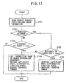
- S104 is taken, where the following signals are sent to the related controllers respectively; a signal setting the insensitive band narrower to the brake controller 80, a signal setting differential limiting force lower (i.e., weakening pressure to be applied to the hydraulic multi-plate clutch 33 of the rear differential 7) to the left/right wheel differential limiter controller 70 and a signal reducing transfer torque (i.e., resuming torque distribution by the center differential to the specified) to the power distribution controller 60. Then the program goes to an end.
- a signal setting the insensitive band narrower to the brake controller 80 a signal setting differential limiting force lower (i.e., weakening pressure to be applied to the hydraulic multi-plate clutch 33 of the rear differential 7) to the left/right wheel differential limiter controller 70 and a signal reducing transfer torque (i.e., resuming torque distribution by the center differential to the specified) to the power distribution controller 60.
- S105 is taken, where it is judged if the distance to the curve end is less than Lcv2, which is predeterminedly given according to variables of, for example, road width, vehicle speed and radius of curvature of curve to be traveled.
- S104 is taken, where the following signals are sent to the related controllers respectively; a signal setting the insensitive band narrower to the brake controller 80, a signal setting differential limiting force smaller (i.e., weakening pressure to be applied to the hydraulic multi-plate clutch 33 of the rear differential 7) to the left/right wheel differential limiter controller 70 and a signal reducing transfer torque (i.e., resuming torque distribution by the center differential to the specified) to the power distribution controller 60. Then the program goes to an end
- S106 is taken, where the following signals are sent to the related controllers respectively; a signal setting differential limiting force bigger (i.e. strengthening pressure to be applied to the hydraulic multi-plate clutch 33 of the rear differential 7) to the left/right differential limiter controller 70 and a signal increasing transfer torque (i.e., torque distribution by the center differential becoming equal for front and rear) to the power distribution controller 60.
- a signal setting differential limiting force bigger i.e. strengthening pressure to be applied to the hydraulic multi-plate clutch 33 of the rear differential
- a signal increasing transfer torque i.e., torque distribution by the center differential becoming equal for front and rear
- left/right wheel differential limiter controller is done on the vehicle which equips it for rear wheels, it is applicable to a vehicle which equips the controller for front wheels.
- the embodiment shows the case where, the characteristic of the brake controller is changed by setting the insensitive band, i.e., threshold of yaw rate deflection, narrower, the similar effect can be obtained, for example as shown in FIG. 5, by narrowly setting an insensitive band of side slip angle, in the case yaw rate deflection is corrected according to side slip.
- the insensitive band i.e., threshold of yaw rate deflection, narrower
- Controlling of the braking force by the brake controller may be other types than shown in the embodiment.
- the vehicle dynamic control system alters characteristics of respective vehicle movement controllers, recognizing beforehand details of a curved road to be traveled, so that the controllers of the system can function properly for coming and foreseeable running conditions and current running conditions and driving through a curve can be done appropriately, including entering in and going out the curve.
Landscapes
- Engineering & Computer Science (AREA)
- Transportation (AREA)
- Mechanical Engineering (AREA)
- Regulating Braking Force (AREA)
- Arrangement And Driving Of Transmission Devices (AREA)
- Arrangement And Mounting Of Devices That Control Transmission Of Motive Force (AREA)
- Hydraulic Control Valves For Brake Systems (AREA)
- Control Of Driving Devices And Active Controlling Of Vehicle (AREA)
- Steering Control In Accordance With Driving Conditions (AREA)
- Traffic Control Systems (AREA)
Claims (6)
- Dynamiksteuerungssystem für ein Fahrzeug mit einem am Fahrzeug montierten Seitenbeschleunigungssensor (49) zum Erfassen einer Beschleunigung des Fahrzeugs in Seitenrichtung und zum Erzeugen eines Seitenbeschleunigungssignals und einer Navigationsvorrichtung (110) mit einer am Fahrzeug montierten GPS-Einrichtung zum Erzeugen einer Fahrzeugpositionsinformation durch Empfangen von Funkwellensignalen von einem Weltraumsatelliten und zum Ausgeben eines Positionssignals;
gekennzeichnet durch:eine auf das Positionssignal ansprechende Kurveninformationsberechnungseinrichtung (120) zum Abrufen von Information über eine Kurve, die das Fahrzeug durchfahren wird, unter Bezug auf in einer Speichereinrichtung (130) gespeicherte Daten und zum Ausgeben eines Informationssignals;eine Fahrzeugdynamiksteuerungseinrichtung (60, 70, 80), die auf das Informationssignal und das Seitenbeschleunigungssignal anspricht und dazu geeignet ist, eine dynamische Bewegung des Fahrzeugs auf einen optimalen Fahrzustand entsprechend einer Fahrposition zu steuern und ein Dynamiksteuerungssignal zu erzeugen; undeine auf das Positionssignal und das Informationssignal ansprechende Fahrzeugbewegungsänderungseinrichtung (100) zum Ändern der dynamischen Bewegung innerhalb eines vorgegebenen Abstands vor dem Eintritt in die Kurve, um eine Lenkfähigkeit durch Erhöhen einer Empfindlichkeit der Fahrzeugdynamiksteuerungseinrichtung (60, 70, 80) und eine Fahrzeugstabilität durch Ändern eines Übertragungsdrehmoments der Fahrzeugdynamiksteuerungseinrichtung während einer Fahrt durch die Kurve zu verbessern. - Fahrzeugsteuerungssystem nach Anspruch 1, wobei die Fahrzeugbewegungsänderungseinrichtung eine Charakteristik der Fahrzeugdynamiksteuerungseinrichtung in eine Charakteristik ändert, die für eine Lagestabilisierung des Fahrzeugs vorteilhaft ist, während das Fahrzeug eine Kurve durchfährt und sich innerhalb eines vorgegebenen Abstands vom Kurvenende befindet, und in eine andere Charakteristik, die für eine Kurvenfahrt vorteilhaft ist, wenn das Fahrzeug eine Kurve durchfährt und sich außerhalb eines vorgegebenen Abstands vom Kurvenende befindet.
- Fahrzeugsteuerungssystem nach Anspruch 1, wobei die Fahrzeugdynamiksteuerungseinrichtung mindestens eine der folgenden Einrichtungen ist: eine Bremsensteuerung zum Ausüben einer Bremskraft auf ein Rad, das basierend auf Fahrzeugfahrzuständen auf eine vorgegebene Weise ausgewählt wird, eine Differentialbegrenzungssteuerung für ein linkes/rechtes Rad zum Steuern der Differentialbegrenzungskraft zwischen linken und rechten Rädern und eine Kraftverteilungssteuerung zum Steuern der Differentialbegrenzungskraft, die auf ein Mitteldifferential zwischen den Vorder- und den Hinterrädern zum Verteilen der Antriebskraft auf Vorder- und Hinterräder ausgeübt wird, basierend auf den Fahrzeugfahrzuständen.
- Fahrzeugsteuerungssystem nach Anspruch 3, wobei die Änderung einer Charakteristik der Fahrzeugdynamiksteuerungseinrichtung in eine für eine Kurvenfahrt vorteilhafte Charakteristik durch Ändern von Steuerparametern implementiert wird, wobei die Fahrzeugdynamiksteuerungseinrichtung die Bremsensteuerung ist.
- Fahrzeugsteuerungssystem nach Anspruch 3, wobei die Änderung einer Charakteristik der Fahrzeugdynamiksteuerungseinrichtung in eine für eine Kurvenfahrt vorteilhafte Charakteristik durch Reduzieren der Differentialbegrenzungskraft zwischen den linken und rechten Rädern implementiert wird, und wobei die Änderung in eine für eine Fahrtstabilisierung vorteilhafte andere Charakteristik durch Erhöhen der Differentialbegrenzungskraft zwischen den linken und rechten Rädern implementiert wird, wobei die Fahrzeugdynamiksteuerungseinrichtung die Differentialbegrenzungssteuerungseinrichtung für das linke/rechte Rad ist.
- Fahrzeugsteuerungssystem nach Anspruch 3, wobei die Änderung einer Charakteristik der Fahrzeugdynamiksteuerungseinrichtung in eine für eine Kurvenfahrt vorteilhafte Charakteristik implementiert wird, indem die Differentialbegrenzungskraft derart gesetzt wird, dass eine ungleichmäßige Drehmomentverteilung zwischen den Vorder- und den Hinterrädern erhalten wird, und wobei die Änderung in eine für eine Fahrtstabilisierung vorteilhafte andere Charakteristik implementiert wird, indem die Differentialbegrenzungskraft derart gesetzt wird, dass eine gleichmäßige Drehmomentverteilung zwischen den Vorder- und den Hinterrädern erhalten wird, wobei die Fahrzeugdynamiksteuerungseinrichtung die Kraftverteilungssteuerung zum Steuern der auf ein Mitteldifferential ausgeübten Differentialbegrenzungskraft ist.
Applications Claiming Priority (3)
| Application Number | Priority Date | Filing Date | Title |
|---|---|---|---|
| JP28878597 | 1997-10-21 | ||
| JP28878597A JP3850530B2 (ja) | 1997-10-21 | 1997-10-21 | 車両運動制御装置 |
| JP288785/97 | 1997-10-21 |
Publications (3)
| Publication Number | Publication Date |
|---|---|
| EP0911234A2 EP0911234A2 (de) | 1999-04-28 |
| EP0911234A3 EP0911234A3 (de) | 2000-01-26 |
| EP0911234B1 true EP0911234B1 (de) | 2006-04-12 |
Family
ID=17734699
Family Applications (1)
| Application Number | Title | Priority Date | Filing Date |
|---|---|---|---|
| EP98308597A Expired - Lifetime EP0911234B1 (de) | 1997-10-21 | 1998-10-21 | Kraftfahrzeugdynamik- Steuersystem |
Country Status (4)
| Country | Link |
|---|---|
| US (1) | US6219609B1 (de) |
| EP (1) | EP0911234B1 (de) |
| JP (1) | JP3850530B2 (de) |
| DE (1) | DE69834162T2 (de) |
Cited By (1)
| Publication number | Priority date | Publication date | Assignee | Title |
|---|---|---|---|---|
| TWI876590B (zh) * | 2023-10-16 | 2025-03-11 | 鴻華先進科技股份有限公司 | 行動載具之驅動系統的控制方法以及控制系統 |
Families Citing this family (71)
| Publication number | Priority date | Publication date | Assignee | Title |
|---|---|---|---|---|
| JP3015875B2 (ja) * | 1998-05-19 | 2000-03-06 | 工業技術院長 | 自動車運転時の車線逸脱検出方法及び検出装置 |
| DE19913825A1 (de) * | 1999-03-26 | 2000-09-28 | Bosch Gmbh Robert | Regelsystem für ein Fahrzeug |
| DE19920065C2 (de) * | 1999-05-03 | 2003-04-10 | Daimler Chrysler Ag | Verfahren zur Durchführung einer automatisierten Kupplungsbetätigung |
| JP2000344077A (ja) * | 1999-06-08 | 2000-12-12 | Toyota Motor Corp | 車両の挙動制御装置 |
| JP2003509665A (ja) * | 1999-09-15 | 2003-03-11 | コンティネンタル・テーベス・アクチエンゲゼルシヤフト・ウント・コンパニー・オッフェネ・ハンデルスゲゼルシヤフト | 自動車の走行動特性状態を検出および評価する方法 |
| DE19954131B4 (de) * | 1999-11-11 | 2008-12-24 | Zf Friedrichshafen Ag | Verfahren zum Reduzieren eines Radschlupfs eines Kraftfahrzeugs |
| JP3696466B2 (ja) * | 2000-01-31 | 2005-09-21 | 光洋精工株式会社 | 車両用操舵装置 |
| GB0002292D0 (en) | 2000-02-02 | 2000-03-22 | Jaguar Cars | Motor vehicle dynamic stability control |
| GB2358975B (en) * | 2000-02-05 | 2004-05-05 | Jaguar Cars | Motor vehicle trajectory measurement |
| US6415215B1 (en) * | 2000-02-23 | 2002-07-02 | Koyo Seiko Co., Ltd. | Vehicle attitude control apparatus |
| JP3978569B2 (ja) * | 2000-10-06 | 2007-09-19 | 三菱自動車工業株式会社 | 車両用駆動力配分装置 |
| JP4187918B2 (ja) * | 2000-10-11 | 2008-11-26 | 富士重工業株式会社 | 車両挙動制御装置 |
| GB0114424D0 (en) * | 2001-06-13 | 2001-08-08 | Ricardo Consulting Eng | Improved vehicle control |
| JP4590789B2 (ja) * | 2001-07-02 | 2010-12-01 | マツダ株式会社 | 自動車の姿勢制御装置 |
| US20030022681A1 (en) * | 2001-07-24 | 2003-01-30 | Ruppel Christopher D. | Adaptive dynamic technique for multi-path signal processing |
| US6675074B2 (en) * | 2001-08-21 | 2004-01-06 | Robert Bosch Gmbh | Method and system for vehicle trajectory estimation |
| JP3760827B2 (ja) | 2001-09-28 | 2006-03-29 | 日産自動車株式会社 | 車線逸脱防止装置 |
| JP3871550B2 (ja) * | 2001-10-31 | 2007-01-24 | 株式会社ジェイテクト | 4輪駆動車の駆動力配分制御装置 |
| JP2003184599A (ja) * | 2001-12-12 | 2003-07-03 | Aisin Seiki Co Ltd | 車輌の挙動制御装置 |
| DE60304388T2 (de) * | 2002-05-22 | 2007-06-06 | Nissan Motor Co., Ltd., Yokohama | Fahrdynamik-Regelsystem für ein vierradgetriebenes Fahrzeug |
| US7283897B2 (en) * | 2002-05-31 | 2007-10-16 | Quantum Engineering, Inc. | Method and system for compensating for wheel wear on a train |
| US7272482B2 (en) * | 2002-09-30 | 2007-09-18 | Nissan Motor Co., Ltd. | Preceding-vehicle following control system |
| JP3940056B2 (ja) * | 2002-10-11 | 2007-07-04 | アイシン精機株式会社 | 路面状態推定装置、及び該装置を備えた車両の運動制御装置 |
| GB2394702A (en) * | 2002-10-30 | 2004-05-05 | Trw Ltd | Video enhanced stability control in road vehicles |
| JP4148125B2 (ja) * | 2003-12-09 | 2008-09-10 | 日産自動車株式会社 | 減速制御装置 |
| JP2005271822A (ja) * | 2004-03-25 | 2005-10-06 | Mitsubishi Fuso Truck & Bus Corp | 車両の自動減速制御装置 |
| JP4269994B2 (ja) * | 2004-03-25 | 2009-05-27 | 三菱ふそうトラック・バス株式会社 | 車両のステア特性制御装置 |
| US8657389B2 (en) * | 2004-05-20 | 2014-02-25 | Honda Motor Co., Ltd. | Cooperative traction control system |
| JP4500126B2 (ja) * | 2004-08-02 | 2010-07-14 | 富士重工業株式会社 | ヨーレートセンサの故障診断装置 |
| JP4638185B2 (ja) * | 2004-08-04 | 2011-02-23 | 富士重工業株式会社 | 車両の挙動制御装置 |
| JP2006112463A (ja) * | 2004-10-12 | 2006-04-27 | Gkn ドライブライン トルクテクノロジー株式会社 | デファレンシャル装置の差動ロック制御装置及び差動ロック制御方法 |
| US7276014B2 (en) * | 2004-11-05 | 2007-10-02 | Ntn Corporation | Vehicle stability control system for enhanced transfer case compatibility |
| JP4704767B2 (ja) * | 2004-12-10 | 2011-06-22 | Gknドライブラインジャパン株式会社 | 車両駆動制御装置 |
| JP4640696B2 (ja) * | 2005-03-03 | 2011-03-02 | 株式会社ジェイテクト | 車両姿勢制御システム |
| JP4696224B2 (ja) * | 2005-07-19 | 2011-06-08 | 三菱自動車工業株式会社 | 4輪駆動車の差動制限制御装置 |
| JP4852931B2 (ja) * | 2005-08-23 | 2012-01-11 | 日産自動車株式会社 | 車両の左右トルク配分制御装置 |
| JP2007099126A (ja) * | 2005-10-05 | 2007-04-19 | Denso Corp | 車両制御装置 |
| US7337053B2 (en) * | 2006-02-15 | 2008-02-26 | Eaton Corporation | Stability-enhanced traction control with electrically controlled center coupler |
| US20070282558A1 (en) * | 2006-06-01 | 2007-12-06 | Denso Corporation | Abnormal condition determining system for steering angle sensor |
| JP4826349B2 (ja) * | 2006-06-09 | 2011-11-30 | トヨタ自動車株式会社 | 車両用車線維持支援装置 |
| JP4636012B2 (ja) * | 2006-12-11 | 2011-02-23 | トヨタ自動車株式会社 | 車両の制動制御装置 |
| US7865285B2 (en) * | 2006-12-27 | 2011-01-04 | Caterpillar Inc | Machine control system and method |
| US8248984B2 (en) * | 2007-06-20 | 2012-08-21 | I Squared Llc | System and method for interfacing devices |
| JP4980168B2 (ja) * | 2007-08-01 | 2012-07-18 | 富士重工業株式会社 | 車両挙動制御装置 |
| JP5029342B2 (ja) * | 2007-12-17 | 2012-09-19 | トヨタ自動車株式会社 | 車両運動制御システム |
| US8131424B2 (en) * | 2008-01-16 | 2012-03-06 | GM Global Technology Operations LLC | Methods and systems for calculating yaw gain for use in controlling a vehicle |
| DE102008035098A1 (de) * | 2008-07-28 | 2010-02-04 | GM Global Technology Operations, Inc., Detroit | Verfahren zum Betreiben eines Kraftfahrzeugs und Kraftfahrzeug |
| JP5137764B2 (ja) * | 2008-09-29 | 2013-02-06 | 株式会社アドヴィックス | 車両の速度制御装置 |
| JP4842335B2 (ja) * | 2009-02-12 | 2011-12-21 | 日立建機株式会社 | 電動車両の旋回補助装置 |
| US8890747B2 (en) * | 2009-02-25 | 2014-11-18 | GM Global Technology Operations LLC | Longitudinal and lateral velocity estimation using single antenna GPS and magnetic compass |
| JP4873042B2 (ja) * | 2009-04-13 | 2012-02-08 | トヨタ自動車株式会社 | 車両制御装置および車両制御方法 |
| US8306686B2 (en) * | 2009-04-23 | 2012-11-06 | GM Global Technology Operations LLC | GPS based vehicle modification and abnormal usage monitoring |
| US9096201B2 (en) * | 2011-03-18 | 2015-08-04 | Robert Bosch Gmbh | Yaw rate forecasting |
| SE538840C2 (sv) * | 2011-11-28 | 2016-12-27 | Scania Cv Ab | Säkerhetssystem för ett fordon |
| US8855869B2 (en) * | 2011-12-12 | 2014-10-07 | Caterpillar Inc. | Determining a ground speed of a machine |
| EP2855217B1 (de) | 2012-06-21 | 2019-05-01 | Eaton Corporation | Prädiktives fahrzeugstabilitätsregelungsverfahren |
| JP5658717B2 (ja) | 2012-08-09 | 2015-01-28 | 富士重工業株式会社 | 4輪駆動車の制御装置 |
| JP5483770B2 (ja) * | 2012-09-21 | 2014-05-07 | 富士重工業株式会社 | 4輪駆動車の制御装置 |
| DE102012020906A1 (de) * | 2012-10-24 | 2014-04-24 | Audi Ag | Verfahren und System zum Betreiben eines Antriebsstrangs eines Kraftwagens |
| US20140324290A1 (en) * | 2013-04-30 | 2014-10-30 | Ford Global Technologies, Llc | Traction and Cornering Properties of a Motor Vehicle |
| JP5856133B2 (ja) * | 2013-12-11 | 2016-02-09 | 本田技研工業株式会社 | 車両用制動システム |
| DE102015010173B3 (de) * | 2015-08-06 | 2016-07-14 | Audi Ag | Verfahren zur Schwimmwinkelmessung in Fahrzeugen |
| US9884632B2 (en) * | 2015-08-12 | 2018-02-06 | Inrix Inc. | Personal vehicle management |
| GB2545463B (en) * | 2015-12-17 | 2019-07-17 | Jaguar Land Rover Ltd | Method for controlling a vehicle |
| JP6432572B2 (ja) * | 2016-08-22 | 2018-12-05 | トヨタ自動車株式会社 | 表示装置、表示システム |
| JP6765908B2 (ja) * | 2016-09-07 | 2020-10-07 | Ntn株式会社 | 車両の旋回制御装置 |
| JP6868173B2 (ja) * | 2016-09-20 | 2021-05-12 | 日立Astemo株式会社 | 車両制御装置、車両制御方法および電動パワーステアリング装置 |
| DE102017203362A1 (de) * | 2017-03-01 | 2018-09-06 | Audi Ag | Einstellen einer Drehmomentverteilung zwischen Rädern einer Achse eines Kraftfahrzeugs durch Betätigen einer Bedieneinheit |
| JP6986463B2 (ja) * | 2018-02-13 | 2021-12-22 | 日立Astemo株式会社 | 運転支援装置、運転支援方法及び運転支援システム |
| DE102019207305A1 (de) * | 2019-05-20 | 2020-11-26 | Zf Friedrichshafen Ag | Verfahren zur Regelung je einer Sperreinrichtung mindestens eines Differentialgetriebes |
| US20260028001A1 (en) * | 2024-07-25 | 2026-01-29 | GM Global Technology Operations LLC | Automated and manual brake torque biasing |
Family Cites Families (27)
| Publication number | Priority date | Publication date | Assignee | Title |
|---|---|---|---|---|
| US4898431A (en) | 1988-06-15 | 1990-02-06 | Aisin Seiki Kabushiki Kaisha | Brake controlling system |
| US5265020A (en) * | 1990-04-20 | 1993-11-23 | Mazda Motor Corporation | Torque distribution control apparatus for four wheel drive |
| JP2623905B2 (ja) * | 1990-04-20 | 1997-06-25 | 日産自動車株式会社 | 車両用駆動系クラッチ制御装置 |
| JP3133770B2 (ja) | 1991-01-18 | 2001-02-13 | マツダ株式会社 | 自動車の走行システム |
| US5301768A (en) * | 1992-05-04 | 1994-04-12 | Aisin Aw Co., Ltd. | Four-wheel drive torque transfer mechanism |
| JPH06115370A (ja) * | 1992-10-05 | 1994-04-26 | Mazda Motor Corp | 車両の従動輪差動制限装置 |
| JP3433812B2 (ja) * | 1992-10-05 | 2003-08-04 | マツダ株式会社 | 車両の従動輪差動制限装置 |
| JPH06115372A (ja) * | 1992-10-05 | 1994-04-26 | Mazda Motor Corp | 車両の従動輪差動制限装置 |
| JPH06115371A (ja) * | 1992-10-05 | 1994-04-26 | Mazda Motor Corp | 車両の従動輪差動制限装置 |
| DE4333961A1 (de) * | 1992-10-05 | 1994-04-07 | Mazda Motor | Vorrichtung zur Begrenzung des Antriebsrad-Differentials für Fahrzeuge |
| JPH06247169A (ja) * | 1993-02-22 | 1994-09-06 | Mazda Motor Corp | 車両の駆動装置 |
| JP3327970B2 (ja) * | 1993-02-22 | 2002-09-24 | マツダ株式会社 | 車両の駆動装置 |
| JP3201094B2 (ja) * | 1993-09-16 | 2001-08-20 | 三菱自動車工業株式会社 | 車両用自動操舵装置 |
| JP3246119B2 (ja) * | 1993-09-16 | 2002-01-15 | 三菱自動車工業株式会社 | 車両用自動操舵装置 |
| JP3366096B2 (ja) * | 1994-02-16 | 2003-01-14 | 本田技研工業株式会社 | 車両の走行制御装置 |
| US5661650A (en) * | 1994-02-23 | 1997-08-26 | Honda Giken Kogyo Kabushiki Kaisha | System for controlling a vehicle relative to a judged shape of a travel road |
| JP3432881B2 (ja) * | 1994-02-23 | 2003-08-04 | 本田技研工業株式会社 | 車両制御装置 |
| JPH07334789A (ja) * | 1994-06-13 | 1995-12-22 | Oki Electric Ind Co Ltd | マイクロチップを内蔵した道路標識、ならびにこれを用いた路車間通信システム |
| JP3269927B2 (ja) * | 1994-11-30 | 2002-04-02 | 本田技研工業株式会社 | 車両の操舵制御装置 |
| JPH08205306A (ja) * | 1995-01-27 | 1996-08-09 | Fuji Heavy Ind Ltd | 車両の警報装置 |
| JP3577372B2 (ja) | 1995-09-11 | 2004-10-13 | 富士重工業株式会社 | 制動力制御装置 |
| DE19604364A1 (de) * | 1996-02-07 | 1997-08-14 | Fraunhofer Ges Forschung | Verfahren zur Ermittlung einer Straßenkrümmung aus digital abgelegten Karteninformationen |
| JP3223239B2 (ja) * | 1996-11-12 | 2001-10-29 | 本田技研工業株式会社 | 車両制御装置 |
| JP3388132B2 (ja) * | 1997-04-09 | 2003-03-17 | 本田技研工業株式会社 | 車両制御装置 |
| JP3882304B2 (ja) * | 1997-07-04 | 2007-02-14 | 日産自動車株式会社 | 自動走行用自車位置検出装置 |
| JP3521691B2 (ja) * | 1997-07-07 | 2004-04-19 | 日産自動車株式会社 | 車両走行制御装置 |
| JP3366225B2 (ja) * | 1997-07-09 | 2003-01-14 | 本田技研工業株式会社 | ナビゲーション装置及び車両制御装置 |
-
1997
- 1997-10-21 JP JP28878597A patent/JP3850530B2/ja not_active Expired - Lifetime
-
1998
- 1998-10-19 US US09/174,538 patent/US6219609B1/en not_active Expired - Lifetime
- 1998-10-21 DE DE69834162T patent/DE69834162T2/de not_active Expired - Lifetime
- 1998-10-21 EP EP98308597A patent/EP0911234B1/de not_active Expired - Lifetime
Cited By (1)
| Publication number | Priority date | Publication date | Assignee | Title |
|---|---|---|---|---|
| TWI876590B (zh) * | 2023-10-16 | 2025-03-11 | 鴻華先進科技股份有限公司 | 行動載具之驅動系統的控制方法以及控制系統 |
Also Published As
| Publication number | Publication date |
|---|---|
| DE69834162T2 (de) | 2007-03-08 |
| DE69834162D1 (de) | 2006-05-24 |
| EP0911234A3 (de) | 2000-01-26 |
| JPH11115554A (ja) | 1999-04-27 |
| JP3850530B2 (ja) | 2006-11-29 |
| EP0911234A2 (de) | 1999-04-28 |
| US6219609B1 (en) | 2001-04-17 |
Similar Documents
| Publication | Publication Date | Title |
|---|---|---|
| EP0911234B1 (de) | Kraftfahrzeugdynamik- Steuersystem | |
| US9145165B2 (en) | Drive controlling apparatus for a vehicle | |
| US6584399B2 (en) | Traction control system of vehicles combining feedback control with feedforward control | |
| EP1514754B1 (de) | Fahrzeugschlupfwinkelschätzverfahren und -system | |
| US6178368B1 (en) | Roll control device of vehicles with tracing of turning course | |
| US7058494B2 (en) | Vehicle dynamics control apparatus | |
| US6704622B2 (en) | Vehicle stability control | |
| US6208927B1 (en) | Vehicle maneuvering control device | |
| US6188316B1 (en) | Vehicle dynamic control system | |
| US7319927B1 (en) | Constant speed control system | |
| EP1129917B1 (de) | Bewegungssteuerungssystem für ein Kraftfahrzeug | |
| EP2626264B1 (de) | Bewegungssteuersystem für ein Fahrzeug basierend auf Ruckinformation | |
| US6473682B2 (en) | Apparatus and method for estimating maximum road friction coefficient | |
| JP3334647B2 (ja) | 車両のヨーレイト検出装置 | |
| US6697728B2 (en) | Vehicle motion control system | |
| JP2002120711A (ja) | 車両挙動制御装置 | |
| JPS61229620A (ja) | 自動車の伝動要素を自動的に投入およびしや断する装置 | |
| US12371034B2 (en) | Redundant control system and method for autonomous steering | |
| CN103057546A (zh) | 车辆控制设备以及车辆控制方法 | |
| US7873459B2 (en) | Load transfer adaptive traction control system | |
| JP4094103B2 (ja) | 車両運動制御装置 | |
| JPH11151956A (ja) | 車両運動制御装置 | |
| US12319289B2 (en) | Driver assistance apparatus | |
| US20250304061A1 (en) | Speed control system for a vehicle and method | |
| JPH0948254A (ja) | 四輪駆動車のトルク配分装置 |
Legal Events
| Date | Code | Title | Description |
|---|---|---|---|
| PUAI | Public reference made under article 153(3) epc to a published international application that has entered the european phase |
Free format text: ORIGINAL CODE: 0009012 |
|
| AK | Designated contracting states |
Kind code of ref document: A2 Designated state(s): DE GB |
|
| AX | Request for extension of the european patent |
Free format text: AL;LT;LV;MK;RO;SI |
|
| PUAL | Search report despatched |
Free format text: ORIGINAL CODE: 0009013 |
|
| AK | Designated contracting states |
Kind code of ref document: A3 Designated state(s): AT BE CH CY DE DK ES FI FR GB GR IE IT LI LU MC NL PT SE |
|
| AX | Request for extension of the european patent |
Free format text: AL;LT;LV;MK;RO;SI |
|
| 17P | Request for examination filed |
Effective date: 20000717 |
|
| AKX | Designation fees paid |
Free format text: DE GB |
|
| 17Q | First examination report despatched |
Effective date: 20030509 |
|
| GRAP | Despatch of communication of intention to grant a patent |
Free format text: ORIGINAL CODE: EPIDOSNIGR1 |
|
| RTI1 | Title (correction) |
Free format text: DYNAMIC VEHICLE CONTROL SYSTEM |
|
| GRAS | Grant fee paid |
Free format text: ORIGINAL CODE: EPIDOSNIGR3 |
|
| GRAA | (expected) grant |
Free format text: ORIGINAL CODE: 0009210 |
|
| AK | Designated contracting states |
Kind code of ref document: B1 Designated state(s): DE GB |
|
| REG | Reference to a national code |
Ref country code: GB Ref legal event code: FG4D |
|
| REF | Corresponds to: |
Ref document number: 69834162 Country of ref document: DE Date of ref document: 20060524 Kind code of ref document: P |
|
| PLBE | No opposition filed within time limit |
Free format text: ORIGINAL CODE: 0009261 |
|
| STAA | Information on the status of an ep patent application or granted ep patent |
Free format text: STATUS: NO OPPOSITION FILED WITHIN TIME LIMIT |
|
| 26N | No opposition filed |
Effective date: 20070115 |
|
| GBPC | Gb: european patent ceased through non-payment of renewal fee |
Effective date: 20061021 |
|
| PG25 | Lapsed in a contracting state [announced via postgrant information from national office to epo] |
Ref country code: GB Free format text: LAPSE BECAUSE OF NON-PAYMENT OF DUE FEES Effective date: 20061021 |
|
| REG | Reference to a national code |
Ref country code: DE Ref legal event code: R082 Ref document number: 69834162 Country of ref document: DE Representative=s name: VOSSIUS & PARTNER PATENTANWAELTE RECHTSANWAELT, DE Ref country code: DE Ref legal event code: R081 Ref document number: 69834162 Country of ref document: DE Owner name: SUBARU CORPORATION, JP Free format text: FORMER OWNER: FUJI JUKOGYO K.K., TOKIO/TOKYO, JP |
|
| PGFP | Annual fee paid to national office [announced via postgrant information from national office to epo] |
Ref country code: DE Payment date: 20171018 Year of fee payment: 20 |
|
| REG | Reference to a national code |
Ref country code: DE Ref legal event code: R071 Ref document number: 69834162 Country of ref document: DE |