EP0806550B2 - Dispositif de commande du calage des soupapes - Google Patents
Dispositif de commande du calage des soupapes Download PDFInfo
- Publication number
- EP0806550B2 EP0806550B2 EP97302104A EP97302104A EP0806550B2 EP 0806550 B2 EP0806550 B2 EP 0806550B2 EP 97302104 A EP97302104 A EP 97302104A EP 97302104 A EP97302104 A EP 97302104A EP 0806550 B2 EP0806550 B2 EP 0806550B2
- Authority
- EP
- European Patent Office
- Prior art keywords
- rotor
- spring
- valve timing
- coil
- control device
- Prior art date
- Legal status (The legal status is an assumption and is not a legal conclusion. Google has not performed a legal analysis and makes no representation as to the accuracy of the status listed.)
- Expired - Lifetime
Links
Images


Classifications
-
- F—MECHANICAL ENGINEERING; LIGHTING; HEATING; WEAPONS; BLASTING
- F01—MACHINES OR ENGINES IN GENERAL; ENGINE PLANTS IN GENERAL; STEAM ENGINES
- F01L—CYCLICALLY OPERATING VALVES FOR MACHINES OR ENGINES
- F01L1/00—Valve-gear or valve arrangements, e.g. lift-valve gear
- F01L1/34—Valve-gear or valve arrangements, e.g. lift-valve gear characterised by the provision of means for changing the timing of the valves without changing the duration of opening and without affecting the magnitude of the valve lift
- F01L1/344—Valve-gear or valve arrangements, e.g. lift-valve gear characterised by the provision of means for changing the timing of the valves without changing the duration of opening and without affecting the magnitude of the valve lift changing the angular relationship between crankshaft and camshaft, e.g. using helicoidal gear
- F01L1/3442—Valve-gear or valve arrangements, e.g. lift-valve gear characterised by the provision of means for changing the timing of the valves without changing the duration of opening and without affecting the magnitude of the valve lift changing the angular relationship between crankshaft and camshaft, e.g. using helicoidal gear using hydraulic chambers with variable volume to transmit the rotating force
- F01L2001/34423—Details relating to the hydraulic feeding circuit
- F01L2001/34446—Fluid accumulators for the feeding circuit
-
- F—MECHANICAL ENGINEERING; LIGHTING; HEATING; WEAPONS; BLASTING
- F01—MACHINES OR ENGINES IN GENERAL; ENGINE PLANTS IN GENERAL; STEAM ENGINES
- F01L—CYCLICALLY OPERATING VALVES FOR MACHINES OR ENGINES
- F01L1/00—Valve-gear or valve arrangements, e.g. lift-valve gear
- F01L1/34—Valve-gear or valve arrangements, e.g. lift-valve gear characterised by the provision of means for changing the timing of the valves without changing the duration of opening and without affecting the magnitude of the valve lift
- F01L1/344—Valve-gear or valve arrangements, e.g. lift-valve gear characterised by the provision of means for changing the timing of the valves without changing the duration of opening and without affecting the magnitude of the valve lift changing the angular relationship between crankshaft and camshaft, e.g. using helicoidal gear
- F01L1/3442—Valve-gear or valve arrangements, e.g. lift-valve gear characterised by the provision of means for changing the timing of the valves without changing the duration of opening and without affecting the magnitude of the valve lift changing the angular relationship between crankshaft and camshaft, e.g. using helicoidal gear using hydraulic chambers with variable volume to transmit the rotating force
- F01L2001/3445—Details relating to the hydraulic means for changing the angular relationship
- F01L2001/34483—Phaser return springs
Definitions
- the present invention relates to a valve timing control device and in particular to the valve timing control device for controlling an angular phase difference between a crank shaft of a combustion engine and a cam shaft of the combustion engine.
- valve timing of a combustion engine is determined by valve mechanisms driven by cam shafts according to a characteristic of the combustion engine or a specification of the combustion engine. Since a condition of the combustion is changed in response to the rotational speed of the combustion engine, however, it is difficult to obtain optimum valve timing through the whole rotational range. Therefore, a valve timing control device which is able to change valve timing in response to the condition of the combustion engine has been proposed as an auxiliary mechanism of the valve mechanism in recent years.
- a conventional device of this kind is disclosed, for example, in U.S. Patent No. 4,858,572 .
- This device includes a rotor which is fixed on the cam shaft, a drive member which is driven by the rotational torque from a crank shaft and which is rotatably mounted on the cam shaft so as to surround the rotor, a plurality of chambers which are defined between the drive member and the rotor and each of which has a pair of. circumferentially opposed walls and a plurality of vanes which are mounted to the rotor and which extend outwardly therefrom in the radial direction into the chambers so as to divide each of the chambers into a first pressure chamber and a second pressure chamber.
- fluid under pressure is supplied to a selected one of the first pressure chamber and the second pressure chamber in response to the running condition of the combustion engine and an angular phase difference between the crank shaft and the cam shaft is controlled so as to advance or retard the valve timing relative to the crank shaft.
- the fluid under pressure is delivered from an oil pump.
- the valve timing control device is in the maximum advanced condition when each of the vanes contacts with one of the opposed walls of each of the chambers.
- the valve timing control device is in the maximum retarded condition when each of the vanes contacts with the other of the opposed walls of each of the chambers.
- the opening and closing timing of the exhaust valves is delayed because of the above operation of retarding the valve timing. It makes an overlap phenomenon bigger.
- the overlap phenomenon means the exhaust valves and the intake valves are opening at the same time.
- a valve timing control device comprising: a rotor fixed on a cam shaft of an engine, a housing member rotatably mounted on the cam shaft so as to surround the rotor, means for driving the housing member from a rotational output of the engine; a chamber defined between the housing member and the rotor and having a pair of circumferentially opposed walls; a vane mounted on the rotor and extending outwardly therefrom in the radial direction into the chamber so as to divide the chamber into a first pressure chamber and a second pressure chamber; a fluid supplying means for supplying fluid under pressure selectively to one of the first and second pressure chambers thereby establishing a pressure differential between said pressure chambers so as to effect relative rotation between the rotor and the housing member; and means for locking the rotor and the housing member in a predetermined relative angular disposition and for selectively releasing that locking engagement; CHARACTERIZED IN THAT a spring element is provided within the device to urge the rotor towards the
- FIG. 1 to FIG. 7 show a first embodiment of the present invention.
- a valve timing control device of the first embodiment includes an exhaust cam shaft 10, a sensor plate 20, a rotor 30, a plurality of vanes 40 and a housing 50.
- the exhaust cam shaft 10 is rotatably mounted on a cylinder head 80 of an engine E.
- the exhaust cam shaft 10 has two circular grooves 14, 15. Both the circular grooves 14, 15 are formed so as to maintain a predetermined distance between each other.
- Both the sensor plate 20 and the rotor 30 are fixed to the projecting end of the exhaust cam shaft 10 by a bolt 90.
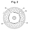
- the sensor plate 20 has three short projections 21, 22, 23 in the circumferential direction and a long projection 24 in the circumferential direction as shown FIG. 2 .
- the sensor plate 20 has a rim 25.
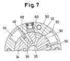
- the rotor 30 has a plurality of grooves for inserting the vanes 40 as shown in FIG. 4 to FIG. 7 .
- One side end of the housing 50 is fixed to a timing pulley 70 and the other side end of the housing 50 is fixed to a side plate 71 by a bolt 91. Therefore, the housing 50, the timing pulley 70 and the side plate 71 act in a body.
- the timing pulley 70 is transmitted rotational torque via a belt 72 (or a chain 72) from a crank shaft 83 which is rotated by the engine E.
- a pin 60 is able to connect with between the rotor 30 find the housing 50 when the rotor 30 is in phase with the housing 50.
- the exhaust cam shaft 10 has a plurality of cams (not shown). Each cam makes an exhaust valve open and close. There is a passage 11 which is formed in exhaust cam shaft 10 at its axial centre and extends in the axial direction. One end of the passage 11 communicates with the circular groove 14 through a passage 13. The circular groove 14 communicates with a passage 81 which is formed in the cylinder head 80 of the engine E. On the other hand, there are a plurality of passages 12 which are formed in the exhaust cam shaft 10 and located on a coaxial circle about the axial centre of the shaft 10 and which extend in parallel in the axial direction. One end of the passages 12 communicates with the circular groove 15. The circular groove 15 communicates with a passage 82 which is formed in the cylinder head 80 of an engine E.
- the fluid supplying device 100 comprises a changeover valve 101, a fluid pump 102 and a. controller 103.
- the changeover valve 101 is a. four port-three position type electromagnetic valve.
- the pump 102 may be a pump for lubricating the engine E.
- the passage 82 communicates with a port A of the changeover valve 101 and a passage 81 communicates with a part 8 of the changeover valve 101.
- a port P of the changeover valve 101 communicates with a discharge portion of the fluid pump 102 via a passage 105 and a port R of the changeover valve 101 communicates with a reservoir 104 via a passage 106.
- the position of the changeover valve 101 is controlled by the controller 103. in a first condition as shown in FIG.
- the discharged fluid from the pump 102 is supplied to the passage 82 and the passage 81 communicates with the reservoir 104, in a second condition all the ports A, B, P, R are interrupted; in a third condition 1 the discharged fluid from the pump 102 is supplied to the passage 81 and the passage 82 communicates with the reservoir 104) are selectively obtained.
- the controller 103 controls the above conditions of the changeover valve 101 based on parameter signals such as engine speed, the opening level of a throttle valve (not shown) and so on.
- a valve timing control mechanism V is mounted in the rotor 30 and the housing 50.
- the rotor 30 has a cylindrical shape.
- the housing 50 has an inner bore, 54 and is rotatably mounted on the outer circumferential surface of the rotor 30 so as to surround the rotor 30.
- the housing 50 has the same axial length as the rotor 30 and is provided with a plurality of grooves 51 which are outwardly extended from the inner bore 54 in the radial direction and which are separated in the circumferential direction at regular intervals
- the housing 50 is also provided with a plurality of holes 53 for penetration of the bolt 91. The holes 53 penetrate in the axial direction and are separated in the circumferential direction at regular intervals.
- a plurality of chambers RO which are separated in the circumferential direction at regular intervals and each of which has a pair of circumferentially opposed walls 55 and 56 are defined along the rotor 30, the housing 50, the timing pulley 70 and the side plate 71.
- the number of grooves 31 is equal to the number of chambers RO.
- Each of the grooves 31 extends inwardly therefrom in the radial direction.
- the grooves are located at regular intervals in the circumferential direction.
- the vanes that extend outwardly in the radial direction into the chambers RO are mounted in the grooves 31.
- each of the chambers RO is divided into a first pressure chamber R1 and a second pressure chamber R2, both of which are fluidtightly separated from each other.
- the housing 50 has a hole 52 which extends in the radial direction.
- the hole 52 is able to accommodate the pin 60 which is pushed towards the rotor 30 by a coil-spring 61.
- the coil-spring 61 is supported by a clip 63 through a retainer 62.
- the rotor 30 on its outer circumferential surface has a hole 32 which extends inwardly thereof in the radial direction so as to accommodate the pin 60.
- the rotor 30 is provided with a plurality of first passages 34, a plurality of second passages 36, and a passage 35.
- the first passages 34 and the passage 35 are in communication.
- One end of each of the first passages 34 communicates with the passage 11 and the other end of the first passages 34 communicates with each of the first chambers R1.
- one end of each of the second passages 36 communicates with the passage 12 and the other end of the second passages communicates with each of the second chambers R2.
- coil-spring 92 There is a coil-spring 92. One end of the coil-spring 92 is connected with the rotor 30 and the other end of the coil-spring 92 is connected with the side plate 71 which is fixed to the housing 50. The outer surface of the rim 25 of the sensor plate 20 guides the coil portion of the coil-spring 92 as shown in FIG. 1 .
- valve timing control device having the above structure
- the exhaust camshaft 10 is rotated counterclockwise by timing pulley 70. Thereby, exhaust valves (not shown) are opened and closed.
- the pressure of the fluid delivered from the oil pump 102 is increased. Fluid under the resulting pressure is supplied to the changeover valve 101.
- the changeover valve 101 is in the first condition as shown in FIG. 1 , fluid is supplied to the chambers R2 via the passage 82, the passage 12 and second passages 36.
- the vanes 40 are rotated in the counterclockwise direction, together with the rotor 30 and the exhaust cam shaft 10.
- the cam shaft 10 is advanced through an angle relative to the crank shaft 83.
- the vanes 40 are rotated in the clockwise direction by supplying fluid under pressure to the chambers R1 via the passage 81, the passage 11 and the first passages 34. Since the first passage 34 communicates with the passage 35, fluid under pressure supplied into the hole 32 urges the pin 60 fully into the hole 52 of the housing 50 as shown in FIG. 5 , thereby releasing the connection between the rotor 30 and the housing 50. With increasing pressure in the chamber R1, the vanes 40 are rotated in the clockwise direction as shown in FIG. 7 via the condition shown in FIG. 6 . During the retarding rotary movement of the vanes 40, fluid in each of chambers R2 is drained to the reservoir 104 through the passage 36, the passage 12, second passages 82 and the changeover valve 101.
- the fluid pressure in the chambers R1 and R2 is drained with the elapse of time through a non-illustrated clearance between the parts, for example, between the exhaust cam shaft 10 and the cylinder head 80. Therefore, the coil-spring urges the rotor 30 in the counterclockwise direction so as to fit the pin 60 into the hole 32 of the rotor 30.
- FIG. 8 illustrates a second embodiment, which specifically is a modified arrangement of a coil-spring 93.
- the coil-spring 93 is arranged within the housing 50 between the rotor 30 and the timing pulley 70.
- the timing pulley 70 has a cylindrical hollow 74.
- the cylindrical hollow 74 accommodates the coil-spring 93 which one end thereof is connected with the rotor 30 and which the other end thereof is connected with the timing pulley 70 which is fixed to the housing 50.
Landscapes
- Engineering & Computer Science (AREA)
- Mechanical Engineering (AREA)
- General Engineering & Computer Science (AREA)
- Valve Device For Special Equipments (AREA)
- Valve-Gear Or Valve Arrangements (AREA)
Claims (8)
- Dispositif de commande du calage des soupapes comprenant :un rotor (30) fixé sur un arbre à cames (10) d'un moteur (E) ;un élément de logement (50) monté en rotation sur l'arbre à cames (10) de façon à entourer le rotor (30) ;un moyen (70) destiné à entraîner l'élément de logement (50) à partir d'une sortie de rotation du moteur (E) ;une chambre (R0) définie entre l'élément de logement (50) et le rotor (30) et comportant une paire de parois circonférenciellement opposées (55-56) ;une vanne (40) montée sur le rotor (30) et s'étendant vers l'extérieur à partir de celui-ci dans la direction radiale dans la chambre (R0) de façon à diviser la chambre en une première chambre de pression (R1) et une deuxième chambre de pression (R2) ;un moyen d'alimentation en fluide (100) destiné à délivrer du fluide sous-pression sélectivement à l'une des première et deuxième chambres de pression (R1 et R2) établissant de ce fait un différentiel de pression entre lesdites chambres de pression (R1 et R2) de façon à effectuer une rotation relative entre le rotor (30) et l'élément de logement (50) ; etun moyen (60) destiné à bloquer le rotor (30) et l'élément de logement (50) dans une disposition angulaire relative pré-déterminée et pour libérer sélectivement cette mise en prise de blocage ;caractérisé en ce qu'un élément de ressort (92-93) est prévu à l'intérieur du dispositif pour solliciter le rotor (30) vers la position angulaire dans laquelle il est bloqué, dans lequel l'arbre à cames (10) commande une ou plusieurs soupapes d'échappement du moteur (E) et l'élément à ressort (92-93) agit pour solliciter le rotor (30) dans un état de calage de soupape avancé.
- Dispositif de commande du calage des soupapes selon la revendication 1, dans lequel l'élément à ressort (92-93) est un ressort hélicoïdal (92-93) et une extrémité du ressort hélicoïdal est fixée au rotor (30), et l'autre extrémité du ressort hélicoïdal est fixée à l'élément de logement (50).
- Dispositif de commande du calage des soupapes selon la revendication 2, dans lequel le rotor (30) et l'élément de logement (50) sont disposés entre le ressort hélicoïdal (92) et le moteur.
- Dispositif de commande du calage des soupapes selon la revendication 3, dans lequel le ressort hélicoïdal est guidé par une plaque de capteur (20) qui est disposée au niveau de l'extrémité de l'arbre à cames (10).
- Dispositif de calage des soupapes selon la revendication 2, dans lequel le ressort hélicoïdal (92-93) est un ressort de torsion.
- Dispositif de calage des soupapes selon la revendication 2., dans lequel le ressort hélicoïdal (92-93) comporte un axe coïncidant avec l'axe de l'arbre à cames (10).
- Dispositif de commande du calage des soupapes selon la revendication 6, dans lequel le ressort hélicoïdal (92) est un ressort hélicoïdal formé cylindriquement dont une extrémité axiale est placée dans un évidement cylindrique dans le rotor (30) et est ancrée au rotor, et dont l'autre extrémité axiale est placée dans un espace cylindrique entre un élément (71) attaché à l'élément de logement (50) et un élément (25) attaché au rotor (30).
- Dispositif de commande du calage des soupapes selon la revendication 6, dans lequel le ressort hélicoïdal (93) est un ressort hélicoïdal formé cylindriquement qui est situé dans un creux cylindrique (74) dans le moyen d'entraînement (70).
Priority Applications (2)
| Application Number | Priority Date | Filing Date | Title |
|---|---|---|---|
| EP10010241.7A EP2320037B8 (fr) | 1996-03-28 | 1997-03-26 | Dephaseur d'arbre à cames |
| EP01106890A EP1128028B8 (fr) | 1996-03-28 | 1997-03-26 | Dispositif de commande du calage des soupapes |
Applications Claiming Priority (6)
| Application Number | Priority Date | Filing Date | Title |
|---|---|---|---|
| JP7482396 | 1996-03-28 | ||
| JP74823/96 | 1996-03-28 | ||
| JP07482396A JP3365199B2 (ja) | 1996-03-28 | 1996-03-28 | 弁開閉時期制御装置 |
| JP63247/97 | 1997-03-17 | ||
| JP6324797 | 1997-03-17 | ||
| JP6324797A JP3812692B2 (ja) | 1997-03-17 | 1997-03-17 | 弁開閉時期制御装置 |
Related Child Applications (1)
| Application Number | Title | Priority Date | Filing Date |
|---|---|---|---|
| EP01106890A Division EP1128028B8 (fr) | 1996-03-28 | 1997-03-26 | Dispositif de commande du calage des soupapes |
Publications (3)
| Publication Number | Publication Date |
|---|---|
| EP0806550A1 EP0806550A1 (fr) | 1997-11-12 |
| EP0806550B1 EP0806550B1 (fr) | 2001-12-19 |
| EP0806550B2 true EP0806550B2 (fr) | 2008-08-20 |
Family
ID=26404328
Family Applications (3)
| Application Number | Title | Priority Date | Filing Date |
|---|---|---|---|
| EP01106890A Expired - Lifetime EP1128028B8 (fr) | 1996-03-28 | 1997-03-26 | Dispositif de commande du calage des soupapes |
| EP10010241.7A Expired - Lifetime EP2320037B8 (fr) | 1996-03-28 | 1997-03-26 | Dephaseur d'arbre à cames |
| EP97302104A Expired - Lifetime EP0806550B2 (fr) | 1996-03-28 | 1997-03-26 | Dispositif de commande du calage des soupapes |
Family Applications Before (2)
| Application Number | Title | Priority Date | Filing Date |
|---|---|---|---|
| EP01106890A Expired - Lifetime EP1128028B8 (fr) | 1996-03-28 | 1997-03-26 | Dispositif de commande du calage des soupapes |
| EP10010241.7A Expired - Lifetime EP2320037B8 (fr) | 1996-03-28 | 1997-03-26 | Dephaseur d'arbre à cames |
Country Status (3)
| Country | Link |
|---|---|
| US (1) | US5775279A (fr) |
| EP (3) | EP1128028B8 (fr) |
| DE (1) | DE69709231T3 (fr) |
Families Citing this family (56)
| Publication number | Priority date | Publication date | Assignee | Title |
|---|---|---|---|---|
| JP3116858B2 (ja) * | 1996-11-29 | 2000-12-11 | トヨタ自動車株式会社 | 内燃機関のバルブタイミング可変機構 |
| US6158404A (en) | 1997-02-26 | 2000-12-12 | Aft Atlas Fahrzeugtechnik Gmbh | Apparatus for regulating the operation of an adjusting device |
| DE19716203A1 (de) * | 1997-04-18 | 1998-10-22 | Schaeffler Waelzlager Ohg | Vorrichtung zum Verändern der Öffnungs- und Schließzeiten von Gaswechselventilen einer Brennkraftmaschine |
| JP3760568B2 (ja) * | 1997-06-05 | 2006-03-29 | アイシン精機株式会社 | 弁開閉時期制御装置 |
| JP3760566B2 (ja) * | 1997-06-05 | 2006-03-29 | アイシン精機株式会社 | 弁開閉時期制御装置 |
| DE19723945A1 (de) * | 1997-06-06 | 1998-12-10 | Schaeffler Waelzlager Ohg | Vorrichtung zum Verändern der Öffnungs- und Schließzeiten von Gaswechselventilen einer Brennkraftmaschine |
| DE19724989A1 (de) * | 1997-06-13 | 1998-12-17 | Schaeffler Waelzlager Ohg | Vorrichtung zum Verändern der Steuerzeiten in einer Brennkraftmaschine |
| JP3824110B2 (ja) * | 1997-06-30 | 2006-09-20 | アイシン精機株式会社 | 弁開閉時期制御装置 |
| JP3801747B2 (ja) * | 1997-09-29 | 2006-07-26 | アイシン精機株式会社 | 弁開閉時期制御装置 |
| JP3846605B2 (ja) * | 1997-10-30 | 2006-11-15 | アイシン精機株式会社 | 弁開閉時期制御装置 |
| DE19854891C2 (de) * | 1997-11-28 | 2003-02-06 | Aisin Seiki | Ventilzeitsteuervorrichtung |
| DE19755495A1 (de) * | 1997-12-13 | 1999-06-17 | Schaeffler Waelzlager Ohg | Verriegelungseinrichtung für eine Vorrichtung zum Verändern der Steuerzeiten von Gaswechselventilen einer Brennkraftmaschine |
| DE19756017A1 (de) * | 1997-12-17 | 1999-06-24 | Porsche Ag | Einrichtung zur relativen Drehlagenänderung einer Welle zum Antriebsrad |
| JP3815014B2 (ja) * | 1997-12-24 | 2006-08-30 | アイシン精機株式会社 | 弁開閉時期制御装置 |
| JP4147435B2 (ja) * | 1998-01-30 | 2008-09-10 | アイシン精機株式会社 | 弁開閉時期制御装置 |
| US6311654B1 (en) | 1998-07-29 | 2001-11-06 | Denso Corporation | Valve timing adjusting device |
| US5924407A (en) * | 1998-07-29 | 1999-07-20 | Navistar International Transportation Corp. | Commanded, rail-pressure-based, variable injector boost current duration |
| JP4158185B2 (ja) | 1999-12-15 | 2008-10-01 | 株式会社デンソー | バルブタイミング調整装置 |
| US6412462B1 (en) | 2000-01-18 | 2002-07-02 | Delphi Technologies, Inc. | Cam phaser apparatus having a stator integral with a back plate or a front cover plate |
| DE10103876B4 (de) * | 2000-01-31 | 2005-12-01 | Aisin Seiki K.K., Kariya | Ventilsteuerzeitverstellvorrichtung für Verbrennungsmotoren |
| DE10007200A1 (de) | 2000-02-17 | 2001-08-23 | Schaeffler Waelzlager Ohg | Vorrichtung zum Verändern der Steuerzeiten von Gaswechselventilen einer Brennkraftmaschine |
| JP4240756B2 (ja) * | 2000-05-10 | 2009-03-18 | アイシン精機株式会社 | 弁開閉時期制御装置 |
| JP4032288B2 (ja) * | 2002-03-28 | 2008-01-16 | アイシン精機株式会社 | 弁開閉時期制御装置 |
| US6871620B2 (en) * | 2002-04-09 | 2005-03-29 | Ford Global Technologies, Llc | Variable cam timing unit oil supply arrangement |
| DE102004028869A1 (de) * | 2004-06-15 | 2006-01-05 | Ina-Schaeffler Kg | Brennkraftmaschine mit einer hydraulischen Vorrichtung zur Drehwinkelverstellung einer Nockenwelle gegenüber einer Kurbelwelle |
| US7305949B2 (en) * | 2005-08-18 | 2007-12-11 | Delphi Technologies, Inc. | Stamped target wheel for a camshaft phaser |
| DE102005060111A1 (de) * | 2005-12-16 | 2007-07-05 | Schaeffler Kg | Nockenwellenverstellerzuleitung |
| DE102006022219B4 (de) * | 2006-05-11 | 2008-01-03 | Hydraulik-Ring Gmbh | Leckagedichter Nockenwellenversteller mit Rückstellfeder |
| DE102007020524A1 (de) | 2007-05-02 | 2008-11-06 | Schaeffler Kg | Nockenwellenversteller für eine Brennkraftmaschine mit einem integrierten Triggerrad |
| DE102007041552A1 (de) | 2007-08-31 | 2009-03-05 | Schaeffler Kg | Vorrichtung zur variablen Einstellung der Steuerzeiten von Gaswechselventilen einer Brennkraftmaschine |
| DE102007056685A1 (de) | 2007-11-24 | 2009-05-28 | Schaeffler Kg | Vorrichtung zur variablen Einstellung der Steuerzeiten von Gaswechselventilen einer Brennkraftmaschine |
| DE102007056683A1 (de) * | 2007-11-24 | 2009-05-28 | Schaeffler Kg | Vorrichtung zur variablen Einstellung der Steuerzeiten von Gaswechselventilen einer Brennkraftmaschine |
| JP4851475B2 (ja) * | 2008-02-08 | 2012-01-11 | 株式会社デンソー | バルブタイミング調整装置 |
| DE102008017455A1 (de) | 2008-04-05 | 2009-10-08 | Schaeffler Kg | Nockenwellenverstelleinrichtung |
| DE102008017688A1 (de) | 2008-04-08 | 2009-10-15 | Schaeffler Kg | Vorrichtung zur variablen Einstellung der Steuerzeiten von Gaswechselventilen einer Brennkraftmaschine |
| DE102008037997B4 (de) | 2008-08-16 | 2019-08-22 | Schaeffler Technologies AG & Co. KG | Vorrichtung zur variablen Einstellung der Steuerzeiten von Gaswechselventilen einer Brennkraftmaschine |
| DE102008037996A1 (de) | 2008-08-16 | 2010-02-18 | Schaeffler Kg | Vorrichtung zur variablen Einstellung der Steuerzeiten von Gaswechselventilen einer Brennkraftmaschine |
| DE102009034011B4 (de) | 2008-10-07 | 2018-04-05 | Schaeffler Technologies AG & Co. KG | Druckspeicher zur Unterstützung der Druckmittelversorgung eines Nockenwellenverstellers einer Brennkraftmaschine |
| DE102009016186A1 (de) | 2009-04-03 | 2010-10-14 | Schaeffler Technologies Gmbh & Co. Kg | Vorrichtung zur variablen Einstellung der Steuerzeiten von Gaswechselventilen einer Brennkraftmaschine |
| DE102009030201A1 (de) | 2009-06-24 | 2010-12-30 | Schaeffler Technologies Gmbh & Co. Kg | Vorrichtung zur variablen Einstellung der Steuerzeiten von Gaswechselventilen einer Brennkraftmaschine |
| DE102009042202A1 (de) | 2009-09-18 | 2011-04-14 | Schaeffler Technologies Gmbh & Co. Kg | Vorrichtung zur variablen Einstellung der Steuerzeiten von Gaswechselventilen einer Brennkraftmaschine |
| DE102009049461A1 (de) | 2009-10-15 | 2011-04-21 | Schaeffler Technologies Gmbh & Co. Kg | Volumenspeicher |
| DE102009049459A1 (de) | 2009-10-15 | 2011-04-21 | Schaeffler Technologies Gmbh & Co. Kg | Volumenspeicher |
| DE102009056024A1 (de) | 2009-11-27 | 2011-06-01 | Schaeffler Technologies Gmbh & Co. Kg | Vorrichtung zur variablen Einstellung der Steuerzeiten von Gaswechselventilen einer Brennkraftmaschine |
| DE102009056020A1 (de) | 2009-11-27 | 2011-06-01 | Schaeffler Technologies Gmbh & Co. Kg | Vorrichtung zur variablen Einstellung der Steuerzeiten von Gaswechselventilen einer Brennkraftmaschine |
| DE102009056018A1 (de) | 2009-11-27 | 2011-07-07 | Schaeffler Technologies GmbH & Co. KG, 91074 | Vorrichtung zur variablen Einstellung der Steuerzeiten von Gaswechselventilen einer Brennkraftmaschine |
| DE102009056021A1 (de) | 2009-11-27 | 2011-06-01 | Schaeffler Technologies Gmbh & Co. Kg | Vorrichtung zur varibalen Einstellung der Steuerzeiten von Gaswechselventilen einer Brennkraftmaschine |
| DE102009056023A1 (de) | 2009-11-27 | 2011-06-01 | Schaeffler Technologies Gmbh & Co. Kg | Vorrichtung zur variablen Einstellung der Steuerzeiten von Gaswechselventilen einer Brennkraftmaschine |
| DE102010013928A1 (de) | 2010-04-06 | 2011-10-06 | Schaeffler Technologies Gmbh & Co. Kg | Rotoreinheit für einen Nockenwellenversteller sowie Nockenwellenverstellsystem |
| JP5505257B2 (ja) * | 2010-10-27 | 2014-05-28 | アイシン精機株式会社 | 弁開閉時期制御装置 |
| DE102011003991A1 (de) | 2011-02-11 | 2012-08-16 | Schaeffler Technologies Gmbh & Co. Kg | Nockenwellenversteller mit einem Druckspeicher |
| DE102011004539A1 (de) * | 2011-02-22 | 2012-08-23 | Schwäbische Hüttenwerke Automotive GmbH | Nockenwellen-Phasensteller mit verbesserter Verriegelungseinrichtung |
| DE102011007883A1 (de) | 2011-04-21 | 2012-10-25 | Schaeffler Technologies AG & Co. KG | Nockenwellenversteller |
| DE102012008609A1 (de) | 2012-04-27 | 2013-10-31 | Volkswagen Aktiengesellschaft | Nockenwellenverstellvorrichtung |
| DE102013219075B4 (de) | 2013-09-23 | 2020-11-26 | Schaeffler Technologies AG & Co. KG | Multiverriegelung eines Nockenwellenverstellers |
| DE102013220322B4 (de) * | 2013-10-09 | 2020-11-26 | Schaeffler Technologies AG & Co. KG | Nockenwellenverstelleinrichtung |
Citations (5)
| Publication number | Priority date | Publication date | Assignee | Title |
|---|---|---|---|---|
| DE3810804A1 (de) † | 1988-03-30 | 1989-10-19 | Daimler Benz Ag | Vorrichtung zur relativen winkelverstellung zwischen zwei in antriebsverbindung stehenden wellen |
| DE3825074C1 (fr) † | 1988-07-23 | 1989-10-19 | Daimler-Benz Aktiengesellschaft, 7000 Stuttgart, De | |
| DE3907077A1 (de) † | 1989-03-04 | 1990-09-06 | Daimler Benz Ag | Einrichtung zur relativen winkelverstellung einer nockenwelle von brennkraftmaschinen |
| DE4218081A1 (de) † | 1992-06-01 | 1993-12-02 | Schaeffler Waelzlager Kg | Verstellbarer, geteilter Kolben |
| EP0652354A1 (fr) † | 1993-10-06 | 1995-05-10 | Carraro S.P.A. | Variateur de calage entre le vilebrequin et l'arbre à cames d'un moteur à combustion interne |
Family Cites Families (8)
| Publication number | Priority date | Publication date | Assignee | Title |
|---|---|---|---|---|
| JPS5339938B2 (fr) * | 1973-10-05 | 1978-10-24 | ||
| DE3616234A1 (de) * | 1986-05-14 | 1987-11-19 | Bayerische Motoren Werke Ag | Vorrichtung zur relativen drehlagenaenderung zweier in antriebsverbindung stehender wellen, insbesondere zwischen in einem maschinengehaeuse einer brennkraftmaschine gelagerten kurbelwelle und nockenwelle |
| JPH0192504A (ja) | 1987-09-30 | 1989-04-11 | Aisin Seiki Co Ltd | 弁開閉時期制御装置 |
| DE3922962A1 (de) * | 1989-07-12 | 1991-01-17 | Audi Ag | Antriebsvorrichtung fuer eine nockenwelle einer brennkraftmaschine |
| DE3930157A1 (de) * | 1989-09-09 | 1991-03-21 | Bosch Gmbh Robert | Einrichtung zur verstellung der drehwinkelzuordnung einer nockenwelle zu ihrem antriebselement |
| US5046460A (en) * | 1989-10-16 | 1991-09-10 | Borg-Warner Automotive Transmission & Engine Components Corporation | Variable camshaft timing for internal combustion engine |
| JP3076390B2 (ja) * | 1991-03-26 | 2000-08-14 | マツダ株式会社 | エンジンのカムタイミング制御装置 |
| US5666914A (en) * | 1994-05-13 | 1997-09-16 | Nippondenso Co., Ltd. | Vane type angular phase adjusting device |
-
1997
- 1997-03-26 EP EP01106890A patent/EP1128028B8/fr not_active Expired - Lifetime
- 1997-03-26 DE DE69709231T patent/DE69709231T3/de not_active Expired - Lifetime
- 1997-03-26 EP EP10010241.7A patent/EP2320037B8/fr not_active Expired - Lifetime
- 1997-03-26 EP EP97302104A patent/EP0806550B2/fr not_active Expired - Lifetime
- 1997-03-28 US US08/828,937 patent/US5775279A/en not_active Expired - Lifetime
Patent Citations (5)
| Publication number | Priority date | Publication date | Assignee | Title |
|---|---|---|---|---|
| DE3810804A1 (de) † | 1988-03-30 | 1989-10-19 | Daimler Benz Ag | Vorrichtung zur relativen winkelverstellung zwischen zwei in antriebsverbindung stehenden wellen |
| DE3825074C1 (fr) † | 1988-07-23 | 1989-10-19 | Daimler-Benz Aktiengesellschaft, 7000 Stuttgart, De | |
| DE3907077A1 (de) † | 1989-03-04 | 1990-09-06 | Daimler Benz Ag | Einrichtung zur relativen winkelverstellung einer nockenwelle von brennkraftmaschinen |
| DE4218081A1 (de) † | 1992-06-01 | 1993-12-02 | Schaeffler Waelzlager Kg | Verstellbarer, geteilter Kolben |
| EP0652354A1 (fr) † | 1993-10-06 | 1995-05-10 | Carraro S.P.A. | Variateur de calage entre le vilebrequin et l'arbre à cames d'un moteur à combustion interne |
Also Published As
| Publication number | Publication date |
|---|---|
| EP2320037B8 (fr) | 2013-11-13 |
| EP1128028A3 (fr) | 2003-02-19 |
| DE69709231T3 (de) | 2009-01-08 |
| EP2320037A1 (fr) | 2011-05-11 |
| EP2320037B1 (fr) | 2013-07-24 |
| EP0806550A1 (fr) | 1997-11-12 |
| EP1128028A2 (fr) | 2001-08-29 |
| EP0806550B1 (fr) | 2001-12-19 |
| EP1128028B1 (fr) | 2012-01-25 |
| US5775279A (en) | 1998-07-07 |
| DE69709231D1 (de) | 2002-01-31 |
| EP1128028B8 (fr) | 2012-11-07 |
| DE69709231T2 (de) | 2002-08-08 |
Similar Documents
| Publication | Publication Date | Title |
|---|---|---|
| EP0806550B2 (fr) | Dispositif de commande du calage des soupapes | |
| EP0807747B1 (fr) | Dispositif de commande du calage des soupapes | |
| KR100242589B1 (ko) | 내연기관의 가변밸브 타이밍기구 | |
| EP1229216B1 (fr) | Dispositif de commande de soupape | |
| EP0821138B1 (fr) | Dispositifs de commande du calage des soupapes | |
| US6105543A (en) | Valve timing control device | |
| US8689747B2 (en) | Valve timing control device | |
| EP0818610B1 (fr) | Dispositifs de commande du calage des soupapes | |
| US6062182A (en) | Valve timing control device | |
| US6334414B1 (en) | Valve timing adjusting apparatus | |
| EP0781899B1 (fr) | Dispositif de commande du calage des soupapes | |
| JPH1113432A (ja) | 弁開閉時期制御装置 | |
| JP2001090512A (ja) | 弁開閉時期制御装置 | |
| JPH09250310A (ja) | 内燃機関のバルブタイミング変更装置 | |
| JP3845986B2 (ja) | 弁開閉時期制御装置 | |
| JP4016527B2 (ja) | 弁開閉時期制御装置 | |
| JP3744666B2 (ja) | 弁開閉時期制御装置 | |
| JP4538937B2 (ja) | 弁開閉時期制御装置 | |
| JP3812692B2 (ja) | 弁開閉時期制御装置 | |
| JPH10159515A (ja) | 内燃機関のバルブタイミング制御装置 | |
| JP3873466B2 (ja) | 弁開閉時期制御装置 | |
| JP4026286B2 (ja) | 弁開閉時期制御装置 | |
| JP3058096B2 (ja) | 内燃機関のバルブタイミング可変装置 | |
| JPH10103030A (ja) | 弁開閉時期制御装置 | |
| JP3221336B2 (ja) | 内燃機関のバルブタイミング制御装置 |
Legal Events
| Date | Code | Title | Description |
|---|---|---|---|
| PUAI | Public reference made under article 153(3) epc to a published international application that has entered the european phase |
Free format text: ORIGINAL CODE: 0009012 |
|
| AK | Designated contracting states |
Kind code of ref document: A1 Designated state(s): DE FR GB IT |
|
| 17P | Request for examination filed |
Effective date: 19971122 |
|
| 17Q | First examination report despatched |
Effective date: 19980624 |
|
| GRAG | Despatch of communication of intention to grant |
Free format text: ORIGINAL CODE: EPIDOS AGRA |
|
| GRAG | Despatch of communication of intention to grant |
Free format text: ORIGINAL CODE: EPIDOS AGRA |
|
| GRAG | Despatch of communication of intention to grant |
Free format text: ORIGINAL CODE: EPIDOS AGRA |
|
| GRAH | Despatch of communication of intention to grant a patent |
Free format text: ORIGINAL CODE: EPIDOS IGRA |
|
| GRAH | Despatch of communication of intention to grant a patent |
Free format text: ORIGINAL CODE: EPIDOS IGRA |
|
| GRAA | (expected) grant |
Free format text: ORIGINAL CODE: 0009210 |
|
| AK | Designated contracting states |
Kind code of ref document: B1 Designated state(s): DE FR GB IT |
|
| PG25 | Lapsed in a contracting state [announced via postgrant information from national office to epo] |
Ref country code: IT Free format text: LAPSE BECAUSE OF FAILURE TO SUBMIT A TRANSLATION OF THE DESCRIPTION OR TO PAY THE FEE WITHIN THE PRESCRIBED TIME-LIMIT;WARNING: LAPSES OF ITALIAN PATENTS WITH EFFECTIVE DATE BEFORE 2007 MAY HAVE OCCURRED AT ANY TIME BEFORE 2007. THE CORRECT EFFECTIVE DATE MAY BE DIFFERENT FROM THE ONE RECORDED. Effective date: 20011219 |
|
| REG | Reference to a national code |
Ref country code: GB Ref legal event code: IF02 |
|
| REF | Corresponds to: |
Ref document number: 69709231 Country of ref document: DE Date of ref document: 20020131 |
|
| ET | Fr: translation filed | ||
| PLBI | Opposition filed |
Free format text: ORIGINAL CODE: 0009260 |
|
| PLBQ | Unpublished change to opponent data |
Free format text: ORIGINAL CODE: EPIDOS OPPO |
|
| PLAB | Opposition data, opponent's data or that of the opponent's representative modified |
Free format text: ORIGINAL CODE: 0009299OPPO |
|
| PLBI | Opposition filed |
Free format text: ORIGINAL CODE: 0009260 |
|
| 26 | Opposition filed |
Opponent name: INA-SCHAEFFLER KG Effective date: 20020820 |
|
| R26 | Opposition filed (corrected) |
Opponent name: INA-SCHAEFFLER KG * 20020913 DAIMLERCHRYSLER AG IN Effective date: 20020820 |
|
| PLBF | Reply of patent proprietor to notice(s) of opposition |
Free format text: ORIGINAL CODE: EPIDOS OBSO |
|
| PLBF | Reply of patent proprietor to notice(s) of opposition |
Free format text: ORIGINAL CODE: EPIDOS OBSO |
|
| PLBF | Reply of patent proprietor to notice(s) of opposition |
Free format text: ORIGINAL CODE: EPIDOS OBSO |
|
| PLBQ | Unpublished change to opponent data |
Free format text: ORIGINAL CODE: EPIDOS OPPO |
|
| PLAB | Opposition data, opponent's data or that of the opponent's representative modified |
Free format text: ORIGINAL CODE: 0009299OPPO |
|
| R26 | Opposition filed (corrected) |
Opponent name: DAIMLERCHRYSLER AGINTELLECTUAL PROPERTY MANAGEMENT Effective date: 20020913 Opponent name: INA-SCHAEFFLER KG Effective date: 20020820 |
|
| APAY | Date of receipt of notice of appeal deleted |
Free format text: ORIGINAL CODE: EPIDOSDNOA2O |
|
| APBP | Date of receipt of notice of appeal recorded |
Free format text: ORIGINAL CODE: EPIDOSNNOA2O |
|
| APAY | Date of receipt of notice of appeal deleted |
Free format text: ORIGINAL CODE: EPIDOSDNOA2O |
|
| APBP | Date of receipt of notice of appeal recorded |
Free format text: ORIGINAL CODE: EPIDOSNNOA2O |
|
| APBP | Date of receipt of notice of appeal recorded |
Free format text: ORIGINAL CODE: EPIDOSNNOA2O |
|
| APBQ | Date of receipt of statement of grounds of appeal recorded |
Free format text: ORIGINAL CODE: EPIDOSNNOA3O |
|
| APBQ | Date of receipt of statement of grounds of appeal recorded |
Free format text: ORIGINAL CODE: EPIDOSNNOA3O |
|
| APAA | Appeal reference recorded |
Free format text: ORIGINAL CODE: EPIDOS REFN |
|
| APAH | Appeal reference modified |
Free format text: ORIGINAL CODE: EPIDOSCREFNO |
|
| PLAB | Opposition data, opponent's data or that of the opponent's representative modified |
Free format text: ORIGINAL CODE: 0009299OPPO |
|
| R26 | Opposition filed (corrected) |
Opponent name: DAIMLERCHRYSLER AG I Effective date: 20020913 Opponent name: SCHAEFFLER KG Effective date: 20020820 |
|
| APBU | Appeal procedure closed |
Free format text: ORIGINAL CODE: EPIDOSNNOA9O |
|
| APBW | Interlocutory revision of appeal recorded |
Free format text: ORIGINAL CODE: EPIDOSNIRAPO |
|
| APAH | Appeal reference modified |
Free format text: ORIGINAL CODE: EPIDOSCREFNO |
|
| APBP | Date of receipt of notice of appeal recorded |
Free format text: ORIGINAL CODE: EPIDOSNNOA2O |
|
| APBU | Appeal procedure closed |
Free format text: ORIGINAL CODE: EPIDOSNNOA9O |
|
| PUAH | Patent maintained in amended form |
Free format text: ORIGINAL CODE: 0009272 |
|
| STAA | Information on the status of an ep patent application or granted ep patent |
Free format text: STATUS: PATENT MAINTAINED AS AMENDED |
|
| 27A | Patent maintained in amended form |
Effective date: 20080820 |
|
| AK | Designated contracting states |
Kind code of ref document: B2 Designated state(s): DE FR GB IT |
|
| REG | Reference to a national code |
Ref country code: FR Ref legal event code: PLFP Year of fee payment: 20 |
|
| PGFP | Annual fee paid to national office [announced via postgrant information from national office to epo] |
Ref country code: DE Payment date: 20160322 Year of fee payment: 20 |
|
| PGFP | Annual fee paid to national office [announced via postgrant information from national office to epo] |
Ref country code: FR Payment date: 20160208 Year of fee payment: 20 Ref country code: GB Payment date: 20160323 Year of fee payment: 20 |
|
| REG | Reference to a national code |
Ref country code: DE Ref legal event code: R071 Ref document number: 69709231 Country of ref document: DE |
|
| REG | Reference to a national code |
Ref country code: GB Ref legal event code: PE20 Expiry date: 20170325 |
|
| PG25 | Lapsed in a contracting state [announced via postgrant information from national office to epo] |
Ref country code: GB Free format text: LAPSE BECAUSE OF EXPIRATION OF PROTECTION Effective date: 20170325 |