EP0715099A2 - Système de commande de la force d'entraînement d'un véhicule - Google Patents
Système de commande de la force d'entraînement d'un véhicule Download PDFInfo
- Publication number
- EP0715099A2 EP0715099A2 EP96102437A EP96102437A EP0715099A2 EP 0715099 A2 EP0715099 A2 EP 0715099A2 EP 96102437 A EP96102437 A EP 96102437A EP 96102437 A EP96102437 A EP 96102437A EP 0715099 A2 EP0715099 A2 EP 0715099A2
- Authority
- EP
- European Patent Office
- Prior art keywords
- shift
- torque
- line pressure
- engine
- gear
- Prior art date
- Legal status (The legal status is an assumption and is not a legal conclusion. Google has not performed a legal analysis and makes no representation as to the accuracy of the status listed.)
- Granted
Links
Images


Classifications
-
- B—PERFORMING OPERATIONS; TRANSPORTING
- B60—VEHICLES IN GENERAL
- B60K—ARRANGEMENT OR MOUNTING OF PROPULSION UNITS OR OF TRANSMISSIONS IN VEHICLES; ARRANGEMENT OR MOUNTING OF PLURAL DIVERSE PRIME-MOVERS IN VEHICLES; AUXILIARY DRIVES FOR VEHICLES; INSTRUMENTATION OR DASHBOARDS FOR VEHICLES; ARRANGEMENTS IN CONNECTION WITH COOLING, AIR INTAKE, GAS EXHAUST OR FUEL SUPPLY OF PROPULSION UNITS IN VEHICLES
- B60K20/00—Arrangement or mounting of change-speed gearing control devices in vehicles
-
- B—PERFORMING OPERATIONS; TRANSPORTING
- B60—VEHICLES IN GENERAL
- B60W—CONJOINT CONTROL OF VEHICLE SUB-UNITS OF DIFFERENT TYPE OR DIFFERENT FUNCTION; CONTROL SYSTEMS SPECIALLY ADAPTED FOR HYBRID VEHICLES; ROAD VEHICLE DRIVE CONTROL SYSTEMS FOR PURPOSES NOT RELATED TO THE CONTROL OF A PARTICULAR SUB-UNIT
- B60W10/00—Conjoint control of vehicle sub-units of different type or different function
- B60W10/04—Conjoint control of vehicle sub-units of different type or different function including control of propulsion units
- B60W10/06—Conjoint control of vehicle sub-units of different type or different function including control of propulsion units including control of combustion engines
-
- B—PERFORMING OPERATIONS; TRANSPORTING
- B60—VEHICLES IN GENERAL
- B60K—ARRANGEMENT OR MOUNTING OF PROPULSION UNITS OR OF TRANSMISSIONS IN VEHICLES; ARRANGEMENT OR MOUNTING OF PLURAL DIVERSE PRIME-MOVERS IN VEHICLES; AUXILIARY DRIVES FOR VEHICLES; INSTRUMENTATION OR DASHBOARDS FOR VEHICLES; ARRANGEMENTS IN CONNECTION WITH COOLING, AIR INTAKE, GAS EXHAUST OR FUEL SUPPLY OF PROPULSION UNITS IN VEHICLES
- B60K17/00—Arrangement or mounting of transmissions in vehicles
-
- B—PERFORMING OPERATIONS; TRANSPORTING
- B60—VEHICLES IN GENERAL
- B60W—CONJOINT CONTROL OF VEHICLE SUB-UNITS OF DIFFERENT TYPE OR DIFFERENT FUNCTION; CONTROL SYSTEMS SPECIALLY ADAPTED FOR HYBRID VEHICLES; ROAD VEHICLE DRIVE CONTROL SYSTEMS FOR PURPOSES NOT RELATED TO THE CONTROL OF A PARTICULAR SUB-UNIT
- B60W10/00—Conjoint control of vehicle sub-units of different type or different function
- B60W10/04—Conjoint control of vehicle sub-units of different type or different function including control of propulsion units
-
- B—PERFORMING OPERATIONS; TRANSPORTING
- B60—VEHICLES IN GENERAL
- B60W—CONJOINT CONTROL OF VEHICLE SUB-UNITS OF DIFFERENT TYPE OR DIFFERENT FUNCTION; CONTROL SYSTEMS SPECIALLY ADAPTED FOR HYBRID VEHICLES; ROAD VEHICLE DRIVE CONTROL SYSTEMS FOR PURPOSES NOT RELATED TO THE CONTROL OF A PARTICULAR SUB-UNIT
- B60W10/00—Conjoint control of vehicle sub-units of different type or different function
- B60W10/10—Conjoint control of vehicle sub-units of different type or different function including control of change-speed gearings
- B60W10/11—Stepped gearings
- B60W10/115—Stepped gearings with planetary gears
-
- B—PERFORMING OPERATIONS; TRANSPORTING
- B60—VEHICLES IN GENERAL
- B60W—CONJOINT CONTROL OF VEHICLE SUB-UNITS OF DIFFERENT TYPE OR DIFFERENT FUNCTION; CONTROL SYSTEMS SPECIALLY ADAPTED FOR HYBRID VEHICLES; ROAD VEHICLE DRIVE CONTROL SYSTEMS FOR PURPOSES NOT RELATED TO THE CONTROL OF A PARTICULAR SUB-UNIT
- B60W30/00—Purposes of road vehicle drive control systems not related to the control of a particular sub-unit, e.g. of systems using conjoint control of vehicle sub-units, or advanced driver assistance systems for ensuring comfort, stability and safety or drive control systems for propelling or retarding the vehicle
- B60W30/18—Propelling the vehicle
- B60W30/1819—Propulsion control with control means using analogue circuits, relays or mechanical links
-
- B—PERFORMING OPERATIONS; TRANSPORTING
- B60—VEHICLES IN GENERAL
- B60W—CONJOINT CONTROL OF VEHICLE SUB-UNITS OF DIFFERENT TYPE OR DIFFERENT FUNCTION; CONTROL SYSTEMS SPECIALLY ADAPTED FOR HYBRID VEHICLES; ROAD VEHICLE DRIVE CONTROL SYSTEMS FOR PURPOSES NOT RELATED TO THE CONTROL OF A PARTICULAR SUB-UNIT
- B60W30/00—Purposes of road vehicle drive control systems not related to the control of a particular sub-unit, e.g. of systems using conjoint control of vehicle sub-units, or advanced driver assistance systems for ensuring comfort, stability and safety or drive control systems for propelling or retarding the vehicle
- B60W30/18—Propelling the vehicle
- B60W30/19—Improvement of gear change, e.g. by synchronisation or smoothing gear shift
-
- F—MECHANICAL ENGINEERING; LIGHTING; HEATING; WEAPONS; BLASTING
- F16—ENGINEERING ELEMENTS AND UNITS; GENERAL MEASURES FOR PRODUCING AND MAINTAINING EFFECTIVE FUNCTIONING OF MACHINES OR INSTALLATIONS; THERMAL INSULATION IN GENERAL
- F16H—GEARING
- F16H61/00—Control functions within control units of change-speed- or reversing-gearings for conveying rotary motion ; Control of exclusively fluid gearing, friction gearing, gearings with endless flexible members or other particular types of gearing
- F16H61/04—Smoothing ratio shift
- F16H61/0437—Smoothing ratio shift by using electrical signals
-
- F—MECHANICAL ENGINEERING; LIGHTING; HEATING; WEAPONS; BLASTING
- F16—ENGINEERING ELEMENTS AND UNITS; GENERAL MEASURES FOR PRODUCING AND MAINTAINING EFFECTIVE FUNCTIONING OF MACHINES OR INSTALLATIONS; THERMAL INSULATION IN GENERAL
- F16H—GEARING
- F16H61/00—Control functions within control units of change-speed- or reversing-gearings for conveying rotary motion ; Control of exclusively fluid gearing, friction gearing, gearings with endless flexible members or other particular types of gearing
- F16H61/04—Smoothing ratio shift
- F16H61/06—Smoothing ratio shift by controlling rate of change of fluid pressure
- F16H61/061—Smoothing ratio shift by controlling rate of change of fluid pressure using electric control means
-
- F—MECHANICAL ENGINEERING; LIGHTING; HEATING; WEAPONS; BLASTING
- F16—ENGINEERING ELEMENTS AND UNITS; GENERAL MEASURES FOR PRODUCING AND MAINTAINING EFFECTIVE FUNCTIONING OF MACHINES OR INSTALLATIONS; THERMAL INSULATION IN GENERAL
- F16H—GEARING
- F16H63/00—Control outputs from the control unit to change-speed- or reversing-gearings for conveying rotary motion or to other devices than the final output mechanism
- F16H63/40—Control outputs from the control unit to change-speed- or reversing-gearings for conveying rotary motion or to other devices than the final output mechanism comprising signals other than signals for actuating the final output mechanisms
- F16H63/50—Signals to an engine or motor
- F16H63/502—Signals to an engine or motor for smoothing gear shifts
-
- B—PERFORMING OPERATIONS; TRANSPORTING
- B60—VEHICLES IN GENERAL
- B60W—CONJOINT CONTROL OF VEHICLE SUB-UNITS OF DIFFERENT TYPE OR DIFFERENT FUNCTION; CONTROL SYSTEMS SPECIALLY ADAPTED FOR HYBRID VEHICLES; ROAD VEHICLE DRIVE CONTROL SYSTEMS FOR PURPOSES NOT RELATED TO THE CONTROL OF A PARTICULAR SUB-UNIT
- B60W50/00—Details of control systems for road vehicle drive control not related to the control of a particular sub-unit, e.g. process diagnostic or vehicle driver interfaces
- B60W2050/0001—Details of the control system
- B60W2050/0002—Automatic control, details of type of controller or control system architecture
- B60W2050/0008—Feedback, closed loop systems or details of feedback error signal
- B60W2050/0011—Proportional Integral Differential [PID] controller
-
- B—PERFORMING OPERATIONS; TRANSPORTING
- B60—VEHICLES IN GENERAL
- B60W—CONJOINT CONTROL OF VEHICLE SUB-UNITS OF DIFFERENT TYPE OR DIFFERENT FUNCTION; CONTROL SYSTEMS SPECIALLY ADAPTED FOR HYBRID VEHICLES; ROAD VEHICLE DRIVE CONTROL SYSTEMS FOR PURPOSES NOT RELATED TO THE CONTROL OF A PARTICULAR SUB-UNIT
- B60W50/00—Details of control systems for road vehicle drive control not related to the control of a particular sub-unit, e.g. process diagnostic or vehicle driver interfaces
- B60W2050/0001—Details of the control system
- B60W2050/0019—Control system elements or transfer functions
- B60W2050/0022—Gains, weighting coefficients or weighting functions
-
- B—PERFORMING OPERATIONS; TRANSPORTING
- B60—VEHICLES IN GENERAL
- B60W—CONJOINT CONTROL OF VEHICLE SUB-UNITS OF DIFFERENT TYPE OR DIFFERENT FUNCTION; CONTROL SYSTEMS SPECIALLY ADAPTED FOR HYBRID VEHICLES; ROAD VEHICLE DRIVE CONTROL SYSTEMS FOR PURPOSES NOT RELATED TO THE CONTROL OF A PARTICULAR SUB-UNIT
- B60W2510/00—Input parameters relating to a particular sub-units
- B60W2510/06—Combustion engines, Gas turbines
- B60W2510/0638—Engine speed
- B60W2510/0652—Speed change rate
-
- B—PERFORMING OPERATIONS; TRANSPORTING
- B60—VEHICLES IN GENERAL
- B60W—CONJOINT CONTROL OF VEHICLE SUB-UNITS OF DIFFERENT TYPE OR DIFFERENT FUNCTION; CONTROL SYSTEMS SPECIALLY ADAPTED FOR HYBRID VEHICLES; ROAD VEHICLE DRIVE CONTROL SYSTEMS FOR PURPOSES NOT RELATED TO THE CONTROL OF A PARTICULAR SUB-UNIT
- B60W2510/00—Input parameters relating to a particular sub-units
- B60W2510/06—Combustion engines, Gas turbines
- B60W2510/0657—Engine torque
- B60W2510/0661—Torque change rate
-
- B—PERFORMING OPERATIONS; TRANSPORTING
- B60—VEHICLES IN GENERAL
- B60W—CONJOINT CONTROL OF VEHICLE SUB-UNITS OF DIFFERENT TYPE OR DIFFERENT FUNCTION; CONTROL SYSTEMS SPECIALLY ADAPTED FOR HYBRID VEHICLES; ROAD VEHICLE DRIVE CONTROL SYSTEMS FOR PURPOSES NOT RELATED TO THE CONTROL OF A PARTICULAR SUB-UNIT
- B60W2510/00—Input parameters relating to a particular sub-units
- B60W2510/06—Combustion engines, Gas turbines
- B60W2510/0695—Inertia
-
- B—PERFORMING OPERATIONS; TRANSPORTING
- B60—VEHICLES IN GENERAL
- B60W—CONJOINT CONTROL OF VEHICLE SUB-UNITS OF DIFFERENT TYPE OR DIFFERENT FUNCTION; CONTROL SYSTEMS SPECIALLY ADAPTED FOR HYBRID VEHICLES; ROAD VEHICLE DRIVE CONTROL SYSTEMS FOR PURPOSES NOT RELATED TO THE CONTROL OF A PARTICULAR SUB-UNIT
- B60W2510/00—Input parameters relating to a particular sub-units
- B60W2510/10—Change speed gearings
- B60W2510/1005—Transmission ratio engaged
-
- B—PERFORMING OPERATIONS; TRANSPORTING
- B60—VEHICLES IN GENERAL
- B60W—CONJOINT CONTROL OF VEHICLE SUB-UNITS OF DIFFERENT TYPE OR DIFFERENT FUNCTION; CONTROL SYSTEMS SPECIALLY ADAPTED FOR HYBRID VEHICLES; ROAD VEHICLE DRIVE CONTROL SYSTEMS FOR PURPOSES NOT RELATED TO THE CONTROL OF A PARTICULAR SUB-UNIT
- B60W2510/00—Input parameters relating to a particular sub-units
- B60W2510/10—Change speed gearings
- B60W2510/1015—Input shaft speed, e.g. turbine speed
- B60W2510/102—Input speed change rate
-
- B—PERFORMING OPERATIONS; TRANSPORTING
- B60—VEHICLES IN GENERAL
- B60W—CONJOINT CONTROL OF VEHICLE SUB-UNITS OF DIFFERENT TYPE OR DIFFERENT FUNCTION; CONTROL SYSTEMS SPECIALLY ADAPTED FOR HYBRID VEHICLES; ROAD VEHICLE DRIVE CONTROL SYSTEMS FOR PURPOSES NOT RELATED TO THE CONTROL OF A PARTICULAR SUB-UNIT
- B60W2510/00—Input parameters relating to a particular sub-units
- B60W2510/10—Change speed gearings
- B60W2510/1025—Input torque
-
- B—PERFORMING OPERATIONS; TRANSPORTING
- B60—VEHICLES IN GENERAL
- B60W—CONJOINT CONTROL OF VEHICLE SUB-UNITS OF DIFFERENT TYPE OR DIFFERENT FUNCTION; CONTROL SYSTEMS SPECIALLY ADAPTED FOR HYBRID VEHICLES; ROAD VEHICLE DRIVE CONTROL SYSTEMS FOR PURPOSES NOT RELATED TO THE CONTROL OF A PARTICULAR SUB-UNIT
- B60W2510/00—Input parameters relating to a particular sub-units
- B60W2510/10—Change speed gearings
- B60W2510/104—Output speed
- B60W2510/1045—Output speed change rate
-
- B—PERFORMING OPERATIONS; TRANSPORTING
- B60—VEHICLES IN GENERAL
- B60W—CONJOINT CONTROL OF VEHICLE SUB-UNITS OF DIFFERENT TYPE OR DIFFERENT FUNCTION; CONTROL SYSTEMS SPECIALLY ADAPTED FOR HYBRID VEHICLES; ROAD VEHICLE DRIVE CONTROL SYSTEMS FOR PURPOSES NOT RELATED TO THE CONTROL OF A PARTICULAR SUB-UNIT
- B60W2510/00—Input parameters relating to a particular sub-units
- B60W2510/10—Change speed gearings
- B60W2510/105—Output torque
-
- B—PERFORMING OPERATIONS; TRANSPORTING
- B60—VEHICLES IN GENERAL
- B60W—CONJOINT CONTROL OF VEHICLE SUB-UNITS OF DIFFERENT TYPE OR DIFFERENT FUNCTION; CONTROL SYSTEMS SPECIALLY ADAPTED FOR HYBRID VEHICLES; ROAD VEHICLE DRIVE CONTROL SYSTEMS FOR PURPOSES NOT RELATED TO THE CONTROL OF A PARTICULAR SUB-UNIT
- B60W2520/00—Input parameters relating to overall vehicle dynamics
- B60W2520/10—Longitudinal speed
-
- B—PERFORMING OPERATIONS; TRANSPORTING
- B60—VEHICLES IN GENERAL
- B60W—CONJOINT CONTROL OF VEHICLE SUB-UNITS OF DIFFERENT TYPE OR DIFFERENT FUNCTION; CONTROL SYSTEMS SPECIALLY ADAPTED FOR HYBRID VEHICLES; ROAD VEHICLE DRIVE CONTROL SYSTEMS FOR PURPOSES NOT RELATED TO THE CONTROL OF A PARTICULAR SUB-UNIT
- B60W2540/00—Input parameters relating to occupants
- B60W2540/10—Accelerator pedal position
-
- B—PERFORMING OPERATIONS; TRANSPORTING
- B60—VEHICLES IN GENERAL
- B60W—CONJOINT CONTROL OF VEHICLE SUB-UNITS OF DIFFERENT TYPE OR DIFFERENT FUNCTION; CONTROL SYSTEMS SPECIALLY ADAPTED FOR HYBRID VEHICLES; ROAD VEHICLE DRIVE CONTROL SYSTEMS FOR PURPOSES NOT RELATED TO THE CONTROL OF A PARTICULAR SUB-UNIT
- B60W2710/00—Output or target parameters relating to a particular sub-units
- B60W2710/06—Combustion engines, Gas turbines
- B60W2710/0605—Throttle position
-
- B—PERFORMING OPERATIONS; TRANSPORTING
- B60—VEHICLES IN GENERAL
- B60W—CONJOINT CONTROL OF VEHICLE SUB-UNITS OF DIFFERENT TYPE OR DIFFERENT FUNCTION; CONTROL SYSTEMS SPECIALLY ADAPTED FOR HYBRID VEHICLES; ROAD VEHICLE DRIVE CONTROL SYSTEMS FOR PURPOSES NOT RELATED TO THE CONTROL OF A PARTICULAR SUB-UNIT
- B60W2710/00—Output or target parameters relating to a particular sub-units
- B60W2710/06—Combustion engines, Gas turbines
- B60W2710/0616—Position of fuel or air injector
- B60W2710/0622—Air-fuel ratio
-
- B—PERFORMING OPERATIONS; TRANSPORTING
- B60—VEHICLES IN GENERAL
- B60W—CONJOINT CONTROL OF VEHICLE SUB-UNITS OF DIFFERENT TYPE OR DIFFERENT FUNCTION; CONTROL SYSTEMS SPECIALLY ADAPTED FOR HYBRID VEHICLES; ROAD VEHICLE DRIVE CONTROL SYSTEMS FOR PURPOSES NOT RELATED TO THE CONTROL OF A PARTICULAR SUB-UNIT
- B60W2710/00—Output or target parameters relating to a particular sub-units
- B60W2710/06—Combustion engines, Gas turbines
- B60W2710/0666—Engine torque
-
- B—PERFORMING OPERATIONS; TRANSPORTING
- B60—VEHICLES IN GENERAL
- B60W—CONJOINT CONTROL OF VEHICLE SUB-UNITS OF DIFFERENT TYPE OR DIFFERENT FUNCTION; CONTROL SYSTEMS SPECIALLY ADAPTED FOR HYBRID VEHICLES; ROAD VEHICLE DRIVE CONTROL SYSTEMS FOR PURPOSES NOT RELATED TO THE CONTROL OF A PARTICULAR SUB-UNIT
- B60W2710/00—Output or target parameters relating to a particular sub-units
- B60W2710/10—Change speed gearings
- B60W2710/105—Output torque
-
- F—MECHANICAL ENGINEERING; LIGHTING; HEATING; WEAPONS; BLASTING
- F16—ENGINEERING ELEMENTS AND UNITS; GENERAL MEASURES FOR PRODUCING AND MAINTAINING EFFECTIVE FUNCTIONING OF MACHINES OR INSTALLATIONS; THERMAL INSULATION IN GENERAL
- F16H—GEARING
- F16H59/00—Control inputs to control units of change-speed-, or reversing-gearings for conveying rotary motion
- F16H59/02—Selector apparatus
- F16H59/08—Range selector apparatus
- F16H2059/082—Range selector apparatus with different modes
-
- F—MECHANICAL ENGINEERING; LIGHTING; HEATING; WEAPONS; BLASTING
- F16—ENGINEERING ELEMENTS AND UNITS; GENERAL MEASURES FOR PRODUCING AND MAINTAINING EFFECTIVE FUNCTIONING OF MACHINES OR INSTALLATIONS; THERMAL INSULATION IN GENERAL
- F16H—GEARING
- F16H59/00—Control inputs to control units of change-speed-, or reversing-gearings for conveying rotary motion
- F16H59/14—Inputs being a function of torque or torque demand
- F16H2059/147—Transmission input torque, e.g. measured or estimated engine torque
-
- F—MECHANICAL ENGINEERING; LIGHTING; HEATING; WEAPONS; BLASTING
- F16—ENGINEERING ELEMENTS AND UNITS; GENERAL MEASURES FOR PRODUCING AND MAINTAINING EFFECTIVE FUNCTIONING OF MACHINES OR INSTALLATIONS; THERMAL INSULATION IN GENERAL
- F16H—GEARING
- F16H59/00—Control inputs to control units of change-speed-, or reversing-gearings for conveying rotary motion
- F16H59/14—Inputs being a function of torque or torque demand
- F16H2059/148—Transmission output torque, e.g. measured or estimated torque at output drive shaft
-
- F—MECHANICAL ENGINEERING; LIGHTING; HEATING; WEAPONS; BLASTING
- F16—ENGINEERING ELEMENTS AND UNITS; GENERAL MEASURES FOR PRODUCING AND MAINTAINING EFFECTIVE FUNCTIONING OF MACHINES OR INSTALLATIONS; THERMAL INSULATION IN GENERAL
- F16H—GEARING
- F16H59/00—Control inputs to control units of change-speed-, or reversing-gearings for conveying rotary motion
- F16H59/36—Inputs being a function of speed
- F16H2059/363—Rate of change of input shaft speed, e.g. of engine or motor shaft
-
- F—MECHANICAL ENGINEERING; LIGHTING; HEATING; WEAPONS; BLASTING
- F16—ENGINEERING ELEMENTS AND UNITS; GENERAL MEASURES FOR PRODUCING AND MAINTAINING EFFECTIVE FUNCTIONING OF MACHINES OR INSTALLATIONS; THERMAL INSULATION IN GENERAL
- F16H—GEARING
- F16H59/00—Control inputs to control units of change-speed-, or reversing-gearings for conveying rotary motion
- F16H59/36—Inputs being a function of speed
- F16H2059/366—Engine or motor speed
-
- F—MECHANICAL ENGINEERING; LIGHTING; HEATING; WEAPONS; BLASTING
- F16—ENGINEERING ELEMENTS AND UNITS; GENERAL MEASURES FOR PRODUCING AND MAINTAINING EFFECTIVE FUNCTIONING OF MACHINES OR INSTALLATIONS; THERMAL INSULATION IN GENERAL
- F16H—GEARING
- F16H59/00—Control inputs to control units of change-speed-, or reversing-gearings for conveying rotary motion
- F16H59/36—Inputs being a function of speed
- F16H59/38—Inputs being a function of speed of gearing elements
- F16H2059/385—Turbine speed
-
- F—MECHANICAL ENGINEERING; LIGHTING; HEATING; WEAPONS; BLASTING
- F16—ENGINEERING ELEMENTS AND UNITS; GENERAL MEASURES FOR PRODUCING AND MAINTAINING EFFECTIVE FUNCTIONING OF MACHINES OR INSTALLATIONS; THERMAL INSULATION IN GENERAL
- F16H—GEARING
- F16H59/00—Control inputs to control units of change-speed-, or reversing-gearings for conveying rotary motion
- F16H59/36—Inputs being a function of speed
- F16H59/38—Inputs being a function of speed of gearing elements
- F16H2059/405—Rate of change of output shaft speed or vehicle speed
-
- F—MECHANICAL ENGINEERING; LIGHTING; HEATING; WEAPONS; BLASTING
- F16—ENGINEERING ELEMENTS AND UNITS; GENERAL MEASURES FOR PRODUCING AND MAINTAINING EFFECTIVE FUNCTIONING OF MACHINES OR INSTALLATIONS; THERMAL INSULATION IN GENERAL
- F16H—GEARING
- F16H59/00—Control inputs to control units of change-speed-, or reversing-gearings for conveying rotary motion
- F16H59/36—Inputs being a function of speed
- F16H59/38—Inputs being a function of speed of gearing elements
- F16H59/42—Input shaft speed
- F16H2059/425—Rate of change of input or turbine shaft speed
-
- F—MECHANICAL ENGINEERING; LIGHTING; HEATING; WEAPONS; BLASTING
- F16—ENGINEERING ELEMENTS AND UNITS; GENERAL MEASURES FOR PRODUCING AND MAINTAINING EFFECTIVE FUNCTIONING OF MACHINES OR INSTALLATIONS; THERMAL INSULATION IN GENERAL
- F16H—GEARING
- F16H59/00—Control inputs to control units of change-speed-, or reversing-gearings for conveying rotary motion
- F16H59/36—Inputs being a function of speed
- F16H59/46—Inputs being a function of speed dependent on a comparison between speeds
- F16H2059/465—Detecting slip, e.g. clutch slip ratio
- F16H2059/467—Detecting slip, e.g. clutch slip ratio of torque converter
-
- F—MECHANICAL ENGINEERING; LIGHTING; HEATING; WEAPONS; BLASTING
- F16—ENGINEERING ELEMENTS AND UNITS; GENERAL MEASURES FOR PRODUCING AND MAINTAINING EFFECTIVE FUNCTIONING OF MACHINES OR INSTALLATIONS; THERMAL INSULATION IN GENERAL
- F16H—GEARING
- F16H59/00—Control inputs to control units of change-speed-, or reversing-gearings for conveying rotary motion
- F16H59/68—Inputs being a function of gearing status
- F16H2059/6807—Status of gear-change operation, e.g. clutch fully engaged
-
- F—MECHANICAL ENGINEERING; LIGHTING; HEATING; WEAPONS; BLASTING
- F16—ENGINEERING ELEMENTS AND UNITS; GENERAL MEASURES FOR PRODUCING AND MAINTAINING EFFECTIVE FUNCTIONING OF MACHINES OR INSTALLATIONS; THERMAL INSULATION IN GENERAL
- F16H—GEARING
- F16H61/00—Control functions within control units of change-speed- or reversing-gearings for conveying rotary motion ; Control of exclusively fluid gearing, friction gearing, gearings with endless flexible members or other particular types of gearing
- F16H2061/0015—Transmission control for optimising fuel consumptions
-
- F—MECHANICAL ENGINEERING; LIGHTING; HEATING; WEAPONS; BLASTING
- F16—ENGINEERING ELEMENTS AND UNITS; GENERAL MEASURES FOR PRODUCING AND MAINTAINING EFFECTIVE FUNCTIONING OF MACHINES OR INSTALLATIONS; THERMAL INSULATION IN GENERAL
- F16H—GEARING
- F16H61/00—Control functions within control units of change-speed- or reversing-gearings for conveying rotary motion ; Control of exclusively fluid gearing, friction gearing, gearings with endless flexible members or other particular types of gearing
- F16H2061/0075—Control functions within control units of change-speed- or reversing-gearings for conveying rotary motion ; Control of exclusively fluid gearing, friction gearing, gearings with endless flexible members or other particular types of gearing characterised by a particular control method
- F16H2061/0087—Adaptive control, e.g. the control parameters adapted by learning
-
- F—MECHANICAL ENGINEERING; LIGHTING; HEATING; WEAPONS; BLASTING
- F16—ENGINEERING ELEMENTS AND UNITS; GENERAL MEASURES FOR PRODUCING AND MAINTAINING EFFECTIVE FUNCTIONING OF MACHINES OR INSTALLATIONS; THERMAL INSULATION IN GENERAL
- F16H—GEARING
- F16H61/00—Control functions within control units of change-speed- or reversing-gearings for conveying rotary motion ; Control of exclusively fluid gearing, friction gearing, gearings with endless flexible members or other particular types of gearing
- F16H2061/0075—Control functions within control units of change-speed- or reversing-gearings for conveying rotary motion ; Control of exclusively fluid gearing, friction gearing, gearings with endless flexible members or other particular types of gearing characterised by a particular control method
- F16H2061/0096—Control functions within control units of change-speed- or reversing-gearings for conveying rotary motion ; Control of exclusively fluid gearing, friction gearing, gearings with endless flexible members or other particular types of gearing characterised by a particular control method using a parameter map
-
- F—MECHANICAL ENGINEERING; LIGHTING; HEATING; WEAPONS; BLASTING
- F16—ENGINEERING ELEMENTS AND UNITS; GENERAL MEASURES FOR PRODUCING AND MAINTAINING EFFECTIVE FUNCTIONING OF MACHINES OR INSTALLATIONS; THERMAL INSULATION IN GENERAL
- F16H—GEARING
- F16H59/00—Control inputs to control units of change-speed-, or reversing-gearings for conveying rotary motion
- F16H59/14—Inputs being a function of torque or torque demand
- F16H59/141—Inputs being a function of torque or torque demand of rate of change of torque or torque demand
-
- F—MECHANICAL ENGINEERING; LIGHTING; HEATING; WEAPONS; BLASTING
- F16—ENGINEERING ELEMENTS AND UNITS; GENERAL MEASURES FOR PRODUCING AND MAINTAINING EFFECTIVE FUNCTIONING OF MACHINES OR INSTALLATIONS; THERMAL INSULATION IN GENERAL
- F16H—GEARING
- F16H59/00—Control inputs to control units of change-speed-, or reversing-gearings for conveying rotary motion
- F16H59/14—Inputs being a function of torque or torque demand
- F16H59/16—Dynamometric measurement of torque
-
- F—MECHANICAL ENGINEERING; LIGHTING; HEATING; WEAPONS; BLASTING
- F16—ENGINEERING ELEMENTS AND UNITS; GENERAL MEASURES FOR PRODUCING AND MAINTAINING EFFECTIVE FUNCTIONING OF MACHINES OR INSTALLATIONS; THERMAL INSULATION IN GENERAL
- F16H—GEARING
- F16H59/00—Control inputs to control units of change-speed-, or reversing-gearings for conveying rotary motion
- F16H59/14—Inputs being a function of torque or torque demand
- F16H59/24—Inputs being a function of torque or torque demand dependent on the throttle opening
-
- F—MECHANICAL ENGINEERING; LIGHTING; HEATING; WEAPONS; BLASTING
- F16—ENGINEERING ELEMENTS AND UNITS; GENERAL MEASURES FOR PRODUCING AND MAINTAINING EFFECTIVE FUNCTIONING OF MACHINES OR INSTALLATIONS; THERMAL INSULATION IN GENERAL
- F16H—GEARING
- F16H59/00—Control inputs to control units of change-speed-, or reversing-gearings for conveying rotary motion
- F16H59/36—Inputs being a function of speed
-
- F—MECHANICAL ENGINEERING; LIGHTING; HEATING; WEAPONS; BLASTING
- F16—ENGINEERING ELEMENTS AND UNITS; GENERAL MEASURES FOR PRODUCING AND MAINTAINING EFFECTIVE FUNCTIONING OF MACHINES OR INSTALLATIONS; THERMAL INSULATION IN GENERAL
- F16H—GEARING
- F16H59/00—Control inputs to control units of change-speed-, or reversing-gearings for conveying rotary motion
- F16H59/48—Inputs being a function of acceleration
-
- F—MECHANICAL ENGINEERING; LIGHTING; HEATING; WEAPONS; BLASTING
- F16—ENGINEERING ELEMENTS AND UNITS; GENERAL MEASURES FOR PRODUCING AND MAINTAINING EFFECTIVE FUNCTIONING OF MACHINES OR INSTALLATIONS; THERMAL INSULATION IN GENERAL
- F16H—GEARING
- F16H59/00—Control inputs to control units of change-speed-, or reversing-gearings for conveying rotary motion
- F16H59/68—Inputs being a function of gearing status
- F16H59/70—Inputs being a function of gearing status dependent on the ratio established
-
- F—MECHANICAL ENGINEERING; LIGHTING; HEATING; WEAPONS; BLASTING
- F16—ENGINEERING ELEMENTS AND UNITS; GENERAL MEASURES FOR PRODUCING AND MAINTAINING EFFECTIVE FUNCTIONING OF MACHINES OR INSTALLATIONS; THERMAL INSULATION IN GENERAL
- F16H—GEARING
- F16H61/00—Control functions within control units of change-speed- or reversing-gearings for conveying rotary motion ; Control of exclusively fluid gearing, friction gearing, gearings with endless flexible members or other particular types of gearing
- F16H61/0021—Generation or control of line pressure
-
- F—MECHANICAL ENGINEERING; LIGHTING; HEATING; WEAPONS; BLASTING
- F16—ENGINEERING ELEMENTS AND UNITS; GENERAL MEASURES FOR PRODUCING AND MAINTAINING EFFECTIVE FUNCTIONING OF MACHINES OR INSTALLATIONS; THERMAL INSULATION IN GENERAL
- F16H—GEARING
- F16H61/00—Control functions within control units of change-speed- or reversing-gearings for conveying rotary motion ; Control of exclusively fluid gearing, friction gearing, gearings with endless flexible members or other particular types of gearing
- F16H61/04—Smoothing ratio shift
- F16H61/08—Timing control
Definitions
- the present invention relates to a control system for a vehicle equipped with an automatic transmission system which is constructed having a torque converter and a stepped automatic transmission mechanism. More particularly, it relates to a control system which relieves a gear shift shock in the gear shift operation of such an automatic transmission system.
- EP-A-9330729.0.2 discloses another driving force control system in which an essentially feed forward control is used instead of the essentially feedback control of the invention as claimed herein.
- a prior-art control system of the type specified above is disclosed in the official gazette of Japanese Patent Application Laid-open No. 263248/1988.
- the control system is furnished with a timer in order to control the pressure of working oil which is supplied to the gear shift clutch of a stepped automatic transmission mechanism under the gear shift operation thereof.
- this control system subjects the oil pressure to a correction control on the assumption that the transmission mechanism has actually started the shift operation.
- US-A-4724723 discloses that an output torque of an automatic transmission or a turbine speed of a torque converter is monitored, and the start of the inertia phase of the shift is detected in accordance with a change of either one of the output torque or the turbine speed.
- axle torque manipulation means are a line pressure control valve which controls the oil line pressure of the hydraulic circuit for actuating the stepped automatic transmission mechanism, a throttle valve which regulates a flow rate of air into the engine, a fuel injection valve which feeds fuel into the engine, and an ignition device which ignites the fuel in the engine at an appropriate timing.
- the driving force control system for a vehicle should preferably comprise shift end recognitive parameter grasp means for grasping one parameter which is selected from the group consisting of an r.p.m. ratio of the torque converter, a rate of change of the r.p.m. ratio, and a change gear ratio of the stepped automatic transmission mechanism; and shift end recognition means for recognizing a timing which is earlier than an actual mechanical shift end timing of the stepped automatic transmission mechanism, as a shift end in accordance with a change of the value grasped by the shift end recognitive parameter grasp means.
- the input torque of the stepped automatic transmission mechanism is proportional to the square of the engine r.p.m. and therefore changes considerably at the start of the gear shift operation.
- the acceleration of the vehicle is obtained by dividing the torque by the weight of the vehicle, the effective radius of each tyre, etc., it also changes considerably at the start of the gear shift operation.
- the output torque of the stepped automatic transmission mechanism, the rate of change of the engine r.p.m., the rate of change of the r.p.m. of the torque-converter output shaft (turbine), and the rate of change of the r.p.m. of the output shaft of the stepped automatic transmission mechanism change considerably during the gear shift operation.
- the time of the shift start can be precisely recognized from the change of the parameter. Further, since the line pressure of the hydraulic circuit for driving and controlling the automatic transmission mechanism changes before the shift start of this mechanism, the time of the shift start can be recognized without delay even by measuring the line pressure.
- the input torque or output torque of the stepped automatic transmission mechanism, the acceleration of the vehicle, the line pressure of the hydraulic circuit, or the like is measured or is calculated, and the shift start timing is recognized from the change of the measured or calculated value.
- the undergoing shift manipulated variable calculation means calculates the undergoing shift manipulated variable of the means capable of changing the axle torque, for example, the throttle valve, the fuel injection valve, the ignition device, or the oil pressure solenoid of the hydraulic circuit.
- the manipulated variable is evaluated on the basis of the deviation between the actual axle torque and a target axle torque which is set so as to prevent a torque change that is sudden to the extent of being felt as a gear shift shock.
- the manipulated variable thus obtained is delivered to the axle torque manipulation means after the grasped shift start timing.
- the correction control of the axle torque can be performed at the appropriate timing, and the shift shock can be relieved.
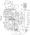
- Fig. 2 shows the schematic construction of the engine and automatic transmission system of a vehicle along with their associated components.
- the engine 10 is a four-cylinder engine in this embodiment. It is provided with an ignition device 11.
- the ignition device 11 has four ignition plugs 12 in correspondence with the number of cylinders of the engine 10.
- An intake pipe 16 for drawing air into the cylinders of the engine 10 is furnished with a throttle valve 17 by which the flow rate of the air to pass through the intake pipe 16 is regulated, a fuel injection device 13 which injects fuel, and an ISC (Idle Speed Control) valve 19 by which the flow rate of the air to be fed into the engine 10 during the idling of this engine is controlled.
- the throttle valve 17 is connected with an accelerator pedal 66 by a wire 67 in order that the valve opening thereof may change substantially linearly relative to the manipulated variable of the accelerator pedal 66.
- Attached to the accelerator pedal 66 is an accelerator opening sensor 78 which measures the opening ⁇ of this accelerator pedal.
- the fuel injection device 13 has four fuel injection valves 14 in correspondence with the number of cylinders of the engine 10.
- a radiator (not shown) for cooling the engine 10 is furnished with a water temperature sensor 71 which measures the temperature T w of cooling water contained in this radiator.
- An exhaust pipe 18 for emitting exhaust gas from the engine 10 into the open air is furnished with a catalyzer 65 and an air-fuel ratio sensor (or an O2 sensor) 72 for measuring an air-fuel ratio A/F (or an oxygen percentage O2).
- a flywheel 21 is mounted on the crankshaft 15 of the engine 10. Attached to the flywheel 21 is an engine r. p. m. sensor 73 which detects the revolution speed or r. p. m. of the crankshaft 15, in other words, that of the engine 10 (engine r. p. m. N e ).
- the flywheel 21 is directly connected with the pump 26 of a torque converter 25.
- the torque converter 25 is configured of the pump 26, a turbine 27 and a stator 28.
- the output shaft of the turbine 27, namely, that of the torque converter 25 is directly connected with a stepped automatic transmission mechanism 30.
- a turbine r. p. m. sensor 74 for measuring the revolution speed or r. p. m.
- the stepped automatic transmission mechanism 30 includes planetary gear mechanisms 31, 35, a band brake 40, and clutches 41, 42.
- the plurality of planetary gear mechanisms 31, 35 are disposed in correspondence with the number of gear shift stages. These planetary gear mechanisms 31, 35 are respectively configured of sun gears 32, 36 which are located centrally of the corresponding mechanisms; planetary gears 33, 37 which revolve round the corresponding sun gears 32, 36; and internal gears 34, 38 which are formed with teeth on the inner circumferential sides thereof and with which the corresponding planetary gears 33, 37 mesh.
- sun gears 32, 36 which are located centrally of the corresponding mechanisms
- planetary gears 33, 37 which revolve round the corresponding sun gears 32, 36
- internal gears 34, 38 which are formed with teeth on the inner circumferential sides thereof and with which the corresponding planetary gears 33, 37 mesh.
- the output shaft of the torque converter 25 is directly connected with the sun gear 32 of the rear planetary gear mechanism 31.
- the planetary gear 33 of the rear planetary gear mechanism 31 is directly connected with a propeller shaft 60, and the internal gear 38 of the front planetary gear mechanism 35.
- Both the internal gear 34 of the rear planetary gear mechanism 31 and the planetary gear 37 of the front planetary gear mechanism 35 have their rotations regulated by a forward one-way clutch 41.
- the planetary gear 37 of the front planetary gear mechanism 35 has its rotation regulated by a low one-way clutch 42.
- the band brake 40 can be applied to the rotary shaft of the sun gear 36 of the front planetary gear mechanism 35. Owing to the operations of the band brake 40, forward one-way clutch 41 and low one-way clutch 42, the rotations of the various gears are regulated to realize the first speed, second speed, reverse etc. of the vehicle.
- a vehicle speed sensor 75 is mounted on the output shaft of the stepped automatic transmission mechanism 30, namely, the propeller shaft 60 in order to measure the revolution speed or r. p. m. N o of this shaft (N o ⁇ V denoting the speed of the vehicle).
- the propeller shaft 60 is connected with rear wheels 63 through a differential 61 as well as a rear-wheel driving axle 62.
- the stepped automatic transmission mechanism 30 is equipped with a hydraulic control circuit 50 which actuates the band brake 40, forward one-way clutch 41 and low one-way clutch 42, and the actuation of which makes it possible to perform a transmission control, a lockup control, a line pressure control, an engine braking control, etc.
- the hydraulic control circuit 50 is provided with a hydraulic pump 51, and also elements for the aforementioned controls.
- the elements include a line pressure control valve 52 which adjusts the pressures of hydraulic lines, a lockup control valve 53 which serves to perform the lockup control, and transmission control valves 54 and 55 which change-over the plurality of hydraulic lines, thereby causing the band brake 40 etc. to switch the operations.
- the hydraulic control circuit 50 is provided with a line pressure sensor 76 for measuring the line pressure (denoted by symbol P oil ), and an oil temperature sensor 77 for measuring the temperature (denoted by symbol T oil ) of oil contained in the hydraulic line.
- the automatic transmission system 20 in this embodiment is constructed having the torque converter 25, the stepped automatic transmission mechanism 30 and the hydraulic control circuit 50 as explained above.
- the hydraulic control circuit 50 is controlled by a controller or control unit 100.
- the controller 100 is supplied with the cooling water temperature T w , air-fuel ratio A/F, engine r. p. m. N e , turbine (torque-converter output shaft) r. p. m. N t , transmission output shaft r. p. m. N o ( ⁇ the vehicle speed V), oil pressure P oil , oil temperature T oil and accelerator pedal opening ⁇ from the water temperature sensor 71, air-fuel ratio sensor 72, engine r. p. m. sensor 73, turbine r. p. m. sensor (torque-converter output shaft r. p. m.
- control unit 100 calculates the optimum gear shift position, line pressure, etc. on the basis of the supplied signals and delivers control signals to the actuators of the transmission control valves 54, 55, line pressure control valve 52, etc.
- a throttle valve opening sensor 79 is mounted for measuring the opening ⁇ of the electronic throttle valve 17a.
- the signal ⁇ from the sensor 79 is also input to the controller 100.
- the controller 100 is supplied with a signal S p from a mode switch 69 which changes-over an economy mode and a power mode.
- the mode switch 69 is mounted on or near a console panel so as to be readily manipulated by the driver of the vehicle.
- the economy mode is a mode in which the transmission system is upshifted while the vehicle speed V is low.
- the power mode is a mode in which the transmission system is upshifted after the vehicle speed V has become somewhat high.
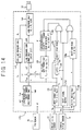
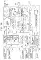
- the controller 100 includes an input torque calculation portion 131 in which torque converter characteristics are stored and which calculates the input torque (turbine torque) T t of the stepped transmission mechanism 30 from the engine r.p.m. N e and the turbine r.p.m.
- ratio calculation portion 136 which calculates the r.p.m. ratio e of the torque converter 25
- an r.p.m. ratio rate calculation portion 137 which calculates the rate of change de/dt of the r.p.m. ratio e of the torque converter 25
- a shift end recognition portion 138 by which a time somewhat earlier than an actual shift end time is recognized as a shift end from the rate of change de/dt of the r.p.m.
- an actual axle torque estimation portion 139 which calculates an axle torque (a torque acting on the driving axle 62) T o during the gear shift operation, from the change gear ratio g r during the gear shift operation, the gear ratio (final gear ratio) of the differential 61 and the input torque T t during the gear shift operation;
- a target axle torque calculation portion 140 which calculates a target axle torque T tar during the gear shift operation, in conformity with a function (to be indicated by Eq.
- a subtracter 141 which evaluates the deviation ⁇ T between the calculated actual axle torque T o and the target axle torque T tar ; a line pressure correction magnitude calculation portion 142 which calculates a correctional line pressure ⁇ PL from the torque deviation ⁇ T; a standard line pressure calculation portion 143 which calculates an ordinary line pressure PL from the input torque T t ; and a line-pressure calculation portion 144 which adds the ordinary line pressure PL and the correction magnitude ⁇ PL and then delivers the resulting sum to the solenoid of the line pressure control valve 52 as the line pressure PL.
- the above construction of the controller 100 is the functional construction of the controller 100, that is, the software architecture thereof.
- the controller 100 is constructed having a filter 101 and a waveshaping circuit 102 which receive signals from various sensors, a single-chip microcomputer 110, and a driving circuit 103 which delivers drive control signals to various actuators such as valves.
- the microcomputer 110 includes a CPU (Central Processing Unit) 111 which executes various calculations, a ROM (Read-Only Memory) 112 in which programs etc. for the processing of the CPU 111 are stored, a RAM (Random Access Memory) 113 in which various data etc.
- CPU Central Processing Unit
- ROM Read-Only Memory
- RAM Random Access Memory
- the various functions of the controller 100 are fulfilled in such a way that the CPU 111 executes the predetermined calculations by the use of the programs, data etc. which are stored in the ROM 112 and the RAM 113.
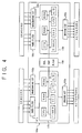
- a controller 100a may well include a single-chip microcomputer 110x for controlling the speed change gear and a single-chip microcomputer 110y for controlling the engine.
- the controller 100a should preferably include two filters 101x and 101y, waveshaping circuits 102x and 102y, driving circuits 103x and 103y, etc. for the speed change gear control and for the engine control, respectively.
- the speed change gear controlling microcomputer 110x and the engine controlling microcomputer 110y are interconnected through a dual port RAM 104.
- a controller 100b may well be configured of two units 120x and 120y which are completely independent of each other for the engine control and for the speed change gear control.
- the respective units 120x and 120y include hard filters 101x and 101y, waveshaping filters 102x and 102y, driving circuits 103x and 103y, single-chip microcomputers 110x and 110y, and communication circuits 105x and 105y.
- shift signal output means is constructed of the shift signal output portion 132.
- shift start recognitive parameter grasp means is constructed having the engine r.p.m. sensor 73, turbine r.p.m. sensor 74 and input torque calculation portion 131
- shift end recognitive parameter grasp means is constructed having the engine r.p.m. sensor 73, turbine r.p.m. sensor 74, r.p.m. ratio calculation portion 136 and r.p.m. ratio rate calculation portion 137.
- shift start recognition means is constructed having the shift start recognition portion 134 and an AND circuit which takes the AND between the output from the shift start recognition portion 134 and the shift signal sol from the shift signal output portion 132
- shift end recognition means is constructed having the shift end recognition portion 138 and an AND circuit which takes the AND between the output from the shift end recognition portion 138 and the shift signal sol from the shift signal output portion 132.
- undergoing shift manipulated variable calculation means is constructed having the line pressure correction magnitude calculation portion 142, standard line pressure calculation portion 143 and command line pressure calculation portion 144.
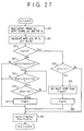
- the corresponding portions of the controller 100 read the shift signal sol , engine r.p.m. N e , torque-converter output shaft (turbine) r.p.m. N t and throttle valve opening ⁇ .
- the steps S31 and S32 are executed by the input torque calculation portion 131.
- the step S33 is followed by a step S37.
- step S34 is followed by a step S42.
- step S34 is followed by a step S35.
- the controller 100 decides if the current shift signal sol (n) is greater than the last shift signal sol (n-1). In a case where the current shift signal sol (n) is greater, the upshift is decided, and the routine proceeds to a step S36.
- the current input torque T t is stored as the signal T sh (in the latch 133).
- the shift start recognition portion 134 decides whether or not the input torque T t calculated anew is greater than an upshift start level (T sh + k1) which is obtained by adding a predetermined value k1 to the latched input torque T sh .
- an upshift start flag FlgA is set to "1" at a step S38.
- the routine proceeds to a step S39, at which the flag FlgD before the upshift start is set to "1".
- the routine proceeds to a step S40, at which the shift start recognition portion 134 decides whether or not the current shift signal sol (n) is smaller than the last shift signal sol (n-1). On condition that the current shift signal sol (n) is smaller, the downshift is decided, and the routine proceeds to a step S41.
- the current input torque T t is stored as the signal T sh (in the latch 133).
- the shift start recognition portion 134 decides whether or not the input torque T t calculated anew is greater than a downshift start level (T sh + k2) which is obtained by adding a predetermined value k2 to the latched input torque T sh .
- a downshift start flag FlgB is set to "1" at a step S43.
- the routine proceeds to a step S44, at which the flag FlgC before the downshift start is set to "1".
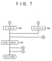
- Fig. 7 The subsequent flow of the routine is shown in Fig. 7.
- the flag FlgD before the upshift start is set to "0" at a step S45, which is followed by a step S47.
- the flag FlgC before the downshift start is set to "0" at a step S46, which is also followed by the step S47.
- the last shift signal sol( n-1) is set to the current shift signal sol (n). Thereafter, the routine returns.
- the routine proceeds to a step S58.
- the shift end recognition portion 138 decides if the rate of change
- is smaller, it is decided that the transmission mechanism 30 is still undergoing the gear shift, and the routine proceeds to a step S59.
- the target axle torque calculation portion 140 calculates the undergoing shift target axle torque T tar in conformity with (Eq.
- T tar k 3 ⁇ g r ( sol ) ⁇ g e ⁇ T sh
- symbol k3 denotes a constant
- symbol g r ( sol ) denotes a function which is determined depending upon the change gear ratio given by the shift signal sol
- symbol g e denotes the gear ratio of the differential 61.
- the standard line pressure calculation portion 143 calculates the line pressure PL in conformity with a function f(T sh ) of the input torque T sh stored at the change of the shift signal sol .
- the routine proceeds to a step S65.
- the shift end recognition portion 138 decides whether or not the rate of change
- is smaller, it is decided that the transmission mechanism 30 is still undergoing the gear shift, and the routine proceeds to the step S59 stated before.
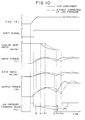
- the input torque (turbine torque) T t is proportional to the square N e 2 of the engine r.p.m. N e as indicated by (Eq. 1), and the variation thereof at the time of the shift start enlarges. Therefore, the time of the shift start can be recognized early and reliably by recognizing the mechanical shift start on the basis of the change of the input torque T t as in this embodiment (the shift start is recognized at a point of time t2).
- the undergoing shift line pressure correction is concretely made so that the line pressure under the gear shift may lower.
- the input torque T t diminishes, and the variation of the output torque T o decreases, so that the shift shock is relieved.
- the line pressure is corrected so as to lower in this embodiment, the magnitude of slip in the stepped automatic transmission mechanism 30 enlarges. Accordingly, the point of time t3 at which the end of the gear shift is recognized and the point of time t4 at which the gear shift is actually completed become later than in the prior art.
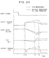
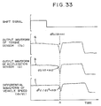
- the downshift operation is performed in the process in which the accelerator pedal 66 is depressed in to abruptly enlarge the throttle valve opening ⁇ .
- the shift signal sol changes after the lapse of a certain time period from when the throttle valve opening ⁇ begins to enlarge.
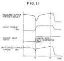
- the input torque T t increases with the enlargement of the throttle valve opening ⁇ , and it exhibits first peak value in the vicinity of an actual shift start time t1. Thereafter, it decreases till an actual shift end time t4. After the actual shift end time t4, the input torque T t increases and overshoots until it becomes stable.
- the output torque T o changes similarly to the input torque T t .
- the output torque T o changes more abruptly than the input torque T t due to the torque amplifying action of the stepped automatic transmission mechanism 30.
- the shift start time t2 of the downshift operation is recognized in accordance with the change of the input torque T t as in this embodiment, it is recognized earlier than the actual shift start time t1 unlike that of the upshift operation.
- Such recognition of the shift start time t2 earlier than the actual shift start time t1 is effective in the case of controlling the output torque T o , on the ground that the output torque T o begins to increase before the actual shift start time t1.
- the line pressure correction is performed. This line pressure correction is made so that the line pressure may lower. In the case of the downshift, the lowering of the line pressure quickens the operation of engaging or disengaging the clutch of the stepped transmission mechanism 30.
- the actual shift start time t1 and the actual shift end time t4 become earlier than respectively corresponding times (t1) and (t4) in the absence of the line pressure correction, and the time period of the downshift shortens. Moreover, the depression of the output torque T o at the shift end time t4 is smaller compared with that at the shift end time (t4), so that the shift shock is reduced, though slightly.
- the undergoing shift change gear ratio g r may well be approximated so as to abruptly rise along a mere straight line of fixed gradient from a change gear ratio level before the gear shift, up to a change gear ratio level after the gear shift, at the same time as the recognition of the shift start time t2.
- it may well be approximated so as to rise in steps.
- Certain types of automatic transmission systems are furnished with an economy mode in which the upshift is effected while the vehicle speed is low, and a power mode in which the upshift is effected when the vehicle speed has risen to some extent, in spite of an identical throttle valve opening.
- This modification is directed toward an automatic transmission system which is furnished with such economy and power modes. It consists in altering the processing content of the step S50 in Fig. 8 illustrative of the control operation flow of the first embodiment, and in adding a step S59a. The other steps are the same as in the first embodiment, and shall be omitted from the description.
- a mode selection flag FlgM is read along with the shift signal sol , the engine r.p.m. N e , etc.
- either of the economy and power modes is selected by the driver of the vehicle manipulating the mode switch 69 (shown in Fig. 2).
- the controller 100 executes the steps S51, S52, ..., and S65 or S58.
- the line pressure correction control is performed in only the case of the economy mode where there is greater shift shock, it may well be performed also in the case of the power mode.
- the correctional line pressure ⁇ PL is evaluated from the difference ⁇ T between the target axle torque T tar and the actual axle torque T o in this modification and the first embodiment, it may well be evaluated from the throttle valve opening ⁇ , engine r.p.m. N e and vehicle speed V in conformity with a function f1( ⁇ , N e , V).
- the first embodiment recognizes the end of the gear shift when the rate of change
- a controller 100c shown in Fig. 14 that recognizes the shift end when the r.p.m. ratio e has become less than or equal to the predetermined value (k6). Since the controller 100c does not recognize the shift end from the rate of change
- N t measured by the turbine r.p.m. sensor 74, and it delivers the calculated value e_directly to a shift end recognition portion 138a.
- the shift end recognition portion 138a recognizes that the gear shift has ended, and it delivers a recognition signal to the AND circuit.
- a controller 100d shown in Fig. 15 recognizes the shift end from the change gear ratio r of the stepped automatic transmission mechanism 30.
- the change gear ratio r thus obtained is delivered to a shift end recognition portion 138b.
- the shift end recognition portion 138b recognizes that the gear shift has ended, and it delivers a recognition signal to the AND circuit.
- the value k7 which is slightly smaller than the change gear ratio after the gear shift as indicated by the shift signal sol is employed as a threshold value for the recognition of the shift end, such threshold values are required for the respective change gear ratios after the ends of the gear shifts.
- values for the upshifts and values for the downshifts are prepared as the threshold values.
- This embodiment consists in that the line pressure correction control in the first embodiment is performed by a different method.
- the recognition of the shift start as well as the shift end, the estimation of the actual axle torque, etc. in this embodiment are the same as in the first embodiment.
- a controller 100i in this embodiment includes an input torque latch portion 170 in which an input torque T t calculated by an input torque calculation portion 131 is temporarily held, a reference line pressure setting portion 171 which sets a reference line pressure PL o by the use of a line pressure setting torque T s being the input torque T t held by the latch portion 170, a reference line pressure compensation portion 172 which alters the reference line pressure PL o between during a gear shift operation and in a predetermined time period after the end of the gear shift operation in order to establish unequal line pressures during the gear shift operation and in the predetermined time period after the shift end, a compensative gain output portion 173 which delivers a gain k3 for use in altering the reference line pressure PL o in the reference line pressure compensation portion 172, a learning reference torque latch portion 174 which holds therein an actual axle torque T o at the point of time when a shift signal change decision flag FlgE has become "1”, a learning torque latch portion 175 which holds therein an
- the function learning correction portion 178 contains a reference line pressure setting map.
- the reference line pressure functions j(T s ) of the respective sorts of gear shifts are depicted on the map with the axis of abscissas representing the line pressure setting torque T s and the axis of ordinates representing the reference line pressures PL o .
- the other blocks and signals of the controller 100i are the same as in the controller 100 shown in Fig. 1.
- step S163 the read input torque T t is set as the line pressure setting torque T s , and the shift signal change decision flag FlgE is set to "0".
- step S164 the current shift signal sol (n) is set as the last shift signal sol (n-1). Thereafter, the routine returns.
- step S165 the shift signal change decision flag FlgE is set to "1" and which is followed by the step S166.
- the input torque T t is subjected to filtering. The filtering is performed from the time of the change of the shift signal sol and for a time period in which the mechanical gear shift of the stepped automatic transmission mechanism 30 is not actually started, for example, for about 200 [msec].
- the routine proceeds to a step S168, at which the read input torque T t is set as the line pressure setting torque T s and which is followed by the step S164.
- the routine proceeds to a step S170.
- the input torque FT t filtered at the step S166 is set as the line pressure setting torque T s , whereupon the routine proceeds to a step S171.
- step S172 at which the line pressure setting torque T s in the last cycle is set as the line pressure setting torque T s in the current cycle once more (the last torque T s is held) and which is followed by the step S164.
- step S171 that is, where the end of the mechanical gear shift has been recognized
- steps S163 and S164 are executed, and the routine returns.
- the corresponding portions of the controller 100i read the line pressure setting torque T s and the shift signal sol set in the flow of Fig. 17, at a step S173.
- the flow of Fig. 18 illustrates the line pressure control operation for a time period from a shift start recognition time t2 to a shift end recognition time t3 (refer to Fig. 19), and it is executed by the reference line pressure setting portion 171.
- the shift signal sol indicates the 1 st -2 nd speed change is decided at a step S174, and whether the shift signal sol indicates the 2 nd -3 rd speed change or 3 rd -4 th speed change is decided at a step S175.
- the function No. 2 among the plurality of line pressure setting functions j(T s ) prepared beforehand is employed; when the shift signal sol indicates the 2 nd -3 rd speed change, the line pressure setting function No. 3 is employed; and when the shift signal sol indicates the 3 rd -4 th speed change, the line pressure setting function No. 4 is employed (steps S176, S177 and S178).
- the line pressure setting function j(T s ) selected at any of the steps S176, S177 and S178 is extracted from within the reference line pressure setting map stored in the function learning correction portion 178, and the line pressure setting torque T s is substituted into the selected function j(T s ) so as to derive the line pressure PL which is to be applied for the time period from the shift start recognition time t2 to the shift end recognition time t3.
- the derived line pressure PL is delivered to the solenoid of the line pressure control valve 52.
- the line pressure command value PL decreases for the time period from the shift start recognition time t2 to the shift end recognition time t3 as shown in Fig. 19.
- the variation of the output torque T o diminishes in the meantime, and the shock of the vehicle attributed to the gear shift is reduced.
- the illustration of Fig. 19 corresponds to the upshift operation.
- the line pressure control is performed only for the time period from the shift start recognition time t2 to the shift end recognition time t3 as in the first embodiment, the output torque T o decreases abruptly after the shift end recognition time t3 as shown in Fig. 9, and the shift shock arises at this point.
- the line pressure is further lowered for a fixed time period from the shift end recognition time t3 as shown in Fig. 19, whereby the abrupt depression of the output torque T o which arises after the shift end recognition time t3 is prevented, to thus reduce the shift shock.
- the line pressure PL for the fixed time period from the shift end recognition time t3 is evaluated by the line pressure compensation portion 172.
- the line pressure compensation portion 172 multiplies the reference line pressure PL o evaluated by the reference line pressure setting portion 171, by 0.8 as the compensative gain k3 during the gear shift operation (the predetermined time period from the shift start recognition time t2 to the shift end recognition time t3) and by 1 (one) as the compensative gain k3 for the fixed time period from the shift end recognition time t3.
- the line pressure compensation portion 172 supplies the solenoid of the line pressure control valve 52 with the product between the reference line pressure PL o and the compensative gain k3.
- This embodiment does not perform the so-called feedback control in which the torque of the driving axle (62 in Fig. 2) is controlled with the estimated actual axle torque T o as in the first embodiment, but it performs the feedforward control in which the axle torque is controlled with any of the functions j(T s ) prepared beforehand for the respective gear shift positions.
- the feedforward control it is difficult to cope with the discrepancies and secular changes of the transmission mechanisms 30 and torque converters 25 of the individual vehicles.
- This embodiment therefore performs an undergoing shift line pressure learning control in order to cope with such discrepancies and secular changes.
- Fig. 20 is a flow chart of the undergoing shift line pressure learning control in this embodiment.
- a flag FlgF for indicating that the shift signal change decision flag FlgE has become "1" is "1" is decided at a step S182.
- the routine proceeds to a step S183 when the flag FlgF is not "1", and to a step S187 when the flag FlgF is "1".
- step S183 whether or not the shift signal change decision flag FlgE is "1" is decided.
- the routine proceeds to a step S184.
- the routine returns as indicated by symbol A.
- the routine proceeds to a step S185.
- the learning reference torque latch portion 174 latches as the learning reference output torque T os the estimated output torque T o at the time when the shift signal change decision flag FlgE has been decided as "1".
- the flag FlgF is set to "1" at a step S186, which is followed by the step S187.
- step S187 whether or not the shift start flag Flgs is "1" is decided.
- the routine returns.
- the routine proceeds to a step S188, at which whether or not the learning timing decision flag FlgG is "1" is decided.
- the routine returns in a case where the flag FlgG is "1”, and it proceeds to a step S189 in a case where the flag FlgG is not "1", that is, where the time is not the timing for sampling the learning output torque.
- a time period of, for example, 100 [msec] has lapsed since the mechanical shift start recognition time t2 is decided at the step S189.
- the learning torque latch portion 175 latches the estimated output torque T o on this occasion as the learning torque T oe at a step S190.
- the learning timing decision flag FlgG is set to "1" at a step S191, which is followed by a step S192.
- the learning-correctional line pressure deviation calculation portion 176 calculates the deviation ⁇ T se between the learning reference output torque T os obtained at the step S185 and the learning torque T oe obtained at the step S190.
- the character of the deviation ⁇ T se will be briefly explained. Since the learning reference output torque T os is the output torque T o at the change of the shift signal sol , it is the output torque T o in a torque phase (an interval extending from the change of the shift signal sol to the point of time t1 at which the mechanical gear shift is actually started) as shown in Fig. 19.
- the learning torque T oe is the output torque T o 100 [msec] after the shift start recognition time t2, it is the output torque T o after a torque depression observed at the initial stage of an inertia phase (an interval extending from the actual mechanical shift start time t1 to the point of time t4 at which the gear shift is actually ended, and an inertial force is acting on the driving axle 62 during the interval). That is, the learning reference output torque T os and the learning torque T oe are the output torques T o before and after the torque depression observed at the initial stage of the inertia phase, respectively. It is preferable from the viewpoint of shift shock reduction that the deviation ⁇ T se between the output torques T o before and after the torque depression is basically 0 (zero).
- the line pressure deviation calculation portion 177 calculates the line pressure deviation ⁇ PL in conformity with a function f whose parameters are the aforementioned deviation ⁇ T se and the line pressure setting torque T s at the step S170 in Fig. 17.
- various controlled variables are set so that the line pressure deviation ⁇ PL may become 0 (zero) at the shipment of the vehicle.
- the line pressure deviation ⁇ PL is added to the reference line pressure PL o delivered at the step S180 in Fig. 18, and the resulting sum is plotted on the reference line pressure function map as shown in Fig. 21.
- "1" is added to the number of times n of plotting.
- Whether or not the number of times n of plotting has reached a predetermined number of times a is decided at a step S196.
- the routine proceeds to a step S197 when it has the number of times a has been reached, and it returns when not.
- the number of times n of the plotting is reset to 0 (zero).
- the corresponding one of the reference line pressure functions j(T s ) is corrected on the basis of the plurality of reference line pressures PL o plotted on the reference line pressure function map. Concretely, in a case shown in Fig.
- the steps S194 ⁇ S198 are executed by the function learning correction portion 178.
- the undergoing shift line pressure learning correction control stated above may well be performed continually, it is performed upon elapsing of a predetermined term (for example, every half year) or every predetermined traveling distance (for example, every 5000 [km]) in this embodiment.
- the reference line pressure functions j(T s ) are subjected to the learning corrections every predetermined time period or every predetermined traveling distance, so that the shift shocks can be prevented from becoming worse due to the secular changes.
- a controller 100e in this embodiment consists in that, in order to reduce the shock of a vehicle attributed to a gear shift operation, an engine torque T e during the gear shift operation is corrected in accordance with the deviation ⁇ T between an estimated axle torque T o and a target axle torque T tar during the gear shift operation.
- the functions of grasping a shift start time and a shift end time, etc. are the same as in the controller 100 of the first embodiment. Accordingly, the engine torque correction in the gear shift operation will be chiefly explained below.
- the same functional portions (131, ..., 139 and 141) as in the controller 100 of the first embodiment shall have identical numerals assigned thereto and shall not be repeatedly explained.
- This embodiment controls the throttle valve opening ⁇ in order to control the engine torque T e . Unlike the first embodiment, therefore, this embodiment is applicable only to the automatic transmission system furnished with the electronic throttle valve 17a (shown in Fig. 2).
- the controller 100e of this embodiment includes a target axle torque calculation portion 140a which calculates the target axle torque T tar from the measured vehicle speed V and accelerator pedal opening ⁇ by the use of the target axle torque map prepared beforehand, an engine torque calculation portion 150 which calculates an engine torque deviation ⁇ T e ' from the axle torque deviation ⁇ T between the target axle torque T tar and the calculated actual axle torque T o and which also calculates a target engine torque T e ⁇ tar corresponding to the target axle torque T tar , a correctional engine torque calculation portion 156 which calculates the sum T e between the engine torque deviation ⁇ T e ' and target engine torque T e ⁇ tar calculated by the engine torque calculation portion 150, and a throttle valve opening calculation portion 157 which derives from an engine output characteristics map the throttle valve opening ⁇ that affords the engine torque T e calculated by the correctional engine torque calculation portion 156.
- the engine torque calculation portion 150 includes a turbine torque calculator 151 by which the target axle torque T tar and the axle torque deviation ⁇ T are respectively converted in terms of a target turbine torque T t ⁇ tar and a turbine torque deviation ⁇ T t , a pump torque calculator 152 by which the target turbine torque T t ⁇ tar and turbine torque deviation ⁇ T t are respectively converted in terms of a target pump torque T p ⁇ tar and a pump torque deviation ⁇ T p , an engine torque calculator 153 by which the target pump torque T p ⁇ tar and pump torque deviation ⁇ T p are respectively converted in terms of the target engine torque T e ⁇ tar and an engine torque deviation ⁇ T e , a PID (proportional-plus-integral-plus-derivative)-control engine torque deviation calculator 154 by which the engine torque deviation ⁇ T e calculated by the engine torque calculator 153 is converted in terms of the PID-control engine torque deviation ⁇ T e ', and a gain calculator 155 which calculates gains
- the target axle torque calculation portion 140a derives the target axle torque T tar corresponding to the vehicle speed V and accelerator pedal opening ⁇ measured by the respective sensors 75 and 78, with reference to the target axle torque map.
- the derived target axle torque T tar is delivered to the turbine torque calculator 151 of the engine torque calculation portion 150.
- the turbine torque calculator 151 calculates the target turbine torque T t ⁇ tar in such a way that the target axle torque T tar is divided by the gear ratio g e of the differential 61 shown in Fig. 2 and the change gear ratio indicated by the current shift signal sol .
- the torque ratio ⁇ of the torque converter 25 is derived from torque converter characteristics prepared beforehand, and the target turbine torque T t ⁇ tar is divided by the derived torque ratio ⁇ , thereby calculating the target pump torque T p ⁇ tar .
- an inertial torque I e ⁇ dN e /dt is added to the target pump torque T p ⁇ tar , thereby calculating the target engine torque T e ⁇ tar .
- the engine torque T e and the pump torque T p are basically equal.
- the target engine torque T e ⁇ tar calculated above is delivered to the correctional engine torque calculation portion 156.
- the engine torque deviation ⁇ T e ' is not delivered from the PID-control engine torque deviation calculator 154 to the correctional engine torque calculation portion 156.
- the engine torque deviation ⁇ T e ' is not added to the target engine torque T e ⁇ tar , but this target engine torque T e ⁇ tar left intact is delivered to the throttle valve opening calculation portion 157.
- the throttle valve opening calculation portion 157 calculates the throttle valve opening ⁇ from the engine torque T e and the engine r.p.m. N e measured by the engine r.p.m. sensor 73, with reference to the engine output characteristics map, and it delivers the calculated value to the actuator of the electronic throttle valve 17a.
- the opening of the throttle valve 17a is controlled so as to normally produce the target axle torque T tar corresponding to the accelerator pedal opening ⁇ and the vehicle speed v, unlike the first embodiment in the case where the throttle valve 17 and the accelerator pedal 66 are mechanically linked.
- the inputs of the engine r.p.m. etc. to the functional blocks are omitted from Fig. 23 for the brevity of illustration.
- the shift signal sol is input to the turbine torque calculator 151, and the engine r.p.m. N e and the turbine r.p.m. N t are input to the pump torque calculator 152 in order to find the torque ratio ⁇ .
- the engine r.p.m. N e from the engine r.p.m. sensor 73 is input to the engine torque calculator 153, the gain calculator 155 and the throttle valve opening calculation portion 157.
- the actual axle torque T o during the time period from the shift start time grasped by the shift start recognition portion 134 to the shift end time grasped by the shift end recognition portion 138 is calculated by the actual axle torque estimation portion 139 in the same manner as in the first embodiment.
- the target axle torque T tar is evaluated by the target axle torque calculation portion 140a in the same manner as in the ordinary running.
- the deviation ⁇ T between the target axle torque T tar and the calculated actual axle torque T o is evaluated by the subtracter 141.
- the turbine torque calculator 151 of the engine torque calculation portion 150 is supplied with the target axle torque T tar and the axle torque deviation ⁇ T.
- the target turbine torque T t ⁇ tar corresponding to the target axle torque T tar , and the turbine torque deviation ⁇ T t corresponding to the axle torque deviation ⁇ T are calculated in the same manner as in the ordinary running. Further, in the same manner as in the ordinary running, the pump torque calculator 152 calculates the target pump torque T p ⁇ tar corresponding to the target turbine torque T t ⁇ tar , and the pump torque deviation ⁇ T p corresponding to the turbine torque deviation ⁇ T t , while the engine torque calculator 153 calculates the target engine torque T e ⁇ tar corresponding to the target pump torque T p ⁇ tar , and the engine torque deviation ⁇ T e corresponding to the pump torque deviation ⁇ T p .
- the engine torque deviation ⁇ T e calculated by the engine torque calculator 153 is converted into the PID-control engine torque deviation ⁇ T e '.
- the gains for use in the conversion are derived by the gain calculator 155 in correspondence with the engine r.p.m. N e measured by the engine r.p.m. sensor 73.
- the target engine torque T e ⁇ tar calculated by the engine torque calculator 153, and the engine torque deviation ⁇ T e ' calculated by the PID-control engine torque deviation calculator 154 are both supplied to the correctional engine torque calculation portion 156.
- the throttle valve opening calculation portion 157 calculates the throttle valve opening ⁇ corresponding to the engine torque T e delivered from the correctional engine torque calculation portion 156 and then delivers the calculated throttle valve opening ⁇ to the actuator of the electronic throttle valve 17a.
- the shift start is recognized on the basis of the change of the input torque (turbine torque) (the point of time at which the shift start is recognized is t2) in the same manner as in the first embodiment. It is therefore possible to recognize the shift start time early and reliably.
- the actual axle torque (output torque) T o increases relative to the target axle torque T tar , and hence, the correction of decreasing the throttle valve opening ⁇ is made so as to reduce the deviation T of both the torques.
- the input torque T t does not increase, with the result that the undergoing shift axle torque does not increase.
- the shift shock can be relieved.
- the upshift increases the change gear ratio, with the result that the axle torque becomes smaller after the gear shift than before the gear shift.
- the change of the axle torque on this occasion appears as the shift shock. It is accordingly preferable to reduce the difference between the axle torque before the gear shift and the axle torque after the gear shift as much as possible.
- the target axle torque T tar is set in accordance with the vehicle speed V and the accelerator pedal opening ⁇ , irrespective of whether or not the gear shift is progressing. Consequently, when the vehicle speed V and the accelerator pedal opening ⁇ are constant, the target axle torque T tar before the gear shift remains unchanged even after the end of the gear shift.
- the throttle valve opening ⁇ is enlarged after the shift end in order to restrain the actual axle torque T o from becoming lower than the same target axle torque T tar as before the gear shift.
- the engine torque increases to prevent the axle torque T o from decreasing.
- the throttle valve opening ⁇ does not begin to enlarge at this point of time. Therefore, the throttle valve opening ⁇ should preferably be enlarged after the upshift end recognition time t3 as shown in Fig. 24, in anticipation of the fact that the actual axle torque T o becomes smaller than the target axle torque T tar after the actual shift end.
- the throttle valve opening is controlled in order to control the engine output
- the quantity of fuel injection may well be controlled by a similar technique.
- an engine whose output is manipulated by controlling the quantity of fuel injection for example, a diesel engine
- a fuel injection quantity correction control ought to be performed instead of the throttle valve opening correction control.
- lean mixture combustion engines have been developed in order to reduce fuel costs.
- combustions are performed at air-fuel ratios of, for example, 18.0 and 24.0 other than the theoretical air-fuel ratio of 14.7.
- This modification consists in adapting the controller 100e of the third embodiment to such a lean mixture combustion engine.
- a controller 100f in this modification replaces the throttle valve opening calculation portion 157 in the third embodiment with a throttle valve opening calculation portion 157a which calculates the throttle valve opening ⁇ in accordance with the engine r.p.m. N e , engine torque T e and air-fuel ratio A/F, and an air-fuel ratio setting portion 158 which sets the air-fuel ratio A/F for use in calculating the throttle valve opening ⁇ .
- the other functional construction of the controller 100f of this modification is the same as that of the controller 100e of the third embodiment.
- the air-fuel ratio setting portion 158 is furnished with an air-fuel ratio map which is used for setting the air-fuel ratio A/F (14.7, 18 or 24) with the target engine torque T e ⁇ tar and the engine r.p.m.
- the air-fuel ratio setting portion 158 sets the air-fuel ratio A/F which corresponds to the target engine torque T e ⁇ tar delivered from the engine torque calculation portion 150 and the engine r.p.m. N e measured by the engine r.p.m. sensor 73.
- the throttle valve opening calculation portion 157a is furnished with an engine characteristics map which is used for calculating the throttle valve opening ⁇ with the engine r.p.m. N e , the engine torque T e and the air-fuel ratio A/F as parameters.
- the throttle valve opening calculation portion 157a calculates the throttle valve opening ⁇ which corresponds to the engine r.p.m.
- the calculated value ⁇ is delivered to the actuator of the electronic throttle valve 17a.
- the engine torque T e can be controlled to reduce the shift shock even in the lean mixture combustion engine.
- This modification consists in coping with the shift shock in such a way that the engine torque T e of the lean mixture combustion engine is controlled by making the ignition timings of the ignition plugs (12 in Fig. 2) different for the respective air-fuel ratios A/F.
- a controller 100g in this modification includes an ignition timing setting portion 159 which sets the ignition timings adv in accordance with the target engine torque T e ⁇ tar and engine torque deviation ⁇ T e ' calculated by the engine torque calculation portion 150, and an air-fuel ratio setting portion 158 which sets the air-fuel ratio A/F in accordance with the engine r.p.m. N e measured by the engine r.p.m. sensor 73 and the target engine torque T e ⁇ tar calculated by the engine torque calculation portion 150.
- the air-fuel ratio setting portion 158 contains the air-fuel ratio map and uses it for setting the air-fuel ratio A/F which corresponds to the engine r.p.m. N e measured by the engine r.p.m.
- the ignition timing setting portion 159 contains the ignition timing maps of the respective air-fuel ratios A/F (14.7, 18 and 24) for setting the ignition timings adv with the engine torque deviation ⁇ T e ', target engine torque T e ⁇ tar and engine r.p.m. N e as parameters.
- the ignition timing setting portion 159 selects one of the plurality of ignition timing maps in accordance with the air-fuel ratio A/F set by the air-fuel ratio setting portion 158, and refers to the selected map to determine the ignition timings adv which correspond to the engine r.p.m. N e measured by the engine r.p.m.
- a signal indicative of the ignition timings adv is delivered from the ignition timing setting portion 159 to the distributor 11b of the ignition device 11 through the igniter 11a thereof, whereby the ignition timings adv of the ignition plugs 12 are controlled.
- this modification controls the ignition timings of the ignition plugs 12 unlike the preceding modification or the third embodiment, it is applicable even to the automatic transmission system which is not equipped with the electronic throttle valve.
- the controls of the axle torque under the gear shift operations intended to relieve the shift shocks can be performed by changing the oil line pressure of the automatic transmission system, the opening of the throttle valve and the ignition timings of the ignition plugs. Needless to say, the control can also be performed by changing the quantity of fuel injection.
- the mechanical shift start can be grasped comparatively early by sensing the abrupt fall or depression of the actual axle torque T actual (the shift start is recognized at the point of time t2 in this embodiment).
- a torque sensor is mounted on the driving axle 62 (in Fig. 2), and the mechanical shift start is grasped in accordance with the change of the torque value measured by the torque sensor.
- Fig. 27 is a flow chart of shift start grasp processing in the upshift operation.
- step S73 if the current shift signal sol (n) is greater than the last shift signal sol (n-1) is decided. In a case where the current shift signal sol (n) is not greater than the last shift signal sol (n-1), no gear shift is performed. At a step S74, therefore, the last shift signal sol (n-1) is set as the current shift signal sol (n), and the last throttle valve opening ⁇ (n-1) is set as the current throttle valve opening ⁇ (n). In a case where the current shift signal sol (n) has been decided greater than the last shift signal sol (n-1) at the step S73, the routine proceeds to a step S75.
- the upshift is performed when the throttle valve opening has abruptly enlarged to some extent. For this reason, the step S75 is executed in order to exclude an occasion where the throttle valve opening is merely changed to change the output torque without the performance of the upshift.
- the current throttle valve opening ⁇ (n) does not exceed the value obtained by subtracting the specified constant k1 from the last throttle valve opening ⁇ (n-1), it is decided that the operation of the automatic transmission system is not in the inertia phase of the gear shift.
- the routine proceeds to the step S74 stated before.
- the routine proceeds to a step S76, at which if the rate of change ⁇ T o of the output torque T o is smaller than a constant -k2 (which varies depending upon the stage of the gear shift to be performed) is determined.
- a constant -k2 which varies depending upon the stage of the gear shift to be performed
- the state of the automatic transmission system is decided as being at the start of the inertia phase, and the routine proceeds to a step S77.
- the inertia phase start decision flag FlgI is set to "1" at the step S77, which is followed by the step S74. Thereafter, the routine returns.
- FlgI 1 holds at the step S72, whether or not the rate of change ⁇ T o of the output torque T o has become greater than 0 (zero) is determined at a step S78.
- the torque sensor is mounted on the driving axle 62 so as to directly detect the axle torque
- this measure is not restrictive.
- the torque of the driving axle 62 may well be obtained in such a way that a torque sensor is mounted on the propeller shaft 60 so as to detect the torque of this shaft 60, and that the detected torque is multiplied by the gear ratio of the differential 61.
- An alternative expedient is such that, as in the first embodiment, the input torque T t of the stepped automatic transmission mechanism 30 is calculated from the engine r.p.m. N e and the turbine r.p.m. N t without employing any torque sensor, while the change gear ratio g r during the gear shift operation is estimated on the basis of the r.p.m.
- the axle torque is calculated from the change gear ratio g r and the input torque T t .
- the axle torque is calculated from the two estimated values of the estimated value of the input torque and that of the undergoing shift change gear ratio, and it is difficult to precisely grasp the change of the axle torque. Accordingly, in the case of grasping the shift start on the basis of the axle torque, it is preferable to use the axle torque measured by the torque sensor.
- Fig. 29 is a flow chart of shift start recognition processing in the upshift operation.
- the last shift signal sol (n-1) is set as the current shift signal sol (n), whereupon the routine returns.
- the gear shift is decided, and the routine proceeds to a step S87.
- the rate of change ⁇ N t of the turbine r.p.m. N t is set as T r .
- step S88 whether or not the rate of change ⁇ N t in the current cycle is smaller than a value obtained by subtracting a specified constant k3 (which varies depending upon the r.p.m. N t at the shift start) from the magnitude T r (the rate of change ⁇ N t of the turbine r.p.m. N t in the last cycle) is determined.
- a specified constant k3 which varies depending upon the r.p.m. N t at the shift start
- T r the rate of change ⁇ N t of the turbine r.p.m. N t in the last cycle
- step S86 is executed, and the routine returns.
- the routine proceeds to a step S89, at which the shift signal change decision flag FlgE is set to "1". Thereafter, the step S86 is executed, and the routine returns.
- the shift start can be recognized (at the point of time t2) earlier than the shift start recognition time A in the prior art.
- the shift start can be recognized earlier than the shift start recognition time A in the prior art, in the same manner as in this embodiment.
- this embodiment pertains to the recognition of the mechanical shift start.
- Fig. 33 shows waveforms which correspond to the output torque in the gear shift operation.
- Letter a indicates the output waveform of a torque sensor
- letter b indicates the output waveform of an acceleration sensor
- letter c indicates the differential waveform of the speed of a vehicle.
- the acceleration of the vehicle and the differentiation of the vehicle speed are basically the same, and they are in proportional relationships with the torque of the driving axle. Accordingly, the mechanical shift start can be recognized from the change of the acceleration of the vehicle or the differentiation of the vehicle speed, in the same manner as in the fourth embodiment in which the mechanical shift start is recognized from the change of the axle torque.
- the shift start can be detected at each of points denoted by dT o /dt ⁇ m1 , dG/dt ⁇ m2 and d 2 V/dt 2 ⁇ m3 .
- step S120 the vehicle speed v, shift signal sol , target axle torque T tar and undergoing shift change gear ratio r are read. Subsequently, dV/dt and d2V/dt2 are respectively calculated at steps S121 and S122, and signal processing such as averaging the calculated values is executed at a step S123. Thereafter, whether or not a flag before-shift-start FlgD is "1" is decided at a step S124. When the flag FlgD is not "1”, the routine proceeds to a step S125, and when the flag FlgD is "1", the routine proceeds to a step S127. At the step S125, if the current shift signal sol (n) differs from the last shift signal sol (n-1) is determined.
- the routine proceeds to a step S126.
- the flag before-shift-start FlgD is set to "1" at the step S126, which is followed by the step S127.
- the step S127 whether or not the shift start flag Flgs is "1" is decided.
- the flag Flgs is not "1"
- the routine proceeds to a step S128.
- the flag Flgs is "1"
- the routine proceeds to a step S130 as indicated by J.
- step S1208 whether or not the stepped automatic transmission mechanism 30 is at the shift start is decided depending upon whether or not the differential value d2V/dt2 of the acceleration (the differentiation of the vehicle speed) is smaller than the constant m3.
- the differential value d2V/dt2 is smaller, the shift start is decided, and the routine proceeds to a step S129.
- the differential value d2V/dt2 is not smaller, it is decided that the mechanism 30 is still in a state before the gear shift, and the routine proceeds to a step S138 as indicated by L.
- the shift start flag Flgs is set to "1" at the step S129, which is followed by the step S130.
- the routine proceeds to the step S137, and when not, the routine proceeds to a step S131.
- the shift end is decided depending upon whether or not the undergoing shift change gear ratio r has exceeded a value obtained by subtracting a predetermined value X from a change gear ratio i(sol) indicated by the shift signal sol .
- S denotes an inertial load during the rotation of the driving axle 62
- d2V/dt2 the acceleration value obtained before.
- the flag before-shift-start FlgD and the shift start flag Flgs are set to "0".
- the line pressure PL is calculated in conformity with a function f(T t ) of the input torque T t at the step S138, and the correctional line pressure ⁇ PL is set to 0 (zero) at a step S139. Thereafter, the routine proceeds to the step S135.
- This embodiment consists in that the shift start is recognized from the change of the oil pressure of the hydraulic control circuit 50 as sensed by the oil pressure sensor 76 (shown in Fig. 2).
- this embodiment is identical in the hardware architecture to the first embodiment and is different in the software architecture therefrom. Accordingly, the software architecture of this embodiment shall be described in relation to the operation thereof based on flow charts shown in Figs. 34 and 35.
- a step S90a the corresponding portions of the controller 100 read the oil pressure P oil and oil temperature T oil of the hydraulic control circuit 50, the shift signal sol , the engine r.p.m. N e , the torque-converter output shaft r.p.m. (turbine r.p.m.) N t , the throttle valve opening ⁇ and the target axle torque T tar .
- the input torque T t of the stepped automatic transmission mechanism 30 is calculated from the engine r.p.m. N e and torque converter characteristics at a step S91, which is followed by a step S92.
- whether or not the flag before-shift-start FlgD is "1" is determined.
- the routine proceeds to a step S95 when the flag FlgD is "1", and to a step S93 when not.
- step S93 whether or not the current shift signal sol (n) differs from the last shift signal sol (n-1) is determined.
- the routine proceeds to a step S94, and when they are equal, the routine proceeds to a step S108 as indicated by symbol H.
- the flag before-shift-start FlgD is set to "1”.
- the engine torque T e is calculated by a function f3( ⁇ , N e ). The characteristics of the torque converter 25 change depending upon the oil temperature T oil .
- the oil temperature T oil needs to be considered also in the case of recognizing the shift start in accordance with the value of the oil pressure P oil .
- the oil pressure level P k is calculated at a step S96 in such a way that the engine torque T e and oil temperature T oil during the gear shift operation are substituted into a function f4(T e , T oil ) prepared beforehand.
- step S97 whether or not the shift start flag Flgs is "1" is determined at a step S97.
- the routine proceeds to a step S100 as indicated by symbol I, and when not, the routine proceeds to a step S98 as indicated by symbol G.
- step S98 whether or not the value P oil delivered from the oil pressure sensor 76 agrees with the oil pressure P k obtained at the step S96 is determined.
- the routine proceeds to a step S109.
- the routine proceeds to a step S99, at which the shift start flag Flgs is set to "1".
- the differential value d(N t /N e )/dt of the r.p.m. ratio (N t /N e ) is calculated. Further, whether or not the value d(N t /N e )/dt is smaller than a constant k6 is determined at a step S101. When the value d(N t /N e )/dt is not smaller than the constant k6, the state of the transmission mechanism 30 is decided as being at the shift end, and the routine proceeds to the step S108.
- the state of the transmission mechanism 30 is decided as being in the duration of gear shift operation, and the routine proceeds to a step S102.
- the step S102 the actual axle torque T o is calculated.
- the routine proceeds to the step S109 when the torques T o and T tar are equal, and to a step S104 when not.
- the flag before-shift-start FlgD and the shift start flag Flgs are set to "0".
- the line pressure PL is calculated in conformity with a function f(T t ) of the input torque T t at the step S109, and the correctional line pressure ⁇ PL is set to 0 (zero) at a step S110. Thereafter, the routine proceeds to the step S106.
- the shift start time of the stepped automatic transmission mechanism 30 is recognized on the basis of that change of the oil pressure of the shifting hydraulic control circuit 50 which forms the beginning of the change of the change gear ratio. Therefore, the shift start time can be recognized earlier than in the case of recognizing the mechanical shift start time on the basis of the change gear ratio.
- the line pressure correction controls are performed in the sixth and seventh embodiments. Also in these embodiments, the throttle valve opening correction control may well be performed as in the third embodiment.
- This embodiment consists in combining the modification (in Fig. 15) of the first embodiment in which the line pressure correction control is performed, and the third embodiment (in Fig. 22) in which the throttle valve opening correction control is performed, in order to perform both the line pressure correction control and the throttle valve opening correction control in the gear shift operation.
- a controller 100h in this embodiment is the same as in the modification (in Fig. 15) of the first embodiment in relation to the recognition of the mechanical shift start as well as shift end and the functions concerning the line pressure correction control (131, ..., 135, 138b, 139, 141, ...144), and it is basically the same as in the third embodiment (in Fig.
- the target axle torque calculation portion 140b contains an upshifting target axle torque map for determining target axle torques in the upshift operation and in the operation other than during the gear shift operation, and a downshifting target axle torque map for determining a target axle torque in the downshift operation.
- the upshifting target axle torque map is the same as in the third embodiment, and is used for deriving the target axle torque T tar in accordance with the vehicle speed V and the accelerator pedal opening ⁇ .
- the downshifting target axle torque map is used for deriving the target axle torque T tar in accordance with the gear shift position indicated by the shift signal sol and a time period elapsed since the shift start recognition time t2.
- the controller 100h of this embodiment includes a shift position determination portion 160 for determining the gear shift position which affords the minimum fuel cost.
- the shift position determination portion 160 includes a turbine torque/r.p.m. calculator 161, an engine torque/r.p.m. calculator 162 and a shift position setter 163.
- the turbine torque/r.p.m. calculator 161 calculates the turbine r.p.m. N tn (n: 1, 2, 3, 4 in case of a 4-speed change gear) of each gear shift position in such a way that the r.p.m.
- N o of the propeller shaft 60 measured by the vehicle speed sensor 75 is divided by the change gear ratio r(n) at the corresponding gear shift position. It also calculates the target turbine torque T tn (n: 1, 2, 3, 4 in the case of the 4-speed change gear) of each gear shift position in such a way that the target axle torque T tar is divided by the change gear ratio r(n) at the corresponding gear shift position and the gear ratio g e of the differential 61. Besides, the turbine r.p.m. N tn of each gear shift position and the target turbine torque T tn thereof are respectively converted into the engine r.p.m.
- the shift position setter 163 sets the gear shift position of the minimum fuel cost in accordance with the engine r.p.m. N en of each gear shift position and the target engine torque T en thereof.
- the accelerator pedal opening ⁇ and the vehicle speed V are read.
- the target axle torque T tar corresponding to the read values ⁇ and V is searched for at a step S141 by the use of the upshifting target axle torque map which serves to determine the target axle torque in the operation other than the gear shift operation or in the upshift operation.
- the turbine torque/r.p.m. calculator 161 of the shift position determination portion 160 calculates the turbine r.p.m. values N tn (n: 1, 2, 3, 4 in the case of the 4-speed change gear) of the respective gear shift positions in the way that the r.p.m.
- N o of the propeller shaft 60 measured by the vehicle speed sensor 75 is divided by the change gear ratios r(n) at the corresponding gear shift positions, and it also calculates the target turbine torques T tn (n: 1, 2, 3, 4 in the case of the 4-speed change gear) of the respective gear shift positions in the way that the target axle torque T tar is divided by the change gear ratios r(n) at the corresponding gear shift positions and the gear ratio g e of the differential 61.
- the r.p.m. ratios e n of the torque converter 25 at the respective gear shift positions are evaluated from the torque converter characteristics and the input capacity coefficients c n obtained at the step S143.
- the torque ratios ⁇ n of the torque converter 25 at the respective gear shift positions are evaluated from the torque converter characteristics and the r.p.m. ratios e n obtained at the step S144.
- the shift position setter 163 plots points which are determined depending upon the engine torques T en and engine r.p.m. values N en for the respective gear shift positions, in a map of fuel consumption quantities Q f .
- the shift signal output portion 132 delivers the shift signal sol indicative of the gear shift position set by the shift position setter 163, at a step S148.
- the shift signal output portion 132 delivers the shift signal sol indicative of the gear shift position set by the shift position setter 163, at a step S148.
- whether or not the above shift signal sol (n) differs from the last shift signal sol (n-1) is determined at a step S149.
- the routine proceeds to a step S151 when the shift signals sol (n) and sol (n-1) are not different, and to a step S150 when they are different.
- a subroutine for a shift shock reduction control is executed at the step S150, which is followed by the step S151. lastly, the current shift signal sol (n) is set as the last shift signal sol (n-1) at the step S151, whereupon the routine returns.
- the downshift operation is performed in the course in which the accelerator pedal 66 is depressed in to abruptly enlarge the throttle valve opening ⁇ .
- the shift signal sol changes after the lapse of a certain time period from the throttle valve opening ⁇ begins to enlarge.
- the input torque (turbine torque) T t increases with the enlargement of the throttle valve opening ⁇ , and it exhibits first peak value in the vicinity of an actual shift start time t1. Thereafter, it decreases till an actual shift end time t4. After the actual shift end time t4, the input torque T t increases and overshoots until it becomes stable.
- the output torque T o changes similarly to the input torque T t .
- the output torque T o changes more abruptly than the input torque T t due to the torque amplifying action of the stepped automatic transmission mechanism 30.
- a shift shock to develop in a time period from a shift start recognition time t2 to a shift end recognition time t3 is coped with by the line pressure correction control, and the overshoot of the output torque T o to develop after the shift end recognition time t3 is coped with by the throttle valve opening correction control.
- the line pressure correction magnitude ⁇ PL is calculated in accordance with the deviation ⁇ T between the target axle torque T tar determined by the target axle torque calculation portion 140b and the actual axle torque T o calculated by the actual axle torque estimation portion 139, and the line pressure correction control is performed in accordance with the correctional magnitude ⁇ PL.
- this embodiment differs from the first embodiment in that the target axle torque T tar corresponding to the accelerator pedal opening ⁇ and vehicle speed V is evaluated by the use of the upshifting target axle torque map.
- the target axle torque T tar is determined by the use of the downshifting target axle torque map.
- the target axle torque calculation portion 140b selects either of the upshifting target axle torque map or the downshifting target axle torque map to be used, in accordance with the shift signal sol applied thereto.
- the downshifting target axle torque map has target axle torque curves versus the time period elapsed from the shift start recognition time t2, for the respective gear shift positions which are indicated by the shift signal sol .
- the line pressure correction magnitude ⁇ PL is calculated in accordance with the deviation ⁇ T between the target axle torque T tar determined with the downshifting target axle torque map and the actual axle torque T o calculated by the actual axle torque estimation portion 139, and the line pressure correction control is performed in accordance with the calculated correctional magnitude ⁇ PL.
- the engine torque correction magnitude ⁇ T e ' is calculated by the engine torque calculation portion 150 in accordance with the same deviation ⁇ T between the target axle torque T tar determined with the downshifting target axle torque map and the actual axle torque T o calculated by the actual axle torque estimation portion 139, and the throttle valve opening correction control is performed in accordance with the calculated correctional magnitude ⁇ T e '.
- the throttle valve opening correction control is performed even after the shift end recognition time t3, whereby a shift shock ascribable to the overshoot of the axle torque as stated before can be relieved as illustrated in Fig. 39.
- the throttle valve opening correction control may well be performed conjointly.
- the throttle valve opening correction control since the shift end recognition time t3 in the downshift operation may well be replaced with an ignition timing correction control in order to suppress the engine torque.
- the axle torque may well be controlled by combining different manipulated variables capable of changing the axle torque, for example, by combining the line pressure and the ignition timing, the line pressure and the fuel injection quantity, or the line pressure, the ignition timing and the throttle valve opening.
- the oil pressure of a hydraulic circuit for driving and controlling the transmission mechanism changes earlier than the point of time at which the transmission mechanism actually starts the mechanical gear shift. Therefore, even in the aspect of the present invention in which the shift start is recognized on the basis of the oil pressure of the hydraulic circuit, the recognition of the shift start time does not delay considerably. Accordingly, the present invention can perform an oil pressure correction control, an engine output correction control, or the like during the gear shift at an appropriate timing and can sufficiently relieve the shift shock.
Applications Claiming Priority (7)
| Application Number | Priority Date | Filing Date | Title |
|---|---|---|---|
| JP24672092 | 1992-09-16 | ||
| JP246720/92 | 1992-09-16 | ||
| JP24672092 | 1992-09-16 | ||
| JP30716992 | 1992-11-17 | ||
| JP307169/92 | 1992-11-17 | ||
| JP30716992 | 1992-11-17 | ||
| EP93307290A EP0588627B1 (fr) | 1992-09-16 | 1993-09-16 | Système de commande de la force d'entraînement d'un véhicule |
Related Parent Applications (2)
| Application Number | Title | Priority Date | Filing Date |
|---|---|---|---|
| EP93307290A Division EP0588627B1 (fr) | 1992-09-16 | 1993-09-16 | Système de commande de la force d'entraînement d'un véhicule |
| EP93307290.2 Division | 1993-09-16 |
Publications (3)
| Publication Number | Publication Date |
|---|---|
| EP0715099A2 true EP0715099A2 (fr) | 1996-06-05 |
| EP0715099A3 EP0715099A3 (fr) | 1998-01-07 |
| EP0715099B1 EP0715099B1 (fr) | 1999-12-29 |
Family
ID=26537874
Family Applications (7)
| Application Number | Title | Priority Date | Filing Date |
|---|---|---|---|
| EP93307290A Expired - Lifetime EP0588627B1 (fr) | 1992-09-16 | 1993-09-16 | Système de commande de la force d'entraînement d'un véhicule |
| EP96117409A Withdrawn EP0756111A3 (fr) | 1992-09-16 | 1993-09-16 | Système de réduction du choc de passage dans des boítes de vitesse |
| EP96102437A Expired - Lifetime EP0715099B1 (fr) | 1992-09-16 | 1993-09-16 | Système de commande de la force d'entraínement d'un véhicule |
| EP02014768A Expired - Lifetime EP1248019B1 (fr) | 1992-09-16 | 1993-09-16 | Système de commande pour transmission de véhicule |
| EP96117407A Expired - Lifetime EP0754888B1 (fr) | 1992-09-16 | 1993-09-16 | Système d'estimation du couple à la roue |
| EP96117408A Expired - Lifetime EP0758725B1 (fr) | 1992-09-16 | 1993-09-16 | Système de commande pour une transmission de véhicule |
| EP02014767A Revoked EP1251295B1 (fr) | 1992-09-16 | 1993-09-16 | Système de commande pour transmission de véhicule |
Family Applications Before (2)
| Application Number | Title | Priority Date | Filing Date |
|---|---|---|---|
| EP93307290A Expired - Lifetime EP0588627B1 (fr) | 1992-09-16 | 1993-09-16 | Système de commande de la force d'entraînement d'un véhicule |
| EP96117409A Withdrawn EP0756111A3 (fr) | 1992-09-16 | 1993-09-16 | Système de réduction du choc de passage dans des boítes de vitesse |
Family Applications After (4)
| Application Number | Title | Priority Date | Filing Date |
|---|---|---|---|
| EP02014768A Expired - Lifetime EP1248019B1 (fr) | 1992-09-16 | 1993-09-16 | Système de commande pour transmission de véhicule |
| EP96117407A Expired - Lifetime EP0754888B1 (fr) | 1992-09-16 | 1993-09-16 | Système d'estimation du couple à la roue |
| EP96117408A Expired - Lifetime EP0758725B1 (fr) | 1992-09-16 | 1993-09-16 | Système de commande pour une transmission de véhicule |
| EP02014767A Revoked EP1251295B1 (fr) | 1992-09-16 | 1993-09-16 | Système de commande pour transmission de véhicule |
Country Status (4)
| Country | Link |
|---|---|
| US (7) | US5573476A (fr) |
| EP (7) | EP0588627B1 (fr) |
| KR (1) | KR100298250B1 (fr) |
| DE (6) | DE69327475T2 (fr) |
Cited By (6)
| Publication number | Priority date | Publication date | Assignee | Title |
|---|---|---|---|---|
| EP0833082A3 (fr) * | 1996-09-25 | 1999-06-23 | Honda Giken Kogyo Kabushiki Kaisha | Dispositif de commande pour transmission véhiculaire à commande hydraulique |
| EP1001191A2 (fr) * | 1998-11-13 | 2000-05-17 | Bayerische Motoren Werke Aktiengesellschaft | Procédé de commande d'un débrayage d'une boíte de vitesses automatique |
| GB2350156A (en) * | 1999-05-17 | 2000-11-22 | Ford Global Tech Inc | Controlling an i.c. engine coupled to a torque converter to maintain positive torque at input of vehicle transmission |
| DE19923090C2 (de) * | 1999-05-20 | 2003-04-10 | Zahnradfabrik Friedrichshafen | Verfahren zur Steuerung eines Automatgetriebes bei einer Hochschaltung |
| EP1394445A2 (fr) * | 2002-08-30 | 2004-03-03 | JATCO Ltd | Dispositif de commande de pression hydraulique pour transmission continûment variable |
| DE19710740B4 (de) * | 1996-03-15 | 2010-02-11 | Hitachi, Ltd. | Steuervorrichtung und Steuerverfahren zum Steuern von Kraftfahrzeug-Automatikgetrieben |
Families Citing this family (90)
| Publication number | Priority date | Publication date | Assignee | Title |
|---|---|---|---|---|
| EP0588627B1 (fr) * | 1992-09-16 | 1997-11-12 | Hitachi, Ltd. | Système de commande de la force d'entraînement d'un véhicule |
| US5608626A (en) * | 1993-03-26 | 1997-03-04 | Hitachi, Ltd. | Drive shaft torque controlling apparatus for use in a vehicle having a power transmission mechanism and method therefor |
| DE69420107T2 (de) * | 1993-11-22 | 1999-12-09 | Mazda Motor | Hydraulische Steuerung für Automatikgetriebe |
| KR960001444A (ko) * | 1994-06-06 | 1996-01-25 | 가나이 쯔도무 | 파워트레인의 제어장치 및 제어방법 |
| JP3317078B2 (ja) * | 1995-04-10 | 2002-08-19 | 株式会社日立製作所 | 自動変速機の制御装置 |
| JP2828605B2 (ja) * | 1995-05-12 | 1998-11-25 | アイシン・エィ・ダブリュ株式会社 | 自動変速機の制御装置 |
| JP2828606B2 (ja) * | 1995-05-12 | 1998-11-25 | アイシン・エィ・ダブリュ株式会社 | 自動変速機の制御装置 |
| US5562567A (en) * | 1995-06-30 | 1996-10-08 | General Motors Corporation | Shift torque management |
| KR100192492B1 (ko) * | 1995-12-30 | 1999-06-15 | 정몽규 | 자동변속기의 업 쉬프트 중 파워상태에서의 유압제어방법 |
| KR970066220A (ko) * | 1996-03-13 | 1997-10-13 | 가나이 쯔도무 | 자동 변속기의 제어 장치 및 제어 방법 |
| JP3746100B2 (ja) * | 1996-04-19 | 2006-02-15 | 株式会社日立製作所 | 変速制御装置および制御方法 |
| JP3536533B2 (ja) * | 1996-06-11 | 2004-06-14 | トヨタ自動車株式会社 | 車両用自動変速機の変速制御装置 |
| JP3536537B2 (ja) * | 1996-06-28 | 2004-06-14 | トヨタ自動車株式会社 | 車両用自動変速機の変速制御装置 |
| JPH10122355A (ja) | 1996-10-14 | 1998-05-15 | Denso Corp | ロックアップクラッチ付き自動変速機の制御装置及びその自動変速機の制御方法 |
| FR2757945B1 (fr) * | 1996-12-27 | 1999-02-05 | Renault | Procede de calcul du couple d'un moteur thermique a injection commandee electroniquement |
| US5879266A (en) * | 1997-01-17 | 1999-03-09 | Honda Giken Kogyo Kabushiki Kaisha | Control system for internal combustion engines |
| JP3523003B2 (ja) * | 1997-02-06 | 2004-04-26 | ジヤトコ株式会社 | 自動変速機の制御装置 |
| JP3486074B2 (ja) * | 1997-05-27 | 2004-01-13 | アイシン精機株式会社 | 車両用自動変速機の制御装置 |
| JP3520184B2 (ja) * | 1997-08-12 | 2004-04-19 | 株式会社日立ユニシアオートモティブ | 自動変速機の変速制御装置 |
| US6243636B1 (en) * | 1997-08-13 | 2001-06-05 | Zf Meritor, Llc | Two stage torque control method for a vehicle transmission |
| US6560549B2 (en) * | 1997-12-22 | 2003-05-06 | Caterpillar Inc | Method for determining the transmission output torque for an earth moving machine |
| US6243637B1 (en) | 1998-03-19 | 2001-06-05 | Hitachi, Ltd. | Control apparatus and method for automatic transmission by oil pressure on clutch |
| US6434466B1 (en) | 1999-05-06 | 2002-08-13 | Ford Global Technologies, Inc. | System and method for determining engine torque for controlling a powertrain |
| US6246951B1 (en) | 1999-05-06 | 2001-06-12 | Ford Global Technologies, Inc. | Torque based driver demand interpretation with barometric pressure compensation |
| US6119063A (en) * | 1999-05-10 | 2000-09-12 | Ford Global Technologies, Inc. | System and method for smooth transitions between engine mode controllers |
| US6364812B1 (en) * | 1999-05-11 | 2002-04-02 | Ford Global Technologies, Inc. | Automatic transmission dynamic electronic pressure control based on desired powertrain output |
| US6220987B1 (en) | 1999-05-26 | 2001-04-24 | Ford Global Technologies, Inc. | Automatic transmission ratio change schedules based on desired powertrain output |
| US6425373B1 (en) | 1999-08-04 | 2002-07-30 | Ford Global Technologies, Inc. | System and method for determining engine control parameters based on engine torque |
| US6279531B1 (en) | 1999-08-09 | 2001-08-28 | Ford Global Technologies, Inc. | System and method for controlling engine torque |
| JP2001099280A (ja) * | 1999-09-30 | 2001-04-10 | Nissan Motor Co Ltd | 自動変速機のライン圧制御装置 |
| US6231479B1 (en) * | 1999-10-27 | 2001-05-15 | Ford Global Technologies, Inc. | Closed-loop electronic controller for applying transmission friction clutches |
| JP3623903B2 (ja) * | 1999-12-09 | 2005-02-23 | 本田技研工業株式会社 | 自動変速機の制御装置 |
| JP3562425B2 (ja) * | 2000-03-07 | 2004-09-08 | 日産自動車株式会社 | 自動変速機のアップシフトショック軽減装置 |
| DE10010815A1 (de) * | 2000-03-08 | 2001-12-13 | Zahnradfabrik Friedrichshafen | Verfahren zum Steuern von Lastschaltungen eines Automatgetriebes |
| US6564546B2 (en) | 2000-04-11 | 2003-05-20 | Fb Performance Transmission Inc. | Variable stall control |
| JP2001322456A (ja) * | 2000-05-12 | 2001-11-20 | Mitsubishi Electric Corp | 自動変速機付きエンジンの制御装置 |
| JP3804403B2 (ja) * | 2000-05-23 | 2006-08-02 | トヨタ自動車株式会社 | 内燃機関の燃料供給量制御装置 |
| US6314342B1 (en) * | 2000-07-19 | 2001-11-06 | Meritor Heavy Vehicle Systems, Llc | Method and system for optimizing operation of vehicle control systems based on the dynamics of the vehicle |
| JP3937282B2 (ja) * | 2000-09-18 | 2007-06-27 | ジヤトコ株式会社 | 自動変速機の変速制御装置 |
| JP2002276799A (ja) * | 2001-01-11 | 2002-09-25 | Jatco Ltd | 自動変速機の変速制御装置 |
| JP3657892B2 (ja) * | 2001-06-12 | 2005-06-08 | 本田技研工業株式会社 | 自動変速機の制御装置 |
| JP2003166631A (ja) * | 2001-11-29 | 2003-06-13 | Toyota Motor Corp | 車両用自動変速機の制御装置 |
| US6754574B2 (en) * | 2002-01-24 | 2004-06-22 | Toyota Jidosha Kabushiki Kaisha | Controller for automatic transmission |
| US7056263B2 (en) * | 2002-12-12 | 2006-06-06 | General Motors Corporation | Electronic clutch-to-clutch transmission control system |
| JP2004245327A (ja) * | 2003-02-14 | 2004-09-02 | Jatco Ltd | 自動変速機の変速油圧制御装置 |
| JP3872783B2 (ja) * | 2003-09-03 | 2007-01-24 | 日産自動車株式会社 | 自動変速機の変速ショック軽減装置 |
| US6991584B2 (en) * | 2003-11-12 | 2006-01-31 | Ford Global Technologies, Llc | Control of powertrain smoothness using output torque sensing and input torque control |
| JP4289176B2 (ja) * | 2004-03-01 | 2009-07-01 | トヨタ自動車株式会社 | 車両の変速時制御装置 |
| US7643925B2 (en) * | 2004-03-24 | 2010-01-05 | Gm Global Technology Operations, Inc. | Automatic transmission clutch timing optimization apparatus and method |
| JP3953047B2 (ja) * | 2004-04-28 | 2007-08-01 | トヨタ自動車株式会社 | 車両用有段式自動変速機の制御装置 |
| US7236869B2 (en) * | 2004-04-30 | 2007-06-26 | General Motors Corporation | Blended torque estimation for automatic transmission systems |
| WO2005119096A2 (fr) | 2004-06-01 | 2005-12-15 | Carne Gary S | Modulation de pression de transmission par clapet a orifice traversant |
| US7351183B2 (en) * | 2004-12-16 | 2008-04-01 | Ford Global Technologies, Llc | Ratio shift control for a multiple ratio automatic transmission |
| US7630811B2 (en) * | 2005-01-18 | 2009-12-08 | Ford Global Technologies, Llc | Automated manual transmission launch control |
| US7544150B2 (en) * | 2005-05-23 | 2009-06-09 | Gm Global Technology Operations, Inc. | Engine torque error learn during dynamic vehicle test |
| JP4722710B2 (ja) * | 2006-01-11 | 2011-07-13 | トヨタ自動車株式会社 | 変速機の油圧制御装置 |
| DE102006022171A1 (de) * | 2006-05-12 | 2007-11-15 | Zf Friedrichshafen Ag | Verfahren zur Ermittlung der Masse eines Kraftfahrzeugs |
| JP4638847B2 (ja) * | 2006-08-10 | 2011-02-23 | トヨタ自動車株式会社 | 車両の制御装置 |
| JP4619335B2 (ja) * | 2006-08-28 | 2011-01-26 | トヨタ自動車株式会社 | 自動変速機の制御装置、制御方法、その制御方法をコンピュータに実行させるためのプログラムおよびプログラムを記録した記録媒体 |
| KR100812465B1 (ko) | 2006-09-26 | 2008-03-10 | 현대자동차주식회사 | 변속충격완화장치의 제어방법 |
| JP4420060B2 (ja) * | 2007-04-26 | 2010-02-24 | トヨタ自動車株式会社 | 自動変速機の制御装置 |
| KR20090004153A (ko) * | 2007-07-06 | 2009-01-12 | 현대자동차주식회사 | 자동변속기의 업 쉬프트 제어 시스템 및 그 방법 |
| US8195370B2 (en) * | 2007-07-16 | 2012-06-05 | GM Global Technology Operations LLC | Association of torque requesting modules in a coordinated torque architecture |
| KR20090040009A (ko) * | 2007-10-19 | 2009-04-23 | 현대자동차주식회사 | 자동변속기의 라인압 제어장치 및 방법 |
| US8437938B2 (en) | 2008-01-15 | 2013-05-07 | GM Global Technology Operations LLC | Axle torque based cruise control |
| US7775935B2 (en) * | 2008-03-12 | 2010-08-17 | Honda Motor Co., Ltd. | Overrun prevention system for an automatic transmission |
| JP5353211B2 (ja) * | 2008-12-02 | 2013-11-27 | 株式会社アドヴィックス | 走行制御装置 |
| US8489297B2 (en) | 2009-04-15 | 2013-07-16 | Caterpillar Inc. | Clutch hold level as a function of torque |
| DE102009027322A1 (de) * | 2009-06-30 | 2011-01-05 | Robert Bosch Gmbh | Verfahren zur Steuerung eines Antriebssystems in einem Motorboot |
| JP5191978B2 (ja) * | 2009-11-18 | 2013-05-08 | ジヤトコ株式会社 | 自動変速機の制御装置 |
| JP5225322B2 (ja) * | 2010-04-21 | 2013-07-03 | ジヤトコ株式会社 | 自動変速機の制御装置及び制御方法 |
| US8798889B2 (en) * | 2010-12-20 | 2014-08-05 | Ford Global Technologies, Llc | Automatic transmission and method of control for rejecting erroneous torque measurements |
| US8775044B2 (en) | 2011-06-08 | 2014-07-08 | Ford Global Technologies, Llc | Clutch torque trajectory correction to provide torque hole filling during a ratio upshift |
| US8862352B2 (en) | 2011-07-07 | 2014-10-14 | GM Global Technology Operations LLC | System and method for improved double transition shift operations for automatic transmissions |
| JP5865651B2 (ja) * | 2011-09-29 | 2016-02-17 | ヤマハ発動機株式会社 | 車両の制御装置、車両及び原動機 |
| SE539122C2 (sv) * | 2012-07-05 | 2017-04-11 | Scania Cv Ab | Förfarande och system vid framförande av fordon |
| US8938340B2 (en) | 2013-03-13 | 2015-01-20 | Ford Global Technologies, Llc | Automatic transmission shift control based on clutch torque capacity detection using calculated transmission input torque |
| US9090245B2 (en) | 2013-07-31 | 2015-07-28 | GM Global Technology Operations LLC | System and method for controlling the amount of torque provided to wheels of a vehicle to prevent unintended acceleration |
| US9057333B2 (en) | 2013-07-31 | 2015-06-16 | GM Global Technology Operations LLC | System and method for controlling the amount of torque provided to wheels of a vehicle to improve drivability |
| US9701299B2 (en) * | 2014-02-27 | 2017-07-11 | GM Global Technology Operations LLC | System and method for controlling an engine based on a desired turbine power to account for losses in a torque converter |
| JP6190985B2 (ja) * | 2015-02-17 | 2017-08-30 | 本田技研工業株式会社 | 駆動力配分装置の油圧制御装置 |
| US9682699B2 (en) * | 2015-04-14 | 2017-06-20 | Ford Global Technologies, Llc | Methods and system for downshifting during regeneration |
| US10227942B2 (en) | 2016-01-11 | 2019-03-12 | Cnh Industrial America Llc | System and method for controlling a powershift transmission |
| US10473554B2 (en) * | 2016-02-02 | 2019-11-12 | Moog Inc. | Gearbox torque measurement system |
| US11145168B2 (en) * | 2016-09-23 | 2021-10-12 | Igt | Skill game side wagering with player incentives |
| US10047856B2 (en) * | 2016-11-14 | 2018-08-14 | GM Global Technology Operations LLC | Method for adjusting clutch fill command pressure for a transmission using a lubrication compensator model |
| US10272778B2 (en) * | 2017-01-18 | 2019-04-30 | Baidu Usa Llc | Method and system for determining unit gain of speed control for autonomous driving vehicles |
| CN107117159B (zh) * | 2017-05-12 | 2018-02-27 | 吉林大学 | 一种cvt并联混合动力汽车驾驶员需求转矩估计方法 |
| CN114458704B (zh) * | 2021-12-15 | 2024-04-16 | 潍柴动力股份有限公司 | 离合器控制方法、离合器控制设备及计算机可读存储介质 |
| CN114909462A (zh) * | 2022-05-09 | 2022-08-16 | 潍柴动力股份有限公司 | 自动变速箱换挡控制方法、装置、存储介质及程序产品 |
Citations (12)
| Publication number | Priority date | Publication date | Assignee | Title |
|---|---|---|---|---|
| FR2074100A5 (fr) * | 1969-12-22 | 1971-10-01 | Nissan Motor | |
| US4350058A (en) * | 1978-09-29 | 1982-09-21 | Borg-Warner Corporation | Transmission control system for multi-ratio gear arrangement |
| US4724723A (en) * | 1986-07-30 | 1988-02-16 | General Motors Corporation | Closed loop shift quality control system |
| DE3821245A1 (de) * | 1987-06-26 | 1989-01-05 | Aisin Aw Co | Verfahren und vorrichtung zum steuern eines kraftfahrzeugs waehrend des gangschaltvorgangs |
| US4813307A (en) * | 1984-04-10 | 1989-03-21 | Mitsubishi Jidosha Kogyo Kabushiki Kaisha | Method of controlling hydraulic pressure for an automatic transmission gear system |
| EP0330408A2 (fr) * | 1988-02-20 | 1989-08-30 | Aisin Aw Co., Ltd. | Dispositif de commande hydraulique pour une transmission automatique |
| DE4112413A1 (de) * | 1990-04-18 | 1991-11-14 | Hitachi Ltd | Verfahren und vorrichtung zur steuerung der antriebskraft von kraftfahrzeugen |
| DE4115821A1 (de) * | 1990-05-15 | 1991-11-21 | Mazda Motor | System zum steuern eines verbrennungsmotors und einer automatischen kraftuebertragung |
| EP0512726A2 (fr) * | 1991-05-09 | 1992-11-11 | Eaton Corporation | Stratégie pour commander la limitation du couple sur l'arbre de puissance utilisant une commande de moteur |
| DE4210416A1 (de) * | 1991-03-29 | 1992-12-10 | Mazda Motor | Steuervorrichtung fuer einen motor und ein automatikgetriebe |
| EP0529138A1 (fr) * | 1991-08-30 | 1993-03-03 | Siemens Aktiengesellschaft | Commande de propulsion d'un véhicule équipé d'une boîte de transmission automatique |
| EP0554892A1 (fr) * | 1992-02-07 | 1993-08-11 | Toyota Jidosha Kabushiki Kaisha | Dispositif de commande de traction d'un véhicule automobile équipé d'une transmission automatique |
Family Cites Families (45)
| Publication number | Priority date | Publication date | Assignee | Title |
|---|---|---|---|---|
| DE2811574A1 (de) * | 1978-03-17 | 1979-09-27 | Bosch Gmbh Robert | Vorrichtung zur regelung einer antriebsmotor-getriebe-einheit eines kraftfahrzeuges |
| JPS61119856A (ja) * | 1984-09-25 | 1986-06-07 | Toyota Motor Corp | 無段変速機を備えた車両の駆動力制御装置 |
| WO1986004969A1 (fr) * | 1985-02-19 | 1986-08-28 | Kabushiki Kaisha Komatsu Seisakusho | Procede de commande d'un embrayage de changement de vitesse dans une transmission |
| JP2689417B2 (ja) * | 1986-09-04 | 1997-12-10 | 日産自動車株式会社 | 自動変速機の変速シヨツク軽減装置 |
| JP2696819B2 (ja) * | 1986-10-08 | 1998-01-14 | 日産自動車株式会社 | 自動変速機の変速シヨツク軽減装置 |
| JP2535905B2 (ja) | 1987-04-20 | 1996-09-18 | 三菱自動車工業株式会社 | 自動変速機の変速制御装置 |
| US4922424A (en) * | 1987-04-20 | 1990-05-01 | Mitsubishi Jidosha Kogyo Kabushiki Kaisha | Control method for a driving system provided in a vehicle |
| NL8702679A (nl) * | 1987-11-10 | 1989-06-01 | Philips Nv | Werkwijze voor het vervaardigen van biconvexe lenselementen. |
| JPS63254256A (ja) | 1988-03-14 | 1988-10-20 | Nissan Motor Co Ltd | 自動変速機塔載車の変速ショック軽減装置 |
| JPH0217256A (ja) * | 1988-07-04 | 1990-01-22 | Nissan Motor Co Ltd | 変速開始判定装置 |
| JPH0242268A (ja) * | 1988-08-01 | 1990-02-13 | Nissan Motor Co Ltd | パワートレーンの総合制御装置 |
| JPH0660678B2 (ja) * | 1988-10-29 | 1994-08-10 | マツダ株式会社 | 自動変速機のライン圧制御装置 |
| JP2956937B2 (ja) * | 1988-10-31 | 1999-10-04 | 松下電送システム株式会社 | ファクシミリ装置 |
| US4947970A (en) * | 1988-11-08 | 1990-08-14 | Borg-Warner Automotive, Inc. | Dual clutch control system |
| EP0413031B1 (fr) * | 1989-01-31 | 1994-04-06 | Mitsubishi Jidosha Kogyo Kabushiki Kaisha | Regulateur de sortie pour moteur a combustion interne |
| JP3011339B2 (ja) * | 1990-03-30 | 2000-02-21 | マツダ株式会社 | 自動変速機付きエンジンの出力低下制御装置 |
| JPH03292446A (ja) * | 1990-04-06 | 1991-12-24 | Japan Electron Control Syst Co Ltd | 自動変速機の変速作動油圧制御装置 |
| US5046383A (en) * | 1990-07-16 | 1991-09-10 | General Motors Corporation | Acceleration-based control of power-on clutch-to-clutch upshifting in an automatic transmission |
| JP2873615B2 (ja) * | 1990-09-11 | 1999-03-24 | 株式会社ユニシアジェックス | 流体伝動装置付変速機の作動油圧制御装置 |
| JP2759907B2 (ja) * | 1990-09-17 | 1998-05-28 | 本田技研工業株式会社 | 内燃エンジンの空燃比制御方法 |
| DE4110306A1 (de) * | 1990-09-20 | 1992-03-26 | Mahle Gmbh | Tauchkolben aus leichtmetall fuer ottomotoren |
| JP2980700B2 (ja) * | 1991-01-30 | 1999-11-22 | マツダ株式会社 | エンジンの制御装置 |
| JP3041726B2 (ja) * | 1991-02-21 | 2000-05-15 | 株式会社ユニシアジェックス | 自動変速機の出力軸トルク制御装置 |
| US5643133A (en) * | 1991-02-25 | 1997-07-01 | Hitachi, Ltd. | Change gear control device using acceleration and gear ratio as parameters for automatic transmission in a motor vehicle and the method therefor |
| US5086670A (en) * | 1991-07-31 | 1992-02-11 | Saturn Corporation | Adaptive transmission shift pressure control with closed-loop compensation |
| DE4210956A1 (de) * | 1991-08-02 | 1993-02-04 | Bosch Gmbh Robert | Einrichtung zur steuerung der ausgangsleistung einer antriebseinheit eines fahrzeugs |
| DE4129784A1 (de) * | 1991-09-07 | 1993-03-18 | Daimler Benz Ag | Anordnung zur steuerung eines antriebsmotores bei hochschaltungen eines im kraftfluss nachgordneten stufengetriebes |
| JPH0587228A (ja) * | 1991-09-30 | 1993-04-06 | Mazda Motor Corp | 自動変速機の変速制御装置 |
| JPH0587227A (ja) * | 1991-09-30 | 1993-04-06 | Mazda Motor Corp | 自動変速機の変速制御装置 |
| JP2902175B2 (ja) * | 1991-10-08 | 1999-06-07 | 富士通株式会社 | 自動試験システム |
| JP2783707B2 (ja) * | 1991-10-09 | 1998-08-06 | アイシン・エィ・ダブリュ株式会社 | 自動変速機の制御装置 |
| US5152192A (en) * | 1991-10-15 | 1992-10-06 | General Motors Corporation | Dynamic shift control for an automatic transmission |
| JPH05180316A (ja) * | 1992-01-07 | 1993-07-20 | Nissan Motor Co Ltd | 自動変速機の変速制御装置 |
| DE4204401A1 (de) * | 1992-02-14 | 1993-08-19 | Bosch Gmbh Robert | Einrichtung zur steuerung des abtriebsmoments eines automatischen schaltgetriebes |
| JP3318945B2 (ja) * | 1992-03-02 | 2002-08-26 | 株式会社日立製作所 | 自動車用制御装置、自動車制御システム及び自動車の制御方法 |
| EP0588627B1 (fr) * | 1992-09-16 | 1997-11-12 | Hitachi, Ltd. | Système de commande de la force d'entraînement d'un véhicule |
| JP3445291B2 (ja) * | 1992-10-13 | 2003-09-08 | 株式会社日立製作所 | 駆動トルク制御装置 |
| DE69420107T2 (de) * | 1993-11-22 | 1999-12-09 | Mazda Motor | Hydraulische Steuerung für Automatikgetriebe |
| US5631920A (en) * | 1993-11-29 | 1997-05-20 | Lexmark International, Inc. | Spread spectrum clock generator |
| DE69430596T2 (de) * | 1993-12-28 | 2002-11-14 | Hitachi Ltd | Verfahren und Vorrichtung zur Steuerung einer Brennkraftmaschine |
| JP3350201B2 (ja) * | 1994-02-14 | 2002-11-25 | 株式会社日立製作所 | トルクフィードバック変速制御装置および方法 |
| JP3429588B2 (ja) * | 1995-01-10 | 2003-07-22 | 三菱電機株式会社 | 自動変速機の変速制御装置 |
| US5628378A (en) * | 1995-03-10 | 1997-05-13 | Honda Giken Kogyo Kabushiki Kaisha | Traction control device for vehicle |
| US5562567A (en) * | 1995-06-30 | 1996-10-08 | General Motors Corporation | Shift torque management |
| US5776028A (en) * | 1995-09-01 | 1998-07-07 | Honda Giken Kogyo Kabushiki Kaisha | Belt-type continuously variable transmission |
-
1993
- 1993-09-16 EP EP93307290A patent/EP0588627B1/fr not_active Expired - Lifetime
- 1993-09-16 EP EP96117409A patent/EP0756111A3/fr not_active Withdrawn
- 1993-09-16 EP EP96102437A patent/EP0715099B1/fr not_active Expired - Lifetime
- 1993-09-16 DE DE69327475T patent/DE69327475T2/de not_active Expired - Fee Related
- 1993-09-16 DE DE69333608T patent/DE69333608T2/de not_active Expired - Fee Related
- 1993-09-16 EP EP02014768A patent/EP1248019B1/fr not_active Expired - Lifetime
- 1993-09-16 DE DE69315155T patent/DE69315155T2/de not_active Expired - Fee Related
- 1993-09-16 DE DE69333599T patent/DE69333599T2/de not_active Revoked
- 1993-09-16 KR KR1019930018588A patent/KR100298250B1/ko not_active IP Right Cessation
- 1993-09-16 DE DE69331666T patent/DE69331666T2/de not_active Expired - Fee Related
- 1993-09-16 EP EP96117407A patent/EP0754888B1/fr not_active Expired - Lifetime
- 1993-09-16 DE DE69332417T patent/DE69332417T2/de not_active Expired - Fee Related
- 1993-09-16 EP EP96117408A patent/EP0758725B1/fr not_active Expired - Lifetime
- 1993-09-16 EP EP02014767A patent/EP1251295B1/fr not_active Revoked
-
1995
- 1995-06-06 US US08/470,450 patent/US5573476A/en not_active Expired - Lifetime
-
1996
- 1996-06-11 US US08/661,558 patent/US5792021A/en not_active Expired - Fee Related
- 1996-11-26 US US08/753,509 patent/US5776030A/en not_active Expired - Fee Related
- 1996-12-03 US US08/759,874 patent/US5779594A/en not_active Expired - Fee Related
- 1996-12-03 US US08/760,146 patent/US5772555A/en not_active Expired - Fee Related
-
1998
- 1998-02-09 US US09/020,261 patent/US6077191A/en not_active Expired - Fee Related
- 1998-04-29 US US09/069,184 patent/US6090011A/en not_active Expired - Fee Related
Patent Citations (12)
| Publication number | Priority date | Publication date | Assignee | Title |
|---|---|---|---|---|
| FR2074100A5 (fr) * | 1969-12-22 | 1971-10-01 | Nissan Motor | |
| US4350058A (en) * | 1978-09-29 | 1982-09-21 | Borg-Warner Corporation | Transmission control system for multi-ratio gear arrangement |
| US4813307A (en) * | 1984-04-10 | 1989-03-21 | Mitsubishi Jidosha Kogyo Kabushiki Kaisha | Method of controlling hydraulic pressure for an automatic transmission gear system |
| US4724723A (en) * | 1986-07-30 | 1988-02-16 | General Motors Corporation | Closed loop shift quality control system |
| DE3821245A1 (de) * | 1987-06-26 | 1989-01-05 | Aisin Aw Co | Verfahren und vorrichtung zum steuern eines kraftfahrzeugs waehrend des gangschaltvorgangs |
| EP0330408A2 (fr) * | 1988-02-20 | 1989-08-30 | Aisin Aw Co., Ltd. | Dispositif de commande hydraulique pour une transmission automatique |
| DE4112413A1 (de) * | 1990-04-18 | 1991-11-14 | Hitachi Ltd | Verfahren und vorrichtung zur steuerung der antriebskraft von kraftfahrzeugen |
| DE4115821A1 (de) * | 1990-05-15 | 1991-11-21 | Mazda Motor | System zum steuern eines verbrennungsmotors und einer automatischen kraftuebertragung |
| DE4210416A1 (de) * | 1991-03-29 | 1992-12-10 | Mazda Motor | Steuervorrichtung fuer einen motor und ein automatikgetriebe |
| EP0512726A2 (fr) * | 1991-05-09 | 1992-11-11 | Eaton Corporation | Stratégie pour commander la limitation du couple sur l'arbre de puissance utilisant une commande de moteur |
| EP0529138A1 (fr) * | 1991-08-30 | 1993-03-03 | Siemens Aktiengesellschaft | Commande de propulsion d'un véhicule équipé d'une boîte de transmission automatique |
| EP0554892A1 (fr) * | 1992-02-07 | 1993-08-11 | Toyota Jidosha Kabushiki Kaisha | Dispositif de commande de traction d'un véhicule automobile équipé d'une transmission automatique |
Cited By (10)
| Publication number | Priority date | Publication date | Assignee | Title |
|---|---|---|---|---|
| DE19710740B4 (de) * | 1996-03-15 | 2010-02-11 | Hitachi, Ltd. | Steuervorrichtung und Steuerverfahren zum Steuern von Kraftfahrzeug-Automatikgetrieben |
| EP0833082A3 (fr) * | 1996-09-25 | 1999-06-23 | Honda Giken Kogyo Kabushiki Kaisha | Dispositif de commande pour transmission véhiculaire à commande hydraulique |
| US5984834A (en) * | 1996-09-25 | 1999-11-16 | Honda Giken Kogyo Kabushiki Kaisha | Control apparatus for hydraulically operated vehicular transmission |
| EP1001191A2 (fr) * | 1998-11-13 | 2000-05-17 | Bayerische Motoren Werke Aktiengesellschaft | Procédé de commande d'un débrayage d'une boíte de vitesses automatique |
| EP1001191A3 (fr) * | 1998-11-13 | 2001-11-21 | Bayerische Motoren Werke Aktiengesellschaft | Procédé de commande d'un débrayage d'une boíte de vitesses automatique |
| GB2350156A (en) * | 1999-05-17 | 2000-11-22 | Ford Global Tech Inc | Controlling an i.c. engine coupled to a torque converter to maintain positive torque at input of vehicle transmission |
| GB2350156B (en) * | 1999-05-17 | 2003-10-08 | Ford Global Tech Inc | Vehicle and engine control system |
| DE19923090C2 (de) * | 1999-05-20 | 2003-04-10 | Zahnradfabrik Friedrichshafen | Verfahren zur Steuerung eines Automatgetriebes bei einer Hochschaltung |
| EP1394445A2 (fr) * | 2002-08-30 | 2004-03-03 | JATCO Ltd | Dispositif de commande de pression hydraulique pour transmission continûment variable |
| EP1394445A3 (fr) * | 2002-08-30 | 2005-07-13 | JATCO Ltd | Dispositif de commande de pression hydraulique pour transmission continûment variable |
Also Published As
Similar Documents
| Publication | Publication Date | Title |
|---|---|---|
| EP0588627B1 (fr) | Système de commande de la force d'entraînement d'un véhicule | |
| US5722912A (en) | Lock-up control system for automatic transmissions | |
| US6104976A (en) | Vehicle speed control system | |
| US6346063B1 (en) | Vehicle transmission shift control for engagement of frictional coupling device so as to first raise transmission input speed above synchronizing speed | |
| US5839987A (en) | Control system for changing the time period at which torque is increased as a function of the time period at which a clutch is disengaged | |
| JP2001304384A (ja) | 自動変速機の変速制御装置 | |
| JPH06207660A (ja) | 車輌用駆動力制御装置及び方法 | |
| JP3193244B2 (ja) | 車両の駆動トルク制御装置 | |
| JP4178466B2 (ja) | 自動変速機の制御装置 | |
| JP3520828B2 (ja) | 自動車の制御装置 | |
| US5050082A (en) | System for controlling automotive automatic transmission | |
| JP3131920B2 (ja) | 自動変速機のロックアップ制御装置 | |
| JP3827788B2 (ja) | 車両用内燃機関の出力トルク制御装置 | |
| JP2004075048A (ja) | 自動車の制御装置 | |
| KR200233635Y1 (ko) | 자동 변속기의 잠금 제어 장치 | |
| JP3135488B2 (ja) | 自動変速機のロックアップ制御装置 | |
| JP3446786B2 (ja) | 自動変速機のロックアップ制御装置 | |
| JP3683340B2 (ja) | 自動変速機の制御装置 | |
| KR20020071079A (ko) | 자동 변속기의 잠금 제어 장치 | |
| JPH01147130A (ja) | エンジンのスロットル弁制御装置 |
Legal Events
| Date | Code | Title | Description |
|---|---|---|---|
| PUAI | Public reference made under article 153(3) epc to a published international application that has entered the european phase |
Free format text: ORIGINAL CODE: 0009012 |
|
| 17P | Request for examination filed |
Effective date: 19960306 |
|
| AC | Divisional application: reference to earlier application |
Ref document number: 588627 Country of ref document: EP |
|
| AK | Designated contracting states |
Kind code of ref document: A2 Designated state(s): DE GB IT |
|
| PUAL | Search report despatched |
Free format text: ORIGINAL CODE: 0009013 |
|
| AK | Designated contracting states |
Kind code of ref document: A3 Designated state(s): DE GB IT |
|
| GRAG | Despatch of communication of intention to grant |
Free format text: ORIGINAL CODE: EPIDOS AGRA |
|
| 17Q | First examination report despatched |
Effective date: 19990218 |
|
| GRAG | Despatch of communication of intention to grant |
Free format text: ORIGINAL CODE: EPIDOS AGRA |
|
| GRAH | Despatch of communication of intention to grant a patent |
Free format text: ORIGINAL CODE: EPIDOS IGRA |
|
| GRAH | Despatch of communication of intention to grant a patent |
Free format text: ORIGINAL CODE: EPIDOS IGRA |
|
| GRAA | (expected) grant |
Free format text: ORIGINAL CODE: 0009210 |
|
| AC | Divisional application: reference to earlier application |
Ref document number: 588627 Country of ref document: EP |
|
| AK | Designated contracting states |
Kind code of ref document: B1 Designated state(s): DE GB IT |
|
| REF | Corresponds to: |
Ref document number: 69327475 Country of ref document: DE Date of ref document: 20000203 |
|
| ITF | It: translation for a ep patent filed |
Owner name: MODIANO & ASSOCIATI S.R.L. |
|
| PLBE | No opposition filed within time limit |
Free format text: ORIGINAL CODE: 0009261 |
|
| STAA | Information on the status of an ep patent application or granted ep patent |
Free format text: STATUS: NO OPPOSITION FILED WITHIN TIME LIMIT |
|
| 26N | No opposition filed | ||
| REG | Reference to a national code |
Ref country code: GB Ref legal event code: IF02 |
|
| PGFP | Annual fee paid to national office [announced via postgrant information from national office to epo] |
Ref country code: DE Payment date: 20070907 Year of fee payment: 15 |
|
| PGFP | Annual fee paid to national office [announced via postgrant information from national office to epo] |
Ref country code: GB Payment date: 20070823 Year of fee payment: 15 |
|
| PGFP | Annual fee paid to national office [announced via postgrant information from national office to epo] |
Ref country code: IT Payment date: 20070719 Year of fee payment: 15 |
|
| GBPC | Gb: european patent ceased through non-payment of renewal fee |
Effective date: 20080916 |
|
| PG25 | Lapsed in a contracting state [announced via postgrant information from national office to epo] |
Ref country code: IT Free format text: LAPSE BECAUSE OF NON-PAYMENT OF DUE FEES Effective date: 20080916 Ref country code: DE Free format text: LAPSE BECAUSE OF NON-PAYMENT OF DUE FEES Effective date: 20090401 |
|
| PG25 | Lapsed in a contracting state [announced via postgrant information from national office to epo] |
Ref country code: GB Free format text: LAPSE BECAUSE OF NON-PAYMENT OF DUE FEES Effective date: 20080916 |