EP0330408A2 - Dispositif de commande hydraulique pour une transmission automatique - Google Patents
Dispositif de commande hydraulique pour une transmission automatique Download PDFInfo
- Publication number
- EP0330408A2 EP0330408A2 EP89301633A EP89301633A EP0330408A2 EP 0330408 A2 EP0330408 A2 EP 0330408A2 EP 89301633 A EP89301633 A EP 89301633A EP 89301633 A EP89301633 A EP 89301633A EP 0330408 A2 EP0330408 A2 EP 0330408A2
- Authority
- EP
- European Patent Office
- Prior art keywords
- pressure
- accumulator
- hydraulic
- valve
- automatic transmission
- Prior art date
- Legal status (The legal status is an assumption and is not a legal conclusion. Google has not performed a legal analysis and makes no representation as to the accuracy of the status listed.)
- Granted
Links
Images


Classifications
-
- F—MECHANICAL ENGINEERING; LIGHTING; HEATING; WEAPONS; BLASTING
- F16—ENGINEERING ELEMENTS AND UNITS; GENERAL MEASURES FOR PRODUCING AND MAINTAINING EFFECTIVE FUNCTIONING OF MACHINES OR INSTALLATIONS; THERMAL INSULATION IN GENERAL
- F16H—GEARING
- F16H61/00—Control functions within control units of change-speed- or reversing-gearings for conveying rotary motion ; Control of exclusively fluid gearing, friction gearing, gearings with endless flexible members or other particular types of gearing
- F16H61/04—Smoothing ratio shift
- F16H61/06—Smoothing ratio shift by controlling rate of change of fluid pressure
- F16H61/061—Smoothing ratio shift by controlling rate of change of fluid pressure using electric control means
-
- F—MECHANICAL ENGINEERING; LIGHTING; HEATING; WEAPONS; BLASTING
- F16—ENGINEERING ELEMENTS AND UNITS; GENERAL MEASURES FOR PRODUCING AND MAINTAINING EFFECTIVE FUNCTIONING OF MACHINES OR INSTALLATIONS; THERMAL INSULATION IN GENERAL
- F16H—GEARING
- F16H59/00—Control inputs to control units of change-speed-, or reversing-gearings for conveying rotary motion
- F16H59/50—Inputs being a function of the status of the machine, e.g. position of doors or safety belts
- F16H2059/506—Wheel slip
-
- F—MECHANICAL ENGINEERING; LIGHTING; HEATING; WEAPONS; BLASTING
- F16—ENGINEERING ELEMENTS AND UNITS; GENERAL MEASURES FOR PRODUCING AND MAINTAINING EFFECTIVE FUNCTIONING OF MACHINES OR INSTALLATIONS; THERMAL INSULATION IN GENERAL
- F16H—GEARING
- F16H61/00—Control functions within control units of change-speed- or reversing-gearings for conveying rotary motion ; Control of exclusively fluid gearing, friction gearing, gearings with endless flexible members or other particular types of gearing
- F16H61/02—Control functions within control units of change-speed- or reversing-gearings for conveying rotary motion ; Control of exclusively fluid gearing, friction gearing, gearings with endless flexible members or other particular types of gearing characterised by the signals used
- F16H61/0202—Control functions within control units of change-speed- or reversing-gearings for conveying rotary motion ; Control of exclusively fluid gearing, friction gearing, gearings with endless flexible members or other particular types of gearing characterised by the signals used the signals being electric
- F16H61/0251—Elements specially adapted for electric control units, e.g. valves for converting electrical signals to fluid signals
- F16H2061/0258—Proportional solenoid valve
-
- F—MECHANICAL ENGINEERING; LIGHTING; HEATING; WEAPONS; BLASTING
- F16—ENGINEERING ELEMENTS AND UNITS; GENERAL MEASURES FOR PRODUCING AND MAINTAINING EFFECTIVE FUNCTIONING OF MACHINES OR INSTALLATIONS; THERMAL INSULATION IN GENERAL
- F16H—GEARING
- F16H61/00—Control functions within control units of change-speed- or reversing-gearings for conveying rotary motion ; Control of exclusively fluid gearing, friction gearing, gearings with endless flexible members or other particular types of gearing
- F16H61/04—Smoothing ratio shift
- F16H2061/0466—Smoothing shift shock by apply or release of band brake servos, e.g. overlap control of band brake and a clutch or vice versa
-
- F—MECHANICAL ENGINEERING; LIGHTING; HEATING; WEAPONS; BLASTING
- F16—ENGINEERING ELEMENTS AND UNITS; GENERAL MEASURES FOR PRODUCING AND MAINTAINING EFFECTIVE FUNCTIONING OF MACHINES OR INSTALLATIONS; THERMAL INSULATION IN GENERAL
- F16H—GEARING
- F16H61/00—Control functions within control units of change-speed- or reversing-gearings for conveying rotary motion ; Control of exclusively fluid gearing, friction gearing, gearings with endless flexible members or other particular types of gearing
- F16H61/04—Smoothing ratio shift
- F16H2061/0485—Smoothing ratio shift during range shift from neutral (N) to reverse (R)
-
- F—MECHANICAL ENGINEERING; LIGHTING; HEATING; WEAPONS; BLASTING
- F16—ENGINEERING ELEMENTS AND UNITS; GENERAL MEASURES FOR PRODUCING AND MAINTAINING EFFECTIVE FUNCTIONING OF MACHINES OR INSTALLATIONS; THERMAL INSULATION IN GENERAL
- F16H—GEARING
- F16H61/00—Control functions within control units of change-speed- or reversing-gearings for conveying rotary motion ; Control of exclusively fluid gearing, friction gearing, gearings with endless flexible members or other particular types of gearing
- F16H61/04—Smoothing ratio shift
- F16H2061/0488—Smoothing ratio shift during range shift from neutral (N) to drive (D)
-
- F—MECHANICAL ENGINEERING; LIGHTING; HEATING; WEAPONS; BLASTING
- F16—ENGINEERING ELEMENTS AND UNITS; GENERAL MEASURES FOR PRODUCING AND MAINTAINING EFFECTIVE FUNCTIONING OF MACHINES OR INSTALLATIONS; THERMAL INSULATION IN GENERAL
- F16H—GEARING
- F16H61/00—Control functions within control units of change-speed- or reversing-gearings for conveying rotary motion ; Control of exclusively fluid gearing, friction gearing, gearings with endless flexible members or other particular types of gearing
- F16H61/04—Smoothing ratio shift
- F16H61/06—Smoothing ratio shift by controlling rate of change of fluid pressure
- F16H61/065—Smoothing ratio shift by controlling rate of change of fluid pressure using fluid control means
- F16H61/067—Smoothing ratio shift by controlling rate of change of fluid pressure using fluid control means using an accumulator
-
- F—MECHANICAL ENGINEERING; LIGHTING; HEATING; WEAPONS; BLASTING
- F16—ENGINEERING ELEMENTS AND UNITS; GENERAL MEASURES FOR PRODUCING AND MAINTAINING EFFECTIVE FUNCTIONING OF MACHINES OR INSTALLATIONS; THERMAL INSULATION IN GENERAL
- F16H—GEARING
- F16H63/00—Control outputs from the control unit to change-speed- or reversing-gearings for conveying rotary motion or to other devices than the final output mechanism
- F16H63/02—Final output mechanisms therefor; Actuating means for the final output mechanisms
- F16H63/30—Constructional features of the final output mechanisms
- F16H63/3003—Band brake actuating mechanisms
Definitions
- the present invention relates to a hydraulic control device for an automatic transmission which is particulary mounted on an automobile, in detail relates to a device to control an accumulator back pressure.
- a hydraulic device for an automatic transmission has a structure that a hydraulic servo for a brake and clutch are placed with an accumulator so that engaging pressure and releasing pressure are determined by a characteristic of certain accumulator to reduce a shift-shock.
- a control pressure works on a back pressure side of the accumulator so that the back pressure is lowered when a throttle opening ratio is small to further reduce shift-shock.
- Futhermore as shown in the Japanese Laid Open Patent No. Sho-61-130653, a device which an accumulator control valve is controlled by a solenoid valve which is controlled based on an opening ratio of throttle to reduce shift-shock has been proposed.
- an output torque rises sharply A′ according to the point A, and has a sharp peak B′ caused by change of coefficient of friction of frictional member.
- a hydraulic control device controlling an accumulator control valve by a solenoid valve can not control a back pressure of the accumulator adequately and precisely because the solenoid valve is controlled by a throttle opening.
- the present invention is purposed to control a back pressure of an accumulator so that an output torque has an adequate value, and purposed to reduce a shift-shock.
- the present invention provides, for example, as shown in Fig.1, a following provision: with regard to a hydraulic control device for an automatic transmission, having hydraulic servos (B2), (C2), (B0) to control frictional engaging elements (for example, a second brake B2, a direct clutch C2 and an over drive brake B0) to engage or restrain certain element (for example a sun gear 30 of a main transmission unit 21) of a transmission gear mechanism; accumulators (71), (70), (69) being situated in parallel with the hydraulic servos; and shift valves (60), (61), (62) to apply and drain hydraulic pressure of the hydraulic servos and the accumulators; back pressure chambers (71a), (70a), (69a) to apply an accumulator back pressure are formed at a back side of a piston of accumulators (71), (70), (69).
- a hydraulic pressure regulated by a pressure control valve for example, a linear solenoid valve S4 is applied to the chambers, the pressure control valve (S4) is controlled by a sensor which detects a change of rotation speed when shifting of the shift valves (60), (61), (62).
- a sensor for example, is a rotation speed detecting sensor 45 to detect a rotation of a member 42 which rotates by an engagement of a frictional engaging element (C0), and has different rotating ratio of an output shaft at each shifting stage and stops at the highest shifting stage.
- a hydarulic pressure from the pressure control valve (S4) is applied to a control port (j) of an accumulator control valve (72), so that a hydraulic pressure of certain oil source (for example, a line pressure) is regulated, and applied to the accumulator back pressure chambers (71a), (70a), (69a) from a regulating port (h) of the valve (72).
- a hydraulic pressure of certain oil source for example, a line pressure
- the second brake (B2) starts to engage due to switching of the shift valve (60)
- the rotation speed of the input side varies because of the output torque of the shift gear mechanism being varied.
- the pressure control valve (S4) is controlled by the signals from the sensor (C) at required moment.
- the control valve (72) regulates the hydraulic pressure of oil source (the line pressure port p1) based on the hydraulic pressure applied to the port (j) of the control valve (72), and the regulated pressure is applied to the back pressure chamber (71a) of the accumulator (71) from the regulating port (h) of the control valve (72), so that the accumulator back pressure is varied as shown in Fig.6 (d) by the full line. Then, the starting resistance of O-ring and the coefficient of friction of the friction member are averaged, so that the brake hydraulic pressure varies as shown in Fig.6 (c) by the full line, and the output torque varies smoothly as shown in Fig.6 (b) by the full line.
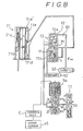
- An automatic transmission 1 as shown in Fig.2 and 3, has a torque converter 2, a planetary transmission gear mechanism 3 and a hydraulic control device 5 which are housed in a converter housing 6, a transmission case 7, an extension housing 9, a valve body 10 and an oil pan 11.
- the torque converter 2 has a lock-up clutch 12, so that rotation of an input member 13 is transmitted to an input shaft 15 of the transmission gear mechanism 3 through hydraulic flow of the torque converter 2 or the lock-up clutch 12.
- the shift gear mechanism 3 comprises a main transmission unit 21 including an over-drive planetary gear unit 17, a front planetary gear unit 19 and a rear planetary gear unit 20.
- the over-drive planetary gear unit 17 comprises a planetary pinion 22, a carrier 24 which is directly connected to the input shaft 15 and supports the pinion 22, a sun gear 23 which encloses the input shaft 15, and a ring gear 25 which is connected to an input shaft 26 of the main transmission mechanism 21.
- An over-drive direct clutch C0 and a one way clutch F0 are situated between the carrier 24 and the sun gear 23, and an over-drive brake B0 is situated between the sun gear 23 and the case 7.
- the front planetary gear unit 19 comprises a planetary pinion 28, a carrier 29 which is directly connected to an output shaft 27 and supports the pinion 28, a sun gear 30a which encloses the output shaft 27 and is constituted integrally with a sun gear 30b of the rear planetary gear unit 20, and a ring gear 31 which is connected to the input shaft 26 through a forward clutch C1.
- a direct clutch C2 is situated between the input shaft 26 and the sun gear 30, a second-coast brake B1 composed of a band brake is situated between the sun gear 30 and the case 7, a one-way clutch F1 and a second brake B2 are radially situated between the sun gear 30 and the case 7.
- the rear planetary gear unit 20 comprises a planetary pinion 32, a carrier 33 which supports the pinion 32, a sun gear 30b, and a ring gear 35 which directly connects to the output shaft 27.
- a first & reverse brake B3 and a one-way clutch F2 are situated radially between the carrier 33 and the case 7.
- 36 in Fig.2 is an oil pump.
- 38 is an output shaft rotation sensor, and 39 is a rotation output gear for speedometer.
- the one-way clutch F0 is situated between a boss 23a of the sun gear 23 and a sleeve 24a of the carrier 24.
- a flange member 40 which constitutes a cylinder is extended from the bass 23a.
- the flange member 40 encloses a piston member 41 to form an hydraulic actuator of the clutch C0, the over-drive direct clutch C0 is situated between the sleeve 24a and an inner surface of the flange 40.
- the over-drive brake B0 is situated between an outer surface of the flange 40 and the case 7.
- a brim 42 is fixed on a peripheral part of the flange 40.
- a non-contacting type sensor 45 such as employing light or magnetic and the like is situated on the case 7 so that the sensor 45 faces plural through holes or slits which are formed on the brim 42.
- the sensor 45 is situated to detect rotation speed of the clutch C0, in other words, to detect rotation speed of the brim 42 which rotates together with the input member 15 at the first, second and third speeds.
- C0, C1 and C2 are hydraulic servos for each clutch
- B0, B1, B2 and B3 are hydraulic servos for each brake
- 2 is a torque converter
- 36 is an oil pump.
- 45 is a speed sensor
- 51 is a manual valve where a line pressure port p is connected to ports a, b, c and d which corresponds to ranges of R, P, N, D, S and L, as shown in the table in Fig.4.
- 52 is a primary regulator valve
- 53 is a throttle valve
- 55 is a secondary regulator valve
- 56 is a lock-up control valve
- 57 is a lock-up relay valve
- 58 is a solenoid relay valve
- 59 is a cutback valve.
- 60 is a 1-2 shift valve
- 61 is a 2-3 shift valve
- 62 is a 3-4 shift valve
- 63 is a reverse inhibit valve
- 65 is a low-coast modulator valve
- 66 is a second-coast modulator valve.
- 67 is an accumulator for the clutch C0
- 70 is an accumulator for the clutch C2
- 71 is an accumulator for the brake B2.
- 72 is an accumulator control valve which regulates hydraulic pressure applied to back pressure chamber 69a, 70a and 71a of the accumulator 69, 70 and 71.
- S1, S2 and S3 are solenoid valves to control the shift valves 60, 61 and 62.
- S4 is a linear solenoid valve, the S4 regulates hydraulic pressure from a solenoid regulator valve 73, and the regulated pressure is applied to the accumulator control valve 72.
- An accumulator control valve 72 has a line pressure port p1, a back-up port p2, a regulating port h connected to back pressure chambers 71a, 70a, 69a of accumulators 71, 70, 69, a feedbakc port i, a control port j which hydraulic pressure from a linear solenoid valve S4 is applied, a drain port ex and a spring 72b which press one end of a spool 72a.
- the linear solenoid valve S4 is controlled by a control unit C based on an electric signal from a sensor 45 which detects a C0 rotation, or rotation speed of the sun gear 23 of the over-drive planetary gear unit 17.
- the solenoid valve S4 has ports j1, j2 which are connected to the port j of the accumulator control valve 72, a port k1 which is connected to a regulating port k of a solenoid modulator valve 73, a port p3 which the line pressure is applied other than a regulating port k, so that the line pressure is reduced at required to the port k1 of the solenoid valve S4.
- the B2 accumulator 71 has an accumulator chamber 71b, a back pressure chamber 71a having small area, and springs 71d, 71e having certain spring constants are compressedly situated at both ends of a piston 71c.
- the back pressure chamber 71a is hydraulically connected to the port h of the control valve 72, while the accumulator chamber 71b is hydraulically connected to the second brake hydraulic servo B2 through the orifice 80 and the check ball 81, and the chamber 71b is connected to the port m of the 1-2 shift valve 60.
- hydraulic pressure from the solenoid valve S2 works on a spool-top chamber p4 to switch a spool 60a.
- the spool 60a When the valve S2 is ON, the spool 60a is at the left-half position (the second, third and fourth speeds), then the line pressure port p5 and the port m are through, while when the valve S2 is OFF, the spool 60a is at the right-half position (the first speed), the port p5 and the port m are disconnected, and the port m is connected to the drain port ex.
- an over-drive brake accumulator 69 has an accumulator chamber 69b, a back pressure chamber 69a, and a spring 69d having certain spring constant is compressedly situated at opposite side of the accumulator chamber 69b.
- the back pressure chamber 69a is hydraulically connected to the port h of the accumulator control valve 72
- the accumulator chamber 69b is hydraulically connected to the over-drive brake hydraulic servo B0 through an orifice and a check ball, and connected to certain port of the 3-4 shift valve 62.
- the accumulator 70 for the direct clutch C2 has an accumulator chamber 70b, and a back pressure chamber 70a having small area, and spring 70d, 70e having certain spring constants are compressedly situated at both ends of piston 70c.
- the back pressure chamber 70a is hydraulically connected to the port h, while the accumulator chamber 70b is hydraulically connected to the direct clutch hydraulic servo C2 through an orifice and a check ball, and connected to a certain port of the 2-3 shift valve 61 (the port m which the line pressure is applied at the left-half position of the valve 61 or certain port o (Fig.4) of the reverse inhibit valve 63 through a mutual switching valve 75.
- the accumulators 71, 69 and 70 for the second brake hydraulic servo B2, the over-drive brake hydraulic servo B0 and the direct clutch hydraulic servo C2 are controlled by one accumulator control valve 72 and the solenoid valve S4 through each back pressure chamber 71a, 69a and 71a, however, these servos are not engaged at the same time.
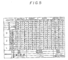
- the solenoid valves S1, S2 and S3; the clutches C0, C1and C2; the brakes B0, B1, B2 and B3; the one-way clutches F0, F1 and F2; are operated at the positions of P, R, R(speed is more than 7 km/h), N, D, 2 and L ranges, as shown in Fig.5.
- the solenoid valve S1 is ON, so that the over-drive direct clutch C0, the one-way clutch F0, F2 and the forward clutch C1 are engaged, other elements are all released. Accordingly, all elements of the over-drive planetary gear unit 17 rotates together through the clutch C0 and the one-way clutch F0, thus rotation of the input shaft 15 is transmitted the input shaft 26 of the main transmission unit 21 without reducing rotation speed.
- rotation of the input shaft 26 is transmitted to the ring gear 31 of the front planetary gear unit 19, and transmitted to the carrier 29 and the output shaft 27 which is integrally connected with the carrier 29.
- the solenoid valve S2 is ON in addition to the solenoid valve S1.
- the over-drive direct clutch C0, the one-way clutch F0, the forward clutch C1, the one-way clutch F1 and the second brake B2 are engaged, and other elements are all released. Accordingly, the over-drive planetary gear 17 is still kept under the direct operating condition, the rotation of the input shaft 15 is transmitted to the input shaft 26 without reducing rotation speed.
- rotation of the input shaft 26 is transmitted to the ring gear 31 through the forward clutch C1, and the sun gear 30 is provided with torque in the left rotational direction through the pinion 28.
- the sun gear 30 is restrained in the left rotational direction by the operation of the one-way clutch F1 because of engagement of the brake B2, consequently, the planetary pinion 28 rotates and the carrier 29 rotates. Then the rotation of the carrier 29 is directly transmitted to the output shaft 27, namely the rotation is transmitted only through the front gear unit 19 to the output shaft 27.
- a shifting signal is sent after certain moment when shifting judgement is made, when friction plates of the second brake B2 start to contact by application of hydraulic pressure to the B2 hydraulic servo, the output torque varies, as a result, rotation speed of the flange 40 which rotates together with the input shaft 15 also varies.
- the varied rotation is detected by the sensor 45 so that an actual rotation Nco is nearly equal to a target rotation Nco*.
- the solenoid valve S4 is controlled by the electric signals of the control unit C based on the signals of the sensor 45.
- hydraulic pressure applied from the solenoid modulator valve 73 is regulated in the solenoid valve S4 and such regulated pressure is taken from the ports j1, j2 as a certain control hydraulic pressure, the certain control pressure is applied to the port j of the accumulator control valve 72.
- the control valve 72 is under the right-half position (Fig.1) by hydraulic pressure being applied to the back up port p2 through an orifice 80, and the line pressure applied from the port p1 is taken out from the port h to apply to the back pressure chamber 71a of the accumulator 71, from the above state of the control valve 72, the control pressure from the port h works to a bulged section of the spool, and the pressure, with the pressing force of the spring 72b, moves the spool against the line pressure of the back up port p2. Consequently the line pressure of the port p1 is reduced in accordance with the control pressure and taken out from the port h.
- the reduced pressure works from the feedback port i to a lower part of the spool 72a, at the same time the reduced pressure is applied to the back pressure chamber 71b of the accumulator 71. Because of these motions, the accumulator back pressure D as shown in Fig.6 (d) is reduced by certain volume so that an excessive rise of the output torque A′ as shown in Fig.6 (b) is not happened.
- the accumulator back pressure as shown in E of Fig.6 (d), is feedback controlled so that the rotation of the flange 40 Nco (hereinafter called C0 rotation) is to be the target rotation Nco*.
- the solenoid valve S1 is OFF, the 2-3 shift valve 61 is switched to the left-half position (Fig.4).
- the over-drive direct clutch C0, the one-way clutch F0, the forward clutch C1, the direct clutch C2 and the second brake B2 are engaged, and other elements are all released.
- the over-drive planetary gear unit 17 is under the direct operating condition, and in the main transmission mechanism 21, the elements of the front planetary gear unit 19 rotate together because the clutch C1 and C2 are engaged, thus rotation of the input shaft 26 is transmitted to the output shaft 27 without reducing rotation speed.
- the 2-3 shift valve 61 is switched due to the solenoid valve S1 being OFF, the line pressure from the port m′ is applied to the direct clutch hydraulic servo C2, at this moment, the line pressure is also applied to the accumulator chamber 70b of the C2 accumulator 70.
- the linear solenoid valve S4 is controlled based on the signals from the speed sensor 45 so that the accumulator back pressure is controlled as shown in Fig.6 (d).
- the hydraulic pressure of the C2 hydraulic serve rises as shown in Fig.6 (c). Shift shock is reduced when shifting from the second to the third speed as same as the shifting from the first to the second speed.
- the solenoid valve S2 is also OFF, the 3-4 shift valve 62 is switched to the left-half position.
- the forward clutch C1, the direct clutch C2, and the second brake B2 are engaged.
- the main transmission mechanism 21, as same as the third speed, is under the direct operating condition, while at the over-drive planetary gear unit 17, the direct clutch C0 is released and the over-drive brake B0 is engaged. Accordingly, the sun gear 23 is locked by the brake B0, the planetary pinion 22 rotates with the carrier 24 which also rotates, then rotation is transmitted to the ring gear 25 as an over-drive rotation, the over-drive rotation is transmitted to the input shaft 26 of the main transmission mechanism 21 which is under the direct operating condition.
- the over-drive direct clutch C0 When down shifting from the fourth to the third speed; the over-drive direct clutch C0 is engaged and the over-drive brake B0 is released.
- the direct clutch C2 When down shifting from the third to the second speed, the direct clutch C2 is released, furthermore when shifting down from the second to the first speed, the second brake B2 is released.
- the linear solenoid valve S4 is controlled by the electric signals from the control unit C based on the speed sensor 45, thus the accumulator back pressure working on the back pressure chambers 69a of the B0 accumulator 69, 70a of the C2 accumulator and 71a of the B2 accumulator 71 are reduced by certain timing and certain time. Due to these motions, shift shock is reduced when down shifting as same as up-shifting, so that shifting operation is performed smoothly.
- the second-coast brake B1 At the second speed of the second and L ranges; the second-coast brake B1 is engaged, the sun gear 30 of the main transmission mechanism 21 is restrained, so that the engine-brake is actuated.
- the over-drive clutch C0, the one-way clutch F0, the direct clutch C2 and the first & reverse brake B3 are engaged, and other elements are all released. Accordingly the over-drive planetary gear unit 17 is under the direct operating condition, and in the main transmission mechanism 21, rotation of the input shaft 26 is directly transmitted to the sun gear 30 through the clutch C2, and as the carrier 33 is restrained by the brake B3, the rotation of the sun gear 30 is transmitted to the ring gear 35 as reverse rotation through the pinion 32 which rotates, thus the output shaft 27 rotates reversely.
- a throttle pressure P th of a throttle valve 53 is employed as a hydraulic pressure source to apply to the accumulator control valve 72.
- regulated pressure from the linear solenoid valve S4 works on the control port j of the control valve 72
- the throttle pressure at the throttle application port t1 is reduced per certain volume, then the reduced pressure is applied to the back pressure chamber of the accumulator.
- the B0 accumulator 69 and the C2 accumulator 70 are controlled as well as the B2 accumulator 71.
- the regulated hydraulic pressure from the linear solenoid valve S4 is directly applied to a back pressure chamber 71a′.
- the control pressure ports j1, j2 apply certain hydraulic pressure to the accumulator back pressure chamber 71a′, and when the speed sensor 45 detects speed change, the linear solenoid valve S4 is controlled to reduce certain volume of hydraulic pressure by certain timing.
- the engine-brake control device is also applicable to the Ravigneaux type transmission unit.
- the hydraulic pressure of the accumulator back pressure chamber (71a), (70a), (69a) is controlled by the sensor (45) which detects the rotation speed which varies at shifting of the shift valve, so that engaging and releasing of the frictional engaging elements (B2), (C2), (B0) are adequately controlled to make the change of output torque smooth, and to reduce the shift shocks at shifting. Furthermore, it is possible for the control of the accumulator back pressure chamber to control the hydraulic pressure in different manner for the up-shifting and the down-shifting, so that the shift shock at down-shifting are reduced as well as that of the up-shifting.
- a member whose rotation speed is detected by the sensor (45) is the member (40, 42) which rotates by the engagement of the frictional engaging element (C0) which varies its rotation speed at each sifting stage and stops at the highest shifting stage; the member (40, 42) is located at the input side where precise rotating speed change is detected at shifting, while the member is located near the case, so detection is easily and precisely conducted. Furthermore, as the shifting comes to the higher stage, the change of rotating speed becomes small, it is difficult to detect the timing of the highest shifting stage. However, the member (40) stops at the highest shifting stage based on the release of the frictional engaging element (C0), so that the timing of the highest shifting stage (4th speed) is precisely and correctly detected due to a large rotational change (stopping).
- accumulators In the case that a plurality of accumulators (71), (70), (69) which are not engaged at the same time are controlled by one regulating valve (S4), these accumulators are controlled through plural shifting stages by such a simple structure utilizing the regulating valve (S4).
- accumulators are a second brake accumulator (71), a direct clutch accumulator (70) and an over-drive accumulator (69); over all shifting stages, or between the first and second speeds, the second and the third speeds, the third and fourth speeds, accumulator control can be preformed.
Landscapes
- Engineering & Computer Science (AREA)
- General Engineering & Computer Science (AREA)
- Physics & Mathematics (AREA)
- Fluid Mechanics (AREA)
- Mechanical Engineering (AREA)
- Control Of Transmission Device (AREA)
Applications Claiming Priority (2)
| Application Number | Priority Date | Filing Date | Title |
|---|---|---|---|
| JP63037882A JP2911120B2 (ja) | 1988-02-20 | 1988-02-20 | 自動変速機における油圧制御装置 |
| JP37882/88 | 1988-02-20 |
Publications (3)
| Publication Number | Publication Date |
|---|---|
| EP0330408A2 true EP0330408A2 (fr) | 1989-08-30 |
| EP0330408A3 EP0330408A3 (en) | 1990-08-29 |
| EP0330408B1 EP0330408B1 (fr) | 1995-04-26 |
Family
ID=12509909
Family Applications (1)
| Application Number | Title | Priority Date | Filing Date |
|---|---|---|---|
| EP89301633A Expired - Lifetime EP0330408B1 (fr) | 1988-02-20 | 1989-02-20 | Dispositif de commande hydraulique pour une transmission automatique |
Country Status (4)
| Country | Link |
|---|---|
| US (1) | US5109733A (fr) |
| EP (1) | EP0330408B1 (fr) |
| JP (1) | JP2911120B2 (fr) |
| DE (1) | DE68922328T2 (fr) |
Cited By (7)
| Publication number | Priority date | Publication date | Assignee | Title |
|---|---|---|---|---|
| EP0337494A2 (fr) * | 1988-04-15 | 1989-10-18 | Nissan Motor Co., Ltd. | Système de contrôle de la pression de la conduite pour transmission automatique |
| EP0498481A1 (fr) * | 1991-02-07 | 1992-08-12 | General Motors Corporation | Méthode de commande pour passer en deux états transitoires à des rapports supérieurs dans une transmission automatique |
| EP0588627A1 (fr) * | 1992-09-16 | 1994-03-23 | Hitachi, Ltd. | Système de commande de la force d'entraînement d'un véhicule |
| US6569050B2 (en) * | 1999-12-27 | 2003-05-27 | Aisin Aw Co., Ltd. | Hydraulic control apparatus for an automatic transmission |
| DE19733127B4 (de) * | 1996-07-31 | 2009-08-27 | Jatco Ltd, Fuji | Hochschaltsteuervorrichtung für ein automatisches Getriebe |
| DE19733182B4 (de) * | 1996-07-31 | 2009-08-27 | Jatco Ltd, Fuji | Vorrichtung zur Steuerung eines Herunterschaltvorganges eines automatischen Getriebes |
| CN102606322A (zh) * | 2012-03-28 | 2012-07-25 | 中联重科股份有限公司 | 一种发动机节能控制方法、节能控制器、系统及工程机械 |
Families Citing this family (7)
| Publication number | Priority date | Publication date | Assignee | Title |
|---|---|---|---|---|
| JP2821645B2 (ja) * | 1990-06-20 | 1998-11-05 | トヨタ自動車株式会社 | 自動変速機の変速制御装置 |
| JP3401268B2 (ja) * | 1992-03-06 | 2003-04-28 | ジヤトコ株式会社 | 自動変速機のクラッチ制御方法及び装置 |
| JP3149628B2 (ja) * | 1993-06-11 | 2001-03-26 | 三菱自動車工業株式会社 | 車両用自動変速機 |
| US5393273A (en) * | 1993-06-21 | 1995-02-28 | General Motors Corporation | Powertrain and control having a plurality of accumulators |
| US5540628A (en) * | 1994-11-02 | 1996-07-30 | Younger; Gilbert W. | Methods and systems for improving the operation of transmissions for motor vehicles |
| DE10218105A1 (de) * | 2001-04-25 | 2002-11-21 | Aisin Aw Co | Hydraulische Drucksteuervorrichtung eines Automatikgetriebes |
| US7486996B2 (en) * | 2005-09-26 | 2009-02-03 | Eaton Corporation | Transmission control unit having pressure transducer package |
Citations (4)
| Publication number | Priority date | Publication date | Assignee | Title |
|---|---|---|---|---|
| JPS61130653A (ja) * | 1984-11-28 | 1986-06-18 | Nissan Motor Co Ltd | 自動変速機の変速シヨツク軽減装置 |
| JPS61149657A (ja) * | 1984-12-21 | 1986-07-08 | Toyota Motor Corp | 車両用自動変速機の油圧制御装置 |
| US4722250A (en) * | 1985-07-31 | 1988-02-02 | Aisin-Warner Kabushiki Kaisha | Accumulator back pressure control apparatus for automatic transmission |
| EP0279606A2 (fr) * | 1987-02-19 | 1988-08-24 | Toyota Jidosha Kabushiki Kaisha | Commande hydraulique pour transmission automatique |
Family Cites Families (7)
| Publication number | Priority date | Publication date | Assignee | Title |
|---|---|---|---|---|
| JPS6141065A (ja) * | 1984-07-31 | 1986-02-27 | Aisin Warner Ltd | 車両用自動変速機の油圧制御装置 |
| JPS61266857A (ja) * | 1985-05-21 | 1986-11-26 | Toyota Motor Corp | 車両用自動変速機の油圧制御装置 |
| JPS6262047A (ja) * | 1985-09-11 | 1987-03-18 | Nissan Motor Co Ltd | 自動変速機のショック軽減装置 |
| JPS62255645A (ja) * | 1986-04-25 | 1987-11-07 | Toyota Motor Corp | 自動変速機の油圧制御装置 |
| JPH0788898B2 (ja) * | 1986-07-01 | 1995-09-27 | アイシン・エィ・ダブリュ株式会社 | 自動変速機における油圧サ−ボ調圧装置 |
| JP2735116B2 (ja) * | 1986-07-01 | 1998-04-02 | アイシン・エィ・ダブリュ株式会社 | 自動変速機における油圧制御装置 |
| US4843917A (en) * | 1988-07-11 | 1989-07-04 | Ford Motor Company | Accumulator control for hydraulic actuating pressure of automatic transmission friction clutch or brake |
-
1988
- 1988-02-20 JP JP63037882A patent/JP2911120B2/ja not_active Expired - Lifetime
-
1989
- 1989-02-20 EP EP89301633A patent/EP0330408B1/fr not_active Expired - Lifetime
- 1989-02-20 DE DE68922328T patent/DE68922328T2/de not_active Expired - Lifetime
- 1989-02-21 US US07/313,233 patent/US5109733A/en not_active Expired - Lifetime
Patent Citations (4)
| Publication number | Priority date | Publication date | Assignee | Title |
|---|---|---|---|---|
| JPS61130653A (ja) * | 1984-11-28 | 1986-06-18 | Nissan Motor Co Ltd | 自動変速機の変速シヨツク軽減装置 |
| JPS61149657A (ja) * | 1984-12-21 | 1986-07-08 | Toyota Motor Corp | 車両用自動変速機の油圧制御装置 |
| US4722250A (en) * | 1985-07-31 | 1988-02-02 | Aisin-Warner Kabushiki Kaisha | Accumulator back pressure control apparatus for automatic transmission |
| EP0279606A2 (fr) * | 1987-02-19 | 1988-08-24 | Toyota Jidosha Kabushiki Kaisha | Commande hydraulique pour transmission automatique |
Cited By (17)
| Publication number | Priority date | Publication date | Assignee | Title |
|---|---|---|---|---|
| EP0337494B1 (fr) * | 1988-04-15 | 1995-11-29 | Nissan Motor Co., Ltd. | Système de contrôle de la pression de la conduite pour transmission automatique |
| EP0337494A2 (fr) * | 1988-04-15 | 1989-10-18 | Nissan Motor Co., Ltd. | Système de contrôle de la pression de la conduite pour transmission automatique |
| EP0498481A1 (fr) * | 1991-02-07 | 1992-08-12 | General Motors Corporation | Méthode de commande pour passer en deux états transitoires à des rapports supérieurs dans une transmission automatique |
| US5776030A (en) * | 1992-09-16 | 1998-07-07 | Hitachi, Ltd. | Driving force control system for a vehicle |
| US5792021A (en) * | 1992-09-16 | 1998-08-11 | Hitachi, Ltd. | Axle torque estimating system for a vehicle equipped with an automatic transmission system, and axle torque controlling system |
| US5573476A (en) * | 1992-09-16 | 1996-11-12 | Hitachi, Ltd. | Driving force control system for a vehicle |
| EP0715099A3 (fr) * | 1992-09-16 | 1998-01-07 | Hitachi, Ltd. | Système de commande de la force d'entraínement d'un véhicule |
| US5772555A (en) * | 1992-09-16 | 1998-06-30 | Hitachi, Ltd. | Driving force control system for a vehicle |
| EP0588627A1 (fr) * | 1992-09-16 | 1994-03-23 | Hitachi, Ltd. | Système de commande de la force d'entraînement d'un véhicule |
| US5779594A (en) * | 1992-09-16 | 1998-07-14 | Hitachi, Ltd. | Driving force control system for a vehicle |
| EP0715099A2 (fr) * | 1992-09-16 | 1996-06-05 | Hitachi, Ltd. | Système de commande de la force d'entraînement d'un véhicule |
| US6077191A (en) * | 1992-09-16 | 2000-06-20 | Hitachi, Ltd. | Driving force control system using target driving torque, gear ratio and inertial torque to determine engine torque during shifting |
| US6090011A (en) * | 1992-09-16 | 2000-07-18 | Hitachi, Ltd. | Driving force control system for a vehicle |
| DE19733127B4 (de) * | 1996-07-31 | 2009-08-27 | Jatco Ltd, Fuji | Hochschaltsteuervorrichtung für ein automatisches Getriebe |
| DE19733182B4 (de) * | 1996-07-31 | 2009-08-27 | Jatco Ltd, Fuji | Vorrichtung zur Steuerung eines Herunterschaltvorganges eines automatischen Getriebes |
| US6569050B2 (en) * | 1999-12-27 | 2003-05-27 | Aisin Aw Co., Ltd. | Hydraulic control apparatus for an automatic transmission |
| CN102606322A (zh) * | 2012-03-28 | 2012-07-25 | 中联重科股份有限公司 | 一种发动机节能控制方法、节能控制器、系统及工程机械 |
Also Published As
| Publication number | Publication date |
|---|---|
| EP0330408B1 (fr) | 1995-04-26 |
| EP0330408A3 (en) | 1990-08-29 |
| JP2911120B2 (ja) | 1999-06-23 |
| DE68922328T2 (de) | 1995-10-12 |
| US5109733A (en) | 1992-05-05 |
| JPH01216151A (ja) | 1989-08-30 |
| DE68922328D1 (de) | 1995-06-01 |
Similar Documents
| Publication | Publication Date | Title |
|---|---|---|
| US4513639A (en) | Creeping preventing apparatus in automatic transmission for vehicle | |
| US4485695A (en) | Control apparatus for automatic transmissions | |
| US4662488A (en) | Control system for a clutch interposed between input and output shafts of hydrodynamic power transmitting device | |
| US4561328A (en) | Creeping preventing apparatus in automatic transmission for vehicle | |
| JP2921764B2 (ja) | 自動変速機の液圧制御装置 | |
| EP0330408A2 (fr) | Dispositif de commande hydraulique pour une transmission automatique | |
| US4722251A (en) | Hydraulic circuit for controlling an automatic transmission | |
| US4628774A (en) | Transmission control system including select shock suppressing arrangement | |
| US5275069A (en) | Control system for automatic transmission | |
| JP3103568B2 (ja) | 自動変速機における油圧制御装置 | |
| US5537887A (en) | Hydraulic control system for 4-speed automatic transmission | |
| US4367812A (en) | Control apparatus for torque converter direct coupling clutch in automatic transmissions | |
| JPS6318056B2 (fr) | ||
| JPH0121379B2 (fr) | ||
| EP0330409A2 (fr) | Dispositif de commande de freinage moteur pour transmission automatique | |
| US5010788A (en) | Automatic automotive transmission having 4-2 downshift sequence valve | |
| JPS627428B2 (fr) | ||
| JPS61103040A (ja) | 自動変速機の油圧制御装置 | |
| US5121656A (en) | Shift control system for an automatic transmission | |
| KR950007266B1 (ko) | 자동 변속기의 변속 제어장치 | |
| JP2798252B2 (ja) | 自動変速機におけるシフト制御装置 | |
| JPS6038583B2 (ja) | 自動変速機の油圧制御装置 | |
| JP3005338B2 (ja) | 自動変速機の制御装置 | |
| JPH0533860A (ja) | 自動変速機の変速制御装置 | |
| JPS5825902B2 (ja) | 自動変速機の油圧制御装置 |
Legal Events
| Date | Code | Title | Description |
|---|---|---|---|
| PUAI | Public reference made under article 153(3) epc to a published international application that has entered the european phase |
Free format text: ORIGINAL CODE: 0009012 |
|
| AK | Designated contracting states |
Kind code of ref document: A2 Designated state(s): DE FR GB |
|
| PUAL | Search report despatched |
Free format text: ORIGINAL CODE: 0009013 |
|
| AK | Designated contracting states |
Kind code of ref document: A3 Designated state(s): DE FR GB |
|
| 17P | Request for examination filed |
Effective date: 19910227 |
|
| 17Q | First examination report despatched |
Effective date: 19920924 |
|
| GRAA | (expected) grant |
Free format text: ORIGINAL CODE: 0009210 |
|
| AK | Designated contracting states |
Kind code of ref document: B1 Designated state(s): DE FR GB |
|
| ET | Fr: translation filed | ||
| REF | Corresponds to: |
Ref document number: 68922328 Country of ref document: DE Date of ref document: 19950601 |
|
| PLBE | No opposition filed within time limit |
Free format text: ORIGINAL CODE: 0009261 |
|
| STAA | Information on the status of an ep patent application or granted ep patent |
Free format text: STATUS: NO OPPOSITION FILED WITHIN TIME LIMIT |
|
| 26N | No opposition filed | ||
| REG | Reference to a national code |
Ref country code: GB Ref legal event code: IF02 |
|
| PGFP | Annual fee paid to national office [announced via postgrant information from national office to epo] |
Ref country code: GB Payment date: 20080220 Year of fee payment: 20 Ref country code: DE Payment date: 20080214 Year of fee payment: 20 |
|
| PGFP | Annual fee paid to national office [announced via postgrant information from national office to epo] |
Ref country code: FR Payment date: 20080208 Year of fee payment: 20 |
|
| REG | Reference to a national code |
Ref country code: GB Ref legal event code: PE20 Expiry date: 20090219 |
|
| PG25 | Lapsed in a contracting state [announced via postgrant information from national office to epo] |
Ref country code: GB Free format text: LAPSE BECAUSE OF EXPIRATION OF PROTECTION Effective date: 20090219 |