EP0709501A2 - Procédé pour remplacer des pots entre un chariot de transport pour pots plats et un métier à filer à bout libre et chariot de transport pour la mise en oeuvre de ce procédé - Google Patents
Procédé pour remplacer des pots entre un chariot de transport pour pots plats et un métier à filer à bout libre et chariot de transport pour la mise en oeuvre de ce procédé Download PDFInfo
- Publication number
- EP0709501A2 EP0709501A2 EP95120117A EP95120117A EP0709501A2 EP 0709501 A2 EP0709501 A2 EP 0709501A2 EP 95120117 A EP95120117 A EP 95120117A EP 95120117 A EP95120117 A EP 95120117A EP 0709501 A2 EP0709501 A2 EP 0709501A2
- Authority
- EP
- European Patent Office
- Prior art keywords
- sliver
- tape
- flat
- spinning
- feeder
- Prior art date
- Legal status (The legal status is an assumption and is not a legal conclusion. Google has not performed a legal analysis and makes no representation as to the accuracy of the status listed.)
- Granted
Links
Images


Classifications
-
- D—TEXTILES; PAPER
- D01—NATURAL OR MAN-MADE THREADS OR FIBRES; SPINNING
- D01H—SPINNING OR TWISTING
- D01H9/00—Arrangements for replacing or removing bobbins, cores, receptacles, or completed packages at paying-out or take-up stations ; Combination of spinning-winding machine
- D01H9/18—Arrangements for replacing or removing bobbins, cores, receptacles, or completed packages at paying-out or take-up stations ; Combination of spinning-winding machine for supplying bobbins, cores, receptacles, or completed packages to, or transporting from, paying-out or take-up stations ; Arrangements to prevent unwinding of roving from roving bobbins
- D01H9/185—Transporting cans
-
- B—PERFORMING OPERATIONS; TRANSPORTING
- B65—CONVEYING; PACKING; STORING; HANDLING THIN OR FILAMENTARY MATERIAL
- B65H—HANDLING THIN OR FILAMENTARY MATERIAL, e.g. SHEETS, WEBS, CABLES
- B65H67/00—Replacing or removing cores, receptacles, or completed packages at paying-out, winding, or depositing stations
- B65H67/04—Arrangements for removing completed take-up packages and or replacing by cores, formers, or empty receptacles at winding or depositing stations; Transferring material between adjacent full and empty take-up elements
- B65H67/0428—Arrangements for removing completed take-up packages and or replacing by cores, formers, or empty receptacles at winding or depositing stations; Transferring material between adjacent full and empty take-up elements for cans, boxes and other receptacles
-
- D—TEXTILES; PAPER
- D01—NATURAL OR MAN-MADE THREADS OR FIBRES; SPINNING
- D01H—SPINNING OR TWISTING
- D01H15/00—Piecing arrangements ; Automatic end-finding, e.g. by suction and reverse package rotation; Devices for temporarily storing yarn during piecing
-
- D—TEXTILES; PAPER
- D01—NATURAL OR MAN-MADE THREADS OR FIBRES; SPINNING
- D01H—SPINNING OR TWISTING
- D01H9/00—Arrangements for replacing or removing bobbins, cores, receptacles, or completed packages at paying-out or take-up stations ; Combination of spinning-winding machine
- D01H9/005—Arrangements for replacing or removing bobbins, cores, receptacles, or completed packages at paying-out or take-up stations ; Combination of spinning-winding machine for removing empty packages or cans and replacing by completed (full) packages or cans at paying-out stations; also combined with piecing of the roving
- D01H9/008—Arrangements for replacing or removing bobbins, cores, receptacles, or completed packages at paying-out or take-up stations ; Combination of spinning-winding machine for removing empty packages or cans and replacing by completed (full) packages or cans at paying-out stations; also combined with piecing of the roving for cans
-
- B—PERFORMING OPERATIONS; TRANSPORTING
- B65—CONVEYING; PACKING; STORING; HANDLING THIN OR FILAMENTARY MATERIAL
- B65H—HANDLING THIN OR FILAMENTARY MATERIAL, e.g. SHEETS, WEBS, CABLES
- B65H2701/00—Handled material; Storage means
- B65H2701/30—Handled filamentary material
- B65H2701/31—Textiles threads or artificial strands of filaments
Definitions
- the present invention relates to a method for automatically applying a fiber sliver to a textile machine or device having a feed device, and to a device for carrying out this method.
- the object of the present invention is therefore to provide a method and a device which ensure that the sliver can be safely introduced into the feed device of the textile machine or device and the work of the machine or device can be continued without or only with a slight interruption.
- This object is achieved in that the end of the sliver is brought into a defined receiving position, in which the end of the sliver is taken up as the beginning of the sliver and transferred to the feed device. Since the sliver is in a defined position for picking it up, the receiving device is always picked up in the same position and can therefore also be handled in the same way. This handling allows the sliver to be brought into a defined state and in a defined position in relation to the feed device, so that the transfer and insertion into the feed device of the textile machine, ie the application, can be carried out safely and quickly without difficulty.
- a “textile machine” is to be understood as any textile machine that processes fiber slivers. These include e.g. Draw frames and spinning machines such as ring, air, false-wire and open-end spinning machines, but other textile machines to which fiber slivers are fed for processing can also be suitable, such as Circular knitting machines to which fiber tapes are fed for the production of pile fabrics and carpets.
- Working elements can thus be a drafting system (e.g. on a draw frame or air spinning machine), a spindle (e.g. on a ring spinning machine), an opening roller (on an open-end spinning machine), a needle cylinder (on a circular knitting machine) and the like.
- the place where these organs are located is referred to below as the job.
- a textile machine in which the subject matter of the invention can be used has more than one job, but the invention is not restricted to this.
- sliver should be understood to mean any sliver composed of fibers, irrespective of whether the sliver has a certain rotation, as is the case with sliver, or not.
- feeding device in the sense of the present invention is considered that device that takes up the sliver and feeds the working organ of the textile machine.
- this readiness position (or else the receiving position) is provided on a can to be fed to the textile machine. Differences are also possible here.
- a standby or receiving position in the center of the jug or alternatively in its peripheral area outside the jug has proven to be particularly useful.
- the sliver end protruding downwards in or on the can has a length of at least 100 mm and a maximum of 200 mm. Deviating tape end lengths are also possible, but either make it more difficult to take up and / or require a longer excess tape section to be cut off, so that avoidable fiber loss occurs.
- the end of the tape is brought into the standby position provided on the jug as soon as the filling of the jug is finished, and that the sliver is then moved to the receiving position on the jug by transporting the jug into the receiving position Feeder is brought.
- the sliver remains under control from the filling to the feeding device, ie also during transport.
- the sliver In order to create a simple way of receiving the sliver placed over the edge of the can, the sliver should always be located at one and the same point on the circumference of the can. In order to achieve this, it is expediently provided that the end of the strip is deposited in the center of the direction in which the can is pushed out of the filling station on the trailing side of the can. In order to guarantee this defined belt position up to the receiving position in front of the feed device, it is advantageous if the can is transported with the sliver into the receiving location on the relevant feed device and the sliver is secured to the can during transportation thereof.
- the jug with the sling secured to it should also assume a certain relative position with respect to the job when it reaches the feeder of the textile machine. For this reason, it is advantageous if the jug is secured against rotation until it reaches the pick-up position with the beginning of the tape.
- the measures described above can be used to safely pick up the beginning of the tape.
- the recording security is further increased if there is still a length section of the beginning of the tape is brought into a defined path of predetermined length in the ready position and / or the receiving position.
- a pick-up and feed device can reliably detect the end of the tape, the relative position between the start of the tape and the pick-up element being properly secured.
- a length section of the beginning of the tape can be secured in a defined path of predetermined length in various ways. It has proven particularly expedient if the length section of the sliver is clamped in the vicinity of the free end of the sliver start, while the sliver is guided axially movably at the other end of the defined path. In this way, the sliver can be inserted into the feed device without it being necessary to remove the sliver from the guide. If the insertion of the sliver into the feed device fails, the sliver can be found again in a simple manner, since the position of the sliver is predetermined at least in the area of this guide.
- the beginning of the tape is brought into the receiving position above a can supplied to the feed device.
- the start of the tape is advantageously prepared for transfer to the feed device. It is particularly expedient here if the beginning of the tape to be prepared is brought to a defined length.
- the free end of the beginning of the tape protruding from the feeder unit and intended for insertion into the feed device cannot assume any position, as would be the case due to gravity or other influences in the case of a longer, undefined length section, but a defined one Takes position.
- a band section which does not correspond to the desired thickness is cut off from the beginning of the band while it is brought to a defined length.
- the beginning of the tape can also be separated in various ways. It has proven to be particularly advantageous if the beginning of the sliver to be brought to a defined length is produced by pulling the sliver apart.
- the beginning of the sliver is expediently pointed during the preparation of the beginning of the sliver.
- the tape start to be prepared can be rotated around its own axis. Additionally or alternatively, the beginning of the tape to be prepared can be exposed to an air stream.
- the prepared beginning of the tape is expediently solidified in its shape. This can also be done in various ways, for example with the aid of a spray or by freezing. It is particularly advantageous if the beginning of the tape is solidified by applying a predetermined amount Time volatile volatile medium takes place.
- the tape start is expediently introduced directly into the running feed device when it is transferred to the textile machine.
- the feed speed of the beginning of the tape into the feed device is preferably matched to its delivery speed. This can be done in such a way that the beginning of the tape is fed to the feed device at a speed which is less than or at most the same size as the delivery speed of the feed device.
- the sliver When the sliver is fed to the feed device of an open-end spinning device, a successful insertion of the sliver into the feed device is advantageously immediately followed by a piecing process, since in the case of an open-end spinning device the flow of the fiber material is interrupted after a sliver has run out and a thread break has occurred. If fibers are now fed to the spinning element during the re-spinning, these fibers cannot be withdrawn from the spinning element, since they have no connection to a thread yet. In order to be able to obtain a defined attachment point, the sliver must be fed through the feed device until the sliver has reached the desired thickness in the area of the feed device.
- the fibers should not be placed on or in the spinning element, since they would otherwise interfere with the piecing. For this reason, it can be provided in a further advantageous embodiment of the method according to the invention that before the piecing process during the introduction of the sliver, the fibers detached therefrom are prevented from being deposited in or on the spinning element and are instead removed.
- the removal of the unwanted fibers can be achieved according to the invention in that the spinning element is braked continuously or intermittently during the introduction of the sliver into the feed device, so that the fibers supplied by the feed device are removed by the effective spinning vacuum and thereby on a fiber deposit in or on the spinning element are prevented.
- Such a process avoids that the piecing process has to be coordinated with the introduction of the sliver. A possible preparation of the beginning of the sliver is therefore not to be coordinated with the piecing, but only with the introduction of the sliver into the feeding device.
- the fiber sliver is immediately introduced into the feed device when it is transferred to the textile machine.
- the start of the belt is transferred to the textile machine in a waiting position which is offset from the normal belt run, from which it is brought to the feed position in front of the feed device at the desired point in time and is then introduced into the running feed device.
- the transition from the end of the sliver to the new sliver can thus take place very quickly, since it is not necessary to wait until the sliver can be brought to the relevant job with the sliver, but this can can be provided beforehand while the old sliver is running.
- the band request in the waiting position is expediently shifted into the feed position as a function of the outlet of the sliver previously fed to the feed device.
- the beginning of the sliver is brought into the feed position so early that it is fed to the feed device in an overlapping manner with the end of the sliver running out. In this way, the fiber sliver can be introduced into the feed device in such a way that the flow of material is not interrupted in the first place and fiber material can be fed continuously to the work station.
- the beginning of the band in the waiting position is advantageously secured against sliding back.
- the start of the tape brought into the waiting position is expediently monitored and the insertion process is then repeated if the beginning of the tape fails. In this way it is ensured that in the waiting position a belt is always available in time, which can then be fed to the feed device by offset.
- the sliver to be fed is picked up and clamped in a defined position, then cut and brought into a defined shape, whereupon the sliver thus prepared is brought in front of the feed device and inserted therein, a defined length of tape being introduced into the feed device and the insertion success being checked to repeat the insertion process if the beginning of the tape fails.
- a high contact security is achieved because the sliver is given an optimal length and shape by the preparation and is also introduced into the feeding device over a predetermined length.
- the cans at the workplace of the textile machine there is little space for the cans at the workplace of the textile machine.
- the waiting position for a third jug as a reserve jug for the introduction of a sliver is expediently placed behind the two cans of two adjacent feeding devices arranged one behind the other in their workplaces the feeder provided.
- a device for automatically applying a sliver to a textile machine or device includes a sliver in which the sliver can be held in a defined receiving position, as well as a sliver feeder for receiving the sliver presented in the receiving position and for inserting it into the feeder provided.
- the belt feeder can be designed differently and is formed in a simple embodiment by the can in which the sliver to be put on is placed in the feed device.
- a filling station with a tape deposit and a control device for generating a relative movement provided between the sliver and the jug in such a way that the sliver is deposited with the sliver end in a defined position on or in the jug.
- a complicated search for the end of the band for the reception and for the introduction of the same into the feed device possibly a complicated reorientation in the band feeder or in a device upstream of this band feeder, is therefore not necessary. Nevertheless, a safe introduction of the beginning of the sliver into the feeding device of the open-end spinning device is ensured.
- a tape depositor which deposits the tape end in the center of the tape turns in the can is provided for this purpose.
- the end of the tape can be recorded as a new beginning of the tape in various ways. It is advantageous if the belt feeder can be brought into the center of the jug between the belt windings in order to pick up the belt end in a defined manner.
- a tape depositor which deposits the tape end over the edge of the can.
- the belt feeder can be moved along the circumference of the can for the defined reception of the belt end.
- the tape feeder is expediently attached to a can, with a releasable attachment of the sliver on the jug allows the use of conventional jugs.
- the tape feeder as a tape guide, since then the sliver can still perform axial movements in the tape feeder, which is desirable so that the fiber sliver only needs to be removed from the tape feeder at a later time after completion of the tape application.
- a filling station with a sliver and a control device for generating a relative movement between the sliver and the sliver is provided in such a way that the end of the sliver is inserted into the sliver.
- the sliver deposited in the sliver it is not necessary for the sliver deposited in the sliver to be taken up directly by the sliver feeder, through which it is also presented to the feed device of the textile machine.
- the interposition of a tape recorder can prove to be expedient, with this tape recorder having the task of picking up the sliver deposited in a defined position on or in the can and transferring it to the tape feeder as the beginning of the tape .
- the tape pickup can also be brought into the center of the pot between the tape turns.
- the tape receiver can be moved along the circumference of the can.
- the tape receiver and / or tape feeder is designed pneumatically according to an advantageous embodiment of the subject matter of the invention. It has a secure take-up of the sliver and also for a safe transfer of the same to the belt feeders and / or to the feed device, has been found to be advantageous if the belt loader and / or the belt receiver and / or the belt feeder has an essentially tubular base body which is connected to a switchable pressure / vacuum source and which has at its free end a sieve which is adapted in length to the length of the strip end to be gripped and which extends over a partial circumference of the base body.
- the negative pressure is effective, the sliver is taken up while the positive pressure is switched on for the transfer.
- its base body is divided into a plurality of longitudinally extending chambers, each of which is delimited by a separate partial area of the screen and individually, i.e. can be switched to negative pressure or positive pressure independently of the other chambers.
- This ensures both secure tape take-up and secure tape delivery. It is particularly expedient if the air flow in the pneumatic belt depositor and / or belt receiver and / or belt feeder can be controlled as a function of its movement, in particular when the belt is being dispensed.
- the end of the band is at the beginning of the band in a defined position on the can.
- a transport device is expediently provided for the transport of the can from the filling station to the feed device of the textile machine, wherein cooperating guides on the transport device and can ensure that the can is in a certain position to the work station reached.
- the jug and the textile machine likewise have cooperating guides which are expediently arranged in the vicinity of the lower or the upper edge of the jug.
- the guides of the jug can be designed differently. It when the guide of the can is formed by a non-circular outer profile of the can is particularly advantageous.
- the jug preferably has an elongated cross section. As a result, the can can be made narrower than previously customary, so that more cans than before find space next to one another on the machine, which makes it easier to provide cans for a new introduction of the sliver into the feed device soon.
- the dimensions of the cans are advantageously determined according to the invention in such a way that the capacity of the flat can corresponds to the capacity of a conventional round can.
- the capacity of the can with an elongated cross section corresponds to that of a can with a round cross section with a diameter of 450 to 500 mm, it being advantageous if the width of the can essentially corresponds to the width of a spinning position of an open end -Spinning machine and the length of the can is substantially four times its width.
- the jug expediently has a loose bottom which can be raised by the action of the outside.
- the jug does not itself serve as a ribbon feeder, but on you have a separate tape feeder attached, it is advantageous to connect the guide of the jug with this tape feeder.
- the belt feeder is not arranged on the can, but rather at the end of a rail fastened to the machine frame, said rail advantageously being displaceable transversely to the machine longitudinal direction.
- this rail can be brought with the belt feeder into a working position in which it protrudes laterally out of the machine, or can be brought back into a rest position in which it does not disturb the working area in front of the machine.
- the tape feeder can be designed differently, but a design has proven to be particularly advantageous for the tape feeder to take up the tape, in which the tape feeder has two tape holders arranged at a distance from one another.
- the two tape holders are expediently arranged essentially horizontally at the same height.
- the tape holder can also be designed differently, but it should be possible to thread it in and out as simply as possible. For this reason, the first tape holder is advantageously - as seen in the direction of the tape start Band guide and the second band holder designed as a clamp.
- the invention provides that the clamp of the sliver has an insertion guide that tapers in the transverse direction to the sliver between the two sliver holders and allows the sliver to be self-threaded.
- the tape guide advantageously has a tape insertion slot leading radially outwards. It is therefore not necessary to provide an eyelet which can be opened and closed by opening a part thereof, but the belt guide need not be actuated at all for the insertion and removal of the fiber sliver.
- the sliver does not have to be threaded manually.
- a device for threading the beginning of the sliver into the sliver guide is advantageously provided in a further embodiment of the invention, which is preferably designed as a controllable clamp.
- the device for unthreading the fiber sliver is designed as a fork-shaped belt gripper that can be moved transversely to the fiber sliver and is located at a radial distance on an axis rotatable about its longitudinal axis.
- the fork shape together with the transverse mobility relative to the sliver enables the sliver to be gripped more securely while the rotational movement does the actual thing Threading the sliver allows.
- the sliver gripper can be assigned a sliver guide which brings the sliver to a defined sliver run and which, according to a simple embodiment of the device according to the invention, is not a separate element but part of this sliver gripper.
- a switching device for triggering the tape threading out of the tape guide, which switching device is expediently connected to a tape monitoring device in terms of control. In this way, the tape unthreading can take place depending on the success of the tape insertion into the feed device, such tape unthreading being avoided if the previous tape application has failed and must therefore be repeated.
- a preferred embodiment of the subject matter of the invention can provide that the device for threading the sliver and / or the device for unthreading the sliver is formed by the sliver receiver or the sliver feeder .
- the sliver can have a sliver length measurement mark. This then facilitates a defined cutting of the sliver.
- the belt feeder of the device according to the invention has a controllable clamp which is movable transversely to the sliver located in the receiving position. This ensures that the sliver is not inadvertently in its relative position to the sliver feeder after it has been taken up can change.
- a design of the controllable clamp of the belt feeder as a pair of rollers has been shown to be particularly expedient, with the aid of which the beginning of the belt can be fed to the feed device and the rollers of which can be removed radially from one another in order to release the sliver again after it has been introduced into the feed device. It is not necessary for both rollers of the pair of rollers to be driven. Rather, it has proven to be particularly advantageous if the pair of rollers has only one drivable roller, the other roller being able to be carried along by the drivable roller.
- the rollers are preferably overhung, their clamping line being limited to the bearing side by a band support. This avoids the sliver being able to assume an undefined position within the pair of rollers and thereby being able to leave the pair of rollers in whole or in part before it has been transferred to the feed device.
- the overhung rollers each have a corrugation which is inclined to the surface line of the respective roller in such a way that they approach one another when the rollers are rotating in the feed direction. As a result, the sliver is brought into contact with the belt support while the rollers are running.
- a sliver monitoring device which is connected to the sliver feeder in terms of control.
- the belt monitoring device can advantageously be activated in front of the feed device in order to be as early as possible To achieve responsiveness.
- the belt monitoring device is expediently arranged on the belt feeder. If the belt feeder has a pair of rollers, it is particularly advantageous if the belt monitoring device is formed by a sensing device which is assigned to a roller of the pair of rollers, the drive of which is designed such that the pair of rollers can be driven by the moving sliver.
- the drive of the driven roller can contain a clutch, which is advantageously controllable.
- the clutch can also be designed as a slip clutch.
- one of the two rollers has markings on its circumference which can be scanned by the scanning device.
- the markings should have a maximum circumferential distance of 90 °, so that generally more than just four markings are arranged on the circumference of the roller.
- the markings can be designed differently and preferably also be formed by the corrugation of the rollers, so that additional markings are not required.
- the belt monitoring device is formed by a device that scans the drive of the feed device during continuous spinning operation.
- the feeler device is designed as a switching device for triggering the sliver unthreading process is.
- the rollers are reversible in their direction of rotation and - viewed in the direction of the beginning of the belt - a belt length scanning device is connected downstream, which is controlled by the Drive of the rollers is connected.
- the sliver can be picked up by the sliver in any way by this pair of rollers and the sliver can be brought into the desired relative position with respect to the pair of rollers by driving the rollers in one direction or the other.
- the speed of the pair of rollers of the belt feeder can advantageously be matched to the peripheral speed of the feed device. It is not a prerequisite that these speeds are the same; the speed of the pair of rollers does not necessarily have to be lower than the peripheral speed of the feed device, but it has proven to be particularly expedient if the speed of the pair of rollers of the belt feeder does not exceed the peripheral speed of the feed device in order to avoid loop formation between the belt feeder and feed device. If the belt feeder does not have a pair of rollers, the speed of the belt feeder is advantageously matched to the peripheral speed of the feed device by appropriately controlling the swiveling speed of the belt feeder.
- the rollers are part of a strip thickness sensing device which is connected to the drive of the rollers in a control manner. With the help of such a device, it is possible to move the sliver back and forth in one direction or the other by appropriate drive of the rollers until the desired target strength is scanned and is thus available for insertion.
- a belt start preparation device is provided with two parts which are movable relative to one another, one of which is formed by the belt feeder.
- the tape feeder of the tape start preparation device is preferably deliverable, while the part of the tape start preparation device cooperating with the tape feeder is stationary.
- the tape start preparation device expediently has an insertion funnel in order to guarantee a safe insertion of the tape start into this tape start preparation device.
- the insertion funnel In order to bring the beginning of the tape into a certain shape, the insertion funnel can be driven in rotation. Thus, the beginning of the tape can be sharpened by this rotation of the insertion funnel, which makes insertion into the feed device particularly easy and safe.
- the tape start preparation device has a controllable suction nozzle. Thanks to this controllable suction nozzle, the beginning of the band can be pneumatically sharpened and to be brought into the desired shape.
- the effect of the suction nozzle can be further supported by the fact that at least one compressed air nozzle with both an axial and a tangential component opens into it.
- a further support of the air flow for sharpening the beginning of the tape is achieved if the suction nozzle has a helical inner contour.
- the tape start preparation device expediently has a tape cutting device which can be designed as a cutting device in a simple embodiment of the subject of the invention. If the tape feeder has a tape length measuring device, this can be designed as a cutting device. Alternatively or additionally, it can also be provided that the cutting device is arranged in the suction nozzle.
- the cutting device consists of an anvil and a knife which can be moved radially with respect to this anvil and in its rest position releases the interior of the suction nozzle.
- it is advantageously designed as a cylinder which can be rotated about its axis, it being particularly advantageous if the cylinder can be rotated by an angle determined by its stroke each time the cutter is actuated by the knife.
- the belt cutting device has a controllable clamp that cooperates with the belt feeder, in particular if the Belt feeder itself is designed as a clamp.
- This clamp has different functions. For example, it can limit the sharpening of the beginning of the sliver.
- the clamp of the belt start preparation device which cooperates with the belt feeder is connected in terms of control to the drive of the rollers of the belt feeder. In this way, by turning back the rollers, the band between the pair of rollers and the clamp can be separated by pulling apart.
- the tape start preparation device can also be designed differently and, in accordance with another advantageous embodiment, uses a clamp that cooperates with the tape feeder in the form of a pair of rollers driven in opposite directions. These are expediently arranged with respect to one another, so that these rollers also allow the sliver to be sharpened.
- a drive for changing the relative distance is assigned to the band feeder and the clamp working with the band feeder.
- the pair of rollers of the belt feeder can be part of the belt cutting device.
- the strip separating device has a further controllable clamp connected upstream of the pair of rollers, as a result of which increased safety when separating the strip is achieved.
- the sliver should not be impaired by the further clamp connected upstream of the pair of rollers.
- the further clamp connected upstream of the pair of rollers has two clamping elements with interlocking profiles, which are preferably rounded. It is useful if one of the two interlocking profiles has a concave cross section and the other of the interlocking profiles has a convex cross section.
- the two controllable terminals together form the belt cutting device, which is why it is advantageous if these two terminals can be controlled synchronously.
- the minimum distance between the two clamps of the sliver separation device is predetermined by the length of the staple of the sliver fibers. It has proven to be advantageous if the distance between the two clamps of the belt cutting device can be increased substantially to twice the stack length.
- the relative movement between the two clamps can be achieved by any movement.
- an embodiment is particularly advantageous in which at least one of the two clamps is pivotably mounted to enlarge the minimum distance is.
- the tape start preparation device has a tape length scanning device which is connected to a control device for control purposes.
- this control device can ensure that the desired tape length is provided for later insertion into the feed device of the textile machine by appropriate control of the tape cutting device or in another suitable manner.
- the control device is connected in terms of control to the drive of the rollers of the belt feeder, so that the desired initial length of the belt can be provided by driving the rollers in one direction or the other.
- the sliver start preparation device can have a sliver end fixing device which can be brought into action on the sliver end.
- this can be designed differently, but training as a spray device has proven to be particularly advantageous.
- the spray device With the help of the spray device, the sliver is sprayed before being introduced into the feed device and thereby solidified.
- the spray device can be designed as an icing device.
- the introduction of the sliver into the feed device can also be facilitated in that a feeder is connected upstream of the feed device. It is particularly advantageous if not only a single, but at least two belt holders are connected upstream of the feed device, the two belt holders of the feed device optionally being deliverable or in a ready position.
- the at least one band holder can be opened and closed.
- This at least one belt holder can advantageously be controlled as a function of the movement and / or position of the belt feeder.
- the at least one belt holder is preferably designed as a feed hopper.
- the tape feeder and possibly other provided auxiliary devices such as the beginning of the tape preparation device and clamps on one along a variety Movable maintenance device of the same type are arranged.
- the belt holder and possibly other provided auxiliary devices such as the tape start preparation device and clamps are alternatively arranged on the transport device. So that one and the same transport device can also work with different machines or devices, it is provided in a further expedient embodiment of the subject matter of the invention that the belt feeder and possibly other auxiliary devices such as the tape start preparation device and clamps are mounted in a height-adjustable manner.
- the invention enables the automatic application of the sliver to the feed device of a textile machine in a simple manner. This ensures that downtimes are reduced since it is not necessary for the operator to be immediately on hand when a sliver runs out in order to carry out the sliver application. Rather, this can be done by a maintenance device which, if desired, can also carry out the re-spinning in the case of a spinning machine.
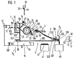
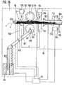
- An open-end spinning device 1 is usually part of an open-end spinning machine 16, which has a plurality of similar open-end spinning devices 1 arranged next to one another on one or both longitudinal sides of the machine.
- Each open-end spinning device 1 has a spinning element which, in the embodiment shown, is designed, for example, as a spinning rotor 10.
- the spinning rotor 10 is mounted in a known manner by means of a shaft 100 and is driven in the exemplary embodiment shown by means of a tangential belt 101.
- the spinning rotor 10 is arranged in a rotor housing 102, the interior 103 of which is connected via a suction pipe connection 104 to a vacuum source, not shown.
- a brake 11 can be delivered to the shaft 100 of the spinning rotor, which brake is connected to an actuating lever 13 via a linkage 12 which is only indicated schematically. If the free arm of the actuating lever 13 is acted upon in the direction of the arrow P4, the brake 11 comes to rest against the shaft 100 of the spinning rotor 10, so that the latter is braked.
- the mechanism, which consists of the brake 11, linkage 12 and actuating lever 13, is suitably acted upon by an elastic element against the direction of the arrow P4, that is to say in the direction of the arrow P5, so that when an application is ended in the direction the arrow P4 the brake 11 returns to its release position.
- Figure 1 is the elastic element, which acts on the mechanism consisting of brake 11, linkage 12 and actuating lever 13, designed as a compression spring 130, which is supported on the actuating lever 13 on the arm facing the linkage 12 and on a machine part, not shown.
- a feed device 2 which, in the exemplary embodiment shown, consists of a delivery roller 20 and a feed trough 21 which is pivotably mounted and is elastically pressed against the delivery roller 20 by a compression spring 22.
- Downstream of the delivery roller 20 is a dissolving roller 24 arranged in a housing 23, which during normal production combs fibers (not shown) from a sliver 4 fed to it with the aid of the feed device 2 from a can 41, which fibers pass through a housing 23 in the fiber feed channel 25 extending the spinning rotor 10 are fed to the spinning rotor 10.
- the fibers are deposited in the usual way on a fiber collection point in the spinning rotor 10, from where they are taken up by the end of a thread 44 and continuously bound into the end thereof.
- the thread 44 is drawn off through a thread draw-off tube 26 with the aid of a pair of draw-off rollers 27 and wound onto a bobbin 28 which is driven in a known manner by a bobbin roller 29.
- a thread monitor 14 which monitors the spun thread 44.
- the open-end spinning device 1 is covered by a cover 105, which has a feed hopper 106, and is supported by a machine frame 107.
- a signal device 15 is attached to the cover 105, e.g. in the form of a signal lamp which is connected in terms of control to the thread monitor 14 (usually with the interposition of a control device, not shown).
- a belt feeder 3 is fastened to the machine frame 107 below the rotor housing 102. In the embodiment shown, this is done with the aid of a guide 30, in which the belt feeder 3 is slidably mounted transversely to the machine longitudinal direction.
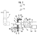
- the belt feeder 3 has a rail or guide rod 300 which extends through the guide 30 and carries a stop 301 at its machine-side end. At its end facing away from the stop 301, the guide rod 300 carries a band holder 31 which, according to FIG. 2, has two band holders 32 and 33 arranged at a distance from one another.
- the tape holder 32 is designed as a helical tape guide and has a slot 322 between its coils 320 and 321, which extends radially outwards from the guide area for the fiber tape 4 enclosed by the coils 320 and 321.
- the last-mentioned band holder 33 is located at a lateral distance a, which has a size which allows the sliver 4 delivered in a can 40 to be received between the band holders 32 and 33.
- this is a clamp formed and consists of a clamping element 330 firmly connected to the guide rod 300 and a second clamping element 331 which is movably arranged for this purpose.
- the clamping element 331 is acted upon by a compression spring 332, which in turn is supported on a spring receptacle 333 which is carried by the guide rod 300.
- the clamping element 331 is thus held elastically in contact with the clamping element 330.
- the free ends 334 and 335 of the clamping elements 330 and 331 are designed such that they move further and further apart from one another towards their free end. These two ends 334 and 335 thus form an insertion guide, which tapers in the transverse direction of the band course between the two band holders 32 and 33 and thus enables the automatic threading of the fiber band 4 in the direction of arrow P3 (see FIG. 1).
- the belt feeder 3 is - as FIG. 1 clearly shows - so high above the can 41 that the sliver 4 extending from the receiving position, which is below the feed device 2, but above the can 40, to the open-end spinning device 1, via others Cans 41 is guided away and can not come into contact with the sliver 42 which is located in the can 41 placed between the feeding device 2 and the can 4 and which usually extends to above the upper edge of the can 41.
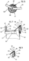
- a tape feeder 5 is provided to accommodate the sliver 3 extending between the two sliver holders 32 and 33.
- this consists of a controllable clamp in the form of a pair of overhung rollers 50, 51, of which the roller 50 can be driven by a motor 500 with the interposition of a clutch 501 the roller 51 is designed as a loose roller, which is driven by the driven roller 50, in operation via the sliver 4 inserted into the pair of rollers.
- This roller 51 which is designed as a loose roller, can be removed from the roller 50 by pivoting, so that a wedge-shaped gap 52 is formed between the two rollers 50 and 51.
- the pivot mechanism for the roller 51 has not been shown in FIGS. 1 and 2.
- the belt feeder 5 is also pivotally mounted as a whole on a rod 53 (see pivot point 530 in FIG. 2).
- An arm 54 extends laterally from the belt feeder 5 and is connected in an articulated manner to the armature 540 of an electromagnet 541.
- a new can 40 While the spinning station is still operating normally, a new can 40 must already be provided and the sliver 4 must be inserted into the sliver feeder 3 so that when the old sliver runs out, a new sliver is already ready to be taken up by the sliver feeder 5 and to be presented and handed over to the open end.
- Spinning device 1 is provided.
- the new sliver 4 is removed from the can 40, which is essentially placed under the sliver 3, and inserted with its beginning (beginning of the sliver 43 - FIG. 2) into the sliver holder 33 above the can, which is done automatically or by hand - Can be done by a simple movement in the direction of arrow P3 (Fig. 1).
- Ends 334 and 335 of the two clamping elements 330 and 331 form a conical insertion slot (or an insertion guide), and moreover in that, contrary to the action of the compression spring 332, the elastically mounted clamping element 331 moves so far from the other clamping element 330 that the beginning of the tape 43 of the sliver 4 is held securely near its free end between the two clamping elements 330 and 331.
- the sliver 4 By moving the sliver 4 in the direction of arrow P 1 (see Figure 2), the sliver 4 is inserted into the sliver holder 32, in which the sliver 4 is axially movable.
- the thread monitor 14 If the old sliver 4 now runs out, the thread monitor 14 is actuated since the thread 44 breaks in the absence of the sliver 4. The thread monitor 14 sends a signal to the signal device 15 of the open-end spinning device 1 in the usual way.
- the tape feeder 5, which is initially in a rest position 5 ', is caused by this signal to move from the rest position 5' (see FIG. 1) transversely to the sliver 4 in the take-up position into the tape take-up position (FIG. 2) .
- the roller 51 is moved against the roller 50, so that the sliver 4 is clamped between the two rollers 50 and 51.
- the sliver 4 can remain in the sliver holder 32 for any length of time, namely until it is unthreaded - automatically or by hand - at any time, for example when a new sliver is to be inserted into the sliver feeder 3, since its axial mobility results from the tape holder 32 is not affected.
- the feed device 2 is driven in coordination with the displacement movement of the belt feeder 5 or in coordination with the drive of the roller 50 of the belt feeder 5.
- the motor 500, the clutch 501 and the electromagnet 541 are in one common control device 93 is connected (FIG. 14), with which the drive of the feed device 2 is connected, possibly with the interposition of a machine-side control device 18 (see FIG. 18).
- a single drive 200 is provided for the delivery roller 20, which is controlled by the control device 93 and / or 18 (FIG. 18).
- the synchronization of the tape application and the switching on of the feed device 2 can take place in various ways.
- the control device 93 which controls this movement, generate a control pulse for switching on the individual drive 200 of the delivery roller 20.
- the delivery roller 20 is thus driven, which consequently grasp the fiber sliver 4 fed to it by the belt feeder 5 and can feed the opening roller 24 to dissolve it into individual fibers.
- the feed device 2 is only switched on in order to be able to take up the sliver 4 that has been put on. It is also important that there is no excess tape between the rollers 50, 51 of the belt feeder 5 and the feed device 2.
- the tape feed speed is therefore matched to the tape feed speed via the control devices 18 and 93.
- the swiveling speed with which the belt feeder 5 approaches the feeding device 2 is adapted to the peripheral speed of the delivery roller 20 and thus to the feeding speed of the feeding device 2.
- a switching flag 202 is arranged on the delivery roller axis 201 of the delivery roller 20, which is driven by a single drive 200, and is scanned by a light barrier 203 (see light source 204 and photo cell 205).
- Corresponding commands are then delivered to the control device 93 via a line.
- the control device 93 controls the speed at which the belt feeder 5 approaches the feed device 2 and feeds the sliver 4 into the feed device 2 in accordance with this pulse sequence predetermined by the delivery device 2.
- This speed of the belt feeder 5 is either the same as or even slightly less than the peripheral speed of the delivery roller 20, so that a loop formation in the supplied sliver 4 is avoided with certainty.
- the belt feeder 5 is brought up to the feed device 2 at any speed.
- the belt feeder 5 is then stopped and the motor 500 of the roller 50 is switched on.
- This motor 500 is now matched to the speed of the feed device in such a way that the roller 50 either has the same peripheral speed as the delivery roller 20, or else the roller 50 is driven at a somewhat lower peripheral speed, so that the sliver 4 between the rollers 50, 51 and the feeder 2 is slightly warped.
- the belt feeder 5 After the sliver 4 has been introduced into the feed device 2 - which, depending on the training, can normally be assumed after a certain time or what at the end the pivoting movement of the belt feeder 5 should be the case - the belt feeder 5 is controlled so that it releases the sliver 4 and can return to its basic position. The pair of rollers consisting of rollers 50, 51 is stopped. This completes the tape application process.
- a thread break was produced by the sliver 4 previously fed to the feed device 2.
- This re-spinning is carried out in the usual way by cleaning the spinning element, returning a thread end suitable for spinning up to the fiber collecting surface of the spinning rotor 10 or other spinning element, fibers being supplied to the fiber collecting surface by switching on the feed device 2 by appropriate time control Tie the end of the thread, which is then drawn off again by the spool 28 and later by the pair of draw rollers 27 from the spinning rotor 10 or other spinning elements (eg friction spinning elements).
- piecing methods that can be used in connection with the method and the device according to the invention, for which reason a detailed description of piecing is not given.
- the spinning rotor 10 is braked during the initial feeding of the sliver 4 to the opening roller 24 by acting on the actuating lever 13 in the direction of arrow P4 for the reasons described. Due to the negative pressure acting in the rotor housing 102 through the intake manifold connection 104, the fibers fed through the fiber feed channel 25 into the spinning rotor 10 are thus removed again from the rotor housing 102, so that the fibers in the spinning rotor 10 cannot form a fiber ring.
- the piecing is prepared, which - as mentioned - is carried out in the usual way.
- the feed device 2 is shut down for a predetermined time and only then put into operation again, so that a fiber ring is formed in the spinning rotor 10.
- a start of the thread 44 which has been retrieved from the spool 28 and prepared for spinning, is placed on this fiber ring and connected to the fiber ring, whereupon the withdrawal of the thread 44 starts again in a known manner.
- the fibers not only get the opportunity to get into the spinning rotor 10, but are already sucked off at the circumference of the opening roller 24 until the beginning of the thread 44 has been returned to the spinning rotor 10 on its fiber collecting surface. The removal of the fibers is then stopped and the fiber stream is fed back into the spinning rotor 10 so that it can connect to the thread 44 already located there, which is then drawn off in the usual way.
- a prerequisite for a piecing process to be able to be carried out in the case of an open-end spinning device 1 is that the tape application process has been carried out successfully.
- a tape monitoring device 520 is provided according to FIG. 14.
- this is essentially formed from the roller 50 and a sensor 503 and is thus arranged on the belt feeder 5.
- the roller 50 has markings 502, which are scanned by the sensor 503 of a scanning device.
- the markings 502 on the roller 50 are arranged very closely next to one another in the exemplary embodiment shown, in that the markings 502 have a maximum angular distance of 90 °, but if possible - depending on the roller diameter - considerably less.
- the sensor 503 is connected to the belt feeder 5 or its control device 93, to which the motor 500 of the roller 50 and the electromagnet 541 for the roller 51 are also connected.
- a signal lamp 94 is also connected to the control device 93.
- the roller 50 is not driven, in contrast to the state described above, since the sliver 4 is not transported, so that the sensor 503 cannot deliver any pulses to the control device 93.
- the control device 93 now causes the signal lamp 94 to light up, so that the operator can initiate the tape application process again.
- the tape application process can, of course, also be initiated automatically, the signal lamp 94 only lighting up if the tape application has not been successfully completed even after several attempts.
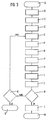
- failed attempts count program step N
- FIG. 20 shows a part of a perspective view modified design of a belt feeder 5 with the roller 50 driven by a motor (not shown in FIG. 20) and the roller 51, which is designed as a loose roller.
- the aforementioned wedge-shaped gap 52 is formed between the overhung rollers 50 and 51.
- the two rollers 50 and 51 are mounted in a housing 504, the side 505 of which faces the rollers 50 and 51 serves as a belt support and thus prevents that the sliver 4, especially when it is fed to the feeding device 2, can slip out of the pair of rollers 50, 51.
- the two rollers 50, 51 are provided with a thread-like corrugation or profiling 506 and 511, which is helical.
- the profiles are inclined to the surface lines of the rollers 50, 51 that they approach each other when the rollers 50, 51 rotate in the feed direction, ie in the direction of the beginning of the strip 43.
- the corrugation or profiling 506 and 511 can also take over the task of the markings 502 shown in FIG.
- the roller 51 When driving the roller 50 in the direction of arrow P19, the roller 51 is driven via the sliver 4 in the direction of the arrow P20, with a force being exerted on the sliver 4 in the direction of the arrow P21, through which the sliver 4 in the direction of the Gap 52 delimiting side 505 of the housing 504 forming a band support is moved.
- the band support can also be designed in another suitable manner.
- the receiving position for the fiber sliver 4 is determined by the sliver holders 32 and 33 in the working position.
- the two strap holders 32 and 33 are essentially on the same horizontal Level arranged.
- the two tape holders 32 and 33 can also be arranged one above the other, whereby in principle nothing essential changes for the tape take-up by the tape feeder 5.
- the belt feeder 5, which can possibly also be formed by the pair of rollers 50, 51 shown, then only has to be rotated by 90 ° in comparison to the embodiment shown in FIG. 1 for the reception of the fiber sliver 4.
- the sliver holder 33 is designed as a clamp in the previously described embodiment. However, this is not absolutely a requirement. So the tape retention can also by other means such. B. suction air or a Velcro can be achieved. Both strap holders 32 and 33 can also be designed as restraining means. A solution in which both strap holders 32 and 33 are designed both as a guide that allows axial movement and as a clamp that prevents them from slipping out of the strap holder 32 and 33 is also possible.
- the sliver 3 is slidably attached to the open-end spinning machine 16. If the belt feeders 3 protruding laterally from the open-end spinning machine do not interfere, they can also be rigidly attached to the machine frame 107.
- the belt feeder 3 is a separate device, but it is also possible to provide the receiving position in or on the can 40, etc., ie to provide the can 40 as a belt feeder 3 and / or train and that Submit sliver 4 through the can 40 of the open-end spinning device 1 or other textile machine for reception by the sliver feeder 5.
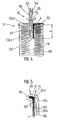
- FIG. 4 A first embodiment of this type is explained with the aid of FIG. 4. As this figure shows, is in the middle of the can 400, i. in the center of the sliver 4 deposited in the can 40, a space into which the beginning of the sliver 43 protrudes.
- a length b of at least 100 mm and a maximum of 200 mm has been found for this turned out to be particularly advantageous. If the strap end is shorter than 100 mm, there is a risk that the strap end will be pulled out of the can center 400.
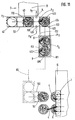
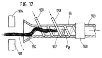
- a belt feeder 55 is also provided, which, in contrast to the belt feeder 5 shown in FIGS. 1 and 2, is of pneumatic design.
- This belt feeder 55 consists essentially of a base body in the form of a tube 550, which is closed by a wall 551 at its front end which can be brought into the center of the can 400.
- the tube wall is designed as a sieve 552 on a surface that extends along a producer line over part of the circumference of the tube 550.
- the tube 550 is connected at its end, not shown, to a vacuum source, so that in Area of the sieve 552, a suction air flow flowing into the tube 550 can be generated. If the band feeder 55 is now inserted into the can center 400 and rotated about its longitudinal axis (see arrow P Pfeil), the sieve 552 arrives in the region of the band end forming the later band start 43 and holds it there.
- the belt feeder 55 can now be moved vertically upwards out of the can center 400. He takes the end of the tape with him.
- the belt feeder 55 is now brought in front of the feed hopper 106 of the open-end spinning device 1 (FIG. 1), and the end of the belt which now forms the beginning of the belt 43 is moved by a suitable movement of the belt feeder 55 into this feed hopper 106 into the clamping area between the delivery roller 20 and the feed trough 21 introduced so that the feed device 2 can take up the sliver 4 and transport it further.
- the band feeder 55 is not moved to the extreme end of the sliver 4 during the insertion movement into the can 400, so that after the sliver 4 has been taken up by the Ribbon feeder 55 extends a predetermined ribbon length beyond the end of ribbon feeder 55. This free end of the sliver 4 can then be inserted into the feed device 2 by a movement through 180 °.
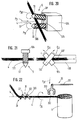
- the screen 552 is divided into two sub-screens 552a and 552b by an intermediate wall which merges into a longitudinal wall 553 of the essentially tubular belt feeder 55.
- two chambers 554 and 555 are formed in the belt feeder 55, each of which is optionally connected to a not shown by switching valves (not shown) Vacuum or can be connected to an overpressure source.
- both the chamber 554 and the chamber 555 are subjected to negative pressure.
- the belt feeder 55 is then brought into the correct position for the transfer of the sliver 4 to the feed device 2, which can be done both by rotating in the direction of the arrow P6 about its longitudinal axis and by pivoting through 180 °. If the belt feeder 55 is then in front of the feed hopper 106 (see FIG. 5), the chamber 554 is first subjected to excess pressure, so that the beginning of the belt 43 is blown into the feed hopper 106.
- the belt feeder 55 is then raised in the direction of the arrow P7 until the partial screen 552b also reaches the area in front of the feed hopper 106.
- the second chamber 555 is now also subjected to excess pressure, so that the fiber sliver 4 can further enter the feed hopper 106 and the feed device 2. Since the switching of the air conditions in the chambers 554 and 555 has to take place as a function of the position of the belt feeder 55 relative to the feed device 2, it is advantageous if this changeover takes place as a function of the movement or position of the belt feeder 55, but one is Time control for this purpose is also conceivable.
- the screen 552 can also have more than only two sub-screens 552a and 552b and correspondingly more than only two chambers 554 and 555, which are then also individually controlled, as explained below using the example of a tape dispenser with the aid of FIG. 9 becomes.
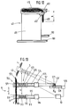
- FIG. 6 shows an alternative solution, in which the band end 430 extends outward beyond the can rim 401 and hangs outside the can 40, and here, as in the exemplary embodiment described above, the downwardly projecting band end should have a length that is between 100 mm and Is 200 mm.
- a belt feeder 56 which is designed essentially in the same way as the belt feeder 55 shown in FIG. 4, can be used.
- the belt feeder 56 is attached to the free end of a swivel arm 560, which can be rotated about a swivel axis 561.
- the pivot axis 561 is located at the end of a support arm 562, which can be placed with its pivot axis 561 in the center of the can 40 for receiving the band end 430.
- the belt feeder 56 is connected via lines (not shown) to corresponding sources of negative pressure or positive pressure, so that corresponding suction or compressed air flows can be generated in the belt feeder 56.
- the support arm 562 is mounted in a suitable manner on the open-end spinning machine 16, expediently with the aid of a device which can be moved along the machine and is thus enabled to operate more than just one open-end spinning device 1.
- the swivel arm 560 with the band feeder 56 is brought into the position shown in FIG. 6, in which the swivel axis 561 is located essentially centrally over the can 40. Now the swivel arm 560 is pivoted by at least 360 ° along the can rim 401, so that the belt feeder 56 surely passes the belt end 430 and takes it up in a defined manner due to the suction air draft prevailing in it.
- this belt feeder 56 works in the same way Way like that belt feeder 55, which is described with the aid of FIGS. 4 and 5.
- a different arm instead of a swivel arm 560 if the can 40 is given a rotary movement instead of the arm. All that is essential is the relative movement between the sliver 4 and the sliver feeder 56, so that the sliver 4 reaches the area of the sliver feeder 56 and can be picked up by the latter.
- the mechanical and pneumatic design, as described above, are merely exemplary embodiments. Other designs for taking up the sliver by adhesion due to icing or by electrostatic charging are also possible.
- FIG. 7 shows such an exemplary embodiment in which the belt feeder 3 has a belt holder 310 which is detachably fastened to the can 40.
- the band holder 310 in this case has a ring 311 which is fastened to the outer circumference of the can 40 with the aid of a snap closure 312. At several, at least two points on the circumference, the ring 311 has upwardly projecting bearings 313 which carry a resilient clamping element 314.
- the bearings 313 have an arm 316 with respect to the pivot axis 315 for the clamping element 314 on their side facing away from the ring 311, on which arm a compression spring 317 is supported.
- the Compression spring 317 is still supported on an arm 318 of the clamping element 314.
- the arm 316 of one of the bearings 313 ends in a band holder 323 designed as a band guide, which in the embodiment shown is open in the form of a "U" on the side facing away from the bearing 313 and forms a band feeder 3.
- the sliver 4 is inserted into this sliver holder 323.
- the band holder 324 has been modified somewhat compared to the band holder 323 of FIG. 7 in the receiving position on the relevant feed device 2.
- a further lever 325 is arranged on the pivot axis 315, on which the compression spring 317 is supported instead of the arm 316 of the bearing 313. In this way, the lever 325 forms an elastic clamp together with the arm 316.
- the strap end 430 hangs down from the strap holder 323 or 324 and can be picked up by a strap feeder in the manner shown in FIGS Transfer of the sliver 4 to the feed device 2.
- the device according to FIGS. 7 and 8 is particularly suitable for the manual insertion of the fiber sliver 4 into the sliver holder 323 or 324, since the ring 311 can generally only be placed on the can 40 after this can 40 has covered the distance 7 ( see Fig. 11) at which it was filled.
- the end of the band 430 which forms the beginning of the band in further operations, can be brought into its ready position or into its receiving position by inserting it into the band holder 323 or 324.
- the sliver 4 then remains inserted in this band holder 323 or 324 for the transport and possibly for further steps such as preparing the band application or the band application itself.
- the tape feeder 3 fastened to the machine frame 107 according to FIG. 1 can be constructed in a similar manner to the tape feeder 3 shown in FIGS. 7 and 8 and likewise have only a single tape holder 323 and 324 instead of two tape holders 32 and 33.
- the sliver 3 is arranged at a vertical distance above the upper can edge 401, so that the sliver 4 is sufficiently high above other cans 41 (see FIG. 1) to the feeding device 2 can be brought.
- FIGS. 23 to 25 show a further modification of a device in which the band end 430 is introduced into a holder when it is brought into the receiving position, in which the fiber band 4 remains inserted during further steps of the band application.
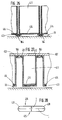
- Figure 23 shows a flat jug 411 in side view. Such a pitcher design will be discussed in more detail in connection with FIG. 12.
- the can 411 is shown to better show the arrangement to the right of its operating position below a delivery device 2 of the spinning machine.
- This delivery device 2 comprises a conventional delivery roller 20 and has a recess 206 for receiving a novel trough lever 210, which is now attached to the can 411 by a rod 319.
- the trough lever 210 engages in the recess 206, so that a belt end 430 held by the trough lever 210 is brought into interaction with the delivery roller 20.
- the sliver 4 is pulled out of the can 411 and introduced into the spinning station.
- FIG. 25 shows three such open-end spinning devices 1, each with a delivery device 2 and a can 411 associated with this spinning device 1, together with its rod 319.
- the cans 411 are in their operating position by guides 164 and 165 in the vicinity of the upper and / or lower end of the Can 411 led.
- FIGS. 26 and 27 each show a variant for the formation of guides for a can 40, 41 or 411.
- the can stands on rails 164 which are fastened to the bottom 19 below the open-end spinning devices 1.
- Additional guides 165 can be provided for the side walls of the can, as has already been shown in FIGS. 23 and 25.
- the can 411 is above the bottom 19 of rail-like guides 166 in the machine frame 107 worn.
- each can 411 is provided on the upper edge with a ledge 412 protruding outwards, which slides on the guides 166.
- the can walls have inwardly projecting edges 413 at the lower edge, which carry a loose can bottom 414 in each can 411.
- the can bottom 414 can be moved relative to the can walls by means provided on the machine, not shown. H. by external action - the jug 411 itself is not provided with any means to cause the jug bottom 414 to move relative to the side walls.
- This arrangement is useful because the introduction of the sliver 4 into the open-end spinning devices 1 does not cause the sliver 4 to warp.
- the sliver 4 can therefore extend from the delivery device 2 to the can bottom 414, the sliver 4 being drawn into the open-end spinning device 1 by the delivery device 2, without causing any distortions (yarn number fluctuations).
- the loose can bottom 414 also enables the can 411 to be filled with ribbon loops according to a predetermined pattern.
- FIG. 9 shows an automatically operating device which enables the sliver 4 to be placed in a position required for later picking up.
- a tape feeder 61 which in principle is like the tape feeder 55 or 56 is formed and, like this one, has a divided screen 552 and several chambers 554, 555 and 556 which can be optionally and individually connected to a vacuum or an overpressure source, is now moved in the direction of arrow P8 under the turntable 6 and up to the outlet opening 60 brought into a position 61 ', whereby the sliver 61 detects the deflected sliver 4. This sliver 4 is then cut in the usual and therefore not shown manner between sliver 61 and turntable 6.
- the can 40 is now transferred with the end of the tape deposited in this way to the open-end spinning device 1 (FIG. 1) in the receiving position, where a new sliver 4 is to be made available and where the sliver 4 is previously made with the aid of FIGS. 4, 6, 7 or 8 is recorded for the transfer to the relevant feed device 2.
- both the ready position and the receiving position can be provided on the can 40, from which the sliver 4 to be fed to the feed device 2 is to be removed.
- this ready position or the receiving position can either be in the center of the can 40 or in its peripheral region be provided.
- the sliver 4 can be taken up by a (not shown) sliver receiver - which can in principle be designed like the described sliver 61 or sliver feeder 55 or 56 - and inserted into a sliver 3 located there (see FIG. 1) so that it is there can be picked up by a belt feeder 5, 55 or 56 and transferred to the feed device 2.
- the sliver can also take the sliver 4 directly, i.e. without the interposition of a separate tape feeder 3, to the tape feeder 5, 55 or 56, so that the tape pickup also takes over the function of a tape feeder in this case.
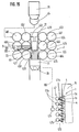
- FIG. 10 shows another device in which the movable separating web 620 of a belt separating device 62 is arranged in the rotating plate plate 600 receiving the rotating plate 6.
- a clamping fork 621 works together with the underside of the turntable plate 600 and with the separating web 620.
- the separating fork 621 is moved from the bottom upwards against the underside of the turntable plate 600, so that this separating fork 621 presses the sliver 4 against the underside of the turntable plate 600.
- the separating web 620 is now moved down between the two prongs 622 of the separating fork 621 and in doing so exerts an ever increasing pressure on the sliver 4 until it finally breaks.
- a switching flag 601 is provided at a suitable point on the turntable 6 and is scanned by a sensor 602, which is connected via lines 603 in a suitable manner to a control device (not shown).
- This control device acts on the drive of the turntable 6 and stops it when the turntable 6 is in the desired position for severing the sliver 4.
- the can 40 has been moved for the separation of the sliver 4 by a predetermined distance in such a way that the distance between the can edge 401 and the separating web 620 corresponds exactly to the length b by which the band end 430 is later to hang down on the can 40.
- the can 40 can be equipped with two lugs 402 (see also FIG. 12) which receive this band end 430 between them.
- a new can 410 has been pushed under the turntable 6 at the same time that the can 40 has been pushed out of the path 7.
- the defined positioning of the band end 430 on the can edge 401 can also be carried out in another suitable manner.
- the can 40 is moved out of the filling station after it has been filled at the filling station - which in the case of the section 7 described is formed by its delivery head 70 and the space below it - without the sliver 4 being fed in beforehand by the delivery head 70 is ended.
- the subsequent sliver 4 arrives on the trailing side of the can 40 and thus in a largely defined position.
- the sliver feed is stopped in such a way that the end 430 of the band protruding beyond the edge 401 of the can reaches the desired end Length b does not exceed.
- the sliver 4 is cut through in a suitable manner, for example as previously described in connection with FIG. 10, the sliver end 430 hanging outside the can 40 from the can edge 401 also has a length b within the desired tolerances.
- a device can be provided on the delivery head 70 or on the underside of the turntable plate 600, by means of which the sliver 4 is placed centrally with respect to the direction of extension of the can 40 and which, for example, in the form of two transverse to the can extension direction (see arrow P12 in Figure 11) movable band centering 74, 740 (see arrows P9 and P10) is formed.
- the band centerings 74, 740 are located on the delivery head 70 at a point between the outlet opening 60 of the turntable 6 and the can rim 401 of the can 40 after it has left the filling station.
- the two band centers 74 and 740 are at the same level as the sliver 4 on both sides of the sliver 4 extending from the delivery head 70 to the can 40 Ejection movement ended or at least almost ended, the band centerings 74, 740 are brought closer to one another, grasp the fiber band 4 and bring it to the center line of the can web between the filling station and the subsequent rest position of the can 40.
- the band end 430 comes to the center Extending direction (arrow P12) to lie on the trailing can side on the can rim 401.
- the can 40 has guides which hold this can 40 in the desired position relative to the path 7, ie to the turntable 6. This is explained below with reference to FIG. 11, which shows a line 7 with its delivery head 70, a vehicle (transport carriage 8) for transporting the can 40 from the line 7 to the open-end spinning device 1 and the open-end spinning machine 16 with a large number of open-end Spinning devices 1 shows.
- the can 40 does not lose its orientation from the delivery head 70 of the line 7 until the take-up position is reached by the start of the belt 43 in the vicinity of the open-end spinning device 1, the can 40 has a guide which is guided by guides on the line 7 and on the open-end Spinning machine 16 works together.
- the can 40 has a rectangular profile, the sides 403, 404, 405 and 406 of which serve as guides.
- the guides formed by the sides 403 and 405 work together with guides 700 and 701, between which the cans 40 are conveyed under the delivery head 70 and later out of their position under the delivery head 70. Pages 404 and 406 also serve as guides for cans 40 and cooperate with guides 702 and 703.
- the can 40 is presented to route 7 in the usual and therefore not shown manner. It is then filled in its position under the delivery head 70 (program step A, FIG. 3). After filling the can 40, it is ejected in the direction of the arrow P 12 from the path 7 and the band end 430 is brought into the desired position, ie into its ready position, from which it can later be resumed for the further operations (program step B). The tape end 430 is secured in this position, which by the two lugs 402 can happen (program step C). The can 40 is then pushed along the arrow P13 and possibly P14 on the trolley 8.
- the transport carriage 8 also has guides 81, 810, 811 and 812. The can 40 is thus secured against rotation during the entire transport duration and can therefore neither change its relative rotational position with respect to the route 7 nor with respect to the transport carriage 8 during its entire transport.
- the provision of the sliver 4 takes place in the manner described above, namely according to the exemplary embodiment shown in FIG. 10 between the lugs 402.
- the transport carriage 8 with the can 40 deposited thereon and possibly one or more further cans is now along the line 80 moved to the open-end spinning machine 16 in front of an open-end spinning device 1, where a new can 40 is required.
- Guides 160 and 161 are also provided there per open-end spinning device 1, so that the can 40 cooperating with these guides can be brought into its receiving position below the open-end spinning device 1 without changing its rotational position relative to the open-end spinning device 1 (program step D).
- the sliver is picked up and transferred to the open-end spinning device 1 in the manner described above (program steps E, H and I).
- the lugs 102 or the free end of the belt is not on the side of the can 40 facing away from the open-end spinning device 1, but rather on the side facing the open-end spinning device 1.
- This can be done by unloading the trolley 8 - in contrast to the embodiment according to FIG. 11 - not to the right but to the left and the cans 40 of open-end spinning devices located there 1 can be fed.
- a turntable (not shown) on the trolley 8 per can 40 so that the cans 40 can be brought into the desired rotational position by rotating these turntables, in which the sliver 4 can then be moved with the aid of a simple, not on a swivel arm 560 (see FIG. 6) arranged belt feeder 5 (FIG. 2) or 55 (FIG. 4) can be received.
- corresponding ejection brackets can be provided on the trolley 8, which can be controlled from the open-end spinning device 1.
- the transport carriage 8 is connected in a manner not shown to the open-end spinning device 1 or to the central control device (FIG. 18) of the open-end spinning machine 16.
- the guides for maintaining a defined position the cans 40 can be designed differently, as the exemplary embodiments described above show.
- the guides connected to the can 40 can be releasably attached to this can 40 or to the tape feeder 3 carried by the can 40 and, if desired, by correspondingly flat outer surfaces of the can 40 (see pages 403, 404, 405 and 406 of the figure) 18 can 40 shown) or the ring 311 (see Figure 7) are formed.
- the jug 411 does not have a round profile, but is elongated. Its two long sides can thus serve as a guide, with the help of which the can 411 is guided from the route 7 to the open-end spinning device 1 between two guides 700, 701 or 81, 810 or 160, 161 (see FIG. 11).
- lugs 402 can be provided on the can 411, between which the band end 430 is held, which - as described - projects with a length b over the edge of the can 411 and hangs down there.
- FIG. 29 shows a series of twenty-three spinning positions of an open-end spinning machine and a transport carriage 8 for transporting flat cans (cans 411) and for exchanging such cans 411 at the spinning positions.
- the trolley 8 comprises a can-receiving part 82 and two end parts 83, 84.
- the can-receiving part 82 is divided into compartments by partitions 820, each compartment being suitable for receiving a flat can (can 411) by moving the flat can in its longitudinal direction.
- Each end portion 83, 84 carries a post 830, and the posts in turn carry a bar 831, which serves as a guide rail for a can manipulator 85.
- the can manipulator 85 can be moved in the longitudinal direction of the bar 831 and can thereby be delivered to the individual compartments of the can-receiving part 82.
- the can manipulator 85 comprises its own rail 850, which is perpendicular to the beam 831 and serves as a guide rail for a can slide 851.
- the can slide 851 comprises a gripper (not shown) which, by moving in the direction of the central plane of the open-end spinning machine, pushes the can 411 taken from the transport carriage 8 into the operating position in the machine or by moving it away from the central plane of the machine 411 pulls from their operating position onto the transport carriage 8.
- a gripper not shown
- Each end part 83, 84 of the transport carriage 8 also has wheels 86 which enable the movement of the vehicle in directions perpendicular to the long side of the cans which have been received.
- the transport carriage 8 comprises a drive (not shown) and possibly a controller which controls a steering system (not shown) for the wheels 86.
- the trolley 8 is guided by a system control to a selected spinning station at which the can 411 is to be replaced.
- a suitable positioning system (not shown here)
- the transport carriage 8 is initially positioned such that the empty compartment is aligned with the spinning station (open-end spinning device 1), where the can 411 is to be exchanged.
- the can manipulator 85 is assigned to the empty compartment and the can pusher 851 is moved inwards relative to the machine so that its gripper (not shown) can be exchanged can 411.
- the can 411 to be replaced is pulled into the previously empty compartment of the transport carriage 8.
- the transport carriage 8 is then moved to align a compartment filled with a full can 411 with the relevant spinning station.
- the can manipulator 85 is moved along the bar 831 in order to deliver the can manipulator 85 to the newly introduced can 411. By moving the can manipulator 85 inwards (opposite the machine), this full can 411 is then moved into the operating position.
- the transport carriage 8 can now be delivered to another selected spinning station, where the procedure is repeated, the empty compartment on the transport carriage 8 now not being in the original position, but instead in the place of the full can 411 last delivered to the machine.
- the empty compartment is gradually moved until all full cans 411 have been inserted into the open spinning machine and replaced with empty (or at least to be replaced) cans 411.
- the trolley 8 is then moved back to route 7.
- the can-receiving part 82 of the transport carriage 8 need not be rigidly connected to the end parts 83, 84 of the transport carriage 8. As indicated in FIG. 29 by double arrows 821, the part 82 can also be height-adjustable relative to the end parts 83, 84 in order to bring the cans 411 at the same height from the part 82 into their loading or unloading position on the line 7 or the open-end spinning machine or another Textile machine or device - and of course also in the opposite direction - to be able to move. Similarly, too other elements such as B. the tape feeder 5, tape start preparation device 9 (which will be described below) height-adjustable on the trolley 8 stored.
- the flat can 411 shown in FIGS. 12 and 28 has two parallel side walls 415, 416 which define the can width i.
- the can 411 also has two end pieces 417, 418 which connect the side walls and define the can length j.
- rounded end pieces 417, 418 are shown, but these are instead perpendicular to the side walls 415, 416 or can be designed as polygons.
- the jug length j is significantly larger (e.g. three to four times larger) than the jug width i, which is essentially the width of a spinning station, i. H. corresponds to an open-end spinning device 1. In this way it is achieved that the capacity of the flat jug 411 corresponds to the capacity of a conventional round jug.
- the capacity of a flat jug 411 should correspond to the capacity of a round jug with a diameter of 450 to 500 mm. If it is assumed as an example that the diameter of a conventional round can is approximately 457 mm, then a flat can (can 411) according to FIG. 28 with a width of 230 mm and a length of 780 mm has a somewhat larger capacity than the round can. In other words, the length of the flat can does not have to be twice the round can diameter in order to give the same capacity.
- the height of the can is given by the construction of the spinning machine frame, since the cans 40, 41 or 411 have to be placed under the spinning station.
- the beginning of the band 43 (through the Band end 430 is formed) is not fed unchanged to the open-end spinning device 1, but is still especially prepared for transfer to the feed device 2. Due to external influences during the time from the insertion of the sliver 4 into the sliver holder 31 (FIG. 2) or 323 (FIG. 7) or 324 (FIG. 8) or also inside the can 40 (FIG. 4) or on the can rim 401 (FIG 6) namely the sliver 4 can be moved or pulled out of the can 40, 41 or 411, so that the state and / or the length of the sliver 4 changes.
- the beginning of the band 43, with which the sliver 4 is to be fed to the open-end spinning device 1 always has the same quality.
- the tape start 43 to be applied is brought to a defined length.
- a tape start preparation device 9, as shown in FIG. 13, is particularly useful for this.
- a controllable clamp 91 is assigned to the band holder 31 in the embodiment as shown in FIG. 2, or in the embodiment as shown in FIG. 13, or in another embodiment, which can in principle be designed differently.
- this clamp 91 is arranged stationary and has a carrier 910, at one end of which a stop 911 is arranged.
- an electromagnet 914 is arranged on the carrier 910 and is connected to a counter-stop 916 via an armature 915.
- This counter stop 916 can be brought into contact with the stop 911 or clamp a sliver 4 between it and the stop 911.
- the armature 915 is guided by a spring support 912, which in turn is supported by the carrier 910 between the counter-stop 916 and the armature 915 is provided.
- a compression spring 913 is supported at one end on the counter stop 916 and at the other end on the spring support 912. If the electromagnet 914 is de-energized, ie in the dropped state, the compression spring 913 acts on the counter stop 916, so that the sliver 4 is clamped between it and the stop 911. If, on the other hand, the electromagnet 914 is excited, the counter-stop 916 is removed from the stop 911 against the action of the compression spring 913, so that the sliver 4 is released.
- the clamp 91 works together with the belt feeder 5.
- a device serves as the belt feeder 5, which is designed essentially in the same way as the clamp 91.
- a clamp 512 is arranged at its free end, which has a stop 571 with which a counter-stop 573 acted upon by a compression spring 572 cooperates.
- the counter stop 573 is connected to the armature 574 of an electromagnet 575.
- the armature 574 is guided by a spring support 576, which also supports the compression spring 572 acting on the counter stop 573.
- a pinion 577 is mounted, with which a rack 578 which can be driven by a drive 579 cooperates and can be moved back and forth in the direction of the double arrow P 1.
- the rack 578 with its drive 579 thus forms a drive for changing the relative distance between the terminal 91 and the terminal 512 of the belt feeder 5.
- the two terminals can be controlled synchronously, at least with regard to the closing, in order to ensure the separation function.
- the sliver 4 is then inserted into the two clamps (which come from stop 571 and counter stop 573 existing terminal 512 and terminal 91) inserted. Then, by moving the rack 578 towards the stop 571, the clamp 512 of the belt feeder is pivoted so that it moves away from the clamp 91. The sliver 4, which is held in the clamps 91 and 512, is thus pulled apart until it breaks.
- a minimum distance c is provided between the shown starting position of the clamp 512 and the clamp 91, which is equal to the staple length (average staple length) of the fibers contained in the fiber band 4, that is to say is predetermined by the stack length of the fibers contained in the fiber band 4.
- a band start 43 is created in this way, which is particularly suitable for insertion into the feed device 2. Since the fiber ends are distributed fairly evenly in the sliver 4, the tearing of the sliver 4 causes thinning and tapering of the beginning 43 of the sliver, which is therefore particularly suitable for insertion into the feed funnel 106 (see FIG. 1).
- the two electromagnets 914 and 575 and the drive 579 of the rack 578 are common Control device 93 connected, which ensures that the movement of the clamps 512 and 91 of the tape start preparation device 9 takes place only after the counter stops 573 and 916 abut against the stops 571 and 911, respectively.
- a cutting device 34 As shown in Figure 2, it is also possible to cut the sliver 4, a cutting device 34, z. B. scissors or the like to be arranged on an arm 302 of the guide rod 300 of the sliver 3.
- This cutting device 34 simultaneously fulfills the task of a tape measuring device and can then be triggered manually or electrically in a manner not shown, if desired. If an electro-mechanical separation of the sliver 4 is not required, it may also be sufficient to provide only the arm 302 with a scale, not shown, for the dimension of the length of the sliver start 43, then shortening the sliver 4 using a simple one , can be done, for example, by hand in the place of the cutting device 34 shown in FIG. 2.
- the cutting device 34 or the scale, not shown, thus forms a tape length measuring device which is attached to the tape feeder 3 and by means of which the length b of the tape start 43 desired for the tape application can be generated or checked. If the can 40 serves as a belt feeder 3, a marking on the circumference of the can may also be sufficient for this.
- the sliver can also be separated in other ways. This makes it possible to use an injector through which a medium is directed onto the fiber sliver 4 (medium pulse). If necessary, thermal burning of the fiber sliver is also possible, particularly in the case of natural fiber material, in which there is a risk the fusion of the fibers is less than with synthetic fibers.
- the separating device can be designed in various ways. Since a cutting device generates a rectangular profile of the band start 43, a device for pulling the fiber band 4 apart is particularly advantageous since it produces an essentially wedge-shaped band start 43. In the latter case, the tape cutting device is formed by the tape start preparation device 9.
- the sliver 4 can also be pulled apart by turning the rollers 50, 51 backwards with the sliver 4 clamped by the clamp 91; an additional terminal 92 is then not required.
- a tape length measuring device e.g. can be combined in the manner of a light barrier 962 (FIG. 15) which controls the rollers 50, 51 in such a way that the strip end 43 is located in the region of this light barrier 962.
- the clamp 91 cooperating with the ribbon feeder 5 is connected via the control device 93 to the drive (motor 500) of the roller 50 of the ribbon feeder 5 for control purposes.
- a monitoring device serving as a tape length measuring device can also be provided on the tape feeder 3, which monitors where the tape start 43 is located and then drives the rollers 50, 51 in one direction or the other until the tape end 43 is located at this monitoring point.
- the monitoring point can be formed by a light barrier which, if desired, can be adjusted along arm 302 in any desired position.
- a belt feeder 5 formed by a clamp 512 one which is shown in FIG. 2 and which has two rollers 50 and 51 can also be used.
- the tape feeder 5 is, as the above description shows, part of the tape start preparation device 9 and is movable relative to this. On the one hand, this is necessary in order to be able to pick up the sliver 4 in the receiving position and to be able to feed it to the feed device 2. On the other hand, this mobility is expedient in order to bring the sliver 4 to the desired length by pulling it apart.
- the other part of the tape start preparation device 9 can also be movably mounted, this mobility can be dispensed with in view of the mobility of the tape feeder 5. For this reason, in the exemplary embodiment shown in FIG. 13, the part of the tape start preparation device 9 which cooperates with the tape feeder 5 is stationary and the tape feeder 5 can be delivered to this stationary part.
- the relative mobility between the parts of the tape start preparation device 9 does not have to take place by pivoting one or both of its cooperating parts.
- Other movements e.g. Thrust movements, rotary movements etc. are naturally also conceivable.
- FIG. 15 shows a further modification of the device described, in which the belt feeder 5 is brought with its rollers 50, 51 in front of the mouth 950 of a suction pipe 95 can.
- the free strip end 430 is thinned and shortened by the suction draft prevailing in the suction pipe 95 or in the suction nozzle of the strip start preparation device 9, which can of course be switched on and off.
- the suction train acting in the suction pipe 95 thus forms a pneumatic belt cutting device.
- the belt feeder 5 is stopped at a minimum distance c in front of the mouth 950 that it essentially corresponds to the average stack length of the fibers contained in the fiber band 4. Since all the fibers outside this area, which is defined by the minimum distance c, are no longer held by the rollers 50 and 51, they can be pulled out of the fiber sliver 4 and removed with a correspondingly strong and possibly turbulent air flow.
- a cutting device 96 is additionally provided in the suction pipe 95 according to FIG.
- This cutting device 96 has a knife 960 which, from a rest position in which it releases the interior of the suction pipe 95, can be moved transversely to the longitudinal course of the suction pipe 950 and cooperates with an anvil 961.
- the anvil 961 is designed as a roller or cylinder according to FIG. 15 and rotatably mounted about its axis.
- the knife 960 is guided in the suction pipe 95 in a guide 951 and can therefore not perform any lateral movement apart from the stroke movement given to it.
- the anvil 961 designed as a roller is elastically supported.
- the knife 960 rotates the roller-like anvil 961 according to its predetermined stroke in each case by an angle of rotation ⁇ predetermined by the knife stroke.
- the knife 960 cooperates with a different location on the roller-like anvil 961.
- the anvil 961 is made of soft material in relation to the knife 960 and is therefore subject to greater wear. Due to the possibility of rotation (with each stroke by the angle of rotation ⁇ ), another circumferential location of the anvil 961 reaches the working area of the knife 960, so that non-uniform wear of the anvil 961 is avoided.
- the sliver 4 is inserted into the suction tube 95 so far that the end of the band 430 is passed between the knife 960 and the anvil 961 with certainty.
- This can optionally be monitored by a length scanner (e.g. a light barrier 962) between a light source 963 and a photodiode 964.
- This light barrier 962 is in control connection with the rollers 50 and 51 and the knife 960 via the control device 93 (see FIG. 14) and signals to these elements that the sliver 4 is in the correct position.
- the rollers 50, 51 are stopped; the knife 960 is actuated and cuts the tape end 430. This is removed due to the prevailing suction draft. Due to the still prevailing negative pressure in the suction pipe 95, the remaining end of the strip is also exposed to the suction draft and thinned and thereby sharpened.
- the thinned, new end of the tape is in principle optimally prepared for insertion into the feed device 2.
- a nozzle 965 serving as a band end fixing device is provided for this purpose, which nozzle can spray a liquid suitable for solidification onto the beginning of the band 43.
- the condition of the sliver 4 in the area of the beginning of the sliver 43 should deviate as little as possible from the normal sliver condition, i.e. if possible have only a pointed shape, but otherwise correspond to the normal sliver 4.
- a medium which evaporates without residue after a short time is particularly cheap, the time naturally being sufficient for the introduction of the band beginning 43 into the feed device 2.
- the band beginning 430 can be iced up with a medium which consists of the solid Physical state changes directly into the gaseous state.
- the nozzle 965 is designed as an icing device which, when an, for example, gaseous medium escapes, causes it to change to the solid state by icing and later - as mentioned - to return directly to the gaseous state.
- the band end fixing device need not be designed as a spray device.
- Other devices with which a fixing medium in the solid (or semi-solid), liquid or gaseous state can be applied to the band start 43 are also suitable for this purpose.
- the tape feeder 5 together with the suction pipe 95 already forms a tape start preparation device 9 on its own, but also in combination with the cutting device 96. As described, this causes the tape end held back by the tape feeder 5 acting suction air flow an opening and partial dissolution of the tape end and thus a tapering or tapering the same.
- the preparation of the tape start in this embodiment is thus pneumatic and not by the movement of two elements of the tape start preparation device 9 or by turning the rollers 50, 51 of the tape feeder 5 backwards. No cutting device 96 is required for preparing the tape catch 43, even if such is shown in Figure 15.
- FIG. 16 shows a further embodiment of the subject matter of the invention, in which the two parts of the tape start preparation device 9 can also change their position relative to one another. Naturally, this can be done by moving the tape feeder 5 or by moving another part of the tape start preparation device 9 relative to the tape feeder 5 or also by a simultaneous movement of both the tape feeder 5 and another part 99 of the tape start preparation device 9.
- the two rollers 50 and 51 - upstream of the strip 43 - are preceded by a clamp 92, which consists of a stationary clamping part 920 and a movable clamping part 922.
- the two clamping parts 920 and 922 have interlocking profiles in the embodiment shown. According to FIG. 16, this is achieved in that the clamping part 920 has a concave clamping surface 921 and the clamping part 922 has a convex clamping surface 923.
- these clamping surfaces 921 and 923 are provided with rounded profiles in order to ensure that the sliver 4 is retained gently.
- a clamp 91 is also arranged in front of the suction pipe 95, which is designed, for example, in the manner of the clamp shown in FIG. 13 and has a stationary clamping part (stop 911) and a movable clamping part (counter stop 916).
- the two clamps 91 and 92 are controlled synchronously, at least for their closing movement, to ensure that when these two clamps 91 and 92 are moved apart, the sliver 4 is actually pulled apart.
- the two clamps 91 and 92 are initially in a starting position, after the fiber sliver 4 has been introduced into the suction pipe 95 with the assistance of the negative pressure switched on, in which the two Clamps 91, 92 have a minimum distance c in the order of an average length of the staple fibers.
- the fiber sliver 4 is then severed by moving the two clamps 91 and 92 apart. If this has happened, the roller 51, which was initially lifted from the roller 50 for the tearing apart of the fiber sliver 4, is returned to its clamping position, wherein the fiber sliver 4 is clamped between it and the roller 50. Now the belt feeder 5 is again approached to the clamp 91 and the beginning of the belt 43 is inserted into the suction pipe 95.
- the suction pipe 95 has an opening in the form of an insertion funnel 952.
- the negative pressure in the suction pipe 95 which can optionally be switched off for the duration of the tearing apart of the sliver 4 and then switched on during the renewed insertion of the sliver 4 into the suction pipe 95, now pulls fibers out of the beginning of the band 43 and thus gives the beginning of the band 43 tapered shape.
- the clamp 91 need not be arranged in front of the mouth of the suction pipe 95. If desired, the clamp 91 can also be arranged in the intake manifold, e.g. B. at the point at which the cutting device 96 is provided according to FIG. Also in this case, the fiber sliver 4 can be torn apart by moving the sliver feeder 5 and the clamp 91, so that a sliver start 43 of a defined length is produced.
- the suction pipe 95 is rotatably supported, which is indicated by the arrow P17.
- a drive motor 953 is provided which carries on its drive axle 954 a pinion 955 which engages with another pinion 956 which is arranged concentrically on the intake manifold 95 and connected to it.
- the drive motor 953 is connected to the control device 93 in terms of control.
- the rotation of the suction pipe 95 rotates the beginning of the band 43, to which the rotation is transmitted due to its small inside diameter and / or due to the relative arrangement of the suction pipe 95 to the rollers 50 and 51, as a result of which the beginning of the band 43 is solidified in its shape.
- the suction pipe 95 is arranged with its axis g parallel, but laterally offset to the plane e.
- the sliver 4 should be in the separation area, i.e. between the two clamps 92 and 91 have their full strength, so that the strip end 43 generated is defined in its shape within acceptable tolerances.
- this check is carried out with the aid of a light barrier 962 in the intake manifold 95.
- a scanning device 97 is provided for determining the strip thickness.
- This sensing device 97 has a swivel arm 971 which is pivotably mounted about an axis 972 and has at one end a sensing roller 970 which scans the axis 510 of the roller 51.
- an armature 973 is connected to the swivel arm 971, which plunges into the interior of a coil 974.
- the coil 974 is connected to the control device 93, which is also in control connection with the electromagnets 575 and 914, the motor 500 for the roller 50 and the drive motor 953.
- the sliver feeder 5 is again approached to the suction pipe 95 and the beginning of the sliver 43 is inserted into the suction pipe 95, the funnel 952 facilitating such insertion. If desired, it can be provided that after the introduction of the belt start 43 into the funnel 952 of the suction tube 95, the roller 50 is driven and the sliver 4 is conveyed deeper into the suction tube 95.
- the motor 500 of the roller 50 is then stopped. Then the two electromagnets 575 and 914 are actuated, which now clamp the sliver 4. Then the belt feeder 5 removed from the terminal 91 or in some other suitable way increases the relative distance between the two terminals 91 and 92. Since the minimum distance c between the two clamps 92 and 91 corresponds at least to the average length of the fibers contained in the sliver 4, the sliver 4 can be separated in a simple manner by pulling apart. Due to the interlocking profiles of the clamping parts 920 and 922 of the clamp 92, the sliver 4 is held back gently by the sliver feeder 5.
- the roller 51 When the sliver 4 is inserted into the suction tube 95, the roller 51 changes its relative distance from the roller 50 in accordance with the thickness of the sliver. These movements of the roller 51 are transmitted to the armature 973 via the feeler roller 970, so that a corresponding current is induced in the coil 974 in accordance with these fluctuations in the thickness of the sliver 4, which current is passed on to the control device 93. This causes the roller 50 to be driven for as long after the belt feeder 5 has reached its working position relative to the suction tube 95 until the sliver 4 has reached its full strength and no significant fluctuations in the belt thickness due to the feeler roller 970 via the armature 973 and the spool 974 more can be registered in the control device 93.
- the sliver feeder 5 is again brought into its position shown in FIG. 16 in accordance with the exemplary embodiment shown in FIG. 16. in which the rollers 50, 51 have reached their next position in relation to the suction pipe 95.
- the roller 50 is now driven for a predetermined number of revolutions, so that a defined one Length is inserted into the suction pipe 95.
- the suction pipe 95 is now driven in the direction of arrow P17 and rotates the front end of the tape 43 so that it receives a tip. The tape tip later facilitates insertion into the feed device 2.
- the feeler device described also makes it possible to convey the sliver 4 to such an extent that a section of the belt which does not correspond to the desired thickness is removed in the subsequent separation process. This can be achieved regardless of where and how the feeler device is designed, for example with capacitive scanning of the sliver 4 and / or if a suitable feeler device is arranged independently of the belt feeder 5.
- a helical groove 957 is provided for this purpose in the suction pipe 95, into which compressed air nozzles 958 with an axial and a tangential component open at one or more points.
- the suction pipe 95 is connected via a valve 930 and a vacuum line 959 to a vacuum source, not shown.
- the beginning of the band is brought into a molding press (not shown).
- a molding press (not shown).
- inward-directed nozzles can then also be provided in this molding press, through which nozzles an icing agent or other hardening agent can be applied.
- FIG. 21 A further exemplary embodiment of a strip end preparation device 9 is shown in FIG. 21.
- the strip end preparation device 9 is completely mechanical.
- the tape start preparation device 9 has, in addition to the rollers 50, 51 of the tape feeder 5, another pair of rollers, the rollers 924 and 925 of which can both be driven in opposite directions by their own drive (not shown) (see arrows P22 and P23). Due to the limited arrangement of the two rollers 924 and 925, not only a tensile force is exerted on the sliver 4, which together with the clamping force exerted by the sliver feeder 5 causes the sliver 4 to be pulled apart. The band piece 407 separated in this way is additionally conveyed by the rollers 924 and 925 and placed on a conveyor belt 408, which now transports the band piece 407 to a collection point (not shown).
- the device for applying a sliver including the auxiliary devices described from fixing the sliver 4 at a defined point on the can 40 or another sliver 3 to inserting the sliver 4 into the feed device 2
- individual features can be replaced by equivalents and combined with one another in any way.
- the sliver 4 is brought into a receiving position in the vicinity of the feed device 2 to be operated.
- the beginning of the band 43 can also be tapered by tearing off a section of band and brought into an optimal shape for application by manual sharpening.
- FIG. 19 shows a system with a card 79, the loading device of which is not shown for the sake of clarity.
- the card 79 supplies a can 45 which, like other cans, is fed to a draw frame 7.
- six slivers 420 to 425, which are removed from cans 450 to 455, are fed to the stretching head of draw frame 7.
- the sliver is placed in the can 45 at the outlet of the card 79 in the manner described above and fixed there in a standby position.
- the can 45 is then also guided in the manner described - similar to that between the section 7 and the open-end machine 16 - in such a way that a belt feeder can find and grasp the end of the strip and insert it into the feed device 2, which is located in a section 7 in the stretching head 71 is located and 420 to 425 is provided once per sliver.
- the tape feeder 5, possibly also a tape start preparation device 9, are carried by a carriage 73 which is arranged and movable above the tape guide table 72 in a manner not shown.
- the tape feeder or the entire tape start preparation device 9 is movable in a manner not shown in such a way that it receives the slivers (not shown) from the outer row of cans 46, 460, 461, 462, 463 and 464 and can insert into the respective feed device in the stretching head 71.
- the feed device 2 is formed by the pair of inlet rollers of a drafting system.
- the slivers - six tapes in the exemplary embodiment shown - are duplicated and warped, the thickness of the sliver supplied corresponding to the thickness of the individual slivers 420 to 425 supplied.
- the cans have 47 such a dimension that they extend over two adjacent open-end spinning devices 1. For this reason, it is provided that a can 47a of a first row of cans is assigned to every second open-end spinning device 1a and a can 47b of a second row of cans to each intermediate open-end spinning device 1b.
- a can group 470 consisting of a can 47a and a can 47b
- the sliver 4 threatens to run out
- a corresponding impulse is given to the control device 18 of the open-end spinning machine 16, which then causes so soon as possible behind the two cans 47a and 47b in a third row a can 47c is already provided as a reserve can in a waiting position.
- the sliver 4 is then transferred from the can 47c into the corresponding feed device 2, which is stopped by the sliver 4, in the manner described above Open-end spinning device 1a or 1b of such a pair of spinning devices is introduced.
- FIG 18 shows a schematic representation of the essential elements for implementing the invention.
- the elements of the tape start preparation device 9, its clamps 91 and 92, and its control device 93, which have already been described above, and which are required for taking up and putting on the sliver 4, are located in this exemplary embodiment on a maintenance device 98 which runs along the open-end spinning machine 16 and its multitude of open-end spinning devices 1 can be moved.
- This can be a maintenance device, which, if desired, either only carries out the tape laying or which additional tasks takes over such. B. spool change, piecing, etc. If necessary, several different maintenance devices for one or more of the different special tasks can be provided on the machine.
- FIG. 18 also shows a drive device 58 for the belt feeder 5, this drive device being able to produce a wide variety of movements as required.
- FIG. 18 In front of the open-end spinning device 1, of which only the feeding device 2 is shown in FIG. 18, in this exemplary embodiment there is not only a single feed hopper 106, as shown for example in FIG. 1, but a rail 17, in which per spinning station two feed hoppers 170 and 171 are provided, which can be brought alternately into their work place directly in front of the feed device 2.
- these feed hoppers 170 and 171 have a toothed contour which has the purpose of preventing the sliver 4 from sliding back, or at least making it difficult.
- the pulling of the sliver 4 in the direction of the feed device 2 is not impaired by this configuration of the feed funnels 170 and 171.
- the two photodiodes 173 and 174 are in control connection with the control device 18 of the open-end spinning machine 16.
- Two control devices 177 and 178 are also in control connection with the control device 18, of which the drive device 177 of the rail 17 can give a longitudinal movement and the drive device 178 of the rail 17 can give a transverse movement.
- the open-end spinning device 1 is fed by the feed device 2 with a sliver 4 which is removed from a can 40.
- the sliver 4 is fed through the feed hopper 170 to the feed device 2.
- the light barrier 175 thus detects the presence of a sliver 4.
- the light barrier 176 detects the absence of a sliver 4 and sends a corresponding false signal to the control device 18.
- the control device 18 issues a corresponding command to the control device 93 of the maintenance device 98.
- the maintenance device 98 either called to this open-end spinning device 1, where a sliver 4 has run out, or stops the next time it passes this open-end spinning device 1.
- a sliver 4 previously provided in the sliver holder 32 is then taken up in the manner described above by the sliver feeder 5 and brought into the desired state in the sliver start preparation device 9. This has been indicated by the dashed line 59.
- the tape feeder 5 is brought in front of the feed hopper 171, which is done by line 590 has been indicated.
- the motor 500 is switched on for several revolutions, so that the rollers 50 and 51 insert the sliver 4 into the feed hopper 171 sufficiently far.
- the pair of rollers consisting of the rollers 50 and 51 is opened and the sliver 4 introduced into the feed hopper 171 is released by the sliver feeder 5.
- the sliver is pulled through the tape holder 32.
- the rail 17 then returns to its starting position by means of a transverse movement with the aid of the drive device 178.
- a new sliver 4 can be inserted in the now empty feed hopper 170 in the same way, so that when it runs out of the sliver 4 fed through the feed hopper 171 to the feed device 2, a new sliver 4 is introduced into the feed device 2 by lateral backset and subsequent transverse offset of the rail 17.
- the absence of a sliver 4 can be signaled by means not shown, and depending on this signal, the provision of a new sliver can be triggered.
- the two feed hoppers 170 and 171 arranged in the rail 17 fulfill the functions of belt holders. Such tasks can also be assigned to the feed hopper 106.
- Such a tape holder - or such a pair of tape holders - upstream of the feed device 2 enables the tape to be put on in two stages. This is particularly advantageous if two conveyor holders are connected upstream of the feed device, which can be designed as feed hoppers 170 and 171, but alternatively also as clamps (not shown), but which should then be able to be opened and closed.
- These belt holders can either be delivered to the feed device 2 or brought into a standby position.
- the tape holders are designed as clamps, they are advantageously opened depending on the feed movement or the presence of the tape feeder 5 and closed depending on the return movement or the absence of the tape feeder in order to be able to pick up and hold back the new sliver 4.
- the sliver 4 is thus applied in two stages to the textile machine, for example an open-end spinning machine 16.
- the sliver 4 is brought into a waiting position, from which the sliver 4 in the second stage at the desired time for introducing the sliver 4 is laterally and laterally offset in front of the running feed device 2 and is introduced into it.
- this offset occurs as a function of the sliver 4 running out.
- the monitoring device which monitors the fiber sliver 4 fed to the feed device 2
- the monitoring device is provided at a location which is sufficiently far in front of the feed device 2, for example by fastening the light barriers 175 and 176 to the rail 17 with the aid of longer holders 162 and 163, the beginning of the sliver 43 of the new sliver 4 can be brought into the feed position at an early stage by displacing the rail 17 in such a way that it reaches the feeding device 2 overlapping with the end of the sliver 4 running out.
- the work process is therefore not interrupted and does not need to be restarted.
- the insertion process is repeated. Since the failure can be attributed to inadequate preparation of the beginning of the band 43, all processes from the preparation of the beginning of the band 43 are repeated. The same procedure is followed in the event of failure of the direct tape application. In both cases, after a presettable number of failed attempts, these are terminated and a signal is generated, as has already been described above in connection with the direct tape application in a feed device 2, possibly also without the interposition of a feed hopper 106.
- the greatest possible security during tape application is achieved if the sliver 4 to be fed to a feed device 2 which is in a defined recording position, is picked up and clamped. The sliver 4 is then cut to a predetermined length. The sliver 4 is then given a defined shape in that the beginning of the sliver 43 is sharpened and optionally solidified in this shape. The sliver 4 prepared in this way is now brought in front of the feed device 2 and introduced into it. Now it is a matter of checking the success of the introduction, for which purpose the sliver 4 is monitored to determine whether it is being transported.
- the working position cannot yet be assumed at this point in time, since the jug from which the sliver 4 which is about to run out will be removed is still in the working position. If this sliver 4 then runs out or the second defined sliver length has been reached, then the sliver 4 of the can 40 provided is placed on the relevant feed device 2. If the outgoing sliver 4 has not yet ended, it is cut off in a suitable manner. The empty-spun or almost empty-spun can 40 can then be removed from the working position and exchanged for the full can provided, which thus now comes into the working position.
- a sensor scanning the inside of each can 40 and 41 is in the working position 303 or 304 is provided which, when the sliver 4 runs out, triggers the introduction of a sliver 4 which is in the ready position into the feed device 2.
- this sensor 303 or 304 is attached to the guide rod 300 of the tape feeder 3, but it is possible to attach the sensor 303 or 304 to the tape feeder 5.
- the senor 303 or 304 mounts on the guide rod 300 of the tape feeder 3 or to be attached to another suitable holder so that it can be moved manually or automatically into different positions for scanning a can 40 or 41. It is also possible to provide the sensor 303 or 304 to be able to oscillate, so that it can be assigned to several cans 40, 41 at the same time.
- the first determined sliver length can, for example, be dimensioned such that the measured sliver 4 runs out within the next four hours. So there is still enough time to provide a filled jug and, if not previously done, to transfer the beginning of the tape into a defined receiving position.
- the parts and units which are required for receiving the sliver 4 in a receiving position and for a template before and for its introduction into a feed device 2 can, depending on the type and design of the textile machine, e.g. with a 79 card, also on the textile machine itself; but they can also on a transport device, e.g. the trolley 8, with which the cans 40 are delivered, can be arranged.
- the sliver 4 If the sliver 4 is brought to a work station, for example in front of the feeding device 2 of an open-end spinning device 1, and is not yet in the receiving position, it must be brought into this. This can be done, for example, by a device for threading the beginning of the tape into the tape feeder 3, for example into the tape holder 32 designed as a tape guide according to FIG. 2.
- the device for threading the sliver can essentially have the shape of one of the described belt feeders 5, 55 or 56. In the tape holder 32, this threading device must move can perform according to arrow P1 ( Figure 2). Because of the threading security, training as a controllable clamp (according to belt feeder 5) is particularly advantageous.
- the tape pickup is designed like the tape feeder, the tape pickup can serve as a device for threading the sliver 4 into the tape feeder 3.
- the sliver 4 can also be unthreaded from the sliver 3 by the sliver receiver or the sliver feeder.
- FIG. 22 shows a device 35 for unthreading the sliver 4 from a sliver 3 of the type shown in FIG.
- the device for threading out the sliver 4 essentially consists of a fork-shaped belt gripper 350, which is arranged at a radial distance at the end of a rotatable rod 351.
- the sliver 4 is to be threaded out of the belt holder 31.
- the device 35 for threading out the sliver 4 is brought into the position shown above the sliver 4.
- the belt gripper 350 has on its open side an expanding insertion opening 352, which is designed so that it forms a sliver bringing the sliver 4 to a defined sliver guide and that the belt gripper 350, when in the direction of the arrow P24, ie transversely to Sliver 4, on which it is lowered, detects it with certainty.
- a separate guide can also be provided, which is located at another suitable location, e.g. B. on Ribbon feeder 3 is attached and the sliver 4 holds between the can 40 and ribbon holder 31 on a defined path.
- the belt gripper 350 After the belt gripper 350 has taken up the sliver 4, it is rotated by rotation about the axis of the rod 351 in the direction of arrow P25 and takes the sliver 4 with it.
- the arrangement of the belt gripper 350 to the rod 351 is such that when the rod 351 rotates in the direction of the arrow P25, when the rod 351 is essentially on the imaginary central axis h of the belt holder 3, the sliver 4 by the rotating belt gripper 350 the tape holder 32 is lifted and finally released completely by the tape gripper 350.
- the guidance can also be dispensed with if the tape feeder is designed appropriately if it is ensured in another way that the fiber tape 4 can be removed.
- the tape feeder can perform a corresponding tape search movement and work with negative pressure, the picking up of the sliver 4 being able to be signaled due to a change in negative pressure, so that the further operations of the threading process can then be carried out.
- tape unthreading may only be carried out after the tape has been attached. If the tape unthreading is not to be triggered manually, the device 35 for tape unthreading is coupled to a switching device (not shown), which in the simplest case is designed as a timing relay or the like and triggers the tape unthreading. However, it can also be coupled to the return movement of the belt feeder 5, 55 or 56, since the belt application has ended during this return movement.
- a switching device not shown
- this switching device is expediently connected directly or indirectly to the sliver monitoring device in front of the feed device 2 (e.g. the light barrier 175 or 176).
- the switching device can also be connected to the belt monitoring device 520 of the rollers 50, 51.
- the device for unthreading the sliver 4 from the sliver guide can be designed differently. If, for example, the band guide is designed in the form of a closed ring, from which a part of the circumference can be moved away for inserting or removing the sliver 4, the threading device is naturally designed and movable accordingly in order to achieve this opening and closing movement of the ring part and the to allow radial extension movement of the sliver 4.
- the belt can also be applied in a direction parallel to the longitudinal axis of the machine or tangential to a round textile machine, in which case it is then of course necessary to adapt the movement of the belt feeder 5, 55 and 56 to this.
Landscapes
- Engineering & Computer Science (AREA)
- Mechanical Engineering (AREA)
- Textile Engineering (AREA)
- Spinning Or Twisting Of Yarns (AREA)
- Replacing, Conveying, And Pick-Finding For Filamentary Materials (AREA)
Priority Applications (1)
| Application Number | Priority Date | Filing Date | Title |
|---|---|---|---|
| EP96119796A EP0770717B1 (fr) | 1990-05-18 | 1991-05-17 | Méthode et dispositif pour prélever et alimenter pneumatiquement un ruban sur une machine à filer du type open-end |
Applications Claiming Priority (5)
| Application Number | Priority Date | Filing Date | Title |
|---|---|---|---|
| DE19904015938 DE4015938A1 (de) | 1990-05-18 | 1990-05-18 | Spinnereianlage |
| DE4015938 | 1990-05-18 | ||
| DE19904035439 DE4035439A1 (de) | 1990-11-08 | 1990-11-08 | Verfahren und vorrichtung zum automatischen anlegen eines faserbandes an einer textilmaschine |
| DE4035439 | 1990-11-08 | ||
| EP91909136A EP0528884B1 (fr) | 1990-05-18 | 1991-05-17 | Procede et dispositif pour la pose automatique d'un ruban de fibres sur une machine textile |
Related Parent Applications (2)
| Application Number | Title | Priority Date | Filing Date |
|---|---|---|---|
| EP91909136A Division-Into EP0528884B1 (fr) | 1990-05-18 | 1991-05-17 | Procede et dispositif pour la pose automatique d'un ruban de fibres sur une machine textile |
| EP91909136.3 Division | 1991-12-11 |
Related Child Applications (1)
| Application Number | Title | Priority Date | Filing Date |
|---|---|---|---|
| EP96119796.9 Division-Into | 1996-12-10 |
Publications (3)
| Publication Number | Publication Date |
|---|---|
| EP0709501A2 true EP0709501A2 (fr) | 1996-05-01 |
| EP0709501A3 EP0709501A3 (fr) | 1996-07-31 |
| EP0709501B1 EP0709501B1 (fr) | 2002-10-02 |
Family
ID=25893312
Family Applications (5)
| Application Number | Title | Priority Date | Filing Date |
|---|---|---|---|
| EP96119796A Expired - Lifetime EP0770717B1 (fr) | 1990-05-18 | 1991-05-17 | Méthode et dispositif pour prélever et alimenter pneumatiquement un ruban sur une machine à filer du type open-end |
| EP91909136A Expired - Lifetime EP0528884B1 (fr) | 1990-05-18 | 1991-05-17 | Procede et dispositif pour la pose automatique d'un ruban de fibres sur une machine textile |
| EP95120117A Expired - Lifetime EP0709501B1 (fr) | 1990-05-18 | 1991-05-17 | Procédé pour remplacer des pots entre un chariot de transport pour pots plats et un métier à filer à bout libre et chariot de transport pour la mise en oeuvre de ce procédé |
| EP95106898A Expired - Lifetime EP0668380B1 (fr) | 1990-05-18 | 1991-05-17 | Procédé et dispositif pour la pose automatique d'un ruban de fibres sur une machine textile |
| EP91909388A Expired - Lifetime EP0528907B2 (fr) | 1990-05-18 | 1991-05-17 | Procede et dispositif pour le transport de cannettes plates entre des machines ou des dipositifs servant a travailler ou a traiter des bandes de fibres |
Family Applications Before (2)
| Application Number | Title | Priority Date | Filing Date |
|---|---|---|---|
| EP96119796A Expired - Lifetime EP0770717B1 (fr) | 1990-05-18 | 1991-05-17 | Méthode et dispositif pour prélever et alimenter pneumatiquement un ruban sur une machine à filer du type open-end |
| EP91909136A Expired - Lifetime EP0528884B1 (fr) | 1990-05-18 | 1991-05-17 | Procede et dispositif pour la pose automatique d'un ruban de fibres sur une machine textile |
Family Applications After (2)
| Application Number | Title | Priority Date | Filing Date |
|---|---|---|---|
| EP95106898A Expired - Lifetime EP0668380B1 (fr) | 1990-05-18 | 1991-05-17 | Procédé et dispositif pour la pose automatique d'un ruban de fibres sur une machine textile |
| EP91909388A Expired - Lifetime EP0528907B2 (fr) | 1990-05-18 | 1991-05-17 | Procede et dispositif pour le transport de cannettes plates entre des machines ou des dipositifs servant a travailler ou a traiter des bandes de fibres |
Country Status (8)
| Country | Link |
|---|---|
| US (1) | US5276947A (fr) |
| EP (5) | EP0770717B1 (fr) |
| JP (2) | JPH05508688A (fr) |
| BR (1) | BR9105752A (fr) |
| CS (1) | CS146291A3 (fr) |
| CZ (1) | CZ146091A3 (fr) |
| DE (5) | DE59108961D1 (fr) |
| WO (2) | WO1991018134A1 (fr) |
Families Citing this family (37)
| Publication number | Priority date | Publication date | Assignee | Title |
|---|---|---|---|---|
| DE4204967A1 (de) * | 1992-02-19 | 1993-08-26 | Truetzschler Gmbh & Co Kg | Vorrichtung zum transport mindestens einer kanne zwischen einer faserbandabliefernden spinnereimaschine und einer faserbandgespeisten spinnereimaschine |
| DE4230741C2 (de) * | 1992-09-14 | 2002-08-01 | Truetzschler Gmbh & Co Kg | Vorrichtung zum Abführen von Kannen für Textilfaserband, z. B. Baumwolle, Chemiefasern u. dgl. |
| DE4233357B4 (de) * | 1992-10-05 | 2005-09-22 | Rieter Ingolstadt Spinnereimaschinenbau Ag | Verfahren zum Wechseln und Vorrichtung zum Magazinieren und Wechseln von Spinnkannen |
| CH688144A5 (de) * | 1992-10-08 | 1997-05-30 | Elitex Sp | Verfahren zum Austausch der Spinnbandbehaelter und Einrichtung zur Durchfuehrung des Verfahrens. |
| DE4234793C2 (de) * | 1992-10-15 | 1994-07-21 | Rieter Ingolstadt Spinnerei | Flachkanne |
| EP0604728B1 (fr) * | 1992-12-23 | 1998-03-11 | Rieter Ingolstadt Spinnereimaschinenbau AG | Procédé et dispositif pour la pose automatique d'une mêche de fibres |
| US5535581A (en) * | 1993-04-22 | 1996-07-16 | Murata Kikai Kabushiki Kaisha | Sliver cans exchanging system and sliver piecing system |
| IT1269612B (it) * | 1993-05-14 | 1997-04-08 | Truetzschler & Co | Procedimento e dispositivo per il riempimento di vasi con sezione trasversale allungata (vasi piatti) in una macchina per filanda, per esempio stiratoio |
| DE4407110B4 (de) * | 1993-05-14 | 2005-05-25 | Trützschler GmbH & Co KG | Verfahren und Vorrichtung zum Füllen von Kannen mit länglichem Querschnitt (Flachkannen) an einer Spinnereimaschine, z. B. Strecke |
| DE4323726A1 (de) * | 1993-07-15 | 1995-01-19 | Schlafhorst & Co W | Transportfahrzeug für Faserbandkannen |
| JPH07126938A (ja) * | 1993-10-26 | 1995-05-16 | Murata Mach Ltd | スライバ継ぎ方法 |
| DE4337115B4 (de) * | 1993-10-29 | 2007-03-22 | Rieter Ingolstadt Spinnereimaschinenbau Ag | Spinnereimaschine mit Zentrier- und Verriegelungseinheit für einen Kannen-Transportwagen |
| DE4411548B4 (de) * | 1994-04-02 | 2005-08-25 | Trützschler GmbH & Co KG | Vorrichtung zum Füllen von Kannen mit länglichem Querschnitt (Flachkannen) mit Faserband, z.B. Baumwolle, Chemiefasern u. dgl. |
| US5634316A (en) * | 1994-04-02 | 1997-06-03 | Trutzschler Gmbh & Co. Kg | Method and apparatus for handling flat coiler cans before, during and after filling the cans by a sliver-producing textile machine |
| GB2287963B (en) * | 1994-04-02 | 1997-12-03 | Truetzschler Gmbh & Co Kg | Method and apparatus for filling sliver cans |
| DE4427123A1 (de) * | 1994-07-30 | 1996-02-01 | Truetzschler Gmbh & Co Kg | Vorrichtung zum Transport mindestens einer Kanne zwischen einer faserbandabliefernden Spinnereimaschine, z. B. Karde, Strecke und einer faserbandgespeisten Spinnereimaschine, z. B. Strecke, Spinnmaschine |
| DE19521185A1 (de) * | 1995-06-10 | 1996-12-12 | Truetzschler Gmbh & Co Kg | Kannenfördersystem zwischen zwei Strecken |
| DE19525737A1 (de) * | 1995-07-14 | 1997-01-16 | Schlafhorst & Co W | Kannenspeicher für Rechteck-Spinnkannen an einer Kannenfüllstation |
| DE19632934A1 (de) * | 1996-08-16 | 1998-02-19 | Manfred Langen | Verfahren zum Austausch von Spinnkannen an einer Spinnmaschine |
| DE19713859C2 (de) * | 1997-04-04 | 2000-07-06 | Manfred Langen | Transport und Lagersystem für Spinnkannen |
| DE19719765A1 (de) * | 1997-05-10 | 1998-11-12 | Rieter Ingolstadt Spinnerei | Verfahren und Vorrichtung zum Transportieren einer Kannengruppe |
| DE19740661A1 (de) * | 1997-09-16 | 1999-03-18 | Manfred Langen | Spinnkannenstand |
| DE19819376A1 (de) * | 1998-04-30 | 1999-11-04 | Rieter Ingolstadt Spinnerei | Verfahren und Vorrichtung zum Zuführen und Abstellen von Kannen |
| DE10018184A1 (de) * | 2000-04-12 | 2001-10-25 | Evelyn Langen | Transport- und Lagersystem für Rechteck-Spinnkannen |
| DE10208806A1 (de) * | 2002-03-01 | 2003-09-11 | Rieter Ingolstadt Spinnerei | Verfahren und Vorrichtungen zum Befüllen und Austauschen von Flachkannen |
| WO2006003679A1 (fr) * | 2004-06-30 | 2006-01-12 | Ministero Dell'istruzione, Dell'universita'e Della Ricerca | Appareil et procede d'insertion et de preacheminement de ruban dans une unite de filage |
| DE102015102267A1 (de) * | 2015-02-18 | 2016-08-18 | Sipra Patententwicklungs- Und Beteiligungsgesellschaft Mbh | Bestückungsanordnung für eine Spinnstrickmaschine |
| DE102016214194A1 (de) * | 2016-08-02 | 2018-02-08 | Reinhard König | Transportvorrichtung für Vorratsbehälter für Faserband sowie Vorrichtung zur Herstellung von Garnen |
| CH713018A1 (de) * | 2016-10-07 | 2018-04-13 | Rieter Ag Maschf | Vorspinnmaschine sowie Verfahren zur Produktion von Vorgarn. |
| CN107345324A (zh) * | 2017-07-28 | 2017-11-14 | 贵州金州兔产业有限公司 | 一种新型兔毛纺纱机 |
| JP2020002478A (ja) * | 2018-06-25 | 2020-01-09 | 村田機械株式会社 | ケンス搬送車、繊維処理システム、空気紡績機、ケンス搬送方法、ケンス搬送プログラム、自走ケンス |
| DE102018118652A1 (de) * | 2018-08-01 | 2020-02-06 | Maschinenfabrik Rieter Ag | Spinnkanne mit einem Anzeigeelement zum Anzeigen von Eigenschaften des Fasermaterials |
| DE102019116279A1 (de) * | 2019-06-14 | 2020-12-17 | Saurer Spinning Solutions Gmbh & Co. Kg | Vorrichtung und Verfahren zum Einführen eines Faserbandes in eine Faserbandzuführeinrichtung einer Spinnstelle einer Spinnmaschine |
| CN110158168B (zh) * | 2019-06-25 | 2024-02-20 | 苏州金泉新材料股份有限公司 | 熔纺短纤维拉伸装置 |
| CN112053462B (zh) * | 2020-09-01 | 2022-07-01 | 北京谛测科技有限公司 | 络筒机数字纱线精密定长仪断电续记方法、装置及设备 |
| CN113443519B (zh) * | 2021-08-30 | 2021-11-16 | 成都辰迈科技有限公司 | 一种基于自适应功能的电缆长度计量设备及方法 |
| DE102021125996A1 (de) | 2021-10-07 | 2023-04-13 | Maschinenfabrik Rieter Ag | Verfahren und Handhabungseinrichtung zum Überführen eines Faserbandes von einer Spinnkanne in eine Arbeitsstelle |
Citations (1)
| Publication number | Priority date | Publication date | Assignee | Title |
|---|---|---|---|---|
| US4838018A (en) | 1987-06-24 | 1989-06-13 | Hoeber Werner G | Process and device to start a new staple fiber sliver automatically |
Family Cites Families (31)
| Publication number | Priority date | Publication date | Assignee | Title |
|---|---|---|---|---|
| DE1044686B (de) * | 1954-06-08 | 1958-11-20 | Josef Pfenningsberg & Co Masch | Spinnkanne zur Vorlage an Direkt-Spinnmaschinen |
| US3443287A (en) * | 1962-02-09 | 1969-05-13 | Schubert & Salzer Maschinen | Can changing in strand material handling |
| CH589557A5 (fr) * | 1974-12-24 | 1977-07-15 | Rieter Ag Maschf | |
| DE2543621C2 (de) * | 1975-09-30 | 1984-11-22 | Zinser Textilmaschinen Gmbh, 7333 Ebersbach | Kannenwechseleinrichtung |
| DE2554915A1 (de) * | 1975-12-06 | 1977-06-08 | Krupp Gmbh | Arbeitsverfahren zur sicherstellung eines ausreichenden fasermaterial- vorrats fuer textilmaschinen und vorrichtung zur durchfuehrung des arbeitsverfahrens |
| DE2646313C2 (de) | 1976-10-14 | 1986-07-03 | W. Schlafhorst & Co, 4050 Mönchengladbach | Verfahren und Vorrichtung zum Auswechseln von Faserbandkannen |
| IT1158120B (it) * | 1981-06-19 | 1987-02-18 | Savio Spa | Procedimento ed apparecchiatura per il caricamento di una rastrelliera automatica ed il collegamento tra macchine tessili |
| DE3505495A1 (de) * | 1985-02-16 | 1986-08-21 | W. Schlafhorst & Co, 4050 Mönchengladbach | Verfahren und vorrichtung zum austauschen leerer kannen gegen mit faserband gefuellte kannen |
| DE3660586D1 (en) * | 1985-04-30 | 1988-09-29 | Buero Patent Ag | Installation and method for the automatic feeding of filled cans and the automatic evacuation of empty cans in a spinning machine |
| DE3524922C2 (de) * | 1985-07-12 | 1995-11-30 | Manfred Langen | Vorrichtung zum Austauschen leerer Kannen gegen gefüllte Kannen an einer Kannenstellplätze aufweisenden Spinnmaschine |
| DE3532172A1 (de) * | 1985-09-10 | 1987-03-12 | Truetzschler & Co | Vorrichtung zum automatischen transport mindestens einer kanne zwischen einer faserbandabliefernden spinnereimaschine und einer faserbandgespeisten spinnereimaschine |
| IN165584B (fr) * | 1985-09-10 | 1989-11-25 | Truetzschler & Co | |
| DE8606358U1 (de) * | 1986-03-08 | 1987-07-09 | Junghans Uhren Gmbh, 78713 Schramberg | Uhr, insbesondere mit Jahresuhren-Drehpendel |
| FR2610235A1 (fr) * | 1987-01-30 | 1988-08-05 | Iteca Sarl | Appareil de transport et de manutention de charges, comprenant un chariot sans conducteur a fourche de levage |
| DE3872220T2 (de) * | 1988-03-22 | 1992-12-03 | Pettinatura Italiana Spa | Verfahren und vorrichtung zum auffinden eines endes eines textilfaserbandes und zum fuehren dieses endes in eine zufuehreinrichtung einer textilmaschine. |
| IT1220881B (it) * | 1988-05-02 | 1990-06-21 | Cerit Spa | Dispositivo di distribuzione automatica di nastro per macchine di filatura |
| IT1220906B (it) * | 1988-06-29 | 1990-06-21 | Cerit Spa | Procedimento di presa e inserzione nastro in unita' di filatura a fibre libere e dispositivo adottante tale procedimento |
| DE3831638A1 (de) * | 1988-09-17 | 1990-03-22 | Schlafhorst & Co W | Kannentransportwagen |
| DE3831637A1 (de) * | 1988-09-17 | 1990-04-05 | Schlafhorst & Co W | Aggregat aus einem oe-spinnautomaten und einer kannenwechselvorrichtung |
| JP2584002B2 (ja) * | 1988-09-21 | 1997-02-19 | 株式会社豊田自動織機製作所 | 紡機の自動スライバ継ぎ方法 |
| DE8812622U1 (de) * | 1988-10-07 | 1990-02-08 | W. Schlafhorst & Co, 4050 Mönchengladbach | Vorrichtung zum Auswechseln der Faserbandkannen einer Spinnmaschine |
| DE3835188C1 (fr) * | 1988-10-15 | 1990-03-15 | Man Roland Druckmaschinen Ag, 6050 Offenbach, De | |
| DE3838318A1 (de) | 1988-11-11 | 1990-05-17 | Krupp Widia Gmbh | Werkzeugsystem |
| CH677782A5 (fr) * | 1988-11-28 | 1991-06-28 | Rieter Ag Maschf | |
| CS275197B2 (en) * | 1989-06-19 | 1992-02-19 | Kroupa Petr | Method of change automation, especially of non-circular cans with fibres |
| DE3928648A1 (de) * | 1989-08-30 | 1991-03-07 | Fritz Stahlecker | Anlage mit einer oder mehreren spinnmaschinen und mit wenigstens einem wechselwagen zum wechseln von kannen |
| US5464436A (en) | 1994-04-28 | 1995-11-07 | Lasermedics, Inc. | Method of performing laser therapy |
| US5632741A (en) | 1995-01-20 | 1997-05-27 | Lucid Technologies, Inc. | Epilation system |
| US5697700A (en) | 1997-01-17 | 1997-12-16 | Quarton Inc. | Handy laser pointer |
| JP3672744B2 (ja) † | 1998-08-19 | 2005-07-20 | 積水ハウス株式会社 | 天井や壁等に用いる面材の補強構造 |
| US6370173B1 (en) † | 1999-07-26 | 2002-04-09 | Coronado Laser Co., L.L.C. | Heat sink for hand-held, high power laser |
-
1990
- 1990-05-17 US US07/807,855 patent/US5276947A/en not_active Expired - Lifetime
-
1991
- 1991-05-17 EP EP96119796A patent/EP0770717B1/fr not_active Expired - Lifetime
- 1991-05-17 JP JP91508725A patent/JPH05508688A/ja active Pending
- 1991-05-17 EP EP91909136A patent/EP0528884B1/fr not_active Expired - Lifetime
- 1991-05-17 CS CS911462A patent/CS146291A3/cs unknown
- 1991-05-17 EP EP95120117A patent/EP0709501B1/fr not_active Expired - Lifetime
- 1991-05-17 DE DE59108961T patent/DE59108961D1/de not_active Expired - Fee Related
- 1991-05-17 DE DE59109111T patent/DE59109111D1/de not_active Expired - Fee Related
- 1991-05-17 BR BR919105752A patent/BR9105752A/pt unknown
- 1991-05-17 JP JP50892991A patent/JP3521085B2/ja not_active Expired - Fee Related
- 1991-05-17 DE DE59109248T patent/DE59109248D1/de not_active Expired - Fee Related
- 1991-05-17 DE DE59108036T patent/DE59108036D1/de not_active Expired - Fee Related
- 1991-05-17 EP EP95106898A patent/EP0668380B1/fr not_active Expired - Lifetime
- 1991-05-17 DE DE59109242T patent/DE59109242D1/de not_active Expired - Fee Related
- 1991-05-17 WO PCT/DE1991/000409 patent/WO1991018134A1/fr active IP Right Grant
- 1991-05-17 EP EP91909388A patent/EP0528907B2/fr not_active Expired - Lifetime
- 1991-05-17 WO PCT/DE1991/000410 patent/WO1991018135A1/fr active IP Right Grant
- 1991-05-17 CZ CS911460A patent/CZ146091A3/cs unknown
Patent Citations (1)
| Publication number | Priority date | Publication date | Assignee | Title |
|---|---|---|---|---|
| US4838018A (en) | 1987-06-24 | 1989-06-13 | Hoeber Werner G | Process and device to start a new staple fiber sliver automatically |
Also Published As
| Publication number | Publication date |
|---|---|
| DE59109111D1 (de) | 1999-04-22 |
| EP0770717A2 (fr) | 1997-05-02 |
| JP3521085B2 (ja) | 2004-04-19 |
| DE59109248D1 (de) | 2003-04-24 |
| JPH05508688A (ja) | 1993-12-02 |
| BR9105752A (pt) | 1992-05-19 |
| EP0709501B1 (fr) | 2002-10-02 |
| EP0528907A1 (fr) | 1993-03-03 |
| EP0528884A1 (fr) | 1993-03-03 |
| CZ146091A3 (en) | 1993-12-15 |
| EP0668380A3 (fr) | 1995-11-02 |
| EP0770717A3 (fr) | 1997-08-13 |
| CS146291A3 (en) | 1992-02-19 |
| EP0528884B1 (fr) | 1996-07-24 |
| EP0770717B1 (fr) | 2003-03-19 |
| WO1991018134A1 (fr) | 1991-11-28 |
| EP0528907B2 (fr) | 2002-08-14 |
| WO1991018135A1 (fr) | 1991-11-28 |
| EP0668380A2 (fr) | 1995-08-23 |
| EP0709501A3 (fr) | 1996-07-31 |
| EP0528907B1 (fr) | 1999-03-17 |
| DE59109242D1 (de) | 2002-11-07 |
| JPH05501739A (ja) | 1993-04-02 |
| US5276947A (en) | 1994-01-11 |
| EP0668380B1 (fr) | 1998-04-01 |
| DE59108961D1 (de) | 1998-05-07 |
| DE59108036D1 (de) | 1996-08-29 |
Similar Documents
| Publication | Publication Date | Title |
|---|---|---|
| EP0709501A2 (fr) | Procédé pour remplacer des pots entre un chariot de transport pour pots plats et un métier à filer à bout libre et chariot de transport pour la mise en oeuvre de ce procédé | |
| DE2506362C2 (de) | Offenend-Spinnmaschine | |
| DE3734565C2 (fr) | ||
| DE2725105C2 (de) | Verfahren zum Durchführen eines Anspinnvorganges und Vorrichtung zum Durchführen des Verfahrens | |
| DE2939644C2 (de) | Verfahren und Vorrichtung zur Beseitigung einer Unregelmäßigkeit am laufenden Faden an einer Offenend-Spinnstelle während des Spinnens | |
| CH411653A (de) | Verfahren und Vorrichtung zum Vorbereiten des Abspulvorganges von Spulen | |
| EP0404045B1 (fr) | Méthode de changement de bobines d'une machine textile et machine textile | |
| EP0274016A2 (fr) | Procédé et dispositif de rattache pour machine de filature à bout libre | |
| DE3123494C2 (de) | Verfahren und Vorrichtung zum Aufwinden eines neu angesponnenen Fadens auf eine in eine Spulvorrichtung eingelegte Leerhülse | |
| DE3501875A1 (de) | Verfahren zum ansetzen eines neuen faserbandes bei einer oe-spinnvorrichtung | |
| DE3485940T2 (de) | Vorrichtung zum einlegen von spulenhuelsen. | |
| DE19641060A1 (de) | Verfahren und Vorrichtung zum Garnanspinnen an einer Offenend-Spinnmaschine | |
| DE3903782C2 (de) | Verfahren zum Anspinnen einer Offenend-Spinnvorrichtung und Offenend-Spinnmaschine mit einer Einrichtung zum Anspinnen einzelner oder mehrerer Spinnvorrichtungen | |
| DE4226364C2 (de) | Verfahren und Vorrichtung zum Spulenwechsel | |
| DE4035439A1 (de) | Verfahren und vorrichtung zum automatischen anlegen eines faserbandes an einer textilmaschine | |
| EP0401516B1 (fr) | Dispositif et procédé pour rattacher le fil sur un métier à filer à bout libre | |
| DE3872220T2 (de) | Verfahren und vorrichtung zum auffinden eines endes eines textilfaserbandes und zum fuehren dieses endes in eine zufuehreinrichtung einer textilmaschine. | |
| DE19952438A1 (de) | Verfahren zur Übergabe eines angesponnenen Fadens | |
| DE3344993A1 (de) | Mehrstellige textilmaschine | |
| DE3220713A1 (de) | Verfahren zur wiederherstellung des spinnprozesses nach einem versagen des automatischen spulenwechsels oder beim garnnummerwechsel an offenendspinnmaschinen und vorrichtungen zur durchfuehrung dieses verfahrens | |
| EP0826804B1 (fr) | Méthode et dispositif pour rattacher un fil dans un métier à filer à bout ouvert | |
| DE4321440C2 (de) | Verfahren und Vorrichtung zum Anspinnen einer Offenend-Spinnvorrichtung | |
| EP0170972A2 (fr) | Procédé et dispositif de rattache pour machine de filature à bouts libérés du type à friction | |
| EP0382943B1 (fr) | Procédé et dispositif pour déposer un fil auxiliaire sur une bobine dans un métier à filer | |
| DE3533587C2 (fr) |
Legal Events
| Date | Code | Title | Description |
|---|---|---|---|
| PUAI | Public reference made under article 153(3) epc to a published international application that has entered the european phase |
Free format text: ORIGINAL CODE: 0009012 |
|
| 17P | Request for examination filed |
Effective date: 19951219 |
|
| AC | Divisional application: reference to earlier application |
Ref document number: 528884 Country of ref document: EP |
|
| AK | Designated contracting states |
Kind code of ref document: A2 Designated state(s): DE GB IT |
|
| PUAL | Search report despatched |
Free format text: ORIGINAL CODE: 0009013 |
|
| AK | Designated contracting states |
Kind code of ref document: A3 Designated state(s): DE GB IT |
|
| 17Q | First examination report despatched |
Effective date: 19980911 |
|
| GRAG | Despatch of communication of intention to grant |
Free format text: ORIGINAL CODE: EPIDOS AGRA |
|
| RIN1 | Information on inventor provided before grant (corrected) |
Inventor name: UEDING, MICHAEL Inventor name: KARL, RUPERT Inventor name: SCHULLER, EDMUND Inventor name: FRANZ, CLAUS Inventor name: STROBEL, MICHAEL Inventor name: KRIEGLER, ALBERT |
|
| GRAG | Despatch of communication of intention to grant |
Free format text: ORIGINAL CODE: EPIDOS AGRA |
|
| GRAH | Despatch of communication of intention to grant a patent |
Free format text: ORIGINAL CODE: EPIDOS IGRA |
|
| GRAH | Despatch of communication of intention to grant a patent |
Free format text: ORIGINAL CODE: EPIDOS IGRA |
|
| GRAA | (expected) grant |
Free format text: ORIGINAL CODE: 0009210 |
|
| AC | Divisional application: reference to earlier application |
Ref document number: 528884 Country of ref document: EP |
|
| AK | Designated contracting states |
Kind code of ref document: B1 Designated state(s): DE GB IT |
|
| PG25 | Lapsed in a contracting state [announced via postgrant information from national office to epo] |
Ref country code: GB Free format text: LAPSE BECAUSE OF FAILURE TO SUBMIT A TRANSLATION OF THE DESCRIPTION OR TO PAY THE FEE WITHIN THE PRESCRIBED TIME-LIMIT Effective date: 20021002 |
|
| REG | Reference to a national code |
Ref country code: GB Ref legal event code: FG4D Free format text: NOT ENGLISH |
|
| XX | Miscellaneous (additional remarks) |
Free format text: TEILANMELDUNG 96119796.9 EINGEREICHT AM 10/12/96. |
|
| REF | Corresponds to: |
Ref document number: 59109242 Country of ref document: DE Date of ref document: 20021107 |
|
| GBV | Gb: ep patent (uk) treated as always having been void in accordance with gb section 77(7)/1977 [no translation filed] |
Effective date: 20021002 |
|
| PLBE | No opposition filed within time limit |
Free format text: ORIGINAL CODE: 0009261 |
|
| STAA | Information on the status of an ep patent application or granted ep patent |
Free format text: STATUS: NO OPPOSITION FILED WITHIN TIME LIMIT |
|
| 26N | No opposition filed |
Effective date: 20030703 |
|
| PGFP | Annual fee paid to national office [announced via postgrant information from national office to epo] |
Ref country code: DE Payment date: 20040608 Year of fee payment: 14 |
|
| PG25 | Lapsed in a contracting state [announced via postgrant information from national office to epo] |
Ref country code: IT Free format text: LAPSE BECAUSE OF NON-PAYMENT OF DUE FEES Effective date: 20050517 |
|
| PG25 | Lapsed in a contracting state [announced via postgrant information from national office to epo] |
Ref country code: DE Free format text: LAPSE BECAUSE OF NON-PAYMENT OF DUE FEES Effective date: 20051201 |