EP0709501A2 - Method for exchanging cans between a transport carriage for flat cans and an open-end spinning machine; and a transport carriage for carrying out this method - Google Patents
Method for exchanging cans between a transport carriage for flat cans and an open-end spinning machine; and a transport carriage for carrying out this method Download PDFInfo
- Publication number
- EP0709501A2 EP0709501A2 EP95120117A EP95120117A EP0709501A2 EP 0709501 A2 EP0709501 A2 EP 0709501A2 EP 95120117 A EP95120117 A EP 95120117A EP 95120117 A EP95120117 A EP 95120117A EP 0709501 A2 EP0709501 A2 EP 0709501A2
- Authority
- EP
- European Patent Office
- Prior art keywords
- sliver
- tape
- flat
- spinning
- feeder
- Prior art date
- Legal status (The legal status is an assumption and is not a legal conclusion. Google has not performed a legal analysis and makes no representation as to the accuracy of the status listed.)
- Granted
Links
Images


Classifications
-
- D—TEXTILES; PAPER
- D01—NATURAL OR MAN-MADE THREADS OR FIBRES; SPINNING
- D01H—SPINNING OR TWISTING
- D01H9/00—Arrangements for replacing or removing bobbins, cores, receptacles, or completed packages at paying-out or take-up stations ; Combination of spinning-winding machine
- D01H9/18—Arrangements for replacing or removing bobbins, cores, receptacles, or completed packages at paying-out or take-up stations ; Combination of spinning-winding machine for supplying bobbins, cores, receptacles, or completed packages to, or transporting from, paying-out or take-up stations ; Arrangements to prevent unwinding of roving from roving bobbins
- D01H9/185—Transporting cans
-
- B—PERFORMING OPERATIONS; TRANSPORTING
- B65—CONVEYING; PACKING; STORING; HANDLING THIN OR FILAMENTARY MATERIAL
- B65H—HANDLING THIN OR FILAMENTARY MATERIAL, e.g. SHEETS, WEBS, CABLES
- B65H67/00—Replacing or removing cores, receptacles, or completed packages at paying-out, winding, or depositing stations
- B65H67/04—Arrangements for removing completed take-up packages and or replacing by cores, formers, or empty receptacles at winding or depositing stations; Transferring material between adjacent full and empty take-up elements
- B65H67/0428—Arrangements for removing completed take-up packages and or replacing by cores, formers, or empty receptacles at winding or depositing stations; Transferring material between adjacent full and empty take-up elements for cans, boxes and other receptacles
-
- D—TEXTILES; PAPER
- D01—NATURAL OR MAN-MADE THREADS OR FIBRES; SPINNING
- D01H—SPINNING OR TWISTING
- D01H15/00—Piecing arrangements ; Automatic end-finding, e.g. by suction and reverse package rotation; Devices for temporarily storing yarn during piecing
-
- D—TEXTILES; PAPER
- D01—NATURAL OR MAN-MADE THREADS OR FIBRES; SPINNING
- D01H—SPINNING OR TWISTING
- D01H9/00—Arrangements for replacing or removing bobbins, cores, receptacles, or completed packages at paying-out or take-up stations ; Combination of spinning-winding machine
- D01H9/005—Arrangements for replacing or removing bobbins, cores, receptacles, or completed packages at paying-out or take-up stations ; Combination of spinning-winding machine for removing empty packages or cans and replacing by completed (full) packages or cans at paying-out stations; also combined with piecing of the roving
- D01H9/008—Arrangements for replacing or removing bobbins, cores, receptacles, or completed packages at paying-out or take-up stations ; Combination of spinning-winding machine for removing empty packages or cans and replacing by completed (full) packages or cans at paying-out stations; also combined with piecing of the roving for cans
-
- B—PERFORMING OPERATIONS; TRANSPORTING
- B65—CONVEYING; PACKING; STORING; HANDLING THIN OR FILAMENTARY MATERIAL
- B65H—HANDLING THIN OR FILAMENTARY MATERIAL, e.g. SHEETS, WEBS, CABLES
- B65H2701/00—Handled material; Storage means
- B65H2701/30—Handled filamentary material
- B65H2701/31—Textiles threads or artificial strands of filaments
Definitions
- the present invention relates to a method for automatically applying a fiber sliver to a textile machine or device having a feed device, and to a device for carrying out this method.
- the object of the present invention is therefore to provide a method and a device which ensure that the sliver can be safely introduced into the feed device of the textile machine or device and the work of the machine or device can be continued without or only with a slight interruption.
- This object is achieved in that the end of the sliver is brought into a defined receiving position, in which the end of the sliver is taken up as the beginning of the sliver and transferred to the feed device. Since the sliver is in a defined position for picking it up, the receiving device is always picked up in the same position and can therefore also be handled in the same way. This handling allows the sliver to be brought into a defined state and in a defined position in relation to the feed device, so that the transfer and insertion into the feed device of the textile machine, ie the application, can be carried out safely and quickly without difficulty.
- a “textile machine” is to be understood as any textile machine that processes fiber slivers. These include e.g. Draw frames and spinning machines such as ring, air, false-wire and open-end spinning machines, but other textile machines to which fiber slivers are fed for processing can also be suitable, such as Circular knitting machines to which fiber tapes are fed for the production of pile fabrics and carpets.
- Working elements can thus be a drafting system (e.g. on a draw frame or air spinning machine), a spindle (e.g. on a ring spinning machine), an opening roller (on an open-end spinning machine), a needle cylinder (on a circular knitting machine) and the like.
- the place where these organs are located is referred to below as the job.
- a textile machine in which the subject matter of the invention can be used has more than one job, but the invention is not restricted to this.
- sliver should be understood to mean any sliver composed of fibers, irrespective of whether the sliver has a certain rotation, as is the case with sliver, or not.
- feeding device in the sense of the present invention is considered that device that takes up the sliver and feeds the working organ of the textile machine.
- this readiness position (or else the receiving position) is provided on a can to be fed to the textile machine. Differences are also possible here.
- a standby or receiving position in the center of the jug or alternatively in its peripheral area outside the jug has proven to be particularly useful.
- the sliver end protruding downwards in or on the can has a length of at least 100 mm and a maximum of 200 mm. Deviating tape end lengths are also possible, but either make it more difficult to take up and / or require a longer excess tape section to be cut off, so that avoidable fiber loss occurs.
- the end of the tape is brought into the standby position provided on the jug as soon as the filling of the jug is finished, and that the sliver is then moved to the receiving position on the jug by transporting the jug into the receiving position Feeder is brought.
- the sliver remains under control from the filling to the feeding device, ie also during transport.
- the sliver In order to create a simple way of receiving the sliver placed over the edge of the can, the sliver should always be located at one and the same point on the circumference of the can. In order to achieve this, it is expediently provided that the end of the strip is deposited in the center of the direction in which the can is pushed out of the filling station on the trailing side of the can. In order to guarantee this defined belt position up to the receiving position in front of the feed device, it is advantageous if the can is transported with the sliver into the receiving location on the relevant feed device and the sliver is secured to the can during transportation thereof.
- the jug with the sling secured to it should also assume a certain relative position with respect to the job when it reaches the feeder of the textile machine. For this reason, it is advantageous if the jug is secured against rotation until it reaches the pick-up position with the beginning of the tape.
- the measures described above can be used to safely pick up the beginning of the tape.
- the recording security is further increased if there is still a length section of the beginning of the tape is brought into a defined path of predetermined length in the ready position and / or the receiving position.
- a pick-up and feed device can reliably detect the end of the tape, the relative position between the start of the tape and the pick-up element being properly secured.
- a length section of the beginning of the tape can be secured in a defined path of predetermined length in various ways. It has proven particularly expedient if the length section of the sliver is clamped in the vicinity of the free end of the sliver start, while the sliver is guided axially movably at the other end of the defined path. In this way, the sliver can be inserted into the feed device without it being necessary to remove the sliver from the guide. If the insertion of the sliver into the feed device fails, the sliver can be found again in a simple manner, since the position of the sliver is predetermined at least in the area of this guide.
- the beginning of the tape is brought into the receiving position above a can supplied to the feed device.
- the start of the tape is advantageously prepared for transfer to the feed device. It is particularly expedient here if the beginning of the tape to be prepared is brought to a defined length.
- the free end of the beginning of the tape protruding from the feeder unit and intended for insertion into the feed device cannot assume any position, as would be the case due to gravity or other influences in the case of a longer, undefined length section, but a defined one Takes position.
- a band section which does not correspond to the desired thickness is cut off from the beginning of the band while it is brought to a defined length.
- the beginning of the tape can also be separated in various ways. It has proven to be particularly advantageous if the beginning of the sliver to be brought to a defined length is produced by pulling the sliver apart.
- the beginning of the sliver is expediently pointed during the preparation of the beginning of the sliver.
- the tape start to be prepared can be rotated around its own axis. Additionally or alternatively, the beginning of the tape to be prepared can be exposed to an air stream.
- the prepared beginning of the tape is expediently solidified in its shape. This can also be done in various ways, for example with the aid of a spray or by freezing. It is particularly advantageous if the beginning of the tape is solidified by applying a predetermined amount Time volatile volatile medium takes place.
- the tape start is expediently introduced directly into the running feed device when it is transferred to the textile machine.
- the feed speed of the beginning of the tape into the feed device is preferably matched to its delivery speed. This can be done in such a way that the beginning of the tape is fed to the feed device at a speed which is less than or at most the same size as the delivery speed of the feed device.
- the sliver When the sliver is fed to the feed device of an open-end spinning device, a successful insertion of the sliver into the feed device is advantageously immediately followed by a piecing process, since in the case of an open-end spinning device the flow of the fiber material is interrupted after a sliver has run out and a thread break has occurred. If fibers are now fed to the spinning element during the re-spinning, these fibers cannot be withdrawn from the spinning element, since they have no connection to a thread yet. In order to be able to obtain a defined attachment point, the sliver must be fed through the feed device until the sliver has reached the desired thickness in the area of the feed device.
- the fibers should not be placed on or in the spinning element, since they would otherwise interfere with the piecing. For this reason, it can be provided in a further advantageous embodiment of the method according to the invention that before the piecing process during the introduction of the sliver, the fibers detached therefrom are prevented from being deposited in or on the spinning element and are instead removed.
- the removal of the unwanted fibers can be achieved according to the invention in that the spinning element is braked continuously or intermittently during the introduction of the sliver into the feed device, so that the fibers supplied by the feed device are removed by the effective spinning vacuum and thereby on a fiber deposit in or on the spinning element are prevented.
- Such a process avoids that the piecing process has to be coordinated with the introduction of the sliver. A possible preparation of the beginning of the sliver is therefore not to be coordinated with the piecing, but only with the introduction of the sliver into the feeding device.
- the fiber sliver is immediately introduced into the feed device when it is transferred to the textile machine.
- the start of the belt is transferred to the textile machine in a waiting position which is offset from the normal belt run, from which it is brought to the feed position in front of the feed device at the desired point in time and is then introduced into the running feed device.
- the transition from the end of the sliver to the new sliver can thus take place very quickly, since it is not necessary to wait until the sliver can be brought to the relevant job with the sliver, but this can can be provided beforehand while the old sliver is running.
- the band request in the waiting position is expediently shifted into the feed position as a function of the outlet of the sliver previously fed to the feed device.
- the beginning of the sliver is brought into the feed position so early that it is fed to the feed device in an overlapping manner with the end of the sliver running out. In this way, the fiber sliver can be introduced into the feed device in such a way that the flow of material is not interrupted in the first place and fiber material can be fed continuously to the work station.
- the beginning of the band in the waiting position is advantageously secured against sliding back.
- the start of the tape brought into the waiting position is expediently monitored and the insertion process is then repeated if the beginning of the tape fails. In this way it is ensured that in the waiting position a belt is always available in time, which can then be fed to the feed device by offset.
- the sliver to be fed is picked up and clamped in a defined position, then cut and brought into a defined shape, whereupon the sliver thus prepared is brought in front of the feed device and inserted therein, a defined length of tape being introduced into the feed device and the insertion success being checked to repeat the insertion process if the beginning of the tape fails.
- a high contact security is achieved because the sliver is given an optimal length and shape by the preparation and is also introduced into the feeding device over a predetermined length.
- the cans at the workplace of the textile machine there is little space for the cans at the workplace of the textile machine.
- the waiting position for a third jug as a reserve jug for the introduction of a sliver is expediently placed behind the two cans of two adjacent feeding devices arranged one behind the other in their workplaces the feeder provided.
- a device for automatically applying a sliver to a textile machine or device includes a sliver in which the sliver can be held in a defined receiving position, as well as a sliver feeder for receiving the sliver presented in the receiving position and for inserting it into the feeder provided.
- the belt feeder can be designed differently and is formed in a simple embodiment by the can in which the sliver to be put on is placed in the feed device.
- a filling station with a tape deposit and a control device for generating a relative movement provided between the sliver and the jug in such a way that the sliver is deposited with the sliver end in a defined position on or in the jug.
- a complicated search for the end of the band for the reception and for the introduction of the same into the feed device possibly a complicated reorientation in the band feeder or in a device upstream of this band feeder, is therefore not necessary. Nevertheless, a safe introduction of the beginning of the sliver into the feeding device of the open-end spinning device is ensured.
- a tape depositor which deposits the tape end in the center of the tape turns in the can is provided for this purpose.
- the end of the tape can be recorded as a new beginning of the tape in various ways. It is advantageous if the belt feeder can be brought into the center of the jug between the belt windings in order to pick up the belt end in a defined manner.
- a tape depositor which deposits the tape end over the edge of the can.
- the belt feeder can be moved along the circumference of the can for the defined reception of the belt end.
- the tape feeder is expediently attached to a can, with a releasable attachment of the sliver on the jug allows the use of conventional jugs.
- the tape feeder as a tape guide, since then the sliver can still perform axial movements in the tape feeder, which is desirable so that the fiber sliver only needs to be removed from the tape feeder at a later time after completion of the tape application.
- a filling station with a sliver and a control device for generating a relative movement between the sliver and the sliver is provided in such a way that the end of the sliver is inserted into the sliver.
- the sliver deposited in the sliver it is not necessary for the sliver deposited in the sliver to be taken up directly by the sliver feeder, through which it is also presented to the feed device of the textile machine.
- the interposition of a tape recorder can prove to be expedient, with this tape recorder having the task of picking up the sliver deposited in a defined position on or in the can and transferring it to the tape feeder as the beginning of the tape .
- the tape pickup can also be brought into the center of the pot between the tape turns.
- the tape receiver can be moved along the circumference of the can.
- the tape receiver and / or tape feeder is designed pneumatically according to an advantageous embodiment of the subject matter of the invention. It has a secure take-up of the sliver and also for a safe transfer of the same to the belt feeders and / or to the feed device, has been found to be advantageous if the belt loader and / or the belt receiver and / or the belt feeder has an essentially tubular base body which is connected to a switchable pressure / vacuum source and which has at its free end a sieve which is adapted in length to the length of the strip end to be gripped and which extends over a partial circumference of the base body.
- the negative pressure is effective, the sliver is taken up while the positive pressure is switched on for the transfer.
- its base body is divided into a plurality of longitudinally extending chambers, each of which is delimited by a separate partial area of the screen and individually, i.e. can be switched to negative pressure or positive pressure independently of the other chambers.
- This ensures both secure tape take-up and secure tape delivery. It is particularly expedient if the air flow in the pneumatic belt depositor and / or belt receiver and / or belt feeder can be controlled as a function of its movement, in particular when the belt is being dispensed.
- the end of the band is at the beginning of the band in a defined position on the can.
- a transport device is expediently provided for the transport of the can from the filling station to the feed device of the textile machine, wherein cooperating guides on the transport device and can ensure that the can is in a certain position to the work station reached.
- the jug and the textile machine likewise have cooperating guides which are expediently arranged in the vicinity of the lower or the upper edge of the jug.
- the guides of the jug can be designed differently. It when the guide of the can is formed by a non-circular outer profile of the can is particularly advantageous.
- the jug preferably has an elongated cross section. As a result, the can can be made narrower than previously customary, so that more cans than before find space next to one another on the machine, which makes it easier to provide cans for a new introduction of the sliver into the feed device soon.
- the dimensions of the cans are advantageously determined according to the invention in such a way that the capacity of the flat can corresponds to the capacity of a conventional round can.
- the capacity of the can with an elongated cross section corresponds to that of a can with a round cross section with a diameter of 450 to 500 mm, it being advantageous if the width of the can essentially corresponds to the width of a spinning position of an open end -Spinning machine and the length of the can is substantially four times its width.
- the jug expediently has a loose bottom which can be raised by the action of the outside.
- the jug does not itself serve as a ribbon feeder, but on you have a separate tape feeder attached, it is advantageous to connect the guide of the jug with this tape feeder.
- the belt feeder is not arranged on the can, but rather at the end of a rail fastened to the machine frame, said rail advantageously being displaceable transversely to the machine longitudinal direction.
- this rail can be brought with the belt feeder into a working position in which it protrudes laterally out of the machine, or can be brought back into a rest position in which it does not disturb the working area in front of the machine.
- the tape feeder can be designed differently, but a design has proven to be particularly advantageous for the tape feeder to take up the tape, in which the tape feeder has two tape holders arranged at a distance from one another.
- the two tape holders are expediently arranged essentially horizontally at the same height.
- the tape holder can also be designed differently, but it should be possible to thread it in and out as simply as possible. For this reason, the first tape holder is advantageously - as seen in the direction of the tape start Band guide and the second band holder designed as a clamp.
- the invention provides that the clamp of the sliver has an insertion guide that tapers in the transverse direction to the sliver between the two sliver holders and allows the sliver to be self-threaded.
- the tape guide advantageously has a tape insertion slot leading radially outwards. It is therefore not necessary to provide an eyelet which can be opened and closed by opening a part thereof, but the belt guide need not be actuated at all for the insertion and removal of the fiber sliver.
- the sliver does not have to be threaded manually.
- a device for threading the beginning of the sliver into the sliver guide is advantageously provided in a further embodiment of the invention, which is preferably designed as a controllable clamp.
- the device for unthreading the fiber sliver is designed as a fork-shaped belt gripper that can be moved transversely to the fiber sliver and is located at a radial distance on an axis rotatable about its longitudinal axis.
- the fork shape together with the transverse mobility relative to the sliver enables the sliver to be gripped more securely while the rotational movement does the actual thing Threading the sliver allows.
- the sliver gripper can be assigned a sliver guide which brings the sliver to a defined sliver run and which, according to a simple embodiment of the device according to the invention, is not a separate element but part of this sliver gripper.
- a switching device for triggering the tape threading out of the tape guide, which switching device is expediently connected to a tape monitoring device in terms of control. In this way, the tape unthreading can take place depending on the success of the tape insertion into the feed device, such tape unthreading being avoided if the previous tape application has failed and must therefore be repeated.
- a preferred embodiment of the subject matter of the invention can provide that the device for threading the sliver and / or the device for unthreading the sliver is formed by the sliver receiver or the sliver feeder .
- the sliver can have a sliver length measurement mark. This then facilitates a defined cutting of the sliver.
- the belt feeder of the device according to the invention has a controllable clamp which is movable transversely to the sliver located in the receiving position. This ensures that the sliver is not inadvertently in its relative position to the sliver feeder after it has been taken up can change.
- a design of the controllable clamp of the belt feeder as a pair of rollers has been shown to be particularly expedient, with the aid of which the beginning of the belt can be fed to the feed device and the rollers of which can be removed radially from one another in order to release the sliver again after it has been introduced into the feed device. It is not necessary for both rollers of the pair of rollers to be driven. Rather, it has proven to be particularly advantageous if the pair of rollers has only one drivable roller, the other roller being able to be carried along by the drivable roller.
- the rollers are preferably overhung, their clamping line being limited to the bearing side by a band support. This avoids the sliver being able to assume an undefined position within the pair of rollers and thereby being able to leave the pair of rollers in whole or in part before it has been transferred to the feed device.
- the overhung rollers each have a corrugation which is inclined to the surface line of the respective roller in such a way that they approach one another when the rollers are rotating in the feed direction. As a result, the sliver is brought into contact with the belt support while the rollers are running.
- a sliver monitoring device which is connected to the sliver feeder in terms of control.
- the belt monitoring device can advantageously be activated in front of the feed device in order to be as early as possible To achieve responsiveness.
- the belt monitoring device is expediently arranged on the belt feeder. If the belt feeder has a pair of rollers, it is particularly advantageous if the belt monitoring device is formed by a sensing device which is assigned to a roller of the pair of rollers, the drive of which is designed such that the pair of rollers can be driven by the moving sliver.
- the drive of the driven roller can contain a clutch, which is advantageously controllable.
- the clutch can also be designed as a slip clutch.
- one of the two rollers has markings on its circumference which can be scanned by the scanning device.
- the markings should have a maximum circumferential distance of 90 °, so that generally more than just four markings are arranged on the circumference of the roller.
- the markings can be designed differently and preferably also be formed by the corrugation of the rollers, so that additional markings are not required.
- the belt monitoring device is formed by a device that scans the drive of the feed device during continuous spinning operation.
- the feeler device is designed as a switching device for triggering the sliver unthreading process is.
- the rollers are reversible in their direction of rotation and - viewed in the direction of the beginning of the belt - a belt length scanning device is connected downstream, which is controlled by the Drive of the rollers is connected.
- the sliver can be picked up by the sliver in any way by this pair of rollers and the sliver can be brought into the desired relative position with respect to the pair of rollers by driving the rollers in one direction or the other.
- the speed of the pair of rollers of the belt feeder can advantageously be matched to the peripheral speed of the feed device. It is not a prerequisite that these speeds are the same; the speed of the pair of rollers does not necessarily have to be lower than the peripheral speed of the feed device, but it has proven to be particularly expedient if the speed of the pair of rollers of the belt feeder does not exceed the peripheral speed of the feed device in order to avoid loop formation between the belt feeder and feed device. If the belt feeder does not have a pair of rollers, the speed of the belt feeder is advantageously matched to the peripheral speed of the feed device by appropriately controlling the swiveling speed of the belt feeder.
- the rollers are part of a strip thickness sensing device which is connected to the drive of the rollers in a control manner. With the help of such a device, it is possible to move the sliver back and forth in one direction or the other by appropriate drive of the rollers until the desired target strength is scanned and is thus available for insertion.
- a belt start preparation device is provided with two parts which are movable relative to one another, one of which is formed by the belt feeder.
- the tape feeder of the tape start preparation device is preferably deliverable, while the part of the tape start preparation device cooperating with the tape feeder is stationary.
- the tape start preparation device expediently has an insertion funnel in order to guarantee a safe insertion of the tape start into this tape start preparation device.
- the insertion funnel In order to bring the beginning of the tape into a certain shape, the insertion funnel can be driven in rotation. Thus, the beginning of the tape can be sharpened by this rotation of the insertion funnel, which makes insertion into the feed device particularly easy and safe.
- the tape start preparation device has a controllable suction nozzle. Thanks to this controllable suction nozzle, the beginning of the band can be pneumatically sharpened and to be brought into the desired shape.
- the effect of the suction nozzle can be further supported by the fact that at least one compressed air nozzle with both an axial and a tangential component opens into it.
- a further support of the air flow for sharpening the beginning of the tape is achieved if the suction nozzle has a helical inner contour.
- the tape start preparation device expediently has a tape cutting device which can be designed as a cutting device in a simple embodiment of the subject of the invention. If the tape feeder has a tape length measuring device, this can be designed as a cutting device. Alternatively or additionally, it can also be provided that the cutting device is arranged in the suction nozzle.
- the cutting device consists of an anvil and a knife which can be moved radially with respect to this anvil and in its rest position releases the interior of the suction nozzle.
- it is advantageously designed as a cylinder which can be rotated about its axis, it being particularly advantageous if the cylinder can be rotated by an angle determined by its stroke each time the cutter is actuated by the knife.
- the belt cutting device has a controllable clamp that cooperates with the belt feeder, in particular if the Belt feeder itself is designed as a clamp.
- This clamp has different functions. For example, it can limit the sharpening of the beginning of the sliver.
- the clamp of the belt start preparation device which cooperates with the belt feeder is connected in terms of control to the drive of the rollers of the belt feeder. In this way, by turning back the rollers, the band between the pair of rollers and the clamp can be separated by pulling apart.
- the tape start preparation device can also be designed differently and, in accordance with another advantageous embodiment, uses a clamp that cooperates with the tape feeder in the form of a pair of rollers driven in opposite directions. These are expediently arranged with respect to one another, so that these rollers also allow the sliver to be sharpened.
- a drive for changing the relative distance is assigned to the band feeder and the clamp working with the band feeder.
- the pair of rollers of the belt feeder can be part of the belt cutting device.
- the strip separating device has a further controllable clamp connected upstream of the pair of rollers, as a result of which increased safety when separating the strip is achieved.
- the sliver should not be impaired by the further clamp connected upstream of the pair of rollers.
- the further clamp connected upstream of the pair of rollers has two clamping elements with interlocking profiles, which are preferably rounded. It is useful if one of the two interlocking profiles has a concave cross section and the other of the interlocking profiles has a convex cross section.
- the two controllable terminals together form the belt cutting device, which is why it is advantageous if these two terminals can be controlled synchronously.
- the minimum distance between the two clamps of the sliver separation device is predetermined by the length of the staple of the sliver fibers. It has proven to be advantageous if the distance between the two clamps of the belt cutting device can be increased substantially to twice the stack length.
- the relative movement between the two clamps can be achieved by any movement.
- an embodiment is particularly advantageous in which at least one of the two clamps is pivotably mounted to enlarge the minimum distance is.
- the tape start preparation device has a tape length scanning device which is connected to a control device for control purposes.
- this control device can ensure that the desired tape length is provided for later insertion into the feed device of the textile machine by appropriate control of the tape cutting device or in another suitable manner.
- the control device is connected in terms of control to the drive of the rollers of the belt feeder, so that the desired initial length of the belt can be provided by driving the rollers in one direction or the other.
- the sliver start preparation device can have a sliver end fixing device which can be brought into action on the sliver end.
- this can be designed differently, but training as a spray device has proven to be particularly advantageous.
- the spray device With the help of the spray device, the sliver is sprayed before being introduced into the feed device and thereby solidified.
- the spray device can be designed as an icing device.
- the introduction of the sliver into the feed device can also be facilitated in that a feeder is connected upstream of the feed device. It is particularly advantageous if not only a single, but at least two belt holders are connected upstream of the feed device, the two belt holders of the feed device optionally being deliverable or in a ready position.
- the at least one band holder can be opened and closed.
- This at least one belt holder can advantageously be controlled as a function of the movement and / or position of the belt feeder.
- the at least one belt holder is preferably designed as a feed hopper.
- the tape feeder and possibly other provided auxiliary devices such as the beginning of the tape preparation device and clamps on one along a variety Movable maintenance device of the same type are arranged.
- the belt holder and possibly other provided auxiliary devices such as the tape start preparation device and clamps are alternatively arranged on the transport device. So that one and the same transport device can also work with different machines or devices, it is provided in a further expedient embodiment of the subject matter of the invention that the belt feeder and possibly other auxiliary devices such as the tape start preparation device and clamps are mounted in a height-adjustable manner.
- the invention enables the automatic application of the sliver to the feed device of a textile machine in a simple manner. This ensures that downtimes are reduced since it is not necessary for the operator to be immediately on hand when a sliver runs out in order to carry out the sliver application. Rather, this can be done by a maintenance device which, if desired, can also carry out the re-spinning in the case of a spinning machine.
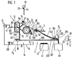
- An open-end spinning device 1 is usually part of an open-end spinning machine 16, which has a plurality of similar open-end spinning devices 1 arranged next to one another on one or both longitudinal sides of the machine.
- Each open-end spinning device 1 has a spinning element which, in the embodiment shown, is designed, for example, as a spinning rotor 10.
- the spinning rotor 10 is mounted in a known manner by means of a shaft 100 and is driven in the exemplary embodiment shown by means of a tangential belt 101.
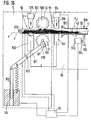
- the spinning rotor 10 is arranged in a rotor housing 102, the interior 103 of which is connected via a suction pipe connection 104 to a vacuum source, not shown.
- a brake 11 can be delivered to the shaft 100 of the spinning rotor, which brake is connected to an actuating lever 13 via a linkage 12 which is only indicated schematically. If the free arm of the actuating lever 13 is acted upon in the direction of the arrow P4, the brake 11 comes to rest against the shaft 100 of the spinning rotor 10, so that the latter is braked.
- the mechanism, which consists of the brake 11, linkage 12 and actuating lever 13, is suitably acted upon by an elastic element against the direction of the arrow P4, that is to say in the direction of the arrow P5, so that when an application is ended in the direction the arrow P4 the brake 11 returns to its release position.
- Figure 1 is the elastic element, which acts on the mechanism consisting of brake 11, linkage 12 and actuating lever 13, designed as a compression spring 130, which is supported on the actuating lever 13 on the arm facing the linkage 12 and on a machine part, not shown.
- a feed device 2 which, in the exemplary embodiment shown, consists of a delivery roller 20 and a feed trough 21 which is pivotably mounted and is elastically pressed against the delivery roller 20 by a compression spring 22.
- Downstream of the delivery roller 20 is a dissolving roller 24 arranged in a housing 23, which during normal production combs fibers (not shown) from a sliver 4 fed to it with the aid of the feed device 2 from a can 41, which fibers pass through a housing 23 in the fiber feed channel 25 extending the spinning rotor 10 are fed to the spinning rotor 10.
- the fibers are deposited in the usual way on a fiber collection point in the spinning rotor 10, from where they are taken up by the end of a thread 44 and continuously bound into the end thereof.
- the thread 44 is drawn off through a thread draw-off tube 26 with the aid of a pair of draw-off rollers 27 and wound onto a bobbin 28 which is driven in a known manner by a bobbin roller 29.
- a thread monitor 14 which monitors the spun thread 44.
- the open-end spinning device 1 is covered by a cover 105, which has a feed hopper 106, and is supported by a machine frame 107.
- a signal device 15 is attached to the cover 105, e.g. in the form of a signal lamp which is connected in terms of control to the thread monitor 14 (usually with the interposition of a control device, not shown).
- a belt feeder 3 is fastened to the machine frame 107 below the rotor housing 102. In the embodiment shown, this is done with the aid of a guide 30, in which the belt feeder 3 is slidably mounted transversely to the machine longitudinal direction.
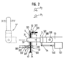
- the belt feeder 3 has a rail or guide rod 300 which extends through the guide 30 and carries a stop 301 at its machine-side end. At its end facing away from the stop 301, the guide rod 300 carries a band holder 31 which, according to FIG. 2, has two band holders 32 and 33 arranged at a distance from one another.
- the tape holder 32 is designed as a helical tape guide and has a slot 322 between its coils 320 and 321, which extends radially outwards from the guide area for the fiber tape 4 enclosed by the coils 320 and 321.
- the last-mentioned band holder 33 is located at a lateral distance a, which has a size which allows the sliver 4 delivered in a can 40 to be received between the band holders 32 and 33.
- this is a clamp formed and consists of a clamping element 330 firmly connected to the guide rod 300 and a second clamping element 331 which is movably arranged for this purpose.
- the clamping element 331 is acted upon by a compression spring 332, which in turn is supported on a spring receptacle 333 which is carried by the guide rod 300.
- the clamping element 331 is thus held elastically in contact with the clamping element 330.
- the free ends 334 and 335 of the clamping elements 330 and 331 are designed such that they move further and further apart from one another towards their free end. These two ends 334 and 335 thus form an insertion guide, which tapers in the transverse direction of the band course between the two band holders 32 and 33 and thus enables the automatic threading of the fiber band 4 in the direction of arrow P3 (see FIG. 1).
- the belt feeder 3 is - as FIG. 1 clearly shows - so high above the can 41 that the sliver 4 extending from the receiving position, which is below the feed device 2, but above the can 40, to the open-end spinning device 1, via others Cans 41 is guided away and can not come into contact with the sliver 42 which is located in the can 41 placed between the feeding device 2 and the can 4 and which usually extends to above the upper edge of the can 41.
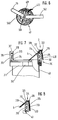
- a tape feeder 5 is provided to accommodate the sliver 3 extending between the two sliver holders 32 and 33.
- this consists of a controllable clamp in the form of a pair of overhung rollers 50, 51, of which the roller 50 can be driven by a motor 500 with the interposition of a clutch 501 the roller 51 is designed as a loose roller, which is driven by the driven roller 50, in operation via the sliver 4 inserted into the pair of rollers.
- This roller 51 which is designed as a loose roller, can be removed from the roller 50 by pivoting, so that a wedge-shaped gap 52 is formed between the two rollers 50 and 51.
- the pivot mechanism for the roller 51 has not been shown in FIGS. 1 and 2.
- the belt feeder 5 is also pivotally mounted as a whole on a rod 53 (see pivot point 530 in FIG. 2).
- An arm 54 extends laterally from the belt feeder 5 and is connected in an articulated manner to the armature 540 of an electromagnet 541.
- a new can 40 While the spinning station is still operating normally, a new can 40 must already be provided and the sliver 4 must be inserted into the sliver feeder 3 so that when the old sliver runs out, a new sliver is already ready to be taken up by the sliver feeder 5 and to be presented and handed over to the open end.
- Spinning device 1 is provided.
- the new sliver 4 is removed from the can 40, which is essentially placed under the sliver 3, and inserted with its beginning (beginning of the sliver 43 - FIG. 2) into the sliver holder 33 above the can, which is done automatically or by hand - Can be done by a simple movement in the direction of arrow P3 (Fig. 1).
- Ends 334 and 335 of the two clamping elements 330 and 331 form a conical insertion slot (or an insertion guide), and moreover in that, contrary to the action of the compression spring 332, the elastically mounted clamping element 331 moves so far from the other clamping element 330 that the beginning of the tape 43 of the sliver 4 is held securely near its free end between the two clamping elements 330 and 331.
- the sliver 4 By moving the sliver 4 in the direction of arrow P 1 (see Figure 2), the sliver 4 is inserted into the sliver holder 32, in which the sliver 4 is axially movable.
- the thread monitor 14 If the old sliver 4 now runs out, the thread monitor 14 is actuated since the thread 44 breaks in the absence of the sliver 4. The thread monitor 14 sends a signal to the signal device 15 of the open-end spinning device 1 in the usual way.
- the tape feeder 5, which is initially in a rest position 5 ', is caused by this signal to move from the rest position 5' (see FIG. 1) transversely to the sliver 4 in the take-up position into the tape take-up position (FIG. 2) .
- the roller 51 is moved against the roller 50, so that the sliver 4 is clamped between the two rollers 50 and 51.
- the sliver 4 can remain in the sliver holder 32 for any length of time, namely until it is unthreaded - automatically or by hand - at any time, for example when a new sliver is to be inserted into the sliver feeder 3, since its axial mobility results from the tape holder 32 is not affected.
- the feed device 2 is driven in coordination with the displacement movement of the belt feeder 5 or in coordination with the drive of the roller 50 of the belt feeder 5.
- the motor 500, the clutch 501 and the electromagnet 541 are in one common control device 93 is connected (FIG. 14), with which the drive of the feed device 2 is connected, possibly with the interposition of a machine-side control device 18 (see FIG. 18).
- a single drive 200 is provided for the delivery roller 20, which is controlled by the control device 93 and / or 18 (FIG. 18).
- the synchronization of the tape application and the switching on of the feed device 2 can take place in various ways.
- the control device 93 which controls this movement, generate a control pulse for switching on the individual drive 200 of the delivery roller 20.
- the delivery roller 20 is thus driven, which consequently grasp the fiber sliver 4 fed to it by the belt feeder 5 and can feed the opening roller 24 to dissolve it into individual fibers.
- the feed device 2 is only switched on in order to be able to take up the sliver 4 that has been put on. It is also important that there is no excess tape between the rollers 50, 51 of the belt feeder 5 and the feed device 2.
- the tape feed speed is therefore matched to the tape feed speed via the control devices 18 and 93.
- the swiveling speed with which the belt feeder 5 approaches the feeding device 2 is adapted to the peripheral speed of the delivery roller 20 and thus to the feeding speed of the feeding device 2.
- a switching flag 202 is arranged on the delivery roller axis 201 of the delivery roller 20, which is driven by a single drive 200, and is scanned by a light barrier 203 (see light source 204 and photo cell 205).
- Corresponding commands are then delivered to the control device 93 via a line.
- the control device 93 controls the speed at which the belt feeder 5 approaches the feed device 2 and feeds the sliver 4 into the feed device 2 in accordance with this pulse sequence predetermined by the delivery device 2.
- This speed of the belt feeder 5 is either the same as or even slightly less than the peripheral speed of the delivery roller 20, so that a loop formation in the supplied sliver 4 is avoided with certainty.
- the belt feeder 5 is brought up to the feed device 2 at any speed.
- the belt feeder 5 is then stopped and the motor 500 of the roller 50 is switched on.
- This motor 500 is now matched to the speed of the feed device in such a way that the roller 50 either has the same peripheral speed as the delivery roller 20, or else the roller 50 is driven at a somewhat lower peripheral speed, so that the sliver 4 between the rollers 50, 51 and the feeder 2 is slightly warped.
- the belt feeder 5 After the sliver 4 has been introduced into the feed device 2 - which, depending on the training, can normally be assumed after a certain time or what at the end the pivoting movement of the belt feeder 5 should be the case - the belt feeder 5 is controlled so that it releases the sliver 4 and can return to its basic position. The pair of rollers consisting of rollers 50, 51 is stopped. This completes the tape application process.
- a thread break was produced by the sliver 4 previously fed to the feed device 2.
- This re-spinning is carried out in the usual way by cleaning the spinning element, returning a thread end suitable for spinning up to the fiber collecting surface of the spinning rotor 10 or other spinning element, fibers being supplied to the fiber collecting surface by switching on the feed device 2 by appropriate time control Tie the end of the thread, which is then drawn off again by the spool 28 and later by the pair of draw rollers 27 from the spinning rotor 10 or other spinning elements (eg friction spinning elements).
- piecing methods that can be used in connection with the method and the device according to the invention, for which reason a detailed description of piecing is not given.
- the spinning rotor 10 is braked during the initial feeding of the sliver 4 to the opening roller 24 by acting on the actuating lever 13 in the direction of arrow P4 for the reasons described. Due to the negative pressure acting in the rotor housing 102 through the intake manifold connection 104, the fibers fed through the fiber feed channel 25 into the spinning rotor 10 are thus removed again from the rotor housing 102, so that the fibers in the spinning rotor 10 cannot form a fiber ring.
- the piecing is prepared, which - as mentioned - is carried out in the usual way.
- the feed device 2 is shut down for a predetermined time and only then put into operation again, so that a fiber ring is formed in the spinning rotor 10.
- a start of the thread 44 which has been retrieved from the spool 28 and prepared for spinning, is placed on this fiber ring and connected to the fiber ring, whereupon the withdrawal of the thread 44 starts again in a known manner.
- the fibers not only get the opportunity to get into the spinning rotor 10, but are already sucked off at the circumference of the opening roller 24 until the beginning of the thread 44 has been returned to the spinning rotor 10 on its fiber collecting surface. The removal of the fibers is then stopped and the fiber stream is fed back into the spinning rotor 10 so that it can connect to the thread 44 already located there, which is then drawn off in the usual way.
- a prerequisite for a piecing process to be able to be carried out in the case of an open-end spinning device 1 is that the tape application process has been carried out successfully.
- a tape monitoring device 520 is provided according to FIG. 14.
- this is essentially formed from the roller 50 and a sensor 503 and is thus arranged on the belt feeder 5.
- the roller 50 has markings 502, which are scanned by the sensor 503 of a scanning device.
- the markings 502 on the roller 50 are arranged very closely next to one another in the exemplary embodiment shown, in that the markings 502 have a maximum angular distance of 90 °, but if possible - depending on the roller diameter - considerably less.
- the sensor 503 is connected to the belt feeder 5 or its control device 93, to which the motor 500 of the roller 50 and the electromagnet 541 for the roller 51 are also connected.
- a signal lamp 94 is also connected to the control device 93.
- the roller 50 is not driven, in contrast to the state described above, since the sliver 4 is not transported, so that the sensor 503 cannot deliver any pulses to the control device 93.
- the control device 93 now causes the signal lamp 94 to light up, so that the operator can initiate the tape application process again.
- the tape application process can, of course, also be initiated automatically, the signal lamp 94 only lighting up if the tape application has not been successfully completed even after several attempts.
- failed attempts count program step N
- FIG. 20 shows a part of a perspective view modified design of a belt feeder 5 with the roller 50 driven by a motor (not shown in FIG. 20) and the roller 51, which is designed as a loose roller.
- the aforementioned wedge-shaped gap 52 is formed between the overhung rollers 50 and 51.
- the two rollers 50 and 51 are mounted in a housing 504, the side 505 of which faces the rollers 50 and 51 serves as a belt support and thus prevents that the sliver 4, especially when it is fed to the feeding device 2, can slip out of the pair of rollers 50, 51.
- the two rollers 50, 51 are provided with a thread-like corrugation or profiling 506 and 511, which is helical.
- the profiles are inclined to the surface lines of the rollers 50, 51 that they approach each other when the rollers 50, 51 rotate in the feed direction, ie in the direction of the beginning of the strip 43.
- the corrugation or profiling 506 and 511 can also take over the task of the markings 502 shown in FIG.
- the roller 51 When driving the roller 50 in the direction of arrow P19, the roller 51 is driven via the sliver 4 in the direction of the arrow P20, with a force being exerted on the sliver 4 in the direction of the arrow P21, through which the sliver 4 in the direction of the Gap 52 delimiting side 505 of the housing 504 forming a band support is moved.
- the band support can also be designed in another suitable manner.
- the receiving position for the fiber sliver 4 is determined by the sliver holders 32 and 33 in the working position.
- the two strap holders 32 and 33 are essentially on the same horizontal Level arranged.
- the two tape holders 32 and 33 can also be arranged one above the other, whereby in principle nothing essential changes for the tape take-up by the tape feeder 5.
- the belt feeder 5, which can possibly also be formed by the pair of rollers 50, 51 shown, then only has to be rotated by 90 ° in comparison to the embodiment shown in FIG. 1 for the reception of the fiber sliver 4.
- the sliver holder 33 is designed as a clamp in the previously described embodiment. However, this is not absolutely a requirement. So the tape retention can also by other means such. B. suction air or a Velcro can be achieved. Both strap holders 32 and 33 can also be designed as restraining means. A solution in which both strap holders 32 and 33 are designed both as a guide that allows axial movement and as a clamp that prevents them from slipping out of the strap holder 32 and 33 is also possible.
- the sliver 3 is slidably attached to the open-end spinning machine 16. If the belt feeders 3 protruding laterally from the open-end spinning machine do not interfere, they can also be rigidly attached to the machine frame 107.
- the belt feeder 3 is a separate device, but it is also possible to provide the receiving position in or on the can 40, etc., ie to provide the can 40 as a belt feeder 3 and / or train and that Submit sliver 4 through the can 40 of the open-end spinning device 1 or other textile machine for reception by the sliver feeder 5.
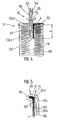
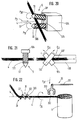
- FIG. 4 A first embodiment of this type is explained with the aid of FIG. 4. As this figure shows, is in the middle of the can 400, i. in the center of the sliver 4 deposited in the can 40, a space into which the beginning of the sliver 43 protrudes.
- a length b of at least 100 mm and a maximum of 200 mm has been found for this turned out to be particularly advantageous. If the strap end is shorter than 100 mm, there is a risk that the strap end will be pulled out of the can center 400.
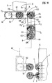
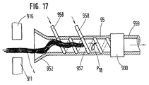
- a belt feeder 55 is also provided, which, in contrast to the belt feeder 5 shown in FIGS. 1 and 2, is of pneumatic design.
- This belt feeder 55 consists essentially of a base body in the form of a tube 550, which is closed by a wall 551 at its front end which can be brought into the center of the can 400.
- the tube wall is designed as a sieve 552 on a surface that extends along a producer line over part of the circumference of the tube 550.
- the tube 550 is connected at its end, not shown, to a vacuum source, so that in Area of the sieve 552, a suction air flow flowing into the tube 550 can be generated. If the band feeder 55 is now inserted into the can center 400 and rotated about its longitudinal axis (see arrow P Pfeil), the sieve 552 arrives in the region of the band end forming the later band start 43 and holds it there.
- the belt feeder 55 can now be moved vertically upwards out of the can center 400. He takes the end of the tape with him.
- the belt feeder 55 is now brought in front of the feed hopper 106 of the open-end spinning device 1 (FIG. 1), and the end of the belt which now forms the beginning of the belt 43 is moved by a suitable movement of the belt feeder 55 into this feed hopper 106 into the clamping area between the delivery roller 20 and the feed trough 21 introduced so that the feed device 2 can take up the sliver 4 and transport it further.
- the band feeder 55 is not moved to the extreme end of the sliver 4 during the insertion movement into the can 400, so that after the sliver 4 has been taken up by the Ribbon feeder 55 extends a predetermined ribbon length beyond the end of ribbon feeder 55. This free end of the sliver 4 can then be inserted into the feed device 2 by a movement through 180 °.
- the screen 552 is divided into two sub-screens 552a and 552b by an intermediate wall which merges into a longitudinal wall 553 of the essentially tubular belt feeder 55.
- two chambers 554 and 555 are formed in the belt feeder 55, each of which is optionally connected to a not shown by switching valves (not shown) Vacuum or can be connected to an overpressure source.
- both the chamber 554 and the chamber 555 are subjected to negative pressure.
- the belt feeder 55 is then brought into the correct position for the transfer of the sliver 4 to the feed device 2, which can be done both by rotating in the direction of the arrow P6 about its longitudinal axis and by pivoting through 180 °. If the belt feeder 55 is then in front of the feed hopper 106 (see FIG. 5), the chamber 554 is first subjected to excess pressure, so that the beginning of the belt 43 is blown into the feed hopper 106.
- the belt feeder 55 is then raised in the direction of the arrow P7 until the partial screen 552b also reaches the area in front of the feed hopper 106.
- the second chamber 555 is now also subjected to excess pressure, so that the fiber sliver 4 can further enter the feed hopper 106 and the feed device 2. Since the switching of the air conditions in the chambers 554 and 555 has to take place as a function of the position of the belt feeder 55 relative to the feed device 2, it is advantageous if this changeover takes place as a function of the movement or position of the belt feeder 55, but one is Time control for this purpose is also conceivable.
- the screen 552 can also have more than only two sub-screens 552a and 552b and correspondingly more than only two chambers 554 and 555, which are then also individually controlled, as explained below using the example of a tape dispenser with the aid of FIG. 9 becomes.
- FIG. 6 shows an alternative solution, in which the band end 430 extends outward beyond the can rim 401 and hangs outside the can 40, and here, as in the exemplary embodiment described above, the downwardly projecting band end should have a length that is between 100 mm and Is 200 mm.
- a belt feeder 56 which is designed essentially in the same way as the belt feeder 55 shown in FIG. 4, can be used.
- the belt feeder 56 is attached to the free end of a swivel arm 560, which can be rotated about a swivel axis 561.
- the pivot axis 561 is located at the end of a support arm 562, which can be placed with its pivot axis 561 in the center of the can 40 for receiving the band end 430.
- the belt feeder 56 is connected via lines (not shown) to corresponding sources of negative pressure or positive pressure, so that corresponding suction or compressed air flows can be generated in the belt feeder 56.
- the support arm 562 is mounted in a suitable manner on the open-end spinning machine 16, expediently with the aid of a device which can be moved along the machine and is thus enabled to operate more than just one open-end spinning device 1.
- the swivel arm 560 with the band feeder 56 is brought into the position shown in FIG. 6, in which the swivel axis 561 is located essentially centrally over the can 40. Now the swivel arm 560 is pivoted by at least 360 ° along the can rim 401, so that the belt feeder 56 surely passes the belt end 430 and takes it up in a defined manner due to the suction air draft prevailing in it.
- this belt feeder 56 works in the same way Way like that belt feeder 55, which is described with the aid of FIGS. 4 and 5.
- a different arm instead of a swivel arm 560 if the can 40 is given a rotary movement instead of the arm. All that is essential is the relative movement between the sliver 4 and the sliver feeder 56, so that the sliver 4 reaches the area of the sliver feeder 56 and can be picked up by the latter.
- the mechanical and pneumatic design, as described above, are merely exemplary embodiments. Other designs for taking up the sliver by adhesion due to icing or by electrostatic charging are also possible.
- FIG. 7 shows such an exemplary embodiment in which the belt feeder 3 has a belt holder 310 which is detachably fastened to the can 40.
- the band holder 310 in this case has a ring 311 which is fastened to the outer circumference of the can 40 with the aid of a snap closure 312. At several, at least two points on the circumference, the ring 311 has upwardly projecting bearings 313 which carry a resilient clamping element 314.
- the bearings 313 have an arm 316 with respect to the pivot axis 315 for the clamping element 314 on their side facing away from the ring 311, on which arm a compression spring 317 is supported.
- the Compression spring 317 is still supported on an arm 318 of the clamping element 314.
- the arm 316 of one of the bearings 313 ends in a band holder 323 designed as a band guide, which in the embodiment shown is open in the form of a "U" on the side facing away from the bearing 313 and forms a band feeder 3.
- the sliver 4 is inserted into this sliver holder 323.
- the band holder 324 has been modified somewhat compared to the band holder 323 of FIG. 7 in the receiving position on the relevant feed device 2.
- a further lever 325 is arranged on the pivot axis 315, on which the compression spring 317 is supported instead of the arm 316 of the bearing 313. In this way, the lever 325 forms an elastic clamp together with the arm 316.
- the strap end 430 hangs down from the strap holder 323 or 324 and can be picked up by a strap feeder in the manner shown in FIGS Transfer of the sliver 4 to the feed device 2.
- the device according to FIGS. 7 and 8 is particularly suitable for the manual insertion of the fiber sliver 4 into the sliver holder 323 or 324, since the ring 311 can generally only be placed on the can 40 after this can 40 has covered the distance 7 ( see Fig. 11) at which it was filled.
- the end of the band 430 which forms the beginning of the band in further operations, can be brought into its ready position or into its receiving position by inserting it into the band holder 323 or 324.
- the sliver 4 then remains inserted in this band holder 323 or 324 for the transport and possibly for further steps such as preparing the band application or the band application itself.
- the tape feeder 3 fastened to the machine frame 107 according to FIG. 1 can be constructed in a similar manner to the tape feeder 3 shown in FIGS. 7 and 8 and likewise have only a single tape holder 323 and 324 instead of two tape holders 32 and 33.
- the sliver 3 is arranged at a vertical distance above the upper can edge 401, so that the sliver 4 is sufficiently high above other cans 41 (see FIG. 1) to the feeding device 2 can be brought.
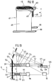
- FIGS. 23 to 25 show a further modification of a device in which the band end 430 is introduced into a holder when it is brought into the receiving position, in which the fiber band 4 remains inserted during further steps of the band application.
- Figure 23 shows a flat jug 411 in side view. Such a pitcher design will be discussed in more detail in connection with FIG. 12.
- the can 411 is shown to better show the arrangement to the right of its operating position below a delivery device 2 of the spinning machine.
- This delivery device 2 comprises a conventional delivery roller 20 and has a recess 206 for receiving a novel trough lever 210, which is now attached to the can 411 by a rod 319.
- the trough lever 210 engages in the recess 206, so that a belt end 430 held by the trough lever 210 is brought into interaction with the delivery roller 20.
- the sliver 4 is pulled out of the can 411 and introduced into the spinning station.
- FIG. 25 shows three such open-end spinning devices 1, each with a delivery device 2 and a can 411 associated with this spinning device 1, together with its rod 319.
- the cans 411 are in their operating position by guides 164 and 165 in the vicinity of the upper and / or lower end of the Can 411 led.
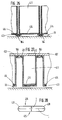
- FIGS. 26 and 27 each show a variant for the formation of guides for a can 40, 41 or 411.
- the can stands on rails 164 which are fastened to the bottom 19 below the open-end spinning devices 1.
- Additional guides 165 can be provided for the side walls of the can, as has already been shown in FIGS. 23 and 25.
- the can 411 is above the bottom 19 of rail-like guides 166 in the machine frame 107 worn.
- each can 411 is provided on the upper edge with a ledge 412 protruding outwards, which slides on the guides 166.
- the can walls have inwardly projecting edges 413 at the lower edge, which carry a loose can bottom 414 in each can 411.
- the can bottom 414 can be moved relative to the can walls by means provided on the machine, not shown. H. by external action - the jug 411 itself is not provided with any means to cause the jug bottom 414 to move relative to the side walls.
- This arrangement is useful because the introduction of the sliver 4 into the open-end spinning devices 1 does not cause the sliver 4 to warp.
- the sliver 4 can therefore extend from the delivery device 2 to the can bottom 414, the sliver 4 being drawn into the open-end spinning device 1 by the delivery device 2, without causing any distortions (yarn number fluctuations).
- the loose can bottom 414 also enables the can 411 to be filled with ribbon loops according to a predetermined pattern.
- FIG. 9 shows an automatically operating device which enables the sliver 4 to be placed in a position required for later picking up.
- a tape feeder 61 which in principle is like the tape feeder 55 or 56 is formed and, like this one, has a divided screen 552 and several chambers 554, 555 and 556 which can be optionally and individually connected to a vacuum or an overpressure source, is now moved in the direction of arrow P8 under the turntable 6 and up to the outlet opening 60 brought into a position 61 ', whereby the sliver 61 detects the deflected sliver 4. This sliver 4 is then cut in the usual and therefore not shown manner between sliver 61 and turntable 6.
- the can 40 is now transferred with the end of the tape deposited in this way to the open-end spinning device 1 (FIG. 1) in the receiving position, where a new sliver 4 is to be made available and where the sliver 4 is previously made with the aid of FIGS. 4, 6, 7 or 8 is recorded for the transfer to the relevant feed device 2.
- both the ready position and the receiving position can be provided on the can 40, from which the sliver 4 to be fed to the feed device 2 is to be removed.
- this ready position or the receiving position can either be in the center of the can 40 or in its peripheral region be provided.
- the sliver 4 can be taken up by a (not shown) sliver receiver - which can in principle be designed like the described sliver 61 or sliver feeder 55 or 56 - and inserted into a sliver 3 located there (see FIG. 1) so that it is there can be picked up by a belt feeder 5, 55 or 56 and transferred to the feed device 2.
- the sliver can also take the sliver 4 directly, i.e. without the interposition of a separate tape feeder 3, to the tape feeder 5, 55 or 56, so that the tape pickup also takes over the function of a tape feeder in this case.
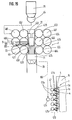
- FIG. 10 shows another device in which the movable separating web 620 of a belt separating device 62 is arranged in the rotating plate plate 600 receiving the rotating plate 6.
- a clamping fork 621 works together with the underside of the turntable plate 600 and with the separating web 620.
- the separating fork 621 is moved from the bottom upwards against the underside of the turntable plate 600, so that this separating fork 621 presses the sliver 4 against the underside of the turntable plate 600.
- the separating web 620 is now moved down between the two prongs 622 of the separating fork 621 and in doing so exerts an ever increasing pressure on the sliver 4 until it finally breaks.
- a switching flag 601 is provided at a suitable point on the turntable 6 and is scanned by a sensor 602, which is connected via lines 603 in a suitable manner to a control device (not shown).
- This control device acts on the drive of the turntable 6 and stops it when the turntable 6 is in the desired position for severing the sliver 4.
- the can 40 has been moved for the separation of the sliver 4 by a predetermined distance in such a way that the distance between the can edge 401 and the separating web 620 corresponds exactly to the length b by which the band end 430 is later to hang down on the can 40.
- the can 40 can be equipped with two lugs 402 (see also FIG. 12) which receive this band end 430 between them.
- a new can 410 has been pushed under the turntable 6 at the same time that the can 40 has been pushed out of the path 7.
- the defined positioning of the band end 430 on the can edge 401 can also be carried out in another suitable manner.
- the can 40 is moved out of the filling station after it has been filled at the filling station - which in the case of the section 7 described is formed by its delivery head 70 and the space below it - without the sliver 4 being fed in beforehand by the delivery head 70 is ended.
- the subsequent sliver 4 arrives on the trailing side of the can 40 and thus in a largely defined position.
- the sliver feed is stopped in such a way that the end 430 of the band protruding beyond the edge 401 of the can reaches the desired end Length b does not exceed.
- the sliver 4 is cut through in a suitable manner, for example as previously described in connection with FIG. 10, the sliver end 430 hanging outside the can 40 from the can edge 401 also has a length b within the desired tolerances.
- a device can be provided on the delivery head 70 or on the underside of the turntable plate 600, by means of which the sliver 4 is placed centrally with respect to the direction of extension of the can 40 and which, for example, in the form of two transverse to the can extension direction (see arrow P12 in Figure 11) movable band centering 74, 740 (see arrows P9 and P10) is formed.
- the band centerings 74, 740 are located on the delivery head 70 at a point between the outlet opening 60 of the turntable 6 and the can rim 401 of the can 40 after it has left the filling station.
- the two band centers 74 and 740 are at the same level as the sliver 4 on both sides of the sliver 4 extending from the delivery head 70 to the can 40 Ejection movement ended or at least almost ended, the band centerings 74, 740 are brought closer to one another, grasp the fiber band 4 and bring it to the center line of the can web between the filling station and the subsequent rest position of the can 40.
- the band end 430 comes to the center Extending direction (arrow P12) to lie on the trailing can side on the can rim 401.
- the can 40 has guides which hold this can 40 in the desired position relative to the path 7, ie to the turntable 6. This is explained below with reference to FIG. 11, which shows a line 7 with its delivery head 70, a vehicle (transport carriage 8) for transporting the can 40 from the line 7 to the open-end spinning device 1 and the open-end spinning machine 16 with a large number of open-end Spinning devices 1 shows.
- the can 40 does not lose its orientation from the delivery head 70 of the line 7 until the take-up position is reached by the start of the belt 43 in the vicinity of the open-end spinning device 1, the can 40 has a guide which is guided by guides on the line 7 and on the open-end Spinning machine 16 works together.
- the can 40 has a rectangular profile, the sides 403, 404, 405 and 406 of which serve as guides.
- the guides formed by the sides 403 and 405 work together with guides 700 and 701, between which the cans 40 are conveyed under the delivery head 70 and later out of their position under the delivery head 70. Pages 404 and 406 also serve as guides for cans 40 and cooperate with guides 702 and 703.
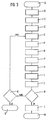
- the can 40 is presented to route 7 in the usual and therefore not shown manner. It is then filled in its position under the delivery head 70 (program step A, FIG. 3). After filling the can 40, it is ejected in the direction of the arrow P 12 from the path 7 and the band end 430 is brought into the desired position, ie into its ready position, from which it can later be resumed for the further operations (program step B). The tape end 430 is secured in this position, which by the two lugs 402 can happen (program step C). The can 40 is then pushed along the arrow P13 and possibly P14 on the trolley 8.
- the transport carriage 8 also has guides 81, 810, 811 and 812. The can 40 is thus secured against rotation during the entire transport duration and can therefore neither change its relative rotational position with respect to the route 7 nor with respect to the transport carriage 8 during its entire transport.
- the provision of the sliver 4 takes place in the manner described above, namely according to the exemplary embodiment shown in FIG. 10 between the lugs 402.
- the transport carriage 8 with the can 40 deposited thereon and possibly one or more further cans is now along the line 80 moved to the open-end spinning machine 16 in front of an open-end spinning device 1, where a new can 40 is required.
- Guides 160 and 161 are also provided there per open-end spinning device 1, so that the can 40 cooperating with these guides can be brought into its receiving position below the open-end spinning device 1 without changing its rotational position relative to the open-end spinning device 1 (program step D).
- the sliver is picked up and transferred to the open-end spinning device 1 in the manner described above (program steps E, H and I).
- the lugs 102 or the free end of the belt is not on the side of the can 40 facing away from the open-end spinning device 1, but rather on the side facing the open-end spinning device 1.
- This can be done by unloading the trolley 8 - in contrast to the embodiment according to FIG. 11 - not to the right but to the left and the cans 40 of open-end spinning devices located there 1 can be fed.
- a turntable (not shown) on the trolley 8 per can 40 so that the cans 40 can be brought into the desired rotational position by rotating these turntables, in which the sliver 4 can then be moved with the aid of a simple, not on a swivel arm 560 (see FIG. 6) arranged belt feeder 5 (FIG. 2) or 55 (FIG. 4) can be received.
- corresponding ejection brackets can be provided on the trolley 8, which can be controlled from the open-end spinning device 1.
- the transport carriage 8 is connected in a manner not shown to the open-end spinning device 1 or to the central control device (FIG. 18) of the open-end spinning machine 16.
- the guides for maintaining a defined position the cans 40 can be designed differently, as the exemplary embodiments described above show.
- the guides connected to the can 40 can be releasably attached to this can 40 or to the tape feeder 3 carried by the can 40 and, if desired, by correspondingly flat outer surfaces of the can 40 (see pages 403, 404, 405 and 406 of the figure) 18 can 40 shown) or the ring 311 (see Figure 7) are formed.
- the jug 411 does not have a round profile, but is elongated. Its two long sides can thus serve as a guide, with the help of which the can 411 is guided from the route 7 to the open-end spinning device 1 between two guides 700, 701 or 81, 810 or 160, 161 (see FIG. 11).
- lugs 402 can be provided on the can 411, between which the band end 430 is held, which - as described - projects with a length b over the edge of the can 411 and hangs down there.
- FIG. 29 shows a series of twenty-three spinning positions of an open-end spinning machine and a transport carriage 8 for transporting flat cans (cans 411) and for exchanging such cans 411 at the spinning positions.
- the trolley 8 comprises a can-receiving part 82 and two end parts 83, 84.
- the can-receiving part 82 is divided into compartments by partitions 820, each compartment being suitable for receiving a flat can (can 411) by moving the flat can in its longitudinal direction.
- Each end portion 83, 84 carries a post 830, and the posts in turn carry a bar 831, which serves as a guide rail for a can manipulator 85.
- the can manipulator 85 can be moved in the longitudinal direction of the bar 831 and can thereby be delivered to the individual compartments of the can-receiving part 82.
- the can manipulator 85 comprises its own rail 850, which is perpendicular to the beam 831 and serves as a guide rail for a can slide 851.
- the can slide 851 comprises a gripper (not shown) which, by moving in the direction of the central plane of the open-end spinning machine, pushes the can 411 taken from the transport carriage 8 into the operating position in the machine or by moving it away from the central plane of the machine 411 pulls from their operating position onto the transport carriage 8.
- a gripper not shown
- Each end part 83, 84 of the transport carriage 8 also has wheels 86 which enable the movement of the vehicle in directions perpendicular to the long side of the cans which have been received.
- the transport carriage 8 comprises a drive (not shown) and possibly a controller which controls a steering system (not shown) for the wheels 86.
- the trolley 8 is guided by a system control to a selected spinning station at which the can 411 is to be replaced.
- a suitable positioning system (not shown here)
- the transport carriage 8 is initially positioned such that the empty compartment is aligned with the spinning station (open-end spinning device 1), where the can 411 is to be exchanged.
- the can manipulator 85 is assigned to the empty compartment and the can pusher 851 is moved inwards relative to the machine so that its gripper (not shown) can be exchanged can 411.
- the can 411 to be replaced is pulled into the previously empty compartment of the transport carriage 8.
- the transport carriage 8 is then moved to align a compartment filled with a full can 411 with the relevant spinning station.
- the can manipulator 85 is moved along the bar 831 in order to deliver the can manipulator 85 to the newly introduced can 411. By moving the can manipulator 85 inwards (opposite the machine), this full can 411 is then moved into the operating position.
- the transport carriage 8 can now be delivered to another selected spinning station, where the procedure is repeated, the empty compartment on the transport carriage 8 now not being in the original position, but instead in the place of the full can 411 last delivered to the machine.
- the empty compartment is gradually moved until all full cans 411 have been inserted into the open spinning machine and replaced with empty (or at least to be replaced) cans 411.
- the trolley 8 is then moved back to route 7.
- the can-receiving part 82 of the transport carriage 8 need not be rigidly connected to the end parts 83, 84 of the transport carriage 8. As indicated in FIG. 29 by double arrows 821, the part 82 can also be height-adjustable relative to the end parts 83, 84 in order to bring the cans 411 at the same height from the part 82 into their loading or unloading position on the line 7 or the open-end spinning machine or another Textile machine or device - and of course also in the opposite direction - to be able to move. Similarly, too other elements such as B. the tape feeder 5, tape start preparation device 9 (which will be described below) height-adjustable on the trolley 8 stored.
- the flat can 411 shown in FIGS. 12 and 28 has two parallel side walls 415, 416 which define the can width i.
- the can 411 also has two end pieces 417, 418 which connect the side walls and define the can length j.
- rounded end pieces 417, 418 are shown, but these are instead perpendicular to the side walls 415, 416 or can be designed as polygons.
- the jug length j is significantly larger (e.g. three to four times larger) than the jug width i, which is essentially the width of a spinning station, i. H. corresponds to an open-end spinning device 1. In this way it is achieved that the capacity of the flat jug 411 corresponds to the capacity of a conventional round jug.
- the capacity of a flat jug 411 should correspond to the capacity of a round jug with a diameter of 450 to 500 mm. If it is assumed as an example that the diameter of a conventional round can is approximately 457 mm, then a flat can (can 411) according to FIG. 28 with a width of 230 mm and a length of 780 mm has a somewhat larger capacity than the round can. In other words, the length of the flat can does not have to be twice the round can diameter in order to give the same capacity.
- the height of the can is given by the construction of the spinning machine frame, since the cans 40, 41 or 411 have to be placed under the spinning station.
- the beginning of the band 43 (through the Band end 430 is formed) is not fed unchanged to the open-end spinning device 1, but is still especially prepared for transfer to the feed device 2. Due to external influences during the time from the insertion of the sliver 4 into the sliver holder 31 (FIG. 2) or 323 (FIG. 7) or 324 (FIG. 8) or also inside the can 40 (FIG. 4) or on the can rim 401 (FIG 6) namely the sliver 4 can be moved or pulled out of the can 40, 41 or 411, so that the state and / or the length of the sliver 4 changes.
- the beginning of the band 43, with which the sliver 4 is to be fed to the open-end spinning device 1 always has the same quality.
- the tape start 43 to be applied is brought to a defined length.
- a tape start preparation device 9, as shown in FIG. 13, is particularly useful for this.
- a controllable clamp 91 is assigned to the band holder 31 in the embodiment as shown in FIG. 2, or in the embodiment as shown in FIG. 13, or in another embodiment, which can in principle be designed differently.
- this clamp 91 is arranged stationary and has a carrier 910, at one end of which a stop 911 is arranged.
- an electromagnet 914 is arranged on the carrier 910 and is connected to a counter-stop 916 via an armature 915.
- This counter stop 916 can be brought into contact with the stop 911 or clamp a sliver 4 between it and the stop 911.
- the armature 915 is guided by a spring support 912, which in turn is supported by the carrier 910 between the counter-stop 916 and the armature 915 is provided.
- a compression spring 913 is supported at one end on the counter stop 916 and at the other end on the spring support 912. If the electromagnet 914 is de-energized, ie in the dropped state, the compression spring 913 acts on the counter stop 916, so that the sliver 4 is clamped between it and the stop 911. If, on the other hand, the electromagnet 914 is excited, the counter-stop 916 is removed from the stop 911 against the action of the compression spring 913, so that the sliver 4 is released.
- the clamp 91 works together with the belt feeder 5.
- a device serves as the belt feeder 5, which is designed essentially in the same way as the clamp 91.
- a clamp 512 is arranged at its free end, which has a stop 571 with which a counter-stop 573 acted upon by a compression spring 572 cooperates.
- the counter stop 573 is connected to the armature 574 of an electromagnet 575.
- the armature 574 is guided by a spring support 576, which also supports the compression spring 572 acting on the counter stop 573.
- a pinion 577 is mounted, with which a rack 578 which can be driven by a drive 579 cooperates and can be moved back and forth in the direction of the double arrow P 1.
- the rack 578 with its drive 579 thus forms a drive for changing the relative distance between the terminal 91 and the terminal 512 of the belt feeder 5.
- the two terminals can be controlled synchronously, at least with regard to the closing, in order to ensure the separation function.
- the sliver 4 is then inserted into the two clamps (which come from stop 571 and counter stop 573 existing terminal 512 and terminal 91) inserted. Then, by moving the rack 578 towards the stop 571, the clamp 512 of the belt feeder is pivoted so that it moves away from the clamp 91. The sliver 4, which is held in the clamps 91 and 512, is thus pulled apart until it breaks.
- a minimum distance c is provided between the shown starting position of the clamp 512 and the clamp 91, which is equal to the staple length (average staple length) of the fibers contained in the fiber band 4, that is to say is predetermined by the stack length of the fibers contained in the fiber band 4.
- a band start 43 is created in this way, which is particularly suitable for insertion into the feed device 2. Since the fiber ends are distributed fairly evenly in the sliver 4, the tearing of the sliver 4 causes thinning and tapering of the beginning 43 of the sliver, which is therefore particularly suitable for insertion into the feed funnel 106 (see FIG. 1).
- the two electromagnets 914 and 575 and the drive 579 of the rack 578 are common Control device 93 connected, which ensures that the movement of the clamps 512 and 91 of the tape start preparation device 9 takes place only after the counter stops 573 and 916 abut against the stops 571 and 911, respectively.
- a cutting device 34 As shown in Figure 2, it is also possible to cut the sliver 4, a cutting device 34, z. B. scissors or the like to be arranged on an arm 302 of the guide rod 300 of the sliver 3.
- This cutting device 34 simultaneously fulfills the task of a tape measuring device and can then be triggered manually or electrically in a manner not shown, if desired. If an electro-mechanical separation of the sliver 4 is not required, it may also be sufficient to provide only the arm 302 with a scale, not shown, for the dimension of the length of the sliver start 43, then shortening the sliver 4 using a simple one , can be done, for example, by hand in the place of the cutting device 34 shown in FIG. 2.
- the cutting device 34 or the scale, not shown, thus forms a tape length measuring device which is attached to the tape feeder 3 and by means of which the length b of the tape start 43 desired for the tape application can be generated or checked. If the can 40 serves as a belt feeder 3, a marking on the circumference of the can may also be sufficient for this.
- the sliver can also be separated in other ways. This makes it possible to use an injector through which a medium is directed onto the fiber sliver 4 (medium pulse). If necessary, thermal burning of the fiber sliver is also possible, particularly in the case of natural fiber material, in which there is a risk the fusion of the fibers is less than with synthetic fibers.
- the separating device can be designed in various ways. Since a cutting device generates a rectangular profile of the band start 43, a device for pulling the fiber band 4 apart is particularly advantageous since it produces an essentially wedge-shaped band start 43. In the latter case, the tape cutting device is formed by the tape start preparation device 9.
- the sliver 4 can also be pulled apart by turning the rollers 50, 51 backwards with the sliver 4 clamped by the clamp 91; an additional terminal 92 is then not required.
- a tape length measuring device e.g. can be combined in the manner of a light barrier 962 (FIG. 15) which controls the rollers 50, 51 in such a way that the strip end 43 is located in the region of this light barrier 962.
- the clamp 91 cooperating with the ribbon feeder 5 is connected via the control device 93 to the drive (motor 500) of the roller 50 of the ribbon feeder 5 for control purposes.
- a monitoring device serving as a tape length measuring device can also be provided on the tape feeder 3, which monitors where the tape start 43 is located and then drives the rollers 50, 51 in one direction or the other until the tape end 43 is located at this monitoring point.
- the monitoring point can be formed by a light barrier which, if desired, can be adjusted along arm 302 in any desired position.
- a belt feeder 5 formed by a clamp 512 one which is shown in FIG. 2 and which has two rollers 50 and 51 can also be used.
- the tape feeder 5 is, as the above description shows, part of the tape start preparation device 9 and is movable relative to this. On the one hand, this is necessary in order to be able to pick up the sliver 4 in the receiving position and to be able to feed it to the feed device 2. On the other hand, this mobility is expedient in order to bring the sliver 4 to the desired length by pulling it apart.
- the other part of the tape start preparation device 9 can also be movably mounted, this mobility can be dispensed with in view of the mobility of the tape feeder 5. For this reason, in the exemplary embodiment shown in FIG. 13, the part of the tape start preparation device 9 which cooperates with the tape feeder 5 is stationary and the tape feeder 5 can be delivered to this stationary part.
- the relative mobility between the parts of the tape start preparation device 9 does not have to take place by pivoting one or both of its cooperating parts.
- Other movements e.g. Thrust movements, rotary movements etc. are naturally also conceivable.
- FIG. 15 shows a further modification of the device described, in which the belt feeder 5 is brought with its rollers 50, 51 in front of the mouth 950 of a suction pipe 95 can.
- the free strip end 430 is thinned and shortened by the suction draft prevailing in the suction pipe 95 or in the suction nozzle of the strip start preparation device 9, which can of course be switched on and off.
- the suction train acting in the suction pipe 95 thus forms a pneumatic belt cutting device.
- the belt feeder 5 is stopped at a minimum distance c in front of the mouth 950 that it essentially corresponds to the average stack length of the fibers contained in the fiber band 4. Since all the fibers outside this area, which is defined by the minimum distance c, are no longer held by the rollers 50 and 51, they can be pulled out of the fiber sliver 4 and removed with a correspondingly strong and possibly turbulent air flow.
- a cutting device 96 is additionally provided in the suction pipe 95 according to FIG.
- This cutting device 96 has a knife 960 which, from a rest position in which it releases the interior of the suction pipe 95, can be moved transversely to the longitudinal course of the suction pipe 950 and cooperates with an anvil 961.
- the anvil 961 is designed as a roller or cylinder according to FIG. 15 and rotatably mounted about its axis.
- the knife 960 is guided in the suction pipe 95 in a guide 951 and can therefore not perform any lateral movement apart from the stroke movement given to it.
- the anvil 961 designed as a roller is elastically supported.
- the knife 960 rotates the roller-like anvil 961 according to its predetermined stroke in each case by an angle of rotation ⁇ predetermined by the knife stroke.
- the knife 960 cooperates with a different location on the roller-like anvil 961.
- the anvil 961 is made of soft material in relation to the knife 960 and is therefore subject to greater wear. Due to the possibility of rotation (with each stroke by the angle of rotation ⁇ ), another circumferential location of the anvil 961 reaches the working area of the knife 960, so that non-uniform wear of the anvil 961 is avoided.
- the sliver 4 is inserted into the suction tube 95 so far that the end of the band 430 is passed between the knife 960 and the anvil 961 with certainty.
- This can optionally be monitored by a length scanner (e.g. a light barrier 962) between a light source 963 and a photodiode 964.
- This light barrier 962 is in control connection with the rollers 50 and 51 and the knife 960 via the control device 93 (see FIG. 14) and signals to these elements that the sliver 4 is in the correct position.
- the rollers 50, 51 are stopped; the knife 960 is actuated and cuts the tape end 430. This is removed due to the prevailing suction draft. Due to the still prevailing negative pressure in the suction pipe 95, the remaining end of the strip is also exposed to the suction draft and thinned and thereby sharpened.
- the thinned, new end of the tape is in principle optimally prepared for insertion into the feed device 2.
- a nozzle 965 serving as a band end fixing device is provided for this purpose, which nozzle can spray a liquid suitable for solidification onto the beginning of the band 43.
- the condition of the sliver 4 in the area of the beginning of the sliver 43 should deviate as little as possible from the normal sliver condition, i.e. if possible have only a pointed shape, but otherwise correspond to the normal sliver 4.
- a medium which evaporates without residue after a short time is particularly cheap, the time naturally being sufficient for the introduction of the band beginning 43 into the feed device 2.
- the band beginning 430 can be iced up with a medium which consists of the solid Physical state changes directly into the gaseous state.
- the nozzle 965 is designed as an icing device which, when an, for example, gaseous medium escapes, causes it to change to the solid state by icing and later - as mentioned - to return directly to the gaseous state.
- the band end fixing device need not be designed as a spray device.
- Other devices with which a fixing medium in the solid (or semi-solid), liquid or gaseous state can be applied to the band start 43 are also suitable for this purpose.
- the tape feeder 5 together with the suction pipe 95 already forms a tape start preparation device 9 on its own, but also in combination with the cutting device 96. As described, this causes the tape end held back by the tape feeder 5 acting suction air flow an opening and partial dissolution of the tape end and thus a tapering or tapering the same.
- the preparation of the tape start in this embodiment is thus pneumatic and not by the movement of two elements of the tape start preparation device 9 or by turning the rollers 50, 51 of the tape feeder 5 backwards. No cutting device 96 is required for preparing the tape catch 43, even if such is shown in Figure 15.
- FIG. 16 shows a further embodiment of the subject matter of the invention, in which the two parts of the tape start preparation device 9 can also change their position relative to one another. Naturally, this can be done by moving the tape feeder 5 or by moving another part of the tape start preparation device 9 relative to the tape feeder 5 or also by a simultaneous movement of both the tape feeder 5 and another part 99 of the tape start preparation device 9.
- the two rollers 50 and 51 - upstream of the strip 43 - are preceded by a clamp 92, which consists of a stationary clamping part 920 and a movable clamping part 922.
- the two clamping parts 920 and 922 have interlocking profiles in the embodiment shown. According to FIG. 16, this is achieved in that the clamping part 920 has a concave clamping surface 921 and the clamping part 922 has a convex clamping surface 923.
- these clamping surfaces 921 and 923 are provided with rounded profiles in order to ensure that the sliver 4 is retained gently.
- a clamp 91 is also arranged in front of the suction pipe 95, which is designed, for example, in the manner of the clamp shown in FIG. 13 and has a stationary clamping part (stop 911) and a movable clamping part (counter stop 916).
- the two clamps 91 and 92 are controlled synchronously, at least for their closing movement, to ensure that when these two clamps 91 and 92 are moved apart, the sliver 4 is actually pulled apart.
- the two clamps 91 and 92 are initially in a starting position, after the fiber sliver 4 has been introduced into the suction pipe 95 with the assistance of the negative pressure switched on, in which the two Clamps 91, 92 have a minimum distance c in the order of an average length of the staple fibers.
- the fiber sliver 4 is then severed by moving the two clamps 91 and 92 apart. If this has happened, the roller 51, which was initially lifted from the roller 50 for the tearing apart of the fiber sliver 4, is returned to its clamping position, wherein the fiber sliver 4 is clamped between it and the roller 50. Now the belt feeder 5 is again approached to the clamp 91 and the beginning of the belt 43 is inserted into the suction pipe 95.
- the suction pipe 95 has an opening in the form of an insertion funnel 952.
- the negative pressure in the suction pipe 95 which can optionally be switched off for the duration of the tearing apart of the sliver 4 and then switched on during the renewed insertion of the sliver 4 into the suction pipe 95, now pulls fibers out of the beginning of the band 43 and thus gives the beginning of the band 43 tapered shape.
- the clamp 91 need not be arranged in front of the mouth of the suction pipe 95. If desired, the clamp 91 can also be arranged in the intake manifold, e.g. B. at the point at which the cutting device 96 is provided according to FIG. Also in this case, the fiber sliver 4 can be torn apart by moving the sliver feeder 5 and the clamp 91, so that a sliver start 43 of a defined length is produced.
- the suction pipe 95 is rotatably supported, which is indicated by the arrow P17.
- a drive motor 953 is provided which carries on its drive axle 954 a pinion 955 which engages with another pinion 956 which is arranged concentrically on the intake manifold 95 and connected to it.
- the drive motor 953 is connected to the control device 93 in terms of control.
- the rotation of the suction pipe 95 rotates the beginning of the band 43, to which the rotation is transmitted due to its small inside diameter and / or due to the relative arrangement of the suction pipe 95 to the rollers 50 and 51, as a result of which the beginning of the band 43 is solidified in its shape.
- the suction pipe 95 is arranged with its axis g parallel, but laterally offset to the plane e.
- the sliver 4 should be in the separation area, i.e. between the two clamps 92 and 91 have their full strength, so that the strip end 43 generated is defined in its shape within acceptable tolerances.
- this check is carried out with the aid of a light barrier 962 in the intake manifold 95.
- a scanning device 97 is provided for determining the strip thickness.
- This sensing device 97 has a swivel arm 971 which is pivotably mounted about an axis 972 and has at one end a sensing roller 970 which scans the axis 510 of the roller 51.
- an armature 973 is connected to the swivel arm 971, which plunges into the interior of a coil 974.
- the coil 974 is connected to the control device 93, which is also in control connection with the electromagnets 575 and 914, the motor 500 for the roller 50 and the drive motor 953.
- the sliver feeder 5 is again approached to the suction pipe 95 and the beginning of the sliver 43 is inserted into the suction pipe 95, the funnel 952 facilitating such insertion. If desired, it can be provided that after the introduction of the belt start 43 into the funnel 952 of the suction tube 95, the roller 50 is driven and the sliver 4 is conveyed deeper into the suction tube 95.
- the motor 500 of the roller 50 is then stopped. Then the two electromagnets 575 and 914 are actuated, which now clamp the sliver 4. Then the belt feeder 5 removed from the terminal 91 or in some other suitable way increases the relative distance between the two terminals 91 and 92. Since the minimum distance c between the two clamps 92 and 91 corresponds at least to the average length of the fibers contained in the sliver 4, the sliver 4 can be separated in a simple manner by pulling apart. Due to the interlocking profiles of the clamping parts 920 and 922 of the clamp 92, the sliver 4 is held back gently by the sliver feeder 5.
- the roller 51 When the sliver 4 is inserted into the suction tube 95, the roller 51 changes its relative distance from the roller 50 in accordance with the thickness of the sliver. These movements of the roller 51 are transmitted to the armature 973 via the feeler roller 970, so that a corresponding current is induced in the coil 974 in accordance with these fluctuations in the thickness of the sliver 4, which current is passed on to the control device 93. This causes the roller 50 to be driven for as long after the belt feeder 5 has reached its working position relative to the suction tube 95 until the sliver 4 has reached its full strength and no significant fluctuations in the belt thickness due to the feeler roller 970 via the armature 973 and the spool 974 more can be registered in the control device 93.
- the sliver feeder 5 is again brought into its position shown in FIG. 16 in accordance with the exemplary embodiment shown in FIG. 16. in which the rollers 50, 51 have reached their next position in relation to the suction pipe 95.
- the roller 50 is now driven for a predetermined number of revolutions, so that a defined one Length is inserted into the suction pipe 95.
- the suction pipe 95 is now driven in the direction of arrow P17 and rotates the front end of the tape 43 so that it receives a tip. The tape tip later facilitates insertion into the feed device 2.
- the feeler device described also makes it possible to convey the sliver 4 to such an extent that a section of the belt which does not correspond to the desired thickness is removed in the subsequent separation process. This can be achieved regardless of where and how the feeler device is designed, for example with capacitive scanning of the sliver 4 and / or if a suitable feeler device is arranged independently of the belt feeder 5.
- a helical groove 957 is provided for this purpose in the suction pipe 95, into which compressed air nozzles 958 with an axial and a tangential component open at one or more points.
- the suction pipe 95 is connected via a valve 930 and a vacuum line 959 to a vacuum source, not shown.
- the beginning of the band is brought into a molding press (not shown).
- a molding press (not shown).
- inward-directed nozzles can then also be provided in this molding press, through which nozzles an icing agent or other hardening agent can be applied.
- FIG. 21 A further exemplary embodiment of a strip end preparation device 9 is shown in FIG. 21.
- the strip end preparation device 9 is completely mechanical.
- the tape start preparation device 9 has, in addition to the rollers 50, 51 of the tape feeder 5, another pair of rollers, the rollers 924 and 925 of which can both be driven in opposite directions by their own drive (not shown) (see arrows P22 and P23). Due to the limited arrangement of the two rollers 924 and 925, not only a tensile force is exerted on the sliver 4, which together with the clamping force exerted by the sliver feeder 5 causes the sliver 4 to be pulled apart. The band piece 407 separated in this way is additionally conveyed by the rollers 924 and 925 and placed on a conveyor belt 408, which now transports the band piece 407 to a collection point (not shown).
- the device for applying a sliver including the auxiliary devices described from fixing the sliver 4 at a defined point on the can 40 or another sliver 3 to inserting the sliver 4 into the feed device 2
- individual features can be replaced by equivalents and combined with one another in any way.
- the sliver 4 is brought into a receiving position in the vicinity of the feed device 2 to be operated.
- the beginning of the band 43 can also be tapered by tearing off a section of band and brought into an optimal shape for application by manual sharpening.
- FIG. 19 shows a system with a card 79, the loading device of which is not shown for the sake of clarity.
- the card 79 supplies a can 45 which, like other cans, is fed to a draw frame 7.
- six slivers 420 to 425, which are removed from cans 450 to 455, are fed to the stretching head of draw frame 7.
- the sliver is placed in the can 45 at the outlet of the card 79 in the manner described above and fixed there in a standby position.
- the can 45 is then also guided in the manner described - similar to that between the section 7 and the open-end machine 16 - in such a way that a belt feeder can find and grasp the end of the strip and insert it into the feed device 2, which is located in a section 7 in the stretching head 71 is located and 420 to 425 is provided once per sliver.
- the tape feeder 5, possibly also a tape start preparation device 9, are carried by a carriage 73 which is arranged and movable above the tape guide table 72 in a manner not shown.
- the tape feeder or the entire tape start preparation device 9 is movable in a manner not shown in such a way that it receives the slivers (not shown) from the outer row of cans 46, 460, 461, 462, 463 and 464 and can insert into the respective feed device in the stretching head 71.
- the feed device 2 is formed by the pair of inlet rollers of a drafting system.
- the slivers - six tapes in the exemplary embodiment shown - are duplicated and warped, the thickness of the sliver supplied corresponding to the thickness of the individual slivers 420 to 425 supplied.
- the cans have 47 such a dimension that they extend over two adjacent open-end spinning devices 1. For this reason, it is provided that a can 47a of a first row of cans is assigned to every second open-end spinning device 1a and a can 47b of a second row of cans to each intermediate open-end spinning device 1b.
- a can group 470 consisting of a can 47a and a can 47b
- the sliver 4 threatens to run out
- a corresponding impulse is given to the control device 18 of the open-end spinning machine 16, which then causes so soon as possible behind the two cans 47a and 47b in a third row a can 47c is already provided as a reserve can in a waiting position.
- the sliver 4 is then transferred from the can 47c into the corresponding feed device 2, which is stopped by the sliver 4, in the manner described above Open-end spinning device 1a or 1b of such a pair of spinning devices is introduced.
- FIG 18 shows a schematic representation of the essential elements for implementing the invention.
- the elements of the tape start preparation device 9, its clamps 91 and 92, and its control device 93, which have already been described above, and which are required for taking up and putting on the sliver 4, are located in this exemplary embodiment on a maintenance device 98 which runs along the open-end spinning machine 16 and its multitude of open-end spinning devices 1 can be moved.
- This can be a maintenance device, which, if desired, either only carries out the tape laying or which additional tasks takes over such. B. spool change, piecing, etc. If necessary, several different maintenance devices for one or more of the different special tasks can be provided on the machine.
- FIG. 18 also shows a drive device 58 for the belt feeder 5, this drive device being able to produce a wide variety of movements as required.
- FIG. 18 In front of the open-end spinning device 1, of which only the feeding device 2 is shown in FIG. 18, in this exemplary embodiment there is not only a single feed hopper 106, as shown for example in FIG. 1, but a rail 17, in which per spinning station two feed hoppers 170 and 171 are provided, which can be brought alternately into their work place directly in front of the feed device 2.
- these feed hoppers 170 and 171 have a toothed contour which has the purpose of preventing the sliver 4 from sliding back, or at least making it difficult.
- the pulling of the sliver 4 in the direction of the feed device 2 is not impaired by this configuration of the feed funnels 170 and 171.
- the two photodiodes 173 and 174 are in control connection with the control device 18 of the open-end spinning machine 16.
- Two control devices 177 and 178 are also in control connection with the control device 18, of which the drive device 177 of the rail 17 can give a longitudinal movement and the drive device 178 of the rail 17 can give a transverse movement.
- the open-end spinning device 1 is fed by the feed device 2 with a sliver 4 which is removed from a can 40.
- the sliver 4 is fed through the feed hopper 170 to the feed device 2.
- the light barrier 175 thus detects the presence of a sliver 4.
- the light barrier 176 detects the absence of a sliver 4 and sends a corresponding false signal to the control device 18.
- the control device 18 issues a corresponding command to the control device 93 of the maintenance device 98.
- the maintenance device 98 either called to this open-end spinning device 1, where a sliver 4 has run out, or stops the next time it passes this open-end spinning device 1.
- a sliver 4 previously provided in the sliver holder 32 is then taken up in the manner described above by the sliver feeder 5 and brought into the desired state in the sliver start preparation device 9. This has been indicated by the dashed line 59.
- the tape feeder 5 is brought in front of the feed hopper 171, which is done by line 590 has been indicated.
- the motor 500 is switched on for several revolutions, so that the rollers 50 and 51 insert the sliver 4 into the feed hopper 171 sufficiently far.
- the pair of rollers consisting of the rollers 50 and 51 is opened and the sliver 4 introduced into the feed hopper 171 is released by the sliver feeder 5.
- the sliver is pulled through the tape holder 32.
- the rail 17 then returns to its starting position by means of a transverse movement with the aid of the drive device 178.
- a new sliver 4 can be inserted in the now empty feed hopper 170 in the same way, so that when it runs out of the sliver 4 fed through the feed hopper 171 to the feed device 2, a new sliver 4 is introduced into the feed device 2 by lateral backset and subsequent transverse offset of the rail 17.
- the absence of a sliver 4 can be signaled by means not shown, and depending on this signal, the provision of a new sliver can be triggered.
- the two feed hoppers 170 and 171 arranged in the rail 17 fulfill the functions of belt holders. Such tasks can also be assigned to the feed hopper 106.
- Such a tape holder - or such a pair of tape holders - upstream of the feed device 2 enables the tape to be put on in two stages. This is particularly advantageous if two conveyor holders are connected upstream of the feed device, which can be designed as feed hoppers 170 and 171, but alternatively also as clamps (not shown), but which should then be able to be opened and closed.
- These belt holders can either be delivered to the feed device 2 or brought into a standby position.
- the tape holders are designed as clamps, they are advantageously opened depending on the feed movement or the presence of the tape feeder 5 and closed depending on the return movement or the absence of the tape feeder in order to be able to pick up and hold back the new sliver 4.
- the sliver 4 is thus applied in two stages to the textile machine, for example an open-end spinning machine 16.
- the sliver 4 is brought into a waiting position, from which the sliver 4 in the second stage at the desired time for introducing the sliver 4 is laterally and laterally offset in front of the running feed device 2 and is introduced into it.
- this offset occurs as a function of the sliver 4 running out.
- the monitoring device which monitors the fiber sliver 4 fed to the feed device 2
- the monitoring device is provided at a location which is sufficiently far in front of the feed device 2, for example by fastening the light barriers 175 and 176 to the rail 17 with the aid of longer holders 162 and 163, the beginning of the sliver 43 of the new sliver 4 can be brought into the feed position at an early stage by displacing the rail 17 in such a way that it reaches the feeding device 2 overlapping with the end of the sliver 4 running out.
- the work process is therefore not interrupted and does not need to be restarted.
- the insertion process is repeated. Since the failure can be attributed to inadequate preparation of the beginning of the band 43, all processes from the preparation of the beginning of the band 43 are repeated. The same procedure is followed in the event of failure of the direct tape application. In both cases, after a presettable number of failed attempts, these are terminated and a signal is generated, as has already been described above in connection with the direct tape application in a feed device 2, possibly also without the interposition of a feed hopper 106.
- the greatest possible security during tape application is achieved if the sliver 4 to be fed to a feed device 2 which is in a defined recording position, is picked up and clamped. The sliver 4 is then cut to a predetermined length. The sliver 4 is then given a defined shape in that the beginning of the sliver 43 is sharpened and optionally solidified in this shape. The sliver 4 prepared in this way is now brought in front of the feed device 2 and introduced into it. Now it is a matter of checking the success of the introduction, for which purpose the sliver 4 is monitored to determine whether it is being transported.
- the working position cannot yet be assumed at this point in time, since the jug from which the sliver 4 which is about to run out will be removed is still in the working position. If this sliver 4 then runs out or the second defined sliver length has been reached, then the sliver 4 of the can 40 provided is placed on the relevant feed device 2. If the outgoing sliver 4 has not yet ended, it is cut off in a suitable manner. The empty-spun or almost empty-spun can 40 can then be removed from the working position and exchanged for the full can provided, which thus now comes into the working position.
- a sensor scanning the inside of each can 40 and 41 is in the working position 303 or 304 is provided which, when the sliver 4 runs out, triggers the introduction of a sliver 4 which is in the ready position into the feed device 2.
- this sensor 303 or 304 is attached to the guide rod 300 of the tape feeder 3, but it is possible to attach the sensor 303 or 304 to the tape feeder 5.
- the senor 303 or 304 mounts on the guide rod 300 of the tape feeder 3 or to be attached to another suitable holder so that it can be moved manually or automatically into different positions for scanning a can 40 or 41. It is also possible to provide the sensor 303 or 304 to be able to oscillate, so that it can be assigned to several cans 40, 41 at the same time.
- the first determined sliver length can, for example, be dimensioned such that the measured sliver 4 runs out within the next four hours. So there is still enough time to provide a filled jug and, if not previously done, to transfer the beginning of the tape into a defined receiving position.
- the parts and units which are required for receiving the sliver 4 in a receiving position and for a template before and for its introduction into a feed device 2 can, depending on the type and design of the textile machine, e.g. with a 79 card, also on the textile machine itself; but they can also on a transport device, e.g. the trolley 8, with which the cans 40 are delivered, can be arranged.
- the sliver 4 If the sliver 4 is brought to a work station, for example in front of the feeding device 2 of an open-end spinning device 1, and is not yet in the receiving position, it must be brought into this. This can be done, for example, by a device for threading the beginning of the tape into the tape feeder 3, for example into the tape holder 32 designed as a tape guide according to FIG. 2.
- the device for threading the sliver can essentially have the shape of one of the described belt feeders 5, 55 or 56. In the tape holder 32, this threading device must move can perform according to arrow P1 ( Figure 2). Because of the threading security, training as a controllable clamp (according to belt feeder 5) is particularly advantageous.
- the tape pickup is designed like the tape feeder, the tape pickup can serve as a device for threading the sliver 4 into the tape feeder 3.
- the sliver 4 can also be unthreaded from the sliver 3 by the sliver receiver or the sliver feeder.
- FIG. 22 shows a device 35 for unthreading the sliver 4 from a sliver 3 of the type shown in FIG.
- the device for threading out the sliver 4 essentially consists of a fork-shaped belt gripper 350, which is arranged at a radial distance at the end of a rotatable rod 351.
- the sliver 4 is to be threaded out of the belt holder 31.
- the device 35 for threading out the sliver 4 is brought into the position shown above the sliver 4.
- the belt gripper 350 has on its open side an expanding insertion opening 352, which is designed so that it forms a sliver bringing the sliver 4 to a defined sliver guide and that the belt gripper 350, when in the direction of the arrow P24, ie transversely to Sliver 4, on which it is lowered, detects it with certainty.
- a separate guide can also be provided, which is located at another suitable location, e.g. B. on Ribbon feeder 3 is attached and the sliver 4 holds between the can 40 and ribbon holder 31 on a defined path.
- the belt gripper 350 After the belt gripper 350 has taken up the sliver 4, it is rotated by rotation about the axis of the rod 351 in the direction of arrow P25 and takes the sliver 4 with it.
- the arrangement of the belt gripper 350 to the rod 351 is such that when the rod 351 rotates in the direction of the arrow P25, when the rod 351 is essentially on the imaginary central axis h of the belt holder 3, the sliver 4 by the rotating belt gripper 350 the tape holder 32 is lifted and finally released completely by the tape gripper 350.
- the guidance can also be dispensed with if the tape feeder is designed appropriately if it is ensured in another way that the fiber tape 4 can be removed.
- the tape feeder can perform a corresponding tape search movement and work with negative pressure, the picking up of the sliver 4 being able to be signaled due to a change in negative pressure, so that the further operations of the threading process can then be carried out.
- tape unthreading may only be carried out after the tape has been attached. If the tape unthreading is not to be triggered manually, the device 35 for tape unthreading is coupled to a switching device (not shown), which in the simplest case is designed as a timing relay or the like and triggers the tape unthreading. However, it can also be coupled to the return movement of the belt feeder 5, 55 or 56, since the belt application has ended during this return movement.
- a switching device not shown
- this switching device is expediently connected directly or indirectly to the sliver monitoring device in front of the feed device 2 (e.g. the light barrier 175 or 176).
- the switching device can also be connected to the belt monitoring device 520 of the rollers 50, 51.
- the device for unthreading the sliver 4 from the sliver guide can be designed differently. If, for example, the band guide is designed in the form of a closed ring, from which a part of the circumference can be moved away for inserting or removing the sliver 4, the threading device is naturally designed and movable accordingly in order to achieve this opening and closing movement of the ring part and the to allow radial extension movement of the sliver 4.
- the belt can also be applied in a direction parallel to the longitudinal axis of the machine or tangential to a round textile machine, in which case it is then of course necessary to adapt the movement of the belt feeder 5, 55 and 56 to this.
Landscapes
- Engineering & Computer Science (AREA)
- Mechanical Engineering (AREA)
- Textile Engineering (AREA)
- Spinning Or Twisting Of Yarns (AREA)
- Replacing, Conveying, And Pick-Finding For Filamentary Materials (AREA)
Abstract
Die Erfindung betrifft ein Verfahren zum Kannenwechsel zwischen einem Transportwagen für Flachkannen und einer OE-Spinnmaschine, wobei Flachkannen nebeneinander stehend auf einem kannenaufnehmenden Teil des Transportwagens angeordnet sind und der Transportwagen im Bereich einer Spinnbox der OE-Spinnmaschine hält, die einen Kannenwechsel an eine Anlagesteuerung gemeldet hat und die zu wechselnde Flachkanne in Betriebsposition unter der Spinnbox steht. Die Erfindung betrifft weiterhin einen Transportwagen zum Kannenwechsel für Flachkannen und eine OE-Spinnmaschine zur Durchführung des Verfahrens nach Anspruch 1. Das erfindungsgemäße Verfahren wird dadurch ausgeführt, daß ein leeres Fach des Transportwagens (8) gegenüber der zu wechselnden Flachkanne, die unter der Spinnbox steht, zur Anordnung kommt, ein Kannenmanipulator (85) des Transportwagens (8) dem leeren Fach des Transportwagens (8) zugeordnet ist, und ein Kannenschieber (851) des Kannenmanipulators (85) zur Betriebsposition der zu wechselnden Flachkanne der OE-Spinnmaschine bewegt wird, so daß ein Greifer des Kannenschiebers (851) die auszutauschende Flachkanne der OE-Spinnmaschine erfassen kann und durch eine nachfolgende Bewegung des Kannenschiebers (851) nach außen gegenüber der OE-Spinnmaschine die zu wechselnde Flachkanne entlang einem Führungsmittel (160, 161) an der OE-Spinnmaschine in das leere Fach des Transportwagens (8) befördert wird, wobei das leere Fach und jedes weitere Fach des Transportwagens (8) ebenfalls Führungsmittel (160, 161; 820) für die Flachkanne hat und nachfolgend der Transportwagen (8) um ein mit einer vollen Flachkanne (411) besetztes Fach vor der Spinnbox entlang weiterbewegt wird und der Kannenmanipulator (85) mit Kannenschieber (851) und Greifer nunmehr der neu unter die Spinnbox einzuführenden Flachkanne (411) des Transportwagens (8) zugestellt wird, die Flachkanne durch den Greifer erfaßt wird und durch Bewegung des Kannenschiebers (851) mit Greifer in Richtung auf das nun leere Fach der OE-Spinnmaschine die neu einzuführende Flachkanne (411) entlang der Führungsmittel (160, 161; 820) in ihre Betriebsposition an der OE-Spinnmaschine bewegt wird. <IMAGE>The invention relates to a method for changing cans between a transport trolley for flat cans and an OE spinning machine, flat cans being arranged side by side on a can-receiving part of the transport trolley and the transport trolley holding in the area of a spinning box of the OE spinning machine, which reports a can change to a system controller and the flat can to be replaced is in the operating position under the spinning box. The invention further relates to a trolley for changing cans for flat cans and an OE spinning machine for carrying out the method according to claim 1. The method according to the invention is carried out in that an empty compartment of the trolley (8) opposite the flat can to be changed, which is under the spinning box is arranged, a can manipulator (85) of the transport carriage (8) is assigned to the empty compartment of the transport carriage (8), and a can slide (851) of the can manipulator (85) is moved to the operating position of the flat can to be changed on the OE spinning machine, so that a gripper of the can slide (851) can grasp the flat can of the OE spinning machine to be exchanged and by a subsequent movement of the can slide (851) outwards relative to the OE spinning machine the flat can to be changed along a guide means (160, 161) on the OE -Spinning machine is conveyed into the empty compartment of the transport carriage (8), the empty F ach and each further compartment of the trolley (8) also guide means (160, 161; 820) for the flat can and then the transport carriage (8) is moved further around a compartment filled with a full flat can (411) in front of the spinning box and the can manipulator (85) with a can slide (851) and gripper is now the one to be inserted under the spinning box Flat can (411) of the transport carriage (8) is delivered, the flat can is gripped by the gripper and, by moving the can slide (851) with the gripper in the direction of the now empty compartment of the OE spinning machine, the newly introduced flat can (411) along the guide means (160, 161; 820) is moved into its operating position on the OE spinning machine. <IMAGE>
Description
Die vorliegende Erfindung betrifft ein Verfahren zum automatischen Anlegen eines Faserbandes an einer eine Speisevorrichtung aufweisendenden Textilmaschine oder -vorrichtung, sowie eine Vorrichtung zum Durchführen dieses Verfahrens.The present invention relates to a method for automatically applying a fiber sliver to a textile machine or device having a feed device, and to a device for carrying out this method.
Es ist bekannt, einer Kanne ein Faserband zu entnehmen und der Speisevorrichtung einer Textilmaschine vorzulegen (US-PS 4.838.018). Es hat sich gezeigt, daß es nicht möglich ist, mit der bekannten Vorrichtung ein Faserband immer sicher aufzunehmen, da dieses in der Kanne eine vom Zufall bestimmte Relativlage gegenüber dem das Faserband aufnehmenden Greifarm einnimmt. Hierdurch ist eine sichere Übergabe an die Speisevorrichtung der Textilmaschine nicht gewährleistet.It is known to remove a sliver from a jug and to present it to the feed device of a textile machine (US Pat. No. 4,838,018). It has been shown that it is not possible to always securely pick up a fiber sliver with the known device, since this takes a randomly determined relative position in the jug relative to the gripping arm receiving the fiber sliver. As a result, a secure transfer to the feed device of the textile machine is not guaranteed.
Aufgabe der vorliegenden Erfindung ist es daher, ein Verfahren und eine Vorrichtung zu schaffen, die sicherstellen, daß das Faserband sicher in die Speisevorrichtung der Textilmaschine oder -vorrichtung eingeführt und die Arbeit der Maschine oder Vorrichtung ohne bzw. lediglich mit geringfügiger Unterbrechung weitergeführt werden kann.The object of the present invention is therefore to provide a method and a device which ensure that the sliver can be safely introduced into the feed device of the textile machine or device and the work of the machine or device can be continued without or only with a slight interruption.
Diese Aufgabe wird dadurch gelöst, daß das Faserband mit seinem Ende in eine definierte Aufnahmestellung gebracht wird, in welcher das Bandende als Bandanfang aufgenommen und an die Speisevorrichtung übergeben wird. Da sich das Faserband für das Aufnehmen in einer definierten Stellung befindet, wird es durch die Aufnahmevorrichtung in stets gleicher Position aufgenommen und kann somit auch in stets gleicher Weise gehandhabt werden. Durch diese Handhabung kann das Faserband in einen definierten Zustand und in eine definierte Position gegenüber der Speisevorrichtung gebracht werden, so daß sich das Übergeben und Einführen in die Speisevorrichtung der Textilmaschine, d. h. das Anlegen, ohne Schwierigkeiten sicher und rasch durchführen lassen.This object is achieved in that the end of the sliver is brought into a defined receiving position, in which the end of the sliver is taken up as the beginning of the sliver and transferred to the feed device. Since the sliver is in a defined position for picking it up, the receiving device is always picked up in the same position and can therefore also be handled in the same way. This handling allows the sliver to be brought into a defined state and in a defined position in relation to the feed device, so that the transfer and insertion into the feed device of the textile machine, ie the application, can be carried out safely and quickly without difficulty.
Als "Textilmaschine" im Sinne der vorliegenden Erfindung soll jede Textilmaschine verstanden werden, die Faserbänder verarbeitet. Hierzu gehören z.B. Strecken und Spinnmaschinen wie beispielsweise Ring-, Luft-, Falschdraht- und Offenend-Spinnmaschinen, doch können auch andere Textilmaschinen, denen Faserbänder zur Verarbeitung zugeführt werden, geeignet sein, wie z.B. Rundstrickmaschinen, denen zur Herstellung von Florstoffen und Teppichen Faserbänder zugeführt werden. Arbeitsorgane können somit ein Streckwerk (z.B. bei einer Strecke oder Luftspinnmaschine), eine Spindel (z.B. bei einer Ringspinnmaschine), eine Auflösewalze (bei einer Offenend-Spinnmaschine), ein Nadelzylinder (bei einer Rundstrickmaschine) und dgl. sein. Die Stelle, an der sich diese Arbeitsorgane befinden, wird nachstehend mit Arbeitsstelle bezeichnet. In der Regel hat eine Textilmaschine, bei welcher der Erfindungsgegenstand Anwendung finden kann, mehr als eine Arbeitsstelle, doch ist die Erfindung hierauf nicht eingeschränkt.For the purposes of the present invention, a “textile machine” is to be understood as any textile machine that processes fiber slivers. These include e.g. Draw frames and spinning machines such as ring, air, false-wire and open-end spinning machines, but other textile machines to which fiber slivers are fed for processing can also be suitable, such as Circular knitting machines to which fiber tapes are fed for the production of pile fabrics and carpets. Working elements can thus be a drafting system (e.g. on a draw frame or air spinning machine), a spindle (e.g. on a ring spinning machine), an opening roller (on an open-end spinning machine), a needle cylinder (on a circular knitting machine) and the like. The place where these organs are located is referred to below as the job. As a rule, a textile machine in which the subject matter of the invention can be used has more than one job, but the invention is not restricted to this.
Als "Faserband" soll im Sinne der vorliegenden Erfindung jedes aus Fasern zusammengesetzte Faserband verstanden werden unabhängig davon, ob das Faserband eine gewisse Drehung aufweist, wie dies bei Lunten der Fall ist, oder nicht.For the purposes of the present invention, “sliver” should be understood to mean any sliver composed of fibers, irrespective of whether the sliver has a certain rotation, as is the case with sliver, or not.
Als "Speisevorrichtung" im Sinne der vorliegenden Erfindung wird jene Vorrichtung angesehen, die das Faserband aufnimmt und dem Arbeitsorgan der Textilmaschine zuführt.As a "feeding device" in the sense of the present invention is considered that device that takes up the sliver and feeds the working organ of the textile machine.
Es ist nicht erforderlich, daß das Faserband erst in der Aufnahmestellung in eine kontrollierte Stellung gebracht wird. Vielfach ist es zweckmäßig, da besonders automationsfreundlich, wenn der Bandanfang zunächst in eine Bereitschaftstellung gebracht und erst aus dieser Bereitschaftstellung in die Aufnahmestellung überführt wird. Diese Bereitschaftstellung kann an unterschiedlichen Stellen vorgesehen werden. Gemäß einer bevorzugten Ausführung des erfindungsgemäßen Verfahrens wird diese Bereitschaftstellung (oder aber auch die Aufnahmestellung) an einer der Textilmaschine zuzuführenden Kanne vorgesehen. Auch hier sind Unterschiede möglich. So hat sich eine Bereitschaftstellung oder Aufnahmestellung im Zentrum der Kanne oder alternativ auch in deren Umfangsbereich außerhalb der Kanne als besonders zweckdienlich herausgestellt.It is not necessary for the sliver to be brought into a controlled position only in the receiving position. In many cases it is expedient since it is particularly automation-friendly if the beginning of the tape is first brought into a standby position and is only transferred from this standby position to the recording position. This standby position can be provided at different points. According to a preferred embodiment of the method according to the invention, this readiness position (or else the receiving position) is provided on a can to be fed to the textile machine. Differences are also possible here. A standby or receiving position in the center of the jug or alternatively in its peripheral area outside the jug has proven to be particularly useful.
Für eine einfache Handhabung des Faserbandes im Hinblick auf eine präzise und rasche Übergabe des Bandendes als Bandanfang an die Speisevorrichtung der Textilmaschine ist es erfindungsgemäß von Vorteil, wenn das in bzw. an der Kanne nach unten ragende Bandende eine Länge von mindestens 100 mm und maximal 200 mm aufweist. Abweichende Bandendenlängen sind zwar auch möglich, erschweren aber entweder die Aufnahme und/oder erfordern das Abtrennen eines längeren überschüssigen Bandabschnittes, so daß ein vermeidbarer Faserverlust auftritt.For simple handling of the sliver with regard to a precise and rapid transfer of the sliver end as the sliver start to the feed device of the textile machine, it is advantageous according to the invention if the sliver end protruding downwards in or on the can has a length of at least 100 mm and a maximum of 200 mm. Deviating tape end lengths are also possible, but either make it more difficult to take up and / or require a longer excess tape section to be cut off, so that avoidable fiber loss occurs.
Vorteilhafterweise wird erfindungsmäßig vorgesehen, daß das Bandende bereits mit Beendigung der Füllung der Kanne als Bandanfang in die an der Kanne vorgesehene Bereitschaftstellung gebracht wird und daß sodann das Faserband mit dem Bandanfang durch Transport der Kanne in die Aufnahmestellung an der betreffenden Speisevorrichtung gebracht wird. Auf diese Weise verbleibt das Faserband von der Abfüllung bis zur Speisevorrichtung, d.h. auch während des Transportes, unter Kontrolle. Um das Faserband in die Bereitschaftstellung zu bringen, ist es vorteilhaft, wenn die Kanne, nachdem sie in einer Füllstation gefüllt ist, aus ihrer Füllstellung herausbewegt wird, die Zufuhr des Faserbandes jedoch erst anschließend beendet wird. Auf diese Weise läßt sich das Faserband leicht über den Kannenrand legen.Advantageously, it is provided according to the invention that the end of the tape is brought into the standby position provided on the jug as soon as the filling of the jug is finished, and that the sliver is then moved to the receiving position on the jug by transporting the jug into the receiving position Feeder is brought. In this way, the sliver remains under control from the filling to the feeding device, ie also during transport. In order to bring the sliver into the ready position, it is advantageous if, after it has been filled in a filling station, the can is moved out of its filling position, but the feeding of the sliver is only subsequently stopped. In this way, the sliver can be easily placed over the edge of the can.
Um eine einfache Aufnahmemöglichkeit für das über den Kannenrand gelegte Faserband zu schaffen, sollte sich das Faserband möglichst immer an ein und derselben Stelle des Kannenumfanges befinden. Um dies zu erreichen, wird zweckmäßigerweise vorgesehen, daß die Ablage des Bandendes mittig zur Ausschubrichtung der Kanne aus der Füllstation auf der nacheilenden Seite der Kanne erfolgt. Um diese definierte Bandposition bis in die Aufnahmestellung vor der Speisevorrichtung zu garantieren, ist es vorteilhaft, wenn die Kanne mit dem Faserband in die Aufnahmestelle an der betreffenden Speisevorrichtung transportiert und das Faserband während des Transportes der Kanne an dieser gesichert wird. Nicht nur das Faserband sollte gegenüber der Kanne gesichert werden, sondern auch die Kanne mit dem an ihr gesicherten Band sollte eine bestimmte Relativstellung gegenüber der Arbeitsstelle einnehmen, wenn sie die Speisevorrichtung der Textilmaschine erreicht. Aus diesem Grunde ist es vorteilhaft, wenn die Kanne bis zu dem Augenblick, an welchem sie mit dem Bandanfang die Aufnahmestellung erreicht, gegen Drehen gesichert wird.In order to create a simple way of receiving the sliver placed over the edge of the can, the sliver should always be located at one and the same point on the circumference of the can. In order to achieve this, it is expediently provided that the end of the strip is deposited in the center of the direction in which the can is pushed out of the filling station on the trailing side of the can. In order to guarantee this defined belt position up to the receiving position in front of the feed device, it is advantageous if the can is transported with the sliver into the receiving location on the relevant feed device and the sliver is secured to the can during transportation thereof. Not only should the sliver be secured with respect to the jug, but the jug with the sling secured to it should also assume a certain relative position with respect to the job when it reaches the feeder of the textile machine. For this reason, it is advantageous if the jug is secured against rotation until it reaches the pick-up position with the beginning of the tape.
Durch die oben geschilderten Maßnahmen läßt sich ein sicheres Aufnehmen des Bandanfanges erreichen. Die Aufnahmesicherheit wird weiter erhöht, wenn noch ein Längenabschnitt des Bandanfanges in der Bereitschaftstellung und/oder der Aufnahmestellung in eine definierte Bahn vorgegebener Länge gebracht wird. Hierdurch kann eine Aufnahme- und Zuführvorrichtung das Bandende mit Sicherheit erfassen, wobei die Relativstellung zwischen dem Bandanfang und dem Aufnahmeorgan einwandfrei gesichert ist.The measures described above can be used to safely pick up the beginning of the tape. The recording security is further increased if there is still a length section of the beginning of the tape is brought into a defined path of predetermined length in the ready position and / or the receiving position. As a result, a pick-up and feed device can reliably detect the end of the tape, the relative position between the start of the tape and the pick-up element being properly secured.
Das Sichern eines Längenabschnittes des Bandanfanges in einer definierten Bahn vorgegebener Länge kann in verschiedener Weise erfolgen. Es hat sich als besonders zweckmäßig erwiesen, wenn der Längenabschnitt des Faserbandes in Nähe des freien Endes des Bandanfanges geklemmt wird, während das Faserband am anderen Ende der definierten Bahn axial beweglich geführt wird. Auf diese Weise läßt sich das Faserband in die Speisevorrichtung einführen, ohne das es erforderlich ist, das Band bereits aus der Führung herauszunehmen. Sollte das Einführen des Faserbandes in die Speisevorrichtung mißlingen, so kann das Band auf einfache Weise wiedergefunden werden, da die Position des Faserbandes zumindest im Bereich dieser Führung vorgegeben ist.A length section of the beginning of the tape can be secured in a defined path of predetermined length in various ways. It has proven particularly expedient if the length section of the sliver is clamped in the vicinity of the free end of the sliver start, while the sliver is guided axially movably at the other end of the defined path. In this way, the sliver can be inserted into the feed device without it being necessary to remove the sliver from the guide. If the insertion of the sliver into the feed device fails, the sliver can be found again in a simple manner, since the position of the sliver is predetermined at least in the area of this guide.
Gemäß einer vorteilhaften Ausbildung des erfindungsgemäßen Verfahren wird der Bandanfang oberhalb einer der Speisevorrichtung zugeführten Kanne in die Aufnahmestellung gebracht. Hierdurch wird dieser Bandanfang auf besonders einfache Weise gut zugänglich. Es ist hierbei zweckmäßig, daß das aus der Aufnahmestellung der Speisevorrichtung zugeführte Faserband so hoch geführt wird, daß es beim Zuführen über andere Kannen hinweg nicht mit dem in diesen Kannen befindlichen Faserband in Kontakt gelangt.According to an advantageous embodiment of the method according to the invention, the beginning of the tape is brought into the receiving position above a can supplied to the feed device. This makes this beginning of the tape easily accessible in a particularly simple manner. It is expedient here that the sliver fed from the receiving position of the feed device is guided so high that it does not come into contact with the sliver located in these cans when it is fed through other cans.
Um das Einführen des Bandanfanges in die Speisevorrichtung einer Textilmaschine zu erleichtern, wird vorteilhafterweise der Bandanfang für das Übergeben an die Speisevorrichtung vorbereitet. Hierbei ist es besonders zweckmäßig, wenn der vorzubereitende Bandanfang auf eine definierte Länge gebracht wird. Hierdurch wird sichergestellt, daß das aus der Zubringereinheit herausragende, für das Einführen in die Speisevorrichtung vorgesehene freie Ende des Bandanfanges nicht irgendeine beliebige Position einnehmen kann, wie dies aufgrund der Schwerkraft oder anderer Einflüsse bei einem längeren, nicht definierten Längenabschnitt der Fall wäre, sondern eine definierte Lage einnimmt.In order to facilitate the introduction of the start of the tape into the feed device of a textile machine, the start of the tape is advantageously prepared for transfer to the feed device. It is particularly expedient here if the beginning of the tape to be prepared is brought to a defined length. Hereby It is ensured that the free end of the beginning of the tape protruding from the feeder unit and intended for insertion into the feed device cannot assume any position, as would be the case due to gravity or other influences in the case of a longer, undefined length section, but a defined one Takes position.
Um sicherzustellen, daß beim Einführen des Bandanfanges in die Speisevorrichtung nicht sofort wieder ein Bandbruch auftritt, soll dieses eine bestimmte Mindeststärke aufweisen, die in der Regel der Sollstärke des Faserbandes entspricht. Aus diesem Grunde wird gemäß einer weiteren vorteilhaften Ausbildung des erfindungsgemäßen Verfahrens vorgesehen, daß vom Bandanfang, während er auf eine definierte Länge gebracht wird, ein nicht der Sollstärke entsprechender Bandabschnitt abgetrennt wird.In order to ensure that when the beginning of the tape is introduced into the feed device, a tape break does not occur again immediately, this should have a certain minimum thickness, which generally corresponds to the desired thickness of the sliver. For this reason, according to a further advantageous embodiment of the method according to the invention, it is provided that a band section which does not correspond to the desired thickness is cut off from the beginning of the band while it is brought to a defined length.
Das Trennen des Bandanfanges kann ebenfalls auf verschiedene Weise erfolgen. Es hat sich als besonders vorteilhaft bewiesen, wenn der auf eine definierte Länge zu bringende Bandanfang durch Auseinanderziehen des Faserbandes erzeugt wird.The beginning of the tape can also be separated in various ways. It has proven to be particularly advantageous if the beginning of the sliver to be brought to a defined length is produced by pulling the sliver apart.
Um das Einführen des Faserbandanfanges in die Speisevorrichtung noch mehr zu erleichtern, wird der Bandanfang zweckmäßigerweise während der Vorbereitung des Bandanfanges angespitzt. Hierbei kann der vorzubereitende Bandanfang um seine eigene Achse gedreht werden. Zusätzlich oder alternativ kann der vorzubereitende Bandanfang einem Luftstrom ausgesetzt werden.In order to make it even easier to insert the beginning of the sliver into the feed device, the beginning of the sliver is expediently pointed during the preparation of the beginning of the sliver. The tape start to be prepared can be rotated around its own axis. Additionally or alternatively, the beginning of the tape to be prepared can be exposed to an air stream.
Der vorbereitete Bandanfang wird zweckmäßigerweise in seiner Form verfestigt. Dies kann ebenfalls in verschiedener Weise geschehen, z.B. mit Hilfe eines Sprays oder durch Vereisen. Es ist besonders vorteilhaft, wenn die Verfestigung des Bandanfanges durch Aufbringen eines sich nach einer vorgegebenen Zeit rückstandslos verflüchtigenden Mediums erfolgt.The prepared beginning of the tape is expediently solidified in its shape. This can also be done in various ways, for example with the aid of a spray or by freezing. It is particularly advantageous if the beginning of the tape is solidified by applying a predetermined amount Time volatile volatile medium takes place.
Es ist erfindungsgemäß auch möglich, den Bandanfang beim Verbringen in die Bereitschafts- oder Aufnahmestellung in eine Halterung einzuführen, in welcher das Faserband während weiterer Schritte des Bandanlegens und/oder der Vorbereitung hierfür eingeführt bleibt. Das Faserband kann dabei lediglich für einige oder auch für alle Arbeitsschritte von der Bandablage z. B. an der Strecke bis hin zur Vorlage an der Speisevorrichtung in der Halterung verbleiben. Diese kann für die Handhabung besonders günstig geometrisch gestaltet werden.It is also possible according to the invention to insert the beginning of the tape into a holder when it is brought into the standby or receiving position, in which the fiber tape remains inserted during further steps of applying and / or preparing for this. The sliver can only for some or all of the work steps from the tape storage z. B. remain on the route to the template on the feeder in the holder. This can be designed geometrically particularly cheap for handling.
Zweckmäßigerweise wird der Bandanfang beim Übergeben an die Textilmaschine unmittelbar in die laufende Speisevorrichtung eingeführt. Um die Entstehung von Bandüberschüssen in Form von Bandschlaufen in dem der Speisevorrichtung zugeführten Faserband zu vermeiden, wird vorzugsweise die Zuführgeschwindigkeit des Bandanfanges in die Speisevorrichtung auf deren Liefergeschwindigkeit abgestimmt. Dies kann so erfolgen, daß der Bandanfang der Speisevorrichtung mit einer Geschwindigkeit zugeführt wird, die kleiner als oder maximal gleich groß wie die Liefergeschwindigkeit der Speisevorrichtung ist.The tape start is expediently introduced directly into the running feed device when it is transferred to the textile machine. In order to avoid the formation of excess tape in the form of tape loops in the sliver fed to the feed device, the feed speed of the beginning of the tape into the feed device is preferably matched to its delivery speed. This can be done in such a way that the beginning of the tape is fed to the feed device at a speed which is less than or at most the same size as the delivery speed of the feed device.
Um sicherzugehen, daß das Einführen des Faserbandes in die Speisevorrichtung erfolgreich war, ist es von Vorteil, wenn die Bewegung des Faserbandes vor der Speisevorrichtung überwacht und das Einführen des Faserbandes wiederholt wird, wenn dieses nicht transportiert wird.In order to ensure that the introduction of the sliver into the feed device was successful, it is advantageous if the movement of the sliver is monitored in front of the feed device and the introduction of the sliver is repeated if it is not being transported.
Bei einer Zuführung des Faserbandes zur Speisevorrichtung einer Offenend-Spinnvorrichtung schließt sich einem erfolgreichen Einführen des Faserbandes in die Speisevorrichtung vorteilhafterweise sofort ein Anspinnvorgang an, da bei einer Offenend-Spinnvorrichtung der Fluß des Fasermaterials nach dem Auslaufen eines Faserbandes unterbrochen ist und ein Fadenbruch aufgetreten ist. Wenn nun beim erneuten Anspinnen dem Spinnelement Fasern zugeführt werden, so können diese Fasern nicht aus dem Spinnelement abgezogen werden, da sie noch keine Verbindung mit einem Faden haben. Um eine definierte Ansetzstelle erhalten zu können, muß das Faserband so lange durch die Speisevorrichtung hindurchgeführt werden, bis das Faserband im Bereich der Speisevorrichtung die Sollstärke erreicht hat. Bis zu diesem Augenblick sollen die Fasern nicht auf bzw. in dem Spinnelement abgelegt werden, da sie sonst das Anspinnen beeinträchtigen. Aus diesem Grunde kann in weiterer vorteilhafter Ausgestaltung des erfindungsgemäßen Verfahrens vorgesehen werden, daß vor dem Anspinnvorgang während des Einführens des Faserbandes die aus diesem herausgelösten Fasern an einer Ablage in bzw. auf dem Spinnelement gehindert und statt dessen abgeführt werden.When the sliver is fed to the feed device of an open-end spinning device, a successful insertion of the sliver into the feed device is advantageously immediately followed by a piecing process, since in the case of an open-end spinning device the flow of the fiber material is interrupted after a sliver has run out and a thread break has occurred. If fibers are now fed to the spinning element during the re-spinning, these fibers cannot be withdrawn from the spinning element, since they have no connection to a thread yet. In order to be able to obtain a defined attachment point, the sliver must be fed through the feed device until the sliver has reached the desired thickness in the area of the feed device. Up to this moment, the fibers should not be placed on or in the spinning element, since they would otherwise interfere with the piecing. For this reason, it can be provided in a further advantageous embodiment of the method according to the invention that before the piecing process during the introduction of the sliver, the fibers detached therefrom are prevented from being deposited in or on the spinning element and are instead removed.
Das Abführen der unerwünschten Fasern kann erfindungsgemäß dadurch erreicht werden, daß das Spinnelement während des Einführens des Faserbandes in die Speisevorrichtung dauernd oder intermittierend gebremst wird, so daß die durch die Speisevorrichtung gelieferten Fasern durch den wirksamen Spinnunterdruck abgeführt und dadurch an einer Faserablage in bzw. auf dem Spinnelement gehindert werden. Ein solches Verfahren vermeidet es, daß das Anspinnverfahren auf das Einführen des Faserbandes abgestimmt werden muß. Eine eventuelle Vorbereitung des Faserbandanfanges ist somit nicht auf das Anspinnen, sondern lediglich auf das Einführen des Faserbandes in die Speisevorrichtung abzustimmen.The removal of the unwanted fibers can be achieved according to the invention in that the spinning element is braked continuously or intermittently during the introduction of the sliver into the feed device, so that the fibers supplied by the feed device are removed by the effective spinning vacuum and thereby on a fiber deposit in or on the spinning element are prevented. Such a process avoids that the piecing process has to be coordinated with the introduction of the sliver. A possible preparation of the beginning of the sliver is therefore not to be coordinated with the piecing, but only with the introduction of the sliver into the feeding device.
Es ist keinesfalls eine unverzichtbare Voraussetzung, daß das Faserband bei seiner Übergabe an die Textilmaschine sofort in die Speisevorrichtung eingeführt wird. Gemäß einer weiteren vorteilhaften Ausgestaltung des erfindungsgemäßen Verfahren wird der Bandanfang beim Übergeben an die Textilmaschine vielmehr in eine versetzt zum normalen Bandlauf befindliche Wartestellung gebracht, aus welcher es zum gewünschten Zeitpunkt durch Versetzen in die Zuführstellung vor der Speisevorrichtung gebracht und sodann in die laufende Speisevorrichtung eingeführt wird. Ein solches Verfahren ermöglicht die Bereitstellung des Faserbandes bereits zu einem Zeitpunkt, an dem das in der Be- oder Verarbeitung befindliche Faserband noch nicht ausgelaufen ist. Das Übergehen vom auslaufenden Bandende auf das neue Band kann somit sehr rasch erfolgen, da nicht erst gewartet werden muß, daß die Kanne mit dem Faserband zu der betreffenden Arbeitsstelle gebracht wird, sondern diese Kanne bereits vorher während des Laufes des alten Faserbandes bereitgestellt werden kann.It is by no means an indispensable requirement that the fiber sliver is immediately introduced into the feed device when it is transferred to the textile machine. According to another In an advantageous embodiment of the method according to the invention, the start of the belt is transferred to the textile machine in a waiting position which is offset from the normal belt run, from which it is brought to the feed position in front of the feed device at the desired point in time and is then introduced into the running feed device. Such a method enables the fiber sliver to be made available at a point in time at which the fiber sliver being processed or processed has not yet expired. The transition from the end of the sliver to the new sliver can thus take place very quickly, since it is not necessary to wait until the sliver can be brought to the relevant job with the sliver, but this can can be provided beforehand while the old sliver is running.
Zweckmäßigerweise erfolgt bei einem Verfahren, wie es soeben beschrieben wurde, der Versatz des sich in der Wartestellung befindlichen Bandanfages in die Zufürstellung in Abhängigkeit vom Auslauf des bisher der Speisevorrichtung zugeführten Faserbandes. In weiterer zweckmäßiger Ausgestaltung des erfindungsgemäßen Verfahrens wird dabei der Bandanfang so frühzeitig in die Zuführstellung gebracht, daß er überlappend mit dem Ende des auslaufenden Faserbandes der Speisevorrichtung zugeführt wird. Auf diese Weise kann das Einführen des Faserbandes in die Speisevorrichtung so erfolgen, daß ein Unterbrechen des Materialflusses gar nicht erst auftritt und der Arbeitsstelle ununterbrochen Fasermaterial zugeführt werden kann.In a method, as has just been described, the band request in the waiting position is expediently shifted into the feed position as a function of the outlet of the sliver previously fed to the feed device. In a further expedient embodiment of the method according to the invention, the beginning of the sliver is brought into the feed position so early that it is fed to the feed device in an overlapping manner with the end of the sliver running out. In this way, the fiber sliver can be introduced into the feed device in such a way that the flow of material is not interrupted in the first place and fiber material can be fed continuously to the work station.
Um einen sicheren Erfolg des Einführens des Faseranfanges in eine versetzt zum normalen Bandlauf befindliche Wartestellung sicherzustellen, wird der in der Wartestellung befindliche Bandanfang vorteilhafterweise gegen Zurückgleiten gesichert.In order to ensure that the beginning of the fiber is successfully brought into a waiting position offset from the normal belt run, the beginning of the band in the waiting position is advantageously secured against sliding back.
Der in die Wartestellung gebrachte Bandanfang wird zweckmäßigerweise überwacht und bei Mißlingen des Einführens des Bandanfanges wird dann der Einführvorgang wiederholt. Auf diese Weise wird sichergestellt, daß in der Wartestellung stets rechtzeitig ein Band vorhanden ist, das dann der Speisevorrichtung durch Versatz zugeführt werden kann.The start of the tape brought into the waiting position is expediently monitored and the insertion process is then repeated if the beginning of the tape fails. In this way it is ensured that in the waiting position a belt is always available in time, which can then be fed to the feed device by offset.
Da ein Mißlingen des Einführen des Bandanfanges zu einer Beeinträchtigung des Bandanfanges führen kann, ist es von Vorteil, wenn der Einführvorgang ab der Vorbereitung des Bandanfanges für das Einführen wiederholt wird.Since failure to insert the beginning of the tape can lead to impairment of the beginning of the tape, it is advantageous if the insertion process is repeated from the preparation of the beginning of the tape for insertion.
Es ist sinnlos, wenn bei Auftreten größerer Fehler, die sich automatisch nicht beheben lassen, der Bandeinführvorgang unzählig oft wiederholt wird. Es hat sich deshalb als zweckmäßig erwiesen, wenn nach einer vorgegebenen Anzahl von Mißerfolgen, z.B. nach drei mißlungenen Einführversuchen, die Bandeinführversuche abgebrochen werden und ein Fehlersignal erzeugt wird. Die Maschinenbedienung wird hierdurch auf den Fehler aufmerksam gemacht und kann nun Maßnahmen zu seiner Behebung ergreifen.There is no point in repeating the tape insertion process an innumerable number of times if major errors occur that cannot be remedied automatically. It has therefore proven to be useful if after a predetermined number of failures, e.g. after three unsuccessful insertion attempts, the tape insertion attempts are stopped and an error signal is generated. This informs the machine operator of the error and can now take measures to rectify it.
Vorzugsweise wird das zuzuführende Faserband in einer definierten Position aufgenommen und geklemmt, anschließend durchtrennt und in eine definierte Form gebracht, woraufhin das so vorbereitete Faserband vor die Speisevorrichtung gebracht und in diese eingeführt wird, wobei eine definierte Bandlänge in die Speisevorrichtung eingeführt und der Einführerfolg überprüft wird, um bei Mißlingen des Einführens des Bandanfanges den Einführvorgang zu wiederholen. Auf diese Weise wird eine hohe Anlegesicherheit erreicht, da das Faserband durch die Vorbereitung eine optimale Länge und Form erhält und auch über eine vorgegebene Länge in die Speisevorrichtung eingeführt wird.Preferably, the sliver to be fed is picked up and clamped in a defined position, then cut and brought into a defined shape, whereupon the sliver thus prepared is brought in front of the feed device and inserted therein, a defined length of tape being introduced into the feed device and the insertion success being checked to repeat the insertion process if the beginning of the tape fails. In this way, a high contact security is achieved because the sliver is given an optimal length and shape by the preparation and is also introduced into the feeding device over a predetermined length.
Durch Überprüfung des Einführerfolges, der nach dem Einführen der definierten Bandlänge in die Speisevorrichtung erfolgt, wird auch sichergestellt, daß mißlungene Einführvorgänge erkannt werden, so daß durch Wiederholen des Bandanlegevorganges ein Ausfall dieser Arbeitsstelle vermieden werden kann.By checking the insertion sequence, which takes place after inserting the defined strip length into the feed device, it is also ensured that unsuccessful insertion processes are recognized, so that a failure of this job can be avoided by repeating the strip application process.
Damit ein neues Band nicht erst nach bereits erfolgtem Auslaufen eines Bandes bereitgestellt wird, ist es vorteilhaft, wenn die der Speisevorrichtung zugeführte Bandlänge überwacht wird und in Abhängigkeit vom Überschreiten einer festgelegten Bandlänge eine zusätzliche Kanne bereitgestellt und der Bandanfang in die Speisevorrichtung eingeführt wird.So that a new belt is not made available only after a belt has already run out, it is advantageous if the belt length fed to the feed device is monitored and an additional can is provided as a function of exceeding a defined belt length and the beginning of the belt is introduced into the feed device.
Um das Einführen eines neuen Faserbandes möglichst ohne Zeitverlust durchführen zu können, wird vorteilhafterweise in Abhängigkeit vom Erreichen einer festgelegten Bandlänge - die natürlich höher ist als die Bandlänge, die zum Bereitstellen einer zusätzlichen Kanne führt bzw. führen kann - der Bandanfang eines in einer inzwischen bereitgestellten Kanne befindlichen Faserbandes in die Speisevorrichtung eingeführt.In order to be able to insert a new sliver as far as possible without loss of time, depending on whether a defined sliver length has been reached - which is, of course, longer than the sliver length that leads or can lead to the provision of an additional can - the beginning of the sliver in one that has now been provided Kanne located sliver inserted into the feeder.
In der Regel ist an der Arbeitsstelle der Textilmaschine wenig Platz für die Kannen. Um nicht durch aufwendige Konstruktionen den erforderlichen zusätzlichen Platz für die Kanne nur dem anzulegenden Faserband in bzw. unter der Maschine schaffen zu müssen, ist es zweckmäßig, die Kanne mit dem einzuführenden, d. h. anzulegenden Faserband in einer Wartestellung bereitzustellen, das Faserband dann an die Speisevorrichtung anzulegen und die Kanne mit dem neu angelegten Faserband erst dann in ihre Arbeitsstellung in bzw. unter der Maschine zu bringen, nachdem die Kanne, an welcher zuvor das inzwischen ausgelaufene Faserband entnommen wurde, an dieser Arbeitsstelle herausgenommen worden ist.As a rule, there is little space for the cans at the workplace of the textile machine. In order not to have to create the required additional space for the can only for the sliver to be put in or under the machine by means of complex constructions, it is expedient to provide the can with the sliver to be introduced, ie to be put on, in a waiting position, the sliver then to the feed device and put the jug with the newly created sliver into its working position in or under the machine only after the jug, from which the sliver that has now run out has been removed, has been removed from this work station.
Um exakt feststellen zu können, ob die Kanne mit dem der Speisevorrichtung zugeführten Faserband tatsächlich leer ist oder nicht, ist es zweckmäßig, wenn das Innere der Kanne, welche das der Speisevorrichtung zugeführte Faserband enthält, abgetastet wird und bei Auslaufen dieses Faserbandes das Einführen des Bandanfanges eines neuen, in der Zwischenzeit in einer Bereitschaftsstellung bereitgestellten Faserbandes wie die Speisevorrichtung ausgelöst wird.In order to be able to determine exactly whether the jug with the sliver fed to the feed device is actually empty or not, it is expedient if the inside of the jug containing the sliver fed to the feed device is scanned and, when this sliver runs out, the beginning of the sliver is introduced a new sliver, which has been made available in a standby position in the meantime, as the feed device is triggered.
Wenn, wie üblich, die Kanne einen Durchmesser aufweist, der in der Größenordnung zweier nebeneinander befindlicher Arbeitsstellen ist, so wird zweckmäßigerweise hinter den beiden hintereinander in ihren Arbeitsstellen angeordneten Kannen zweier benachbarter Speisevorrichtungen die Wartestellung für eine dritte Kanne als Reservekanne für das Einführen eines Faserbandes in die Speisevorrichtung vorgesehen.If, as usual, the jug has a diameter that is in the order of two workplaces next to each other, then the waiting position for a third jug as a reserve jug for the introduction of a sliver is expediently placed behind the two cans of two adjacent feeding devices arranged one behind the other in their workplaces the feeder provided.
Zur Durchführung des beschriebenen Verfahrens sind bei einer Vorrichtung zum automatischen Anlegen eines Faserbandes an einer Textilmaschine oder -vorrichtung ein Bandvorleger, in welchem das Faserband in einer definierten Aufnahmestellung haltbar ist, sowie ein Bandzubringer zum Aufnehmen des in der Aufnahmestellung vorgelegten Faserbandes sowie für dessen Einführen in die Speisevorrichtung vorgesehen.To carry out the described method, a device for automatically applying a sliver to a textile machine or device includes a sliver in which the sliver can be held in a defined receiving position, as well as a sliver feeder for receiving the sliver presented in the receiving position and for inserting it into the feeder provided.
Der Bandvorleger kann verschieden ausgebildet sein und wird in einer einfachen Ausgestaltung durch die Kanne gebildet, in welcher das anzulegende Faserband der Speisevorrichtung vorgelegt wird.The belt feeder can be designed differently and is formed in a simple embodiment by the can in which the sliver to be put on is placed in the feed device.
Dabei ist zweckmäßigerweise eine Füllstation mit einem Bandableger und einer Steuervorrichtung zur Erzeugung einer Relativbewegung zwischen Bandableger und Kanne in der Weise vorgesehen, daß das Faserband mit dem Bandende in einer definierten Position an bzw. in der Kanne abgelegt wird. Ein kompliziertes Suchen des Bandendes für die Aufnahme und für das Einführen desselben in die Speisevorrichtung, eventuell noch ein kompliziertes Neuorientieren im Bandzubringer oder in einer diesem Bandzubringer vorgeschalteten Vorrichtung, ist somit nicht erforderlich. Trotzdem aber wird ein sicheres Einführen des Faserbandanfanges in die Speisvorrichtung der Offenend-Spinnvorrichtung sichergestellt.It is expedient to have a filling station with a tape deposit and a control device for generating a relative movement provided between the sliver and the jug in such a way that the sliver is deposited with the sliver end in a defined position on or in the jug. A complicated search for the end of the band for the reception and for the introduction of the same into the feed device, possibly a complicated reorientation in the band feeder or in a device upstream of this band feeder, is therefore not necessary. Nevertheless, a safe introduction of the beginning of the sliver into the feeding device of the open-end spinning device is ensured.
Gemäß einer vorteilhaften Aufführung ist für diesen Zweck ein das Bandende im Zentrum der Bandwindungen in der Kanne ablegender Bandableger vorgesehen.According to an advantageous embodiment, a tape depositor which deposits the tape end in the center of the tape turns in the can is provided for this purpose.
Die Aufnahme des Bandendes als neuer Bandanfang kann auf verschiedene Weise erfolgen. So ist es vorteilhaft, wenn der Bandzubringer ins Zentrum der Kanne zwischen die Bandwindungen bringbar ist zum definierten Aufnehmen des Bandendes.The end of the tape can be recorded as a new beginning of the tape in various ways. It is advantageous if the belt feeder can be brought into the center of the jug between the belt windings in order to pick up the belt end in a defined manner.
Gemäß einer weiteren vorteilhaften Ausbildung des Erfindungsgegenstandes ist ein das Bandende über den Kannenrand ablegender Bandableger vorgesehen. In diesem Fall ist es vorteilhaft, wenn der Bandzubringer entlang dem Umfang der Kanne bewegbar ist zum definierten Aufnehmen des Bandendes.According to a further advantageous embodiment of the subject matter of the invention, a tape depositor is provided which deposits the tape end over the edge of the can. In this case, it is advantageous if the belt feeder can be moved along the circumference of the can for the defined reception of the belt end.
Damit der Bandanfang nicht an einer beliebigen Stelle des Kannenumfanges, sondern auch hier in einer definierten Stellung abgelegt wird, die dann für die Aufnahme des Faserbandes durch den Bandzubringers besonders leicht zu finden ist, ist der Bandvorleger zweckmäßigerweise an einer Kanne befestigt, wobei eine lösbare Befestigung des Bandvorlegers an der Kanne die Benützung üblicher Kannen ermöglicht.So that the beginning of the tape is not stored at any point on the can circumference, but also here in a defined position, which is then particularly easy to find for the take-up of the sliver by the tape feeder, the tape feeder is expediently attached to a can, with a releasable attachment of the sliver on the jug allows the use of conventional jugs.
Es hat sich als vorteilhaft erwiesen, den Bandvorleger als Bandführung auszubilden, da dann das Faserband im Bandvorleger noch axiale Bewegungen ausführen kann, was erwünscht ist, damit das Faserband erst zu einem späteren Zeitpunkt nach Vollendung des Bandanlegens aus dem Bandvorleger herausgenommen zu werden braucht.It has proven to be advantageous to design the tape feeder as a tape guide, since then the sliver can still perform axial movements in the tape feeder, which is desirable so that the fiber sliver only needs to be removed from the tape feeder at a later time after completion of the tape application.
Gemäß einer bevorzugten Ausbildung des Erfindungsgegenstandes ist eine Füllstation mit einem Bandableger und einer Steuervorrichtung zur Erzeugung einer Relativbewegung zwischen Bandableger und Bandvorleger vorgesehen in der Weise, daß das Faserband mit seinem Ende in den Bandvorleger eingelegt wird.According to a preferred embodiment of the subject matter of the invention, a filling station with a sliver and a control device for generating a relative movement between the sliver and the sliver is provided in such a way that the end of the sliver is inserted into the sliver.
Es ist nicht erforderlich, daß das im Bandvorleger deponierte Faserband direkt vom Bandzubringer aufgenommen wird, durch welchen es auch der Speisevorrichtung der Textilmaschine vorgelegt wird. In vielen Fällen, insbesondere bei vollautomatisch arbeitenden Vorrichtungen, kann sich die Zwischeneinschaltung eines Bandaufnehmers als zweckdienlich erweisen, wobei dieser Bandaufnehmer die Aufgabe hat, das in einer definierten Position an bzw. in der Kanne abgelegte Faserband aufzunehmen und dasselbe als Bandanfang an den Bandzubringer zu übergeben.It is not necessary for the sliver deposited in the sliver to be taken up directly by the sliver feeder, through which it is also presented to the feed device of the textile machine. In many cases, in particular in the case of fully automatic devices, the interposition of a tape recorder can prove to be expedient, with this tape recorder having the task of picking up the sliver deposited in a defined position on or in the can and transferring it to the tape feeder as the beginning of the tape .
Je nach Art der vorangegangenen Bandablage kann auch hier der Bandaufnehmer zwischen die Bandwindungen ins Zentrum der Kanne bringbar sein. Gemäß einer anderen, vorteilhaften Ausbildung des Erfindungsgegenstandes ist der Bandaufnehmer am Umfang der Kanne entlang bewegbar.Depending on the type of the previous tape deposit, the tape pickup can also be brought into the center of the pot between the tape turns. According to another advantageous embodiment of the subject matter of the invention, the tape receiver can be moved along the circumference of the can.
Der Bandaufnehmer und/oder Bandzubringer ist gemäß einer vorteilhaften Ausführung des Erfindungsgegenstandes pneumatisch ausgebildet. Dabei hat es für eine sichere Aufnahme des Faserbandes und auch für eine sichere Übergabe desselben an den Bandzubringern und/oder an die Speisevorrichtung als vorteilhaft erwiesen, wenn der Bandableger und/oder der Bandaufnehmer und/oder der Bandzubringer einen im wesentlichen rohrförmigen, an eine umschaltbare Überdruck-/Unterdruckquelle angeschlossenenen Grundkörper aufweist, der an seinem freien Ende ein in seiner Länge an die Länge des zu erfassenden Bandendes angepaßtes Sieb aufweist, das sich über einen Teilumfang des Grundkörpers erstreckt. Bei wirksamem Unterdruck wird das Faserband aufgenommen, während für die Übergabe der Überdruck eingeschaltet wird.The tape receiver and / or tape feeder is designed pneumatically according to an advantageous embodiment of the subject matter of the invention. It has a secure take-up of the sliver and also for a safe transfer of the same to the belt feeders and / or to the feed device, has been found to be advantageous if the belt loader and / or the belt receiver and / or the belt feeder has an essentially tubular base body which is connected to a switchable pressure / vacuum source and which has at its free end a sieve which is adapted in length to the length of the strip end to be gripped and which extends over a partial circumference of the base body. When the negative pressure is effective, the sliver is taken up while the positive pressure is switched on for the transfer.
Gemäß einer bevorzugten Ausführung des Erfindungsgegenstandes ist bei pneumatischer Ausgestaltung des Bandablegers und/oder Bandaufnehmers und/oder Bandzubringers dessen Grundkörper in mehrere, sich in Längsrichtung erstreckende Kammern unterteilt, von denen jede durch eine separate Teilfläche des Siebes begrenzt wird und individuell, d.h. unabhängig von den anderen Kammern, auf Unterdruck bzw. Überdruck umschaltbar ist. Hierdurch wird sowohl eine sichere Bandaufnahme als auch eine sichere Bandabgabe gewährleistet. Besonders zweckmäßig ist es, wenn die Luftströmung im pneumatischen Bandableger und/oder Bandaufnehmer und/oder Bandzubringer in Abhängigkeit von seiner Bewegung, insbesondere bei der Bandabgabe, steuerbar ist.According to a preferred embodiment of the subject matter of the invention, in the case of a pneumatic configuration of the tape dispenser and / or tape pickup and / or tape feeder, its base body is divided into a plurality of longitudinally extending chambers, each of which is delimited by a separate partial area of the screen and individually, i.e. can be switched to negative pressure or positive pressure independently of the other chambers. This ensures both secure tape take-up and secure tape delivery. It is particularly expedient if the air flow in the pneumatic belt depositor and / or belt receiver and / or belt feeder can be controlled as a function of its movement, in particular when the belt is being dispensed.
Durch die beschriebene Vorrichtung befindet sich das Bandende als Bandanfang in einer definierten Stellung an der Kanne. Damit diese Stellung an der Textilmaschine besonders leicht wieder zu finden ist, ist für den Transport der Kanne von der Füllstation bis zur Speisevorrichtung der Textilmaschine zweckmäßigerweise eine Transportvorrichtung vorgesehen, wobei zusammenarbeitende Führungen an Transportvorrichtung und Kanne gewährleisten, daß die Kanne in einer bestimmten Position zur Arbeitsstelle gelangt. Damit auch die Bewegung der Kanne zur Speisevorrichtung in definierter Weise erfolgen kann, weisen gemäß einer bevorzugten Ausbildung der Erfindungsgegenstandes die Kanne und die Textilmaschine ebenfalls zusammenarbeitende Führungen auf, die zweckmäßigerweise in Nähe des unteren oder des oberen Randes der Kanne angeordnet sind.As a result of the device described, the end of the band is at the beginning of the band in a defined position on the can. So that this position on the textile machine is particularly easy to find again, a transport device is expediently provided for the transport of the can from the filling station to the feed device of the textile machine, wherein cooperating guides on the transport device and can ensure that the can is in a certain position to the work station reached. So that the movement of the jug to the feeding device can also take place in a defined manner, according to a preferred embodiment of the subject matter of the invention, the jug and the textile machine likewise have cooperating guides which are expediently arranged in the vicinity of the lower or the upper edge of the jug.
Die Führungen der Kanne können unterschiedlich ausgebildet sein. Besonders vorteilhaft ist es, wenn die Führung der Kanne durch ein unrundes Außenprofil der Kanne gebildet wird. Dabei weist die Kanne vorzugsweise einen länglichen Querschnitt auf. Hierdurch kann die Kanne schmaler als bisher üblich ausgebildet sein, so daß mehr Kannen als bisher nebeneinander an der Maschine Platz finden, was es erleichtert, Kannen für ein baldiges Neueinführung des Faserbandes in die Speisevorrichtung bereitzustellen.The guides of the jug can be designed differently. It when the guide of the can is formed by a non-circular outer profile of the can is particularly advantageous. The jug preferably has an elongated cross section. As a result, the can can be made narrower than previously customary, so that more cans than before find space next to one another on the machine, which makes it easier to provide cans for a new introduction of the sliver into the feed device soon.
Bei Verwendung von Kannen mit länglichem Querschnitt werden die Abmessungen der Kannen erfindungsgemäß vorteilhafterweise derart festgelegt, daß das Fassungsvermögen der Flachkanne dem Fassungsvermögen einer gebräuchlichen Rundkanne entspricht. Vorzugsweise entspricht, insbesondere bei Offenen-Spinnmaschinen, das Fassungsvermögen der Kanne mit länglichem Querschnitt dem einer Kanne mit rundem Querschnitt mit einem Durchmesser von 450 bis 500 mm, wobei es von Vorteil ist, wenn die Breite der Kanne im wesentlichen der Breite einer Spinnstelle einer Offenend-Spinnmaschine entspricht und die Länge der Kanne im wesentlichen das Vierfache ihrer Breite beträgt.When using cans with an elongated cross-section, the dimensions of the cans are advantageously determined according to the invention in such a way that the capacity of the flat can corresponds to the capacity of a conventional round can. Preferably, in particular in the case of open spinning machines, the capacity of the can with an elongated cross section corresponds to that of a can with a round cross section with a diameter of 450 to 500 mm, it being advantageous if the width of the can essentially corresponds to the width of a spinning position of an open end -Spinning machine and the length of the can is substantially four times its width.
Zweckmäßigerweise besitzt die Kanne einen losen, durch Einwirkung von außen anhebbaren Boden.The jug expediently has a loose bottom which can be raised by the action of the outside.
Wenn die Kanne nicht selber als Bandvorleger dient, sondern an ihr ein separater Bandvorleger angebracht ist, so ist es vorteilhaft, die Führung der Kanne mit diesem Bandvorleger zu verbinden.If the jug does not itself serve as a ribbon feeder, but on you have a separate tape feeder attached, it is advantageous to connect the guide of the jug with this tape feeder.
In einer alternativen Ausbildung des Erfindungsgegenstandes ist der Bandvorleger nicht an der Kanne, sondern am Ende einer am Maschinengestell befestigten Schiene angeordnet, wobei diese vorteilhafterweise quer zur Maschinenlängsrichtung verschiebbar ist. Dadurch kann diese Schiene mit dem Bandvorleger in eine Arbeitsstellung gebracht werden, in welcher sie seitlich aus der Maschine herausragt, oder in eine Ruhestellung zurückgebracht werden kann, in welcher sie den Arbeitsraum vor der Maschine nicht stört.In an alternative embodiment of the subject matter of the invention, the belt feeder is not arranged on the can, but rather at the end of a rail fastened to the machine frame, said rail advantageously being displaceable transversely to the machine longitudinal direction. As a result, this rail can be brought with the belt feeder into a working position in which it protrudes laterally out of the machine, or can be brought back into a rest position in which it does not disturb the working area in front of the machine.
Unabhängig von der Ausbildung des Bandvorlegers kann dieser auch vertikal in verschiedenen Höhen angeordnet sein. Es hat sich für die Handhabung der Kannen und auch der Bänder als besonders vorteilhaft herausgestellt, wenn der Bandvorleger im vertikalen Abstand oberhalb des oberen Kannenrandes angeordnet ist.Regardless of the design of the tape feeder, this can also be arranged vertically at different heights. It has turned out to be particularly advantageous for the handling of the cans and also of the tapes if the tape feeder is arranged at a vertical distance above the upper edge of the can.
Prinzipiell kann der Bandvorleger unterschiedlich ausgebildet sein, doch hat sich für die Aufnahme des Bandes durch den Bandzubringer eine Ausbildung als besonders vorteilhaft erwiesen, bei welcher der Bandvorleger zwei im Abstand voneinander angeordnete Bandhalter aufweist. Dabei sind die beiden Bandhalter zweckmäßigerweise im wesentlichen horizontal auf gleicher Höhe angeordnet.In principle, the tape feeder can be designed differently, but a design has proven to be particularly advantageous for the tape feeder to take up the tape, in which the tape feeder has two tape holders arranged at a distance from one another. The two tape holders are expediently arranged essentially horizontally at the same height.
Auch die Bandhalter können unterschiedlich ausgebildet sein, doch sollten sie auf möglichst einfache Weise ein- und ausfädelbar sein. Aus diesem Grunde ist vorteilhafterweise - in Richtung zum Bandanfang gesehen - der erste Bandhalter als Bandführung und der zweite Bandhalter als Klemme ausgebildet.The tape holder can also be designed differently, but it should be possible to thread it in and out as simply as possible. For this reason, the first tape holder is advantageously - as seen in the direction of the tape start Band guide and the second band holder designed as a clamp.
Um ein rasches Einlegen des Faserbandes in die Bandhalterung zu ermöglichen, ist erfindungsgemäß vorgesehen, daß die Klemme des Bandvorlegers eine sich in Querrichtung zum Bandverlauf zwischen den beiden Bandhaltern verjüngende, das Selbsteinfädeln des Faserbandes gestattende Einlegeführung aufweist.In order to enable the sliver to be inserted quickly into the sliver holder, the invention provides that the clamp of the sliver has an insertion guide that tapers in the transverse direction to the sliver between the two sliver holders and allows the sliver to be self-threaded.
Um ein Einfädeln des Bandes in die Bandführung auf besonders einfache Weise zu ermöglichen, weist vorteilhafterweise die Bandführung einen radial nach außen führenden Bandeinführschlitz auf. Es ist somit nicht erforderlich, eine Öse vorzusehen, die durch ein Aufklappen eines Teiles hiervon zu öffnen und zu schließen ist, sondern die Bandführung braucht überhaupt nicht für das Ein- und Auslegen des Faserbandes betätigt zu werden.In order to enable the tape to be threaded into the tape guide in a particularly simple manner, the tape guide advantageously has a tape insertion slot leading radially outwards. It is therefore not necessary to provide an eyelet which can be opened and closed by opening a part thereof, but the belt guide need not be actuated at all for the insertion and removal of the fiber sliver.
Das Einfädeln des Faserbandes braucht nicht manuell zu erfolgen. Zum automatischen Einfädeln des Faserbandes ist vorteilhafterweise in weiterer Ausgestaltung der Erfindungsgegenstand eine Vorrichtung zum Einfädeln des Bandanfanges in die Bandführung vorgesehen, welche vorzugsweise als steuerbare Klemme ausgebildet ist.The sliver does not have to be threaded manually. For automatic threading of the sliver, a device for threading the beginning of the sliver into the sliver guide is advantageously provided in a further embodiment of the invention, which is preferably designed as a controllable clamp.
Zweckmäßigerweise wird auch eine Vorrichtung zum automatischen Ausfädeln des Faserbandes aus der Bandführung vorgesehen. Gemäß einer einfachen Ausbildung des Erfindungsgegenstandes ist dabei die Vorrichtung zum Ausfädeln des Faserbandes als ein quer zum Faserband bewegbarer, im radialen Abstand an einer um ihre Längsache drehbaren Achse angeordneter, gabelförmiger Bandgreifer ausgebildet. Die Gabelform zusammen mit der Querbeweglichkeit gegenüber dem Faserband ermöglicht ein sicherers Ergreifen des Faserbandes, während die Rotationsbewegung das eigentliche Ausfädeln des Faserbandes ermöglicht. Zur Verbesserung der Greifsicherheit kann dem Bandgreifer eine das Faserband auf einen definierten Bandlauf bringende Faserbandführung zugeordnet sein, die gemäß einer einfachen Ausbildung der erfindungsgemäßen Vorrichtung kein separates Element, sondern Bestandteil dieses Bandgreifers ist.A device for automatically threading the sliver out of the sliver guide is also expediently provided. According to a simple embodiment of the subject matter of the invention, the device for unthreading the fiber sliver is designed as a fork-shaped belt gripper that can be moved transversely to the fiber sliver and is located at a radial distance on an axis rotatable about its longitudinal axis. The fork shape together with the transverse mobility relative to the sliver enables the sliver to be gripped more securely while the rotational movement does the actual thing Threading the sliver allows. In order to improve the gripping security, the sliver gripper can be assigned a sliver guide which brings the sliver to a defined sliver run and which, according to a simple embodiment of the device according to the invention, is not a separate element but part of this sliver gripper.
Es hat sich als von Vorteil erwiesen, wenn zum Auslösen des Bandausfädelns aus der Bandführung eine Schaltvorrichtung vorgesehen ist, die zweckmäßigerweise mit einer Bandüberwachungsvorrichtung steuermäßig verbunden ist. Auf diese Weise kann das Bandausfädeln in Abhängigkeit vom Erfolg des Bandeinführens in die Speisevorrichtung erfolgen, wobei von einem solchen Bandausfädeln Abstand genommen wird, wenn das vorangegangene Bandanlegen mißlungen ist und daher wiederholt werden muß.It has proven to be advantageous if a switching device is provided for triggering the tape threading out of the tape guide, which switching device is expediently connected to a tape monitoring device in terms of control. In this way, the tape unthreading can take place depending on the success of the tape insertion into the feed device, such tape unthreading being avoided if the previous tape application has failed and must therefore be repeated.
Um ein zusätzliches Element für das zuvor erwähnte Einfädeln des Faserbandes in den Bandvorleger zu vermeiden, kann in vorzugsweiser Ausgestaltung des Erfindungsgegenstandes vorgesehen werden, daß die Vorrichtung zum Einfädeln des Faserbandes und/oder die Vorrichtung zum Ausfädeln des Faserbandes durch den Bandaufnehmer oder den Bandzubringer gebildet wird.In order to avoid an additional element for the aforementioned threading of the sliver into the sliver, a preferred embodiment of the subject matter of the invention can provide that the device for threading the sliver and / or the device for unthreading the sliver is formed by the sliver receiver or the sliver feeder .
Um das Faserband auf eine bestimmte Länge bringen zu können, kann der Bandvorleger eine Bandlängenmeßmarkierung aufweisen. Diese erleichtert dann ein definiertes Ablängen des Faserbandes.In order to be able to bring the sliver to a certain length, the sliver can have a sliver length measurement mark. This then facilitates a defined cutting of the sliver.
Gemäß einer bevorzugten Ausbildung weist der Bandzubringer der erfindungsgemäßen Vorrichtung eine quer zu dem sich in der Aufnahmestellung befindlichen Faserband bewegliche, steuerbare Klemme auf. Diese stellt sicher, daß das Faserband seine Relativstellung zum Bandzubringer nach der Aufnahme nicht ungewollt verändern kann. Als besonders zweckmäßig hat sich hierbei eine Ausbildung der steuerbaren Klemme des Bandzubringers als Walzenpaar gezeigt, mit deren Hilfe der Bandanfang der Speisevorrichtung zuführbar ist und deren Walzen radial voneinander entfernbar sind, um das Faserband nach erfolgtem Einführen in die Speisevorrichtung wieder freizugeben. Es ist nicht erforderlich, daß beide Walzen des Walzenpaares angetrieben sind. Vielmehr hat es sich als besonders vorteilhaft erwiesen, wenn das Walzenpaar lediglich eine angetreibbare Walze aufweist, wobei die andere Walze durch die antreibbare Walze mitgenommen werden kann.According to a preferred embodiment, the belt feeder of the device according to the invention has a controllable clamp which is movable transversely to the sliver located in the receiving position. This ensures that the sliver is not inadvertently in its relative position to the sliver feeder after it has been taken up can change. A design of the controllable clamp of the belt feeder as a pair of rollers has been shown to be particularly expedient, with the aid of which the beginning of the belt can be fed to the feed device and the rollers of which can be removed radially from one another in order to release the sliver again after it has been introduced into the feed device. It is not necessary for both rollers of the pair of rollers to be driven. Rather, it has proven to be particularly advantageous if the pair of rollers has only one drivable roller, the other roller being able to be carried along by the drivable roller.
Um das Faserband besonders einfach durch das Walzenpaar aufnehmen zu können, sind vorzugsweise die Walzen fliegend gelagert, wobei ihre Klemmlinie zur Lagerseite hin durch eine Bandabstützung begrenzt ist. Hierdurch wird vermieden, daß das Faserband innerhalb des Walzenpaares eine undefinierte Lage einnehmen kann und dadurch wieder das Walzenpaar ganz oder teilweise verlassen kann, bevor es an die Speisevorrichtung übergeben worden ist. In weitere vorteilhafter Ausgestaltung des Erfindungsgegenstandes weisen hierbei die fliegend gelagerten Walzen jeweils eine Riffelung auf, die so zur Mantellinie der jeweiligen Walze geneigt sind, daß sie sich bei in Zuführrichtung drehenden Walzen einander nähern. Hierdurch wird das Faserband bei laufenden Walzen zur Anlage an die Bandabstützung gebracht.In order to be able to pick up the fiber sliver particularly easily through the pair of rollers, the rollers are preferably overhung, their clamping line being limited to the bearing side by a band support. This avoids the sliver being able to assume an undefined position within the pair of rollers and thereby being able to leave the pair of rollers in whole or in part before it has been transferred to the feed device. In a further advantageous embodiment of the subject matter of the invention, the overhung rollers each have a corrugation which is inclined to the surface line of the respective roller in such a way that they approach one another when the rollers are rotating in the feed direction. As a result, the sliver is brought into contact with the belt support while the rollers are running.
Um sicherzugehen, daß das Faserband auch tatsächlich sicher in die Speisevorrichtung eingeführt worden ist, wird vorteilhafterweise eine Bandüberwachungsvorrichtung vorgesehen, die steuermäßig mit dem Bandzubringer in Verbindung steht. Dabei ist die Bandüberwachungsvorrichtung vorteilhafterweise vor der Speisevorrichtung zur Wirkung bringbar, um ein möglichst frühes Ansprechen zu erreichen. Weiterhin ist die Bandüberwachungsvorrichtung zweckmäßigerweise auf dem Bandzubringer angeordnet. Wenn der Bandzubringer ein Walzenpaar aufweist, so ist es besonders vorteilhaft, wenn die Bandüberwachungsvorrichtung durch eine Tastvorrichtung gebildet wird, die einer Walze des Walzenpaares zugeordnet ist, dessen Antrieb so ausgebildet ist, daß das Walzenpaar durch das bewegte Faserband angetrieben werden kann. Zu diesem Zweck kann der Antrieb der angetriebenen Walze eine Kupplung enthalten, wobei diese vorteilhafterweise steuerbar ist. Die Kupplung kann aber auch als Schlupfkupplung ausgebildet sein.In order to ensure that the sliver has actually been safely introduced into the feed device, a sliver monitoring device is advantageously provided which is connected to the sliver feeder in terms of control. In this case, the belt monitoring device can advantageously be activated in front of the feed device in order to be as early as possible To achieve responsiveness. Furthermore, the belt monitoring device is expediently arranged on the belt feeder. If the belt feeder has a pair of rollers, it is particularly advantageous if the belt monitoring device is formed by a sensing device which is assigned to a roller of the pair of rollers, the drive of which is designed such that the pair of rollers can be driven by the moving sliver. For this purpose, the drive of the driven roller can contain a clutch, which is advantageously controllable. The clutch can also be designed as a slip clutch.
Gemäß einer einfachen und daher bevorzugten Ausbildung der geschilderten Bandüberwachungsvorrichtung besitzt eine der beiden Walzen an ihrem Umfang Markierungen, die durch die Tastvorrichtung abtastbar sind. Um eine gute Anpassung an unterschiedliche Bandeinzugsgeschwindigkeiten zu ermöglichen, sollten die Markierungen einen maximalen Umfangsabstand von 90° aufweisen, so daß in der Regel mehr als lediglich vier Markierungen auf dem Umfang der Walze angeordnet sind. Die Markierungen können unterschiedlich ausgebildet sein und vorzugsweise auch durch die Riffelung der Walzen gebildet werden, so daß zusätzliche Markierungen nicht erforderlich sind.According to a simple and therefore preferred embodiment of the belt monitoring device described, one of the two rollers has markings on its circumference which can be scanned by the scanning device. In order to allow a good adaptation to different tape feed speeds, the markings should have a maximum circumferential distance of 90 °, so that generally more than just four markings are arranged on the circumference of the roller. The markings can be designed differently and preferably also be formed by the corrugation of the rollers, so that additional markings are not required.
Gemäß einer anderen vorteilhaften Ausgestaltung des Erfindungsgegenstandes wird die Bandüberwachungsvorrichtung durch eine den Antrieb der Speisevorrichtung bei ununterbrochenen Spinnbetrieb abtastende Vorrichtung gebildet.According to another advantageous embodiment of the subject matter of the invention, the belt monitoring device is formed by a device that scans the drive of the feed device during continuous spinning operation.
Zum automatischen Ausfädeln des Faserbandes nach einem gelungenen Einführvorgang des Faserbandes in die Speisevorrichtung kann vorgesehen sein, daß die Tastvorrichtung als Schaltvorrichtung zum Auslösen des Bandausfädelvorganges ausgebildet ist.For automatic threading out of the sliver after a successful insertion process of the sliver into the feed device, it can be provided that the feeler device is designed as a switching device for triggering the sliver unthreading process is.
Um sicherzustellen, daß der Bandzubringer eine definierte Bandlänge für das Einführen in die Speisevorrichtung der Textilmaschine bereitstellen kann, kann vorgesehen werden, daß die Walzen in ihrer Drehrichtung umkehrbar sind und ihnen - in Richtung zum Bandanfang gesehen - eine Bandlängenabtastvorrichtung nachgeschaltet ist, die steuermäßig mit dem Antrieb der Walzen verbunden ist. Auf diese Weise kann das Faserband durch dieses Walzenpaar in beliebiger Weise vom Bandvorleger aufgenommen werden und durch entsprechendes Antreiben der Walzen in der einen oder anderen Richtung das Faserband in die gewünschte Relativstellung gegenüber dem Walzenpaar gebracht werden.In order to ensure that the belt feeder can provide a defined belt length for insertion into the feed device of the textile machine, it can be provided that the rollers are reversible in their direction of rotation and - viewed in the direction of the beginning of the belt - a belt length scanning device is connected downstream, which is controlled by the Drive of the rollers is connected. In this way, the sliver can be picked up by the sliver in any way by this pair of rollers and the sliver can be brought into the desired relative position with respect to the pair of rollers by driving the rollers in one direction or the other.
Um ein sicheres Einführen des Faserbandes in die Speisevorrichtung zu gewährleisten, ist erfindungsgemäß vorteilhafterweise die Geschwindigkeit des Walzenpaares des Bandzubringers auf die Umfangsgeschwindigkeit der Speisevorrichtung abstimmbar. Dabei ist es nicht Voraussetzung, daß diese Geschwindigkeiten gleich groß sind; auch muß nicht unbedingt die Geschwindigkeit des Walzenpaares kleiner sein als die Umfangsgeschwindigkeit der Speisevorrichtung, doch hat es sich als besonders zweckmäßig erwiesen, wenn die Geschwindigkeit des Walzenpaares des Bandzubringers die Umfangsgeschwindigkeit der Speiesvorrichtung nicht übersteigt, um eine Schlaufenbildung zwischen Bandzubringer und Speisevorrichtung zu vermeiden. Wenn der Bandzubringer kein Walzenpaar aufweist, so erfolgt die Abstimmung der Geschwindigkeit des Bandzubringers auf die Umfangsgeschwindigkeit der Speisevorrichtung zweckmäßigerweise durch entsprechende Steuerung der Schwenkgeschwindigkeit des Bandzubringers.In order to ensure safe insertion of the sliver into the feed device, the speed of the pair of rollers of the belt feeder can advantageously be matched to the peripheral speed of the feed device. It is not a prerequisite that these speeds are the same; the speed of the pair of rollers does not necessarily have to be lower than the peripheral speed of the feed device, but it has proven to be particularly expedient if the speed of the pair of rollers of the belt feeder does not exceed the peripheral speed of the feed device in order to avoid loop formation between the belt feeder and feed device. If the belt feeder does not have a pair of rollers, the speed of the belt feeder is advantageously matched to the peripheral speed of the feed device by appropriately controlling the swiveling speed of the belt feeder.
Es ist wichtig, daß das der Textilmaschine zugeführte Faserband eine gewisse Stärke - verglichen mit der Sollstärke - aufweist, um beim Bandanlegen ein Abreißen des Faserbandes zu vermeiden. Aus diesem Grunde ist es von Vorteil, wenn die Walzen Teil einer Banddickenabtastvorrichtung sind, die mit dem Antrieb der Walzen steuermäßig verbunden ist. Mit Hilfe einer derartigen Vorrichtung ist es möglich, durch entsprechenden Antrieb der Walzen das Faserband so lange in der einen oder der anderen Richtung hin- und herzubewegen, bis die gewünschte Sollstärke abgetastet wird und somit für das Einführen zur Verfügung steht.It is important that the sliver fed to the textile machine has a certain thickness - compared to the nominal thickness - to prevent the sliver from tearing when putting on the sliver. For this reason, it is advantageous if the rollers are part of a strip thickness sensing device which is connected to the drive of the rollers in a control manner. With the help of such a device, it is possible to move the sliver back and forth in one direction or the other by appropriate drive of the rollers until the desired target strength is scanned and is thus available for insertion.
Um das der Speisevorrichtung der Textilmaschine zuzustellende Band in einen gewünschten, für das Einführen optimalen Zustand zu bringen, ist es zweckmäßig, wenn eine Bandanfangs-Vorbereitungseinrichtung mit zwei relativ zueinander beweglichen Teilen vorgesehen ist, von denen einer durch den Bandzubringer gebildet wird. Vorzugsweise ist dabei der Bandzubringer der Bandanfangs-Vorbereitungseinrichtung zustellbar, während der mit dem Bandzubringer zusammenarbeitende Teil der Bandanfangs-Vorbereitungseinrichtung stationär ist. Zweckmäßigerweise besitzt die Bandanfangs-Vorbereitungseinrichtung einen Einführtrichter, um ein sicheres Einführen des Bandanfanges in diese Bandanfangs-Vorbereitungsvorrichtung zu garantieren.In order to bring the belt to be fed to the feed device of the textile machine into a desired state which is optimal for insertion, it is expedient if a belt start preparation device is provided with two parts which are movable relative to one another, one of which is formed by the belt feeder. The tape feeder of the tape start preparation device is preferably deliverable, while the part of the tape start preparation device cooperating with the tape feeder is stationary. The tape start preparation device expediently has an insertion funnel in order to guarantee a safe insertion of the tape start into this tape start preparation device.
Um den Bandanfang in eine bestimmte Form zu bringen, kann der Einführtrichter rotierend antreibbar sein. Somit kann der Bandanfang durch diese Rotation des Einführtrichters angespitzt werden, was ein Einführen in die Speisevorrichtung besonders einfach und sicher macht.In order to bring the beginning of the tape into a certain shape, the insertion funnel can be driven in rotation. Thus, the beginning of the tape can be sharpened by this rotation of the insertion funnel, which makes insertion into the feed device particularly easy and safe.
Gemäß einer anderen, besonders einfachen und dadurch preisgünstigen Vorrichtung besitzt die Bandanfangs-Vorbereitungseinrichtung eine steuerbare Saugdüse. Dank dieser steuerbaren Saugdüse kann der Bandanfang allein pneumatisch angespitzt und damit in die gewünschte Form gebracht werden.According to another, particularly simple and therefore inexpensive device, the tape start preparation device has a controllable suction nozzle. Thanks to this controllable suction nozzle, the beginning of the band can be pneumatically sharpened and to be brought into the desired shape.
Die Wirkung der Saugdüse kann noch dadurch unterstützt werden, daß in dieser mindestens eine Druckluftdüse mit sowohl einer axialen als auch einer tangentialen Komponente einmündet. Eine weitere Unterstützung des Luftstromes zum Anspitzen des Bandanfanges wird erreicht, wenn die Saugdüse eine wendelartige Innenkontur aufweist.The effect of the suction nozzle can be further supported by the fact that at least one compressed air nozzle with both an axial and a tangential component opens into it. A further support of the air flow for sharpening the beginning of the tape is achieved if the suction nozzle has a helical inner contour.
Nicht nur die Form, sondern auch die Länge des Faserbandes ist für ein sicheres Einführen des Bandanfanges in die Textilmaschine von Bedeutung. Aus diesem Grunde weist zweckmäßigerweise die Bandanfangs-Vorbereitungseinrichtung eine Bandtrennvorrichtung auf, die in einer einfachen Ausbildung des Erfindunggegenstandes als Schneidvorrichtung ausgebildet werden kann. Wenn der Bandvorleger eine Bandlängenmeßeinrichtung aufweist, so kann diese als Schneidvorrichtung ausgebildet sein. Alternativ oder zusätzlich kann auch vorgesehen sein, daß die Schneidvorrichtung in der Saugdüse angeordnet ist.Not only the shape, but also the length of the sliver is important for a safe insertion of the beginning of the sliver into the textile machine. For this reason, the tape start preparation device expediently has a tape cutting device which can be designed as a cutting device in a simple embodiment of the subject of the invention. If the tape feeder has a tape length measuring device, this can be designed as a cutting device. Alternatively or additionally, it can also be provided that the cutting device is arranged in the suction nozzle.
Gemäß einer einfachen Vorrichtung besteht die Schneidvorrichtung aus einem Amboß und einem radial zu diesem Amboß bewegbaren Messer, das in seiner Ruhestellun den Innenraum der Saugdüse freigibt. Um eine ungleichmäßige Abnützung des Ambosses zu verhindern, ist dieser vorteilhafterweise als ein um seine Achse verdrehbarer Zylinder ausgebildet, wobei es besonders vorteilhaft ist, wenn der Zylinder bei jeder Betätigung der Schneidvorrichtung durch das Messer um einen durch dessen Hub bestimmten Drehwinkel verdrehbar ist.According to a simple device, the cutting device consists of an anvil and a knife which can be moved radially with respect to this anvil and in its rest position releases the interior of the suction nozzle. In order to prevent uneven wear of the anvil, it is advantageously designed as a cylinder which can be rotated about its axis, it being particularly advantageous if the cylinder can be rotated by an angle determined by its stroke each time the cutter is actuated by the knife.
Gemäß einer bevorzugten Ausführung des Erfindungsgegenstandes weist die Bandtrennvorrichtung eine mit dem Bandzubringer zusammenarbeitende, steuerbare Klemme auf, insbesondere wenn der Bandzubringer selber als Klemme ausgebildet ist. Dies ermöglicht ein Trennen des Faserbandes durch Auseinanderziehen in besonders sicherer Weise. Diese Klemme hat verschiedene Aufgaben. Beispielsweise kann sie in das Anspitzen des Faserbandanfanges begrenzen. Anderseits kann jedoch auch vorgesehen werden, daß die mit dem Banzubringer zusammenarbeitende Klemme der Bandanfangs-Vorbereitungseinrichtung steuermäßig mit dem Antrieb der Walzen des Bandzubringers verbunden ist. Auf diese Weise kann durch Rückdrehen der Walzen das Band zwischen dem Walzenpaar und der Klemme durch Auseinanderziehen getrennt werden.According to a preferred embodiment of the subject matter of the invention, the belt cutting device has a controllable clamp that cooperates with the belt feeder, in particular if the Belt feeder itself is designed as a clamp. This enables the sliver to be separated by pulling it apart in a particularly safe manner. This clamp has different functions. For example, it can limit the sharpening of the beginning of the sliver. On the other hand, however, it can also be provided that the clamp of the belt start preparation device which cooperates with the belt feeder is connected in terms of control to the drive of the rollers of the belt feeder. In this way, by turning back the rollers, the band between the pair of rollers and the clamp can be separated by pulling apart.
Die Bandanfangs-Vorbereitungseinrichtung kann jedoch auch anders ausgebildet sein und benützt gemäß einer anderen vorteilhaften Ausführung eine mit dem Bandzubringer zusammenarbeitende Klemme in Form eines Paars in entgegengesetzten Richtungen angetriebener Walzen. Diese sind zweckmäßigerweise geschränkt zueinander angeordnet, so daß auch diese Walzen ein Anspitzen des Faserbandes ermöglichen.However, the tape start preparation device can also be designed differently and, in accordance with another advantageous embodiment, uses a clamp that cooperates with the tape feeder in the form of a pair of rollers driven in opposite directions. These are expediently arranged with respect to one another, so that these rollers also allow the sliver to be sharpened.
Um auf einfache Weise den Bandanfang, der der Speisevorrichtung zugeführt werden soll, auf eine definierte Länge zu bringen, ist erfindungsgemäß dem Bandzubringer und der mit dem Bandzubringer zusammenarbeitenden Klemme ein Antrieb zum Verändern des Relativabstandes zugeordnet. So kann durch Verschwenken der mit dem Bandzubringer zusammenarbeitenden Klemme gegenüber dem Bandzubringer oder umgekehrt durch Verschwenken des Bandzubringers gegenüber der mit ihr zusammenarbeitenden Klemme der Abstand zwischen diesen beiden Elementen vergrößert und dadurch das Band auseinandergezogen und getrennt werden. Dabei kann das Walzenpaar des Bandzubringers Teil der Bandtrennvorrichtung sein. Gemäß einer bevorzugten Ausführung des Erfindungsgegenstandes weist - in Richtung zum Bandanfang gesehen - die Bandtrennvorrichtung eine weitere steuerbare, dem Walzenpaar vorgeschaltete Klemme auf, wodurch eine erhöhte Sicherheit beim Trennen des Bandes erreicht wird.In order to easily bring the beginning of the band to be fed to the feed device to a defined length, a drive for changing the relative distance is assigned to the band feeder and the clamp working with the band feeder. Thus, by pivoting the clamp working together with the band feeder relative to the band feeder or vice versa by pivoting the band feeder relative to the clamp cooperating with it, the distance between these two elements can be increased and the band can be pulled apart and separated. The pair of rollers of the belt feeder can be part of the belt cutting device. According to a preferred embodiment of the subject matter of the invention - as seen in the direction of the beginning of the strip - the strip separating device has a further controllable clamp connected upstream of the pair of rollers, as a result of which increased safety when separating the strip is achieved.
Beim Trennen des Walzenpaares soll das Faserband durch die dem Walzenpaar vorgeschaltete weitere Klemme nicht beeinträchtigt werden. Dies wird erfindungsgemäß dadurch erreicht, daß die dem Walzenpaar vorgeschaltete weitere Klemme zwei Klemmelemente mit ineinandergreifenden Profilen aufweist, die vorzugsweise gerundet sind. Dabei ist es zweckmäßig, wenn eines der beiden ineinandergreifenden Profile einen konkaven Querschnitt und das andere der ineinandergreifenden Profile einen konvexen Querschnitt aufweist.When separating the pair of rollers, the sliver should not be impaired by the further clamp connected upstream of the pair of rollers. This is achieved according to the invention in that the further clamp connected upstream of the pair of rollers has two clamping elements with interlocking profiles, which are preferably rounded. It is useful if one of the two interlocking profiles has a concave cross section and the other of the interlocking profiles has a convex cross section.
Die beiden steuerbaren Klemmen bilden gemeinsam die Bandtrennvorrichtung, weshalb es vorteilhaft ist, wenn diese beiden Klemmen synchron steuerbar sind.The two controllable terminals together form the belt cutting device, which is why it is advantageous if these two terminals can be controlled synchronously.
Um ein sicheres und definiertes Trennen des Faserbandes zu erreichen, ist gemäß einer weiteren zweckmäßigen Merkmal der Erfindung vorgesehen, daß der Mindestabstand der beiden Klemmen der Bandtrennvorrichtung durch die Stapellänge der Fasern des Faserbandes vorgegeben ist. Dabei hat es sich als vorteilhaft erwiesen, wenn der Abstand zwischen den beiden Klemmen der Bandtrennvorrichtung im wesentlichen auf die doppelte Stapellänge vergrößerbar ist.In order to achieve a safe and defined cutting of the sliver, it is provided according to a further expedient feature of the invention that the minimum distance between the two clamps of the sliver separation device is predetermined by the length of the staple of the sliver fibers. It has proven to be advantageous if the distance between the two clamps of the belt cutting device can be increased substantially to twice the stack length.
Die Relativbewegung zwischen den beiden Klemmen kann durch jede beliebige Bewegung erreicht werden. Besonders vorteilhaft ist jedoch eine Ausführung, bei welcher mindenstens eine der beiden Klemmen zum Vergrößern des Mindestabstandes schwenkbar gelagert ist.The relative movement between the two clamps can be achieved by any movement. However, an embodiment is particularly advantageous in which at least one of the two clamps is pivotably mounted to enlarge the minimum distance is.
Um sicherzustellen, daß für das Einführen in die Speisevorrichtung eine ausreichend lange Bandlänge zur Verfügung steht, ist zweckmäßigerweise vorgesehen, daß die Bandanfangs-Vorbereitungseinrichtung eine Bandlängenabtastvorrichtung aufweist, die mit einer Steuervorrichtung steuermäßig in Verbindung steht. Diese Steuervorrichtung kann auf diese Weise bewirken, daß durch entsprechende Steuerung der Bandtrennvorrichtung oder auf andere geeignete Weise die gewünschte Bandlänge für das spätere Einführen in die Speisevorrichtung der Textilmaschine bereitgestellt wird. Vorteilhafterweise wird dabei vorgesehen, daß die Steuervorrichtung steuermäßig mit dem Antrieb der Walzen des Bandzubringers in Verbindung steht, so daß durch Antrieb der Walzen in der einen oder anderen Richtung die gewünschte Bandanfangslänge bereitgestellt werden kann.In order to ensure that a sufficiently long tape length is available for insertion into the feed device, it is expediently provided that the tape start preparation device has a tape length scanning device which is connected to a control device for control purposes. In this way, this control device can ensure that the desired tape length is provided for later insertion into the feed device of the textile machine by appropriate control of the tape cutting device or in another suitable manner. It is advantageously provided that the control device is connected in terms of control to the drive of the rollers of the belt feeder, so that the desired initial length of the belt can be provided by driving the rollers in one direction or the other.
Um sicherzustellen, daß das Faserband seine in der Bandanfangs-Vorbereitungseinrichtung erhaltene Form bis zum Einführen in die Speisevorrichtung unverändert beibehält, kann die Bandanfangs-Vorbereitungseinrichtung eine auf das Bandende zur Einwirkung bringbare Bandenden-Fixiereinrichtung aufweisen. Diese kann im Prinzip unterschiedlich ausgebildet sein, doch hat sich eine Ausbildung als Sprüheinrichtung als besonders vorteilhaft erwiesen. Mit Hilfe der Sprüheinrichtung wird das Faserband vor dem Einführen in die Speisevorrichtung eingesprüht und dadurch verfestigt. Gemäß einer weiteren vorteilhaften Ausgestaltung des Erfindungsgegenstandes kann die Sprüheinrichtung als Vereisungseinrichtung ausgebildet sein.In order to ensure that the fiber sliver retains its shape obtained in the sliver start preparation device unchanged until it is introduced into the feed device, the sliver start preparation device can have a sliver end fixing device which can be brought into action on the sliver end. In principle, this can be designed differently, but training as a spray device has proven to be particularly advantageous. With the help of the spray device, the sliver is sprayed before being introduced into the feed device and thereby solidified. According to a further advantageous embodiment of the subject matter of the invention, the spray device can be designed as an icing device.
Das Einführen des Faserbandes in die Speisevorrichtung kann ferner dadurch erleichtert werden, daß der Speisevorrichtung ein Bandhalter vorgeschaltet ist. Dabei ist es besonders vorteilhaft, wenn der Speisevorrichtung nicht nur ein einzelner, sondern mindestens zwei Bandhalter vorgeschaltet sind, wobei die beiden Bandhalter der Speisevorrichtung wahlweise zustellbar bzw. in eine Bereitschaftsstellung bringbar sind.The introduction of the sliver into the feed device can also be facilitated in that a feeder is connected upstream of the feed device. It is particularly advantageous if not only a single, but at least two belt holders are connected upstream of the feed device, the two belt holders of the feed device optionally being deliverable or in a ready position.
Gemäß einer zweckmäßigen Ausgestaltung des Erfindungsgegenstandes ist der mindestens eine Bandhalter öffen- und schließbar. Dabei ist dieser mindestens eine Bandhalter vorteilhafterweise in Abhängigkeit von der Bewegung und/oder Position des Bandzubringers steuerbar.According to an expedient embodiment of the subject matter of the invention, the at least one band holder can be opened and closed. This at least one belt holder can advantageously be controlled as a function of the movement and / or position of the belt feeder.
Vorzugsweise ist der mindestens eine Bandhalter als Zuführtrichter ausgebildet.The at least one belt holder is preferably designed as a feed hopper.
Um die einzelnen Elemente, die zum Aufnehmen und Übergeben des Bandanfanges an die Speisevorrichtung erforderlich sind, nicht an jeder Arbeitsstelle erneut vorsehen zu müssen, ist vorzugsweise vorgesehen, daß der Bandzubringer und eventuell weitere vorgesehene Hilfseinrichtungen wie Bandanfangs-Vorbereitungseinrichtung und Klemmen auf einem längs einer Vielzahl gleichartiger Arbeitsstellen verfahrbaren Wartungsgerät angeordnet sind.In order not to have to provide the individual elements that are required for picking up and transferring the beginning of the tape to the feed device again at each work station, it is preferably provided that the tape feeder and possibly other provided auxiliary devices such as the beginning of the tape preparation device and clamps on one along a variety Movable maintenance device of the same type are arranged.
Gemäß einer weiteren vorteilhaften Ausgestaltung der erfindungsgemäßen Vorrichtung sind der Bandhalter und eventuell weitere vorgesehene Hilfseinrichtungen wie Bandanfangs-Vorbereitungseinrichtung und Klemmen alternativ auf der Transportvorrichtung angeordnet. Damit ein und dieselbe Transportvorrichtung auch mit verschiedenen Maschinen oder Vorrichtungen zusammenarbeiten kann, ist in weiterer zweckmäßiger Ausgestaltung des Erfindungsgegenstandes vorgesehen, daß der Bandzubringer und eventuell weitere Hilfseinrichtungen wie Bandanfangs-Vorbereitungseinrichtung und Klemmen höhenverstellbar gelagert sind.According to a further advantageous embodiment of the device according to the invention, the belt holder and possibly other provided auxiliary devices such as the tape start preparation device and clamps are alternatively arranged on the transport device. So that one and the same transport device can also work with different machines or devices, it is provided in a further expedient embodiment of the subject matter of the invention that the belt feeder and possibly other auxiliary devices such as the tape start preparation device and clamps are mounted in a height-adjustable manner.
Die Erfindung ermöglicht in einfacher Weise das automatische Anlegen des Faserbandes an die Speisevorrichtung einer Textilmaschine. Hierdurch wird erreicht, daß die Ausfallzeiten reduziert werden, da es nicht erforderlich ist, daß bei Auslauf eines Faserbandes die Bedienungsperson sofort zur Stelle ist, um das Bandanlegen durchzuführen. Dies kann vielmehr durch eine Wartungseinrichtung geschehen, die, falls gewünscht, im Falle einer Spinnmaschine auch das Wiederanspinnen durchführen kann.The invention enables the automatic application of the sliver to the feed device of a textile machine in a simple manner. This ensures that downtimes are reduced since it is not necessary for the operator to be immediately on hand when a sliver runs out in order to carry out the sliver application. Rather, this can be done by a maintenance device which, if desired, can also carry out the re-spinning in the case of a spinning machine.
Die Erfindung wird nachstehend anhand von Ausführungsbeispielen mit Hilfe von Zeichnungen näher erläutert. Es zeigen:
Figur 1- eine Offenend-Spinnvorrichtung in der Seitenansicht mit der erfindungsgemäßen Vorrichtung;
Figur 2- eine erfindungsgemäß ausgebildete Vorrichtung in der Draufsicht mit einem das Faserband in einer definierten Aufnahmestellung haltenden Bandvorleger sowie einem Bandzubringer;
Figur 3- ein Fließdiagramm mit den erfindungsgemäßen Arbeitsschritten;
Figur 4- im Querschnitt eine mit Faserband gefüllte Kanne mit einem erfindungsgemäßen Bandzubringer;
Figur 5- einen Bandzubringer in seiner Übergabestellung vor einer Speisevorrichtung in schematischer Seitenansicht;
Figur 6- eine Kanne in der Draufsicht mit einem Bandzubringer;
Figur 7- eine Kanne in der Seitenansicht mit einem erfindungsgemäßen Bandvorleger;
Figur 8- in der Seitenansicht ein
Detail aus Figur 7 in abgewandelter Ausbildung; Figur 9- eine Füllstation im teilweisen Schnitt sowie eine erfindungsgemäß ausgebildete Bandaufnahmevorrichtung;
Figur 10- eine Abwandlung der in
Figur 9 gezeigten Vorrichtung; Figur 11- in schematischer Draufsicht den Erfindungsgegenstand im Zusammenhang mit einer Füllstation und einer Offenend-Spinnvorrichtung;
Figur 12- in der Seitenansicht eine erfindungsgemäß ausgebildete Kanne;
Figur 13- in der Draufsicht eine erfindungsgemäß ausgebildete Bandanfangs-Vorbereitungseinrichtung;
- Figur 14
- in schematischer Darstellung eine Speisevorrichtung sowie einen steuermäßig hiermit verbundenen Banzubringer;
- Figur 15
- eine Abwandlung der erfindungsgemäßen Bandanfangs-Vorbereitungseinrichtungen in schematischer Darstellung;
Figur 16- eine weitere Abwandlung der Bandanfangs-Vorbereitungseinrichtung in schematischer Darstellung;
Figur 17- noch eine andere Ausführung der erfindungsgemäßen Bandanfangs-Vorbereitungseinrichtung im Querschnitt;
Figur 18- in schematischer Darstellung den Erfindungsgegenstand in Verbindung mit der Liefervorrichtung einer Textilmaschine;
Figur 19- in schematischer Draufsicht den Erfindungsgegenstand in Verbindung mit einer Karde, einer Strecke und einer Offenend-Spinnmaschine;
Figur 20- einen erfindungsgemäßen Bandzubringer in perspektivischer Darstellung;
- Figur 21
- eine abgewandelte Ausbildung der erfindungsgemäßen Bandanfangs-Vorbereitungseinrichtung;
Figur 22- ein Detail der erfindungsgemäßen Vorrichtung mit einem Bandausfädler in perspektivischer Darstellung;
- Figur 23
bis 25 - einen Teil einer Spinnmaschine und einer oder mehrerer Flachkannen in verschiedenen Positionen und Ansichten
Figuren 26 und 27- im Querschnitt Führungen für die Kanne
Figur 28- eine Draufsicht auf eine erfindungsgemäß dimensionierte Flachkanne; und
Figur 29- in perspektivischer Darstellung eine Transportvorrichtung vor einer Offenend-Spinnmaschine.
- Figure 1
- an open-end spinning device in side view with the device according to the invention;
- Figure 2
- a device according to the invention in plan view with a sliver holding the fiber sliver in a defined receiving position and a sliver feeder;
- Figure 3
- a flow diagram with the steps of the invention;
- Figure 4
- in cross section a can filled with sliver with a belt feeder according to the invention;
- Figure 5
- a belt feeder in its transfer position in front of a feed device in a schematic side view;
- Figure 6
- a jug in plan view with a belt feeder;
- Figure 7
- a jug in side view with a tape mat according to the invention;
- Figure 8
- in the side view a detail from Figure 7 in a modified design;
- Figure 9
- a filling station in partial section and a tape take-up device designed according to the invention;
- Figure 10
- a modification of the device shown in Figure 9;
- Figure 11
- in a schematic plan view the subject of the invention in connection with a filling station and an open-end spinning device;
- Figure 12
- in the side view an inventive pot;
- Figure 13
- in plan view an inventive tape start preparation device;
- Figure 14
- a schematic representation of a feed device and a bank feeder connected to it in terms of tax;
- Figure 15
- a modification of the tape start preparation devices according to the invention in a schematic representation;
- Figure 16
- a further modification of the tape start preparation device in a schematic representation;
- Figure 17
- yet another embodiment of the tape start preparation device according to the invention in cross section;
- Figure 18
- in a schematic representation the subject of the invention in connection with the delivery device of a textile machine;
- Figure 19
- a schematic plan view of the subject of the invention in connection with a card, a draw frame and an open-end spinning machine;
- Figure 20
- a belt feeder according to the invention in a perspective view;
- Figure 21
- a modified design of the tape start preparation device according to the invention;
- Figure 22
- a detail of the device according to the invention with a tape extractor in perspective;
- Figure 23 to 25
- part of a spinning machine and one or more flat cans in different positions and views
- Figures 26 and 27
- cross-section guides for the jug
- Figure 28
- a plan view of a flat can dimensioned according to the invention; and
- Figure 29
- a perspective view of a transport device in front of an open-end spinning machine.
Wie bereits oben erwähnt, kann der Erfindungsgegenstand in Verbindung mit verschiedenen Band be- oder verarbeitenden Textilmaschinen oder -vorrichtungen Anwendung finden; nachstehend soll als konkretes Ausführungsbeispiel zunächst eine übliche Offenend-Spinnvorrichtung 1 dienen, die nun beschrieben wird.As already mentioned above, the subject matter of the invention can be used in connection with various belt processing or processing textile machines or devices; Below, a conventional open-
Üblicherweise ist eine Offenend-Spinnvorrichtung 1 Teil einer Offenend-Spinnmaschine 16, die auf einer oder beiden Maschinenlängsseiten eine Vielzahl gleichartiger, nebeneinander angeordneter Offenend-Spinnvorrichtungen 1 aufweist. Jede Offenend-Spinnvorrichtung 1 besitzt ein Spinnelement, das in der gezeigten Ausführung beispielsweise als Spinnrotor 10 ausgebildet ist. Der Spinnrotor 10 ist in bekannter Weise mittels eines Schaftes 100 gelagert und wird bei dem gezeigten Ausführungsbeispiel mit Hilfe eines Tangentialriemens 101 angetrieben. Der Spinnrotor 10 ist in einem Rotorgehäuse 102 angeordnet, dessen Innenraum 103 über einen Saugrohranschluß 104 mit einer nicht gezeigten Unterdruckquelle in Verbindung steht.An open-
Dem Schaft 100 des Spinnrotors kann eine Bremse 11 zugestellt werden, die über ein lediglich schematisch angedeutetes Gestänge 12 mit einem Betätigungshebel 13 verbunden ist. Wird der freie Arm des Betätigungshebels 13 in Richtung des Pfeiles P₄ beaufschlagt, so gelangt die Bremse 11 zur Anlage an den Schaft 100 des Spinnrotors 10, so daß letzterer abgebremst wird. Der Mechanismus, der aus Bremse 11, Gestänge 12 und Betätigungshebel 13 besteht, wird in geeigneter Weise durch ein elastisches Element entgegen der Richtung des Pfeiles P₄, das heißt also, in Richtung des Pfeiles P₅, beaufschlagt, so daß bei Beendigung einer Beaufschlagung in Richtung des Pfeiles P₄ die Bremse 11 in ihre Freigabestellung zurückkehrt. Gemäß Figur 1 ist das elastische Element, das den aus Bremse 11, Gestänge 12 und Betätigungshebel 13 bestehenden Mechanismus beaufschlägt, als Druckfeder 130 ausgebildet, die sich am Betätigungshebel 13 an dessen dem Gestänge 12 zugewandten Arm und an einem nicht näher dargestellten Maschinenteil abstützt.A
Zur Zuführung von Fasern in den Spinnrotor 10 ist eine Speisevorrichtung 2 vorgesehen, die bei dem gezeigten Ausführungsbeispiel aus einer Lieferwalze 20 und einer Speisemulde 21 besteht, welche schwenkbar gelagert ist und durch eine Druckfeder 22 elastisch gegen die Lieferwalze 20 gedrückt wird. Der Lieferwalze 20 nachgeschaltet ist eine in einem Gehäuse 23 angeordnete Auflösewalze 24, die während der normalen Produktion aufgrund ihrer hohen Drehzahl aus einem ihr mit Hilfe der Speisevorrichtung 2 aus einer Kanne 41 zugeführten Faserband 4 nichtgezeigte Fasern auskämmt, welche durch einen sich vom Gehäuse 23 in den Spinnrotor 10 erstreckenden Faserspeisekanal 25 dem Spinnrotor 10 zugeführt werden. Die Fasern legen sich in üblicher Weise auf einer Fasersammelstelle im Spinnrotor 10 ab, von wo sie durch das Ende eines Fadens 44 aufgenommen und kontinuierlich in das Ende hiervon eingebunden werden. Der Faden 44 wird durch ein Fadenabzugsrohr 26 mit Hilfe eines Abzugswalzenpaares 27 abgezogen und auf eine Spule 28 aufgewickelt, welche in bekannter Weise durch eine Spulwalze 29 angetrieben wird.To feed fibers into the spinning
Im Fadenlauf zwischen dem Fadenabzugsrohr 26 und der Spulwalze 29 befindet sich ein Fadenwächter 14, der den gesponnenen Faden 44 überwacht.In the thread path between the thread take-off
Elemente, die für das Verständnis der Erfindung nicht erforderlich sind, wie z.B. Fadenspannungsbügel, Changierfadenführer, Fadenrückliefervorrichtung und Fadenendenpräpariervorrichtung, sind in Figur 1 der Übersichtlichkeit halber nicht dargestellt worden.Elements which are not necessary for understanding the invention, such as, for example, thread tensioning bracket, traversing thread guide, thread return device and thread end preparation device, have not been shown in Figure 1 for the sake of clarity.
Die Offenend-Spinnvorrichtung 1 ist durch eine Abdeckung 105, die einen Zuführtrichter 106 aufweist, abgedeckt und wird durch ein Maschinengestell 107 getragen. An der Abdeckung 105 ist eine Signaleinrichtung 15 angebracht, z.B. in Form einer Signallampe, die mit dem Fadenwächter 14 (üblicherweise unter Zwischenschaltung einer nicht gezeigten Steuervorrichtung) steuermäßig in Verbindung steht.The open-
Unterhalb des Rotorgehäuses 102 ist am Maschinengestell 107 ein Bandvorleger 3 befestigt. In der gezeigten Ausführung geschieht dies mit Hilfe einer Führung 30, in welcher der Bandvorleger 3 quer zur Maschinenlängsrichtung verschiebbar gelagert ist. Der Bandvorleger 3 besitzt hierzu eine Schiene oder Führungsstange 300, die sich durch die Führung 30 hindurch erstreckt und an ihrem maschinenseitigen Ende einen Anschlag 301 trägt. An ihrem dem Anschlag 301 abgewandten Ende trägt die Führungsstange 300 eine Bandhalterung 31, die gemäß Figur 2 zwei im Abstand voneinander angeordnete Bandhalter 32 und 33 aufweist.A
Der Bandhalter 32 ist als wendelartige Bandführung ausgebildet und besitzt zwischen seinen Wendeln 320 und 321 einen Schlitz 322, der von dem durch die Wendel 320 und 321 umschlossenen Führungsbereich für das Faserband 4 radial bis nach außen reicht.The
In einem seitlichen Abstand a, der eine Größe aufweist, die das Aufnehmen des in einer Kanne 40 angelieferten Faserbandes 4 zwischen den Bandhaltern 32 und 33 erlaubt, befindet sich der letztgenannte Bandhalter 33. Dieser ist gemäß Figur 2 als Klemme ausgebildet und besteht aus einem fest mit der Führungsstange 300 verbundenen Klemmelement 330 sowie einem zweiten, hierzu beweglich angeordneten Klemmelement 331. Das Klemmelement 331 ist durch eine Druckfeder 332 beaufschlagt, die sich ihrerseits an einer Federaufnahme 333 abstützt, die von der Führungsstange 300 getragen wird. Das Klemmelement 331 wird somit elastisch in Anlage am Klemmelement 330 gehalten. Die freien Enden 334 und 335 der Klemmelemente 330 und 331 sind bei dem gezeigten Anführungsbeispiel so ausgebildet, daß sie sich zu ihrem freien Ende hin immer weiter voneinander entfernen. Diese beiden Enden 334 und 335 bilden somit eine Einlegeführung, die sich in Querrichtung des Bandverlaufs zwischen den beiden Bandhaltern 32 und 33 verjüngt und somit das automatische Einfädeln des Faserbandes 4 in Richtung des Pfeiles P₃ (siehe Figur 1) ermöglicht.The last-mentioned
Der Bandvorleger 3 befindet sich - wie Figur 1 deutlich zeigt - so hoch oberhalb der Kanne 41, daß das sich von der Aufnahmestellung, die sich unterhalb der Speisevorrichtung 2, aber oberhalb der Kanne 40 befindet, zur Offenend-Spinnvorrichtung 1 erstreckende Faserband 4 über andere Kannen 41 hinweggeführt wird und nicht mit dem Faserband 42 in Berührung kommen kann, das sich in der zwischen der Speisevorrichtung 2 und der Kanne 4 abgestellten Kanne 41 befindet und das sich üblicherweise bis oberhalb des oberen Kannenrandes der Kanne 41 erstreckt.The
Zur Aufnahme des sich zwischen den beiden Bandhaltern 32 und 33 erstreckendenden Faserbandes 3 ist ein Bandzubringer 5 vorgesehen. Dieser besteht gemäß den Figuren 1 und 2 aus einer steuerbaren Klemme in Form eines Paares fliegend gelagerter Walzen 50, 51, von denen die Walze 50 durch einen Motor 500, unter Zwischenschaltung einer Kupplung 501, antreibbar ist, während die Walze 51 als Losrolle ausgebildet ist, die von der angetriebenen Walze 50, im Betrieb über das ins Walzenpaar eingelegte Faserband 4, mitgenommen wird. Diese als Loswalze ausgebildete Walze 51 ist durch Verschwenken von der Walze 50 entfernbar, so daß sich zwischen den beiden Walzen 50 und 51 ein keilförmiger Spalt 52 bildet. Der Übersichtlichkeit halber wurde der Schwenkmechanismus für die Walze 51 in den Figuren 1 und 2 nicht dargestellt.A
Der Bandzubringer 5 ist ferner als Ganzes auf einer Stange 53 schwenkbar gelagert (siehe Schwenkpunkt 530 in Figur 2). Vom Bandzubringer 5 erstreckt sich seitlich ein Arm 54, der gelenkig mit dem Anker 540 eines Elektromagneten 541 in Verbindung steht.The
Die vorstehend im Aufbau beschriebene Vorrichtung soll nun in ihrer Funktion beschrieben werden (vergl. auch Flußdiagramm nach Fig. 3, in welchem die nachstehend erläuterten, unabdingbaren Programmschritte D, E, H und I durch eine stärkere Umrandung hervorgehoben wurden).The function of the device described above in the construction is now to be described (cf. also flowchart according to FIG. 3, in which the essential program steps D, E, H and I explained below have been highlighted by a stronger border).
Während die Spinnstelle noch normal arbeitet, müssen bereits eine neue Kanne 40 bereitgestellt und das Faserband 4 in den Bandvorleger 3 eingelegt werden, damit bei Auslaufen des alten Faserbandes bereits ein neues Faserband zur Aufnahme durch den Bandzubringer 5 und zur Vorlage und Übergabe an die Offenend-Spinnvorrichtung 1 bereitgestellt ist. Das neue Faserband 4 wird aus der Kanne 40, die im wesentlichen unter dem Bandvorleger 3 plaziert wird, entnommen und mit seinem Anfang (Bandanfang 43 - Fig. 2) in den oberhalb der Kanne befindlichen Bandhalter 33 eingelegt, was - automatisch oder auch von Hand - durch eine einfache Bewegung in Richtung des Pfeiles P₃ (Fig. 1) geschehen kann. Dies wird dadurch ermöglicht, daß die Enden 334 und 335 der beiden Klemmelemente 330 und 331 einen konisch ausgebildeten Einführschlitz (oder eine Einlegeführung) bilden, und darüber hinaus dadurch, daß das elastisch gelagerte Klemmelement 331 sich entgegen der Wirkung der Druckfeder 332 so weit vom anderen Klemmelement 330 entfernt, daß der Bandanfang 43 des Faserbandes 4 in Nähe seines freien Endes zwischen den beiden Klemmelementen 330 und 331 sicher gehalten wird. Durch eine Bewegung des Faserbandes 4 in Richtung des Pfeiles P₁ (siehe Figur 2) wird das Faserband 4 in den Bandhalter 32 eingelegt, in welchem das Faserband 4 axial beweglich geführt wird. Das Faserband 4 befindet sich nun mit einem Längenabschnitt in einer definierten Bandaufnahmestellung (Bandvorlage = Programmschritt D), d.h. in einer definierten Bahn vorgegebener Länge, oberhalb der Kanne 40.While the spinning station is still operating normally, a
Wenn nun das alte Faserband 4 ausläuft, so wird der Fadenwächter 14 betätigt, da der Faden 44 bei Fehlen des Faserbandes 4 reißt. Der Fadenwächter 14 gibt auf übliche Weise ein Signal an die Signaleinrichtung 15 der Offenend-Spinnvorrichtung 1.If the
Der Bandzubringer 5, der sich zunächst in einer Ruhestellung 5' befindet, wird durch dieses Signal veranlaßt, sich aus der Ruhestellung 5' (siehe Figur 1) quer zu dem sich in der Aufnahmestellung befindlichen Faserband 4 in die Bandaufnahmestellung (Figur 2) zu bewegen. Hierbei sind die beiden Walzen 50 und 51 voneinander gespreizt und bilden einen keilförmigen Spalt 52, mit welchem sie das Faserband 4 mit seinem Bandende als neuen Bandanfang 43 zwischen den beiden Bandhaltern 32 und 33 aufnehmen (Bandaufnahme = Programmschritt E). Nach dieser Bandaufnahme wird die Walze 51 gegen die Walze 50 bewegt, so daß das Faserband 4 zwischen den beiden Walzen 50 und 51 eingeklemmt ist. Sodann wird der Bandzubringer 5 vor die Speisevorrichtung 2 der Offenend-Spinnvorrichtung 1 gebracht, wobei der Elektromagnet 541 erregt wird und die Walzen 50 und 51 um den Schwenkpunkt 530 verschwenkt werden, so daß dieses Walzenpaar im rechten Winkel zur Stange 53 angeordnet ist (Vorlagestellung 5'' - gestrichelte Darstellung in Fig. 2). Bei dieser Bewegung des Bandzubringers 5 wird das Faserband 4 mit dem Bandanfang 43 aus dem Bandhalter 33 herausgezogen. Bei der Bewegung des Bandzubringers 5 bis vor die Speisevorrichtung 2 kann der Faserband 4 ungehindert durch den Bandhalter 32 hindurchrutschen (Bandanlegen = Programmschritt H).The
Auch nach dem Bandanlegen kann das Faserband 4 beliebig lange, nämlich bis zum Ausfädeln - automatisch oder auch von Hand - zu einem beliebigen Zeitpunkt, beispielsweise dann, wenn ein neues Faserband in den Bandvorleger 3 eingelegt soll, im Bandhalter 32 verbleiben, da seine Axialbeweglichkeit durch den Bandhalter 32 nicht beeinträchtigt wird.Even after the sliver has been put on, the
Vor der Speisevorrichtung 2 befindet sich, wie bereits angegeben, ein Zuführtrichter 106, der das Einführen des Bandanfanges 43 in die Speisevorrichtung 2 erleichtert. Nachdem der Bandanfang 43 in den Zuführtrichter 106 eingeführt worden ist, wird das aus den Walzen 50 und 51 bestehenden Walzenpaar angetrieben, so daß das Faserband 4 mit seinem Bandanfang 43 zwischen die Lieferwalze 0 und die Speisemulde 21 gelangt und an diese übergeben wird, wodurch es nun der Auflösewalze 24 zugeführt werden kann (Bandübergabe = Programmschritt I).As already stated, there is a
Hierzu ist es erforderlich, daß die Speisevorrichtung 2 in Abstimmung mit der Verschubbewegung des Bandzubringers 5 oder aber in Abstimmung mit dem Antrieb der Walze 50 des Bandzubringers 5 angetrieben wird. Zu diesem Zweck sind der Motor 500, die Kupplung 501 und der Elektromagnet 541 an eine gemeinsame Steuervorrichtung 93 angeschlossen (Fig. 14), mit welcher - evtl. unter Zwischenschaltung einer maschinenseitigen Steuervorrichtung 18 (siehe Fig. 18) - der Antrieb der Speisevorrichtung 2 in Verbindung steht.For this purpose, it is necessary that the
Gemäß Fig. 14 ist für die Lieferwalze 20 ein Einzelantrieb 200 vorgesehen, der von der Steuervorrichtung 93 und/oder 18 (Fig. 18) gesteuert wird.According to FIG. 14, a
Die Synchronisation des Bandanlegens und des Einschaltens der Speisevorrichtung 2 kann auf verschiedene Weise erfolgen. So kann in Abhängigkeit von der Anlegebewegung des Bandzubringers 5, d.h. in Abhängigkeit vom Erreichen eines bestimmten Abstandes des Bandzubringers 5 von der Speisevorrichtung 2, die Steuervorrichtung 93, die diese Bewegung steuert, ein Steuerimpuls zum Einschalten des Einzelantriebes 200 der Lieferwalze 20 erzeugen. Bei der weiteren Bewegung des Bandzubringers 5 zur Speisevorrichtung 2 wird somit die Lieferwalze 20 angetrieben, die folglich das ihr durch den Bandzubringer 5 zugeführte Faserband 4 erfassen und der Auflösewalze 24 zum Auflösen in Einzelfasern zuführen kann.The synchronization of the tape application and the switching on of the
Es genügt in der Regel aber nicht, daß die Speisevorrichtung 2 lediglich eingeschaltet wird, um das angelegte Faserband 4 aufnehmen zu können. Es ist ferner wichtig, daß zwischen den Walzen 50, 51 des Bandzubringers 5 und der Speisevorrichtung 2 kein Bandüberschuß entsteht. Über die Steuervorrichtungen 18 und 93 wird deshalb die Bandzuführgeschwindigkeit auf die Bandeinzugsgeschwindigkeit abgestimmt. Zu diesem Zweck wird beispielsweise die Schwenkgeschwindigkeit, mit welcher sich der Bandzubringer 5 der Speisevorrichtung 2 nähert, an die Umfangsgeschwindigkeit der Lieferwalze 20 und damit an die Einzugsgeschwindigkeit der Speisevorrichtung 2 angepaßt.However, it is generally not sufficient that the
Mit Hilfe der Fig. 14 wird jetzt eine Vorrichtung beschrieben, die geeignet ist, diese Synchronisation zwischen Bandanlegegeschwindigkeit und Bandeinzugsgeschwindigkeit zu bewirken. Zu diesem Zweck ist auf der Lieferwalzenachse 201 der durch einen Einzelantrieb 200 angetriebenen Lieferwalze 20 eine Schaltfahne 202 angeordnet, die durch eine Lichtschranke 203 (siehe Lichtquelle 204 und Fotozelle 205) abgetastet wird. Entsprechende Kommandos werden dann über eine Leitung an die Steuervorrichtung 93 geliefert. Die Steuervorrichtung 93 steuert nun entsprechend dieser durch die Liefervorrichtung 2 vorgegebenen Impulsfolge die Geschwindigkeit, mit welcher sich der Bandzubringer 5 der Speisevorrichtung 2 nähert und das Faserband 4 in die Speisevorrichtung 2 einführt. Diese Geschwindigkeit des Bandzubringers 5 ist entweder gleich groß wie oder sogar geringfügig kleiner als die Umfangsgeschwindigkeit der Lieferwalze 20, so daß eine Schlaufenbildung im zugeführten Faserband 4 mit Sicherheit vermieden wird.With the aid of FIG. 14, a device is now described which is suitable for effecting this synchronization between the tape feed speed and the tape feed speed. For this purpose, a switching
Alternativ kann auch vorgesehen werden, daß der Bandzubringer 5 mit beliebiger Geschwindigkeit bis vor die Speisevorrichtung 2 gebracht wird. Sodann wird der Bandzubringer 5 stillgesetzt und der Motor 500 der Walze 50 eingeschaltet. Dieser Motor 500 wird nun derartig auf die Geschwindigkeit der Speisevorrichtung abgestimmt, daß die Walze 50 entweder die gleiche Umfangsgeschwindigkeit aufweist wie die Lieferwalze 20, oder aber die Walze 50 wird mit einer etwas geringeren Umfangsgeschwindigkeit angetrieben, so daß das Faserband 4 zwischen den Walzen 50, 51 und der Speisevorrichtung 2 etwas verzogen wird.Alternatively, it can also be provided that the
Nachdem das Faserband 4 in die Speisevorrichtung 2 eingeführt worden ist - was je nach Ausbildung normalerweise nach einer bestimmten Zeit vorausgesetzt werden kann oder was bei Beendigung der Schwenkbewegung des Bandzubringers 5 der Fall sein sollte - wird der Bandzubringer 5 angesteuert, damit er das Faserband 4 freigibt und in seine Grundstellung zurückkehren kann. Das aus den Walzen 50, 51 bestehende Walzenpaar wird stillgesetzt. Damit ist der Vorgang des Bandanlegens abgeschlossen.After the
Durch das Auslaufen des zuvor der Speisevorrichtung 2 zugeführten Faserbandes 4 wurde ein Fadenbruch erzeugt. Der Spinnvorgang war somit unterbrochen worden, so daß nun nach Einführung des neuen Faserbandes 4 neu angesponnen werden muß (Anspinnen = Programmschritt L). Dieses Neuanspinnen erfolgt in üblicher Weise durch Reinigen des Spinnelementes, Rückliefern eines für das Anspinnen geeigneten Fadenendes bis auf die Fasersammelfläche des Spinnrotors 10 oder anderen Spinnelementes, wobei durch entsprechende Zeitsteuerung Fasern durch das Einschalten der Speisevorrichtung 2 auf die Fasersammelfläche geliefert werden, die sich an das Fadenende anbinden, welches nun wieder durch die Spule 28 und später durch das Abzugswalzenpaar 27 aus dem Spinnrotor 10 oder anderen Spinnelementen (z.B. Friktionsspinnelementen) abgezogen wird. Es gibt verschiedene Anspinnverfahren, die im Zusammenhang mit dem erfindungsgemäßen Verfahren und der erfindungsgemäßen Vorrichtung zur Anwendung kommen können, weshalb auf eine nähere Beschreibung des Anspinnens verzichtet wird.A thread break was produced by the
Die Fasern, die beim Neuanlegen des Faserbandes 4 aus dem Bandanfang 43 herausgelöst werden, können wegen der zeitlichen Unbestimmtheit des Einsetzens der Bandlieferung durch die Speisevorrichtung 2 für das Anspinnen nicht verwendet werden. Deshalb werden die Fasern vor dem Anspinnvorgang während des Einführens oder Anlegens des Faserbandes 4 an einer Ablage in bzw. auf dem Spinnelement gehindert. Dies geschieht beispielsweise dadurch, daß die Fasern bei stillgesetztem oder durch intermittierendes Bremsen stark verlangsamten Spinnelement durch den üblichen Spinnunterdruck abgesaugt und dadurch abgeführt werden. Es kann aber auch vorgesehen werden, daß eine Hilfsabsaugung vorgesehen ist, die die Fasern auf ihrem Weg zwischen Speisevorrichtung 2 und Spinnelement absaugt und dadurch abführt (Abführen des Bandanfanges = Programmschritt J - siehe Fig. 3).The fibers that are detached from the beginning of the
Bei dem in Fig. 1 gezeigten Ausführungsbeispiel wird aus den geschilderten Gründen der Spinnrotor 10 während der Anfangszuführung des Faserbandes 4 zur Auflösewalze 24 durch Beaufschlagung des Betätigungshebels 13 in Richtung des Pfeiles P₄ gebremst. Aufgrund des im Rotorgehäuse 102 durch den Saugrohranschluß 104 wirkenden Unterdruckes werden somit die durch den Faserspeisekanal 25 in den Spinnrotor 10 eingespeisten Fasern wieder aus dem Rotorgehäuse 102 abgeführt, so daß die Fasern im Spinnrotor 10 keinen Faserring bilden können.In the embodiment shown in Fig. 1, the spinning
Nachdem eine solche Länge des durch die Auflösewalze 24 aufgelösten Faserbandes 4 abgeführt wurde, daß der Bandanfang 43 nunmehr die normale Bandqualität aufweist, wie sie während der normalen Produktion gegeben ist, wird das Anspinnen vorbereitet, das - wie erwähnt - in üblicher Weise durchgeführt wird. Beispielsweise wird die Speisevorrichtung 2 für eine vorgegebene Zeit stillgesetzt und erst dann wieder erneut in Betrieb genommen, so daß sich ein Faserring im Spinnrotor 10 bildet. Auf diesen Faserring wird ein in üblicher Weise von der Spule 28 zurückgeholter und für das Anspinnen vorbereiteter Anfang des Fadens 44 aufgelegt und mit dem Faserring verbunden, woraufhin der Abzug des Fadens 44 in bekannter Weise wieder einsetzt.After such a length of the
Alternativ kann aber auch vorgesehen werden, daß die Fasern gar nicht erst die Möglichkeit bekommen, in den Spinnrotor 10 zu gelangen, sondern bereits am Umfang der Auflösewalze 24 abgesaugt werden, bis der Anfang des Fadens 44 in den Spinnrotor 10 auf dessen Fasersammelfläche zurückgeliefert worden ist. Sodann wird die Abführung der Fasern beendet, und der Faserstrom wird wieder in den Spinnrotor 10 geleitet, so daß sie sich mit dem bereits dort befindlichen Faden 44 verbinden können, der sodann in üblicher Weise abgezogen wird.Alternatively, it can also be provided that the fibers not only get the opportunity to get into the spinning
Nach erfolgtem Ansetzen ist es erforderlich, den Bandvorleger 3 wieder frei zu bekommen. Dies geschieht dadurch, daß das Faserband 4 in Richtung des Pfeiles P₂ (Fig. 2) aus dem Bandhalter 32 ausgefädelt wird (Bandausfädeln = Programmschritt M). Damit ist der Bandvorleger wieder frei für das Einlegen eines neuen Faserbandes 4 als Vorbereitung einer erneuten Zuführung eines Faserbandes 4 zur Offenend-Spinnstelle 1, wenn das Faserband 4 ausgelaufen ist. Dieses Bandausfädeln kann, wie bereits erwähnt, zu einem beliebigen Zeitpunkt nach dem Bandanlegen erfolgen, wenn der Bandhalter 32 so ausgebildet ist, daß er eine axiale Beweglichkeit des Faserbandes 4 gestattet.After attaching it is necessary to free the
Voraussetzung dafür, daß bei einer Offenend-Spinnvorrichtung 1 überhaupt ein Anspinnvorgang durchgeführt werden kann, ist, daß der Bandanlegevorgang erfolgreich durchgeführt worden ist. Zu diesem Zweck wird der Anlegevorgang überwacht und wiederholt, wenn festgestellt wurde, daß das Bandanlegen mißlungen ist. Der Erfolg oder Mißerfolg läßt sich leicht durch eine Kontrolle des Faserbandes 4 feststellen. Wenn dieses nach der Übergabe an die Speisevorrichtung 2 durch diese nicht eingezogen wird, so wird es auch nicht transportiert, sondern steht still (Einzugskontrolle = Programmschritt K).A prerequisite for a piecing process to be able to be carried out in the case of an open-
Um den Bandtransport überprüfen zu können, ist gemäß Fig. 14 eine Bandüberwachungsvorrichtung 520 vorgesehen. Im gezeigten Ausführungsbeispiel wird diese im wesentlichen aus der Walze 50 und einem Sensor 503 gebildet und ist somit auf dem Bandzubringer 5 angeordnet. Die Walze 50 weist gemäß Figur 14 Markierungen 502 auf, die vom Sensor 503 einer Tastvorrichtung abgetastet werden. Um eine möglichst rasche Reaktion der Tastvorrichtung zu erreichen, sind bei dem gezeigten Ausführungsbeispiel die Markierungen 502 an der Walze 50 sehr dicht nebeneinander angeordnet, indem die Markierungen 502 einen maximalen Winkelabstand von 90°, möglichst jedoch - je nach Walzendurchmesser - erheblich weniger, aufweisen. Der Sensor 503 ist mit dem Bandzubringer 5 bzw. dessen Steuervorrichtung 93 verbunden, mit welcher ebenfalls der Motor 500 der Walze 50 sowie der Elektromagnet 541 für die Walze 51 verbunden ist. Mit der Steuervorrichtung 93 steht ferner eine Signallampe 94 in Verbindung.In order to be able to check the tape transport, a
Eine bestimmte Zeit nach der vorgesehenen Bandübergabe an die Speisevorrichtung 2 - wobei diese Zeit durch die Steuervorrichtung 93 vorgegeben ist - wird der der Walze 50 zugeordnete Motor 500 stillgesetzt und der Sensor 503 aktiviert, der nun feststellt, ob das in Figur 14 nicht gezeigte Faserband 4 in die Speisevorrichtung 2 sicher eingeführt worden ist oder nicht (Einfuhrkontrolle = Programmschritt K). Wurde das Faserband 4 richtig in die Speisevorrichtung 2 eingeführt, so schleppt das in die Speisevorrichtung 2 eingeführte und durch die Lieferwalze 20 der Auflösewalze 15 (siehe Figur 1) zugeführte Faserband 4 außer der Walze 51 auch die Walze 50 des Bandzubringers 5 mit, welche durch die von der Steuervorrichtung 93 gesteuerte Kupplung 501 zuvor von ihrem Motor 500 getrennt worden ist. Der Sensor 503 liefert somit entsprechende Impulse an die Steuervorrichtung 93, woraufhin die Walzen 50 und 51 das Faserband 4 freigeben und in ihre Grundstellung zurückkehren können.The
Wenn diese Übergabe dagegen mißlungen ist, so wird im Gegensatz zu dem zuvor beschriebenen Zustand die Walze 50 nicht angetrieben, da das Faserband 4 nicht transportiert wird, so daß der Sensor 503 keine Impulse an die Steuervorrichtung 93 liefern kann. Die Steuervorrichtung 93 bewirkt nun ein Aufleuchten der Signallampe 94, so daß die Bedienungsperson den Bandanlegevorgang erneut einleiten kann.If, on the other hand, this transfer has failed, the
Alternativ kann der Bandanlegevorgang natürlich auch automatisch eingeleitet weren, wobei die Signallampe 94 nur zum Aufleuchten gebracht wird, wenn das Bandanlegen auch nach mehreren Versuchen nicht erfolgreich hat beendet werden können.Alternatively, the tape application process can, of course, also be initiated automatically, the
Das automatische Wiederholen des Bandanlegens kann so erfolgen, daß der Bandzubringer 5 das Faserband 4 freigibt, erneut in die Bandaufnahmestellung zurückkehrt und dort in der beschriebenen Weise das Faserband 4 erneut aufnimmt (Programmschritt E = Bandaufnahme), um das Faserband 4 dann erneut der Speisevorrichtung 2 zuführen zu können.The automatic repetition of the sliver application can take place in such a way that the
Sollte der Einführvorgang mehrmals mißlungen sein, so ist davon auszugehen, daß auch ein weiterer Versuch nicht mehr erfolgreich sein wird und ein Eingreifen durch die Bedienungsperson benötigt wird. Aus diesem Grunde wird nach einer vorgegebenen Anzahl von Fehlversuchen, z.B. nach drei Fehlversuchen (Fehlversuche zählen = Programmschritt N), ein Fehlersignal erzeugt, wodurch z.B. die erwähnte Signallampe 94 zum Aufleuchten gebracht wird (Anzeige Fehlversuche = Programmschritt O).If the insertion process has failed several times, it can be assumed that a further attempt will not be successful and intervention by the operator will be required. For this reason, after a predetermined number of failed attempts, e.g. after three failed attempts (failed attempts count = program step N), an error signal is generated, which means e.g. the
Figur 20 zeigt in perspektivischer Darstellung einen Teil einer abgewandelten Ausbildung eines Bandzubringers 5 mit der durch einen in Figur 20 nicht gezeigten Motor angetriebenen Walze 50 und der Walze 51, die als Losrolle ausgebildet ist. In der geöffneten Aufnahmestellung bildet sich zwischen den fliegend gelagerten Walzen 50 und 51 der bereits erwähnte keilförmige Spalt 52. Die beiden Walzen 50 und 51 sind in einem Gehäuse 504 gelagert, dessen den Walzen 50 und 51 zugewandte Seite 505 als Bandabstützung dient und somit verhindert, daß das Faserband 4, insbesondere bei seiner Zufuhr zur Speisevorrichtung 2, aus dem Paar Walzen 50, 51 herausrutschen kann. Darüber hinaus sind die beiden Walzen 50, 51 mit einer gewindeartigen Riffelung oder Profilierung 506 bzw. 511 versehen, die wendelartig ausgebildet ist. Die Profilierungen sind so zu den Mantellinien der Walzen 50, 51 geneigt, daß sie sich einander nähern, wenn sich die Walzen 50, 51 in Zuführrichtung, d.h. in Richtung zum Bandanfang 43, drehen. Die Riffelung bzw. Profilierung 506 und 511 kann zusätzlich auch die Aufgabe der in Figur 14 gezeigten Markierungen 502 übernehmen.FIG. 20 shows a part of a perspective view modified design of a
Bei Antrieb der Walze 50 in Richtung des Pfeiles P₁₉ wird die Walze 51 über das Faserband 4 in Richtung des Pfeiles P₂₀ angetrieben, wobei auf das Faserband 4 eine Kraft in Richtung des Pfeiles P₂₁ ausgeübt wird, durch welche das Faserband 4 in Richtung zu der den Spalt 52 begrenzenden, eine Bandabstützung bildenden Seite 505 des Gehäuses 504 bewegt wird. Natürlich kann die Bandabstützung auch in anderer geeigneter Weise ausgebildet sein.When driving the
Bei dem anhand der Figuren 1 und 2 geschilderten Ausführungsbeispiel wird die Aufnahmestellung für das Faserband 4 durch die sich in Arbeitstellung befindlichen Bandhalter 32 und 33 bestimmt. Dabei sind in der gezeigten Ausführung die beiden Bandhalter 32 und 33 im wesentlichen auf der gleichen horizontalen Ebene angeordnet. Dies ist jedoch nicht unbedingte Voraussetzung. Beispielsweise können die beiden Bandhalter 32 und 33 auch übereinander angeordnet sein, wobei sich im Prinzip für die Bandaufnahme durch den Bandzubringer 5 nichts Wesentliches ändert. Der Bandzubringer 5, der evtl. auch durch das gezeigte Paar Walzen 50, 51 gebildet werden kann, muß dann lediglich im Vergleich zu der in Fig. 1 gezeigten Ausführung um 90° gedreht sein für die Aufnahme des Faserbandes 4.In the exemplary embodiment described with reference to FIGS. 1 and 2, the receiving position for the
Um das Faserband 4 nicht nur auf einem gewünschten Pfad definierter Länge zu halten, sondern auch noch in axialer Richtung zu sichern, ist bei dem bisher beschriebenen Ausführungsbeispiel der Bandhalter 33 als Klemme ausgebildet. Dies ist jedoch nicht unbedingt Voraussetzung. So kann die Bandrückhaltung auch durch andere Mittel, z. B. Saugluft oder eine Klettgarnitur erreicht werden. Auch können beide Bandhalter 32 und 33 als Rückhaltemittel ausgebildet sein. Eine Lösung, bei der beide Bandhalter 32 und 33 sowohl als Führung, die eine axiale Bewegung zuläßt, als auch als Klemme, die ein ungewolltes Herausrutschen aus dem Bandhalter 32 und 33 verhindert, ausgebildet ist, ist ebenfalls möglich.In order not only to keep the
Es ist auch nicht erforderlich, daß der Bandvorleger 3 verschiebbar an der Offenend-Spinnmaschine 16 befestigt ist. Wenn die seitlich aus der Offenend-Spinnmaschine herausragenden Bandvorleger 3 nicht stören, können sie auch starr am Maschinengestell 107 befestigt werden.It is also not necessary that the
Für die Durchführung des beschriebenen Verfahrens ist es auch keine Voraussetzung, daß der Bandvorleger 3 eine separate Vorrichtung ist, sondern es ist auch möglich, die Aufnahmestellung in bzw. an der Kanne 40 etc. vorzusehen, d.h. die Kanne 40 selber als Bandvorleger 3 vorzusehen und/oder auszubilden und das Faserband 4 durch die Kanne 40 der Offenend-Spinnvorrichtung 1 oder anderen Textilmaschine zur Aufnahme durch den Bandzubringer 5 vorzulegen.For the implementation of the described method, it is also not a requirement that the
Ein erstes derartiges Ausführungsbeispiel wird mit Hilfe der Figur 4 erläutert. Wie diese Figur zeigt, befindet sich in der Kannenmitte 400, d.h. im Zentrum des in der Kanne 40 abgelegten Faserbandes 4, ein Freiraum, in welchen der Bandanfang 43 hineinragt. Um das axial in das Innere der Kanne 40 hineinragende Bandende, das in bezug auf das Einführen in diese Speisevorrichtung 2 der Offenend-Spinnvorrichtung 1 den Bandanfang 43 bildet, sicher zu halten, hat sich hierfür eine Länge b von mindestens 100 mm und maximal 200 mm als besonderes vorteilhaft herausgestellt. Ist das Bandende nämlich kürzer als 100 mm, so besteht die Gefahr, daß das Bandende aus der Kannenmitte 400 herausgezogen wird. Ist das Bandende dagegen länger als 200 mm, so ist es schwierig, dieses Bandende in die Mitte der Kanne 40 einzuführen. Darüber hinaus ist die Wiederaufnahme zu einem späteren Zeitpunkt außerordentlich schwierig und führt zudem dazu, daß ein längerer Bandabschnitt beim Vorbereiten des Bandendes für das Einführen in die Speisevorrichtung 2 der Offenend-Spinnvorrichtung 1 abgetrennt und abgeführt werden muß.A first embodiment of this type is explained with the aid of FIG. 4. As this figure shows, is in the middle of the
Gemäß Figur 4 ist auch ein Bandzubringer 55 vorgesehen, der abweichend von dem in den Figuren 1 und 2 gezeigten Bandzubringer 5 pneumatisch ausgebildet ist. Dieser Bandzubringer 55 besteht im wesentlichen aus einem als Rohr 550 ausgebildeten Grundkörper, der an seinem in die Kannenmitte 400 bringbaren Stirnende durch eine Wand 551 geschlossen ist. Auf einer Fläche, die sich längs einer Erzeugerlinie über einen Teil des Umfanges des Rohres 550 erstreckt, ist die Rohrwand als Sieb 552 ausgebildet. Das Rohr 550 ist an seinem nicht gezeigten Ende an eine Unterdruckquelle angeschlossen, so daß im Bereich des Siebes 552 ein in das Rohr 550 fließender Saugluftstrom erzeugt werden kann. Wird nun der Bandzubringer 55 in die Kannenmitte 400 eingeführt und um seine Längsachse gedreht (siehe Pfeil P₆), so gelangt das Sieb 552 in den Bereich des den späteren Bandanfang 43 bildenden Bandendes und hält dieses fest.According to FIG. 4, a
Der Bandzubringer 55 kann nun aus der Kannenmitte 400 vertikal nach oben herausbewegt werden. Dabei nimmt er das Bandende mit. Der Bandzubringer 55 wird nun vor den Zuführtrichter 106 der Offenend-Spinnvorrichtung 1 (Fig. 1) gebracht, und das jetzt den Bandanfang 43 bildende Bandende wird durch eine geeignete Bewegung des Bandzubringers 55 in diesen Zuführtrichter 106 bis in den Klemmbereich zwischen Lieferwalze 20 und Speisemulde 21 eingeführt, so daß die Speisevorrichtung 2 das Faserband 4 aufnehmen und weitertransportieren kann.The
Um die spätere Übergabe des Faserbandes 4 an die Speisevorrichtung 2 zu erleichtern, kann vorgesehen werden, daß der Bandzubringer 55 bei der Einführbewegung in die Kannenmitte 400 nicht bis zum äußersten Ende des Faserbandes 4 bewegt wird, so daß sich nach Aufnahme des Faserbandes 4 durch den Bandzubringer 55 eine festgelegte Bandlänge über das Ende des Bandzubringers 55 hinaus erstreckt. Durch eine Bewegung um 180° kann sodann dieses freie Ende des Faserbandes 4 in die Speisevorrichtung 2 eingeführt werden.In order to facilitate the subsequent transfer of the
Bei dem in Figur 4 gezeigten Ausführungbeispiel ist das Sieb 552 in zwei Teilsiebe 552a und 552b unterteilt durch eine Zwischenwand, die in eine Längswand 553 des im wesentlichen rohrförmigen Bandzubringers 55 übergeht. Dadurch bilden sich im Bandzubringer 55 zwei Kammern 554 und 555, die jeweils wahlweise durch nicht gezeigte Umschaltventile an eine nicht gezeigte Unterdruck- oder an eine Überdruckquelle angeschlossen werden können.In the exemplary embodiment shown in FIG. 4, the
Während der Aufnahme des Faserbandes 4 wird sowohl die Kammer 554 als auch die Kammer 555 mit Unterdruck beaufschlagt. Sodann wird der Bandzubringer 55 in die richtige Stellung für die Übergabe des Faserbandes 4 an die Speisevorrichtung 2 gebracht, was sowohl durch eine Drehung in Richtung des Pfeiles P₆ um seine Längsachse als auch durch ein Verschwenken um 180° geschehen kann. Befindet sich der Bandzubringer 55 sodann vor dem Zuführtrichter 106 (siehe Fig. 5), so wird zunächst die Kammer 554 mit Überdruck beaufschlagt, so daß der Bandanfang 43 in den Zuführtrichter 106 hinein geblasen wird. Sodann wird der Bandzubringer 55 in Richtung des Pfeiles P₇ angehoben, bis auch das Teilsieb 552b in den Bereich vor den Zuführtrichter 106 gelangt. Nun wird auch die zweite Kammer 555 mit Überdruck beaufschlagt, so daß das Faserband 4 weiter in den Zuführtrichter 106 und in die Speisevorrichtung 2 hineingelangen kann. Da das Umschalten der Luftverhältnisse in den Kammern 554 und 555 in Abhängigkeit von der Position des Bandzubringers 55 gegenüber der Speisevorrichtung 2 zu erfolgen hat, ist es von Vorteil, wenn diese Umsteuerung in Abhängigkeit von der Bewegung oder Position des Bandzubringer 55 erfolgt, doch ist eine Zeitsteuerung für diesen Zweck ebenfalls denkbar.During the reception of the
Falls erforderlich, kann das Sieb 552 auch mehr als nur zwei Teilsiebe 552a und 552b und entsprechend mehr als nur zwei Kammern 554 und 555, die dann ebenfalls individuell gesteuert werden, aufweisen, wie dies nachstehend am Beispiel eines Bandablegers mit Hilfe der Fig. 9 erläutet wird.If necessary, the
Es ist nicht erforderlich, die Aufnahmestellung in der Kannenmitte 400 vozusehen, wie dies bei dem mit Hilfe der Figur 4 gezeigten Ausführungsbeispiel der Fall ist. Figur 6 zeigt eine Alternativlösung, bei welcher sich das Bandende 430 über den Kannenrand 401 nach außen erstreckt und außerhalb der Kanne 40 herabhängt, wobei hier ebenso wie bei dem zuvor beschriebenen Ausführungsbeispiel das nach unten ragende Bandende eine Länge aufweisen sollte, die zwischen 100 mm und 200 mm beträgt. Auch in diesem Fall kann ein Bandzubringer 56, der im wesentlichen in der gleichen Weise wie der in Figur 4 gezeigte Bandzubringer 55 ausgebildet ist, Anwendung finden. Der Bandzubringer 56 ist am freien Ende eines Schwenkarmes 560 angebracht, der um eine Schwenkachse 561 rotiert werden kann. Die Schwenkachse 561 befindet sich am Ende eines Tragarmes 562, der für die Aufnahme des Bandendes 430 mit seiner Schwenkachse 561 mittig über die Kanne 40 plaziert werden kann. Selbstverständlich steht der Bandzubringer 56 über nicht gezeigte Leitungen mit entsprechenden Unterdruck- bzw. Überdruckquellen in Verbindung, so daß im Bandzubringer 56 entsprechende Saug- bzw. Druckluftströme erzeugt werden können. Der Tragarm 562 ist in geeigneter Weise an der Offenend-Spinnmaschine 16 gelagert, zweckmäßigerweise mit Hilfe eines längs der Maschine verfahrbaren Gerätes, das somit in die Lage versetzt wird, mehr als nur eine Offenend-Spinnvorrichtung 1 zu bedienen.It is not necessary to provide the receiving position in the center of the
Zur Aufnahme des Bandendes 430 wird der Schwenkarm 560 mit dem Bandzubringer 56 in die in Figur 6 gezeigte Stellung gebracht, in welcher sich die Schwenkachse 561 im wesentlichen mittig über der Kanne 40 befindet. Nun wird der Schwenkarm 560 um mindestens 360° am Kannenrand 401 entlang verschwenkt, so daß der Bandzubringer 56 mit Sicherheit am Bandende 430 vorbei streicht und dieses aufgrund des in ihm herrschenden Saugluftzuges in definierter Weise aufnimmt.In order to receive the end of the
Im übrigen arbeitet auch dieser Bandzubringer 56 in gleicher Weise wie jener Bandzubringer 55, der mit Hilfe der Figuren 4 und 5 beschrieben ist.Otherwise, this
Es ist alternativ natürlich auch möglich, statt eines Schwenkarmes 560 einen anderen Arm vorzusehen, wenn der Kanne 40 statt dem Arm eine Drehbewegung erteilt wird. Wesentlich ist lediglich die Relativbewegung zwischen Faserband 4 und Bandzubringer 56, damit das Faserband 4 in den Bereich des Bandzubringers 56 gelangt und durch diesen aufgenommen werden kann.Alternatively, of course, it is also possible to provide a different arm instead of a
Bei der mechanischen und pneumatischen Ausführung, wie sie zuvor beschrieben wurde, handelt es sich lediglich um Ausführungsbeispiele. Andere Ausbildungen zur Aufnahme des Faserbandes durch Haftung auf Grund Vereisung oder durch elektrostatische Aufladung sind ebenfalls möglich.The mechanical and pneumatic design, as described above, are merely exemplary embodiments. Other designs for taking up the sliver by adhesion due to icing or by electrostatic charging are also possible.
Anhand der Figuren 1 und 2 wurde gezeigt, daß die Bandhalterung 31 an der Spinnmaschine (Maschinengestell 107) befestigt sein kann. Die Figuren 4 und 6 zeigen, daß die Kanne selbst für die richtige Vorlage des Bandes dienen kann. Es ist natürlich auch möglich, an der Kanne 40 fest oder lösbar einen Bandvorleger 3 anzubringen. Figur 7 zeigt ein solches Ausführungsbeispiel, bei dem der Bandvorleger 3 eine Bandhalterung 310 aufweist, die lösbar an der Kanne 40 befestigt ist. Die Bandhalterung 310 weist hierbei einen Ring 311 auf, der mit Hilfe eines Schnappverschlusses 312 am Außenumfang der Kanne 40 befestigt wird. An mehreren, zumindest zwei Stellen des Umfanges weist der Ring 311 nach oben ragende Lager 313 auf, die ein federndes Klemmelement 314 tragen. Die Lager 313 weisen in bezug auf die Schwenkachse 315 für das Klemmelement 314 auf ihrer dem Ring 311 abgewandten Seite einen Arm 316 auf, an welchem sich eine Druckfeder 317 abstützt. Die Druckfeder 317 stützt sich weiterhin an einem Arm 318 des Klemmelements 314 ab. Der Arm 316 eines der Lager 313 endet in einen als Bandführung ausgebildeten Bandhalter 323, der in der gezeigten Ausführung auf der dem Lager 313 abgewandten Seite in Form eines "U" geöffnet ist und einen Bandvorleger 3 bildet. Wie Figur 7 zeigt, wird in diesen Bandhalter 323 das Faserband 4 eingelegt.With reference to Figures 1 and 2 it was shown that the
Um das Bandende 430 mit größerer Sicherheit halten zu können, was insbesondere für den Transport der Kanne von einer nicht gezeigten Füllstation, z.B. an einer Strecke 7 (siehe Figur 11), zur Offenend-Spinnvorrichtung 1, d.h. in die Aufnahmestellung an der betreffenden Speisevorrichtung 2, wichtig ist, ist gemäß Figur 8 der Bandhalter 324 gegenüber dem Bandhalter 323 von Figur 7 etwas abgewandelt worden. Bei der in Figur 8 gezeigten Ausführung ist auf der Schwenkachse 315 ein weiterer Hebel 325 angeordnet, an welchem sich die Druckfeder 317 anstelle am Arm 316 des Lagers 313 abstützt. Auf diese Weise bildet der Hebel 325 zusammen mit dem Arm 316 eine elastisch arbeitende Klemme.In order to be able to hold the
Sowohl bei der Ausführung gemäß Figur 7 als auch bei der Ausführung gemäß Figur 8 hängt vom Bandhalter 323 bzw. 324 das Bandende 430 herab und kann von einem Bandzubringer in der Art, wie er in den Figuren 4 und 6 gezeigt ist, aufgenommen werden für die Übergabe des Faserbandes 4 an die Speisevorrichtung 2.Both in the embodiment according to FIG. 7 and in the embodiment according to FIG. 8 the
Die Vorrichtung gemäß den Figuren 7 und 8 ist insbesondere für das manuelle Einlegen des Faserbandes 4 in den Bandhalter 323 bzw. 324 geeignet, da der Ring 311 in der Regel erst auf die Kanne 40 aufgesetzt werden kann, nachdem diese Kanne 40 die Strecke 7 (siehe Fig. 11), an welcher sie gefüllt wurde, verlassen hat.The device according to FIGS. 7 and 8 is particularly suitable for the manual insertion of the
Je nach Arbeitsweise kann das Bandende 430, das bei weiteren Arbeitsgängen den Bandanfang bildet, durch das Einlegen in den Bandhalter 323 bzw. 324 in seine Bereitschafts- oder aber in seine Aufnahmestellung gelangen. Je nach Arbeitsweise, die - wie beschrieben - in vielfältiger Weise abgewandelt werden kann, bleibt das Faserband 4 dann für den Transport und evtl. für weitere Schritte wie das Vorbereiten des Bandanlegens oder das Bandanlegen selber in diesem Bandhalter 323 bzw. 324 eingelegt.Depending on the mode of operation, the end of the
Der gemäß Figur 1 am Maschinengestell 107 befestigte Bandvorleger 3 kann in ähnlicher Weise aufgebaut sein wie der in den Figuren 7 und 8 gezeigte Bandvorleger 3 und ebenfalls statt zwei Bandhaltern 32 und 33 nur einen einzigen Bandhalter 323 bzw. 324 aufweisen. Alternativ ist es natürlich auch möglich, den auf der Kanne 40 aufgesetzten Bandvorleger 3 gemäß Figur 1 auszubilden, so daß auch hier ein Längenabschnitt des Bandanfanges in eine definierte Bahn vorgegebener Länge gelangt.The
Sowohl bei einer Ausbildung des Bandvorlegers 3 nach Figur 1 als auch nach Figur 7 oder 8 ist der Bandvorleger 3 im vertikalen Abstand oberhalb des oberen Kannenrandes 401 angeordnet, so daß das Faserband 4 ausreichend hoch oberhalb anderer Kannen 41 (siehe Figur 1) zur Speisevorrichtung 2 gebracht werden kann.Both in a configuration of the
Die Figuren 23 bis 25 zeigen eine weitere Abwandlung einer Vorrichtung, bei welcher das Bandende 430 beim Verbringen in die Aufnahmestellung in eine Halterung eingeführt wird, in welcher das Faserband 4 während weiterer Schritte des Bandanlegens eingeführt bleibt.FIGS. 23 to 25 show a further modification of a device in which the
Figur 23 zeigt eine flache Kanne 411 in Seitenansicht. Auf eine derartige Kannenausbildung wird im Zusammenhang mit der Fig. 12 noch näher eingegangen werden.Figure 23 shows a
Die Kanne 411 ist zur besseren Darstellung der Anordnung rechts von ihrer Betriebsposition unterhalb einer Liefervorrichtung 2 der Spinnmaschine dargestellt. Diese Liefervorrichtung 2 umfaßt eine konventionelle Lieferwalze 20 und hat eine Aussparung 206 zur Aufnahme eines neuartigen Muldenhebels 210, welcher jetzt durch einen Stab 319 an der Kanne 411 befestigt ist. Bei Bewegung der Kanne 411 aus der in Figur 23 dargestellten Stelle nach links in ihre Betriebsposition (Figur 24) rastet der Muldenhebel 210 in der Aussparung 206 ein, so daß ein vom Muldenhebel 210 gehaltenes Bandende 430 zur Zusammenwirkung mit der Lieferwalze 20 gebracht wird. Durch Drehung der Lieferwalze 20 wird das Faserband 4 aus der Kanne 411 gezogen und in die Spinnstelle eingeführt.The can 411 is shown to better show the arrangement to the right of its operating position below a
Figur 25 zeigt drei solche Offenend-Spinnvorrichtungen 1 mit je einer Liefervorrichtung 2 und je einer dieser Spinnvorrichtung 1 zugeordneten Kanne 411 samt ihrem Stab 319. Die Kannen 411 werden in ihrer Betriebsposition durch Führungen 164 und 165 in Nähe des oberen und/oder unteren Endes der Kanne 411 geführt.FIG. 25 shows three such open-
Die Figuren 26 ud 27 zeigen je eine Variante für die Ausbildung von Führungen für eine Kanne 40, 41 oder 411. Gemäß Fig. 26 steht die Kanne auf Schienen 164, die am Boden 19 unterhalb der Offenend-Spinnvorrichtungen 1 befestigt sind. Es können zusätzliche Führungen 165 für die Seitenwände der Kanne vorgesehen werden, wie in den Fig. 23 und 25 schon gezeigt wurde.FIGS. 26 and 27 each show a variant for the formation of guides for a
In einer Variante nach Fig. 27 ist die Kanne 411 oberhalb des Bodens 19 von schienenartigen Führungen 166 im Maschinengestell 107 getragen. Zu diesem Zweck ist jede Kanne 411 am oberen Rand mit einer nach aussen hervorstehenden Leiste 412 versehen, die gleitend auf den Führungen 166 liegt.In a variant according to FIG. 27, the
In beiden Varianten (Fig. 26 und 27) haben gemäß dem gezeigten Ausführungsbeispiel die Kannenwände am unteren Rand nach innen hervorspringenden Kanten 413, welche in jeder Kanne 411 einen losen Kannenboden 414 tragen. Der Kannenboden 414 ist durch an der Maschine vorgesehene, nicht gezeigte Mittel gegenüber den Kannenwänden bewegbar, d. h. durch Einwirkung von außen - die Kanne 411 selbst ist aber mit keinerlei Mitteln versehen, um eine Bewegung des Kannenbodens 414 gegenüber den Seitenwänden zu bewirken. Diese Anordnung ist deswegen zweckmäßig, weil das Einführen des Faserbandes 4 in die Offenend-Spinnvorrichtungen 1 kein Verziehen des Faserbandes 4 hervorruft. Das Faserband 4 kann sich daher von der Liefervorrichtung 2 bis zum Kannenboden 414 erstrecken, wobei das Faserband 4 durch die Liefervorrichtung 2 in die Offenend-Spinnvorrichtung 1 eingezogen wird, ohne dabei Fehlverzüge (Garnnummerschwankungen) zu verursachen.In both variants (FIGS. 26 and 27), according to the exemplary embodiment shown, the can walls have inwardly projecting
Der lose Kannenboden 414 ermöglicht ferner das Füllen der Kanne 411 mit Bandschlaufen nach einem vorbestimmten Muster.The
Figur 9 zeigt eine automatisch arbeitende Vorrichtung, die das Ablegen des Faserbandes 4 in eine für das spätere Aufnehmen erforderliche Stellung ermöglicht.FIG. 9 shows an automatically operating device which enables the
Nachdem an der Strecke 7 (Figur 19), von welcher in Figur 9 lediglich der Drehteller 6 gezeigt ist, eine Kanne 40 gefüllt worden ist (Kannenfüllung = Programmschritt A - siehe Figur 3), wird diese Kanne 40 von unterhalb des Drehtellers 6 entfernt, so daß nun der Platz unterhalb des Drehtellers 6 frei ist. Ein Bandableger 61, der im Prinzip wie der Bandzubringer 55 bzw. 56 ausgebildet ist und ebenso wie dieser ein unterteiltes Sieb 552 sowie mehrere wahlweise und individuell an eine Unterdruck- bzw. an eine Überdruckquelle anschließbare Kammern 554, 555 und 556 aufweist, wird nun in Richtung des Pfeiles P₈ unter den Drehteller 6 bewegt und bis über die Austrittsöffnung 60 hinaus in eine Stellung 61' gebracht, wodurch der Bandableger 61 das umgelenkte Faserband 4 erfaßt. Dieses Faserband 4 wird sodann auf übliche und daher nicht gezeigte Weise zwischen Bandableger 61 und Drehteller 6 durchtrennt.After a
Der Bandvorleger 61, der das Faserband 4 in seiner Stellung 61' aufnimmt, kann nun das Faserband 4 in einer definierten Position im Zentrum der Bandwindungen in der Kanne 40 (siehe Figur 4), am Umfang der Kanne 40 über den Kannenrand 401 (siehe Figur 6) oder aber in einem an der Kanne 40 aufgesetzten Bandvorleger 3 ablegen (Figuren 7 und 8) (Bandablage = Programmschritt B - siehe Figur 3). Diese Bandablageposition wird nachstehend als Bereitschaftsstellung bezeichnet.The
Die Kanne 40 wird nun mit dem so deponierten Bandende zu der Offenend-Spinnvorrichtung 1 (Figur 1) in die Aufnahmestellung überführt, wo ein neues Faserband 4 bereitgestellt werden soll und wo das Faserband 4 in der zuvor mit Hilfe der Figuren 4, 6, 7 oder 8 beschriebenen Weise aufgenommen wird für die Übergabe an die betreffende Speisevorrichtung 2.The
Wie ein Vergleich der Figuren 4, 6, 7, 8 und 9 zeigt, kann sowohl die Bereitschaftsstellung als auch die Aufnahmestellung an der Kanne 40 vorgesehen werden, aus welcher das der Speisevorrichtung 2 zuzuführende Faserband 4 entnommen werden soll. Dabei kann diese Bereitschafts- oder die Aufnahmestellung je nach Ausbildung des Bandablegers 61 oder Bandzubringers 5, 55 oder 56 entweder im Zentrum der Kanne 40 oder in ihrem Umfangsbereich vorgesehen sein.As a comparison of FIGS. 4, 6, 7, 8 and 9 shows, both the ready position and the receiving position can be provided on the
Es ist auch möglich, das Faserband 4 in der beschriebenen Weise an der Füllstation (Strecke 7) durch einen Bandableger 61 an bzw. in der Kanne 40 abzulegen in der Bereitschaftsstellung, die Kanne 40 mit dem so deponierten Faserband 4 zur betreffenden Speisevorrichtung 2 zu bringen, wo das Faserband 4 durch einen (nichtgezeigten) Bandaufnehmer - der im Prinzip wie die geschilderten Bandableger 61 bzw. Bandzubringer 55 ode 56 ausgebildet sein kann - aufgenommen und in einen dort befindlichen Bandvorleger 3 (siehe Figur 1) eingelegt werden kann, damit es dort durch einen Bandzubringer 5, 55 bzw. 56 aufgenommen und an die Speisevorrichtung 2 übergeben werden kann. Falls gewünscht, kann der Bandaufnehmer das Faserband 4 auch direkt, d.h. ohne Zwischenschaltung eines separaten Bandvorlegers 3, an den Bandzubringer 5, 55 bzw. 56 übergeben, so daß der Bandaufnehmer in diesem Fall die Funktion eines Bandvorlegers mit übernimmt.It is also possible to deposit the
Figur 10 zeigt eine andere Vorrichtung, bei welcher in der den Drehteller 6 aufnehmenden Drehtellerplatte 600 der bewegliche Trennsteg 620 einer Bandtrennvorrichtung 62 angeordnet ist. Mit der Unterseite der Drehtellerplatte 600 sowie mit dem Trennsteg 620 arbeitet eine Klemmgabel 621 zusammen. Wie Figur 10 zeigt, wird die Trenngabel 621 von unten nach oben gegen die Unterseite der Drehtellerplatte 600 bewegt, so daß diese Trenngabel 621 das Faserband 4 gegen die Unterseite der Drehtellerplatte 600 drückt. Der Trennsteg 620 wird nun zwischen den beiden Zinken 622 der Trenngabel 621 nach unten bewegt und übt dabei einen immer größer werdenden Druck auf das Faserband 4 aus, bis dieses schließlich reißt.FIG. 10 shows another device in which the
Es ist natürlich erforderlich, daß sich der Drehteller 6 für diesen Trennvorgang in einer ganz bestimmten Relativstellung zur Bandtrennvorrichtung 62 befindet. Aus diesem Grunde ist an geeigneter Stelle des Drehtellers 6 eine Schaltfahne 601 vorgesehen, die durch einen Sensor 602 abgetastet wird, der über Leitungen 603 in geeigneter Weise mit einer nicht gezeigten Steuervorrichtung in Verbindung steht. Diese nicht gezeigte Steuervorrichtung wirkt auf den Antrieb des Drehtellers 6 ein und setzt diesen, wenn der Drehteller 6 sich in der gewünschten Stellung für das Durchtrennen des Faserbandes 4 befindet, still. Die Kanne 40 ist für das Trennen des Faserbandes 4 um eine vorgegebene Strecke verschoben worden in der Weise, daß der Abstand zwischen Kannenrand 401 und dem Trennsteg 620 genau der Länge b entspricht, um die später das Bandende 430 seitlich an der Kanne 40 herabhängen soll. Dabei kann die Kanne 40 mit zwei Nasen 402 (siehe auch Figur 12) ausgestattet sein, die dieses Bandende 430 zwischen sich aufnehmen.It is of course necessary that the
Gemäß Figur 10 ist gleichzeitig mit dem Herausschieben der Kanne 40 aus der Strecke 7 eine neue Kanne 410 unter dem Drehteller 6 geschoben worden.According to FIG. 10, a
Zur definierten Positionierung des Bandendes 430 am Kannenrand 401 kann aber auch in anderer geeigneter Weise vorgegangen werden. Beispielsweise wird die Kanne 40, nachdem sie an der Füllstation - die im Falle der geschilderten Strecke 7 durch deren Ablieferkopf 70 und den Platz darunter gebildet wird - gefüllt worden ist, aus der Füllstation herausbewegt, ohne daß zuvor die Zufuhr des Faserbandes 4 durch den Ablieferkopf 70 beendet wird. Bei diesem Kannentransport heraus aus der Füllstation gelangt das nachgelieferte Faserband 4 auf die nacheilende Seite der Kanne 40 und somit in eine weitgehend definierte Position. In Abstimmung mit der Kannentransportbewegung wird die Faserbandzufuhr gestoppt in der Weise, daß das über den Kannenrand 401 hinausragende Bandende 430 die gewünschte Länge b nicht überschreitet. Wird jetzt in geeigneter Weise, z.B. wie zuvor im Zusammenhang mit Figur 10 beschrieben, das Faserband 4 durchtrennt, so besitzt auch das außerhalb der Kanne 40 vom Kannenrand 401 herabhängende Bandende 430 eine Länge b innerhalb der gewünschten Toleranzen.The defined positioning of the
Zur Verbesserung der Positionierung des Bandendes 430 auf dem Kannenrand 401 kann eine Vorrichtung am Ablieferkopf 70 bzw. an der Unterseite der Drehtellerplatte 600 vorgesehen sein, durch welche das Faserband 4 mittig in bezug auf die Ausschubrichtung der Kanne 40 plaziert wird und welche beispielsweise in Form zweier quer zur Kannenausschubrichtung (siehe Pfeil P₁₂ in Figur 11) beweglicher Bandzentrierungen 74, 740 (siehe Pfeile P₉ und P₁₀) ausgebildet ist. Die Bandzentrierungen 74, 740 befinden sich am Ablieferkopf 70 an einer Stelle zwischen der Austrittsöffnung 60 des Drehtellers 6 und dem Kannenrand 401 der Kanne 40, nachdem diese die Füllstation verlassen hat.To improve the positioning of the
Während die Kanne 40 in der Füllstation gefüllt wird und auch noch während ihres Ausstoßes aus der Füllstation heraus befinden sich die beiden Bandzentrierungen 74 und 740 auf gleichem Niveau wie das Faserband 4 beidseits von dem sich vom Ablieferkopf 70 zur Kanne 40 erstreckenden Faserband 4. Ist die Ausstoßbewegung beendet oder zumindest fast beendet, so werden die Bandzentrierungen 74, 740 einander genähert, ergreifen hierbei das Faserband 4 und bringen es auf die Mittellinie der Kannenbahn zwischen Füllstation und der hierauffolgenden Ruhestellung der Kanne 40. In der geschilderten Weise kommt das Bandende 430 mittig zur Ausschubrichtung (Pfeil P₁₂) auf der nacheilenden Kannenseite auf den Kannenrand 401 zu liegen.While the
Damit das Faserband 4 mit Sicherheit zwischen die Nasen 402 gelangt, weist die Kanne 40 Führungen auf, die diese Kanne 40 in der gewünschten Relativstellung zur Strecke 7, d.h. zum Drehteller 6, hält. Dies wird nachstehend anhand der Figur 11 erläutert, welche eine Strecke 7 mit ihrem Ablieferkopf 70, ein Fahrzeug (Transportwagen 8) zum Transportieren der Kanne 40 von der Strecke 7 zur Offenend-Spinnvorrichtung 1 sowie die Offenend-Spinnmaschine 16 mit einer vielzahl von Offenend-Spinnvorrichtungen 1 zeigt.So that the
Damit die Kanne 40 ihre Orientierung vom Ablieferkopf 70 der Strecke 7 bis zum Erreichen der Aufnahmestellung durch den Bandanfang 43 in Nähe der Offenend-Spinnvorrichtung 1 nicht verliert, weist die Kanne 40 eine Führung, die mit Führungen an der Strecke 7 und an der Offenend-Spinnmaschine 16 zusammenarbeitet, auf. Gemäß dem in Figur 11 gezeigten Ausführungsbeispiel besitzt die Kanne 40 ein Rechteckprofil, dessen Seiten 403, 404, 405, und 406 als Führungen dienen. Die durch die Seiten 403 und 405 gebildeten Führungen arbeiten mit Führungen 700 und 701 zusammen, zwischen denen die Kannen 40 unter den Ablieferkopf 70 und später wieder aus ihrer Position unter dem Ablieferkopf 70 heraus befördert werden. Die Seiten 404 und 406 dienen ebenfalls als Führungen für die Kannen 40 und arbeiten mit Führungen 702 und 703 zusammen.So that the
Die Kanne 40 wird der Strecke 7 in üblicher und daher nicht gezeigter Weise vorgelegt. In ihrer Stellung unter dem Ablieferkopf 70 wird sie dann gefüllt (Programmschritt A, Fig. 3). Nach Füllung der Kanne 40 wird diese in Richtung des Pfeiles P₁₂ aus der Strecke 7 ausgestoßen und das Bandende 430 in die gewünschte Position, d.h. in seine Bereitschaftsstellung, gebracht, aus welcher es später für die weiteren Arbeitsgänge wieder aufgenommen werden kann (Programmschritt B). Das Bandende 430 wird in dieser Stellung gesichert, was durch die beiden Nasen 402 geschehen kann (Programmschritt C). Die Kanne 40 wird sodann längs des Pfeiles P₁₃ und evtl. P₁₄ auf den Transportwagen 8 geschoben. Auch der Transportwagen 8 besitzt Führungen 81, 810, 811 und 812. Die Kanne 40 wird somit während der gesamten Transportdauer gegen Drehen gesichert und kann deshalb während ihres gesamten Transportes ihre Relativdrehstellung weder gegenüber der Strecke 7 noch gegenüber dem Transportwagen 8 ändern.The
Die Bereitstellung des Faserbandes 4 geschieht in der oben beschriebenen Weise, und zwar gemäß dem gezeigten Ausführungsbeispiel gemäß Figur 10 zwischen den Nasen 402. Der Transportwagen 8 mit der auf ihm deponierten Kanne 40 und evtl. einer oder mehreren weiteren Kannen wird nun längs der Linie 80 zur Offenend-Spinnmaschine 16 vor eine Offenend-Spinnvorrichtung 1 bewegt, wo eine neue Kanne 40 benötigt wird. Dort sind ebenfalls Führungen 160 und 161 pro Offenend-Spinnvorrichtung 1 vorgesehen, so daß die mit diesen Führungen kooperierende Kanne 40, ohne ihre Drehstellung gegenüber der Offenend-Spinnvorrichtung 1 zu verändern, in ihre Aufnahmestellung unterhalb der Offenend-Spinnvorrichtung 1 gebracht werden kann (Programmschritt D). Die Aufnahme des Faserbandes und die Übergabe desselben an die Offenend-Spinnvorrichtung 1 erfolgen in der zuvor beschriebenen Weise (Programmschritte E, H und I).The provision of the
Natürlich kann durch geeignete Maßnahmen vorgesehen werden, daß die Nasen 102 bzw. das freie Bandende sich nicht auf der der Offenend-Spinnvorrichtung 1 abgewandten Seite der Kanne 40 befindet, sondern auf der der Offenend-Spinnvorrichtung 1 zugewandten Seite. Dies kann dadurch geschehen, daß der Transportwagen 8 - im Gegensatz zu der Ausführung gemäß Figur 11 - nicht nach rechts, sondern nach links entladen wird und die Kannen 40 dort befindlichen Offenend-Spinnvorrichtungen 1 zugeführt werden. Andererseits ist es möglich, den Transportwagen 8 zu Beginn, während oder nach Beendigung seines Transportes um 180° zu drehen, so daß die Kannen 40 dann in der gewünschten Position der jeweils zu bedienenden Offenend-Spinnvorrichtung 1 zugeführt werden. Alternativ ist es auch möglich, auf den Transportwagen 8 pro Kanne 40 einen Drehteller (nicht gezeigt) vorzusehen, so daß die Kannen 40 durch Drehen dieser Drehteller in die gewünschte Drehposition gebracht werden können, in welcher dann das Faserband 4 mit Hilfe eines einfachen, nicht an einem Schwenkarm 560 (siehe Figur 6) angeordneten Bandzubringers 5 (Figur 2) oder 55 (Figur 4) aufgenommen werden kann.Of course, it can be provided by suitable measures that the
Es kann aber auch wünschenswert sein - insbesondere bei flachen Kannen 411, die später noch beschrieben werden - daß das freie Bandende sich an dem der Maschinenmitte abgewandten Seite befindet, da dann das Faserband 4 für die Aufnahme auch dann noch zugänglich ist, wenn sich die Kanne bereits in ihrer Betriebsposition an der Maschine befindet. Die Kannen werden dann gegebenenfalls auf die selbe Weise, wie oben beschrieben, in die gewünschte Drehposition gebracht.However, it may also be desirable - especially in the case of
Zum Verschieben der Kannen 40 vom Transportwagen 8 bis in ihre Stellung unterhalb der zu bedienenden Offenend-Spinnvorrichtung 1 können am Transportwagen 8 entsprechende, nicht gezeigte Ausstoßbügel vorgesehen werden, die von der Offenend-Spinnvorrichtung 1 aus gesteuert werden können. Der Transportwagen 8 wird zu diesem Zweck in nicht gezeigter Weise mit der Offenend-Spinnvorrichtung 1 bzw. mit der zentralen Steuervorrichtung (Figur 18) der Offenend-Spinnmaschine 16 verbunden.To move the
Die Führungen für die Beibehaltung einer definierten Stellung der Kannen 40 können unterschiedlich ausgebildet sein, wie die vorstehend beschriebenen Ausführungsbeispiele zeigen. Beispielsweise können die mit der Kanne 40 verbundenen Führungen lösbar an dieser Kanne 40 oder dem von der Kanne 40 getragenen Bandvorleger 3 befestigt sein und, falls gewünscht, durch entsprechend ebene Außenflächen der Kanne 40 (siehe Seiten 403, 404, 405 und 406 der in Figur 18 gezeigten Kannen 40) oder des Ringes 311 (siehe Figur 7) gebildet werden.The guides for maintaining a defined position the
Eine andere Ausbildung der Kanne (Kanne 411) und ihrer Führung zeigt Figur 12. Gemäß diesem Ausführungsbeispiel besitzt die Kanne 411 kein rundes Profil, sondern ist länglich ausgebildet. Ihre beiden Längsseiten können somit als Führung dienen, mit deren Hilfe die Kanne 411 von der Strecke 7 bis zur Offenend-Spinnvorrichtung 1 zwischen zwei Führungen 700, 701 bzw. 81, 810 bzw. 160, 161 (siehe Figur 11) geführt wird. Auch bei diesem Ausführungsbeispiel können, falls gewünscht, an der Kanne 411 Nasen 402 vorgesehen sein, zwischen denen das Bandende 430 gehalten wird, das - wie geschildert - mit einer Länge b über den Rand der Kanne 411 nach außen ragt und dort herabhängt.Another design of the jug (jug 411) and its guidance is shown in FIG. 12. According to this embodiment, the
Figur 29 zeigt eine Reihe von dreiundzwanzig Spinnstellen einer Offenend-Spinnmaschine und einen Transportwagen 8 zum Transportieren von Flachkannen (Kannen 411) und zum Austausch von solchen Kannen 411 an den Spinnstellen. Der Transportwagen 8 umfaßt einen kannenaufnehmenden Teil 82 und zwei Endteile 83, 84. Der kannenaufnehmende Teil 82 ist durch Zwischenwände 820 in Fächer aufgegliedert, wobei jedes Fach zur Aufnahme einer Flachkanne (Kanne 411) durch Bewegung der Flachkanne in seiner Längsrichtung geeignet ist.FIG. 29 shows a series of twenty-three spinning positions of an open-end spinning machine and a
Jeder Endteil 83, 84 trägt einen Pfosten 830, und die Pfosten ihrerseits tragen einen Balken 831, welcher als Führungsschiene für einen Kannenmanipulator 85 dient. Der Kannenmanipulator 85 ist in Längsrichtung des Balkens 831 bewegbar und dadurch den einzelnen Fächern des kannenaufnehmenden Teils 82 zustellbar. Der Kannenmanipulator 85 umfasst eine eigene Schiene 850, welche senkrecht zum Balken 831 steht und als Führungsschiene für einen Kannenschieber 851 dient. Der Kannenschieber 851 umfasst einen Greifer (nicht gezeigt), welcher durch eine Bewegung in Richtung der Zentralebene der Offenend-Spinnmaschine die ergriffene Kanne 411 vom Transportwagen 8 in die Betriebsposition in der Maschine schiebt bzw. durch eine Bewegung von der Zentralebene der Maschine weg die Kanne 411 aus ihrer Betriebsposition auf den Transportwagen 8 zieht.Each
Jeder Endteil 83, 84 des Transportwagens 8 hat auch Räder 86, welche die Bewegung des Fahrzeuges in Richtungen senkrecht zur Längsseite der aufgenommenen Kannen ermöglichen. Der Transportwagen 8 umfaßt einen Antrieb (nicht gezeigt) und evtl. eine Steuerung, welche ein Lenksystem (nicht gezeigt) für die Räder 86 steuert. Wenn der Transportwagen 8 die Strecke 7 (Fig. 19) verläßt, ist es mit zehn Vollkannen beladen, wobei ein Fach zur Aufnahme von einer Leerkanne frei bleibt. Eine zweckmäßige Anzahl von Kannen 411 liegt zwischen zwei und zwölf.Each
Der Transportwagen 8 wird durch eine Anlagesteuerung an eine ausgewählte Spinnstelle geführt, bei der die Kanne 411 auszuwechseln ist. Durch ein geeignetes Positionierungssystem (hier nicht gezeigt) wird der Transportwagen 8 vorerst derart positioniert, daß das leere Fach auf die Spinnstelle (Offenend-Spinnvorrichtung 1) ausgerichtet ist, wo die Kanne 411 auszutauschen ist. Der Kannenmanipulator 85 wird dem leeren Fach zugeordnet, und der Kannenschieber 851 wird gegenüber der Maschine nach innen bewegt, so daß sein Greifer (nicht gezeigt) die auszutauschende Kanne 411 erfassen kann. Durch eine Bewegung des Kannenschiebers 851 nach außen gegenüber der Maschine wird die auszutauschende Kanne 411 in das vorher leere Fach des Transportwagens 8 gezogen.The
Der Transportwagen 8 wird dann fortbewegt, um ein mit einer vollen Kanne 411 besetztes Fach mit der betreffenden Spinnstelle auszurichten. Der Kannenmanipulator 85 wird den Balken 831 entlang bewegt, um den Kannenmanipulator 85 der neu einzuführenden Kanne 411 zuzustellen. Durch Bewegung des Kannenmanipulators 85 nach innen (gegenüber der Maschine) wird diese volle Kanne 411 dann in die Betriebsposition bewegt.The
Der Transportwagen 8 kann nun einer weiteren ausgewählten Spinnstelle zugestellt werden, wo das Vorgehen wiederholt wird, wobei jetzt das leere Fach am Transportwagen 8 nicht an der ursprünglichen Stelle, sondern an der Stelle der zuletzt an die Maschine abgegebenen vollen Kanne 411 liegt. Durch Wiederholung dieses Vorgehens wird das leere Fach schrittweise verlegt, bis alle vollen Kannen 411 in die Offenen-Spinnmaschine eingeführt worden sind und durch leere (oder mindestens auszutauschende) Kannen 411 ersetzt worden sind. Der Transportwagen 8 wird dann zur Strecke 7 zurückbewegt.The
Der kannenaufnehmende Teil 82 des Transportwagens 8 braucht nicht starr mit den Endteilen 83, 84 des Transportwagens 8 verbunden zu sein. Wie in Figur 29 durch Doppelpfeile 821 angedeutet, kann der Teil 82 auch gegenüber den Endteilen 83, 84 höhenverstellbar gelagert sein, um die Kannen 411 höhengleich vom Teil 82 in ihre Belade- oder Entladeposition an der Strecke 7 oder der Offenend-Spinnmaschine oder einer sonstigen Textilmaschine oder -vorrichtung - und natürlich auch in umgekehrter Richtung - bewegen zu können. In ähnlicher Weise können auch andere Elemente, wie z. B. der Bandzubringer 5, Bandanfangsvorbereitungseinrichtung 9 (die nachstehend beschrieben werden wird) höhenverstellbar auf dem Transportwagen 8 gelagert werden.The can-receiving
Die flache, in den Figuren 12 und 28 gezeigte Kanne 411 hat zwei parallel angeordnete Seitenwände 415, 416, welche die Kannenbreite i definieren. Die Kanne 411 hat auch zwei Endstücke 417, 418, welche die Seitenwände verbinden und die Kannenlänge j definieren. In Figur 28 sind abgerundete Endstücke 417, 418 gezeigt, wobei aber diese statt rund auch lotrecht zu den Seitenwänden 415, 416 stehen oder als Vielecke ausgebildet sein können. Die Kannenlänge j ist bedeutend größer (z. B. drei bis viermal größer) als die Kannenbreite i, welche im wesentlichen der Breite einer Spinnstelle, d. h. einer Offenend-Spinnvorrichtung 1, entspricht. Auf diese Weise wird erreicht, daß das Fassungsvermögen der flachen Kanne 411 dem Fassungsvermögen einer gebräuchlichen Rundkanne entspricht. Dabei soll das Fassungsvermögen einer flachen Kanne 411 dem Fassungsvermögen einer Rundkanne mit einem Durchmesser von 450 bis 500 mm entsprechen. Wenn als Beispiel angenommen wird, daß der Durchmesser einer üblichen Rundkanne ca. 457 mm beträgt, dann hat eine Flachkanne (Kanne 411) nach Figur 28 mit einer Breite von 230 mm und einer Länge von 780 mm ein etwas größeres Fassungsvermögen als die Rundkanne. Anders gesagt, die Länge der Flachkanne muß nicht das Zweifache der Rundkannendurchmesser betragen, um das gleiche Fassungsvermögen zu ergeben.The flat can 411 shown in FIGS. 12 and 28 has two
Die Höhe der Kanne (Rund- oder Flachkanne) wird durch die Konstruktion des Spinnmaschinengestells gegeben, da die Kannen 40, 41 bzw. 411 unter die Spinnstelle gestellt werden müssen.The height of the can (round or flat can) is given by the construction of the spinning machine frame, since the
Es ist von Vorteil, wenn der Bandanfang 43 (der durch das Bandende 430 gebildet wird) nicht unverändert der Offenend-Spinnvorrichtung 1 zugeführt wird, sondern noch besonders für das Übergeben an die Speisevorrichtung 2 vorbereitet wird. Durch äußere Einflüsse während der Zeit vom Einlegen des Faserbandes 4 in die Bandhalterung 31 (Figur 2) bzw. 323 (Figur 7) oder 324 (Figur 8) oder auch im Inneren der Kanne 40 (Figur 4) oder auf dem Kannenrand 401 (Figur 6) kann nämlich das Faserband 4 verschoben werden oder noch weiter aus der Kanne 40, 41 oder 411 herausgezogen werden, so daß sich der Zustand und/oder die Länge des Faserbandes 4 ändert. Somit ist nicht immer gewährleistet, daß der Bandanfang 43, mit welchem das Faserband 4 der Offenend-Spinnvorrichtung 1 zugeführt werden soll, stets die gleiche Qualität aufweist. Um hier sicherzugehen, daß diese gewünschte gleiche Qualität des Bandanfanges 43 dennoch erreicht wird, wird vorgesehen, daß der anzulegende Bandanfang 43 auf eine definierte Länge gebracht wird. Hierfür ist eine Bandanfangs-Vorbereitungseinrichtung 9, wie sie in Figur 13 gezeigt wird, besonders zweckmäßig.It is advantageous if the beginning of the band 43 (through the
Der Bandhalterung 31 in der Ausbildung, wie sie in Figur 2 gezeigt ist, oder in jener Ausbildung, wie sie in Figur 13 gezeigt ist, oder auch in einer anderen Ausführung, wird eine steuerbare Klemme 91 zugeordnet, die prinzipiell unterschiedlich ausgebildet sein kann. Gemäß Figur 13 ist diese Klemme 91 stationär angeordnet und besitzt einen Träger 910, an dessen einen Ende ein Anschlag 911 angeordnet ist. Am entgegengesetzten Ende ist auf dem Träger 910 ein Elektromagnet 914 angeordnet, der über einen Anker 915 mit einem Gegenanschlag 916 verbunden ist. Dieser Gegenanschlag 916 kann zur Anlage an den Anschlag 911 gebracht werden bzw. zwischen sich und dem Anschlag 911 ein Faserband 4 einklemmen. Der Anker 915 wird durch eine Federabstützung 912 geführt, welche ihrerseits vom Träger 910 zwischen dem Gegenanschlag 916 und dem Anker 915 vorgesehen ist. Eine Druckfeder 913 stützt sich mit ihrem einen Ende am Gegenanschlag 916 und mit ihrem anderen Ende an der Federabstützung 912 ab. Ist der Elektromagnet 914 stromlos, d.h. im abgefallenen Zustand, so wirkt die Druckfeder 913 auf den Gegenanschlag 916 ein, so daß das Faserband 4 zwischen ihm und dem Anschlag 911 eingeklemmt wird. Wird dagegen der Elektromagnet 914 erregt, so wird der Gegenanschlag 916 entgegen der Wirkung der Druckfeder 913 vom Anschlag 911 entfernt, so daß das Faserband 4 freigegeben ist.A
Die Klemme 91 arbeitet mit dem Bandzubringer 5 zusammen. Bei der in Figur 13 gezeigte Ausführung dient als Bandzubringer 5 eine Vorrichtung, die im wesentlichen in gleicher Weise wie die Klemme 91 ausgebildet ist. Auf einem um einen Schwenkpunkt 570 schwenkbaren Arm 57 ist an dessen freiem Ende eine Klemme 512 angeordnet, die einen Anschlag 571 aufweist, mit welchem ein durch eine Druckfeder 572 beaufschlagter Gegenanschlag 573 zusammenarbeitet. Der Gegenanschlag 573 ist mit dem Anker 574 eines Elektromagneten 575 verbunden. Der Anker 574 wird durch eine Federabstützung 576 geführt, die außerdem die auf den Gegenanschlag 573 einwirkende Druckfeder 572 abstützt. Auf der Schwenkachse 570 ist ein Ritzel 577 gelagert, mit dem eine durch einen Antrieb 579 antreibbare Zahnstange 578 zusammenarbeitet, die in Richtung des Doppelpfeiles P₁₆ hin- und herbewegt werden kann. Die Zahnstange 578 mit ihrem Antrieb 579 bildet somit einen Antrieb zum Verändern des Relativabstandes zwischen der Klemme 91 und der Klemme 512 des Bandzubringers 5. Die beiden Klemmen sind zumindest im Hinblick auf das Schließen synchron steuerbar, um die Trennfunktion zu gewährleisten.The
Von Hand oder durch eine geeignete Vorrichtung, z.B. in Art der beschriebenen Bandableger oder Bandaufnehmer, wird das Faserband 4 sodann in die beiden Klemmen (die aus Anschlag 571 und Gegenanschlag 573 bestehende Klemme 512 sowie Klemme 91) eingelegt. Sodann wird durch eine Bewegung der Zahnstange 578 in Richtung zum Anschlag 571 die Klemme 512 des Bandzubringers so verschwenkt, daß sie sich von der Klemme 91 entfernt. Das Faserband 4, das in den Klemmen 91 und 512 festgehalten wird, wird somit auseinandergezogen, bis es reißt. Zu diesem Zweck ist zwischen der gezeigten Ausgangsstellung der Klemme 512 und der Klemme 91 ein Mindestabstand c vorgesehen, der gleich der Stapellänge (Durchschnittsstapellänge) der im Faserband 4 enthaltenen Fasern ist, d.h. durch die Stapellänge der im Faserband 4 enthaltenen Fasern vorgegeben ist. Die beiden Klemmen 91 und 512 werden auf eine derartige Entfernung d zueinander gebracht, die im wesentlichen der doppelten (mittleren) Faserstapellänge entspricht. Auf diese Weise wird sichergestellt, daß das Faserband 4 auch wirklich reißen kann (Figur 2 - Bandablängen = Programmschritt F).The
Wie gestrichelt in Figur 13 dargestellt, entsteht auf diese Weise ein Bandanfang 43, der besonders für das Einführen in die Speisevorrichtung 2 geeignet ist. Da die Faserenden ziemlich gleichmäßig im Faserband 4 verteilt sind, erfolgt durch das Reißen des Faserbandes 4 eine Auslichtung und Verjüngung des Bandanfanges 43, das somit für das Einführen in den Zuführtrichter 106 (siehe Figur 1) besonders geeignet ist.As shown in dashed lines in FIG. 13, a
Das Faserband 4 wird auf diese Weise somit nicht nur abgelängt (Programmschritt F), sondern gleichzeitig auch angespitzt (Bandanspitzen = Programmschritt G).The
Damit die einzelnen, anhand der Figur 13 beschriebenen Elemente in zeitlich aufeinander abgestimmter Weise arbeiten können, sind die beiden Elektromagnete 914 und 575 sowie der Antrieb 579 der Zahnstange 578 mit der gemeinsamen Steuervorrichtung 93 verbunden, die gewährleistet, daß die Auseinanderbewegung der Klemmen 512 und 91 der Bandanfangs-Vorbereitungseinrichtung 9 erst erfolgt, nachdem die Gegenanschläge 573 und 916 jeweils an den Anschlägen 571 und 911 anliegen.So that the individual elements described with reference to FIG. 13 can work in a time-coordinated manner, the two
Wie in Figur 2 gezeigt, ist es zum Ablängen des Faserbandes 4 auch möglich, eine Schneidvorrichtung 34, z. B. eine Schere oder dergleichen, an einem Arm 302 der Führungsstange 300 des Bandvorlegers 3 anzuordnen. Diese Schneidvorrichtung 34 erfüllt gleichzeitig die Aufgabe einer Bandmeßvorrichtung und kann dann nach Wunsch manuell oder elektrisch in nicht gezeigter Weise ausgelöst werden. Falls ein elektro-mechanisches Trennen des Faserbandes 4 nicht benötigt wird, kann es auch ausreichend sein, lediglich den Arm 302 mit einer nicht gezeigten Skala für die Abmessung der Länge des Bandanfanges 43 zu versehen, wobei dann das Kürzen des Faserbandes 4 mit Hilfe einer einfachen, beispielsweise von Hand an die Stelle der in Figur 2 gezeigten Schneidvorrichtung 34 zu bringenden Trennvorrichtung erfolgen kann. Die Schneidvorrichtung 34 oder die nicht gezeigte Skala bildet somit eine Bandlängenmeßvorrichtung, die am Bandvorleger 3 angebracht ist und mit deren Hilfe die für das Bandanlegen gewünschte Länge b des Bandanfanges 43 erzeugt oder kontrolliert werden kann. Wenn die Kanne 40 als Bandvorleger 3 dient, so kann hierfür auch eine Markierung am Kannenumfang ausreichend sein.As shown in Figure 2, it is also possible to cut the
Statt durch Auseinanderziehen oder Durchschneiden kann das Faserband auch auf andere Weise getrennt werden. So ist die Anwendung eines Injektors möglich, durch welchen ein Medium auf das Faserband 4 geleitet wird (Mediumimpuls). Gegebenenfalls ist auch ein thermisches Durchbrennen des Faserbandes möglich, insbesondere bei natürlichem Fasermaterial, bei welchem die Gefahr des Verschmelzens der Fasern geringer als bei synthetischen Fasern ist.Instead of being pulled apart or cut through, the sliver can also be separated in other ways. This makes it possible to use an injector through which a medium is directed onto the fiber sliver 4 (medium pulse). If necessary, thermal burning of the fiber sliver is also possible, particularly in the case of natural fiber material, in which there is a risk the fusion of the fibers is less than with synthetic fibers.
Die Trennvorrichtung kann - wie sich aus der vorstehenden Beschreibung ergibt - in verschiedener Weise ausgebildet sein. Da eine Schneidvorrichtung ein Rechteckprofil des Bandanfanges 43 erzeugt, ist eine Vorrichtung zum Auseinanderziehen des Faserbandes 4 besonders vorteilhaft, da hierdurch ein im wesentlichen keilförmiger Bandanfang 43 erzeugt wird. Im letzteren Fall wird die Bandtrennvorrichtung durch die Bandanfangs-Vorbereitungseinrichtung 9 gebildet.As can be seen from the above description, the separating device can be designed in various ways. Since a cutting device generates a rectangular profile of the
Das Auseinanderziehen des Faserbandes 4 kann auch durch ein Rückwärtsdrehen der Walzen 50, 51 bei durch die Klemme 91 geklemmtem Faserband 4 erfolgen; eine zusätzliche Klemme 92 ist dann nicht erforderlich. Eine solche Maßnahme kann dann mit einer Bandlängenmeßvorrichtung, z.B. in Art einer Lichtschranke 962 (Figur 15) kombiniert werden, die die Walzen 50, 51 so steuert, daß sich das Bandende 43 im Bereich dieser Lichtschranke 962 befindet.The
Damit das Faserband 4 durch Zusammenwirken der Klemme 91 und der Walzen 50, 51 auseinandergezogen werden kann, ist die mit dem Bandzubringer 5 zusammenarbeitende Klemme 91 über die Steuervorrichtung 93 mit dem Antrieb (Motor 500) der Walze 50 des Bandzubringers 5 steuermäßig verbunden.So that the
Es kann aber auch am Bandvorleger 3 eine als Bandlängenmeßvorrichtung dienende Überwachungseinrichtung vorgesehen sein, die überwacht, wo sich der Bandanfang 43 befindet, und dann die Walzen 50, 51 in der einen oder anderen Richtung antreibt, bis sich das Bandende 43 an dieser Überwachungsstelle befindet. Die Überwachungsstelle kann durch eine Lichtschranke gebildet werden, die, falls gewünscht, längs des Armes 302 in jeder gewünschten Position eingestellt werden kann.However, a monitoring device serving as a tape length measuring device can also be provided on the
Falls gewünscht, kann anstelle eines durch eine Klemme 512 gebildeten Bandzubringers 5 auch ein solcher, wie er in der Figur 2 gezeigt ist und welcher zwei Walzen 50 und 51 aufweist, Anwendung finden.If desired, instead of a
Der Bandzubringer 5 ist, wie die obige Beschreibung zeigt, Bestandteil der Bandanfangs-Vorbereitungseinrichtung 9 und ist relativ zu diesem beweglich. Dies ist zum einen erforderlich, um das Faserband 4 in der Aufnahmestellung aufnehmen und der Speisevorrichtung 2 zuführen zu können. Zum anderen ist diese Beweglichkeit zweckmäßig, um das Faserband 4 durch Auseinanderziehen auf die gewünschte Länge zu bringen. Obwohl durchaus auch der andere Teil der Bandanfangs-Vorbereitungseinrichtung 9 beweglich gelagert sein kann, kann auf diese Beweglichkeit jedoch im Hinblick auf die Beweglichkeit des Bandzubringers 5 verzichtet werden. In dem in Figur 13 gezeigten Ausführungsbeispiel ist aus diesem Grunde der mit dem Bandzubringer 5 zusammenarbeitende Teil der Bandanfangs-Vorbereitungseinrichtung 9 stationär und der Bandzubringer 5 diesem stationären Teil zustellbar.The
Die relative Beweglichkeit zwischen den Teilen der Bandanfangs-Vorbereitungseinrichtung 9 muß nicht durch Verschwenken eines oder beider ihrer kooperierender Teile erfolgen. Andere Bewegungen, z.B. Schubbewegungen, Drehbewegungen etc., sind naturgemäß ebenfalls denkbar.The relative mobility between the parts of the tape start
Figur 15 zeigt eine weitere Abwandlung der geschilderten Vorrichtung, bei welcher der Bandzubringer 5 mit seinen Walzen 50, 51 vor die Mündung 950 eines Saugrohres 95 gebracht werden kann. Durch den im Saugrohr 95 bzw. in der Saugdüse der Bandanfangs- Vorbereitungseinrichtung 9 herrschenden Saugzug - der natürlich ein- und ausschaltbar ist - wird das freie Bandende 430 verdünnt und verkürzt. Der im Saugrohr 95 wirkende Saugzug bildet somit eine pneumatische Bandtrennvorrichtung.FIG. 15 shows a further modification of the device described, in which the
Wie Figur 15 zeigt, wird dabei der Bandzubringer 5 in einem solchen Mindestabstand c vor der Mündung 950 stillgesetzt, daß er im wesentlichen der mittleren Stapellänge der im Faserband 4 enthaltenen Fasern entspricht. Da alle Fasern außerhalb dieses durch den Mindestabstand c festgelegten Bereiches nicht mehr durch die Walzen 50 und 51 gehalten werden, können sie bei entsprechend starkem und evtl. turbulentem Luftstrom aus dem Faserband 4 herausgezogen und abgeführt werden.As shown in FIG. 15, the
Damit dieser Kürzungsprozeß besonders rasch durchgeführt wenden kann, ist gemäß Figur 15 im Saugrohr 95 zusätzlich eine Schneidvorrichtung 96 vorgesehen. Diese Schneidvorrichtung 96 weist ein Messer 960 auf, das aus einer Ruhestellung, in welcher es den Innenraum des Saugrohres 95 freigibt, quer zum Längsverlauf des Saugrohres 950 bewegbar ist und mit einem Amboß 961 zusammenarbeitet. Der Amboß 961 ist gemäß Figur 15 als Rolle oder Zylinder ausgebildet und drehbar um seine Achse gelagert. Das Messer 960 wird im Saugrohr 95 in einer Führung 951 geführt und kann somit außer der ihm erteilten Hubbewegung keine seitliche Bewegung ausführen. Der als Rolle ausgebildete Amboß 961 dagegen ist elastisch gelagert. Hierdurch wird bewirkt, daß das Messer 960 entsprechend seinem vorgegebenen Hub den rollenartigen Amboß 961 jeweils um einen durch den Messerhub vorgegeben Drehwinkel α verdreht. Hierdurch arbeitet das Messer 960 jeweils mit einer anderen Stelle des rollenartigen Ambosses 961 zusammen. Der Amboß 961 ist im Verhältnis zum Messer 960 aus weichem Material hergestellt und unterliegt somit einem größeren Verschleiß. Durch die Möglichkeit der Drehung (bei jedem Hub um den Drehwinkel α) gelangt jeweils eine andere Umfangsstelle des Ambosses 961 in den Arbeitsbereich des Messers 960, so daß eine ungleichförmige Abnützung des Ambosses 961 vermieden wird.In order that this shortening process can be carried out particularly quickly, a cutting
Für den Trennvorgang wird das Faserband 4 so weit in das Saugrohr 95 eingeführt, daß das Bandende 430 mit Sicherheit zwischen dem Messer 960 und dem Amboß 961 hindurchgeführt wird. Dies kann gegebenenfalls durch eine Längenabtastvorrichtung (z.B. eine Lichtschranke 962) zwischen einer Lichtquelle 963 und einer Fotodiode 964 überwacht werden. Diese Lichtschranke 962 steht über die Steuervorrichtung 93 (siehe Figur 14) steuermäßig mit den Walzen 50 und 51 sowie dem Messer 960 in Verbindung und signalisiert diesen Elementen, daß sich das Faserband 4 in der richtigen Stellung befindet. Die Walzen 50, 51 werden stillgesetzt; das Messer 960 wird betätigt und trennt das Bandende 430 ab. Dieses wird aufgrund des herrschenden Saugzuges abgeführt. Durch den weiterhin herrschenden Unterdruck im Saugrohr 95 wird auch das verbleibende Bandende dem Saugzug ausgesetzt und verdünnt und dadurch angespitzt.For the cutting process, the
Das verdünnte, neue Bandende ist im Prinzip bestens für das Einführen in die Speisevorrichtung 2 vorbereitet. Um jedoch sicherzustellen, daß während der Bewegung des Faserbandes 4 von dem Saugrohr 95 bis vor und in die Speisevorrichtung 2 der neue Bandanfang 43 in seiner Beschaffenheit nicht beeinträchtigt wird, kann dieses zusätzlich verfestigt werden (Bandenden-Verfestigung = Programmschritt P). Gemäß Figur 15 ist zu diesem Zweck eine als Bandenden-Fixiereinrichtung dienende Düse 965 vorgesehen, die eine entsprechend für die Verfestigung geeignete Flüssigkeit auf den Bandanfang 43 sprühen kann.The thinned, new end of the tape is in principle optimally prepared for insertion into the
Um beim Weiterverarbeiten des Faserbandes 4 keine Schwierigkeiten zu haben, sollte der Zustand des Faserbandes 4 im Bereich des Bandanfanges 43 möglichst wenig vom normalen Bandzustand abweichen, d.h. möglichst lediglich eine spitze Form aufweisen, ansonsten aber dem normalen Faserband 4 entsprechen. Aus diesem Grunde ist ein Medium, das sich nach kurzer Zeit rückstandslos verflüchtigt, besonders günstig, wobei die Zeit naturgemäß ausreichen soll für das Einführen des Bandanfanges 43 in die Speisevorrichtung 2. Beispielsweise kann der Bandanfang 430 vereist werden mit einem Medium, das aus dem festen Aggregatzustand direkt in den gasförmigen Zustand übergeht. In diesem Fall ist die Düse 965 als Vereisungseinrichtung ausgebildet, die beim Austreten eines beispielsweise gasförmigen Mediums bewirkt, daß dieses durch Vereisen in den festen Aggregatzustand übergeht und später - wie erwähnt - direkt in den gasförmigen Zustand zurückkehrt.In order to have no difficulties in further processing the
Die Bandenden-Fixiereinrichtung braucht nicht als Sprüheinrichtung ausgebildet zu sein. Auch andere Einrichtungen, mit denen ein Fixiermedium in festem (oder halbfestem), flüssigem oder gasförmigen Zustand auf den Bandanfang 43 aufgebracht werden kann, sind für diesen Zweck geeignet.The band end fixing device need not be designed as a spray device. Other devices with which a fixing medium in the solid (or semi-solid), liquid or gaseous state can be applied to the band start 43 are also suitable for this purpose.
Der Übersichtlichkeit halber wurden in Figur 15 die erforderlichen Steuervorrichtungen und Verbindungen nicht gezeigt.For the sake of clarity, the required control devices and connections have not been shown in FIG.
Ebenso wie die in Figur 13 gezeigte Klemme 91 bildet auch der Bandzubringer 5 zusammen mit dem Saugrohr 95 bereits für sich allein, aber auch in Kombination mit der Schneidvorrichtung 96 eine Bandanfangs-Vorbereitungseinrichtung 9. Wie beschrieben, bewirkt der auf das vom Bandzubringer 5 zurückgehaltene Bandende einwirkende Saugluftstrom eine Öffnung und teilweise Auflösung des Bandendes und somit eine Verjüngung bzw. ein Anspitzen desselben. Das Vorbereiten des Bandanfanges erfolgt bei diesem Ausführungsbeispiel somit pneumatisch und nicht durch die Auseinanderbewegung zweier Elemente der Bandanfangs-Vorbereitungseinrichtung 9 oder durch Rückwärtsdrehen der Walzen 50, 51 des Bandzubringers 5. Es ist für das Vorbereiten des Bandfanges 43 auch keine Schneidvorrichtung 96 erforderlich, auch wenn eine solche in Figur 15 gezeigt ist.Like the
In Figur 16 ist eine weitere Ausbildung des Erfindungsgegenstandes gezeigt, bei der ebenfalls die beiden Teile der Bandanfangs-Vorbereitungseinrichtung 9 ihre Relativstellung zueinander ändern können. Dies kann naturgemäß durch die Bewegung des Bandzubringers 5 oder durch eine Bewegung eines anderen Teiles der Bandanfangs-Vorbereitungseinrichtung 9 relativ zum Bandzubringer 5 oder aber auch durch eine gleichzeitige Bewegung sowohl des Bandzubringers 5 als eines weiteren Teiles 99 der Bandanfangs-Vorbereitungseinrichtung 9 geschehen.FIG. 16 shows a further embodiment of the subject matter of the invention, in which the two parts of the tape start
Bei der gezeigten Ausführung nach Figur 16 ist den beiden Walzen 50 und 51 - in Richtung zum Bandanfang 43 - eine Klemme 92 vorgeschaltet, die aus einem stationären Klemmteil 920 sowie einem beweglichen Klemmteil 922 besteht. Um eine besonders sichere Einklemmung und somit Zurückhaltung des Faserbandes 4 zu erreichen, weisen die beiden Klemmteile 920 und 922 in der gezeigten Ausführung ineinandergreifende Profile auf. Dies wird gemäß Figur 16 dadurch erreicht, daß das Klemmteil 920 eine konkave Klemmfläche 921 und das Klemmteil 922 eine konvexe Klemmfläche 923 aufweist. Diese Klemmflächen 921 und 923 sind dabei in der gezeigten Ausführung mit gerundeten Profilen versehen, um ein schonendes Zurückhalten des Faserbandes 4 zu gewährleisten.In the embodiment shown in FIG. 16, the two
Vor dem Saugrohr 95 ist ebenfalls eine Klemme 91 angeordnet, die beispielsweise in Art der in Figur 13 gezeigten Klemme ausgebildet ist und ein stationäres Klemmteil (Anschlag 911) und ein bewegliches Klemmteil (Gegenanschlag 916) aufweist. Die beiden Klemmen 91 und 92 werden zumindest für ihre Schließbewegung synchron gesteuert, um sicherzustellen, daß beim Auseinanderbewegen dieser beiden Klemmen 91 und 92 das Faserband 4 auch tatsächlich auseinandergezogen wird. Wie im Zusammenhang mit den Klemmen 512 und 91 der Figur 13 beschrieben, befinden sich auch die beiden Klemmen 91 und 92 zunächst, nachdem das Faserband 4 unter Mitwirkung des eingeschalteten Unterdrucks in das Saugrohr 95 eingeführt worden ist, in einer Ausgangsstellung, in welcher die beiden Klemmen 91, 92 einen Mindestabstand c in der Größenordnung einer Durchschnittslänge der Stapelfasern aufweisen. Durch Auseinanderbewegen der beiden Klemmen 91 und 92 wird sodann das Faserband 4 durchtrennt. Ist dies geschehen, so wird die Walze 51, die für das Auseinanderreißen des Faserbandes 4 zunächst von der Walze 50 abgehoben war, erneut zurückgeführt in ihre Klemmstellung, wobei sie das Faserband 4 zwischen sich und der Walze 50 einklemmt. Nun wird der Bandzubringer 5 erneut der Klemme 91 genähert und der Bandanfang 43 in das Saugrohr 95 eingeführt. Um dies zu erleichtern, weist gemäß Figur 16 das Saugrohr 95 eine Mündung in Form eines Einführtrichters 952 auf. Der Unterdruck im Saugrohr 95, der gegebenenfalls für die Dauer des Auseinanderreißens des Faserbandes 4 abgeschaltet werden kann und dann während des erneuten Einführens des Faserbandes 4 in das Saugrohr 95 eingeschaltet wird, zieht nun aus dem Bandanfang 43 Fasern heraus und gibt damit dem Bandanfang 43 eine sich verjüngende Form.A
Die Klemme 91 braucht nicht vor der Mündung des Saugrohres 95 angeordnet zu sein. Falls gewünscht, kann die Klemme 91 auch im Saugrohr angeordnet sein, z. B. an der Stelle, an der gemäß Figur 15 die Schneidvorrichtung 96 vorgesehen ist. Auch in diesem Fall läßt sich das Faserband 4 durch Auseinanderbewegen von Bandzubringer 5 und Klemme 91 abreißen, so daß ein Bandanfang 43 definierter Länge erzeugt wird.The
Gemäß Figur 16 ist das Saugrohr 95 drehbar gelagert, was durch den Pfeil P₁₇ gekennzeichnet ist. Zum Drehen des Saugrohres 95 ist ein Antriebsmotor 953 vorgesehen, der auf seiner Antriebsachse 954 ein Ritzel 955 trägt, das mit einem weiteren Ritzel 956 in Eingriff steht, das konzentrisch auf dem Saugrohr 95 angeordnet und mit diesem verbunden ist. Der Antriebsmotor 953 steht steuermäßig mit der Steuervorrichtung 93 in Verbindung.According to Figure 16, the
Durch die Drehung des Saugrohres 95 wird der Bandanfang 43, auf den aufgrund seines geringen Innendurchmessers und/oder durch die relative Anordnung des Saugrohres 95 zu den Walzen 50 und 51 die Rotation übertragen wird, gedreht, wodurch der Bandanfang 43 in seiner Form verfestigt wird. So kann z.B. durch eine Neigung des Saugrohrs 95 zur Ebene e, auf welcher sich das von den Walzen 50 und 51 geklemmte Faserband 4 befindet, der Bandanfang 43 zwangsläufig in Kontakt mit der Innenwand des Saugrohres 95 gebracht werden. Gemäß dem in Figur 16 gezeigten Ausführungsbeispiel ist das Saugrohr 95 mit seiner Achse g parallel, jedoch seitlich versetzt zur Ebene e angeordnet. Auch hierdurch wird erreicht, daß der Bandanfang 43 in Kontakt mit der rotierenden Innenfläche des Saugrohres 95 gelangt und dadurch einen Drall erhält. Durch dieses Drehen um die eigene Achse wird somit ein Anspitzen des Bandanfanges 43 und zusätzlich auch eine Verfestigung des Bandanfanges 43 erzielt.The rotation of the
Alternativ kann auch vorgesehen werden, daß sich nicht das gesamte Saugrohr 95, sondern lediglich dessen Einführungstrichter 952 dreht, um dem Bandanfang 43 den gewünschten Drall zu erteilen (nicht gezeigt).Alternatively, it can also be provided that not the
Das Faserband 4 soll im Trennbereich, d.h. zwischen den beiden Klemmen 92 und 91, seine volle Stärke aufweisen, damit auch das erzeugte Bandende 43 in seiner Form definiert ist innerhalb akzeptierbarer Toleranzen. Gemäß Figur 15 geschieht diese Kontrolle mit Hilfe einer Lichtschranke 962 im Saugrohr 95. Gemäß Figur 16 ist statt einer derartigen Lichtschranke 962 eine Tastvorrichtung 97 zur Ermittlung der Banddicke vorgesehen. Diese Tastvorrichtung 97 besitzt einen Schwenkarm 971, der um eine Achse 972 schwenkbar gelagert ist und an seinem einen Ende eine Tastrolle 970 aufweist, welche die Achse 510 der Walze 51 abtastet. An ihrem anderen Arm ist mit dem Schwenkarm 971 ein Anker 973 verbunden, der in das Innere einer Spule 974 eintaucht.The
Die Spule 974 ist mit der Steuervorrichtung 93 verbunden, die ferner mit den Elektromagneten 575 und 914, dem Motor 500 für die Walze 50 sowie dem Antriebsmotor 953 in steuermäßiger Verbindung steht.The
Nachdem das Faserband 4 durch die Walzen 50, 51 aufgenommen worden ist, wird der Bandzubringer 5 dem Saugrohr 95 erneut genähert und dabei der Bandanfang 43 in das Saugrohr 95 eingeführt, wobei der Trichter 952 ein solches Einführen erleichtert. Falls gewünscht, kann vorgesehen werden, daß nach der Einführung des Bandanfanges 43 in den Trichter 952 des Saugrohrs 95 die Walze 50 angetrieben wird und dabei das Faserband 4 tiefer in das Saugrohr 95 hinein befördert.After the
Sodann wird der Motor 500 der Walze 50 stillgesetzt. Daraufhin werden die beiden Elektromagneten 575 und 914 betätigt, die nun das Faserband 4 klemmen. Anschließend wird der Bandzubringer 5 von der Klemme 91 entfernt oder auf andere geeignete Weise der relative Abstand zwischen beiden Klemmen 91 und 92 vergrößert. Da der Mindestabstand c zwischen den beiden Klemmen 92 und 91 mindestens der Durchschnittslänge der im Faserband 4 enthaltenen Fasern entspricht, kann das Faserband 4 auf einfache Weise durch Auseinanderziehen getrennt werden. Durch die ineinandergreifenden Profile der Klemmteile 920 und 922 der Klemme 92 wird das Faserband 4 in schonender Weise vom Bandzubringer 5 zurückgehalten.The
Beim Einführen des Faserbandes 4 in das Saugrohr 95 ändert die Walze 51 ihren relativen Abstand gegenüber der Walze 50 entsprechend der Stärke des Faserbandes. Diese Bewegungen der Walze 51 werden über die Tastrolle 970 auf den Anker 973 übertragen, so daß in der Spule 974 entsprechend diesen Dickenschwankungen des Faserbandes 4 ein entsprechender Strom induziert wird, der an die Steuervorrichtung 93 weitergeleitet wird. Diese bewirkt, daß die Walze 50 so lange angetrieben wird, nachdem der Bandzubringer 5 seine Arbeitsstellung gegenüber dem Saugrohr 95 erreicht hat, bis das Faserband 4 seine volle Stärke erreicht hat und durch die Tastrolle 970 über den Anker 973 und die Spule 974 keine wesentliche Bandstärkenschwankungen mehr in der Steuervorrichtung 93 registriert werden können.When the
Nachdem das Faserband 4 durch Auseinanderbewegen der beiden Klemmen 91 und 92 bis mindestens auf eine Entfernung d eine definierte Länge erhalten hat (siehe Figur 13), wird gemäß dem in Figur 16 gezeigten Ausführungsbeispiel der Bandzubringer 5 erneut in seine in Figur 16 gezeigte Stellung gebracht, in welcher die Walzen 50, 51 ihre nächste Stellung gegenüber dem Saugrohr 95 erreicht haben. Die Walze 50 wird nun für eine vorgegebene Zahl von Umdrehungen angetrieben, so daß eine definierte Länge in das Saugrohr 95 eingeführt wird. Das Saugrohr 95 wird nun in Richtung des Pfeiles P₁₇ angetrieben und dreht das vordere Bandende 43 zusammen, so daß dieses eine Spitze erhält. Die Bandspitze erleichtert später das Einführen in die Speisevorrichtung 2.After the
Die beschriebene Tastvorrichtung ermöglicht es auch, das Faserband 4 soweit zu befördern, daß beim nachfolgenden Trennvorgang ein nicht der Sollstärke entsprechender Bandabschnitt entfernt wird. Dies kann dabei unabhängig davon, wo und wie die Tastvorrichtung ausgebildet ist, erreicht werden, beipielsweise bei kapazitiver Abtastung des Faserbandes 4 und/oder bei Anordnung einer geeigneten Tastvorrichtung unabhängig vom Bandzubringer 5.The feeler device described also makes it possible to convey the
Um den Anfang des Faserbandes 4 in eine spitze Form zu bringen, können verschiedene Verfahren und Vorrichtungen Anwendung finden. Gemäß dem in Figur 17 gezeigten Ausführungsbeispiel ist zu diesem Zweck im Saugrohr 95 eine schraubenförmige Nut 957 vorgesehen, in welche an einer oder mehreren Stellen Druckluftdüsen 958 mit einer axialen und einer tangentialen Komponente einmünden.Various methods and devices can be used to bring the beginning of the
Das Saugrohr 95 ist über ein Ventil 930 und eine Unterdruckleitung 959 an eine nicht gezeigte Unterdruckquelle angeschlossen.The
Wird nun durch Öffnen des Ventiles 930 sowie nicht gezeigter Ventile für die Druckluftdüse 958 ein Luftstrom im Saugrohr 95 erzeugt, so wird dieser aufgrund der wendelartigen Innenkontur des Saugrohres 95 in Form von Luftwirbeln (siehe Pfeil P₁₈) durch das Saugrohr 95 geführt und dreht dabei auch das voreilende Ende des Faserbandes 4, so daß dieses durch Drehen in eine spitze Form gebracht wird. Wie bereits oben gesagt, erleichtert dieses angespitze Bandende das spätere Einführen in die Speisevorrichtung 2.If an air stream is now generated in the
Gegebenenfalls kann auch vorgesehen werden, daß der Bandanfang in eine Formpresse (nicht gezeigt) gebracht wird. Zur Fixierung der spitzen Anfangsform des Faserbandes 4 können dann, falls gewünscht, auch in dieser Formpresse nach innen gerichtete Düsen vorgesehen werden, durch welche auf den Bandanfang ein Vereisungsmittel oder anderes Verfestigungsmittel aufgebracht werden kann.If necessary, it can also be provided that the beginning of the band is brought into a molding press (not shown). To fix the pointed initial shape of the
Ein weiteres Ausführungsbeispiel einer Bandenden-Vorbereitungseinrichtung 9 zeigt die Figur 21. Bei diesem Ausführungsbeispiel ist die Bandenden-Vorbereitungseinrichtung 9 völlig mechanisch ausgebildet.A further exemplary embodiment of a strip
Als Teil der Bandtrennvorrichtung besitzt hier die Bandanfangs-Vorbereitungseinrichtung 9 neben den Walzen 50, 51 des Bandzubringers 5 ein weiteres Walzenpaar, dessen Walzen 924 und 925 beide durch jeweils einen eigenen Antrieb (nicht gezeigt) in entgegengesetzten Richtungen angetrieben werden können (siehe Pfeile P₂₂ und P₂₃). Durch die geschränkte Anordnung der beiden Walzen 924 und 925 wird auf das Faserband 4 nicht nur eine Zugkraft ausgeübt, die zusammen mit der vom Bandzubringer 5 ausgeübten Klemmkraft ein Auseinanderziehen des Faserbandes 4 bewirkt. Das hierdurch abgetrennte Bandstück 407 wird durch die Walzen 924 und 925 zusätzlich befördert und auf ein Transportband 408 abgelegt, das das Bandstück 407 nunmehr zu einer nichtgezeigten Sammelstelle abtransportiert.As part of the tape cutting device, the tape start
Wie die vorgehende Beschreibung zeigt, kann die Vorrichtung zum Anlegen eines Faserbandes, wozu die beschriebenen Hilfseinrichtungen von der Fixierung des Faserbandes 4 an einer definierten Stelle an der Kanne 40 oder einem anderen Bandvorleger 3 bis zum Einführen des Faserbandes 4 in die Speisevorrichtung 2 gehören, in vielfältiger Weise abgewandelt werden. Insbesondere können einzelne Merkmale durch Äquivalente ersetzt und in beliebiger Weise miteinander kombiniert werden. So ist es je nach dem gewünschten Automatisierungsgrad möglich, lediglich das Einführen des Faserbandes 4 in die Speisevorrichtung 2 einer ein Faserband 4 be- oder verarbeitenden Textilmaschine automatisch durchzuführen. In diesem Fall reicht es, wenn das Faserband 4 von Hand in eine Aufnahmestellung in die Nähe der zu bedienenden Speisevorrichtung 2 gebracht wird. Dabei kann gegebenenfalls auch der Bandanfang 43 durch Abreißen eines Bandabschnittes verjüngt und durch manuelles Anspitzen in eine für das Anlegen optimale Form gebracht werden.As the above description shows, the device for applying a sliver, including the auxiliary devices described from fixing the
Wird jedoch ein vollautomatisches Bandanlegen gewünscht, so ist es erforderlich, dieses Bandanlegen durch weitere automatische Arbeitsschritte lückenlos von der vorangehenden Arbeitsphase an vorzubereiten. Dies wird mit Hilfe der Figur 19 erläutert, die zeigt, daß ein automatisches Bandanlegen nicht nur an einer Offenend-Spinnmaschine, sondern auch an anderen Maschinen, wie z.B. Ringspinnmaschinen und Strecken 7, möglich ist. Figur 19 zeigt in schematischer Darstellung eine Anlage mit einer Karde 79, deren Beschickungseinrichtung der Übersichtlichkeit halber nicht dargestellt ist. Die Karde 79 beliefert eine Kanne 45, die ebenso wie andere Kannen einer Strecke 7 zugeführt wird. Im gezeigten Ausführungsbeispiel werden dem Streckkopf der Strecke 7 sechs Faserbänder 420 bis 425 zugeführt, die aus Kannen 450 bis 455 entnommen werden. Auf jeder Seite der Strecke 7 stehen in einer zweiten Reihe Reservekannen 46, 460, 461, 462, 463 und 464. Die Faserbänder werden oberhalb eines Bandführungstisches 72 geführt. Wegen näherer Einzelheiten wird auf die US-PS 4.838.018 verwiesen.However, if a fully automatic tape application is desired, it is necessary to prepare this tape application without gaps from the previous work phase by means of further automatic work steps. This is explained with the aid of FIG. 19, which shows that automatic belt application is possible not only on an open-end spinning machine, but also on other machines, such as ring spinning machines and draw frames 7. FIG. 19 shows a system with a
Das Faserband wird am Auslauf der Karde 79 in der zuvor beschriebenen Weise in der Kanne 45 abgelegt und dort in einer Bereitschaftsstellung fixiert. Die Kanne 45 wird dann ebenfalls in der beschriebenen Weise - ähnlich wie zwischen der Strecke 7 und der Offenendmaschine 16 - so geführt, daß ein Bandzubringer das Bandende finden und ergreifen und in die Speisevorrichtung 2 einführen kann, die sich bei einer Strecke 7 im Streckkopf 71 befindet und pro Faserband 420 bis 425 je einmal vorgesehen ist. Der Bandzubringer 5, gegebenenfalls auch eine Bandanfangs-Vorbereitungseinrichtung 9, werden von einem Wagen 73 getragen, der oberhalb des Bandführungstisches 72 in nicht gezeigter Weise angeordnet und verfahrbar ist. Der Bandzubringer bzw. die gesamte Bandanfangs-Vorbereitungseinrichtung 9 ist in nicht gezeigter Weise beweglich in der Weise, daß er bzw. sie von der äußeren Reihe der Kannen 46, 460, 461, 462, 463 und 464 die Faserbänder (nicht gezeigt) aufnehmen und in die jeweilige Speisevorrichtung im Streckkopf 71 einführen kann. Die Speisevorrichtung 2 wird beim Ausführungsbeispiel einer Strecke 7 durch das Eintrittswalzenpaar eines Streckwerkes gebildet.The sliver is placed in the
In der Strecke 7 werden die Faserbänder - beim gezeigten Ausführungsbeispiel sechs Bänder - dubliert und verzogen, wobei die Stärke des abgelieferten Faserbandes der Stärke der einzelnen zugeführten Faserbänder 420 bis 425 entspricht.In
Die Zusammenarbeit zwischen Strecke 7 und den Offenend-Spinnvorrichtungen 1 erfolgt sodann in der bereits beschriebenen Weise.The cooperation between
Bei der in Figur 19 gezeigten Vorrichtung haben die Kannen 47 eine solche Abmessung, daß sie sich über zwei nebeneinander liegende Offenend-Spinnvorrichtungen 1 erstrecken. Aus diesem Grunde ist vorgesehen, daß jeder zweiten Offenend-Spinnvorrichtung 1a eine Kanne 47a einer ersten Kannenreihe und jeder dazwischenliegenden Offenend-Spinnvorrichtung 1b eine Kanne 47b einer zweiten Kannenreihe zugeordnet ist.In the device shown in FIG. 19, the cans have 47 such a dimension that they extend over two adjacent open-
Stellt sich heraus, daß bei einer derartigen Kannengruppe 470, bestehend aus einer Kanne 47a und einer Kanne 47b, das Faserband 4 auszulaufen droht, so wird ein entsprechender Impuls an die Steuervorichtung 18 der Offenend-Spinnmaschine 16 gegeben, die dann bewirkt, daß so bald wie möglich hinter den beiden Kannen 47a und 47b in einer dritten Reihe eine Kanne 47c als Reservekanne in einer Wartestellung bereitsgestellt wird. Sowie dann die Kanne 47a bzw. 47b, aus welcher für das Verspinnen laufend Faserband 4 entnommen wird, ausgelaufen ist, wird dann in der zuvor beschriebenen Weise das Faserband 4 aus der Kanne 47c in die entsprechende Speisevorrichtung 2 der durch das Auslaufen des Faserbandes 4 stillgesetzten Offenend-Spinnvorrichtung 1a oder 1b eines solchen Spinnvorrichtungs-Paares eingeführt.If it turns out that with such a
Figur 18 zeigt in einer schematischen Darstellung die wesentlichen Elemente zur Durchführung der Erfindung. Die bereits zuvor beschriebenen Elemente der Bandanfangs-Vorbereitungseinrichtung 9, ihrer Klemmen 91 und 92 sowie ihrer Steuervorrichtung 93, die für die Aufnahme und das Anlegen des Faserbandes 4 erforderlich sind, befinden sich bei diesem Ausführungsbeispiel auf einer Wartungsvorrichtung 98, die längs der Offenend-Spinnmaschine 16 und ihrer Vielzahl von Offenend-Spinnvorrichtungen 1 verfahrbar ist. Hierbei kann es sich um eine Wartungseinrichtung handeln, die nach Wunsch entweder nur das Bandauflegen vornimmt oder welche noch zusätzliche Aufgaben übernimmt, wie z. B. Spulenwechsel, Anspinnen etc.. Gegebenenfalls können an der Maschine somit auch mehrere unterschiedliche Wartungseinrichtungen für jeweils eine oder mehrere der verschiedenen Spezialaufgaben vorgesehen sein.Figure 18 shows a schematic representation of the essential elements for implementing the invention. The elements of the tape start
Außer den bereits oben beschriebenen Elementen ist in Figur 18 noch eine Antriebsvorrichtung 58 für den Bandzubringer 5 gezeigt, wobei diese Antriebsvorrichtung je nach Bedarf die unterschiedlichsten Bewegungen erzeugen kann.In addition to the elements already described above, FIG. 18 also shows a
Vor der Offenend-Spinnvorrichtung 1, von welcher in Figur 18 lediglich die Speisevorrichtung 2 gezeigt ist, befindet sich bei diesem Ausführungsbeispiel nicht nur ein einzelner Zuführtrichter 106, wie dies zum Beispiel in Figur 1 gezeigt ist, sondern eine Schiene 17, in welcher pro Spinnstelle zwei Zuführtrichter 170 und 171 vorgesehen sind, die im Wechsel in ihre Arbeitsstelle unmittelbar vor die Speisevorrichtung 2 gebracht werden können. Gemäß Figur 18 haben diese Zuführtrichter 170 und 171 eine gezahnte Kontur, die den Zweck hat, ein Zurückgleiten des Faserbandes 4 zu verhindern, zumindest jedoch zu erschweren. Das Hindurchziehen des Faserbandes 4 in Richtung zur Speisevorrichtung 2 wird durch diese Ausgestaltung der Zuführtrichter 170 und 171 jedoch nicht beeinträchtigt.In front of the open-
Zwischen den beiden Zuführtrichtern 170 und 171 befindet sich eine Lichtquelle 972, welcher jenseits des Zuführtrichters 170 eine Fotodiode 173 und jenseits des Zuführtrichters 171 eine Fotodiode 174 zugeordnet sind. Die Lichtschranke 175 zwischen der Lichtquelle 172 und der Fotodiode 173 tastet somit ein in den Zuführtrichter 170 eingeführtes Faserband 4 ab, während die Lichtschranke 176 zwischen der Lichtquelle 172 und der Fotodiode 174 ein dem Zuführtrichter 171 zugeführtes Faserband 4 abtastet. Die beiden Fotodioden 173 und 174 stehen mit der Steuervorrichtung 18 der Offenend-Spinnmaschine 16 in steuermäßiger Verbindung. Mit der Steuervorrichtung 18 stehen ferner zwei Anriebsvorrichtungen 177 und 178 in steuermäßiger Verbindung, von denen die Antriebsvorrichtung 177 der Schiene 17 eine Längsbewegung und die Antriebsvorrichtung 178 der Schiene 17 eine Querbewegung erteilen kann.Between the two
In der gezeigten Ausgangsstellung wird der Offenend-Spinnvorrichtung 1 durch die Speisevorrichtung 2 ein Faserband 4 zugeführt, das aus einer Kanne 40 entnommen wird. Wie aus Figur 18 zu entnehmen ist, wird das Faserband 4 dabei durch den Zuführtrichter 170 der Speisevorrichtung 2 zugeführt. Die Lichtschranke 175 stellt somit die Anwesenheit eines Faserbandes 4 fest.In the starting position shown, the open-
Die Lichtschranke 176 dagegen stellt das Fehlen eines Faserbandes 4 fest und gibt ein entsprechendes Fehlsignal an die Steuervorrichtung 18. Die Steuervorrichtung 18 ihrerseits gibt ein entsprechendes Kommando an die Steuervorrichtung 93 der Wartungsvorrichtung 98. Hierdurch wird je nach Ausbildung oder Einstellung der Steuervorrichtung 93 die Wartungsvorrichtung 98 entweder zu dieser Offenend-Spinnvorrichtung 1, wo ein Faserband 4 ausgelaufen ist, gerufen oder hält bei ihrem nächsten Vorbeifahren an dieser Offenend-Spinnvorrichtung 1 an. Ein zuvor im Bandhalter 32 bereitgestelltes Faserband 4 wird dann in der oben beschriebenen Weise vom Bandzubringer 5 aufgenommen und in der Bandanfangs-Vorbereitungseinrichtung 9 in den gewünschten Zustand gebracht. Dies ist durch die gestrichelte Linie 59 angedeutet worden.The
Nach der Vorbereitung des Bandanfanges 43 wird der Bandzubringer 5 vor den Zuführtrichter 171 gebracht, was durch die Linie 590 angedeutet worden ist. Sowie der Bandzubringer 5 vor dem Zuführtrichter 171 der Schiene 17 angekommen ist, wird der Motor 500 für mehrere Umdrehungen eingeschaltet, so daß die Walzen 50 und 51 das Faserband 4 in den Zuführtrichter 171 ausreichend weit einführen. Sodann wird durch Erregen des Elektromagneten 541 das aus den Walzen 50 und 51 bestehende Walzenpaar geöffnet und das in den Zuführtrichter 171 eingeführte Faserband 4 durch den Bandzubringer 5 freigegeben. Bei der Bewegung des Bandzubringers 5 wird das Faserband durch den Bandhalter 32 hindurchgezogen.After the preparation of the
Wenn nun das durch den Zuführtrichter 170 hindurchgeführte Faserband 4 ausläuft, wird dieses durch die Lichtschranke 175 registriert. Durch das Fehlsignal, das nun der Steuervorrichtung 18 zugeführt wird, wird ein entsprechendes Kommando an die Antriebsvorrichtung 177 gegeben, die nun die Schiene 17 in Längsrichtung so verschiebt, daß nun der Zuführtrichter 171 mit dem zuvor dort bereitgestellten Faserband 4 vor die Speisevorrichtung 2 gelangt. Ist dies geschehen, so wird ein weiterer Impuls an die Antriebsvorrichtung 178 gegeben, welche nun die Schiene 17 quer zu ihrer Längserstreckung verschiebt und damit das Ersatzband in die Speisevorrichtung 2 zwischen die Speisemulde 21 und die Lieferwalze 20 einführt. Durch die Rotation der Lieferwalze 20 wird nun das Faserband 4 eingezogen, so daß der Spinnvorgang fortgesetzt werden kann.If the
Anschließend kehrt die Schiene 17 durch eine Querbewegung mit Hilfe der Antriebsvorrichtung 178 in ihre Ausgangsstellung zurück.The
Nun kann in gleicher Weise ein neues Faserband 4 in den jetzt leeren Zuführtrichter 170 eingeführt werden, so daß bei Auslaufen des durch den Zuführtrichter 171 der Speisevorrichtung 2 zugeführten Faserbandes 4 durch seitlichen Rückversatz und anschließenden Querversatz der Schiene 17 ein neues Faserband 4 in die Speisevorrichtung 2 eingeführt wird. Das Fehlen eines Faserbandes 4 kann durch nicht gezeigte Mittel signalisiert werden, und in Abhängigkeit von diesem Signal kann das Bereitstellen eines neuen Faserbandes ausgelöst werden.Now a
Die beiden in der Schiene 17 angeordneten Zuführtrichter 170 und 171 erfüllen die Aufgaben von Bandhaltern. Eine solche Aufgaben kann auch dem Zuführtrichter 106 zugeordnet werden. Ein solcher, der Speisevorrichtung 2 vorgeschalteter Bandhalter - oder ein solches Bandhalterpaar - ermöglicht das Bandanlegen in zwei Stufen. Dies ist insbesondere dann von Vorteil, wenn der Speisevorrichtung zwei Bandhalter vorgeschaltet sind, die als Zuführtrichter 170 und 171, aber alternativ auch als Klemmen (nicht gezeigt), ausgebildet sein können, die dann aber öffen- und schließbar sein sollten. Diese Bandhalter sind der Speisevorrichtung 2 wahlweise zustellbar oder in eine Bereitschaftsstellung bringbar. Bei Ausbildung der Bandhalter als Klemmen werden diese vorteilhafterweise in Abhängigkeit von der Zustellbewegung oder von der Anwesenheit des Bandzubringers 5 geöffnet und in Abhängigkeit von der Rückkehrbewegung oder von der Abwesenheit des Bandzubringers geschlossen, um das neue Faserband 4 aufnehmen und zurückhalten zu können.The two
Das Faserband 4 wird somit in zwei Stufen an der Textilmaschine, z.B. einer Offenend-Spinnmaschine 16, angelegt. In der ersten Stufe wird das Faserband 4 in eine Wartestellung gebracht, von welcher aus das Faserband 4 in der zweiten Stufe zum gewünschten Zeitpunkt zum Einführen des Faserbandes 4 seitlich und in Querrichtung versetzt vor die laufende Speisevorrichtung 2 gebracht und in diese eingeführt wird.The
Dieser Versatz erfolgt gemäß dem beschriebenen Ausführungsbeispiel in Abhängigkeit vom Auslaufen des Faserbandes 4.According to the exemplary embodiment described, this offset occurs as a function of the
Wird die Überwachungseinrichtung, die das der Speisevorrichtung 2 zugeführte Faserband 4 überwacht, an einer Stelle vorgesehen, die sich ausreichend weit vor der Speisevorrichtung 2 befindet, indem beispielsweise die Lichtschranken 175 und 176 mit Hilfe längerer Halter 162 und 163 an der Schiene 17 befestigt werden, so kann der Bandanfang 43 des neuen Faserbandes 4 durch Versatz der Schiene 17 so frühzeitig in die Zuführstellung gebracht werden, daß es überlappend mit dem Ende des auslaufenden Faserbandes 4 in die Speisevorrichtung 2 gelangt. Der Arbeitsprozeß wird somit nicht unterbrochen und braucht auch nicht wieder eingeleitet zu werden.If the monitoring device, which monitors the
Wird durch die Lichtschranken 175 und 176 festgestellt, daß das Einführen des Faserbandes 4 in den sich in der Wartestellung befindlichen Zuführtrichter 170 bzw. 171 mißlungen ist, so wird der Einführvorgang wiederholt. Da das Mißlingen auf einem mangelhaften Vorbereiten des Bandanfanges 43 zurückzuführen sein kann, werden dabei sämtliche Vorgänge ab dem Vorbereiten des Bandanfanges 43 wiederholt. In gleicher Weise wird im übrigen auch bei einem Mißlingen des direkten Bandanlegens verfahren. In beiden Fällen werden nach einer voreinstellbaren Zahl von Fehlversuchen diese abgebrochen, und es wird ein Signal erzeugt, wie dies zuvor bereits im Zusammenhang mit dem direkten Bandanlegen in eine Speisevorrichtung 2, evtl. auch ohne Zwischenschaltung eines Zuführtrichters 106, beschrieben wurde.If it is determined by the
Die größtmögliche Sicherheit beim Bandanlegen wird erreicht, wenn das einer Speisevorrichtung 2 zuzuführende Faserband 4, das sich in einer definierten Aufnahmestellung befindet, aufgenommen und geklemmt wird. Daraufhin wird das Faserband 4 durch Durchtrennen auf eine vorgegebene Länge gebracht. Sodann erhält das Faserband 4 eine definierte Form, indem der Bandanfang 43 angespitzt und gegebenenfalls in dieser Form verfestigt wird. Das so vorbereitete Faserband 4 wird nun vor die Speisevorrichtung 2 gebracht und in diese eingeführt. Jetzt gilt es, den Einführerfolg zu überprüfen, wozu das Faserband 4 daraufhin überwacht wird, ob es transportiert wird. Dies kann mit Hilfe der durch das Faserband 4 - nach Betätigung der Kupplung 501 oder durch Ausbildung dieser Kupplung als Schlupfkupplung - angetriebenen Walzen 50, 51 geschehen oder durch einen anders ausgebildeten Bandwächter, damit bei Mißlingen des Bandanlegens dieser Vorgang wiederholt werden kann.The greatest possible security during tape application is achieved if the
Mit Hilfe einer Vorrichtung, wie sie in Figur 14 gezeigt ist, ist auch eine andere Art zur Ermittlung des Zeitpunktes für ein durchzuführendes Bandanlegen möglich. Wenn zuvor auf der Strecke 7 (siehe Figur 18) eine definierte Bandlänge in der Kanne 40 deponiert wurde, so genügt es, mit Hilfe der Lichtschranke 203 (siehe Lichtquelle 204 und Photozelle 205) die Schaltfahne 202 abzutasten, die proportional zur Drehzahl der Lieferwalze 20 angetrieben wird, welche ihrerseits mit benachbarten Lieferwalzen 20 gemeinsam (nicht gezeigt) oder durch einen Einzelantrieb 200 individuell angetrieben wird. Die ermittelte Impulszahl ist somit direkt proportional zur Bandlänge. Es ist somit möglich, in einer mit der Steuervorrichtung 93 und/oder 18 in Verbindung stehenden Einstellvorrichtung die Bandlänge einzugeben, bei deren Erreichen ein Bandwechsel stattfinden muß. Allerdings ist es dann wegen nicht vermeidbarer Toleranzen erforderlich, das alte Faserband 4 zu durchtrennen, wenn das neue Faserband 4 in die Speisevorrichtung 2 eingeführt wird. Dabei kann so vorgegangen werden, daß bei einer so ermittelten ersten Bandlänge spätestens die (elektrische) Anforderung zur Bereitstellung einer neuen Kanne 40 und zur Bereitstellung eines neuen Faserbandes 4 in eine Aufnahmestellung ausgelöst wird, so daß beim Erreichen einer zweiten ermittelten (größeren) verarbeiteten Bandlänge das Neuanlegen ausgelöst wird. Dies bedeutet natürlich, daß in Abhängigkeit von dem Erreichen einer festgelegten Bandlänge die Kanne 40 mit dem in die Speisevorrichtung 2 einzuführenden Faserband 4 bereitzustellen ist. Die Arbeitsstellung kann allerdings zu diesem Zeitpunkt noch nicht eingenommen werden, da zunächst noch diejenige Kanne sich in der Arbeitsstellung befindet, aus welcher das in Kürze auslaufende Faserband 4 entnommen wird. Ist dieses Faserband 4 dann ausgelaufen oder ist die zweite festgelegte Bandlänge erreicht, so wird das Faserband 4 der bereitgestellten Kanne 40 an die betreffende Speisevorrichtung 2 angelegt. Falls das auslaufende Faserband 4 noch nicht zu Ende ist, wird es in geeigneter Weise abgetrennt. Sodann kann die leergesponnene oder fast leergesponnene Kanne 40 aus der Arbeitsstellung herausgenommen und gegen die bereitgestellte volle Kanne ausgetauscht werden, die somit nun in die Arbeitsstellung gelangt.With the aid of a device as shown in FIG. 14, another way of determining the time for a tape application to be carried out is also possible. If a defined belt length was previously deposited in the
Um zu vermeiden, daß bei Ermittlung der verarbeiteten Bandlänge das Faserband 4 durchtrennt werden muß, so daß mit der auszutauschenden Kanne ein Bandrest abgeführt wird, ist gemäß Figur 1 für jede sich in Arbeitsstellung befindliche Kanne 40 und 41 je ein das Innere dieser Kanne abtastender Sensor 303 bzw. 304 vorgesehen, der bei Auslaufen des Faserbandes 4 das Einführen eines sich in der Bereitschaftsstellung befindlichen Faserbandes 4 in die Speisevorrichtung 2 auslöst. Dieser Sensor 303 bzw. 304 ist zwar gemäß Figur 1 an der Führungsstange 300 des Bandvorlegers 3 angebracht, doch ist es möglich, den Sensor 303 bzw. 304 am Bandzubringer 5 anzubringen. Auch ist es möglich, den Sensor 303 bzw. 304 an der Führungsstange 300 des Bandvorlegers 3 oder an einer anderen geeigneten Halterung beweglich anzubringen, so daß er manuell oder auch automatisch in verschiedene Positionen zur Abtastung einer Kanne 40 bzw 41 gebracht werden kann. Es ist auch möglich, den Sensor 303 bzw. 304 pendelnd beweglich vorzusehen, so daß er gleichzeitig mehreren Kannen 40, 41 zugeordnet werden kann.In order to avoid that the
Die erste ermittelte Bandlänge kann beispielsweise so bemessen sein, daß das gemessene Faserband 4 innerhalb der nächsten vier Stunden ausläuft. So ist noch genügend Zeit für das Bereitstellen einer gefüllten Kanne und, falls nicht zuvor geschehen, für das Überführen des Bandanfanges in eine definierte Aufnahmestellung gegeben.The first determined sliver length can, for example, be dimensioned such that the measured
Die Teile und Aggregate, die zum Aufnehmen des in einer Aufnahmestellung befindlichen Faserbandes 4 und zu einer Vorlage vor und zu seinem Einführen in eine Speisevorrichtung 2 erforderlich sind, können sich je nach Art und Ausbildung der Textilmaschine, z.B. bei einer Karde 79, auch an der Textilmaschine selber befinden; sie können aber auch an einer Transportvorrichtung, z.B. dem Transportwagen 8, mit welchem die Kannen 40 angeliefert werden, angeordnet sein.The parts and units which are required for receiving the
Wenn das Faserband 4 zu einer Arbeitsstelle, z.B. vor die Speisevorrichtung 2 einer Offenend-Spinnvorrichtung 1, gebracht wird und sich noch nicht in der Aufnahmestellung befindet, so muß es in diese gebracht werden. Dies kann beispielsweise durch eine Vorrichtung zum Einfädeln des Bandanfanges in den Bandvorleger 3, z.B. in den als Bandführung ausgebildeten Bandhalter 32 gemäß Figur 2, geschehen. Die Vorrichtung zum Einfädeln des Faserbandes kann dabei im wesentlichen die Form eines der beschriebenen Bandzubringer 5, 55 bzw. 56 haben. Bei dem Bandhalter 32 muß diese Einfädelvorrichtung eine Bewegung gemäß Pfeil P₁ (Figur 2) ausführen können. Der Einfädelsicherheit wegen ist eine Ausbildung als steuerbare Klemme (gemäß Bandzubringer 5) besonders von Vorteil.If the
Da der Bandaufnehmer wie der Bandzubringer ausgebildet ist, kann der Bandaufnehmer als Vorrichtung zum Einfädeln des Faserbandes 4 im Bandvorleger 3 dienen.Since the tape pickup is designed like the tape feeder, the tape pickup can serve as a device for threading the
Auch das Ausfädeln des Faserbandes 4 aus dem Bandvorleger 3 kann durch den Bandaufnehmer oder den Bandzubringer erfolgen.The
Figur 22 zeigt eine Vorrichtung 35 zum Ausfädeln des Faserbandes 4 aus einem Bandvorleger 3 der Ausführung, wie sie in Figur 2 gezeigt ist. Die Vorrichtung zum Ausfädeln des Faserbandes 4 besteht im wesentlichen aus einem gabelförmigen Bandgreifer 350, der im radialen Abstand am Ende einer drehbaren Stange 351 angeordnet ist.FIG. 22 shows a
Nachdem das Faserband 4 in die Speisevorrichtung 2 der Textilmaschine eingeführt worden ist und auch der Bandzubringer 5 das Faserband 4 freigegeben hat, soll das Faserband 4 aus der Bandhalterung 31 ausgefädelt werden. Zu diesem Zweck wird die Vorrichtung 35 zum Ausfädeln des Faserbandes 4 in die gezeigte Stellung oberhalb des Faserbandes 4 gebracht. Der Bandgreifer 350 weist auf seiner offenen Seite eine sich erweiternde Einführöffnung 352 auf, die so ausgebildet ist, daß sie eine das Faserband 4 auf einen definierten Bandlauf bringende Faserbandführung bildet und daß der Bandgreifer 350, wenn er in Richtung des Pfeiles P₂₄, d.h. quer zum Faserband 4, auf dieses abgesenkt wird, dieses mit Sicherheit erfaßt. Anstatt daß die Faserbandführung, wie beschrieben, Bestandteil des Bandgreifers 350 ist, kann auch eine separate Führung vorgesehen werden, die an anderer geeigneter Stelle, z. B. am Bandvorleger 3, angebracht ist und das Faserband 4 zwischen Kanne 40 und Bandhalterung 31 auf einem definierten Pfad hält.After the
Nachdem der Bandgreifer 350 das Faserband 4 aufgenommen hat, wird er durch Rotation um die Achse der Stange 351 in Richtung des Pfeiles P₂₅ gedreht und nimmt dabei das Faserband 4 mit. Die Anordnung des Bandgreifers 350 zur Stange 351 ist dergestalt, daß bei der Rotation der Stange 351 in Richtung des Pfeiles P₂₅, wenn sich die Stange 351 im wesentlichen auf der gedachten Mittelachse h des Bandhalters 3 befindet, das Faserband 4 durch den rotierenden Bandgreifer 350 aus dem Bandhalter 32 ausgehoben wird und schließlich durch den Bandgreifer 350 restlos freigegeben wird.After the
Die Führung kann bei entsprechender Ausbildung des Bandausfädlers auch entfallen, wenn auf andere Weise sichergestellt ist, daß das Ausfädeln des Faserbandes 4 durchgeführt werden kann. Hierzu kann beispielsweise der Bandausfädler eine entsprechende Bandsuchbewegung ausführen und mit Unterdruck arbeiten, wobei das Aufnehmen des Faserbandes 4 aufgrund einer Unterdruckänderung signalisiert werden kann, damit dann die weiteren Arbeitsgänge des Ausfädelvorganges durchgeführt werden können.The guidance can also be dispensed with if the tape feeder is designed appropriately if it is ensured in another way that the
Das Bandausfädeln darf natürlich erst nach erfolgtem Bandansetzen durchgeführt werden. Wenn das Bandausfädeln nicht von Hand ausgelöst werden soll, ist die Vorrichtung 35 zum Bandausfädeln mit einer Schaltvorrichtung (nicht gezeigt) gekoppelt, die im einfachsten Fall als Zeitrelais oder dgl. ausgebildet ist und das Bandausfädeln auslöst. Sie kann aber auch an die Rückkehrbewegung des Bandzubringers 5, 55 bzw. 56 gekoppelt werden, da bei dieser Rückkehrbewegung das Bandanlegen beendet ist.Of course, tape unthreading may only be carried out after the tape has been attached. If the tape unthreading is not to be triggered manually, the
Um sicherzugehen, daß das Ausfädeln des Faserbandes 4 erst ausgelöst wird, wenn das Bandansetzen erfolgreich war, wird diese Schaltvorrichtung zweckmäßigerweise direkt oder indirekt mit der Bandüberwachungseinrichtung vor der Speisevorrichtung 2 (z.B. der Lichtschranke 175 oder 176) verbunden. Die Schaltvorrichtung kann alternativ aber auch mit der Bandüberwachungsvorrichtung 520 der Walzen 50, 51 verbunden sein.In order to ensure that the unwinding of the
Die Vorrichtung zum Ausfädeln des Faserbandes 4 aus der Bandführung kann unterschiedlich ausgebildet sein. Wenn beispielsweise die Bandführung in Form eines geschlossenen Ringes ausgebildet ist, von welchem ein Teil des Umfanges wegbewegbar ist für das Ein- oder Auslegen des Faserbandes 4, so ist naturgemäß die Einfädelvorrichtung entsprechend ausgebildet und beweglich, um diese Öffnungs- und Schließbewegung des Ringteiles und die radiale Auslegebewegung des Faserbandes 4 zu ermöglichen.The device for unthreading the
Bei der vorstehenden Beschreibung wurde vorausgesetzt, daß die Zuführung des Faserbandes 4 in die Speisevorrichtung 2 senkrecht zur Manschinenlängserstreckung bzw. - z.B. bei Rundstrickmaschinen oder anderen runden, Faserbänder 4 be- oder verarbeitenden Maschinen - radial zur Maschine erfolgt. Dies ist jedoch keineswegs eine notwendige Voraussetzung. Beispielsweise kann das Bandanlegen auch in einer Richtung parallel zur Maschinenlängsachse ode tangential zu einer runden Textilmaschine erfolgen, wobei es dann natürlich erforderlich ist, die Bewegung des Bandzubringers 5, 55 bzw. 56 hierauf abzustimmen. Daselbe trifft natürlich auch für evtl. vorgesehene Zuführtrichter 170 und 171 und ihre Bewegungen zu.In the above description it was assumed that the supply of the
Claims (10)
Priority Applications (1)
| Application Number | Priority Date | Filing Date | Title |
|---|---|---|---|
| EP96119796A EP0770717B1 (en) | 1990-05-18 | 1991-05-17 | Method and device for pneumatically picking up and supplying a sliver end on an open-end spinning device |
Applications Claiming Priority (5)
| Application Number | Priority Date | Filing Date | Title |
|---|---|---|---|
| DE4015938 | 1990-05-18 | ||
| DE19904015938 DE4015938A1 (en) | 1990-05-18 | 1990-05-18 | Rotor spinning assembly sliver supply - has station to transfer contents of round cans to flat cans for increased density along row of spinning stations |
| DE19904035439 DE4035439A1 (en) | 1990-11-08 | 1990-11-08 | Automatic sliver supply |
| DE4035439 | 1990-11-08 | ||
| EP91909136A EP0528884B1 (en) | 1990-05-18 | 1991-05-17 | Process and device for automatically laying a fiber band on a textile machine |
Related Parent Applications (2)
| Application Number | Title | Priority Date | Filing Date |
|---|---|---|---|
| EP91909136A Division-Into EP0528884B1 (en) | 1990-05-18 | 1991-05-17 | Process and device for automatically laying a fiber band on a textile machine |
| EP91909136.3 Division | 1991-12-11 |
Related Child Applications (1)
| Application Number | Title | Priority Date | Filing Date |
|---|---|---|---|
| EP96119796.9 Division-Into | 1996-12-10 |
Publications (3)
| Publication Number | Publication Date |
|---|---|
| EP0709501A2 true EP0709501A2 (en) | 1996-05-01 |
| EP0709501A3 EP0709501A3 (en) | 1996-07-31 |
| EP0709501B1 EP0709501B1 (en) | 2002-10-02 |
Family
ID=25893312
Family Applications (5)
| Application Number | Title | Priority Date | Filing Date |
|---|---|---|---|
| EP96119796A Expired - Lifetime EP0770717B1 (en) | 1990-05-18 | 1991-05-17 | Method and device for pneumatically picking up and supplying a sliver end on an open-end spinning device |
| EP91909136A Expired - Lifetime EP0528884B1 (en) | 1990-05-18 | 1991-05-17 | Process and device for automatically laying a fiber band on a textile machine |
| EP95106898A Expired - Lifetime EP0668380B1 (en) | 1990-05-18 | 1991-05-17 | Process and device for automatically laying a fiber band on a textile machine |
| EP91909388A Expired - Lifetime EP0528907B2 (en) | 1990-05-18 | 1991-05-17 | Process and device for transporting flat cans between machines or devices treating or processing fiber webs |
| EP95120117A Expired - Lifetime EP0709501B1 (en) | 1990-05-18 | 1991-05-17 | Method for exchanging cans between a transport carriage for flat cans and an open-end spinning machine; and a transport carriage for carrying out this method |
Family Applications Before (4)
| Application Number | Title | Priority Date | Filing Date |
|---|---|---|---|
| EP96119796A Expired - Lifetime EP0770717B1 (en) | 1990-05-18 | 1991-05-17 | Method and device for pneumatically picking up and supplying a sliver end on an open-end spinning device |
| EP91909136A Expired - Lifetime EP0528884B1 (en) | 1990-05-18 | 1991-05-17 | Process and device for automatically laying a fiber band on a textile machine |
| EP95106898A Expired - Lifetime EP0668380B1 (en) | 1990-05-18 | 1991-05-17 | Process and device for automatically laying a fiber band on a textile machine |
| EP91909388A Expired - Lifetime EP0528907B2 (en) | 1990-05-18 | 1991-05-17 | Process and device for transporting flat cans between machines or devices treating or processing fiber webs |
Country Status (8)
| Country | Link |
|---|---|
| US (1) | US5276947A (en) |
| EP (5) | EP0770717B1 (en) |
| JP (2) | JPH05508688A (en) |
| BR (1) | BR9105752A (en) |
| CS (1) | CS146291A3 (en) |
| CZ (1) | CZ146091A3 (en) |
| DE (5) | DE59109248D1 (en) |
| WO (2) | WO1991018135A1 (en) |
Families Citing this family (37)
| Publication number | Priority date | Publication date | Assignee | Title |
|---|---|---|---|---|
| DE4204967A1 (en) * | 1992-02-19 | 1993-08-26 | Truetzschler Gmbh & Co Kg | DEVICE FOR TRANSPORTING AT LEAST ONE CAN FROM A RIBBON DELIVERING SPINNING MACHINE AND A RIBBON FEED SPINNING MACHINE |
| DE4230741C2 (en) * | 1992-09-14 | 2002-08-01 | Truetzschler Gmbh & Co Kg | Device for removing cans for textile fiber tape, e.g. B. cotton, man-made fibers and. like. |
| DE4233357B4 (en) | 1992-10-05 | 2005-09-22 | Rieter Ingolstadt Spinnereimaschinenbau Ag | Method of changing and device for storing and changing spinning cans |
| CH688144A5 (en) * | 1992-10-08 | 1997-05-30 | Elitex Sp | Method for exchanging the Spinnbandbehaelter and apparatus for performing the method. |
| DE4234793C2 (en) * | 1992-10-15 | 1994-07-21 | Rieter Ingolstadt Spinnerei | Flat jug |
| EP0604728B1 (en) * | 1992-12-23 | 1998-03-11 | Rieter Ingolstadt Spinnereimaschinenbau AG | Method and apparatus for automatically placing a sliver |
| US5535581A (en) * | 1993-04-22 | 1996-07-16 | Murata Kikai Kabushiki Kaisha | Sliver cans exchanging system and sliver piecing system |
| IT1269612B (en) * | 1993-05-14 | 1997-04-08 | Truetzschler & Co | PROCEDURE AND DEVICE FOR FILLING POTS WITH ELONGATED CROSS SECTION (FLAT POTS) IN A MACHINE FOR FILANDA, FOR EXAMPLE IRONING |
| DE4407110B4 (en) * | 1993-05-14 | 2005-05-25 | Trützschler GmbH & Co KG | Method and device for filling cans with oblong cross section (flat cans) on a spinning machine, z. B. route |
| DE4323726A1 (en) * | 1993-07-15 | 1995-01-19 | Schlafhorst & Co W | Transport vehicle for sliver cans |
| JPH07126938A (en) * | 1993-10-26 | 1995-05-16 | Murata Mach Ltd | Method for piecing sliver |
| DE4337115B4 (en) * | 1993-10-29 | 2007-03-22 | Rieter Ingolstadt Spinnereimaschinenbau Ag | Spinning machine with centering and locking unit for a pitcher transport cart |
| GB2287963B (en) * | 1994-04-02 | 1997-12-03 | Truetzschler Gmbh & Co Kg | Method and apparatus for filling sliver cans |
| DE4411548B4 (en) * | 1994-04-02 | 2005-08-25 | Trützschler GmbH & Co KG | Apparatus for filling cans with oblong cross section (flat cans) with sliver, e.g. Cotton, manmade fibers u. like. |
| US5634316A (en) * | 1994-04-02 | 1997-06-03 | Trutzschler Gmbh & Co. Kg | Method and apparatus for handling flat coiler cans before, during and after filling the cans by a sliver-producing textile machine |
| DE4427123A1 (en) * | 1994-07-30 | 1996-02-01 | Truetzschler Gmbh & Co Kg | Device for transporting at least one can between a sliver-delivering spinning machine, e.g. B. card, draw frame and a sliver-fed spinning machine, e.g. B. draw frame, spinning machine |
| DE19521185A1 (en) * | 1995-06-10 | 1996-12-12 | Truetzschler Gmbh & Co Kg | Can conveyor system between two lines |
| DE19525737A1 (en) * | 1995-07-14 | 1997-01-16 | Schlafhorst & Co W | Can storage for rectangular spinning cans at a can filling station |
| DE19632934A1 (en) * | 1996-08-16 | 1998-02-19 | Manfred Langen | Process for exchanging spinning cans on a spinning machine |
| DE19713859C2 (en) * | 1997-04-04 | 2000-07-06 | Manfred Langen | Transport and storage system for spinning cans |
| DE19719765A1 (en) * | 1997-05-10 | 1998-11-12 | Rieter Ingolstadt Spinnerei | Method and device for transporting a group of cans |
| DE19740661A1 (en) * | 1997-09-16 | 1999-03-18 | Manfred Langen | Sliver can deployment for spinning machines |
| DE19819376A1 (en) * | 1998-04-30 | 1999-11-04 | Rieter Ingolstadt Spinnerei | Method and device for feeding and placing cans |
| DE10018184A1 (en) * | 2000-04-12 | 2001-10-25 | Evelyn Langen | Transport and storage system for rectangular spinning cans |
| DE10208806A1 (en) * | 2002-03-01 | 2003-09-11 | Rieter Ingolstadt Spinnerei | Methods and devices for filling and replacing flat cans |
| EP1769110B1 (en) * | 2004-06-30 | 2009-08-12 | Ministero dell'Istruzione, dell'Università e della Ricerca | Apparatus and method for inserting and pre-feeding a sliver into a spinning unit |
| DE102015102267A1 (en) * | 2015-02-18 | 2016-08-18 | Sipra Patententwicklungs- Und Beteiligungsgesellschaft Mbh | Assembly arrangement for a spinning-knitting machine |
| DE102016214194A1 (en) * | 2016-08-02 | 2018-02-08 | Reinhard König | Transport device for sliver supply container and device for producing yarns |
| CH713018A1 (en) * | 2016-10-07 | 2018-04-13 | Rieter Ag Maschf | Roving machine and method for producing roving. |
| CN107345324A (en) * | 2017-07-28 | 2017-11-14 | 贵州金州兔产业有限公司 | A kind of new rabbit hair spinning machine |
| JP2020002478A (en) * | 2018-06-25 | 2020-01-09 | 村田機械株式会社 | Can conveyance vehicle, fiber processing system, air spinning machine, can conveyance method, can conveyance program, and self-traveling can |
| DE102018118652A1 (en) * | 2018-08-01 | 2020-02-06 | Maschinenfabrik Rieter Ag | Spinning can with a display element for displaying properties of the fiber material |
| DE102019116279A1 (en) * | 2019-06-14 | 2020-12-17 | Saurer Spinning Solutions Gmbh & Co. Kg | Device and method for introducing a sliver into a sliver feed device of a spinning station of a spinning machine |
| CN110158168B (en) * | 2019-06-25 | 2024-02-20 | 苏州金泉新材料股份有限公司 | Melt-spun staple fiber drawing device |
| CN112053462B (en) * | 2020-09-01 | 2022-07-01 | 北京谛测科技有限公司 | Method, device and equipment for continuously recording outage of digital yarn precise length measuring instrument of bobbin winder |
| CN113443519B (en) * | 2021-08-30 | 2021-11-16 | 成都辰迈科技有限公司 | Cable length metering equipment and method based on self-adaptive function |
| DE102021125996A1 (en) | 2021-10-07 | 2023-04-13 | Maschinenfabrik Rieter Ag | Method and handling device for transferring a fiber sliver from a sliver can to a work station |
Citations (1)
| Publication number | Priority date | Publication date | Assignee | Title |
|---|---|---|---|---|
| US4838018A (en) | 1987-06-24 | 1989-06-13 | Hoeber Werner G | Process and device to start a new staple fiber sliver automatically |
Family Cites Families (31)
| Publication number | Priority date | Publication date | Assignee | Title |
|---|---|---|---|---|
| DE1044686B (en) * | 1954-06-08 | 1958-11-20 | Josef Pfenningsberg & Co Masch | Spinning can for presentation to direct spinning machines |
| US3443287A (en) * | 1962-02-09 | 1969-05-13 | Schubert & Salzer Maschinen | Can changing in strand material handling |
| CH589557A5 (en) * | 1974-12-24 | 1977-07-15 | Rieter Ag Maschf | |
| DE2543621C2 (en) * | 1975-09-30 | 1984-11-22 | Zinser Textilmaschinen Gmbh, 7333 Ebersbach | Can changing device |
| DE2554915A1 (en) * | 1975-12-06 | 1977-06-08 | Krupp Gmbh | WORK PROCESS TO ENSURE Sufficient FIBER MATERIAL STOCK FOR TEXTILE MACHINERY AND DEVICE FOR PERFORMING THE WORK PROCESS |
| DE2646313C2 (en) * | 1976-10-14 | 1986-07-03 | W. Schlafhorst & Co, 4050 Mönchengladbach | Method and device for replacing sliver cans |
| DE3268515D1 (en) * | 1981-06-19 | 1986-02-27 | Savio Spa | Method and apparatus for loading a creel and linking more than one fibre processing machines |
| DE3505495A1 (en) * | 1985-02-16 | 1986-08-21 | W. Schlafhorst & Co, 4050 Mönchengladbach | METHOD AND DEVICE FOR REPLACING EMPTY CAN CAN BE FILLED WITH RIBBON |
| EP0220200B1 (en) * | 1985-04-30 | 1988-08-24 | Büro Patent AG | Installation and method for the automatic feeding of filled cans and the automatic evacuation of empty cans in a spinning machine |
| DE3524922C2 (en) * | 1985-07-12 | 1995-11-30 | Manfred Langen | Device for exchanging empty cans for filled cans at a spinning machine with can positions |
| IN165584B (en) * | 1985-09-10 | 1989-11-25 | Truetzschler & Co | |
| DE3532172A1 (en) * | 1985-09-10 | 1987-03-12 | Truetzschler & Co | DEVICE FOR THE AUTOMATIC TRANSPORT OF AT LEAST ONE CAN FROM A SPANNER MACHINE DELIVERING A RIBBON AND A RIBBON FEEDING SPINNING MACHINE |
| DE8606358U1 (en) * | 1986-03-08 | 1987-07-09 | Junghans Uhren Gmbh, 78713 Schramberg | Clock, especially with annual clock pendulum |
| FR2610235A1 (en) * | 1987-01-30 | 1988-08-05 | Iteca Sarl | Appliance for transporting and handling loads, comprising a driverless truck with lifting fork |
| ES2032054T3 (en) * | 1988-03-22 | 1993-01-01 | S.P.A. Pettinatura Italiana | PROCEDURE AND APPARATUS FOR FINDING ONE OF THE END OF A TEXTILE FIBER BAND OR WICK AND FOR COUPLING IT WITH THE FEEDING ELEMENTS OF A TEXTILE MACHINE. |
| IT1220881B (en) * | 1988-05-02 | 1990-06-21 | Cerit Spa | AUTOMATIC BELT DISTRIBUTION DEVICE FOR SPINNING MACHINES |
| IT1220906B (en) * | 1988-06-29 | 1990-06-21 | Cerit Spa | TAPE TAKING AND INSERTING PROCESS IN A FREE FIBER SPINNING UNIT AND DEVICE ADOPTING SUCH PROCEDURE |
| DE3831637A1 (en) * | 1988-09-17 | 1990-04-05 | Schlafhorst & Co W | AGGREGATE FROM A OE SPINNING MACHINE AND A CAN CHANGING DEVICE |
| DE3831638A1 (en) * | 1988-09-17 | 1990-03-22 | Schlafhorst & Co W | CAN TROLLEY |
| JP2584002B2 (en) * | 1988-09-21 | 1997-02-19 | 株式会社豊田自動織機製作所 | Automatic sliver splicing method for spinning machines |
| DE8812622U1 (en) * | 1988-10-07 | 1990-02-08 | W. Schlafhorst & Co, 4050 Mönchengladbach | Device for changing the sliver cans of a spinning machine |
| DE3835188C1 (en) * | 1988-10-15 | 1990-03-15 | Man Roland Druckmaschinen Ag, 6050 Offenbach, De | |
| DE3838318A1 (en) | 1988-11-11 | 1990-05-17 | Krupp Widia Gmbh | TOOLING SYSTEM |
| CH677782A5 (en) * | 1988-11-28 | 1991-06-28 | Rieter Ag Maschf | |
| CS275197B2 (en) * | 1989-06-19 | 1992-02-19 | Kroupa Petr | Method of change automation, especially of non-circular cans with fibres |
| DE3928648A1 (en) * | 1989-08-30 | 1991-03-07 | Fritz Stahlecker | SYSTEM WITH ONE OR MORE SPINNING MACHINES AND WITH AT LEAST ONE CHANGING CARRIAGE TO CHANGE CAN |
| US5464436A (en) | 1994-04-28 | 1995-11-07 | Lasermedics, Inc. | Method of performing laser therapy |
| US5632741A (en) † | 1995-01-20 | 1997-05-27 | Lucid Technologies, Inc. | Epilation system |
| US5697700A (en) | 1997-01-17 | 1997-12-16 | Quarton Inc. | Handy laser pointer |
| JP3672744B2 (en) † | 1998-08-19 | 2005-07-20 | 積水ハウス株式会社 | Reinforcement structure for face materials used for ceilings and walls |
| US6370173B1 (en) † | 1999-07-26 | 2002-04-09 | Coronado Laser Co., L.L.C. | Heat sink for hand-held, high power laser |
-
1990
- 1990-05-17 US US07/807,855 patent/US5276947A/en not_active Expired - Lifetime
-
1991
- 1991-05-17 DE DE59109248T patent/DE59109248D1/en not_active Expired - Fee Related
- 1991-05-17 EP EP96119796A patent/EP0770717B1/en not_active Expired - Lifetime
- 1991-05-17 DE DE59109242T patent/DE59109242D1/en not_active Expired - Fee Related
- 1991-05-17 WO PCT/DE1991/000410 patent/WO1991018135A1/en not_active Ceased
- 1991-05-17 CZ CS911460A patent/CZ146091A3/en unknown
- 1991-05-17 EP EP91909136A patent/EP0528884B1/en not_active Expired - Lifetime
- 1991-05-17 JP JP91508725A patent/JPH05508688A/en active Pending
- 1991-05-17 EP EP95106898A patent/EP0668380B1/en not_active Expired - Lifetime
- 1991-05-17 EP EP91909388A patent/EP0528907B2/en not_active Expired - Lifetime
- 1991-05-17 CS CS911462A patent/CS146291A3/en unknown
- 1991-05-17 DE DE59108961T patent/DE59108961D1/en not_active Expired - Fee Related
- 1991-05-17 JP JP50892991A patent/JP3521085B2/en not_active Expired - Fee Related
- 1991-05-17 WO PCT/DE1991/000409 patent/WO1991018134A1/en not_active Ceased
- 1991-05-17 DE DE59108036T patent/DE59108036D1/en not_active Expired - Fee Related
- 1991-05-17 BR BR919105752A patent/BR9105752A/en unknown
- 1991-05-17 DE DE59109111T patent/DE59109111D1/en not_active Expired - Fee Related
- 1991-05-17 EP EP95120117A patent/EP0709501B1/en not_active Expired - Lifetime
Patent Citations (1)
| Publication number | Priority date | Publication date | Assignee | Title |
|---|---|---|---|---|
| US4838018A (en) | 1987-06-24 | 1989-06-13 | Hoeber Werner G | Process and device to start a new staple fiber sliver automatically |
Also Published As
| Publication number | Publication date |
|---|---|
| EP0770717B1 (en) | 2003-03-19 |
| EP0528907B1 (en) | 1999-03-17 |
| EP0770717A2 (en) | 1997-05-02 |
| CS146291A3 (en) | 1992-02-19 |
| EP0770717A3 (en) | 1997-08-13 |
| EP0528884A1 (en) | 1993-03-03 |
| EP0528907B2 (en) | 2002-08-14 |
| JPH05508688A (en) | 1993-12-02 |
| JPH05501739A (en) | 1993-04-02 |
| DE59109242D1 (en) | 2002-11-07 |
| JP3521085B2 (en) | 2004-04-19 |
| CZ146091A3 (en) | 1993-12-15 |
| EP0528884B1 (en) | 1996-07-24 |
| US5276947A (en) | 1994-01-11 |
| EP0709501A3 (en) | 1996-07-31 |
| DE59108961D1 (en) | 1998-05-07 |
| EP0668380A2 (en) | 1995-08-23 |
| WO1991018135A1 (en) | 1991-11-28 |
| DE59109111D1 (en) | 1999-04-22 |
| DE59109248D1 (en) | 2003-04-24 |
| EP0709501B1 (en) | 2002-10-02 |
| EP0668380A3 (en) | 1995-11-02 |
| EP0668380B1 (en) | 1998-04-01 |
| EP0528907A1 (en) | 1993-03-03 |
| WO1991018134A1 (en) | 1991-11-28 |
| BR9105752A (en) | 1992-05-19 |
| DE59108036D1 (en) | 1996-08-29 |
Similar Documents
| Publication | Publication Date | Title |
|---|---|---|
| EP0709501A2 (en) | Method for exchanging cans between a transport carriage for flat cans and an open-end spinning machine; and a transport carriage for carrying out this method | |
| DE2506362C2 (en) | Open-end spinning machine | |
| DE3734565C2 (en) | ||
| DE2725105C2 (en) | Method for carrying out a piecing process and device for carrying out the method | |
| DE2939644C2 (en) | Method and device for eliminating an irregularity in the running thread at an open-end spinning station during spinning | |
| CH411653A (en) | Method and device for preparing the unwinding process for bobbins | |
| EP0404045B1 (en) | Method of changing bobbins of a textile machine and the machine itself | |
| EP0274016A2 (en) | Piecing method and device for an open-end spinning machine | |
| DE3123494C2 (en) | Method and device for winding a newly spun thread onto an empty tube inserted in a winding device | |
| DE3501875A1 (en) | METHOD FOR APPLYING A NEW FIBER TAPE IN AN OE-SPINNING DEVICE | |
| DE19641060A1 (en) | Splicing broken yarn at open end spinner | |
| DE3485940T2 (en) | DEVICE FOR INSERTING REEL COILS. | |
| DE3903782C2 (en) | Method for piecing an open-end spinning device and open-end spinning machine with a device for piecing individual or several spinning devices | |
| DE4226364C2 (en) | Method and device for changing bobbins | |
| EP0391110A2 (en) | Method of, and device for, threading a thread being partially wound onto a bobbin in a spinning machine | |
| DE4035439A1 (en) | Automatic sliver supply | |
| EP0401516B1 (en) | Device and method for piecing yarn in an open-end spinning machine | |
| DE3872220T2 (en) | METHOD AND DEVICE FOR DETECTING AN END OF A TEXTILE FIBER TAPE AND FOR GUIDING THIS END INTO A FEEDING DEVICE FOR A TEXTILE MACHINE. | |
| DE3344993A1 (en) | Multi-station textile machine | |
| DE19952438A1 (en) | Transfer of a spliced yarn from an open-end spinning station to the bobbin winder has controlled lowering movements of the yarn lifter at the yarn splicer to ensure that the reciprocating yarn guide takes up the yarn under control | |
| DE3220713A1 (en) | Method for restoring the spinning process after a failure of the automatic bobbin change or in the change of yarn linear density on open-end spinning machines and devices for carrying out this method | |
| EP0826804B1 (en) | Method and device for piecing a yarn in an open-end spinning machine | |
| DE4321440C2 (en) | Method and device for piecing an open-end spinning device | |
| EP0382943B1 (en) | Method and device for laying an auxiliary yarn around a bobbin of a spinning machine | |
| DE3533587C2 (en) |
Legal Events
| Date | Code | Title | Description |
|---|---|---|---|
| PUAI | Public reference made under article 153(3) epc to a published international application that has entered the european phase |
Free format text: ORIGINAL CODE: 0009012 |
|
| 17P | Request for examination filed |
Effective date: 19951219 |
|
| AC | Divisional application: reference to earlier application |
Ref document number: 528884 Country of ref document: EP |
|
| AK | Designated contracting states |
Kind code of ref document: A2 Designated state(s): DE GB IT |
|
| PUAL | Search report despatched |
Free format text: ORIGINAL CODE: 0009013 |
|
| AK | Designated contracting states |
Kind code of ref document: A3 Designated state(s): DE GB IT |
|
| 17Q | First examination report despatched |
Effective date: 19980911 |
|
| GRAG | Despatch of communication of intention to grant |
Free format text: ORIGINAL CODE: EPIDOS AGRA |
|
| RIN1 | Information on inventor provided before grant (corrected) |
Inventor name: UEDING, MICHAEL Inventor name: KARL, RUPERT Inventor name: SCHULLER, EDMUND Inventor name: FRANZ, CLAUS Inventor name: STROBEL, MICHAEL Inventor name: KRIEGLER, ALBERT |
|
| GRAG | Despatch of communication of intention to grant |
Free format text: ORIGINAL CODE: EPIDOS AGRA |
|
| GRAH | Despatch of communication of intention to grant a patent |
Free format text: ORIGINAL CODE: EPIDOS IGRA |
|
| GRAH | Despatch of communication of intention to grant a patent |
Free format text: ORIGINAL CODE: EPIDOS IGRA |
|
| GRAA | (expected) grant |
Free format text: ORIGINAL CODE: 0009210 |
|
| AC | Divisional application: reference to earlier application |
Ref document number: 528884 Country of ref document: EP |
|
| AK | Designated contracting states |
Kind code of ref document: B1 Designated state(s): DE GB IT |
|
| PG25 | Lapsed in a contracting state [announced via postgrant information from national office to epo] |
Ref country code: GB Free format text: LAPSE BECAUSE OF FAILURE TO SUBMIT A TRANSLATION OF THE DESCRIPTION OR TO PAY THE FEE WITHIN THE PRESCRIBED TIME-LIMIT Effective date: 20021002 |
|
| REG | Reference to a national code |
Ref country code: GB Ref legal event code: FG4D Free format text: NOT ENGLISH |
|
| XX | Miscellaneous (additional remarks) |
Free format text: TEILANMELDUNG 96119796.9 EINGEREICHT AM 10/12/96. |
|
| REF | Corresponds to: |
Ref document number: 59109242 Country of ref document: DE Date of ref document: 20021107 |
|
| GBV | Gb: ep patent (uk) treated as always having been void in accordance with gb section 77(7)/1977 [no translation filed] |
Effective date: 20021002 |
|
| PLBE | No opposition filed within time limit |
Free format text: ORIGINAL CODE: 0009261 |
|
| STAA | Information on the status of an ep patent application or granted ep patent |
Free format text: STATUS: NO OPPOSITION FILED WITHIN TIME LIMIT |
|
| 26N | No opposition filed |
Effective date: 20030703 |
|
| PGFP | Annual fee paid to national office [announced via postgrant information from national office to epo] |
Ref country code: DE Payment date: 20040608 Year of fee payment: 14 |
|
| PG25 | Lapsed in a contracting state [announced via postgrant information from national office to epo] |
Ref country code: IT Free format text: LAPSE BECAUSE OF NON-PAYMENT OF DUE FEES Effective date: 20050517 |
|
| PG25 | Lapsed in a contracting state [announced via postgrant information from national office to epo] |
Ref country code: DE Free format text: LAPSE BECAUSE OF NON-PAYMENT OF DUE FEES Effective date: 20051201 |