EP0391110A2 - Method of, and device for, threading a thread being partially wound onto a bobbin in a spinning machine - Google Patents
Method of, and device for, threading a thread being partially wound onto a bobbin in a spinning machine Download PDFInfo
- Publication number
- EP0391110A2 EP0391110A2 EP90105020A EP90105020A EP0391110A2 EP 0391110 A2 EP0391110 A2 EP 0391110A2 EP 90105020 A EP90105020 A EP 90105020A EP 90105020 A EP90105020 A EP 90105020A EP 0391110 A2 EP0391110 A2 EP 0391110A2
- Authority
- EP
- European Patent Office
- Prior art keywords
- thread
- ring
- spinning
- auxiliary
- holder
- Prior art date
- Legal status (The legal status is an assumption and is not a legal conclusion. Google has not performed a legal analysis and makes no representation as to the accuracy of the status listed.)
- Granted
Links
- 238000009987 spinning Methods 0.000 title claims abstract description 103
- 238000000034 method Methods 0.000 title claims abstract description 68
- 238000007378 ring spinning Methods 0.000 claims abstract description 17
- 230000014759 maintenance of location Effects 0.000 claims abstract description 13
- 230000008569 process Effects 0.000 claims description 34
- 230000007246 mechanism Effects 0.000 claims description 11
- 238000012545 processing Methods 0.000 claims description 8
- 238000003860 storage Methods 0.000 claims description 8
- 238000013461 design Methods 0.000 claims description 4
- 230000009471 action Effects 0.000 claims description 3
- 238000006073 displacement reaction Methods 0.000 claims description 3
- 230000003287 optical effect Effects 0.000 claims description 3
- 238000004886 process control Methods 0.000 claims description 3
- 230000000903 blocking effect Effects 0.000 claims 1
- 238000004804 winding Methods 0.000 abstract description 65
- 230000027455 binding Effects 0.000 description 6
- 238000009739 binding Methods 0.000 description 6
- 238000007664 blowing Methods 0.000 description 6
- 230000008901 benefit Effects 0.000 description 5
- 230000000694 effects Effects 0.000 description 5
- 206010052428 Wound Diseases 0.000 description 4
- 208000027418 Wounds and injury Diseases 0.000 description 4
- 239000000835 fiber Substances 0.000 description 4
- 238000004519 manufacturing process Methods 0.000 description 4
- 230000015572 biosynthetic process Effects 0.000 description 3
- 238000005520 cutting process Methods 0.000 description 3
- 230000007257 malfunction Effects 0.000 description 3
- 238000002360 preparation method Methods 0.000 description 3
- 230000003213 activating effect Effects 0.000 description 2
- 230000004913 activation Effects 0.000 description 2
- 230000008859 change Effects 0.000 description 2
- 238000001514 detection method Methods 0.000 description 2
- 238000012544 monitoring process Methods 0.000 description 2
- 230000008439 repair process Effects 0.000 description 2
- 230000000717 retained effect Effects 0.000 description 2
- 238000011282 treatment Methods 0.000 description 2
- 230000002411 adverse Effects 0.000 description 1
- 238000013459 approach Methods 0.000 description 1
- 230000005540 biological transmission Effects 0.000 description 1
- 238000004140 cleaning Methods 0.000 description 1
- 238000011161 development Methods 0.000 description 1
- 230000002349 favourable effect Effects 0.000 description 1
- 230000001976 improved effect Effects 0.000 description 1
- 230000006872 improvement Effects 0.000 description 1
- 210000000056 organ Anatomy 0.000 description 1
- 230000002093 peripheral effect Effects 0.000 description 1
- 230000008092 positive effect Effects 0.000 description 1
- 238000003825 pressing Methods 0.000 description 1
- 230000000452 restraining effect Effects 0.000 description 1
- 238000007142 ring opening reaction Methods 0.000 description 1
- 230000011664 signaling Effects 0.000 description 1
- 238000012546 transfer Methods 0.000 description 1
- 230000001960 triggered effect Effects 0.000 description 1
Images


Classifications
-
- D—TEXTILES; PAPER
- D01—NATURAL OR MAN-MADE THREADS OR FIBRES; SPINNING
- D01H—SPINNING OR TWISTING
- D01H15/00—Piecing arrangements ; Automatic end-finding, e.g. by suction and reverse package rotation; Devices for temporarily storing yarn during piecing
- D01H15/013—Carriages travelling along the machines
Definitions
- the invention relates to a method and an operating robot for threading a thread from a yarn carrier located at the spinning position of a spinning machine in thread guide elements, according to the preambles of claims 1 and 4.
- Under a yarn carrier is an empty tube or an empty tube with a wound auxiliary thread or understood a sleeve with a package.
- the process and the operating robot can be e.g. use for threading a thread or an auxiliary thread into the rotor and other thread guide elements during the repair of thread breaks during the spinning process and in connection with the robot-assisted piecing or winding after doffing on a ring spinning machine.
- Some operating robots are known from the patent literature, which are designed to correct thread breaks on a ring spinning machine. Examples are found in U.S. Patent 3,445,997, DAS 1,760,259, DAS 2,501,338 and U.S. Patent 3,628,320. With all such robots, it is necessary to carry out certain work on the spindle of the processing position (spinning station). Such work includes, for example, finding the end of the thread on the bobbin (the bobbin) carried by the spindle or winding an auxiliary thread on the bobbin, threading a thread with the runner, etc. Then the free one The end of the thread is connected to the fiber stream coming from the drafting unit of the spinning machine and attached to it.
- this object is achieved by the characterizing features of claims 1 and 4.
- the advantage of this solution lies in the high precision of the thread guide, which is essentially a result of the controlled, precisely specified movement sequences during the manipulation of the thread, so that threading takes place with the greatest reliability, e.g. following an automatically controlled winding process, in the course of which a piece of thread clamped on both sides is wound with high reliability to any location on the thread carrier that can be determined as desired. Since this winding can also be carried out on an empty tube with the same high level of reliability, the subsequent threading process can be used not only after thread breaks, but also after doffing or after a batch change or when the spinning machine is started up. All of these processes run fully automatically when the method proposed here is supported by an operating robot. Operating personnel are no longer required for the actual work processes.
- an operating robot uses the methods known hitherto to set the spinning station affected by the malfunction by means of a suitable measure, e.g. by interrupting the fuse, out of service.
- the cause of the fault is then remedied by the operating personnel at a suitable time.
- Unoccupied working shifts e.g. at night, can lead to a failure of some of the spinning stations, so that the production volume is lower than expected, which means that production planning is burdened with undesirable uncertainties.
- a considerable amount of work and time is required to remedy the malfunctions.
- auxiliary thread supply In practice, apart from thread breakage, the most common cause of failure is the end of the auxiliary thread supply.
- the supply of auxiliary thread In general, the supply of auxiliary thread is carried as a package, bobbin or bobbin by the operating robot. Even in automated, unattended spinning plants, it is difficult to recognize the right time at which the used supply of auxiliary thread has to be replaced. Recognizing the right time is also not always easy for the staff, as it is used by a variety of tasks and activities.
- the fact that in known systems the auxiliary thread consumption varies greatly with each individual process, for example when removing thread breaks, and it is difficult to estimate how far a certain stock will last. If the stock is not replaced in time, time-consuming unsuccessful thread attachment attempts run automatically, which ultimately lead to the final stopping of the spinning station in question. For the operating personnel, there is later an undesirable increased workload.
- An operating device for spinning machines which has a carriage or carriage which can be moved along the spinning positions and which automatically carries out certain operations for eliminating thread breaks, is known in principle from DE 21 39 881.
- the device also has feeler switches to indicate the presence or break of the roving.
- a method for blowing a free auxiliary thread end onto a take-up spool is known from DE 25 01 338, in which the free end of the auxiliary thread is stored in a storage device in such a way that it can be held under tension and thus without slack relative to the auxiliary thread spool.
- the yarn of the auxiliary thread should keep its twist so that no loops are formed.
- the auxiliary thread remains connected to the supply spool until a sufficiently long piece of the auxiliary thread is wound on the package.
- the length of the auxiliary thread required is not determined, but varies from case to case. The problem mentioned above with the insufficient possibility of estimating the auxiliary thread consumption is therefore not solved by the known method.
- the desired solution should fit organically into a ring spinning machine system, for example also using an operating robot, which enables simple and reliable thread manipulation in the area between the spinning station and the drafting device on ring spinning machines.
- auxiliary thread in the thread store Due to a certain length of auxiliary thread in the thread store, which e.g. Given its design or operating mode, a supply of auxiliary threads can be monitored precisely and the replacement can be planned precisely.
- the operating robot In connection with sensors that detect and report the presence of the thread at selected positions on the thread store or along the thread path, e.g. the operating robot is moved into a park position when the thread supply is no longer sufficient for a further piecing process or a further thread break treatment. After manual or automatic replacement of the thread supply, any necessary piecing processes or thread break treatments are continued. This avoids the uncontrollable operations on ring spinning machines mentioned at the beginning, and the efficiency and reliability of the system are increased. In addition, more reliable production planning can be implemented.
- the thread store can be used in particular as a thread guide element if, for example, its mouth is connected to a coordinate-controlled guide.
- the combined storage and guiding function enables the thread stretched between the storage and the bobbin to be guided precisely, gently and in a computer-controlled manner that is gentle on the thread.
- This controlled guide can be used universally in such a way that it is suitable for winding the thread onto the package or directly onto the sleeve, for example when doffing, further for threading the free thread end into the runner and for attaching the thread end to the fiber stream coming from the fuse .
- These manipulations can also be carried out one after the other without the thread end out of control device and would have to be searched again for one of the partial operations.
- a particular advantage lies in the combination of these processes and in the implementation by a single manipulator in the form of the thread store, since the constant auxiliary thread length defined by the thread store under all circumstances allows the auxiliary piece of auxiliary thread used to be safely removed by a cleaning cut in the winder.
- This makes it possible to use a preferred auxiliary thread quality, which can even differ considerably from the quality of the spinning thread.
- the quality of the auxiliary thread can be optimally selected with regard to special requirements for individual process steps when winding, threading and / or attaching, without this having adverse effects on the uniform yarn quality of the product.
- the behavior of the operating robot can be changed in such a way that only when the staff is absent does the absence of the auxiliary thread lead to it being taken out of service, i.e. to interrupting the sliver supply at the spinning points affected by thread breaks.
- the disturbed spinning station is shut down in the production time not monitored by the operating personnel, but at the same time the risk of mechanical damage to the drafting system or other elements of the spinning machine is prevented.
- the affected spinning positions are then reactivated by the operating personnel and the program of the operating robot is switched to the above-mentioned mode of operation with the temporary approach to the parking position.
- the invention is described below using an example for threading an auxiliary thread with an operating robot carrying an auxiliary thread supply, it is equally advantageous in connection with a direct detection of the spinning thread from the cop.
- the spinning thread can also be advantageously threaded into thread guide elements of the spinning machine by manipulating the operating robot.
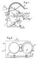
- an operating robot 1 can be moved along a ring bench 2 of a spinning machine. Upon a corresponding signal, it automatically positions itself at a specific spinning position, for example to correct a thread break or to Piecing.
- the robot is stored and guided via guide elements, for example guide rails 3 and 4, which are connected to the spinning machine.
- the robot contains, for example, a supply spool 5 for an auxiliary thread 6, a delivery mechanism 7 for pulling the auxiliary thread 6 from the supply spool 5, and a cutting device 9 for cutting a defined piece of auxiliary thread 6.1 from the auxiliary thread supply.
- Auxiliary devices 12 for example a thread winding device and / or a threading guide, may also be present in the robot 1, which are height-adjustable in the Z direction, for example, by means of a threaded spindle 13 and horizontally displaceable in the X direction, for example, by means of a linear drive 14.
- a thread store in the form of a suction pipe 15 is provided, which is connected by a hose 19 to a vacuum source 20.
- the suction pipe 15 is designed to receive a thread section of a certain length.
- the mouth 16 of the suction pipe 15 can be moved three-dimensionally under the influence of a program-controlled control 50, as is indicated by a servo axis 22 shown schematically in FIG. 1.
- the controller 50 can be designed, for example, as an autonomous robot controller in the form of a processor-equipped programmable control device which ensures automatic operation.
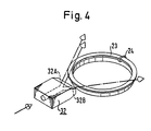
- the threading guide 12 is provided with a holder 26 for further components.
- a controllably rotatable ring 27 is mounted on the underside of the holder 26.
- the ring 27 is connected to a controllable drive 34.
- the ring 27 is provided with a passage 29.
- the bushing 29 is dimensioned such that the ring 27 can be pushed laterally over the thread tube 40 or over the thread body. However, the ring can also be closed and can be guided axially on or around the yarn tube 40.
- the entire holder 26 can be moved under the action of the drive 14 in the X direction e.g. move linearly towards the sleeve 40 between the ring bank 3 and the thread balloon ring 41 and slide with the ring opening 29 over the sleeve until the ring 27 is coaxial with the axis of rotation of the sleeve 40.
- Activation of the drive 34 causes the ring 27 to rotate a defined distance along the spinning ring 23.
- a small brush 31 is placed on the underside of the ring 27, which is used to move the rotor along the circumference of the ring 27, for example to temporarily keep the rotor out of a certain area of the ring, or also to hold the rotor during that described later Threading process to slide over the thread.
- one or more blowing nozzles 32 can be attached to the holder 26, which are provided with an air supply and can be activated in a controlled manner. They direct their blowing jet approximately tangentially to the spinning ring 23 in order to temporarily fix the rotor 24 on the opposite side of the spinning ring 23 when the compressed air is activated.
- two blowing nozzles 32A and 32B act on the spinning ring 23 in different directions of rotation.
- An air blast blows the runner outside the working area of the thread guide 25, while a time-controlled counter air blast positions the runner on the opposite side of the threading device.
- a slide 28 is attached to the holder 26 and can be displaced in the X direction under the influence of a drive 37, for example a pneumatic drive.
- the slide sits on the holder 26 off-center so that its main axis leads into the peripheral region of the sleeve 40 according to FIG. 3, preferably approximately tangentially to the spinning ring 23, so that its tip can be easily positioned over the upper sliding surface of the spinning ring 23.
- the slider 28 serves for the exact positioning of the thread during the threading into the runner described later by pushing the runner onto the thread.
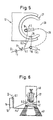
- This is done by activating the delivery mechanism 7 with a specific positioning of the thread store 15, e.g. in position P.1 according to Fig. 5.
- the delivery mechanism 7 is switched off as soon as the desired length of auxiliary thread is in the tube of the thread store 15, e.g. when the auxiliary thread start 6.3 reaches a thread sensor 36 at the rear area of the thread store 15.
- the thread store 15, in the example its mouth 16 can be manipulated three-dimensionally.
- the mouth 16 of the thread store 15 makes a pendulum movement in the inner region of a winding ring 27, for example along the one in FIG 5 indicated path 39 in position P.2.
- the auxiliary thread is placed on a clamping device 35 on the underside of the winding ring 27.
- the mouth 16 of the thread store 15 is then moved back again, around the clamping device 35, into the starting position P.1, the auxiliary thread 6 being clamped in by the clamping device.
- the cutting device 9 separates the auxiliary thread 6 from the feed, so that a finite auxiliary thread piece 6.1 of a defined length is produced.
- this known auxiliary thread length is used, as a result of which various process steps can be better planned in advance and involve fewer uncertainties in the execution of the control programs.
- the auxiliary thread start 6.3 is still in the position of the sensor 36 within the thread store 15.
- the thread is held in the thread store 15 by the suction effect with a slight pull relative to the clamping pin 35.
- the controlled guidance of the auxiliary thread elastically retained in the thread store now takes place.
- the mouth 16 of the thread store 15 with the auxiliary thread piece is now servo-controlled in a lower unwinding position P.4, e.g. performed within the range of the ring bench movement, as shown schematically in Fig. 6.
- the ring 27 is caused to rotate a defined number of times, so that it winds the auxiliary thread end 6.2 held on the clamping device 35 around the sleeve 40 or around its package 43. During this winding process, the auxiliary thread is increasingly pulled out of the elastic retaining thread store 15.
- the sleeve 40 After taking over a certain length of auxiliary thread from the thread store 15, the sleeve 40 is braked to a standstill by means of a spindle brake, so that on the one hand a remaining auxiliary thread length is guaranteed in the thread store 15 and on the other hand the wound end of the auxiliary thread 6.2 cannot be pulled off the package, e.g. in a subsequent threading process.
- auxiliary thread start and end are held by components, the positions of which are clearly determined.
- the auxiliary thread which is thus elastically clamped between two "grippers", can be manipulated three-dimensionally in this way, so that the winding location on the sleeve 40, furthermore the type of winding formation and also the length of the auxiliary thread to be wound from the operating device, for example can be controlled by program specifications. Under these conditions, winding is ensured with a high degree of reliability.
- the winding process is controlled with the help of the thread storage device in a clearly defined sequence of movements, which is no longer influenced by coincidences, as was the case, for example, when blowing a free auxiliary thread end onto the package according to the prior art.
- the operating robot 1 can feed the auxiliary thread start 6.3 from the thread store 15 to the spinning station or the various thread guide elements, thread it into thread guide elements and finally attach it to the running fiber stream.
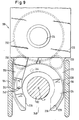
- a corresponding example for threading is shown below in connection with the schematic representation in FIG. 3.
- the sleeve 40 is taken by suitable measures, for example by actuating a spin that is not shown in detail in the figures del brake, braked to a standstill. Now the holder 26 is moved in the above-mentioned manner in the X direction towards the sleeve 40 by activation of the drive 14 and pushed with its opening 29 over the sleeve 40, so that the ring 27 is now coaxial with the sleeve 40.
- the ring 27 and with it the brush 31 are rotated around the sleeve 40 to such an extent that the brush 31 pushes the rotor 24 out of the working area of the slide 28. Thereafter, the holder 26 with the slide 28 located thereon is pushed back into the starting position outside the sleeve 40.
- the blowing nozzles 32 can also be activated for the same purpose instead of the rotary drive.
- the slide 28 is extended, for example by the slide drive 37, into the working position according to FIG. 3, just above the effective area of the now free spinning ring 23.
- the mouth of the suction pipe 15 assumes position A according to FIG. 3.
- the slider 28 engages in the thread piece 6.1.
- the notch 25 is designed and adapted to the surface of the spinning ring in such a way that it holds the thread in the respective position on the one hand and protects it on the other hand, so that the brush 31 does not damage, strip or take away the thread when it moves the rotor 24 can.
- the suction pipe 15 is guided with the thread piece 6.1 over the slide 28 and lowered with its mouth 16 into a position B which is lower than that of the slide 28.
- the tensioned thread piece 6.1 is located at a certain radial distance from the spinning ring 23. The in this way, part of the thread 6.1 clamped between the notch 25 and the mouth 16 of the suction pipe 15 is thus directed obliquely downwards.
- the thread 6 is pulled out of the elastically restraining suction pipe 15, if necessary, so that it remains taut throughout the entire course of movement.
- the suction pipe 15 is now moved into the position C, so that the thread 6.1 is tangent to the spinning ring 23 and still runs downwards from the notch 25 to the mouth 16 of the suction pipe 15.
- the tangential direction is inclined by an angle "alpha" with respect to the plane of the spinning ring 23, as indicated in FIG. 3.
- the value of "alpha" can be approximately 10 degrees.
- the holder 26 or the threading guide 12 is moved to the sleeve 40 by the drive 40, so that the ring 27 is again coaxial with the spinning ring 23 and the sleeve 40.
- the Z position is selected in a program-controlled manner such that the threading guide 12 is coupled to the holder 26 on the ring bench 3 according to FIG. 1, so that the holder 26 follows the lifting movements of the ring bench 3.
- the brush 31 on the spinning ring 23 is rotated clockwise in the example shown in FIG. 3, whereby it pushes the rotor 24 over the thread piece 6.1 lying obliquely downwards on the spinning ring 23 and thus the actual threading process of the thread in takes the runner.
- the slide 28 and its holder 26 are then retracted into their starting positions. The entire device is uncoupled from the moving ring bench 3.
- the operating robot 1 can then be used to thread the part of the thread piece 6.1 remaining in the suction pipe 15 into corresponding thread-guiding elements in a similar manner by corresponding program-controlled manipulations. Finally, the thread start 6.3 is attached to the current fiber stream. This last step is no longer part of the actual threading and is not described further here.
- the suction pipe 15 acts as a thread store in the context described. It brings about an elastic retention of the thread against the tensile force emanating from the braked sleeve 40.
- the thread storage device does not have to be designed as a suction tube, but it can also have any other design that is suitable for the elastically yielding retention of a thread piece.
- the thread to be threaded is held by components, the positions of which are clearly determined during each phase of the process sequence.
- the threading is thus controlled in a clearly defined movement sequence, which is no longer influenced by randomness and uncertainties, as was the case with known proposed solutions according to the prior art.
- the manipulable thread store achieves significantly improved reliability as a prerequisite for a fully automatic process sequence.
- the described method steps are triggered and coordinated by a central process control, in the example by a processor-equipped programmable control device, which is housed in the operating robot and ensures automatic operation.
- Certain sub-processes such as synchronization with processes on the spinning machine or the triggering of machine-specific spindle brakes, are coordinated and controlled via interfaces to the machine control.
- sequence control can also be implemented.
- the sequence of the method steps described is preferably contained in a program which, in conjunction with a process control, initiates the automatic execution of the method steps, for example using standardized computers.
- the manipulable thread store is particularly advantageous when the winding, threading and attachment process is carried out in combination.
- the thread storage device can in principle only be used for threading or for threading with subsequent attachment, without prior winding. In these cases, too, the advantages mentioned, which result from the precisely controllable thread manipulation, have a positive effect.
- the thread store 15 is part of the operating robot 1 and is designed to store an auxiliary thread piece from an auxiliary thread supply carried along, there are particular advantages for monitoring the auxiliary thread supply.
- the presence of the auxiliary thread can be arranged by arranging an auxiliary thread sensor 52 according to FIG. 1 Monitor gear of the delivery plant 7 within the operating robot 1. If the auxiliary thread is missing, the operating robot is put out of operation with regard to its subroutines "thread break repair or spinning" or “threading the auxiliary thread". This operating state is signaled to the outside by suitable optical signaling devices and / or signal paths to a computer or a signal processing device 50.
- the operating robot in the absence of the auxiliary thread, is moved to a predetermined position, e.g. at the end of the ring spinning machine, moved into a waiting position to wait for the auxiliary thread supply to be completed.
- a predetermined position e.g. at the end of the ring spinning machine
- the operator robot does not correct any further thread breaks during the journey to the waiting position.
- the operating robot is not automatically restarted until the auxiliary thread supply has been replaced.
- the auxiliary thread supply can be supplemented manually by operating personnel or automatically by a suitable auxiliary device.
- a further exemplary embodiment for determining the auxiliary thread consists in the arrangement of sensors of any type, for example optical or mechanical scanning sensors 54, which scan the diameter of the auxiliary thread package. If a given dimension for the diameter falls below, the above-mentioned state occurs, but in this If the auxiliary thread supply can be added before it is completely exhausted.
- the length of the auxiliary thread supply is measured and known.
- the thread quantity emitted by the auxiliary bobbin is continuously measured and recorded in a connected process computer in order to continuously calculate the remaining quantity therefrom and to initiate the refill measures described above when the value falls below a predetermined threshold.
- the thread storage device 15 is shown in the examples as a suction tube, it can also have a different design, which is suitable for the elastically yielding retention of a piece of thread and for program-controlled spatial manipulation.
- the freely manipulable thread store is also advantageous for other thread manipulations, for example when threading through direct detection of the spinning thread by the bobbin.
- the spinning thread can also be safely and securely threaded directly into thread guide elements of the spinning machine by manipulating the thread store.
- FIGS. 7 to 20 In order to more clearly illustrate the threading process described above, a detailed description is given below with reference to FIGS. 7 to 20. For the sake of simplicity, other reference symbols are used here, although many parts or method steps described below have already been explained in connection with FIGS. 1 to 6. The numbering used in FIGS. 7 to 20 also allows a clear assignment to the corresponding priority application.
- reference numeral 100 indicates the chassis of the operating robot for operating spinning positions on a ring spinning machine.
- Each such spinning station contains an assembly 101 for imparting twist and for unwinding the yarn; this unit 101 here comprises a spindle 102, a spinning ring 106 carried by a ring bench 104 and a rotor (not shown) mounted on the spinning ring 106.
- the chassis 100 runs along a machine side on bicycles 105 guided by a guide rail 103.
- a support arm 107 carries a guide roller 109 which runs in a further guide rail 113 carried by the machine and holds the chassis 100 in a predetermined position with respect to the machine.
- the guide rail 113 is mounted on the machine frame (not shown) by a suitable holder 115.
- the operating robot comprises both an attaching device 150, which should be explained in more detail below, and a handling device 124, which is described in detail in the aforementioned sister application and therefore only in this application has been treated sketchily.
- the handling device 124 namely comprises a suction tube 134 for receiving a predetermined thread length (not shown) with a mouth part 136 and a connection 138 to a vacuum source 132 carried by the chassis 100.
- the mouth part 136 of the suction tube 134 can be indicated by a controllable articulation system 140 (only schematically indicated) ) can be moved relative to the chassis 100.
- the mouth part 136 is brought to a delivery point 128 for receiving thread 144 from a thread supply 122 carried by the chassis 100.
- the thread is delivered from a delivery mechanism 126 mounted on the chassis 100 via the delivery point 128 into the suction pipe 134 until this pipe has taken up a predetermined thread length.
- the articulation system 140 of the handling device is then actuated in order to establish a “connection” with the winding device 150. This "connection" will be described in more detail below and has also been dealt with in the aforementioned Swiss patent application No. 4852/88.
- the thread 144 is separated between the delivery mechanism 126 and the winding device 150 (separating means not shown), so that the thread length picked up can now be manipulated by the handling device 124 and winding device 150 independently of the supply 122 in accordance with a predetermined control program .
- FIG. 7 The schematic representation in FIG. 7 is favorable for identifying the different parts in that these parts have been shown far apart.
- the illustration is unrealistic in that the mouth part 136 and the winding device 150 are sealed must be guided side by side after they have entered a single spinning station via the "surface line" 117 of the machine.
- both the handling device 124 and the winding device 150 can be retracted into the chassis 100, so that the robot has a clear distance L from the surface line 117 when driving along the machine (with the exception of the guide system 107, 109).
- the winding device 150 must be movable in a direction (the “X direction”) transverse to the vertical longitudinal axis of the spindle 102.
- the device must be movable in one direction (the "Z direction”) along the spindle axis, as is clear from the description below.
- FIG. 8 schematically shows a drive system for moving the winding device 150 both in the X and in the Z direction.
- the device 150 is mounted on the piston rod 200 of a piston-cylinder unit 202.
- a suitable source not shown
- the piston is pressed from its retracted position to the right according to the side view in FIG. 8 against the spindle 102.
- This movement is limited by a suitable stop (not shown) in order to hold the winding device 150 in a suitable, still to be described working position relative to the spindle 102.
- the device 150 will return from its working position to a retracted position.
- the unit 202 is mounted on a slide 186, which in turn is mounted on a threaded spindle 196 via a carrier 184.
- Spindle 196 is in Chassis 100 is mounted vertically (ie essentially parallel to the longitudinal axis of spindle 102) and coupled at one end to a drive motor 204.
- the drive motor 204 is controlled by a microprocessor with suitable programming (software); However, in order to depict the control method visually, the control program is indicated schematically by control loops or a control box. In a first state, the motor 204 is controlled by a sensor 206 via a first controller 208, in a second state by the same sensor 206 via a second controller 210 and in a third state by a controller 212.
- the sensor 206 responds to the position of the ring bench 104 in order to position the slide 186 with the winding device 150 accordingly in the Z direction.
- the signal emitted by the sensor 206 is delivered to the first controller 208 via the switching means 214 while the robot is traveling and is delivered by switching from the switching means 214 to the second controller 210 during a certain phase of the operating work (as will be explained in more detail below).
- the controller 212 controls the drive motor 204 when the position of the carriage 186 needs to be controlled independently of the ring bench position, e.g. when picking up the auxiliary thread at delivery point 128 (FIG. 7).
- the individual spinning positions of a ring spinning machine are shielded from one another in the longitudinal direction of the machine by so-called separators 194.
- the working head shown in FIG. 9 comprises a carrier section 220 which remains outside the spinning station space defined by the separators 194 and a C-shaped part 222 which projects into the space of the spinning station to be operated in all working positions of the winding device 150.
- the C-shaped part 222 surrounds (in part) a C-shaped operating runner 224 and forms a guide in the form of a track 226 for the operating runner.
- These two C-shaped parts 222, 224 have a common axis P, which in all working positions of the winding device is aligned with the longitudinal axis of the spindle 102 or in the vicinity of the spindle axis and approximately parallel to it.
- the operator runner 224 is rotatable in the track 226 about the axis P relative to the C-shaped part 222.
- the operating rotor 224 is provided with a ring gear 228 (indicated by dashed lines) and this ring gear meshes with two toothed rollers 230.
- the rollers 230 in turn mesh with the ring gear a drive pulley 232 which is rotatably mounted in the carrier section 220 and by a suitable one Drive motor 234 can be rotated.
- the opening 236 of the operating rotor 224 with the opening must be 238 of the C-shaped Part 222 be aligned.
- the operator runner 224 is therefore provided with a suitable marking (not shown) and the C-shaped part 222 carries a sensor 240 which reacts to this marking in order for this "ready position" of the operator runner 224 relative to its holder 222 to the controller (not shown) ) for the engine 234.
- the access opening 240 formed thereby is wide enough to receive the spindle 102 and a sleeve 112 carried by it (FIG. 10, not indicated in FIG. 9), but not a cop 116 formed on the sleeve 112 (FIG. 10).
- the feed device 150 must therefore be fed to the spindle 102 at a height (along the spindle axis) which lies above the currently highest winding position of the spinning ring 16 (FIG. 10).
- the distance between the transfer rollers 230 in the circumferential direction of the operating rotor 224 is selected such that if one roller 230 no longer meshes with the ring gear 228 due to the discontinuity caused by the access opening 240, the transmission of the drive forces from the disk 232 to the others remains Guaranteed roles on the operator runner 224.
- the operating rotor 224 carries two working elements 242, 244.
- the element 242 comprises a pin which runs vertically through a suitable bore in the operating rotor 224 and is provided with a clamping head 246 on the underside of the rotor 224.
- the pin is pushed up by a suitable spring load (not shown) to hold the clamping head 246 in a clamping position contacting the underside of the operator rotor.
- actuating mechanism 248 mounted on the carrier section 220.
- This mechanism includes a rocker arm 250 with a head 252 which is just above the pin when the operator runner 224 is in its ready position ( Figures 9 and 10).
- the head 242 By tilting the lever 250 (e.g. by means of a pneumatic device on the carrier part 220, not shown) in a clockwise direction according to FIG. 10, the head 242 can initially be brought into contact with the pin and then moved on to the pin with the clamping head 246 against the spring load to push down.
- the device 150 is brought near the delivery point 128 by the actuation of the motor 204 (FIG. 8) by the controller 212, the operator runner 224 being held in its ready position in relation to the part 222.
- the actuation of the motor 204 FIG. 8
- the operator runner 224 By suitable movements of the mouth part 136 (see in this connection the Swiss patent application No. 4852/88) and the opening of the clamping device by the actuating mechanism 248, an auxiliary thread extending between the mouth part 136 and the delivery point 128 is moved into the clamping device and by releasing the Mechanism 248 is connected to the operator runner 224 by clamping.
- the winding device 150 and the handling device 124 together form an attachment unit, which can first connect the stored auxiliary thread to the winding unit 101, then thread it with the thread guide elements of the spinning station and finally with one of a drafting system (not shown). supplied roving.
- the second working element 244 is a flexible element e.g. a brush to strip the upward surface of the ring 106. This element is used to move the rotor on the spinning ring 106 as should be described in more detail below.
- the carriage 186 is moved upward by actuating the motor 204 in order to move the device 150 into a predetermined position with respect to the currently uppermost turns W (FIG 10) to bring the cop.
- the highest position of the ring bench 104 is sensed and stored while the robot is moving, so that the controller 208 is able to bring the slide 186 immediately to the appropriate working height (along the threaded spindle 196) after leaving the delivery point 128 .
- the unit 202 is actuated to move the device 150 against the spindle 102 into the first working position (FIG. 10).
- the clamping plane formed by the clamping head 246 and the operating rotor 224 lies above the uppermost windings W of the cop at a predetermined distance (not shown).
- a thread break can already occur in the first phase of the bobbin formation, so that the first working position would then lie much further down relative to the spindle 102 and sleeve 112. If the thread breaks during a doffing process, it can even happen that the the corresponding spinning station is not started at all, so that the auxiliary thread must be connected to the "bare" sleeve.
- the correct first job can still be determined in relation to the uppermost position of the ring bench 104 during its traversing movement.
- the operating runner 224 is held in its standby position during this infeed movement, so that the access opening 240 for receiving the spindle 102 and sleeve 112 is present.
- the mouth part 136 is brought to a corresponding work station, so that the mouth M (FIG. 1 lies below the clamping plane at a distance to be described.
- the auxiliary thread F extends between the mouth M and the clamping head 246 with a vertical distance between the Mouth M and inclination corresponding to the clamping plane (solid line in FIG. 10).
- the motor 234 (FIG. 9) is now actuated in order to rotate the operator runner 224 in its career 226 (FIG. 9) clockwise according to FIG. 6 about the axis P.
- This rotation initially shortens the distance between the mouth M and the clamping head 246, the "unnecessary" length of the thread F being absorbed by the suction in the tube 134.
- the thread F is pulled out of the suction tube 134 again by further rotations of the operating rotor 224 with the clamping head 246 and placed on the sleeve 112 or the outer turns of the cop 116 (FIG. 12).
- the first turn of the thread F runs down a spiral around the sleeve 112 and cop 116 until the thread F lies in a horizontal plane containing the mouth M (dashed line in FIG. 10).
- some connecting turns V (FIG. 10) are formed in this plane.
- the aforementioned distance between the mouth M and the clamping plane is selected such that, if a cop 116 is present at all, these first connecting windings V lie below the uppermost winding W of the cop.
- the work site of the mouth M is therefore below the uppermost position of the ring bench 104 during its traversing movement, so that this work site must be kept outside the movement area of the ring bench 104 (see FIG. 11).
- the first turns V are formed by rotating the operating rotor 224 both with respect to the spindle 102 or sleeve 112 and with respect to the C-shaped holder 222.
- the thread F is pulled directly from the suction pipe 134 by the rotation of the operating rotor 224.
- the rope effect between the thread F and the cop 116 becomes so great that a weaker thread F would break between the clamping head 246 and the turns V when the spindle 102 was stationary.
- the spindle 102 is released from its drive (not shown) during the winding process, so that it can currently be freely rotated (see in this connection the Swiss patent application No. 4852/88) .
- the mouth part 136 is also moved upwards in order to wind further binding turns B (FIG. 13) on the sleeve 112, these turns B securely binding the above-mentioned piece of thread to the sleeve 112.
- the turns B also serve another purpose, but this only becomes clear when a later phase of the process is explained and is therefore only discussed later in this description.
- the spindle 102 In order to form these last bindings B, the spindle 102 must still be able to rotate freely and the thread F must remain intact between the bindings formed on the sleeve and the clamping head 246. However, after this second winding phase has been completed, the spindle 102 is braked by suitable means (not shown) while the operator runner 224 continues to run. The thread F is thereby pulled out of the clamping head 246 and forms a free end FA (FIG. 14).
- the mouth part 136 is brought from its second working position (FIG. 13 and FIG. 15, solid lines) to a third working position on the other side of the spindle 102 and winding device (dashed lines in FIG. 15) .
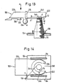
- a slide 260 carried by the carriage 186 is now moved from a retracted position (FIGS. 10 and 13) to an advanced position (FIGS. 14 and 17 to 20) by a suitable actuating means (for example by a pneumatic piston and cylinder unit, not shown) .
- a V-shaped guide part 262 (FIGS. 10, 13 and 19) engages in the free thread length between the sleeve 112 and the mouth part 136.
- Slider 260 is advanced so far that the thread length mentioned is deflected by the guide part 262 and finally held in a predetermined position becomes. This position is determined by a suitable end stop (not shown) for the slide 260.
- the mouth part 136 is now moved upwards and then brought back onto the first side of the spindle 102 and angling device 150 (FIG. 17).
- the mouth M is moved downwards so that the thread F runs underneath the winding device 150 and between the mouth M and the edge of a guide surface FF (FIG. 15) on the uppermost surface of the slide 260 a predetermined inclination upwards (in FIG 12 not visible).
- the slider 260 is provided with a constriction 261 (FIG. 15) in order to guide the thread on the surface FF.
- the position of the mouth part 136 is now selected so far away from the ring bench 104 that the thread F lies outside the movement space of the ring 106 (FIG. 17).
- the winding device 150 is now shifted back into its second working position (FIG. 18), after which the threading preparation phase is completed.
- FIG. 16 schematically shows the cop 116, the yarn G during normal spinning and the runner 108, the direction of rotation of the cop being indicated by the arrow R. This direction of rotation is also indicated by an arrow on the spindle 102 in FIG. 15, although the spindle may not actually rotate during the preparation phase.
- certain geometrical relationships must prevail when threading the auxiliary thread F with the rotor 108.
- the thread length to be threaded must extend from the left to the right from the slide 260 to the mouth part 136.
- this thread length must have a slight inclination from above on the slide 260 downward at the mouth 136.
- This inclination ⁇ is indicated in FIG. 18 (in this figure part of the cop 116 has been "cut away” to show the guide head of the slider 260).
- the runner 108 has to be pushed onto the thread F by moving along the spin ring 106 in a clockwise direction according to FIG.
- the auxiliary thread length extending between the runner 108 and the mouth part 136 can then be pulled upwards in order to correspond to the position of the thread length G (FIG. 16).
- the conditions previously described depend on the direction of rotation of the spindle 102, which in turn depends on the yarn rotation (S or Z rotation).
- the conditions described are adapted for a yarn with an S twist, which corresponds to the products of most spinning mills.
- the slide 260 When producing yarn with a Z twist, the slide 260 would have to be laid on the other side of the spindle 102 (again in the direction of the arrow L, viewed in FIGS. 10, 12 and 13) and the thread length to be threaded would have to be from the right to the left of the slide 260 extend to the mouth part 136.
- the device 150 In order to produce the conditions already described, the device 150 must in any case be moved into its retracted position, at least in order to enable the orifice part 136 to be moved after the thread F has been brought into contact with the guide part 262 of the slide 260. For the winding it does not matter whether the mouth part 136 is placed to the left or to the right (viewed in the direction of the arrow L) relative to the winding device 150.
- the position of the clamping point 242 in the circumferential direction of the operating rotor 224 also does not play a major role in this regard.
- the clamping point 242 can preferably be brought as close as possible to the separating means (not shown) for separating the thread between the clamping point and the delivery mechanism 126 (FIG. 7) in order to avoid a long thread end which depends on the clamping point.
- the switching means 214 is switched to the controller 210 (FIG. 9) and the motor 204 is activated in order to move the slide 186 down the threaded spindle 196 until the sensor 206 has the ring bench 104 "finds".
- the mouth part 136 is moved accordingly, so that the already prepared conditions are maintained.
- the sensor 206 scans contactlessly for the ring bank 104.
- the sensor 206 After the sensor 206 has "found" the ring bench 104, the sensor sends a signal to the controller 210 to keep the motor in continuous operation, so that the carriage 186 together with the winding device 150 follows the movements of the ring bench 104.
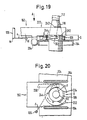
- the clamping plane of the operating rotor 224 is obtained at a predetermined distance S (FIG. 19) above the upward surface of the ring bench 104.
- the second working element (the brush) 244 is held in contact with the upwardly facing surface of the ring 106.
- the vertical movements of the ring bench 104 are followed without contact as previously indicated and therefore without loading the ring bench drive (not shown).
- the positioning of the winding device 150 in the X direction (FIG. 7) to ensure that the brush 244 is in contact with the spinning ring 106 is, however, effected by a feeler roller 264 mounted on the device 150. This touch does not burden the ring bench drive.
- FIG. 20 shows the last movement of the threading process, the operating runner 224 being rotated again clockwise around the axis P, thereby also moving the runner 108 (not visible in FIG. 20) clockwise along the spinning ring 106 along the thread length between the mouth part 136 and to move the slider 260.
- the mouth part 136 is to be brought in the direction of the ring bank 104 into the position shown in FIG. 20 and the thread piece to be threaded is placed close to the spinning ring 106, the inclination ⁇ (FIG. 20) being maintained.
- the runner 108 is at a suitable location opposite the spinning ring 106 so that the brush 244 can push it in the desired direction.
- This is actually preferably the first step in the whole process and is even carried out before the auxiliary thread length is fetched.
- the winding device is continuously held along its "working height" along the threaded spindle 196 by the control system shown in FIG.
- the sensor 206 senses the upper reversal point of the ring bench movement while the robot is traveling and uses it to adjust the position of the slide 186.
- the device When a thread break is detected or after positioning at the spinning position to be operated, the device can be immediately delivered to the spindle 102 in question (in the first working position, FIG. 10) and the carriage 186 can then be moved down to the device Dock ring ring 104 (in the third working position, Figure 19 - as already described for threading). The operator runner can then be actuated to place the runner in a predetermined position (eg, position X in Figure 20) where it will neither interfere with nor prepare for threading.
- a predetermined position eg, position X in Figure 20
- the motor 204 can then be started again in order to uncouple the device from the ring bench and return it to the first working position (FIG. 10), so that it can be pulled back into the robot for picking up the auxiliary thread from the delivery point 28.
- the motor 204 is controlled independently of the position of the ring bench 104 in order to e.g. to the lower end of the spindle 196 and thereby in the vicinity of the delivery point 28.
- the "working height" (the height of the first working position along the spindle 102) is saved, so that after the auxiliary thread has been picked up, the attachment unit (winding device 150 and handling device 124) can be brought back to the working height immediately. The procedure already described can then be carried out.
- the movement of the operating rotor 224, indicated in FIG. 20, encompasses one full revolution of this organ, so that the brush 244 runs over the thread length extending between the sleeve 112 and the slide 260.
- Contact between the bust 244 and the thread length F should, however, be avoided if possible, since otherwise the thread run could be destroyed.
- the guide part 262 of the slide 260 is therefore provided with a screen piece 266 (best seen in FIGS. 15 and 17), which in the threading position (FIG. 18) lies directly above a section of the spinning ring 106 and the thread F from the brush 244 during the shields the aforementioned threading revolution of the operating rotor 224.
- the first sister registration shows that the handling device 124 is also carried by the slide 186.
- the thread F (after the slide 108 has been pushed on) can be moved upwards by the handling device 124.
- the auxiliary thread F remains threaded with the rotor 108 and is pulled out of the suction pipe 134.
- a thread length also remains between the runner 108 and the cop 116.
- the tensile force that is exerted on the auxiliary thread F acts in the opposite direction to the tensile force that is exerted during normal spinning (starting from the cop 116). If the auxiliary thread F now runs in a substantially horizontal position from the runner 108 to the cop 116, the forces exerted by the auxiliary thread F on the runner 108 could under certain circumstances be sufficient to move the runner along the spinning ring 106, in that for the Spinning normal direction (clockwise in Figure 15). However, since the spindle 102 was still stationary at this time, this movement of the runner would mean the pulling of thread windings from the bobbin, which could lead to a further thread break when attaching for various reasons.
- the upper turns during winding ie the binding turns B, FIG. 13
- the thread length extending from the windings B to the rotor 108 always has an upward slope as seen away from the rotor 108.
- the of the thread lengths on both sides of the runner on these forces exerted during the further threading phases only partially compensate for one another and give a resultant that raises the runner 108 upwards against the underside of the spinning ring 106 rather than moving the runner along the spinning ring. An unfavorable development of wound binding turns B is avoided.
- connection of the auxiliary thread piece with the yarn carrier finally takes place due to the rotational movement of the one holder in the form of the winding ring with a clamping device around the yarn carrier.
- a connection between the auxiliary thread piece and the thread carrier is achieved at a desired point in time by the action of friction. It is obvious that this principle can also be implemented in other ways.
- the essence of the invention therefore lies in a method for applying an auxiliary thread to a yarn carrier of a spinning machine located at the spinning position, the method being characterized in that an auxiliary thread piece clamped on two sides in holders is placed on the thread carrier and with one of the holders around the thread carrier is looped until the auxiliary thread piece is connected to the yarn carrier by friction.
- this principle can best be achieved when the yarn carrier stands still during the wrap movement, and is preferably also freely rotatable.
- the yarn carrier is first uncoupled from the normal drive of the spinning station and then driven by a separate rotary drive, for example by a drive that is located on the operating device and the sleeve or the spindle, for example, with drives a rubber wheel to rotate by friction.
- the winding ring initially produces a few loose turns around the thread carrier and that the sleeve and therefore the thread carrier is then driven to a separate rotary movement in order to tighten these loose windings and therefore the required friction connection between the auxiliary thread piece and to establish the thread carrier.
- This could be done, for example, in that at the beginning of the wrap the separate drive for the yarn carrier drives the yarn carrier at the same rotational speed as that of the winding ring and then changes the rotational speed of the thread carrier with respect to the winding ring, preferably accelerates, in order to tighten the wraps that have taken place and at the right moment pull the end of the auxiliary thread piece out of the clamping device or release it by releasing the clamping device.
- the separate drive could then be detached from the thread carrier and the process continued, as previously described in detail, until the spinning station produced again.
Landscapes
- Engineering & Computer Science (AREA)
- Mechanical Engineering (AREA)
- Textile Engineering (AREA)
- Spinning Or Twisting Of Yarns (AREA)
- Replacing, Conveying, And Pick-Finding For Filamentary Materials (AREA)
Abstract
Description
Die Erfindung betrifft ein Verfahren und einen Bedienroboter zum Einfädeln eines Fadens von einem an der Spinnstelle einer Spinnmaschine befindlichen Garnträger in Fadenführungs elemente, gemäss den Oberbegriffen der Ansprüche 1 und 4. Unter einem Garnträger wird eine leere Hülse oder eine leere Hülse mit einem angewickelten Hilfsfaden oder eine Hülse mit einem Garnkörper verstanden. Das Verfahren und der Bedienroboter lassen sich z.B. einsetzen zum Einfädeln eines Fadens oder eines Hilfsfadens in den Läufer und andere Fadenführungselemente während des Behebens von Fadenbrüchen beim Spinnvorgang und in Verbindung mit dem robotergestützten Anspinnen bzw. Anwickeln nach dem Doffen auf einer Ringspinnmaschine.The invention relates to a method and an operating robot for threading a thread from a yarn carrier located at the spinning position of a spinning machine in thread guide elements, according to the preambles of claims 1 and 4. Under a yarn carrier is an empty tube or an empty tube with a wound auxiliary thread or understood a sleeve with a package. The process and the operating robot can be e.g. use for threading a thread or an auxiliary thread into the rotor and other thread guide elements during the repair of thread breaks during the spinning process and in connection with the robot-assisted piecing or winding after doffing on a ring spinning machine.
Es sind aus der Patentliteratur einige Bedienungsroboter bekannt, welche zum Beheben von Fadenbrüchen an einer Ringspinnmaschine konzipiert sind. Beispiele sind in US-PS 3 445 997, DAS 1 760 259, DAS 2 501 338 und US-PS 3 628 320 zu finden. Bei allen solchen Robotern ist es notwendig, gewisse Arbeiten an der Spindel der Verarbeitungsposition (Spinnstelle) auszuführen. Solche Arbeiten umfassen z.B. das Fadenende auf dem von der Spindel getragenen Kops (der Fadenspule) zu finden oder einen Hilfsfaden an dem Kops anzuwickeln, einen Faden mit dem Läufer einzufädeln usw. Danach wird das freie Ende des Fadens mit dem aus dem Streckwerk der Spinnmaschine kommenden Faserstrom in Verbindung gebracht und an diesem angesetzt.Some operating robots are known from the patent literature, which are designed to correct thread breaks on a ring spinning machine. Examples are found in U.S. Patent 3,445,997, DAS 1,760,259, DAS 2,501,338 and U.S. Patent 3,628,320. With all such robots, it is necessary to carry out certain work on the spindle of the processing position (spinning station). Such work includes, for example, finding the end of the thread on the bobbin (the bobbin) carried by the spindle or winding an auxiliary thread on the bobbin, threading a thread with the runner, etc. Then the free one The end of the thread is connected to the fiber stream coming from the drafting unit of the spinning machine and attached to it.
In allen bekannten Lösungen wird nur von der "Vorderseite" gearbeitet, d.h. der Roboter läuft normalerweise einer Maschinenseite entlang, welche in bezug auf die entsprechende Spinnstellenreihe als die "Vorderseite" bezeichnet werden kann. Wenn der Roboter Arbeiten an einer bestimmten Stelle zu verrichten hat, positioniert er zuerst an dieser Stelle und reicht dann Arbeitselemente von dieser Vorderseite in die Spinnstelle hinein. Unter solchen Umständen ist es fast unmöglich, gesteuerte Bewegungen der Arbeitselemente um den ganzen Umfang der Spindel auszuführen.All known solutions only work from the "front", i.e. the robot normally runs along a machine side, which can be referred to as the "front" with respect to the corresponding row of spinning positions. If the robot has to do work at a certain point, it first positions at this point and then extends working elements from this front into the spinning position. In such circumstances, it is almost impossible to make controlled movements of the working elements around the entire circumference of the spindle.
Zum Einfädeln des Garns in den Läufer sind verschiedene Verfahren und Vorrichtungen bekannt, z.B. wie in CH-PS 515'172 dargestellt, unter Verwendung eines Luftstromes, mit welchem der Läufer auf dem Spinnring in eine bestimmte Stellung gebracht wird, worauf er auf das vom Kops über die Läuferbahn des Ringes herangeführte Garn aufgeschoben wird. Dieses an sich bekannte Prinzip konnte jedoch in der Praxis nicht mit einer Zuverlässigkeit realisiert werden, welche heutigen Anforderungen genügt, so dass die Fachwelt eine Vielzahl weiterer Vorschläge zum Einfädeln eines Fadens in den Läufer einer Spinnmaschine verfolgte.Various methods and devices are known for threading the yarn into the runner, e.g. as shown in CH-PS 515'172, using an air stream with which the runner is brought into a certain position on the spinning ring, whereupon it is pushed onto the yarn brought in by the cop over the runner path of the ring. In practice, however, this principle, which is known per se, could not be implemented with a reliability that meets today's requirements, so that the experts followed a number of other suggestions for threading a thread into the rotor of a spinning machine.
Es ist Aufgabe der vorliegenden Erfindung, das erwähnte Einfädelprinzip dahingehend weiterzuentwickeln, dass es sich für den praktischen Einsatz in Verbindung mit einem Bedienroboter eignet.It is an object of the present invention to further develop the threading principle mentioned to the extent that it is suitable for practical use in connection with an operating robot.
Diese Aufgabe wird erfindungsgemäss durch die kennzeichnenden Merkmale der Ansprüche 1 und 4 gelöst. Der Vorteil dieser Lösung liegt in der hohen Präzision der Fadenführung, welche im wesentlichen ein Ergebnis der gesteuerten, genau vorgegebenen Bewegungsabläufe bei der Manipulation des Fadens ist, so dass das Einfädeln mit höchster Zuverlässigkeit erfolgt, z.B. im Anschluss an einen automatisch gesteuerten Anwickelvorgang, in dessen Verlauf ein zweiseitig eingespanntes Fadenstück mit hoher Zuverlässigkeit an eine beliebig zu bestimmende Stelle auf dem Garnträger angewickelt wird. Da dieses Anwickeln auch auf leerer Hülse mit gleich hoher Zuverlässigkeit erfolgen kann, lässt sich das daran anschliessende Einfädelverfahren nicht nur nach Fadenbrüchen, sondern auch nach dem Doffen oder nach einem Partienwechsel bzw. bei Inbetriebnahme der Spinnmaschine anwenden. Alle diese Vorgänge laufen bei Anwendung des hier vorgeschlagenen Verfahrens mit Unterstützung eines Bedienroboters vollautomatisch ab. Bedienungspersonal ist für die eigentlichen Arbeitsabläufe nicht mehr erforderlich.According to the invention, this object is achieved by the characterizing features of claims 1 and 4. The advantage of this solution lies in the high precision of the thread guide, which is essentially a result of the controlled, precisely specified movement sequences during the manipulation of the thread, so that threading takes place with the greatest reliability, e.g. following an automatically controlled winding process, in the course of which a piece of thread clamped on both sides is wound with high reliability to any location on the thread carrier that can be determined as desired. Since this winding can also be carried out on an empty tube with the same high level of reliability, the subsequent threading process can be used not only after thread breaks, but also after doffing or after a batch change or when the spinning machine is started up. All of these processes run fully automatically when the method proposed here is supported by an operating robot. Operating personnel are no longer required for the actual work processes.
Insgesamt ergibt sich mit den hier dargelegten Massnahmen ein bisher unerreicht hoher Erfolg beim Einfädeln sowie ein breiteres Einsatzspektrum beim Anfahren der Maschine, beim Fadenbruchbeheben, beim Doffen und beim Partienwechsel, wobei die verwendeten Hilfsmittel von einfachem Aufbau sind und sich besonders gut in ein bereits vorgeschlagenes Verfahren zum vollautomatischen Anwickeln eines Fadens, z.B. eines Hilfsfadens, einfügen.Overall, the measures outlined here result in unprecedented success in threading and a broader range of uses when starting up the machine, removing threads, doffing and changing lots, with the tools used being simple and particularly well suited to an already proposed method for fully automatic winding of a thread, eg an auxiliary thread.
Bei Auftreten einer Störung stellt ein Bedienungsroboter gemäss den bisher bekannten Verfahren die von der Störung betroffende Spinnstelle mittels einer geeigneten Massnahme, z.B. durch Unterbrechen der Lunte, ausser Betrieb. Die Störungsursache wird dann durch das Bedienungspersonal zu einem geeigneten Zeitpunkt behoben. Unbesetzte Arbeitsschichten, z.B. in der Nacht, können zu einem Ausfall eines Teils der Spinnstellen führen, so dass das Produktionsvolumen geringer ist als erwartet, wodurch die Produktionsplanung mit unerwünschten Unsicherheiten belastet ist. Bei Arbeitsbeginn ist zunächst ein beträchtlicher Arbeits- und Zeitaufwand für die Behebung der Störungen aufzuwenden.If a malfunction occurs, an operating robot uses the methods known hitherto to set the spinning station affected by the malfunction by means of a suitable measure, e.g. by interrupting the fuse, out of service. The cause of the fault is then remedied by the operating personnel at a suitable time. Unoccupied working shifts, e.g. at night, can lead to a failure of some of the spinning stations, so that the production volume is lower than expected, which means that production planning is burdened with undesirable uncertainties. When starting work, a considerable amount of work and time is required to remedy the malfunctions.
Als häufigste Störungsursache kommt in der Praxis ausser Fadenbruch das Ende des Hilfsfadenvorrats in Betracht. Im allgemeinen wird der Hilfsfadenvorrat als Garnkörper, Kops oder Spule vom Bedienungsroboter mitgeführt. Selbst in automatisierten, bedienerlosen Spinnereianlagen ist es schwierig, den richtigen Zeitpunkt zu erkennen, zu dem der verbrauchte Hilfsfadenvorrat ersetzt werden muss. Auch für das Personal ist das Erkennen des richtigen Zeitpunktes nicht immer einfach, da es durch eine Vielzahl von Aufgaben und Tätigkeiten in Anspruch genommen ist. Besonders erschwerend wirkt sich der Umstand aus, dass bei bekannten Anlagen der Hilfsfadenverbrauch bei jedem einzelnen Vorgang, z.B. beim Beheben von Fadenbrüchen, stark variiert und es sich damit nur schlecht abschätzen lässt, wie weit ein bestimmter Vorrat noch reicht. Wird der Vorrat nicht rechtzeitig ersetzt, laufen automatisch zeitraubende erfolglose Fadenansetzversuche ab, die schliesslich zum endgültigen Stillsetzen der betreffenden Spinnstelle führen. Für das Bedienungspersonal ergibt sich später ein unerwünschter vermehrter Arbeitsaufwand.In practice, apart from thread breakage, the most common cause of failure is the end of the auxiliary thread supply. In general, the supply of auxiliary thread is carried as a package, bobbin or bobbin by the operating robot. Even in automated, unattended spinning plants, it is difficult to recognize the right time at which the used supply of auxiliary thread has to be replaced. Recognizing the right time is also not always easy for the staff, as it is used by a variety of tasks and activities. The fact that in known systems the auxiliary thread consumption varies greatly with each individual process, for example when removing thread breaks, and it is difficult to estimate how far a certain stock will last. If the stock is not replaced in time, time-consuming unsuccessful thread attachment attempts run automatically, which ultimately lead to the final stopping of the spinning station in question. For the operating personnel, there is later an undesirable increased workload.
Ein Bedienungsgerät für Spinnmaschinen, welches einen an den Spinnstellen entlangbewegbaren Schlitten oder Wagen aufweist und selbsttätig gewisse Arbeitsgänge zur Beseitigung von Fadenbrüchen durchführt, ist grundsätzlich aus DE 21 39 881 bekannt. Die Vorrichtung besitzt auch Fühlschalter, um das Vorhandensein des Vorgarns bzw. dessen Bruch anzuzeigen.An operating device for spinning machines, which has a carriage or carriage which can be moved along the spinning positions and which automatically carries out certain operations for eliminating thread breaks, is known in principle from DE 21 39 881. The device also has feeler switches to indicate the presence or break of the roving.
Andererseits ist aus DE 25 01 338 ein Verfahren zum Anblasen eines freien Hilfsfadenendes an eine Aufwickelspule bekannt, bei dem das freie Ende des Hilfsfadens so in einer Speichervorrichtung gespeichert wird, dass es gegenüber der Hilfsfadenspule unter Spannung und damit ohne Durchhang gehalten werden kann. Das Garn des Hilfsfadens soll dadurch seinen Drall behalten, damit sich keine Schlingen bilden. Dabei bleibt der Hilfsfaden solange mit der Vorratsspule verbunden, bis ein genügend langes Stück des Hilfsfadens auf dem Garnkörper aufgewickelt ist. Die dazu erforderliche Hilfsfadenlänge ist nicht bestimmt, sondern von Fall zu Fall verschieden. Das oben erwähnte Problem mit der ungenügenden Abschätzungsmöglichkeit des Hilfsfadenverbrauchs ist demnach durch das bekannte Verfahren nicht gelöst.On the other hand, a method for blowing a free auxiliary thread end onto a take-up spool is known from
Es ist daher eine weitere Aufgabe der vorliegenden Erfindung, ausgehend von den beschriebenen Unzulänglichkeiten, ein Verfahren und eine Vorrichtung zu entwickeln, welche ein gesteuertes Manipulieren eines Fadenendes und bei Verwendung eines Hilfsfadens ein genaues Bestimmen der benötigten Hilfsfadenlänge und damit ein vereinfachtes und vorausschauendes Überwachen und Ersetzen des Hilfsfadenvorrats ermöglichen. Als zusätzliche Aufgabe soll sich die angestrebte Lösung organisch in ein Ringspinnmaschinen-System, z.B. auch unter Verwendung eines Bedienungsroboters einfügen, welches eine einfache und zuverlässige Fadenmanipulation im Bereich zwischen der Spinnstelle und dem Streckwerk an Ringspinnmaschinen ermöglicht.It is therefore a further object of the present invention, based on the shortcomings described, to develop a method and an apparatus which control manipulation of a thread end and, when using an auxiliary thread, an exact determination of the required auxiliary thread length and thus a simplified and predictive monitoring and replacement allow the supply of auxiliary threads. As an additional task, the desired solution should fit organically into a ring spinning machine system, for example also using an operating robot, which enables simple and reliable thread manipulation in the area between the spinning station and the drafting device on ring spinning machines.
Diese Aufgabe wird erfindungsgemäss durch die Merkmale der Ansprüche 17 und 21 gelöst.According to the invention, this object is achieved by the features of claims 17 and 21.
Bedingt durch eine bestimmte Hilfsfadenlange im Fadenspeicher, welche z.B. durch seine Auslegung oder seine Betriebsart gegeben ist, lässt sich ein Hilfsfadenvorrat genau überwachen und das Ersetzen präzis planen. In Verbindung mit Sensoren, welche das Vorhandensein des Fadens an ausgewählten Positionen am Fadenspeicher oder längs der Fadenbahn erfassen und melden, wird z.B. der Bedienungsroboter dann in eine Parkposition gefahren, wenn der Fadenvorrat für einen weiteren Anspinnvorgang oder eine weitere Fadenbruchbehandlung nicht mehr ausreicht. Nach dem manuellen oder automatischen Ersetzen des Fadenvorrats werden eventuell erforderliche Anspinnvorgänge oder Fadenbruchbehandlungen weitergeführt. Damit werden eingangs erwähnte unkontrollierbare Betriebsvorgänge an Ringspinnmaschinen vermieden, und der Wirkungsgrad und die Zuverlässigkeit der Anlage werden erhöht. Ausserdem lässt sich eine zuverlässigere Produktionsplanung realisieren.Due to a certain length of auxiliary thread in the thread store, which e.g. Given its design or operating mode, a supply of auxiliary threads can be monitored precisely and the replacement can be planned precisely. In connection with sensors that detect and report the presence of the thread at selected positions on the thread store or along the thread path, e.g. the operating robot is moved into a park position when the thread supply is no longer sufficient for a further piecing process or a further thread break treatment. After manual or automatic replacement of the thread supply, any necessary piecing processes or thread break treatments are continued. This avoids the uncontrollable operations on ring spinning machines mentioned at the beginning, and the efficiency and reliability of the system are increased. In addition, more reliable production planning can be implemented.
Der Fadenspeicher ist insbesondere als Fadenführungselement einsetzbar, wenn z.B. seine Mündung mit einer koordinatengesteuerten Führung verbunden ist. Durch die kombinierte Speicher- und Führungsfunktion lässt sich der zwischen dem Speicher und dem Kops elastisch gespannte Faden präzis, sanft und fadenschonend rechnergesteuert führen. Diese gesteuerte Führung ist derart universell einsetzbar, dass sie sich zum Anwickeln des Fadens an den Garnkörper oder direkt an die Hülse, z.B. beim Doffen, ferner zum Einfädeln des freien Fadenendes in den Läufer und zum Ansetzen des Fadenendes an den von der Lunte kommenden Faserstrom eignet. Diese Manipulationen können auch direkt nacheinander durchgeführt werden, ohne dass das Fadenende ausser Kontrolle gerät und für eine der Teiloperationen neu gesucht werden müsste.The thread store can be used in particular as a thread guide element if, for example, its mouth is connected to a coordinate-controlled guide. The combined storage and guiding function enables the thread stretched between the storage and the bobbin to be guided precisely, gently and in a computer-controlled manner that is gentle on the thread. This controlled guide can be used universally in such a way that it is suitable for winding the thread onto the package or directly onto the sleeve, for example when doffing, further for threading the free thread end into the runner and for attaching the thread end to the fiber stream coming from the fuse . These manipulations can also be carried out one after the other without the thread end out of control device and would have to be searched again for one of the partial operations.
Ein besonderer Vorteil liegt denn auch in der Kombination dieser Vorgänge und in der Durchführung durch einen einzigen Manipulator in Form des Fadenspeichers, da die vom Fadenspeicher definierte konstante Hilfsfadenlänge unter allen Umständen ein sicheres Heraustrennen des eingesetzten Hilfsfadenstücks durch einen Reinigungsschnitt im Kreuzspulautomaten erlaubt. Damit ist die Verwendung einer bevorzugten Hilfsfadenqualität möglich, welche von der Qualität des Spinnfadens sogar erheblich abweichen kann. Die Qualität des Hilfsfadens kann im Hinblick auf besondere Anforderungen für einzelne Verfahrensschritte beim Anwickeln, Einfädeln und/oder Ansetzen optimal gewählt werden, ohne dass dies nachteilige Folgen auf die gleichmässige Garnqualität des Produktes hätte.A particular advantage lies in the combination of these processes and in the implementation by a single manipulator in the form of the thread store, since the constant auxiliary thread length defined by the thread store under all circumstances allows the auxiliary piece of auxiliary thread used to be safely removed by a cleaning cut in the winder. This makes it possible to use a preferred auxiliary thread quality, which can even differ considerably from the quality of the spinning thread. The quality of the auxiliary thread can be optimally selected with regard to special requirements for individual process steps when winding, threading and / or attaching, without this having adverse effects on the uniform yarn quality of the product.
Erfolgt der Wechsel eines vom Roboter mitgeführten Fadenvorrats manuell, lässt sich das Verhalten des Bedienungsroboters dahingehend verändern, dass nur bei Abwesenheit des Personals ein Fehlen des Hilfsfadens zum Ausserbetriebsetzen, also zum Unterbrechen der Luntenzufuhr an den von Fadenbrüchen betroffenen Spinnstellen führt. Damit wird in der nicht vom Bedienungspersonal überwachten Produktionszeit zwar die gestörte Spinnstelle abgestellt, gleichzeitig aber die Gefahr von mechanischen Schäden am Streckwerk oder anderen Elementen der Spinnmaschine verhindert. Bei Anwesenheit des Personals, z.B. bei Schichtbeginn, werden die betroffenen Spinnstellen dann vom Bedienungspersonal reaktiviert und das Programm des Bedienungsroboters wird auf die oben erwähnte Arbeitsweise mit dem vorübergehenden Anfahren der Parkposition umgeschaltet.If the thread supply carried by the robot is changed manually, the behavior of the operating robot can be changed in such a way that only when the staff is absent does the absence of the auxiliary thread lead to it being taken out of service, i.e. to interrupting the sliver supply at the spinning points affected by thread breaks. In this way, the disturbed spinning station is shut down in the production time not monitored by the operating personnel, but at the same time the risk of mechanical damage to the drafting system or other elements of the spinning machine is prevented. In the presence of the personnel, for example at the start of the shift, the affected spinning positions are then reactivated by the operating personnel and the program of the operating robot is switched to the above-mentioned mode of operation with the temporary approach to the parking position.
Einzelheiten und weitere Vorteile der Erfindung werden nachfolgend anhand von bevorzugten Ausführungsbeispielen mit Hilfe der Zeichnungen näher erläutert. Die gewählten Ausführungsbeispiele sollen dabei das Prinzip der Erfindung zeigen. Die Erfindung ist nicht auf die hier beschriebenen Ausführungsformen beschränkt.Details and further advantages of the invention are explained in more detail below on the basis of preferred exemplary embodiments with the aid of the drawings. The selected exemplary embodiments are intended to show the principle of the invention. The invention is not restricted to the embodiments described here.
Die Figuren zeigen schematisch:
- Fig. 1 einen Bedienroboter mit einem Fadenspeicher, in Verbindung mit einer Ringspinnmaschine,
- Fig. 2 eine Einfädelvorrichtung in Unteransicht,
- Fig. 3 die perspektivische Prinzipdarstellung des Einfädelvorganges mit dem Gerät nach Fig. 2,
- Fig. 4 Luftdüsen zur Positionierung des Läufers,
- Fig. 5 den Fadenspeicher gemäss Fig. 1 als Hilfsmittel beim Anwickeln,
- Fig. 6 den Fadenspeicher als elastische Rückhaltevorrichtung beim Anwickeln eines Hilfsfadens,
- Fig. 7 eine schematische Darstellung eines Bedienungsroboters mit einem Bedienungsgerät gemäss dieser Erfindung,
- Fig. 8 eine schematische Darstellung einer Steuerung für das Bedienungsgerät,
- Fig. 9 ein Draufsicht des Bedienungsgerätes in seiner Arbeitsposition an einer Spindel,
- Fig. 10 eine Ansicht in der Längsrichtung der Ringspinnmaschine gesehen mit dem Bedienungsgerät in eine erste Arbeitsstellung,
- Fig. 11 eine Draufsicht in Richtung des Pfeils A der Figur 10 mit einem Bedienungsläufer des Gerätes in einer Bereitschaftsstellung
- Fig. 12 eine ähnliche Draufsicht nachdem der Bedienungsläufer begonnen hat, sich aus der Bereitschaftsstellung zu bewegen,
- Fig. 13 eine Seitenansicht entsprechend Figur 10 mit dem Bedienungsgerät in einer zweiten Arbeitsstellung,
- Fig. 14 eine Draufsicht in Richtung des Pfeils A in
Figur 13 mit dem Bedienungsläufer wieder in seiner Bereitschaftsstellung, - Fig. 15 eine Draufsicht entsprechend Figur 14 mit dem Bedienungsgerät in einer zurückgezogenen Position und mit einem vorverschobenem Fadenumlenkorgan,
- Fig. 16 eine schematische, perspektivische Darstellung eines Kops und Ringläufers zur Erklärung der Anforderungen beim Einfädeln des Fadens mit dem Ringläufer,
- Fig. 17 eine
Draufsicht entsprechend Figur 15, aber nach Verschiebung von einem der Fadenführungselemente, - Fig. 18 eine
Draufsicht entsprechend Figur 15, aber mit den Bedienungsgerät wieder in seiner zweiten Arbeitsstellung, - Fig. 19 eine Seitenansicht in Längsrichtung der Maschine mit dem Bedienungsgerät in einer Dritten Arbeitsstellung, und
- Fig. 20 eine Draufsicht in Richtung des Pfeils A der Figur 19 nach nochmaliger Verschiebung von einem der Fadenführungselemente.
- 1 shows an operating robot with a thread store in connection with a ring spinning machine,
- 2 a threading device in a bottom view,
- 3 shows the perspective illustration of the threading process with the device according to FIG. 2,
- 4 air nozzles for positioning the rotor,
- 5 shows the thread store according to FIG. 1 as an aid during winding,
- 6 the thread store as an elastic retention device when winding an auxiliary thread,
- 7 shows a schematic illustration of an operating robot with an operating device according to this invention,
- 8 shows a schematic representation of a control for the operating device,
- 9 is a plan view of the operating device in its working position on a spindle,
- 10 is a view seen in the longitudinal direction of the ring spinning machine with the operating device in a first working position,
- 11 is a plan view in the direction of arrow A of FIG. 10 with an operating runner of the device in a standby position
- 12 is a similar top view after the operator has started moving from the standby position;
- 13 shows a side view corresponding to FIG. 10 with the operating device in a second working position,
- 14 is a plan view in the direction of arrow A in FIG. 13 with the service runner again in its standby position,
- 15 is a plan view corresponding to FIG. 14 with the operating device in a retracted position and with a thread deflecting element advanced,
- 16 shows a schematic, perspective illustration of a cop and ring traveler to explain the requirements when threading the thread with the ring traveler,
- 17 shows a plan view corresponding to FIG. 15, but after displacement of one of the thread guide elements,
- 18 shows a plan view corresponding to FIG. 15, but with the operating device again in its second working position,
- 19 is a side view in the longitudinal direction of the machine with the operating device in a third working position, and
- 20 shows a plan view in the direction of arrow A in FIG. 19 after another displacement of one of the thread guide elements.
Obwohl die Erfindung im folgenden anhand eines Beispiels zum Einfädeln eines Hilfsfadens mit einem einen Hilfsfadenvorrat mitführenden Bedienroboter beschrieben wird, ist sie gleichermassen vorteilhaft in Verbindung mit einer direkten Erfassung des Spinnfadens vom Kops. Auf die hier beschriebene Weise lässt sich der Spinnfaden durch Manipulation des Bedienroboters ebenso vorteilhaft in Fadenführungselemente der Spinnmaschine einfädeln.Although the invention is described below using an example for threading an auxiliary thread with an operating robot carrying an auxiliary thread supply, it is equally advantageous in connection with a direct detection of the spinning thread from the cop. In the manner described here, the spinning thread can also be advantageously threaded into thread guide elements of the spinning machine by manipulating the operating robot.
Gemäss dem bevorzugt beschriebenen Ausführungsbeispiel ist ein Bedienroboter 1 entlang einer Ringbank 2 einer Spinnmaschine verfahrbar. Er positioniert sich auf ein entsprechendes Signal hin automatisch an einer bestimmten Spinnstelle, z.B. zur Behebung eines Fadenbruches oder zum Anspinnen. Die Lagerung und Führung des Roboters erfolgt über Führungselemente, z.B. Führungsschienen 3 und 4, die mit der Spinnmaschine verbunden sind. Der Roboter enthält z.B. eine Vorratsspule 5 für einen Hilfsfaden 6, ein Lieferwerk 7 zum Abziehen des Hilfsfadens 6 von der Vorratsspule 5, und ein Schneidegerät 9 zum Ablängen eines definierten Hilfsfadenstücks 6.1 vom Hilfsfadenvorrat.According to the preferred embodiment described, an operating robot 1 can be moved along a
Im Roboter 1 können ferner Hilfsvorrichtungen 12, z.B. eine Faden-Anwickelvorrichtung und/oder ein Einfädelführer, vorhanden sein, welche z.B. mittels einer Gewindespindel 13 in Z-Richtung höhenverstellbar und z.B. mittels eines Linearantriebs 14 in X-Richtung horizontal verschiebbar sind. Damit lassen sich Teile der Hilfsvorrichtung 12 z.B. seitlich oder axial über die Garnhülse 40 bzw. über den Garnkörper schieben.
Ferner ist ein Fadenspeicher in Form eines Saugrohres 15 vorgesehen, welches durch einen Schlauch 19 mit einer Unterdruckquelle 20 verbunden ist. Das Saugrohr 15 ist zur Aufnahme eines Fadenabschnitts einer bestimmten Länge ausgebildet. Die Mündung 16 des Saugrohres 15 ist unter dem Einfluss einer programmgeführten Steuerung 50 dreidimensional bewegbar, wie dies durch eine in Fig. 1 schematisch eingezeichnete Servoachse 22 angedeutet ist.
Furthermore, a thread store in the form of a
Die Steuerung 50 kann z.B. als autonome Robotersteuerung in Form eines prozessorbestückten programmierbaren Steuergerätes ausgebildet sein, welche einen automatischen Betrieb gewährleistet.The
Der Einfädelführer 12 ist mit einer Halterung 26 für weitere Bauteile versehen. Auf der Unterseite der Halterung 26 ist ein gesteuert drehbarer Ring 27 gelagert. Der Ring 27 steht mit einem ansteuerbaren Antrieb 34 in Verbindung. Wie aus Fig. 2 ersichtlich, ist der Ring 27 mit einer Durchführung 29 versehen. Die Durchführung 29 ist so bemessen, dass sich der Ring 27 seitlich über die Garnhülse 40 bzw. über den Garnkörper schieben lässt. Der Ring kann aber auch geschlossen sein und sich axial auf bzw. um die Garnhülse 40 führen lassen.The threading
Die gesamte Halterung 26 lässt sich unter der Wirkung des Antriebs 14 in X-Richtung z.B. zwischen der Ringbank 3 und dem Fadenballonring 41 linear zur Hülse 40 hin bewegen und mit der Ringöffnung 29 über die Hülse schieben, bis der Ring 27 koaxial zur Drehachse der Hülse 40 steht. Durch Aktivierung des Antriebs 34 wird der Ring 27 zu einer definierten Drehung um eine bestimmte Strecke entlang dem Spinnring 23 veranlasst.The
Auf der Unterseite des Rings 27 ist im Beispiel eine kleine Bürste 31 aufgesetzt, die der Verschiebung des Läufers entlang dem Umfang des Ringes 27 dient, z.B. um den Läufer zeitweise aus einem bestimmten Bereich des Ringes herauszuhalten, oder auch um den Läufer während des später beschriebenen Einfädelvorganges geführt über den Faden zu schieben.In the example, a
Alternativ können auf der Halterung 26 eine oder mehrere Blasdüsen 32 gemäss Fig. 4 angebracht sein, die mit einer Luftzuführung versehen sind und gesteuert aktivierbar sind. Sie richten ihren Blasstrahl etwa tangential zum Spinnring 23, um bei Aktivierung der Druckluft den Läufer 24 vorübergehend auf der gegenüberliegenden Seite des Spinnrings 23 zu fixieren. Z.B. wirken zwei Blasdüsen 32A und 32B in verschiedenen Umlaufrichtungen auf den Spinnring 23. Ein Luftstoss bläst den Läufer ausserhalb des Arbeitsbereiches des Fadenführers 25, während ein zeitlich gesteuerter Gegenluftstoss den Läufer auf der Gegenseite der Einfädelvorrichtung positioniert.Alternatively, one or
Auf der Halterung 26 ist ein Schieber 28 angebracht, der unter dem Einfluss eines Antriebs 37, z.B. eines pneumatischen Antriebs, in X-Richtung verschiebbar ist. Der Schieber sitzt auf der Halterung 26 aussermittig, so dass seine Hauptachse in den peripheren Bereich der Hülse 40 gemäss Fig. 3 führt, vorzugsweise etwa tangential an den Spinnring 23, so dass seine Spitze leicht über der oberen Gleitfläche des Spinnrings 23 positionierbar ist. Der Schieber 28 dient zur genauen Positionierung des Fadens während des später beschriebenen Einfädelns in den Läufer durch Aufschieben des Läufers auf den Faden.A
Als Vorbereitungsschritt für den Anwickel- oder Einfädelvorgang des Roboters 1 wird z.B. ein Hilfsfadenstück 6.1 einer bestimmten Länge, z.B. etwa 150 cm, in das Rohr des Fadenspeichers 15 eingesaugt. Dies erfolgt durch Aktivierung des Lieferwerks 7 bei einer bestimmten Positionierung des Fadenspeichers 15, z.B. in Position P.1 gemäß Fig. 5. Durch geeignete Steuermittel wird das Lieferwerk 7 abgestellt, sobald sich die gewünschte Hilfsfadenlange im Rohr des Fadenspeichers 15 befindet, z.B. wenn der Hilfsfadenanfang 6.3 einen Fadensensor 36 am hinteren Bereich des Fadenspeichers 15 erreicht.As a preparatory step for the winding or threading process of the robot 1, e.g. an auxiliary thread piece 6.1 of a certain length, e.g. about 150 cm, sucked into the tube of the
Wie erwähnt, ist unter dem Einfluss einer Servosteuerung der Fadenspeicher 15, im Beispiel seine Mündung 16, dreidimensional manipulierbar. Im Beispiel nach Fig. 5, welche den weiteren programmgesteuerten Ablauf beim Anwickeln des Fadens an den Kops oder an die leere Hülse 40 zeigt, macht die Mündung 16 des Fadenspeichers 15 anschliessend eine Pendelbewegung in den inneren Bereich eines Anwickelringes 27, z.B. längs der in Fig. 5 angedeuteten Bahn 39 in die Position P.2. Dabei wird der Hilfsfaden an eine Klemmvorrichtung 35 an der sUnterseite des Anwickelringes 27 gelegt. Anschliessend wird die Mündung 16 des Fadenspeichers 15 wieder zurück, um die Klemmvorrichtung 35 herum, in die Ausgangsposition P.1 geführt, wobei der Hilfsfaden 6 von der Klemmvorrichtung eingeklemmt wird. Nun trennt das Schneidegerät 9 den Hilfsfaden 6 von der Zuführung ab, so dass ein endliches Hilfsfadenstück 6.1 einer definierten Länge entsteht. Beim weiteren Verfahrensablauf wird mit dieser bekannten Hilfsfadenlänge gearbeitet, wodurch sich verschiedene Verfahrensschritte besser vorausplanen lassen und mit weniger Unsicherheiten bei der Abarbeitung der Steuerprogramme behaftet sind.As mentioned, under the influence of a servo control, the
Der Hilfsfadenanfang 6.3 befindet sich nach wie vor in der Position des Sensors 36 innerhalb des Fadenspeichers 15. Der Faden wird im Fadenspeicher 15 durch die Saugwirkung unter leichtem Zug gegenüber dem Klemmzapfen 35 gehalten. Mit der Mündung 16 des Fadenspeichers 15 erfolgt nun die gesteuerte Führung des elastisch im Fadenspeicher rückgehaltenen Hilfsfadens.The auxiliary thread start 6.3 is still in the position of the
Die Mündung 16 des Fadenspeichers 15 mit dem Hilfsfadenstück wird nun servogesteuert in eine untere Abwickelposition P.4, z.B. innerhalb des Bereiches der Ringbankbewegung geführt, wie dies schematisch in Fig. 6 dargestellt ist. Der Ring 27 wird zu einer definierten Anzahl Umdrehungen veranlasst, so dass er das an der Klemmvorrichtung 35 gehaltene Hilfsfadenende 6.2 um die Hülse 40 bzw. um deren Garnkörper 43 wickelt. Bei diesem Wickelvorgang wird der Hilfsfaden zunehmend aus dem elastisch rückhaltenden Fadenspeicher 15 nachgezogen.The
Nach Übernahme einer bestimmten Hilfsfadenlänge aus dem Fadenspeicher 15 wird die Hülse 40 über eine Spindelbremse zum Stillstand abgebremst, so dass einerseits das Verbleiben einer Rest-Hilfsfadenlänge im Fadenspeicher 15 gewährleistet ist und andererseits das angewickelte Hilfsfadenende 6.2 nicht wieder vom Garnkörper abgezogen werden kann, z.B. in einem anschliessenden Einfädelvorgang.After taking over a certain length of auxiliary thread from the
Bei den beschriebenen Abläufen werden Hilfsfadenanfang und -ende durch Bauteile gehalten, deren Positionen eindeutig bestimmt sind. Der so zwischen zwei "Greifern" elastisch eingespannte Hilfsfaden lässt sich auf diese Weise dreidimensional manipulieren, so dass der Anwickelort auf der Hülse 40, ferner die Art der Wickelbildung sowie auch die länge des anzuwickelnden Hilfsfadens vom Bedienungsgerät aus, z.B. durch Programmvorgaben, steuerbar sind. Unter diesen Voraussetzungen ist das Anwickeln mit hoher Zuverlässigkeit sichergestellt. Der Anwickelvorgang wird mit Hilfe des Fadenspeichers in einem klar definierten Bewegungsablauf gesteuert, der nicht mehr von Zufälligkeiten beeinflusst wird, wie dies z.B. beim Anblasen eines freien Hilfsfadenendes an den Garnkörper gemäss dem Stand der Technik der Fall war.In the processes described, auxiliary thread start and end are held by components, the positions of which are clearly determined. The auxiliary thread, which is thus elastically clamped between two "grippers", can be manipulated three-dimensionally in this way, so that the winding location on the
Im Anschluss an den Anwickelvorgang kann durch den Bedienroboter 1 der Hilfsfadenanfang 6.3 aus dem Fadenspeicher 15 der Spinnstelle bzw. den verschiedenen Fadenführungselementen zugeführt, in Fadenführungselemente eingefädelt und schliesslich an den laufenden Faserstrom angesetzt werden. Ein entsprechendes Beispiel zum Einfädeln wird im folgenden in Verbindung mit der schematischen Darstellung in Fig. 3 gezeigt.Following the winding-up process, the operating robot 1 can feed the auxiliary thread start 6.3 from the
Für die weitere Beschreibung wird davon ausgegangen, dass ein Fadenstück 6.1 mit einem Ende bereits auf der Hülse 40 liegt und auf dieser gehalten ist. Das andere Ende 6.3 des Fadenstücks 6.1 befindet sich im Saugrohr 15, wo es durch die von der Unterdruckquelle 20 ausgeübte Saugwirkung rückgehalten wird, so dass das äussere, freie Fadenstück zwischen der Mündung 16 des Saugrohrs 15 und der Hülse 40 ständig unter leichter Spannung gehalten wird.For the further description it is assumed that a piece of thread 6.1 with one end already lies on the
Zur Vorbereitung der folgenden Verfahrensschritte wird die Hülse 40 durch geeignete Massnahmen, z.B. durch Betätigung einer in den Figuren nicht im einzelnen dargestellten Spin delbremse, bis zum Stillstand abgebremst. Nun wird die Halterung 26 durch Aktivierung des Antriebs 14 auf die oben erwähnte Weise in X-Richtung zur Hülse 40 hin bewegt und mit seiner Oeffnung 29 über die Hülse 40 geschoben, so dass der Ring 27 jetzt koaxial zur Hülse 40 steht.To prepare the following method steps, the
Durch Aktivieren des Drehantriebs 34 wird der Ring 27 und mit ihm die Bürste 31 soweit um die Hülse 40 gedreht, dass die Bürste 31 den Läufer 24 aus dem Arbeitsbereich des Schiebers 28 herausschiebt. Danach wird die Halterung 26 mit dem darauf befindlichen Schieber 28 in die Ausgangsposition ausserhalb der Hülse 40 zurückgeschoben. Alternativ können anstelle des Drehantriebs auch die Blasdüsen 32 zum gleichen Zweck aktiviert werden.By activating the
In einem nächsten Verfahrensschritt wird der Schieber 28 z.B. durch den Schieberantrieb 37 in die Arbeitsstellung gemäss Fig. 3, dicht über dem Wirkbereich des nun freien Spinnrings 23 ausgefahren. Während dieser Manipulation nimmt die Mündung des Saugrohres 15 die Position A gemäss Fig. 3 ein. Mit einer an seinem vorderen Stabende angebrachten Kerbe 25 greift der Schieber 28 in das Fadenstück 6.1. Die Kerbe 25 ist derart gestaltet und an die Oberfläche des Spinnrings angepasst, dass sie den Faden einerseits in der jeweiligen Position hält und ihn andererseits schützt, so dass die Bürste 31, wenn sie den Läufer 24 bewegt, den Faden nicht beschädigen, abstreifen oder mitnehmen kann.In a next method step, the
Anschliessend wird das Saugrohr 15 mit dem Fadenstück 6.1 über den Schieber 28 geführt und mit seiner Mündung 16 in eine Position B abgesenkt, welche tiefer liegt als diejenige des Schiebers 28. Das gespannte Fadenstück 6.1 befindet sich in einer gewissen radialen Entfernung vom Spinnring 23. Der auf diese Weise zwischen der Kerbe 25 und der Mündung 16 des Saugrohrs 15 eingespannte Teil des Fadens 6.1 ist somit schräg nach unten gerichtet. Der Faden 6 wird bei diesen Manipulationen bei Bedarf aus dem elastisch rückhaltenden Saugrohr 15 nachgezogen, so dass er während des gesamten Bewegungsablaufs gespannt bleibt.Subsequently, the
Von der Position B gemäss Fig. 3 wird das Saugrohr 15 nun in die Position C gefahren, so dass der Faden 6.1 tangential am Spinnring 23 anliegt und von der Kerbe 25 aus zur Mündung 16 des Saugrohres 15 hin immer noch nach unten abfallend verläuft. Die Tangentialrichtung ist gegenüber der Ebene des Spinnrings 23 um einen Winkel "alpha" geneigt, wie in Fig. 3 angedeutet ist. Der Wert von "alpha" kann im Beispiel bei ca. 10 Winkelgrad liegen.3, the
In der folgenden Phase wird die Halterung 26 bzw. der Einfädelführer 12 durch den Antrieb 40 an die Hülse 40 herangefahren, so dass der Ring 27 wieder koaxial zum Spinnring 23 und zur Hülse 40 steht. Die Z-Position wird programmgesteuert derart gewählt, dass der Einfädelführer 12 mit der Halterung 26 an der Ringbank 3 gemäss Fig. 1 angekoppelt ist, so dass die Halterung 26 die Hubbewegungen der Ringbank 3 mitmacht. Durch Betätigung des Drehantriebs 34 für den Ring 27 wird die Bürste 31 auf dem Spinnring 23 im gezeigten Beispiel gemäss Fig. 3 im Uhrzeigersinn gedreht, wodurch sie den Läufer 24 über das schräg nach unten am Spinnring 23 anliegende Fadenstück 6.1 schiebt und damit den eigentlichen Einfädelvorgang des Fadens in den Läufer vornimmt. Anschliessend werden der Schieber 28 und dessen Halterung 26 in ihre Ausgangspositionen zurückgezogen. Dabei wird die gesamte Vorrichtung von der sich bewegenden Ringbank 3 abgekoppelt.In the following phase, the
Durch den Bedienroboter 1 kann anschliessend der im Saugrohr 15 verbleibende Teil des Fadenstücks 6.1 durch entsprechende programmgesteuerte Manipulationen auf ähnliche Weise in weitere Fadenführungselemente eingefädelt werden. Schliesslich wird der Fadenanfang 6.3 an den laufenden Faserstrom angesetzt. Dieser letzte Arbeitsgang gehört nicht mehr zum eigentlichen Einfädeln und wird hier nicht weiter beschrieben.The operating robot 1 can then be used to thread the part of the thread piece 6.1 remaining in the
Wie erwähnt, wirkt das Saugrohr 15 im beschriebenen Zusammenhang als Fadenspeicher. Es bewirkt ein elastisches Rückhalten des Fadens gegen die Zugkraft, die von der abgebremsten Hülse 40 ausgeht. Der Fadenspeicher muss aber nicht als Saugrohr ausgebildet sein, sondern er kann auch eine beliebige andere Ausbildung aufweisen, die zur elastisch nachgebenden Rückhaltung eines Fadenstücks geeignet ist.As mentioned, the
Auch während des Einfädelns wird wieder, wie beim oben beschriebenen Anwickeln, der einzufädelnde Faden durch Bauteile gehalten, deren Positionen während jeder Phase des Verfahrensablaufs eindeutig bestimmt sind. Das Einfädeln wird somit in einem klar definierten Bewegungsablauf gesteuert, der nicht mehr von Zufälligkeiten und Unsicherheiten beeinflusst wird, wie dies bei bekannten Lösungsvorschlägen gemäss dem Stand der Technik der Fall war. Auch in dieser Anwendung wird durch den manipulierbaren Fadenspeicher eine wesentlich verbesserte Zuverlässigkeit als Voraussetzung für einen vollautomatischen Verfahrensablauf erreicht.Even during threading, as with the winding described above, the thread to be threaded is held by components, the positions of which are clearly determined during each phase of the process sequence. The threading is thus controlled in a clearly defined movement sequence, which is no longer influenced by randomness and uncertainties, as was the case with known proposed solutions according to the prior art. In this application, too, the manipulable thread store achieves significantly improved reliability as a prerequisite for a fully automatic process sequence.
Die beschriebenen Verfahrensschritte werden im Beispiel durch eine zentrale Ablaufsteuerung ausgelöst und koordiniert, im Beispiel durch ein prozessorbestücktes programmierbares Steuergerät, welches im Bedienroboter untergebracht ist und einen automatischen Betrieb gewährleistet. Bestimmte Teilabläufe, wie die Synchronisierung mit Abläufen auf der Spinnmaschine oder das Auslösen von maschineneigenen Spindelbremsen, werden über Schnittstellen zur Maschinensteuerung koordiniert und gesteuert. Es sind aber auch andere geeignete Formen der Ablaufsteuerung realisierbar. Vorzugsweise ist die Folge der beschriebenen Verfahrensschritte in einem Programm enthalten, welches in Verbindung mit einer Prozesssteuerung die automatischen Ablauf der Verfahrensschritte z.B. unter Einsatz standardisierter Rechner, veranlasst.In the example, the described method steps are triggered and coordinated by a central process control, in the example by a processor-equipped programmable control device, which is housed in the operating robot and ensures automatic operation. Certain sub-processes, such as synchronization with processes on the spinning machine or the triggering of machine-specific spindle brakes, are coordinated and controlled via interfaces to the machine control. However, other suitable forms of sequence control can also be implemented. The sequence of the method steps described is preferably contained in a program which, in conjunction with a process control, initiates the automatic execution of the method steps, for example using standardized computers.
Besonders vorteilhaft macht sich die mit dem beschriebenen Einfädelverfahren erzielte Verbesserung der Zuverlässigkeit in Verbindung mit einem von der Anmelderin vorgeschlagenen Verfahren zum Anwickeln eines Hilfsfadens sogar auf blanke Hülsen bemerkbar. Der komplette Anwickel-, Einfädel- und Ansetzprozess kann vollständig robotergesteuert erfolgen. Ferner kann auch ein Partienwechsel vollautomatisch ablaufen, unter Vermeidung der bisher zeit- und personalintensiven manuellen Manipulationen.The improvement in reliability achieved with the described threading method in connection with a method proposed by the applicant for winding an auxiliary thread even on bare tubes is particularly noticeable. The complete winding, threading and attachment process can be fully robot-controlled. Furthermore, a batch change can also be carried out fully automatically, avoiding the manual and time-consuming manipulations that have previously been time-consuming and personnel-intensive.
Von besonderem Vorteil ist der manipulierbare Fadenspeicher bei der kombinierten Durchführung von Anwickel-, Einfädel- und Ansetzprozess. Andererseits lässt sich der Fadenspeicher grundsätzlich auch nur zum Einfädeln bzw. zum Einfädeln mit nachfolgendem Ansetzen, ohne vorhergehendes Anwickeln, verwenden. Auch in diesen Fällen machen sich die erwähnten Vorteile, die sich aus der präzis steuerbaren Fadenmanipulation ergeben, positiv bemerkbar.The manipulable thread store is particularly advantageous when the winding, threading and attachment process is carried out in combination. On the other hand, the thread storage device can in principle only be used for threading or for threading with subsequent attachment, without prior winding. In these cases, too, the advantages mentioned, which result from the precisely controllable thread manipulation, have a positive effect.
Ist der Fadenspeicher 15 Teil des Bedienungsroboters 1 und zur Speicherung eines Hilfsfadenstücks von einem mitgeführten Hilfsfadenvorrat ausgelegt, ergeben sich besondere Vorteile für die Überwachung des Hilfsfadenvorrats. Zum Beispiel lässt sich das Vorhandensein des Hilfsfadens durch Anordnung eines Hilfsfadensensors 52 gemäss Fig. 1 am Aus gang des Lieferwerks 7 innerhalb des Bedienungsroboters 1 überwachen. Bei Fehlen des Hilfsfadens wird der Bedienungsroboter in Bezug auf seine Unterprogramme "Fadenbruchbeheben oder Anspinnen" bzw. "Einfädeln des Hilfsfadens" ausser Betrieb gesetzt. Nach aussen wird dieser Betriebszustand durch geeignete optische Signalvorrichtungen und/oder Signalwege an einen Rechner oder ein Signalverarbeitungsgerät 50 signalisiert.If the
Zusätzlich wird bei Fehlen des Hilfsfadens der Bedienungsroboter in eine vorbestimmte Position, z.B. am Ende der Ringspinnmaschine, in eine Warteposition gefahren, um das Ergänzen des Hilfsfadenvorrats abzuwarten. Beim Eintreten dieser Betriebssituation werden während der Fahrt zur Warteposition durch den Bedienungsroboter keine weiteren Fadenbrüche behoben. Erst nach Ersetzen des Hilfsfadenvorrats erfolgt die automatische Wiederinbetriebsetzung des Bedienungsroboters. Die Ergänzung des Hilfsfadenvorrats kann manuell durch Bedienungspersonal oder automatisch durch eine geeignete Hilfsvorrichtung erfolgen.In addition, in the absence of the auxiliary thread, the operating robot is moved to a predetermined position, e.g. at the end of the ring spinning machine, moved into a waiting position to wait for the auxiliary thread supply to be completed. When this operating situation occurs, the operator robot does not correct any further thread breaks during the journey to the waiting position. The operating robot is not automatically restarted until the auxiliary thread supply has been replaced. The auxiliary thread supply can be supplemented manually by operating personnel or automatically by a suitable auxiliary device.
Ein weiteres Ausführungsbeispiel zum Feststellen des Hilfsfadens besteht in der Anordnung von Sensoren beliebiger Art, z.B. optische oder mechanische Abtastfühler 54, welche den Durchmesser des Hilfsfaden-Garnkörpers abtasten. Bei Untere schreiten eines vorgegebenen Masses für den Durchmesser tritt der oben erwähnte Zustand ein, wobei jedoch in diesem Fall der Hilfsfadenvorrat ergänzt werden kann, bevor er vollständig erschöpft ist.A further exemplary embodiment for determining the auxiliary thread consists in the arrangement of sensors of any type, for example optical or
Gemäss einem weiteren Ausführungsbeispiel ist die Länge des Hilfsfadenvorrats abgemessen und bekannt. Mit Hilfe eines am Lieferwerk 7 angeschlossenen Umdrehungszählers wird die von der Hilfsspule abgegebene Fadenmenge laufend gemessen und in einem angeschlossenen Prozessrechner erfasst, um daraus fortlaufend die Restmenge zu berechnen und bei Unterschreiten einer vorgegebenen Schwelle die oben beschriebenen Nachfüllmassnahmen einzuleiten.According to a further exemplary embodiment, the length of the auxiliary thread supply is measured and known. With the help of a revolution counter connected to the
Obwohl der Fadenspeicher 15 in den Beispielen als Saugrohr dargestellt ist, kann er auch eine andere Ausbildung aufweisen, die zur elastisch nachgebenden Rückhaltung eines Fadenstücks und zur programmgesteuerten räumlichen Manipulation geeignet ist.Although the
Obwohl die Erfindung hauptsächlich in Verbindung mit der Manipulation eines Hilfsfadens in einem einen Hilfsfadenvorrat mitführenden Bedienroboter beschrieben wurde, ist der frei manipulierbare Fadenspeicher auch für andere Fadenmanipulationen vorteilhaft, z.B. beim Einfädeln durch direkte Erfassung des Spinnfadens vom Kops. Auf die oben beschriebene Weise lässt sich der Spinnfaden durch Manipulation des Fadenspeichers ebenso sicher direkt in Fadenführungselemente der Spinnmaschine einfädeln.Although the invention was mainly described in connection with the manipulation of an auxiliary thread in an operating robot carrying an auxiliary thread supply, the freely manipulable thread store is also advantageous for other thread manipulations, for example when threading through direct detection of the spinning thread by the bobbin. In the manner described above, the spinning thread can also be safely and securely threaded directly into thread guide elements of the spinning machine by manipulating the thread store.
Um den oben beschriebenen Einfädelvorgang klarer darzustellen, wird nachfolgend eine detaillierte Beschreibung mit Bezug auf die Fig. 7 bis 20 wiedergegeben. Der Einfachheit halber wird hier mit anderen Bezugszeichen gearbeitet, obwohl viele nachfolgend beschriebenen Teile bzw. Verfahrensschritte bereits im Zusammenhang mit den Fig. 1 bis 6 erläutert worden sind. Die bei den Fig. 7 bis 20 verwendete Numerierung lässt ausserdem eine klare Zuordnung zu der entsprechenden Prioritätsanmeldung zu.In order to more clearly illustrate the threading process described above, a detailed description is given below with reference to FIGS. 7 to 20. For the sake of simplicity, other reference symbols are used here, although many parts or method steps described below have already been explained in connection with FIGS. 1 to 6. The numbering used in FIGS. 7 to 20 also allows a clear assignment to the corresponding priority application.
In Figur 7 deutet das Bezugszeichen 100 auf das Fahrgestell des Bedienungsroboters zur Bedienung von Spinnstellen einer Ringspinnmaschine. Jede solche Spinnstelle enthält ein Aggregat 101 zur Erteilung von Drehung und zur Aufwindung vom Garn; dieses Aggregat 101 umfasst hier eine Spindel 102, einen von einer Ringbank 104 getragenen Spinnring 106 und einen auf den Spinnring 106 montierten Läufer (nicht gezeigt). Das Fahrgestell 100 läuft einer Maschinenseite entlang auf von einer Führungsschiene 103 geführten Fahrräder 105. Ein Stützarm 107 trägt eine Führungsrolle 109, welche in einer weiteren von der Maschine getragenen Führungsschiene 113 läuft und das Fahrgestell 100 in einer vorbestimmten Stellung gegenüber der Maschine hält. Die Führungsschiene 113 ist durch eine geeignete Halterung 115 auf dem Maschinengestell (nicht gezeigt) montiert.In FIG. 7,
Zur Ausführung von Bedienungsarbeiten an einer Spinnstelle umfasst der Bedienungsroboter sowohl ein Anwikkelgerät 150, welches nachfolgend noch näher erläutert werden sollte, als auch ein Handhabungsgerät 124, welches in der vorerwähnten Schwesteranmeldung ausführlich beschrieben und daher in dieser Anmeldung nur skizzenhaft behandelt worden ist. Das Handhabungsgerät 124 umfasst nämlich ein Saugrohr 134 zur Aufnahme einer vorbestimmten Fadenlänge (nicht gezeigt) mit einem Mündungsteil 136 und einem Anschluss 138 an einer vom Fahrgestell 100 getragenen Unterdruckquelle 132. Der Mündungsteil 136 vom Saugrohr 134 kann von einem steuerbaren Gelenksystem 140 (nur schematisch angedeutet) gegenüber dem Fahrgestell 100 bewegt werden.To carry out operating work at a spinning station, the operating robot comprises both an attaching
Nach Positionierung des Roboters an einer Spinnstelle wird der Mündungsteil 136 an eine Lieferstelle 128 zur Aufnahme von Faden 144 aus einem vom Fahrgestell 100 getragenen Fadenvorrat 122 gebracht. Dabei wird der Faden von einem auf dem Fahrgestell 100 montierten Lieferwerk 126 über die Lieferstelle 128 in das Saugrohr 134 geliefert, bis dieses Rohr eine vorbestimmte Fadenlänge aufgenommen hat. Das Gelenksystem 140 des Handhabungsgerätes wird dann betätigt, um eine "Verbindung" mit dem Anwickelgerät 150 zu verwirklichen. Diese "Verbindung" wird nachfolgend noch näher beschrieben werden und ist auch in der vorerwähnten schweizerischen Patentanmeldung Nr. 4852/88 behandelt worden. Nachdem diese Verbindung verwirklicht worden ist, wird der Faden 144 zwischen dem Lieferwerk 126 und dem Anwikkelgerät 150 getrennt (Trennmittel nicht gezeigt), so dass die aufgenommene Fadenlänge nun durch das Handhabungsgerät 124 und Anwickelgerät 150 unabhängig vom Vorrat 122 gemäss einem vorbestimmten Steuerungsprogramm manipuliert werden kann.After positioning the robot at a spinning position, the
Die schematische Darstellung in Figur 7 ist zum identifizieren der verschiedenen Teile günstig, indem diese Teile weit voneinander gezeigt worden sind. Die Darstellung ist aber unrealistisch, insofern als der Mündungsteil 136 und das Anwickelgerät 150 dicht nebeneinander geführt werden müssen, nachdem sie über die "Mantellinie" 117 der Maschine in eine einzelnen Spinnstelle eingedrungen sind. Zum Fahren hingegen können sowohl das Handhabungsgerät 124 als auch das Anwickelgerät 150 in das Fahrgestell 100 zurückgezogen werden, so dass der Roboter beim Fahren der Maschine entlang (mit Ausnahme des Führungssystems 107, 109) einen klaren Abstand L gegenüber der Mantellinie 117 aufweist. Daraus folgt, dass das Anwickelgerät 150 in einer Richtung (die "X-Richtung") quer zur senkrechten Längsachse der Spindel 102 bewegbar sein muss. Ausserdem muss das Gerät in eine Richtung (der "Z-Richtung") der Spindelachse entlang bewegbar sein wie aus der nachfolgenden Beschreibung klar wird.The schematic representation in FIG. 7 is favorable for identifying the different parts in that these parts have been shown far apart. However, the illustration is unrealistic in that the
Figur 8 zeigt schematisch ein Antriebssystem zum Bewegen des Anwickelgerätes 150 sowohl in der X- wie auch in der Z-Richtung. Im System gemäss Figur ist das Gerät 150 auf der Kolbenstange 200 einer Kolben-Zylinder-Einheit 202 montiert. Durch die Speisung von Druckluft aus einer geeigneten Quelle (nicht gezeigt) an den Zylinder wird der Kolben aus seiner zurückgezogenen Position nach rechts gemäss der Seitenansicht in Figur 8 gegen die Spindel 102 gedrückt. Diese Bewegung wird durch einen geeigneten Anschlag (nicht gezeigt) begrenzt, um das Anwickelgerät 150 in eine geeignete noch zu beschreibende Arbeitsstellung gegenüber der Spindel 102 zu halten. Bei Aufhebung der Druckluftspeisung an die Einheit 202 wird das Gerät 150 aus seiner Arbeitsstellung in eine zurückgezogene Position zurückkehren.FIG. 8 schematically shows a drive system for moving the winding
Die Einheit 202 ist auf einem Schlitten 186 montiert, welcher seinerseits über einem Träger 184 auf eine Gewindespindel 196 montiert ist. Spindel 196 ist im Fahrgestell 100 senkrecht (d.h. im wesentlichen parallel zur Längsachse der Spindel 102) montiert und an einem Ende mit einem Antriebsmotor 204 gekoppelt. Beim Drehen der Motorwelle (nicht gezeigt) wird die Spindel 196 um die eigene Längsachse gedreht, um den Schlitten 186 in der Z-Richtung (auf oder ab) zu bewegen. Der Antriebsmotor 204 wird dabei von einem Mikroprozessor mit einer geeigneten Programmierung (Software) gesteuert; um das Steuerungsverfahren aber bildlich darzustellen, wird das Steuerungsprogramm schematisch durch Regelkreise bzw. einen Steuerungskasten angedeutet. In einem ersten Zustand wird der Motor 204 von einem Sensor 206 über einen ersten Regler 208, in einem zweiten Zustand von dem gleichem Sensor 206 über einen zweiten Regler 210 und in einem dritten Zustand von einer Steuerung 212 gesteuert.The
Der Sensor 206 reagiert auf die Position der Ringbank 104, um den Schlitten 186 mit dem Anwickelgerät 150 entsprechend in der Z-Richtung zu positionieren. Dabei wird das vom Sensor 206 abgegebene Signal während der Fahrt des Roboters über das Schaltmittel 214 an den ersten Regler 208 geliefert und während einer bestimmten Phase der Bedienungsarbeiten (wie nachfolgend näher erläutert wird) durch Umschaltung vom Schaltmittel 214 an den zweiten Regler 210 geliefert. Die Steuerung 212 steuert den Antriebsmotor 204 wenn die Position des Schlittens 186 unabhängig von der Ringbankposition gesteuert werden muss, z.B. bei der Aufnahme vom Hilfsfaden an der Lieferstelle 128 (Figur 7).The
Bevor auf den Arbeitsablauf und die entsprechende Steuerung eingegangen wird, sollte zuerst anhand der Figur 9 den Arbeitskopf des Anwickelgerätes 150 näher erläutert werden.Before going into the workflow and the corresponding control, you should first use the FIG. 9 the working head of the winding
Die einzelnen Spinnstellen einer Ringspinnmaschine werden in Längsrichtung der Maschine durch sogenannte Separatoren 194 voneinander abgeschirmt. Der in Figur 9 gezeigte Arbeitskopf umfasst eine Trägerpartie 220, die ausserhalb des von den Separatoren 194 definierten Spinnstellenraumes bleibt und einen C-förmigen Teil 222, der in allen Arbeitsstellungen des Anwickelgerätes 150 in den Raum der zu bedienenden Spinnstelle hineinrägt. Der C-förmige Teil 222 umzingelt (zum Teil) einen C-förmigen Bedienungsläufer 224 und bildet für den Bedienungsläufer einer Führung in der Form einer Laufbahn 226. Diese zwei C-förmigen Teile 222, 224 haben eine gemeinsame Achse P, die in allen Arbeitsstellungen des Anwickelgerätes mit der Längsachse der Spindel 102 fluchtet oder in der Nähe der Spindelachse und ungefähr parallel dazu liegt. Der Bedienungsläufer 224 ist in der Laufbahn 226 um die Achse P gegenüber dem C-förmigen Teil 222 drehbar. Zu diesem Zweck ist der Bedienungsläufer 224 mit einem Zahnkranz 228 (gestrichelt angedeutet) versehen und dieser Zahnkranz kämmt mit zwei gezähnten Rollen 230. Die Rollen 230 ihrerseits kämmen mit dem Zahnkranz eine Antriebsscheibe 232, die in der Trägerpartie 220 drehbar montiert ist und durch einen geeigneten Antriebsmotor 234 in Drehung versetzt werden kann.The individual spinning positions of a ring spinning machine are shielded from one another in the longitudinal direction of the machine by so-called
Um das Gerät 150 in eine Arbeitsstellung an einer Spindel 102 durch Bewegung in der X-Richtung (Figur 8) aus einer zurückgezogenen Position zuzustellen (ohne dabei vorerst das Gerät oberhalb der Spindelspitze bewegen zu müssen) muss die Oeffnung 236 des Bedienungsläufers 224 mit der Oeffnung 238 des C-förmigen Teils 222 ausgerichtet sein. Der Bedienungsläufer 224 ist daher mit einer geeigneten Markierung (nicht gezeigt) versehen und der C-förmige Teil 222 trägt einen Sensor 240, welcher auf diese Markierung reagiert, um diese "Bereitschaftsstellung" des Bedienungsläufers 224 gegenüber seiner Halterung 222 an die Steuerung (nicht gezeigt) für den Motor 234 anzuzeigen.In order to move the
Die dadurch gebildete Zugangsöffnung 240 ist weit genug, um die Spindel 102 und eine davon getragene Hülse 112 (Figur 10, in Figur 9 nicht angedeutet) aufzunehmen, nicht aber einen auf der Hülse 112 gebildeten Kops 116 (Figur 10). Die Zustellung des Anwickelgerätes 150 an die Spindel 102 muss daher auf eine Höhe (der Spindelachse entlang) erfolgen, welche oberhalb der momentan höchsten Aufwindestellung des Spinnringes 16. (Figur 10) liegt. Der Abstand zwischen der Uebertragungsrollen 230 in der Umfangsrichtung des Bedienungsläufers 224 wird derart gewählt, dass wenn die eine Rolle 230 wegen der von der Zugangsöffnung 240 verursachten Diskontinuität nicht mehr mit dem Zahnkranz 228 kämmt, bleibt die Uebertragung der Antriebskräfte von der Scheibe 232 über die anderen Rollen an den Bedienungsläufer 224 gewährleistet.The access opening 240 formed thereby is wide enough to receive the
Der Bedienungsläufer 224 trägt zwei Arbeitselemente 242, 244. Das Element 242 umfasst einen Stift, der senkrecht durch eine geeignete Bohrung im Bedienungsläufer 224 hindurchläuft und an der Unterseite des Läufers 224 mit einem Klemmkopf 246 versehen ist. Der Stift ist durch eine geeignete Federbelastung (nicht gezeigt) nach oben gedrückt, um den Klemmkopf 246 in eine der Unterseite des Bedienungsläufers berührenden Klemmposition zu halten. Wenn der Bedienungsläufer 224 in seiner Bereitschaftsstellung positioniert ist, kann diese Klemmvorrichtung durch eine auf der Trägerpartie 220 montierten Betätigungsmechanismus 248 geöffnet werden. Dieser Mechanismus umfasst einen Kipphebel 250 mit einem Kopf 252, der gerade oberhalb des Stiftes liegt, wenn der Bedienungsläufer 224 in seiner Bereitschaftsstellung steht (Figur 9 und 10). Durch Kippen des Hebels 250 (z.B. durch eine nicht gezeigte pneumatische Vorrichtung auf der Trägerpartie 220) im Uhrzeigersinn gemäss Figur 10 kann der Kopf 242 vorerst in Berührung mit dem Stift gebracht werden und nachher weiterbewegt werden, um den Stift mit dem Klemmkopf 246 gegen die Federbelastung nach unten zu drücken.The operating
Vor der schon erwähnten Aufnahme des Hilfsfadens wird also das Gerät 150 in der Nähe der Lieferstelle 128 durch die Betätigung des Motors 204 (Figur 8) durch die Steuerung 212 gebracht, wobei der Bedienungsläufer 224 in seiner Bereitschaftsstellung gegenüber dem Teil 222 gehalten wird. Durch geeignete Bewegungen des Mündungsteils 136 (siehe in diesem Zusammenhang die schweizerische Patentanmeldung Nr. 4852/88) und die Oeffnung der Klemmvorrichtung durch den Betätigungsmechanismus 248 wird ein sich zwischen den Mündungsteil 136 und der Lieferstelle 128 erstreckende Hilfsfaden in die Klemmvorrichtung bewegt und durch Freigabe des Mechanismus 248 mit dem Bedienungsläufer 224 durch Klemmung verbunden. Nach Trennung des Hilfsfadens vom Vorrat 122 bildet nun das Anwickelgerät 150 und das Handhabungsgerät 124 zusammen ein Ansetzaggregat, welches den gespeicherten Hilfsfaden zuerst mit den Aufwindeaggregat 101 verbinden kann, nachher mit den Fadenführungselementen der Spinnstelle einfädelt und schlussendlich mit einem von einem Streckwerk (nicht gezeigt) gelieferten Vorgarn ansetzt.Before the auxiliary thread has already been picked up, the
Das zweite Arbeitselement 244 ist ein flexibles Element z.B. eine Bürste zum Streifen der nach oben gerichteten Oberfläche des Ringes 106. Dieses Element wird zum Bewegen des Läufers auf dem Spinnring 106 gebraucht wie nachfolgend näher beschrieben werden sollte.The
Nachdem an der Lieferstelle 128 eine Hilfsfadenlänge vom Saugrohr 134 aufgenommen wurde und mit dem Bedienungsläufer 224 verbunden worden ist, wird der Schlitten 186 nach oben durch Betätigung des Motors 204 bewegt, um das Gerät 150 in eine vorbestimmte Stellung gegenüber den momentan obersten Windungen W (Figur 10) des Kopses zu bringen. Zu diesem Zweck wird während der Fahrt des Roboters die höchste Stellung der Ringbank 104 abgetastet und gespeichert, so dass der Regler 208 in der Lage ist, der Schlitten 186 sofort auf die geeignete Arbeitshöhe (der Gewindespindel 196 entlang) nach Verlassen der Lieferstelle 128 zu bringen. Wenn der Schlitten 186 die Arbeitshöhe erreicht hat, wird die Einheit 202 betätigt, um das Gerät 150 gegen die Spindel 102 in die erste Arbeitsstellung (Figur 10) zu bewegen.After an auxiliary thread length has been picked up from the
In dieser ersten Arbeitsstellung liegt die vom Klemmkopf 246 und Bedienungsläufer 224 gebildete Klemmebene mit einem vorbestimmten Abstand (nicht gezeigt) oberhalb der obersten Windungen W des Kopses. In Figur 10 wird angenommen, der Kops sei fast fertig, so dass die obersten Windungen W in diesem Fall nahe an dem oberen Ende E der Hülse 112 liegen. Ein Fadenbruch kann aber schon in der ersten Phase der Kopsbildung geschehen, so dass die erste Arbeitsstellung dann viel weiter nach unten gegenüber der Spindel 102 und Hülse 112 liegen würde. Bei einem Fadenbruch während eines Doffvorganges kann es sogar vorkommen, dass mit der Kopsbildung in der entsprechenden Spinnstelle überhaupt nicht begonnen wird, so dass der Hilfsfaden mit der "nackten" Hülse verbunden werden muss. Die richtige erste Arbeitsstelle kann trotzdem gegenüber die obersten Stellung der Ringbank 104 während ihrer Changierbewegung bestimmt werden.In this first working position, the clamping plane formed by the clamping
Wie aus Figur 11 ersichtlich ist, wird während dieser Zustellungsbewegung der Bedienungsläufer 224 in seiner Bereitschaftsstellung gehalten, so dass die Zugangsöffnung 240 zur Aufnahme der Spindel 102 und Hülse 112 vorhanden ist. Der Mündungsteil 136 wird dabei in einer entsprechenden Arbeitsstelle gebracht, so dass die Mündung M (Figur 1 mit einem noch zu beschreibenden Abstand unterhalb der Klemmebene liegt. Der Hilfsfaden F erstreckt sich zwischen der Mündung M und dem Klemmkopf 246 mit einer dem senkrechten Abstand zwischen der Mündung M und der Klemmebene entsprechenden Neigung (voll ausgezogene Linie in Figur 10).As can be seen from FIG. 11, the
Der Motor 234 (Figur 9) wird nun betätigt, um den Bedienungsläufer 224 in seine Laufbahn 226 (Figur 9) im Uhrzeigersinn gemäss Figur 6 um die Achse P zu drehen. Diese Drehung bewirkt vorerst eine Verkürzung der Distanz zwischen der Mündung M und dem Klemmkopf 246, wobei die "überflüssige" Länge des Fadens F durch die Saugwirkung im Rohr 134 aufgenommen wird. Durch weitere Drehungen des Bedienungsläufers 224 mit Klemmkopf 246 wird der Faden F wieder aus dem Saugrohr 134 gezogen und an die Hülse 112 bzw. die äusseren Windungen des Kopses 116 gelegt (Figur 12). Dabei läuft die erste Windung des Fadens F um die Hülse 112 und Kops 116 eine Spirale hinunter, bis der Faden F in einer die Mündung M beinhaltenden horizontalen Ebene liegt (gestrichelte Linie in Figur 10). Durch weitere Drehung des Bedienungsläufers 224 werden einige Verbindungswindungen V (Figur 10) in dieser Ebene gebildet.The motor 234 (FIG. 9) is now actuated in order to rotate the
Der vorerwähnte Abstand zwischen der Mündung M und der Klemmebene ist derart gewählt, dass, falls ein Kops 116 überhaupt vorhanden ist, diese ersten Verbindungswindungen V unterhalb der obersten Windung W des Kopses liegen. Die Arbeitsstelle der Mündung M liegt deswegen unterhalb der obersten Stelle der Ringbank 104 während ihrer Changierbewegung, so dass diese Arbeitsstelle ausserhalb des Bewegungsraumes der Ringbank 104 gehalten werden muss (siehe Figur 11).The aforementioned distance between the mouth M and the clamping plane is selected such that, if a
Es wird offensichtlich sein, dass die ersten Windungen V durch Drehung des Bedienungsläufers 224 sowohl gegenüber der Spindel 102 bzw. Hülse 112 als auch gegenüber der C-förmigen Halterung 222 gebildet werden. Dabei wird der Faden F direkt durch die Drehung des Bedienungsläufers 224 aus dem Saugrohr 134 gezogen. Nach der Bildung von nur wenigen Windungen V wird aber die Seilwirkung zwischen dem Faden F und dem Kops 116 so gross, dass bei einer stillstehenden Spindel 102 ein schwächerer Faden F zwischen dem Klemmkopf 246 und den Windungen V reissen würde. Um dies zu vermeiden und trotzdem weitere Windungen V bilden zu können, wird während des Anwickelvorganges die Spindel 102 von ihrem Antrieb (nicht gezeigt) freigestellt, so dass sie derzeit frei drehbar ist (siehe in diesem Zusammenhang die schweizerische Patentanmeldung Nr. 4852/88).It will be apparent that the first turns V are formed by rotating the operating
Um eine sichere Verbindung zwischen dem Hilfsfaden und der Hülse 112 bzw. Kops 116 zu verwirklichen, ist es ratsam, die ersten Spiralwindungen zu überwinden. Dies erfordert eine leichte Hebung des Anwickelgerätes 150 in der Richtung des oberen Ende E der Hülse 112 in einer zweiten Arbeitsstellung (Figur 13). Da die Länge des Fadenstückes zwischen dem Klemmkopf 246 und den ersten Verbindungswindungen V nicht mehr geändert werden kann, muss dabei die Spiralform der ersten Windung dieses Fadenstückes um die Hülse 112 und Kops 116 aufgehoben werden.In order to achieve a secure connection between the auxiliary thread and the
Der Mündungsteil 136 wird auch nach oben bewegt, um weitere Bindungswindungen B (Figur 13) auf der Hülse 112 zu wickeln, wobei diese Windungen B das vorerwähnte Fadenstück an die Hülse 112 sicher binden. Die Windungen B dienen auch einem anderen Zweck, der aber erst bei Erklärung einer späteren Phase des Ablaufes klar wird und daher erst später in dieser Beschreibung behandelt wird. Zur Bildung dieser letzten Bindungen B muss die Spindel 102 weiterhin frei drehen können und der Faden F muss zwischen die auf der Hülse gebildeten Bindungen und dem Klemmkopf 246 intakt bleiben. Nachdem aber diese zweite Anwickelphase vollzogen worden ist, wird die Spindel 102 durch geeignetes Mittel (nicht gezeigt) gebremst, während sich der Bedienungsläufer 224 weiterläuft. Der Faden F wird dadurch aus dem Klemmkopf 246 gezogen und bildet ein freies Ende FA (Figur 14).The
Der Bedienungsläufer 224 wird nun wieder in seine Bereitschaftsstellung gebracht, so dass die Zugangsöffnung 240 wieder hergestellt wird (Figur 14). Die Beaufschlagung der Einheit 202 (Figur 8) mit Druckluft wird nun aufgehoben, so dass das Anwickelgerät 150 zurückgezogen wird (Figur 15). Es gilt nun das Ansetzaggregat zum Einfädeln des Hilfsfadens F mit dem Ringläufer 108 (Figur 16) vorzubereiten. Es werden vorerst die verschiedenen Schritte dieses Vorbereitungsablaufes beschrieben werden, bevor die Gründe für diese Schritte näher erläutert werden. Während des Einfädelns wird die Winkelstellung der Spindel durch Bremsen festgehalten.The
Als erster Schritt nachdem das Gerät 150 zurückgezogen wurde, wird der Mündungsteil 136 aus seiner zweiten Arbeitsstellung (Figur 13 und Figur 15, voll ausgezogene Linien) in eine dritte Arbeitsstelle auf der anderen Seite der Spindel 102 und Anwickelgerät gebracht (gestrichelte Linien in Figur 15). Ein vom Schlitten 186 getragener Schieber 260 wird nun aus einer zurückgezogenen Position (Figur 10 und 13) in eine vorgeschobene Position (Figur 14 und Figuren 17 bis 20) durch ein geeignetes Betätigungsmittel bewegt (z.B. durch eine pneumatische Kolben- und Zylindereinheit, nicht gezeigt). Dabei greift ein V-förmiger Führungsteil 262 (Figur 10, 13 und 19) in die freie Fadenlänge zwischen der Hülse 112 und dem Mündungsteil 136. Schieber 260 wird soweit vorverschoben, dass die erwähnte Fadenlänge durch Führungsteil 262 umgelenkt und schliesslich in einer vorbestimmten Stellung gehalten wird. Diese Stellung wird von einem geeigneten Endanschlag (nicht gezeigt) für den Schieber 260 bestimmt.As a first step after the
Der Mündungsteil 136 wird nun nach oben bewegt und dann wieder auf die erste Seite der Spindel 102 und Anwikkelgerät 150 gebracht (Figur 17). Dabei wird die Mündung M nach unten verlegt, so dass der Faden F sich unterhalb des Anwickelgerätes 150 verläuft und zwischen der Mündung M und der Kante einer Führungsfläche FF (Figur 15) auf der obersten Oberfläche des Schiebers 260 eine vorbestimmte Neigung nach oben (in Figur 12 nicht sichtbar) aufweist. Der Schieber 260 ist mit einer Einschnürung 261 (Figur 15) versehen, um den Faden auf der Fläche FF zu führen. Die Stellung des Mündungsteils 136 ist nun derart weit weg von der Ringbank 104 gewählt, dass der Faden F ausserhalb des Bewegungsraumes vom Ring 106 liegt (Figur 17 ). Das Anwickelgerät 150 wird nun wieder in seine zweite Arbeitsstellung verschoben (Figur 18), wonach die Einfädelvorbereitungsphase abgeschlossen ist.The
Die Gründe für diesen Ablauf wird aus den Figuren 15, 17 und 18 zusammen mit Figur 16 ersichtlich sein. Figur 16 zeigt schematisch der Kops 116, das Garn G beim normalen Spinnen und der Läufer 108, wobei die Drehrichtung des Kopses durch den Pfeil R angedeutet ist. Diese Drehrichtung wird auch durch einen Pfeil auf der Spindel 102 in Figur 15 angedeutet, obwohl die Spindel während der Vorbereitungsphase eigentlich nicht drehen darf. Um die in Figur 16 angedeuteten Betriebsverhältnisse wiederherzustellen, muss beim Einfädeln des Hilfsfadens F mit dem Läufer 108 bestimmte geometrische Verhältnisse herrschen.The reasons for this sequence will be evident from FIGS. 15, 17 and 18 together with FIG. 16. FIG. 16 schematically shows the
Wenn man die betreffende Spinnstelle in Richtung des Pfeils L (Figur 15, 17 und 18) betrachtet, muss die einzufädelnde Fadenlänge sich von links nach rechts vom Schieber 260 zum Mündungsteil 136 erstrecken. Dazu muss diese Fadenlänge eine leichte Neigung von oben am Schieber 260 nach unten an der Mündung 136 aufweisen. Diese Neigung α ist in Figur 18 angedeutet (in dieser Figur ist ein Teil des Kops 116 "weggeschnitten" worden, um den Führungskopf des Schiebers 260 zu zeigen). Weiter muss der Läufer 108 durch eine Bewegung den Spinring 106 entlang im Uhrzeigersinn gemäss Figur 17 auf den Faden F aufgeschoben werden. Die zwischen dem Läufer 108 und Mündungsteil 136 erstreckende Hilfsfadenlänge kann dann nach oben hochgezogen werden, um die Lage der Garnlänge G (Figur 16) zu entsprechen.If one looks at the relevant spinning position in the direction of arrow L (FIGS. 15, 17 and 18), the thread length to be threaded must extend from the left to the right from the
Die vorher beschriebenen Verhältnisse sind von der Drehrichtung der Spindel 102 abhängig, was wiederum von der Garndrehung (S- oder Z-Drehung) abhängig ist. Die beschriebenen Verhältnisse sind für ein Garn mit S-Drehung angepasst, was den Produkten der meisten Spinnereibetriebe entspricht. Bei der Herstellung von Garn mit Z-Drehung müsste der Schieber 260 auf der anderen Seite der Spindel 102 (nochmals in Richtung des Pfeils L, in Figur 10, 12 und 13 betrachtet) verlegt werden und die einzufädelnde Fadenlänge müsste von rechts nach links vom Schieber 260 zum Mündungsteil 136 erstrecken.The conditions previously described depend on the direction of rotation of the
Um die schon beschriebenen Verhältnisse zu erzeugen, muss auf jeden Fall das Gerät 150 in seine zurückgezogene Position bewegt werden, mindestens um die Verlegung des Mündungsteils 136 zu ermöglichen, nachdem der Faden F mit dem Führungsteil 262 des Schiebers 260 in Berührung gebracht worden ist. Für das Anwickeln spielt es keine Rolle, ob der Mündungsteil 136 nach links oder nach rechts (in Richtung des Pfeils L betrachtet) gegenüber dem Anwickelgerät 150 gestellt wird. Die Lage der Klemmstelle 242 in der Umfangsrichtung des Bedienungsläufers 224 spielt in dieser Hinsicht auch keine grosse Rolle. Vorzugsweise ist aber die Klemmstelle 242 möglichst nah am Trennmittel (nicht gezeigt) zum Trennen des Fadens zwischen der Klemmstelle und dem Lieferwerk 126 (Figur 7) heranführbar, um ein langes von der Klemmstelle abhängendes Fadenende zu vermeiden.In order to produce the conditions already described, the
Nachdem die Vorbereitungsphase abgeschlossen ist (Figur 18), wird das Schaltmittel 214 auf den Regler 210 umgeschaltet (Figur 9) und der Motor 204 aktiviert, um den Schlitten 186 der Gewindespindel 196 entlang nach unten zu bewegen, bis der Sensor 206 die Ringbank 104 "findet". Der Mündungsteil 136 wird dabei entsprechend bewegt, so dass die schon vorbereiteten Verhältnisse aufrecht erhalten werden. Der Sensor 206 tastet dabei berührungslos nach der Ringbank 104 ab.After the preparation phase is completed (FIG. 18), the switching means 214 is switched to the controller 210 (FIG. 9) and the motor 204 is activated in order to move the
Nachdem der Sensor 206 die Ringbank 104 "gefunden" hat, liefert der Sensor ein Signal an den Regler 210, um den Motor kontinuierlich in Betrieb zu halten, so dass der Schlitten 186 zusammen mit dem Anwickelgerät 150 die Bewegungen der Ringbank 104 folgt. Dabei wird die Klemmebene des Bedienungsläufers 224 in einem vorbestimmten Abstand S (Figur 19) oberhalb der nach oben gerichteten Oberfläche der Ringbank 104 erhalten. In dieser dritten Arbeitsstellung des Anwickelgerätes (an der Ringbank 104) wird das zweite Arbeitselement (die Bürste) 244 in Berührung mit der nach oben gerichteten Oberfläche des Ringes 106 gehalten.After the
Das Nachfolgen der vertikalen Bewegungen der Ringbank 104 erfolgt berührungslos wie schon vorher angedeutet und daher ohne Belastung des Ringbankantriebes (nicht gezeigt). Die Positionierung des Anwickelgerätes 150 in der X-Richtung (Figur 7) um sicherzustellen, dass die Bürste 244 mit dem Spinnring 106 in Berührung steht, wird aber durch eine am Gerät 150 montierten Tastrolle 264 bewirkt. Diese Berührung belastet den Ringbankantrieb nicht.The vertical movements of the
Figur 20 zeigt die letzte Bewegung des Einfädelvorgangs, wobei der Bedienungsläufer 224 nochmals im Uhrzeigersinn um die Achse P gedreht wird, um dabei den Läufer 108 (in Figur 20 nicht sichtbar) auch im Uhrzeigersinn dem Spinnring 106 entlang auf der Fadenlänge zwischen dem Mündungsteil 136 und dem Schieber 260 zu verschieben. Wie aus einem Vergleich der Figuren 19 und 20 ersichtlich wird, ist vorher der Mündungsteil 136 in Richtung der Ringbank 104 in die in Figur 20 gezeigten Stellung zu bringen und dabei das einzufädelnde Fadenstück dicht am Spinnring 106 zu legen, wobei die Neigung α (Figur 20) aufrechterhalten wird.FIG. 20 shows the last movement of the threading process, the
Vor der in Figur 20 angedeuteten letzten Bewegung muss auch sichergestellt werden, dass der Läufer 108 an einer geeigneten Stelle gegenüber dem Spinnring 106 steht, um von der Bürste 244 in der erwünschten Richtung geschoben werden zu können. Dies stellt eigentlich vorzugsweise den ersten Arbeitsschritt des ganzen Ablaufes dar und wird sogar vor dem Holen der Hilfsfadenlänge ausgeführt. Wie schon vorher erwähnt, wird beim Patrouillieren des Roboters das Anwickelgerät durch das in Figur 9 dargestellte Steuerungssystem kontinuierlich auf seine "Arbeitshöhe" der Gewindespindel 196 entlang gehalten. Dazu wird durch den Sensor 206 der obere Umkehrpunkt der Ringbankbewegung während der Fahrt des Roboters abgetastet und zur Einstellung der Position des Schlittens 186 ausgenutzt.Before the last movement indicated in FIG. 20, it must also be ensured that the
Beim Feststellen eines Fadenbruches bzw. nach der Positionierung an der zu bedienenden Spinnstelle, kann das Gerät sofort an die betreffende Spindel 102 zugestellt werden (in der ersten Arbeitsstellung, Figur 10) und der Schlitten 186 kann dann nach unten bewegt werden, um das Gerät an die Ringbank 104 anzudocken (in der dritten Arbeitsstellung, Figur 19 - wie für das Einfädeln schon beschrieben wurde). Der Bedienungsläufer kann dann betätigt werden, um den Läufer in eine vorbestimmte Position (z.B. die Position X in Figur 20) zu stellen, wo er weder die Vorbereitung für das Einfädeln stören noch davon gestört werden wird.When a thread break is detected or after positioning at the spinning position to be operated, the device can be immediately delivered to the
Der Motor 204 kann dann nochmals in Gang gesetzt werden, um das Gerät von der Ringbank abzukoppeln und wieder in die erste Arbeitsstellung (Figur 10) zu bringen, so dass er in den Roboter zum Abholen vom Hilfsfaden von der Lieferstelle 28 zurückgezogen werden kann. Wie schon durch die "Steuerung" 212 (Figur 8) angedeutet, wird der Motor 204 unabhängig von der Position der Ringbank 104 gesteuert, um den Schlitten z.B. zum unteren Ende der Spindel 196 und dadurch in die Nähe der Lieferstelle 28 zu bringen. Wie auch schon erwähnt, ist die "Arbeitshöhe" (die Höhe der ersten Arbeitsstellung der Spindel 102 entlang) aber gespeichert, so dass nach Aufnahme des Hilfsfadens das Ansetzaggregat (Anwickelgerät 150 und Handhabungsgerät 124) sofort wieder auf die Arbeitshöhe gebracht werden kann. Der schon beschriebene Ablauf kann dann durchgeführt werden.The motor 204 can then be started again in order to uncouple the device from the ring bench and return it to the first working position (FIG. 10), so that it can be pulled back into the robot for picking up the auxiliary thread from the
Die in Figur 20 angedeutete Bewegung des Bedienungsläufers 224 umfasst eine volle Umdrehung dieses Organs, so dass die Bürste 244 über die sich zwischen der Hülse 112 und dem Schieber 260 erstreckende Fadenlänge läuft. Eine Berührung zwischen der Büste 244 und der Fadenlänge F ist aber möglichst zu vermeiden, da sonst der Fadenlauf zerstört werden könnten. Der Führungsteil 262 des Schiebers 260 ist daher mit einem Schirmstück 266 (in Figur 15 und 17 am besten gesehen) versehen, welche in der Einfädelposition (Figur 18) direkt oberhalb einer Teilstrecke vom Spinnring 106 liegt und den Faden F von der Bürste 244 während der vorerwähnten Einfädelumdrehung des Bedienungsläufers 224 abschirmt.The movement of the operating
Die erste Schwesteranmeldung zeigt, dass das Handhabungsgerät 124 auch vom Schlitten 186 getragen wird. In der gleichen Anmeldung sind auch die weiteren Phasen Wie im Zusammenhang mit Figur 16 erwähnt wurde, kann der Faden F (nach dem Aufschieben des Läufers 108) durch das Handhabungsgerät 124 nach oben bewegt werden. Der Hilfsfaden F bleibt aber mit dem Läufer 108 eingefädelt und wird aus dem Saugrohr 134 gezogen. Es bleibt auch eine Fadenlänge zwischen dem Läufer 108 und dem Kops 116 bestehen.The first sister registration shows that the
Die Zugkraft, die dabei auf den Hilfsfaden F ausgeübt wird, wirkt aber in der umgekehrten Richtung gegenüber der Zugkraft die beim normalen Spinnen (vom Kops 116 ausgehend) ausgeübt wird. Wenn nun der Hilfsfaden F in einer im wesentlichen horizontalen Lage vom Läufer 108 dem Kops 116 zuläuft, könnte unter Umständen die vom Hilfsfaden F auf den Läufer 108 ausgeübten Kräfte ausreichen, um den Läufer dem Spinnring 106 entlang zu bewegen, und zwar in der für das Spinnen normalen Richtung (im Uhrzeigersinn in Figur 15). Da aber die Spindel 102 zu dieser Zeit noch still steht, würde diese Bewegung des Läufers das Abziehen von Fadenwindungen vom Kops bedeuten, was aus verschiedenen Gründen zu einem weiteren Fadenbruch beim Ansetzen führen könnte.The tensile force that is exerted on the auxiliary thread F, however, acts in the opposite direction to the tensile force that is exerted during normal spinning (starting from the cop 116). If the auxiliary thread F now runs in a substantially horizontal position from the
Um dies zu vermeiden, werden die oberen Windungen beim Anwickeln (d.h. die Bindungswindugen B, Figur 13) oberhalb der obersten Windungen W des Kops 116 gebildet. Die sich von den Windungen B an den Läufer 108 erstreckende Fadenlänge erhält dadurch immer eine Neigung nach oben vom Läufer 108 weg gesehen. Die von den Fadenlängen zu beiden Seiten des Läufers auf diesen während der weiteren Einfädelungsphasen ausgeübten Kräften gleichen einander nur zum Teil aus und geben eine Resultante, die den Läufer 108 eher nach oben gegen die Unterseite des Spinnringes 106 erhebt als den Läufer dem Spinnring entlang bewegt. Eine ungünstige Abwicklung von angewickelten Bindungswindungen B wird dadurch vermieden.In order to avoid this, the upper turns during winding (ie the binding turns B, FIG. 13) are formed above the uppermost turns W of the
Es geht aus der obigen Beschreibung hervor, daß die Verbindung des Hilfsfadenstückes mit dem Garnträger schließlich aufgrund der Drehbewegung der einen Halterung in Form des Anwickelringes mit Klemmvorrichtung um den Garnträger herum erfolgt. Hierdurch wird, wie oben detailliert beschrieben, durch Reibwirkung eine Verbindung zwischen dem Hilfsfadenstück und dem Garnträger zu einem erwünschten Zeitpunkt erreicht. Es leuchtet ein, daß dieses Prinzip auch auf andere Art und Weise realisierbar ist. Der Kern der Erfindung liegt daher in einem Verfahren zum Anlegen eines Hilfsfadens auf einen an der Spinnstelle befindlichen Garnträger einer Spinnmaschine, wobei das Verfahren sich dadurch auszeichnet, daß ein zweiseitig in geführten Halterungen eingespanntes Hilfsfadenstück an den Garnträger angelegt und mit einer der Halterungen um den Garnträger geschlungen wird, bis das Hilfsfadenstück mit dem Garnträger durch Reibwirkung verbunden ist.It is apparent from the above description that the connection of the auxiliary thread piece with the yarn carrier finally takes place due to the rotational movement of the one holder in the form of the winding ring with a clamping device around the yarn carrier. As a result, as described in detail above, a connection between the auxiliary thread piece and the thread carrier is achieved at a desired point in time by the action of friction. It is obvious that this principle can also be implemented in other ways. The essence of the invention therefore lies in a method for applying an auxiliary thread to a yarn carrier of a spinning machine located at the spinning position, the method being characterized in that an auxiliary thread piece clamped on two sides in holders is placed on the thread carrier and with one of the holders around the thread carrier is looped until the auxiliary thread piece is connected to the yarn carrier by friction.
Dieses Prinzip läßt sich nach derzeitiger Meinung am besten erreichen, wenn der Garnträger während der Umschlingbewegung stillsteht, und zwar vorzugsweise auch frei drehbar ist.According to the current opinion, this principle can best be achieved when the yarn carrier stands still during the wrap movement, and is preferably also freely rotatable.
Es wird aber erfindungsgemäß erkannt, daß der Stillstand des Garnträgers und/oder seine freie Drehbeweglichkeit nicht unbedingt Grundvoraussetzungen darstellen, um das erfindungsgemäße Verfahren zu realisieren.However, it is recognized according to the invention that the standstill of the yarn carrier and / or its free rotational mobility are not necessarily basic requirements for realizing the method according to the invention.
Es ist beispielsweise durchaus möglich, den Garnträger gesondert anzutreiben, während oder nach der Umschlingbewegung, um eine sanfte aber sichere Verbindung zwischen dem Hilfsfadenstück und dem Garnträger zu erreichen. Man kann sich dies beispielsweise so vorstellen, daß der Garnträger zunächst von dem normalen Antrieb der Spinnstelle abgekoppelt wird und dann von einem gesonderten Drehantrieb angetrieben wird, bspw. von einem Antrieb, der sich auf dem Bedienungsgerät befindet und die Hülse bzw. die Spindel beispielsweise mit einem Gummirad durch Reibung zu einer Drehbewegung antreibt.For example, it is quite possible to drive the yarn carrier separately, during or after the wrap-around movement, in order to achieve a gentle but secure connection between the auxiliary thread piece and the yarn carrier. One can imagine this, for example, in that the yarn carrier is first uncoupled from the normal drive of the spinning station and then driven by a separate rotary drive, for example by a drive that is located on the operating device and the sleeve or the spindle, for example, with drives a rubber wheel to rotate by friction.
Man könnte sich weiterhin vorstellen, daß mit dem Anwickelring zunächst einige lose Umdrehungen um den Garnträger herum produziert werden und daß danach die Hülse und daher der Garnträger zu einer gesonderten Drehbewegung angetrieben wird, um diese losen Wicklungen festzuziehen und daher die erforderliche Reibverbindung zwischen dem Hilfsfadenstück und dem Garnträger zu etablieren. Dies könnte beispielsweise dadurch erfolgen, daß am Anfang der Umschlingung der gesonderte Antrieb für den Garnträger diesen mit der gleichen Drehgeschwindigkeit wie der des Anwickelringes antreibt und danach die Drehgeschwindigkeit des Garnträgers gegenüber des Anwickelringes ändert, vorzugsweise beschleunigt, um die erfolgten Umwickelungen festzuziehen und im richtigen Moment das Ende des Hilfsfadenstückes aus der Klemmvorrichtung herauszuziehen bzw. durch Lösen der Klemmvorrichtung freizugeben. Danach konnte der gesonderte Antrieb wieder vom Garnträger gelöst werden und das Verfahren, wie vorher detailliert beschrieben, fortgesetzt bis die Spinnstelle wieder produziert.It could also be imagined that the winding ring initially produces a few loose turns around the thread carrier and that the sleeve and therefore the thread carrier is then driven to a separate rotary movement in order to tighten these loose windings and therefore the required friction connection between the auxiliary thread piece and to establish the thread carrier. This could be done, for example, in that at the beginning of the wrap the separate drive for the yarn carrier drives the yarn carrier at the same rotational speed as that of the winding ring and then changes the rotational speed of the thread carrier with respect to the winding ring, preferably accelerates, in order to tighten the wraps that have taken place and at the right moment pull the end of the auxiliary thread piece out of the clamping device or release it by releasing the clamping device. The separate drive could then be detached from the thread carrier and the process continued, as previously described in detail, until the spinning station produced again.
Claims (27)
Applications Claiming Priority (8)
| Application Number | Priority Date | Filing Date | Title |
|---|---|---|---|
| CH1055/89 | 1989-03-22 | ||
| CH1057/89 | 1989-03-22 | ||
| CH105789 | 1989-03-22 | ||
| CH105589 | 1989-03-22 | ||
| CH112189 | 1989-03-28 | ||
| CH1122/89 | 1989-03-28 | ||
| CH112289 | 1989-03-28 | ||
| CH1121/89 | 1989-03-28 |
Publications (3)
| Publication Number | Publication Date |
|---|---|
| EP0391110A2 true EP0391110A2 (en) | 1990-10-10 |
| EP0391110A3 EP0391110A3 (en) | 1991-01-02 |
| EP0391110B1 EP0391110B1 (en) | 1995-10-18 |
Family
ID=27428070
Family Applications (1)
| Application Number | Title | Priority Date | Filing Date |
|---|---|---|---|
| EP19900105020 Expired - Lifetime EP0391110B1 (en) | 1989-03-22 | 1990-03-16 | Method of, and device for, threading a thread being partially wound onto a bobbin in a spinning machine |
Country Status (3)
| Country | Link |
|---|---|
| EP (1) | EP0391110B1 (en) |
| JP (1) | JPH0351331A (en) |
| DE (1) | DE59009778D1 (en) |
Cited By (12)
| Publication number | Priority date | Publication date | Assignee | Title |
|---|---|---|---|---|
| WO1992021804A1 (en) * | 1991-05-31 | 1992-12-10 | Maschinenfabrik Rieter Ag. | Method of monitoring and replacing travellers on the rings at the spinning points of a ring-spinning machine |
| WO1992021803A1 (en) * | 1991-05-31 | 1992-12-10 | Maschinenfabrik Rieter Ag | Service station for an auxiliary robot |
| EP0960964A1 (en) * | 1998-05-27 | 1999-12-01 | OFFICINE GAUDINO SpA | Method to automatically re-connect the forming yarn in a spinning machine and relative device |
| DE10338326A1 (en) * | 2003-08-21 | 2005-03-24 | Rieter Ingolstadt Spinnereimaschinenbau Ag | Textile spinning machine maintenance station has sender reporting the quantity of yarn required to fill a standby spool |
| CN110067054A (en) * | 2018-01-24 | 2019-07-30 | 里特机械公司 | Yarn ends are entried the method and apparatus into ring-traveller |
| CZ307898B6 (en) * | 2018-01-31 | 2019-07-31 | Rieter Cz S.R.O. | A device for handling the yarn end at the spinning point of an annular spinning machine, a method of handling the yarn end and an annular spinning machine |
| EP3626871A1 (en) * | 2018-09-21 | 2020-03-25 | Saurer Spinning Solutions GmbH & Co. KG | Service trolley and method for automatically supplying spinning units of a spinning machine |
| WO2020058775A1 (en) | 2018-09-19 | 2020-03-26 | Maschinenfabrik Rieter Ag | Method of operating a service robot of a ring spinning machine |
| CN111379055A (en) * | 2020-04-10 | 2020-07-07 | 无锡米德兰机电科技有限公司 | Automatic twisting machine for spinning |
| EP3708701A1 (en) * | 2019-03-15 | 2020-09-16 | Premier Evolvics PVT. Ltd. | A device, a system and method for resurrection of a yarn breakage in a ring spinning machine |
| CN115074880A (en) * | 2022-05-12 | 2022-09-20 | 东华大学 | Method and device for near-in-situ automatic piecing of ring spun yarn |
| EP4063543A1 (en) * | 2021-03-23 | 2022-09-28 | Pinter Caipo, S.A.U. | A yarn piecing system and method for piecing auxiliary yarn at a spinning station of a ring spinning machine, and yarn handling tool for using with the claimed system |
Citations (6)
| Publication number | Priority date | Publication date | Assignee | Title |
|---|---|---|---|---|
| GB1189528A (en) * | 1966-03-14 | 1970-04-29 | Leesona Corp | Apparatus for Automatically Joining Yarn Ends |
| DE2361969A1 (en) * | 1973-12-13 | 1975-06-26 | Zinser Textilmaschinen Gmbh | Spinner yarn repair unit - has suction jet moved in three dimensions to thread yarn through traveller |
| DE2501338A1 (en) * | 1974-01-23 | 1975-07-24 | Saco Lowell Corp | MAINTENANCE DEVICE FOR SPINNING OR TWISTING MACHINES |
| DE2612660A1 (en) * | 1975-10-03 | 1977-04-07 | Cognetex Spa | AUTOMATIC RING DEVICE FOR FINDING AND PLACING BROKEN FEMES IN SPINNING MACHINES FOR TEXTILE FIBERS OF WOOL OR COTTON |
| JPS63182424A (en) * | 1986-09-22 | 1988-07-27 | Teijin Ltd | Automatic traveling and working device |
| EP0303201A1 (en) * | 1987-08-11 | 1989-02-15 | Zinser Textilmaschinen GmbH | Method and apparatus for automatic piecing on a ring-spinning machine |
-
1990
- 1990-03-16 DE DE59009778T patent/DE59009778D1/en not_active Expired - Fee Related
- 1990-03-16 EP EP19900105020 patent/EP0391110B1/en not_active Expired - Lifetime
- 1990-03-20 JP JP6856690A patent/JPH0351331A/en active Pending
Patent Citations (6)
| Publication number | Priority date | Publication date | Assignee | Title |
|---|---|---|---|---|
| GB1189528A (en) * | 1966-03-14 | 1970-04-29 | Leesona Corp | Apparatus for Automatically Joining Yarn Ends |
| DE2361969A1 (en) * | 1973-12-13 | 1975-06-26 | Zinser Textilmaschinen Gmbh | Spinner yarn repair unit - has suction jet moved in three dimensions to thread yarn through traveller |
| DE2501338A1 (en) * | 1974-01-23 | 1975-07-24 | Saco Lowell Corp | MAINTENANCE DEVICE FOR SPINNING OR TWISTING MACHINES |
| DE2612660A1 (en) * | 1975-10-03 | 1977-04-07 | Cognetex Spa | AUTOMATIC RING DEVICE FOR FINDING AND PLACING BROKEN FEMES IN SPINNING MACHINES FOR TEXTILE FIBERS OF WOOL OR COTTON |
| JPS63182424A (en) * | 1986-09-22 | 1988-07-27 | Teijin Ltd | Automatic traveling and working device |
| EP0303201A1 (en) * | 1987-08-11 | 1989-02-15 | Zinser Textilmaschinen GmbH | Method and apparatus for automatic piecing on a ring-spinning machine |
Non-Patent Citations (1)
| Title |
|---|
| PATENT ABSTRACTS OF JAPAN, Band 12, Nr. 462 (C-549)[3309], 5. Dezember 1988; & JP,A,63 182 424 (TEIJIN LTD); Das ganze Dokument. * |
Cited By (15)
| Publication number | Priority date | Publication date | Assignee | Title |
|---|---|---|---|---|
| WO1992021804A1 (en) * | 1991-05-31 | 1992-12-10 | Maschinenfabrik Rieter Ag. | Method of monitoring and replacing travellers on the rings at the spinning points of a ring-spinning machine |
| WO1992021803A1 (en) * | 1991-05-31 | 1992-12-10 | Maschinenfabrik Rieter Ag | Service station for an auxiliary robot |
| EP0960964A1 (en) * | 1998-05-27 | 1999-12-01 | OFFICINE GAUDINO SpA | Method to automatically re-connect the forming yarn in a spinning machine and relative device |
| DE10338326A1 (en) * | 2003-08-21 | 2005-03-24 | Rieter Ingolstadt Spinnereimaschinenbau Ag | Textile spinning machine maintenance station has sender reporting the quantity of yarn required to fill a standby spool |
| EP3521487A1 (en) * | 2018-01-24 | 2019-08-07 | Maschinenfabrik Rieter AG | Method and device of threading a yarn end into a ring traveller |
| CN110067054A (en) * | 2018-01-24 | 2019-07-30 | 里特机械公司 | Yarn ends are entried the method and apparatus into ring-traveller |
| CN110067054B (en) * | 2018-01-24 | 2023-04-28 | 里特机械公司 | Method and device for threading yarn ends into ring travelers |
| CZ307898B6 (en) * | 2018-01-31 | 2019-07-31 | Rieter Cz S.R.O. | A device for handling the yarn end at the spinning point of an annular spinning machine, a method of handling the yarn end and an annular spinning machine |
| WO2020058775A1 (en) | 2018-09-19 | 2020-03-26 | Maschinenfabrik Rieter Ag | Method of operating a service robot of a ring spinning machine |
| EP3626871A1 (en) * | 2018-09-21 | 2020-03-25 | Saurer Spinning Solutions GmbH & Co. KG | Service trolley and method for automatically supplying spinning units of a spinning machine |
| CN110938901A (en) * | 2018-09-21 | 2020-03-31 | 卓郎纺织解决方案两合股份有限公司 | Maintenance vehicle and method for the automatic supply of spinning stations of a spinning machine |
| EP3708701A1 (en) * | 2019-03-15 | 2020-09-16 | Premier Evolvics PVT. Ltd. | A device, a system and method for resurrection of a yarn breakage in a ring spinning machine |
| CN111379055A (en) * | 2020-04-10 | 2020-07-07 | 无锡米德兰机电科技有限公司 | Automatic twisting machine for spinning |
| EP4063543A1 (en) * | 2021-03-23 | 2022-09-28 | Pinter Caipo, S.A.U. | A yarn piecing system and method for piecing auxiliary yarn at a spinning station of a ring spinning machine, and yarn handling tool for using with the claimed system |
| CN115074880A (en) * | 2022-05-12 | 2022-09-20 | 东华大学 | Method and device for near-in-situ automatic piecing of ring spun yarn |
Also Published As
| Publication number | Publication date |
|---|---|
| EP0391110B1 (en) | 1995-10-18 |
| EP0391110A3 (en) | 1991-01-02 |
| JPH0351331A (en) | 1991-03-05 |
| DE59009778D1 (en) | 1995-11-23 |
Similar Documents
| Publication | Publication Date | Title |
|---|---|---|
| EP1749906B1 (en) | Piecing arrangement for a rotor type open-end spinning machine | |
| DE102007056561A1 (en) | Textile machine cross-winding thread onto spools, employs data transmission system to change workstation spinning- and spinning-on parameters during spool replacement | |
| EP3498896B1 (en) | Method for operating a service unit | |
| DE10139075A1 (en) | Open-end rotor spinning machine | |
| DE3637172A1 (en) | METHOD AND DEVICE FOR INCREASING THE REWINDING SPEED OF A WINDING MACHINE | |
| WO2008043408A1 (en) | Workstation of a textile machine | |
| DE3446159A1 (en) | DEVICE FOR AUTOMATICALLY REMOVING THE YARN WRAP FROM SPINNING MACHINES | |
| CH689921A5 (en) | Textile machine producing cross-wound bobbins with a service facility. | |
| DE4443818B4 (en) | Cheese making textile machine | |
| EP0391110A2 (en) | Method of, and device for, threading a thread being partially wound onto a bobbin in a spinning machine | |
| DD299664A5 (en) | OPERATING METHOD AND DEVICE FOR THE AUTOMATED REPLACEMENT OF REVOLUTIONARY SPOULDERS, ESPECIALLY INTERMEDIATE CRANES, AGAINST EMPTY ROLLING-UP HOLLOWS | |
| EP0852216B1 (en) | Textile machine for making cross-wound bobbins | |
| EP2813605A1 (en) | Method for operating a workstation of an open end rotary spinning machine and corresponding workstation | |
| DE68925017T2 (en) | Automatic application of a sliver in a textile machine. | |
| EP0410021B1 (en) | Process and apparatus for automatically replacing bobbin adaptors loaded with empty bobbins by bobbin adaptors loaded with full bobbins at the processing station of a textile machine | |
| DE2230801A1 (en) | AUTOMATIC WINDING MACHINE | |
| DE3828323A1 (en) | METHOD AND DEVICE FOR RECEIVING A THREADING END OF A BOBBLE WHEN SPINDING | |
| DE3932727C2 (en) | ||
| DE19523938A1 (en) | Pot spinner | |
| DE3344993A1 (en) | Multi-station textile machine | |
| DE3909746A1 (en) | Method for operating a ring-spinning machine and service robot for carrying out the method | |
| WO2019096625A1 (en) | Melt spinning device | |
| CH663200A5 (en) | METHOD FOR PRODUCING OR PROCESSING AND REWINDING THREADS. | |
| EP0382943B1 (en) | Method and device for laying an auxiliary yarn around a bobbin of a spinning machine | |
| DE69028654T2 (en) | Automatic device for the commissioning of a double wire twisting machine after the failure of the master thread. |
Legal Events
| Date | Code | Title | Description |
|---|---|---|---|
| PUAI | Public reference made under article 153(3) epc to a published international application that has entered the european phase |
Free format text: ORIGINAL CODE: 0009012 |
|
| AK | Designated contracting states |
Kind code of ref document: A2 Designated state(s): CH DE ES FR GB IT LI |
|
| PUAL | Search report despatched |
Free format text: ORIGINAL CODE: 0009013 |
|
| AK | Designated contracting states |
Kind code of ref document: A3 Designated state(s): CH DE ES FR GB IT LI |
|
| 17P | Request for examination filed |
Effective date: 19910102 |
|
| 17Q | First examination report despatched |
Effective date: 19920915 |
|
| GRAA | (expected) grant |
Free format text: ORIGINAL CODE: 0009210 |
|
| AK | Designated contracting states |
Kind code of ref document: B1 Designated state(s): CH DE ES FR GB IT LI |
|
| PG25 | Lapsed in a contracting state [announced via postgrant information from national office to epo] |
Ref country code: GB Effective date: 19951018 Ref country code: FR Effective date: 19951018 Ref country code: ES Free format text: THE PATENT HAS BEEN ANNULLED BY A DECISION OF A NATIONAL AUTHORITY Effective date: 19951018 |
|
| REF | Corresponds to: |
Ref document number: 59009778 Country of ref document: DE Date of ref document: 19951123 |
|
| ITF | It: translation for a ep patent filed | ||
| PGFP | Annual fee paid to national office [announced via postgrant information from national office to epo] |
Ref country code: CH Payment date: 19960220 Year of fee payment: 7 |
|
| EN | Fr: translation not filed | ||
| GBV | Gb: ep patent (uk) treated as always having been void in accordance with gb section 77(7)/1977 [no translation filed] |
Effective date: 19951018 |
|
| PLBE | No opposition filed within time limit |
Free format text: ORIGINAL CODE: 0009261 |
|
| STAA | Information on the status of an ep patent application or granted ep patent |
Free format text: STATUS: NO OPPOSITION FILED WITHIN TIME LIMIT |
|
| 26N | No opposition filed | ||
| PG25 | Lapsed in a contracting state [announced via postgrant information from national office to epo] |
Ref country code: LI Effective date: 19970331 Ref country code: CH Effective date: 19970331 |
|
| REG | Reference to a national code |
Ref country code: CH Ref legal event code: PL |
|
| PGFP | Annual fee paid to national office [announced via postgrant information from national office to epo] |
Ref country code: DE Payment date: 20020309 Year of fee payment: 13 |
|
| PG25 | Lapsed in a contracting state [announced via postgrant information from national office to epo] |
Ref country code: DE Free format text: LAPSE BECAUSE OF NON-PAYMENT OF DUE FEES Effective date: 20031001 |
|
| PG25 | Lapsed in a contracting state [announced via postgrant information from national office to epo] |
Ref country code: IT Free format text: LAPSE BECAUSE OF NON-PAYMENT OF DUE FEES;WARNING: LAPSES OF ITALIAN PATENTS WITH EFFECTIVE DATE BEFORE 2007 MAY HAVE OCCURRED AT ANY TIME BEFORE 2007. THE CORRECT EFFECTIVE DATE MAY BE DIFFERENT FROM THE ONE RECORDED. Effective date: 20050316 |