EP0391110A2 - Procédé et dispositif pour enfiler un fil partiellement enroulé sur une bobine de fil dans un métier à filer - Google Patents
Procédé et dispositif pour enfiler un fil partiellement enroulé sur une bobine de fil dans un métier à filer Download PDFInfo
- Publication number
- EP0391110A2 EP0391110A2 EP90105020A EP90105020A EP0391110A2 EP 0391110 A2 EP0391110 A2 EP 0391110A2 EP 90105020 A EP90105020 A EP 90105020A EP 90105020 A EP90105020 A EP 90105020A EP 0391110 A2 EP0391110 A2 EP 0391110A2
- Authority
- EP
- European Patent Office
- Prior art keywords
- thread
- ring
- spinning
- auxiliary
- holder
- Prior art date
- Legal status (The legal status is an assumption and is not a legal conclusion. Google has not performed a legal analysis and makes no representation as to the accuracy of the status listed.)
- Granted
Links
Images


Classifications
-
- D—TEXTILES; PAPER
- D01—NATURAL OR MAN-MADE THREADS OR FIBRES; SPINNING
- D01H—SPINNING OR TWISTING
- D01H15/00—Piecing arrangements ; Automatic end-finding, e.g. by suction and reverse package rotation; Devices for temporarily storing yarn during piecing
- D01H15/013—Carriages travelling along the machines
Definitions
- the invention relates to a method and an operating robot for threading a thread from a yarn carrier located at the spinning position of a spinning machine in thread guide elements, according to the preambles of claims 1 and 4.
- Under a yarn carrier is an empty tube or an empty tube with a wound auxiliary thread or understood a sleeve with a package.
- the process and the operating robot can be e.g. use for threading a thread or an auxiliary thread into the rotor and other thread guide elements during the repair of thread breaks during the spinning process and in connection with the robot-assisted piecing or winding after doffing on a ring spinning machine.
- Some operating robots are known from the patent literature, which are designed to correct thread breaks on a ring spinning machine. Examples are found in U.S. Patent 3,445,997, DAS 1,760,259, DAS 2,501,338 and U.S. Patent 3,628,320. With all such robots, it is necessary to carry out certain work on the spindle of the processing position (spinning station). Such work includes, for example, finding the end of the thread on the bobbin (the bobbin) carried by the spindle or winding an auxiliary thread on the bobbin, threading a thread with the runner, etc. Then the free one The end of the thread is connected to the fiber stream coming from the drafting unit of the spinning machine and attached to it.
- this object is achieved by the characterizing features of claims 1 and 4.
- the advantage of this solution lies in the high precision of the thread guide, which is essentially a result of the controlled, precisely specified movement sequences during the manipulation of the thread, so that threading takes place with the greatest reliability, e.g. following an automatically controlled winding process, in the course of which a piece of thread clamped on both sides is wound with high reliability to any location on the thread carrier that can be determined as desired. Since this winding can also be carried out on an empty tube with the same high level of reliability, the subsequent threading process can be used not only after thread breaks, but also after doffing or after a batch change or when the spinning machine is started up. All of these processes run fully automatically when the method proposed here is supported by an operating robot. Operating personnel are no longer required for the actual work processes.
- an operating robot uses the methods known hitherto to set the spinning station affected by the malfunction by means of a suitable measure, e.g. by interrupting the fuse, out of service.
- the cause of the fault is then remedied by the operating personnel at a suitable time.
- Unoccupied working shifts e.g. at night, can lead to a failure of some of the spinning stations, so that the production volume is lower than expected, which means that production planning is burdened with undesirable uncertainties.
- a considerable amount of work and time is required to remedy the malfunctions.
- auxiliary thread supply In practice, apart from thread breakage, the most common cause of failure is the end of the auxiliary thread supply.
- the supply of auxiliary thread In general, the supply of auxiliary thread is carried as a package, bobbin or bobbin by the operating robot. Even in automated, unattended spinning plants, it is difficult to recognize the right time at which the used supply of auxiliary thread has to be replaced. Recognizing the right time is also not always easy for the staff, as it is used by a variety of tasks and activities.
- the fact that in known systems the auxiliary thread consumption varies greatly with each individual process, for example when removing thread breaks, and it is difficult to estimate how far a certain stock will last. If the stock is not replaced in time, time-consuming unsuccessful thread attachment attempts run automatically, which ultimately lead to the final stopping of the spinning station in question. For the operating personnel, there is later an undesirable increased workload.
- An operating device for spinning machines which has a carriage or carriage which can be moved along the spinning positions and which automatically carries out certain operations for eliminating thread breaks, is known in principle from DE 21 39 881.
- the device also has feeler switches to indicate the presence or break of the roving.
- a method for blowing a free auxiliary thread end onto a take-up spool is known from DE 25 01 338, in which the free end of the auxiliary thread is stored in a storage device in such a way that it can be held under tension and thus without slack relative to the auxiliary thread spool.
- the yarn of the auxiliary thread should keep its twist so that no loops are formed.
- the auxiliary thread remains connected to the supply spool until a sufficiently long piece of the auxiliary thread is wound on the package.
- the length of the auxiliary thread required is not determined, but varies from case to case. The problem mentioned above with the insufficient possibility of estimating the auxiliary thread consumption is therefore not solved by the known method.
- the desired solution should fit organically into a ring spinning machine system, for example also using an operating robot, which enables simple and reliable thread manipulation in the area between the spinning station and the drafting device on ring spinning machines.
- auxiliary thread in the thread store Due to a certain length of auxiliary thread in the thread store, which e.g. Given its design or operating mode, a supply of auxiliary threads can be monitored precisely and the replacement can be planned precisely.
- the operating robot In connection with sensors that detect and report the presence of the thread at selected positions on the thread store or along the thread path, e.g. the operating robot is moved into a park position when the thread supply is no longer sufficient for a further piecing process or a further thread break treatment. After manual or automatic replacement of the thread supply, any necessary piecing processes or thread break treatments are continued. This avoids the uncontrollable operations on ring spinning machines mentioned at the beginning, and the efficiency and reliability of the system are increased. In addition, more reliable production planning can be implemented.
- the thread store can be used in particular as a thread guide element if, for example, its mouth is connected to a coordinate-controlled guide.
- the combined storage and guiding function enables the thread stretched between the storage and the bobbin to be guided precisely, gently and in a computer-controlled manner that is gentle on the thread.
- This controlled guide can be used universally in such a way that it is suitable for winding the thread onto the package or directly onto the sleeve, for example when doffing, further for threading the free thread end into the runner and for attaching the thread end to the fiber stream coming from the fuse .
- These manipulations can also be carried out one after the other without the thread end out of control device and would have to be searched again for one of the partial operations.
- a particular advantage lies in the combination of these processes and in the implementation by a single manipulator in the form of the thread store, since the constant auxiliary thread length defined by the thread store under all circumstances allows the auxiliary piece of auxiliary thread used to be safely removed by a cleaning cut in the winder.
- This makes it possible to use a preferred auxiliary thread quality, which can even differ considerably from the quality of the spinning thread.
- the quality of the auxiliary thread can be optimally selected with regard to special requirements for individual process steps when winding, threading and / or attaching, without this having adverse effects on the uniform yarn quality of the product.
- the behavior of the operating robot can be changed in such a way that only when the staff is absent does the absence of the auxiliary thread lead to it being taken out of service, i.e. to interrupting the sliver supply at the spinning points affected by thread breaks.
- the disturbed spinning station is shut down in the production time not monitored by the operating personnel, but at the same time the risk of mechanical damage to the drafting system or other elements of the spinning machine is prevented.
- the affected spinning positions are then reactivated by the operating personnel and the program of the operating robot is switched to the above-mentioned mode of operation with the temporary approach to the parking position.
- the invention is described below using an example for threading an auxiliary thread with an operating robot carrying an auxiliary thread supply, it is equally advantageous in connection with a direct detection of the spinning thread from the cop.
- the spinning thread can also be advantageously threaded into thread guide elements of the spinning machine by manipulating the operating robot.
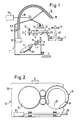
- an operating robot 1 can be moved along a ring bench 2 of a spinning machine. Upon a corresponding signal, it automatically positions itself at a specific spinning position, for example to correct a thread break or to Piecing.
- the robot is stored and guided via guide elements, for example guide rails 3 and 4, which are connected to the spinning machine.
- the robot contains, for example, a supply spool 5 for an auxiliary thread 6, a delivery mechanism 7 for pulling the auxiliary thread 6 from the supply spool 5, and a cutting device 9 for cutting a defined piece of auxiliary thread 6.1 from the auxiliary thread supply.
- Auxiliary devices 12 for example a thread winding device and / or a threading guide, may also be present in the robot 1, which are height-adjustable in the Z direction, for example, by means of a threaded spindle 13 and horizontally displaceable in the X direction, for example, by means of a linear drive 14.
- a thread store in the form of a suction pipe 15 is provided, which is connected by a hose 19 to a vacuum source 20.
- the suction pipe 15 is designed to receive a thread section of a certain length.
- the mouth 16 of the suction pipe 15 can be moved three-dimensionally under the influence of a program-controlled control 50, as is indicated by a servo axis 22 shown schematically in FIG. 1.
- the controller 50 can be designed, for example, as an autonomous robot controller in the form of a processor-equipped programmable control device which ensures automatic operation.
- the threading guide 12 is provided with a holder 26 for further components.
- a controllably rotatable ring 27 is mounted on the underside of the holder 26.
- the ring 27 is connected to a controllable drive 34.
- the ring 27 is provided with a passage 29.
- the bushing 29 is dimensioned such that the ring 27 can be pushed laterally over the thread tube 40 or over the thread body. However, the ring can also be closed and can be guided axially on or around the yarn tube 40.
- the entire holder 26 can be moved under the action of the drive 14 in the X direction e.g. move linearly towards the sleeve 40 between the ring bank 3 and the thread balloon ring 41 and slide with the ring opening 29 over the sleeve until the ring 27 is coaxial with the axis of rotation of the sleeve 40.
- Activation of the drive 34 causes the ring 27 to rotate a defined distance along the spinning ring 23.
- a small brush 31 is placed on the underside of the ring 27, which is used to move the rotor along the circumference of the ring 27, for example to temporarily keep the rotor out of a certain area of the ring, or also to hold the rotor during that described later Threading process to slide over the thread.
- one or more blowing nozzles 32 can be attached to the holder 26, which are provided with an air supply and can be activated in a controlled manner. They direct their blowing jet approximately tangentially to the spinning ring 23 in order to temporarily fix the rotor 24 on the opposite side of the spinning ring 23 when the compressed air is activated.
- two blowing nozzles 32A and 32B act on the spinning ring 23 in different directions of rotation.
- An air blast blows the runner outside the working area of the thread guide 25, while a time-controlled counter air blast positions the runner on the opposite side of the threading device.
- a slide 28 is attached to the holder 26 and can be displaced in the X direction under the influence of a drive 37, for example a pneumatic drive.
- the slide sits on the holder 26 off-center so that its main axis leads into the peripheral region of the sleeve 40 according to FIG. 3, preferably approximately tangentially to the spinning ring 23, so that its tip can be easily positioned over the upper sliding surface of the spinning ring 23.
- the slider 28 serves for the exact positioning of the thread during the threading into the runner described later by pushing the runner onto the thread.
- This is done by activating the delivery mechanism 7 with a specific positioning of the thread store 15, e.g. in position P.1 according to Fig. 5.
- the delivery mechanism 7 is switched off as soon as the desired length of auxiliary thread is in the tube of the thread store 15, e.g. when the auxiliary thread start 6.3 reaches a thread sensor 36 at the rear area of the thread store 15.
- the thread store 15, in the example its mouth 16 can be manipulated three-dimensionally.
- the mouth 16 of the thread store 15 makes a pendulum movement in the inner region of a winding ring 27, for example along the one in FIG 5 indicated path 39 in position P.2.
- the auxiliary thread is placed on a clamping device 35 on the underside of the winding ring 27.
- the mouth 16 of the thread store 15 is then moved back again, around the clamping device 35, into the starting position P.1, the auxiliary thread 6 being clamped in by the clamping device.
- the cutting device 9 separates the auxiliary thread 6 from the feed, so that a finite auxiliary thread piece 6.1 of a defined length is produced.
- this known auxiliary thread length is used, as a result of which various process steps can be better planned in advance and involve fewer uncertainties in the execution of the control programs.
- the auxiliary thread start 6.3 is still in the position of the sensor 36 within the thread store 15.
- the thread is held in the thread store 15 by the suction effect with a slight pull relative to the clamping pin 35.
- the controlled guidance of the auxiliary thread elastically retained in the thread store now takes place.
- the mouth 16 of the thread store 15 with the auxiliary thread piece is now servo-controlled in a lower unwinding position P.4, e.g. performed within the range of the ring bench movement, as shown schematically in Fig. 6.
- the ring 27 is caused to rotate a defined number of times, so that it winds the auxiliary thread end 6.2 held on the clamping device 35 around the sleeve 40 or around its package 43. During this winding process, the auxiliary thread is increasingly pulled out of the elastic retaining thread store 15.
- the sleeve 40 After taking over a certain length of auxiliary thread from the thread store 15, the sleeve 40 is braked to a standstill by means of a spindle brake, so that on the one hand a remaining auxiliary thread length is guaranteed in the thread store 15 and on the other hand the wound end of the auxiliary thread 6.2 cannot be pulled off the package, e.g. in a subsequent threading process.
- auxiliary thread start and end are held by components, the positions of which are clearly determined.
- the auxiliary thread which is thus elastically clamped between two "grippers", can be manipulated three-dimensionally in this way, so that the winding location on the sleeve 40, furthermore the type of winding formation and also the length of the auxiliary thread to be wound from the operating device, for example can be controlled by program specifications. Under these conditions, winding is ensured with a high degree of reliability.
- the winding process is controlled with the help of the thread storage device in a clearly defined sequence of movements, which is no longer influenced by coincidences, as was the case, for example, when blowing a free auxiliary thread end onto the package according to the prior art.
- the operating robot 1 can feed the auxiliary thread start 6.3 from the thread store 15 to the spinning station or the various thread guide elements, thread it into thread guide elements and finally attach it to the running fiber stream.
- a corresponding example for threading is shown below in connection with the schematic representation in FIG. 3.
- the sleeve 40 is taken by suitable measures, for example by actuating a spin that is not shown in detail in the figures del brake, braked to a standstill. Now the holder 26 is moved in the above-mentioned manner in the X direction towards the sleeve 40 by activation of the drive 14 and pushed with its opening 29 over the sleeve 40, so that the ring 27 is now coaxial with the sleeve 40.
- the ring 27 and with it the brush 31 are rotated around the sleeve 40 to such an extent that the brush 31 pushes the rotor 24 out of the working area of the slide 28. Thereafter, the holder 26 with the slide 28 located thereon is pushed back into the starting position outside the sleeve 40.
- the blowing nozzles 32 can also be activated for the same purpose instead of the rotary drive.
- the slide 28 is extended, for example by the slide drive 37, into the working position according to FIG. 3, just above the effective area of the now free spinning ring 23.
- the mouth of the suction pipe 15 assumes position A according to FIG. 3.
- the slider 28 engages in the thread piece 6.1.
- the notch 25 is designed and adapted to the surface of the spinning ring in such a way that it holds the thread in the respective position on the one hand and protects it on the other hand, so that the brush 31 does not damage, strip or take away the thread when it moves the rotor 24 can.
- the suction pipe 15 is guided with the thread piece 6.1 over the slide 28 and lowered with its mouth 16 into a position B which is lower than that of the slide 28.
- the tensioned thread piece 6.1 is located at a certain radial distance from the spinning ring 23. The in this way, part of the thread 6.1 clamped between the notch 25 and the mouth 16 of the suction pipe 15 is thus directed obliquely downwards.
- the thread 6 is pulled out of the elastically restraining suction pipe 15, if necessary, so that it remains taut throughout the entire course of movement.
- the suction pipe 15 is now moved into the position C, so that the thread 6.1 is tangent to the spinning ring 23 and still runs downwards from the notch 25 to the mouth 16 of the suction pipe 15.
- the tangential direction is inclined by an angle "alpha" with respect to the plane of the spinning ring 23, as indicated in FIG. 3.
- the value of "alpha" can be approximately 10 degrees.
- the holder 26 or the threading guide 12 is moved to the sleeve 40 by the drive 40, so that the ring 27 is again coaxial with the spinning ring 23 and the sleeve 40.
- the Z position is selected in a program-controlled manner such that the threading guide 12 is coupled to the holder 26 on the ring bench 3 according to FIG. 1, so that the holder 26 follows the lifting movements of the ring bench 3.
- the brush 31 on the spinning ring 23 is rotated clockwise in the example shown in FIG. 3, whereby it pushes the rotor 24 over the thread piece 6.1 lying obliquely downwards on the spinning ring 23 and thus the actual threading process of the thread in takes the runner.
- the slide 28 and its holder 26 are then retracted into their starting positions. The entire device is uncoupled from the moving ring bench 3.
- the operating robot 1 can then be used to thread the part of the thread piece 6.1 remaining in the suction pipe 15 into corresponding thread-guiding elements in a similar manner by corresponding program-controlled manipulations. Finally, the thread start 6.3 is attached to the current fiber stream. This last step is no longer part of the actual threading and is not described further here.
- the suction pipe 15 acts as a thread store in the context described. It brings about an elastic retention of the thread against the tensile force emanating from the braked sleeve 40.
- the thread storage device does not have to be designed as a suction tube, but it can also have any other design that is suitable for the elastically yielding retention of a thread piece.
- the thread to be threaded is held by components, the positions of which are clearly determined during each phase of the process sequence.
- the threading is thus controlled in a clearly defined movement sequence, which is no longer influenced by randomness and uncertainties, as was the case with known proposed solutions according to the prior art.
- the manipulable thread store achieves significantly improved reliability as a prerequisite for a fully automatic process sequence.
- the described method steps are triggered and coordinated by a central process control, in the example by a processor-equipped programmable control device, which is housed in the operating robot and ensures automatic operation.
- Certain sub-processes such as synchronization with processes on the spinning machine or the triggering of machine-specific spindle brakes, are coordinated and controlled via interfaces to the machine control.
- sequence control can also be implemented.
- the sequence of the method steps described is preferably contained in a program which, in conjunction with a process control, initiates the automatic execution of the method steps, for example using standardized computers.
- the manipulable thread store is particularly advantageous when the winding, threading and attachment process is carried out in combination.
- the thread storage device can in principle only be used for threading or for threading with subsequent attachment, without prior winding. In these cases, too, the advantages mentioned, which result from the precisely controllable thread manipulation, have a positive effect.
- the thread store 15 is part of the operating robot 1 and is designed to store an auxiliary thread piece from an auxiliary thread supply carried along, there are particular advantages for monitoring the auxiliary thread supply.
- the presence of the auxiliary thread can be arranged by arranging an auxiliary thread sensor 52 according to FIG. 1 Monitor gear of the delivery plant 7 within the operating robot 1. If the auxiliary thread is missing, the operating robot is put out of operation with regard to its subroutines "thread break repair or spinning" or “threading the auxiliary thread". This operating state is signaled to the outside by suitable optical signaling devices and / or signal paths to a computer or a signal processing device 50.
- the operating robot in the absence of the auxiliary thread, is moved to a predetermined position, e.g. at the end of the ring spinning machine, moved into a waiting position to wait for the auxiliary thread supply to be completed.
- a predetermined position e.g. at the end of the ring spinning machine
- the operator robot does not correct any further thread breaks during the journey to the waiting position.
- the operating robot is not automatically restarted until the auxiliary thread supply has been replaced.
- the auxiliary thread supply can be supplemented manually by operating personnel or automatically by a suitable auxiliary device.
- a further exemplary embodiment for determining the auxiliary thread consists in the arrangement of sensors of any type, for example optical or mechanical scanning sensors 54, which scan the diameter of the auxiliary thread package. If a given dimension for the diameter falls below, the above-mentioned state occurs, but in this If the auxiliary thread supply can be added before it is completely exhausted.
- the length of the auxiliary thread supply is measured and known.
- the thread quantity emitted by the auxiliary bobbin is continuously measured and recorded in a connected process computer in order to continuously calculate the remaining quantity therefrom and to initiate the refill measures described above when the value falls below a predetermined threshold.
- the thread storage device 15 is shown in the examples as a suction tube, it can also have a different design, which is suitable for the elastically yielding retention of a piece of thread and for program-controlled spatial manipulation.
- the freely manipulable thread store is also advantageous for other thread manipulations, for example when threading through direct detection of the spinning thread by the bobbin.
- the spinning thread can also be safely and securely threaded directly into thread guide elements of the spinning machine by manipulating the thread store.
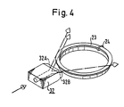
- FIGS. 7 to 20 In order to more clearly illustrate the threading process described above, a detailed description is given below with reference to FIGS. 7 to 20. For the sake of simplicity, other reference symbols are used here, although many parts or method steps described below have already been explained in connection with FIGS. 1 to 6. The numbering used in FIGS. 7 to 20 also allows a clear assignment to the corresponding priority application.
- reference numeral 100 indicates the chassis of the operating robot for operating spinning positions on a ring spinning machine.
- Each such spinning station contains an assembly 101 for imparting twist and for unwinding the yarn; this unit 101 here comprises a spindle 102, a spinning ring 106 carried by a ring bench 104 and a rotor (not shown) mounted on the spinning ring 106.
- the chassis 100 runs along a machine side on bicycles 105 guided by a guide rail 103.
- a support arm 107 carries a guide roller 109 which runs in a further guide rail 113 carried by the machine and holds the chassis 100 in a predetermined position with respect to the machine.
- the guide rail 113 is mounted on the machine frame (not shown) by a suitable holder 115.
- the operating robot comprises both an attaching device 150, which should be explained in more detail below, and a handling device 124, which is described in detail in the aforementioned sister application and therefore only in this application has been treated sketchily.
- the handling device 124 namely comprises a suction tube 134 for receiving a predetermined thread length (not shown) with a mouth part 136 and a connection 138 to a vacuum source 132 carried by the chassis 100.
- the mouth part 136 of the suction tube 134 can be indicated by a controllable articulation system 140 (only schematically indicated) ) can be moved relative to the chassis 100.
- the mouth part 136 is brought to a delivery point 128 for receiving thread 144 from a thread supply 122 carried by the chassis 100.
- the thread is delivered from a delivery mechanism 126 mounted on the chassis 100 via the delivery point 128 into the suction pipe 134 until this pipe has taken up a predetermined thread length.
- the articulation system 140 of the handling device is then actuated in order to establish a “connection” with the winding device 150. This "connection" will be described in more detail below and has also been dealt with in the aforementioned Swiss patent application No. 4852/88.
- the thread 144 is separated between the delivery mechanism 126 and the winding device 150 (separating means not shown), so that the thread length picked up can now be manipulated by the handling device 124 and winding device 150 independently of the supply 122 in accordance with a predetermined control program .
- FIG. 7 The schematic representation in FIG. 7 is favorable for identifying the different parts in that these parts have been shown far apart.
- the illustration is unrealistic in that the mouth part 136 and the winding device 150 are sealed must be guided side by side after they have entered a single spinning station via the "surface line" 117 of the machine.
- both the handling device 124 and the winding device 150 can be retracted into the chassis 100, so that the robot has a clear distance L from the surface line 117 when driving along the machine (with the exception of the guide system 107, 109).
- the winding device 150 must be movable in a direction (the “X direction”) transverse to the vertical longitudinal axis of the spindle 102.
- the device must be movable in one direction (the "Z direction”) along the spindle axis, as is clear from the description below.
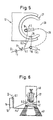
- FIG. 8 schematically shows a drive system for moving the winding device 150 both in the X and in the Z direction.
- the device 150 is mounted on the piston rod 200 of a piston-cylinder unit 202.
- a suitable source not shown
- the piston is pressed from its retracted position to the right according to the side view in FIG. 8 against the spindle 102.
- This movement is limited by a suitable stop (not shown) in order to hold the winding device 150 in a suitable, still to be described working position relative to the spindle 102.
- the device 150 will return from its working position to a retracted position.
- the unit 202 is mounted on a slide 186, which in turn is mounted on a threaded spindle 196 via a carrier 184.
- Spindle 196 is in Chassis 100 is mounted vertically (ie essentially parallel to the longitudinal axis of spindle 102) and coupled at one end to a drive motor 204.
- the drive motor 204 is controlled by a microprocessor with suitable programming (software); However, in order to depict the control method visually, the control program is indicated schematically by control loops or a control box. In a first state, the motor 204 is controlled by a sensor 206 via a first controller 208, in a second state by the same sensor 206 via a second controller 210 and in a third state by a controller 212.
- the sensor 206 responds to the position of the ring bench 104 in order to position the slide 186 with the winding device 150 accordingly in the Z direction.
- the signal emitted by the sensor 206 is delivered to the first controller 208 via the switching means 214 while the robot is traveling and is delivered by switching from the switching means 214 to the second controller 210 during a certain phase of the operating work (as will be explained in more detail below).
- the controller 212 controls the drive motor 204 when the position of the carriage 186 needs to be controlled independently of the ring bench position, e.g. when picking up the auxiliary thread at delivery point 128 (FIG. 7).
- the individual spinning positions of a ring spinning machine are shielded from one another in the longitudinal direction of the machine by so-called separators 194.
- the working head shown in FIG. 9 comprises a carrier section 220 which remains outside the spinning station space defined by the separators 194 and a C-shaped part 222 which projects into the space of the spinning station to be operated in all working positions of the winding device 150.
- the C-shaped part 222 surrounds (in part) a C-shaped operating runner 224 and forms a guide in the form of a track 226 for the operating runner.
- These two C-shaped parts 222, 224 have a common axis P, which in all working positions of the winding device is aligned with the longitudinal axis of the spindle 102 or in the vicinity of the spindle axis and approximately parallel to it.
- the operator runner 224 is rotatable in the track 226 about the axis P relative to the C-shaped part 222.
- the operating rotor 224 is provided with a ring gear 228 (indicated by dashed lines) and this ring gear meshes with two toothed rollers 230.
- the rollers 230 in turn mesh with the ring gear a drive pulley 232 which is rotatably mounted in the carrier section 220 and by a suitable one Drive motor 234 can be rotated.
- the opening 236 of the operating rotor 224 with the opening must be 238 of the C-shaped Part 222 be aligned.
- the operator runner 224 is therefore provided with a suitable marking (not shown) and the C-shaped part 222 carries a sensor 240 which reacts to this marking in order for this "ready position" of the operator runner 224 relative to its holder 222 to the controller (not shown) ) for the engine 234.
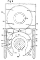
- the access opening 240 formed thereby is wide enough to receive the spindle 102 and a sleeve 112 carried by it (FIG. 10, not indicated in FIG. 9), but not a cop 116 formed on the sleeve 112 (FIG. 10).
- the feed device 150 must therefore be fed to the spindle 102 at a height (along the spindle axis) which lies above the currently highest winding position of the spinning ring 16 (FIG. 10).
- the distance between the transfer rollers 230 in the circumferential direction of the operating rotor 224 is selected such that if one roller 230 no longer meshes with the ring gear 228 due to the discontinuity caused by the access opening 240, the transmission of the drive forces from the disk 232 to the others remains Guaranteed roles on the operator runner 224.
- the operating rotor 224 carries two working elements 242, 244.
- the element 242 comprises a pin which runs vertically through a suitable bore in the operating rotor 224 and is provided with a clamping head 246 on the underside of the rotor 224.
- the pin is pushed up by a suitable spring load (not shown) to hold the clamping head 246 in a clamping position contacting the underside of the operator rotor.
- actuating mechanism 248 mounted on the carrier section 220.
- This mechanism includes a rocker arm 250 with a head 252 which is just above the pin when the operator runner 224 is in its ready position ( Figures 9 and 10).
- the head 242 By tilting the lever 250 (e.g. by means of a pneumatic device on the carrier part 220, not shown) in a clockwise direction according to FIG. 10, the head 242 can initially be brought into contact with the pin and then moved on to the pin with the clamping head 246 against the spring load to push down.
- the device 150 is brought near the delivery point 128 by the actuation of the motor 204 (FIG. 8) by the controller 212, the operator runner 224 being held in its ready position in relation to the part 222.
- the actuation of the motor 204 FIG. 8
- the operator runner 224 By suitable movements of the mouth part 136 (see in this connection the Swiss patent application No. 4852/88) and the opening of the clamping device by the actuating mechanism 248, an auxiliary thread extending between the mouth part 136 and the delivery point 128 is moved into the clamping device and by releasing the Mechanism 248 is connected to the operator runner 224 by clamping.
- the winding device 150 and the handling device 124 together form an attachment unit, which can first connect the stored auxiliary thread to the winding unit 101, then thread it with the thread guide elements of the spinning station and finally with one of a drafting system (not shown). supplied roving.
- the second working element 244 is a flexible element e.g. a brush to strip the upward surface of the ring 106. This element is used to move the rotor on the spinning ring 106 as should be described in more detail below.
- the carriage 186 is moved upward by actuating the motor 204 in order to move the device 150 into a predetermined position with respect to the currently uppermost turns W (FIG 10) to bring the cop.
- the highest position of the ring bench 104 is sensed and stored while the robot is moving, so that the controller 208 is able to bring the slide 186 immediately to the appropriate working height (along the threaded spindle 196) after leaving the delivery point 128 .
- the unit 202 is actuated to move the device 150 against the spindle 102 into the first working position (FIG. 10).
- the clamping plane formed by the clamping head 246 and the operating rotor 224 lies above the uppermost windings W of the cop at a predetermined distance (not shown).
- a thread break can already occur in the first phase of the bobbin formation, so that the first working position would then lie much further down relative to the spindle 102 and sleeve 112. If the thread breaks during a doffing process, it can even happen that the the corresponding spinning station is not started at all, so that the auxiliary thread must be connected to the "bare" sleeve.
- the correct first job can still be determined in relation to the uppermost position of the ring bench 104 during its traversing movement.
- the operating runner 224 is held in its standby position during this infeed movement, so that the access opening 240 for receiving the spindle 102 and sleeve 112 is present.
- the mouth part 136 is brought to a corresponding work station, so that the mouth M (FIG. 1 lies below the clamping plane at a distance to be described.
- the auxiliary thread F extends between the mouth M and the clamping head 246 with a vertical distance between the Mouth M and inclination corresponding to the clamping plane (solid line in FIG. 10).
- the motor 234 (FIG. 9) is now actuated in order to rotate the operator runner 224 in its career 226 (FIG. 9) clockwise according to FIG. 6 about the axis P.
- This rotation initially shortens the distance between the mouth M and the clamping head 246, the "unnecessary" length of the thread F being absorbed by the suction in the tube 134.
- the thread F is pulled out of the suction tube 134 again by further rotations of the operating rotor 224 with the clamping head 246 and placed on the sleeve 112 or the outer turns of the cop 116 (FIG. 12).
- the first turn of the thread F runs down a spiral around the sleeve 112 and cop 116 until the thread F lies in a horizontal plane containing the mouth M (dashed line in FIG. 10).
- some connecting turns V (FIG. 10) are formed in this plane.
- the aforementioned distance between the mouth M and the clamping plane is selected such that, if a cop 116 is present at all, these first connecting windings V lie below the uppermost winding W of the cop.
- the work site of the mouth M is therefore below the uppermost position of the ring bench 104 during its traversing movement, so that this work site must be kept outside the movement area of the ring bench 104 (see FIG. 11).
- the first turns V are formed by rotating the operating rotor 224 both with respect to the spindle 102 or sleeve 112 and with respect to the C-shaped holder 222.
- the thread F is pulled directly from the suction pipe 134 by the rotation of the operating rotor 224.
- the rope effect between the thread F and the cop 116 becomes so great that a weaker thread F would break between the clamping head 246 and the turns V when the spindle 102 was stationary.
- the spindle 102 is released from its drive (not shown) during the winding process, so that it can currently be freely rotated (see in this connection the Swiss patent application No. 4852/88) .
- the mouth part 136 is also moved upwards in order to wind further binding turns B (FIG. 13) on the sleeve 112, these turns B securely binding the above-mentioned piece of thread to the sleeve 112.
- the turns B also serve another purpose, but this only becomes clear when a later phase of the process is explained and is therefore only discussed later in this description.
- the spindle 102 In order to form these last bindings B, the spindle 102 must still be able to rotate freely and the thread F must remain intact between the bindings formed on the sleeve and the clamping head 246. However, after this second winding phase has been completed, the spindle 102 is braked by suitable means (not shown) while the operator runner 224 continues to run. The thread F is thereby pulled out of the clamping head 246 and forms a free end FA (FIG. 14).
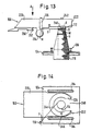
- the mouth part 136 is brought from its second working position (FIG. 13 and FIG. 15, solid lines) to a third working position on the other side of the spindle 102 and winding device (dashed lines in FIG. 15) .
- a slide 260 carried by the carriage 186 is now moved from a retracted position (FIGS. 10 and 13) to an advanced position (FIGS. 14 and 17 to 20) by a suitable actuating means (for example by a pneumatic piston and cylinder unit, not shown) .
- a V-shaped guide part 262 (FIGS. 10, 13 and 19) engages in the free thread length between the sleeve 112 and the mouth part 136.
- Slider 260 is advanced so far that the thread length mentioned is deflected by the guide part 262 and finally held in a predetermined position becomes. This position is determined by a suitable end stop (not shown) for the slide 260.
- the mouth part 136 is now moved upwards and then brought back onto the first side of the spindle 102 and angling device 150 (FIG. 17).
- the mouth M is moved downwards so that the thread F runs underneath the winding device 150 and between the mouth M and the edge of a guide surface FF (FIG. 15) on the uppermost surface of the slide 260 a predetermined inclination upwards (in FIG 12 not visible).
- the slider 260 is provided with a constriction 261 (FIG. 15) in order to guide the thread on the surface FF.
- the position of the mouth part 136 is now selected so far away from the ring bench 104 that the thread F lies outside the movement space of the ring 106 (FIG. 17).
- the winding device 150 is now shifted back into its second working position (FIG. 18), after which the threading preparation phase is completed.
- FIG. 16 schematically shows the cop 116, the yarn G during normal spinning and the runner 108, the direction of rotation of the cop being indicated by the arrow R. This direction of rotation is also indicated by an arrow on the spindle 102 in FIG. 15, although the spindle may not actually rotate during the preparation phase.
- certain geometrical relationships must prevail when threading the auxiliary thread F with the rotor 108.
- the thread length to be threaded must extend from the left to the right from the slide 260 to the mouth part 136.
- this thread length must have a slight inclination from above on the slide 260 downward at the mouth 136.
- This inclination ⁇ is indicated in FIG. 18 (in this figure part of the cop 116 has been "cut away” to show the guide head of the slider 260).
- the runner 108 has to be pushed onto the thread F by moving along the spin ring 106 in a clockwise direction according to FIG.
- the auxiliary thread length extending between the runner 108 and the mouth part 136 can then be pulled upwards in order to correspond to the position of the thread length G (FIG. 16).
- the conditions previously described depend on the direction of rotation of the spindle 102, which in turn depends on the yarn rotation (S or Z rotation).
- the conditions described are adapted for a yarn with an S twist, which corresponds to the products of most spinning mills.
- the slide 260 When producing yarn with a Z twist, the slide 260 would have to be laid on the other side of the spindle 102 (again in the direction of the arrow L, viewed in FIGS. 10, 12 and 13) and the thread length to be threaded would have to be from the right to the left of the slide 260 extend to the mouth part 136.
- the device 150 In order to produce the conditions already described, the device 150 must in any case be moved into its retracted position, at least in order to enable the orifice part 136 to be moved after the thread F has been brought into contact with the guide part 262 of the slide 260. For the winding it does not matter whether the mouth part 136 is placed to the left or to the right (viewed in the direction of the arrow L) relative to the winding device 150.
- the position of the clamping point 242 in the circumferential direction of the operating rotor 224 also does not play a major role in this regard.
- the clamping point 242 can preferably be brought as close as possible to the separating means (not shown) for separating the thread between the clamping point and the delivery mechanism 126 (FIG. 7) in order to avoid a long thread end which depends on the clamping point.
- the switching means 214 is switched to the controller 210 (FIG. 9) and the motor 204 is activated in order to move the slide 186 down the threaded spindle 196 until the sensor 206 has the ring bench 104 "finds".
- the mouth part 136 is moved accordingly, so that the already prepared conditions are maintained.
- the sensor 206 scans contactlessly for the ring bank 104.
- the sensor 206 After the sensor 206 has "found" the ring bench 104, the sensor sends a signal to the controller 210 to keep the motor in continuous operation, so that the carriage 186 together with the winding device 150 follows the movements of the ring bench 104.
- the clamping plane of the operating rotor 224 is obtained at a predetermined distance S (FIG. 19) above the upward surface of the ring bench 104.
- the second working element (the brush) 244 is held in contact with the upwardly facing surface of the ring 106.
- the vertical movements of the ring bench 104 are followed without contact as previously indicated and therefore without loading the ring bench drive (not shown).
- the positioning of the winding device 150 in the X direction (FIG. 7) to ensure that the brush 244 is in contact with the spinning ring 106 is, however, effected by a feeler roller 264 mounted on the device 150. This touch does not burden the ring bench drive.
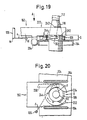
- FIG. 20 shows the last movement of the threading process, the operating runner 224 being rotated again clockwise around the axis P, thereby also moving the runner 108 (not visible in FIG. 20) clockwise along the spinning ring 106 along the thread length between the mouth part 136 and to move the slider 260.
- the mouth part 136 is to be brought in the direction of the ring bank 104 into the position shown in FIG. 20 and the thread piece to be threaded is placed close to the spinning ring 106, the inclination ⁇ (FIG. 20) being maintained.
- the runner 108 is at a suitable location opposite the spinning ring 106 so that the brush 244 can push it in the desired direction.
- This is actually preferably the first step in the whole process and is even carried out before the auxiliary thread length is fetched.
- the winding device is continuously held along its "working height" along the threaded spindle 196 by the control system shown in FIG.
- the sensor 206 senses the upper reversal point of the ring bench movement while the robot is traveling and uses it to adjust the position of the slide 186.
- the device When a thread break is detected or after positioning at the spinning position to be operated, the device can be immediately delivered to the spindle 102 in question (in the first working position, FIG. 10) and the carriage 186 can then be moved down to the device Dock ring ring 104 (in the third working position, Figure 19 - as already described for threading). The operator runner can then be actuated to place the runner in a predetermined position (eg, position X in Figure 20) where it will neither interfere with nor prepare for threading.
- a predetermined position eg, position X in Figure 20
- the motor 204 can then be started again in order to uncouple the device from the ring bench and return it to the first working position (FIG. 10), so that it can be pulled back into the robot for picking up the auxiliary thread from the delivery point 28.
- the motor 204 is controlled independently of the position of the ring bench 104 in order to e.g. to the lower end of the spindle 196 and thereby in the vicinity of the delivery point 28.
- the "working height" (the height of the first working position along the spindle 102) is saved, so that after the auxiliary thread has been picked up, the attachment unit (winding device 150 and handling device 124) can be brought back to the working height immediately. The procedure already described can then be carried out.
- the movement of the operating rotor 224, indicated in FIG. 20, encompasses one full revolution of this organ, so that the brush 244 runs over the thread length extending between the sleeve 112 and the slide 260.
- Contact between the bust 244 and the thread length F should, however, be avoided if possible, since otherwise the thread run could be destroyed.
- the guide part 262 of the slide 260 is therefore provided with a screen piece 266 (best seen in FIGS. 15 and 17), which in the threading position (FIG. 18) lies directly above a section of the spinning ring 106 and the thread F from the brush 244 during the shields the aforementioned threading revolution of the operating rotor 224.
- the first sister registration shows that the handling device 124 is also carried by the slide 186.
- the thread F (after the slide 108 has been pushed on) can be moved upwards by the handling device 124.
- the auxiliary thread F remains threaded with the rotor 108 and is pulled out of the suction pipe 134.
- a thread length also remains between the runner 108 and the cop 116.
- the tensile force that is exerted on the auxiliary thread F acts in the opposite direction to the tensile force that is exerted during normal spinning (starting from the cop 116). If the auxiliary thread F now runs in a substantially horizontal position from the runner 108 to the cop 116, the forces exerted by the auxiliary thread F on the runner 108 could under certain circumstances be sufficient to move the runner along the spinning ring 106, in that for the Spinning normal direction (clockwise in Figure 15). However, since the spindle 102 was still stationary at this time, this movement of the runner would mean the pulling of thread windings from the bobbin, which could lead to a further thread break when attaching for various reasons.
- the upper turns during winding ie the binding turns B, FIG. 13
- the thread length extending from the windings B to the rotor 108 always has an upward slope as seen away from the rotor 108.
- the of the thread lengths on both sides of the runner on these forces exerted during the further threading phases only partially compensate for one another and give a resultant that raises the runner 108 upwards against the underside of the spinning ring 106 rather than moving the runner along the spinning ring. An unfavorable development of wound binding turns B is avoided.
- connection of the auxiliary thread piece with the yarn carrier finally takes place due to the rotational movement of the one holder in the form of the winding ring with a clamping device around the yarn carrier.
- a connection between the auxiliary thread piece and the thread carrier is achieved at a desired point in time by the action of friction. It is obvious that this principle can also be implemented in other ways.
- the essence of the invention therefore lies in a method for applying an auxiliary thread to a yarn carrier of a spinning machine located at the spinning position, the method being characterized in that an auxiliary thread piece clamped on two sides in holders is placed on the thread carrier and with one of the holders around the thread carrier is looped until the auxiliary thread piece is connected to the yarn carrier by friction.
- this principle can best be achieved when the yarn carrier stands still during the wrap movement, and is preferably also freely rotatable.
- the yarn carrier is first uncoupled from the normal drive of the spinning station and then driven by a separate rotary drive, for example by a drive that is located on the operating device and the sleeve or the spindle, for example, with drives a rubber wheel to rotate by friction.
- the winding ring initially produces a few loose turns around the thread carrier and that the sleeve and therefore the thread carrier is then driven to a separate rotary movement in order to tighten these loose windings and therefore the required friction connection between the auxiliary thread piece and to establish the thread carrier.
- This could be done, for example, in that at the beginning of the wrap the separate drive for the yarn carrier drives the yarn carrier at the same rotational speed as that of the winding ring and then changes the rotational speed of the thread carrier with respect to the winding ring, preferably accelerates, in order to tighten the wraps that have taken place and at the right moment pull the end of the auxiliary thread piece out of the clamping device or release it by releasing the clamping device.
- the separate drive could then be detached from the thread carrier and the process continued, as previously described in detail, until the spinning station produced again.
Applications Claiming Priority (8)
| Application Number | Priority Date | Filing Date | Title |
|---|---|---|---|
| CH1057/89 | 1989-03-22 | ||
| CH105589 | 1989-03-22 | ||
| CH1055/89 | 1989-03-22 | ||
| CH105789 | 1989-03-22 | ||
| CH112289 | 1989-03-28 | ||
| CH1122/89 | 1989-03-28 | ||
| CH1121/89 | 1989-03-28 | ||
| CH112189 | 1989-03-28 |
Publications (3)
| Publication Number | Publication Date |
|---|---|
| EP0391110A2 true EP0391110A2 (fr) | 1990-10-10 |
| EP0391110A3 EP0391110A3 (fr) | 1991-01-02 |
| EP0391110B1 EP0391110B1 (fr) | 1995-10-18 |
Family
ID=27428070
Family Applications (1)
| Application Number | Title | Priority Date | Filing Date |
|---|---|---|---|
| EP19900105020 Expired - Lifetime EP0391110B1 (fr) | 1989-03-22 | 1990-03-16 | Procédé et dispositif pour enfiler un fil partiellement enroulé sur une bobine de fil dans un métier à filer |
Country Status (3)
| Country | Link |
|---|---|
| EP (1) | EP0391110B1 (fr) |
| JP (1) | JPH0351331A (fr) |
| DE (1) | DE59009778D1 (fr) |
Cited By (10)
| Publication number | Priority date | Publication date | Assignee | Title |
|---|---|---|---|---|
| WO1992021803A1 (fr) * | 1991-05-31 | 1992-12-10 | Maschinenfabrik Rieter Ag | Station d'entretien pour un robot auxiliaire |
| WO1992021804A1 (fr) * | 1991-05-31 | 1992-12-10 | Maschinenfabrik Rieter Ag. | Procede pour la surveillance et pour l'echange ou le remplacement de curseurs sur les anneaux a filer de points de filage dans un metier a filer a anneaux |
| EP0960964A1 (fr) * | 1998-05-27 | 1999-12-01 | OFFICINE GAUDINO SpA | Procédé et appareil pour le raccordement automatique d'un fil au stade de formation dans un métier à filer |
| DE10338326A1 (de) * | 2003-08-21 | 2005-03-24 | Rieter Ingolstadt Spinnereimaschinenbau Ag | Verfahren und Wartungseinrichtung zum Betreiben von Spinnmaschinen mit wenigstens einer Hilfsspule |
| CN110067054A (zh) * | 2018-01-24 | 2019-07-30 | 里特机械公司 | 将纱线端部穿纱到钢领钢丝圈内的方法和装置 |
| CZ307898B6 (cs) * | 2018-01-31 | 2019-07-31 | Rieter Cz S.R.O. | Zařízení pro manipulaci s koncem příze na spřádacím místě prstencového spřádacího stroje, způsob manipulace s koncem příze a prstencový spřádací stroj |
| EP3626871A1 (fr) * | 2018-09-21 | 2020-03-25 | Saurer Spinning Solutions GmbH & Co. KG | Chariot de service et procédé d'alimentation automatique des postes de filage d'un métier à filer |
| WO2020058775A1 (fr) | 2018-09-19 | 2020-03-26 | Maschinenfabrik Rieter Ag | Procédé de fonctionnement d'un robot d'entretien d'un métier à filer à anneaux |
| EP3708701A1 (fr) * | 2019-03-15 | 2020-09-16 | Premier Evolvics PVT. Ltd. | Dispositif, système et procédé de résurrection de cassure de fil dans une machine à filer à anneaux |
| EP4063543A1 (fr) * | 2021-03-23 | 2022-09-28 | Pinter Caipo, S.A.U. | Système et procédé de rattachement de fil pour rattacher des fils auxiliaires au niveau d'une station de filage d'une machine à filer à anneau et outil de manipulation de fil à utiliser avec ledit système |
Citations (6)
| Publication number | Priority date | Publication date | Assignee | Title |
|---|---|---|---|---|
| GB1189528A (en) * | 1966-03-14 | 1970-04-29 | Leesona Corp | Apparatus for Automatically Joining Yarn Ends |
| DE2361969A1 (de) * | 1973-12-13 | 1975-06-26 | Zinser Textilmaschinen Gmbh | Fahrbare einrichtung zur selbsttaetigen behebung von fadenbruechen an textilmaschinen |
| DE2501338A1 (de) * | 1974-01-23 | 1975-07-24 | Saco Lowell Corp | Wartungsvorrichtung fuer spinnoder zwirnmaschinen |
| DE2612660A1 (de) * | 1975-10-03 | 1977-04-07 | Cognetex Spa | Automatische ringlaeufervorrichtung zum auffinden und anlegen von gebrochenen faeden in spinnmaschinen fuer textilfasern von woll- oder baumwollaenge |
| JPS63182424A (ja) * | 1986-09-22 | 1988-07-27 | Teijin Ltd | 自動走行作業装置 |
| EP0303201A1 (fr) * | 1987-08-11 | 1989-02-15 | Zinser Textilmaschinen GmbH | Procédé et dispositif de rattachement automatique d'un continu à filer à anneaux |
-
1990
- 1990-03-16 DE DE59009778T patent/DE59009778D1/de not_active Expired - Fee Related
- 1990-03-16 EP EP19900105020 patent/EP0391110B1/fr not_active Expired - Lifetime
- 1990-03-20 JP JP6856690A patent/JPH0351331A/ja active Pending
Patent Citations (6)
| Publication number | Priority date | Publication date | Assignee | Title |
|---|---|---|---|---|
| GB1189528A (en) * | 1966-03-14 | 1970-04-29 | Leesona Corp | Apparatus for Automatically Joining Yarn Ends |
| DE2361969A1 (de) * | 1973-12-13 | 1975-06-26 | Zinser Textilmaschinen Gmbh | Fahrbare einrichtung zur selbsttaetigen behebung von fadenbruechen an textilmaschinen |
| DE2501338A1 (de) * | 1974-01-23 | 1975-07-24 | Saco Lowell Corp | Wartungsvorrichtung fuer spinnoder zwirnmaschinen |
| DE2612660A1 (de) * | 1975-10-03 | 1977-04-07 | Cognetex Spa | Automatische ringlaeufervorrichtung zum auffinden und anlegen von gebrochenen faeden in spinnmaschinen fuer textilfasern von woll- oder baumwollaenge |
| JPS63182424A (ja) * | 1986-09-22 | 1988-07-27 | Teijin Ltd | 自動走行作業装置 |
| EP0303201A1 (fr) * | 1987-08-11 | 1989-02-15 | Zinser Textilmaschinen GmbH | Procédé et dispositif de rattachement automatique d'un continu à filer à anneaux |
Non-Patent Citations (1)
| Title |
|---|
| PATENT ABSTRACTS OF JAPAN, Band 12, Nr. 462 (C-549)[3309], 5. Dezember 1988; & JP,A,63 182 424 (TEIJIN LTD); Das ganze Dokument. * |
Cited By (13)
| Publication number | Priority date | Publication date | Assignee | Title |
|---|---|---|---|---|
| WO1992021803A1 (fr) * | 1991-05-31 | 1992-12-10 | Maschinenfabrik Rieter Ag | Station d'entretien pour un robot auxiliaire |
| WO1992021804A1 (fr) * | 1991-05-31 | 1992-12-10 | Maschinenfabrik Rieter Ag. | Procede pour la surveillance et pour l'echange ou le remplacement de curseurs sur les anneaux a filer de points de filage dans un metier a filer a anneaux |
| EP0960964A1 (fr) * | 1998-05-27 | 1999-12-01 | OFFICINE GAUDINO SpA | Procédé et appareil pour le raccordement automatique d'un fil au stade de formation dans un métier à filer |
| DE10338326A1 (de) * | 2003-08-21 | 2005-03-24 | Rieter Ingolstadt Spinnereimaschinenbau Ag | Verfahren und Wartungseinrichtung zum Betreiben von Spinnmaschinen mit wenigstens einer Hilfsspule |
| EP3521487A1 (fr) * | 2018-01-24 | 2019-08-07 | Maschinenfabrik Rieter AG | Procédé et dispositif d'enfilage d'une extrémité de fil dans un curseur |
| CN110067054A (zh) * | 2018-01-24 | 2019-07-30 | 里特机械公司 | 将纱线端部穿纱到钢领钢丝圈内的方法和装置 |
| CN110067054B (zh) * | 2018-01-24 | 2023-04-28 | 里特机械公司 | 将纱线端部穿纱到钢领钢丝圈内的方法和装置 |
| CZ307898B6 (cs) * | 2018-01-31 | 2019-07-31 | Rieter Cz S.R.O. | Zařízení pro manipulaci s koncem příze na spřádacím místě prstencového spřádacího stroje, způsob manipulace s koncem příze a prstencový spřádací stroj |
| WO2020058775A1 (fr) | 2018-09-19 | 2020-03-26 | Maschinenfabrik Rieter Ag | Procédé de fonctionnement d'un robot d'entretien d'un métier à filer à anneaux |
| EP3626871A1 (fr) * | 2018-09-21 | 2020-03-25 | Saurer Spinning Solutions GmbH & Co. KG | Chariot de service et procédé d'alimentation automatique des postes de filage d'un métier à filer |
| CN110938901A (zh) * | 2018-09-21 | 2020-03-31 | 卓郎纺织解决方案两合股份有限公司 | 用于纺纱机的纺纱位的自动供应的维护车和方法 |
| EP3708701A1 (fr) * | 2019-03-15 | 2020-09-16 | Premier Evolvics PVT. Ltd. | Dispositif, système et procédé de résurrection de cassure de fil dans une machine à filer à anneaux |
| EP4063543A1 (fr) * | 2021-03-23 | 2022-09-28 | Pinter Caipo, S.A.U. | Système et procédé de rattachement de fil pour rattacher des fils auxiliaires au niveau d'une station de filage d'une machine à filer à anneau et outil de manipulation de fil à utiliser avec ledit système |
Also Published As
| Publication number | Publication date |
|---|---|
| EP0391110B1 (fr) | 1995-10-18 |
| EP0391110A3 (fr) | 1991-01-02 |
| DE59009778D1 (de) | 1995-11-23 |
| JPH0351331A (ja) | 1991-03-05 |
Similar Documents
| Publication | Publication Date | Title |
|---|---|---|
| EP1749906B1 (fr) | Arrangement de rattachement pour une métier à filer à bout libre à rotor | |
| DE102007056561A1 (de) | Kreuzspulen herstellende Textilmaschine | |
| DE10139075A1 (de) | Offenend-Rotorspinnmaschine | |
| EP3498896B1 (fr) | Procédé de fonctionnement d'un module de service | |
| DE3637172A1 (de) | Verfahren und vorrichtung zum erhoehen der spulgeschwindigkeit eines spulautomaten | |
| WO2008043408A1 (fr) | Poste de travail d'une machine pour textile | |
| DE3446159A1 (de) | Vorrichtung zur automatischen entnahme der garnwickel von spinnmaschinen | |
| DE4443818B4 (de) | Kreuzspulen herstellende Textilmaschine | |
| CH689921A5 (de) | Kreuzspulen herstellende Textilmaschine mit einer Serviceeinrichtung. | |
| DE3602574A1 (de) | Kreuzspulen herstellende maschine mit fahrbarem bedienungsaggregat | |
| DD299664A5 (de) | Betriebsverfahren und vorrichtung zum automatisierten auswechseln von auflaufspulen, insbesondere zwirnkreuzspulen, gegen leere aufwickelhuelsen | |
| EP0391110A2 (fr) | Procédé et dispositif pour enfiler un fil partiellement enroulé sur une bobine de fil dans un métier à filer | |
| EP0852216B1 (fr) | Machine textile pour la production de bobines à spires croisées | |
| EP2813605A1 (fr) | Procédé de fonctionnement d'un poste de travail d'un métier à filer à rotor à bout libre et poste de travail associé | |
| EP0410021B1 (fr) | Procédé et dispositif pour remplacer automatiquement les adaptateurs pour bobines garnis de bobines vides avec les adaptateurs pour bobines garnis de bobines pleines dans le poste de traitement de fil d'une machine textile | |
| DE2230801A1 (de) | Automatische spulmaschine | |
| DE3828323A1 (de) | Verfahren und vorrichtung zum aufnehmen eines fadenendes einer spule beim anspinnen | |
| DE3932727C2 (fr) | ||
| DE19523938A1 (de) | Topfspinnmaschine | |
| DE3344993A1 (de) | Mehrstellige textilmaschine | |
| DE3909746A1 (de) | Verfahren zum betrieb einer ringspinnmaschine sowie bedienroboter zur durchfuehrung des verfahrens | |
| WO2019096625A1 (fr) | Dispositif de filage à l'état fondu | |
| CH663200A5 (de) | Verfahren zum erzeugen oder bearbeiten und aufwickeln von faeden. | |
| EP0382943B1 (fr) | Procédé et dispositif pour déposer un fil auxiliaire sur une bobine dans un métier à filer | |
| DE1510865B1 (de) | Vorrichtung fuer Doppeldrahtzwirnmaschinen zum selbsttaetigen Wechseln von Spuleneinheiten |
Legal Events
| Date | Code | Title | Description |
|---|---|---|---|
| PUAI | Public reference made under article 153(3) epc to a published international application that has entered the european phase |
Free format text: ORIGINAL CODE: 0009012 |
|
| AK | Designated contracting states |
Kind code of ref document: A2 Designated state(s): CH DE ES FR GB IT LI |
|
| PUAL | Search report despatched |
Free format text: ORIGINAL CODE: 0009013 |
|
| AK | Designated contracting states |
Kind code of ref document: A3 Designated state(s): CH DE ES FR GB IT LI |
|
| 17P | Request for examination filed |
Effective date: 19910102 |
|
| 17Q | First examination report despatched |
Effective date: 19920915 |
|
| GRAA | (expected) grant |
Free format text: ORIGINAL CODE: 0009210 |
|
| AK | Designated contracting states |
Kind code of ref document: B1 Designated state(s): CH DE ES FR GB IT LI |
|
| PG25 | Lapsed in a contracting state [announced via postgrant information from national office to epo] |
Ref country code: GB Effective date: 19951018 Ref country code: FR Effective date: 19951018 Ref country code: ES Free format text: THE PATENT HAS BEEN ANNULLED BY A DECISION OF A NATIONAL AUTHORITY Effective date: 19951018 |
|
| REF | Corresponds to: |
Ref document number: 59009778 Country of ref document: DE Date of ref document: 19951123 |
|
| ITF | It: translation for a ep patent filed |
Owner name: GUZZI E RAVIZZA S.R.L. |
|
| PGFP | Annual fee paid to national office [announced via postgrant information from national office to epo] |
Ref country code: CH Payment date: 19960220 Year of fee payment: 7 |
|
| EN | Fr: translation not filed | ||
| GBV | Gb: ep patent (uk) treated as always having been void in accordance with gb section 77(7)/1977 [no translation filed] |
Effective date: 19951018 |
|
| PLBE | No opposition filed within time limit |
Free format text: ORIGINAL CODE: 0009261 |
|
| STAA | Information on the status of an ep patent application or granted ep patent |
Free format text: STATUS: NO OPPOSITION FILED WITHIN TIME LIMIT |
|
| 26N | No opposition filed | ||
| PG25 | Lapsed in a contracting state [announced via postgrant information from national office to epo] |
Ref country code: LI Effective date: 19970331 Ref country code: CH Effective date: 19970331 |
|
| REG | Reference to a national code |
Ref country code: CH Ref legal event code: PL |
|
| PGFP | Annual fee paid to national office [announced via postgrant information from national office to epo] |
Ref country code: DE Payment date: 20020309 Year of fee payment: 13 |
|
| PG25 | Lapsed in a contracting state [announced via postgrant information from national office to epo] |
Ref country code: DE Free format text: LAPSE BECAUSE OF NON-PAYMENT OF DUE FEES Effective date: 20031001 |
|
| PG25 | Lapsed in a contracting state [announced via postgrant information from national office to epo] |
Ref country code: IT Free format text: LAPSE BECAUSE OF NON-PAYMENT OF DUE FEES;WARNING: LAPSES OF ITALIAN PATENTS WITH EFFECTIVE DATE BEFORE 2007 MAY HAVE OCCURRED AT ANY TIME BEFORE 2007. THE CORRECT EFFECTIVE DATE MAY BE DIFFERENT FROM THE ONE RECORDED. Effective date: 20050316 |