EP0156445B1 - Vorrichtung zum Entleeren von Behältern, insbesondere Müllbehältern - Google Patents
Vorrichtung zum Entleeren von Behältern, insbesondere Müllbehältern Download PDFInfo
- Publication number
- EP0156445B1 EP0156445B1 EP85200470A EP85200470A EP0156445B1 EP 0156445 B1 EP0156445 B1 EP 0156445B1 EP 85200470 A EP85200470 A EP 85200470A EP 85200470 A EP85200470 A EP 85200470A EP 0156445 B1 EP0156445 B1 EP 0156445B1
- Authority
- EP
- European Patent Office
- Prior art keywords
- container
- pressure medium
- tilting
- lifting
- switch
- Prior art date
- Legal status (The legal status is an assumption and is not a legal conclusion. Google has not performed a legal analysis and makes no representation as to the accuracy of the status listed.)
- Expired
Links
- 238000007599 discharging Methods 0.000 title 1
- 238000000034 method Methods 0.000 claims description 39
- 230000008569 process Effects 0.000 claims description 38
- 230000004888 barrier function Effects 0.000 claims description 29
- 230000000903 blocking effect Effects 0.000 claims description 6
- 230000007547 defect Effects 0.000 claims description 3
- 230000015654 memory Effects 0.000 claims description 3
- 230000003287 optical effect Effects 0.000 claims description 2
- 230000008054 signal transmission Effects 0.000 claims 1
- 239000002699 waste material Substances 0.000 description 6
- 238000013461 design Methods 0.000 description 5
- 230000009471 action Effects 0.000 description 4
- 230000001360 synchronised effect Effects 0.000 description 4
- 238000000429 assembly Methods 0.000 description 3
- 230000000712 assembly Effects 0.000 description 3
- 239000013590 bulk material Substances 0.000 description 3
- 238000000151 deposition Methods 0.000 description 2
- 230000000694 effects Effects 0.000 description 2
- 230000000977 initiatory effect Effects 0.000 description 2
- 230000007935 neutral effect Effects 0.000 description 2
- 230000004913 activation Effects 0.000 description 1
- 238000013459 approach Methods 0.000 description 1
- 230000008859 change Effects 0.000 description 1
- 210000000078 claw Anatomy 0.000 description 1
- 238000001514 detection method Methods 0.000 description 1
- 238000011161 development Methods 0.000 description 1
- 238000010586 diagram Methods 0.000 description 1
- 230000002349 favourable effect Effects 0.000 description 1
- 210000003608 fece Anatomy 0.000 description 1
- 239000012530 fluid Substances 0.000 description 1
- 230000006872 improvement Effects 0.000 description 1
- 238000003780 insertion Methods 0.000 description 1
- 230000037431 insertion Effects 0.000 description 1
- 238000009434 installation Methods 0.000 description 1
- 239000000725 suspension Substances 0.000 description 1
- 230000002123 temporal effect Effects 0.000 description 1
- 238000011144 upstream manufacturing Methods 0.000 description 1
Images


Classifications
-
- B—PERFORMING OPERATIONS; TRANSPORTING
- B65—CONVEYING; PACKING; STORING; HANDLING THIN OR FILAMENTARY MATERIAL
- B65F—GATHERING OR REMOVAL OF DOMESTIC OR LIKE REFUSE
- B65F3/00—Vehicles particularly adapted for collecting refuse
- B65F3/02—Vehicles particularly adapted for collecting refuse with means for discharging refuse receptacles thereinto
- B65F3/04—Linkages, pivoted arms, or pivoted carriers for raising and subsequently tipping receptacles
- B65F3/06—Arrangement and disposition of fluid actuators
-
- B—PERFORMING OPERATIONS; TRANSPORTING
- B65—CONVEYING; PACKING; STORING; HANDLING THIN OR FILAMENTARY MATERIAL
- B65F—GATHERING OR REMOVAL OF DOMESTIC OR LIKE REFUSE
- B65F1/00—Refuse receptacles; Accessories therefor
- B65F1/14—Other constructional features; Accessories
- B65F1/1484—Other constructional features; Accessories relating to the adaptation of receptacles to carry identification means
-
- B—PERFORMING OPERATIONS; TRANSPORTING
- B65—CONVEYING; PACKING; STORING; HANDLING THIN OR FILAMENTARY MATERIAL
- B65F—GATHERING OR REMOVAL OF DOMESTIC OR LIKE REFUSE
- B65F3/00—Vehicles particularly adapted for collecting refuse
- B65F3/02—Vehicles particularly adapted for collecting refuse with means for discharging refuse receptacles thereinto
- B65F3/04—Linkages, pivoted arms, or pivoted carriers for raising and subsequently tipping receptacles
- B65F3/041—Pivoted arms or pivoted carriers
- B65F3/043—Pivoted arms or pivoted carriers with additional means for keeping the receptacle substantially vertical during raising
-
- B—PERFORMING OPERATIONS; TRANSPORTING
- B65—CONVEYING; PACKING; STORING; HANDLING THIN OR FILAMENTARY MATERIAL
- B65F—GATHERING OR REMOVAL OF DOMESTIC OR LIKE REFUSE
- B65F3/00—Vehicles particularly adapted for collecting refuse
- B65F3/02—Vehicles particularly adapted for collecting refuse with means for discharging refuse receptacles thereinto
- B65F2003/022—Vehicles particularly adapted for collecting refuse with means for discharging refuse receptacles thereinto the discharging means comprising a device for determining the weight of the content of refuse receptacles
-
- B—PERFORMING OPERATIONS; TRANSPORTING
- B65—CONVEYING; PACKING; STORING; HANDLING THIN OR FILAMENTARY MATERIAL
- B65F—GATHERING OR REMOVAL OF DOMESTIC OR LIKE REFUSE
- B65F3/00—Vehicles particularly adapted for collecting refuse
- B65F3/02—Vehicles particularly adapted for collecting refuse with means for discharging refuse receptacles thereinto
- B65F2003/0223—Vehicles particularly adapted for collecting refuse with means for discharging refuse receptacles thereinto the discharging means comprising elements for holding the receptacle
- B65F2003/024—Means for locking the rim
-
- B—PERFORMING OPERATIONS; TRANSPORTING
- B65—CONVEYING; PACKING; STORING; HANDLING THIN OR FILAMENTARY MATERIAL
- B65F—GATHERING OR REMOVAL OF DOMESTIC OR LIKE REFUSE
- B65F3/00—Vehicles particularly adapted for collecting refuse
- B65F3/02—Vehicles particularly adapted for collecting refuse with means for discharging refuse receptacles thereinto
- B65F2003/025—Constructional features relating to actuating means for lifting or tipping containers
- B65F2003/0253—Means for synchronising or coupling two or more discharging devices, e.g. for allowing the discharge of one large container or the simultaneous discharge of two or more containers
-
- B—PERFORMING OPERATIONS; TRANSPORTING
- B65—CONVEYING; PACKING; STORING; HANDLING THIN OR FILAMENTARY MATERIAL
- B65F—GATHERING OR REMOVAL OF DOMESTIC OR LIKE REFUSE
- B65F3/00—Vehicles particularly adapted for collecting refuse
- B65F3/02—Vehicles particularly adapted for collecting refuse with means for discharging refuse receptacles thereinto
- B65F2003/025—Constructional features relating to actuating means for lifting or tipping containers
- B65F2003/0256—Means for vibrating or shaking the containers for facilitating emptying
-
- B—PERFORMING OPERATIONS; TRANSPORTING
- B65—CONVEYING; PACKING; STORING; HANDLING THIN OR FILAMENTARY MATERIAL
- B65F—GATHERING OR REMOVAL OF DOMESTIC OR LIKE REFUSE
- B65F2210/00—Equipment of refuse receptacles
- B65F2210/112—Coding means to aid in recycling
- B65F2210/1123—Bar-codes
-
- B—PERFORMING OPERATIONS; TRANSPORTING
- B65—CONVEYING; PACKING; STORING; HANDLING THIN OR FILAMENTARY MATERIAL
- B65F—GATHERING OR REMOVAL OF DOMESTIC OR LIKE REFUSE
- B65F2210/00—Equipment of refuse receptacles
- B65F2210/164—Printers
-
- B—PERFORMING OPERATIONS; TRANSPORTING
- B65—CONVEYING; PACKING; STORING; HANDLING THIN OR FILAMENTARY MATERIAL
- B65F—GATHERING OR REMOVAL OF DOMESTIC OR LIKE REFUSE
- B65F3/00—Vehicles particularly adapted for collecting refuse
- B65F3/001—Vehicles particularly adapted for collecting refuse for segregated refuse collecting, e.g. vehicles with several compartments
Definitions
- the invention relates to a device for emptying containers, in particular garbage containers in collecting containers, in which a lifting and tipping device or tilting device driven by at least one pressure medium motor is provided with a lifting and tipping frame or tilting frame which receives the container to be emptied, the pressure medium motor or the pressure medium motors using a
- pressure medium power circuit used pressure medium valve is or are controlled, which is connected directly or indirectly to a control circuit with its actuating device, which contains a time switch determining the time valve control for the movement sequences of the emptying process, which with a switching element for its actuation and activation of the Control sequence is connected.
- a device of the type mentioned above in which the control valve for the pressure medium motor is provided with a manual actuation element which can be inserted behind a retaining bar when the valve is brought into the actuation position for the pressure medium motor, to which a release device is assigned such that it behind the manual control element of the control valve pushes out the retaining bolt and exposes the control valve to return to the starting position as soon as a corresponding pressure medium is reached on the disengaging device.
- the release valve itself is controlled by an overflow valve, which is actuated by the pivot shaft of the tilting device or lifting and tilting device, and is arranged in the manner of a timer together with the release device in a control circuit branched off from the pressure medium power circuit. If you want to achieve shaking of the container to be emptied in this known device, a corresponding actuating cam on the pivot shaft of the tilting device or lifting and tilting device for the overflow valve and in the control circuit, i. H.
- a flow restrictor can be provided in the feed line to the disengaging device in order to cause a multiple inward and backward tilting movement in the end inward tipping area of the tilting device or lifting and tilting device until the disengaging device has freed the manual actuating element from the retaining bar.
- this known device requires pneumatic pressure medium power circuits and, above all, makes it necessary for the emptying process to be initiated by manual actuation on the control valve and for the manual actuation element of the control valve to be locked.
- the invention is based on the object of achieving improved automatic control in a device of the type specified at the outset without endangering persons in the working area of the device.
- the switching element connected to the time switch in the attachment area for the container to be emptied is attached to the tilting device or lifting and tilting device and is provided with actuating devices which respond to the respectively attached container, and by means of the working area in the vicinity of the tilting device or lifting and tilting device Barriers can be secured that have a blocking effect on the control circuit, provided that they are not in the working area of the securing constellation.
- the emptying device is equipped with a largely automatic control of the emptying process, which allows the container to be emptied by an operator only to the lifting and tipping frame or tipping frame and the operator can leave the device during the pouring process, for example by one remove the emptied container and bring another container to be emptied.
- the device improved according to the invention can be equipped with a pressure medium power circuit of the desired type, be it for hydraulic or pneumatic pressure medium, with a simple structure, simple operation, high operational reliability and particularly economical operation of the device.
- the working area in the vicinity of the tilting device or lifting / tilting device is sufficiently secured by the barriers acting according to the invention, which act in a blocking manner on the control circuit, so that during the automatically running emptying process there is no danger for the operating personnel or uninvolved persons from the emptying device.
- DE-AS 12 28 560 a control device for garbage container lifting and tipping devices on refuse collection vehicles, in which a manual control valve is arranged in the pressure medium supply line to the pressure medium motors and this manual control valve is assigned an electrical switch which is arranged on the pressure medium motor provided for tipping Switches the electronic control valve on and off.
- the hand control The valve is set up by means of a link for two switching paths, namely a switching path for the actuation of the pressure medium valve and a second switching path for the actuation of the electrical switch.
- DE-PS 28 51 084 and DE-OS 30 41 630 control devices for loading, pressing and emptying devices for bulk containers, in particular garbage trucks, which, however, only emptied the time sequence control for tamping and pressing devices for insertion Containers supplied bulk container or collection container and the emptying of the collection container itself. Improved automatic control of the emptying process itself and the securing of operating personnel and third parties during an automatically running emptying process cannot be achieved with these devices.
- FR-PS 15 54603 it is also known from FR-PS 15 54603 to secure a filling funnel equipped with a stuffing device for bulk material, for example garbage, which prevents light goods from introducing bulk material into the filling funnel as long as the stuffing device is not in its basic position.
- This known device is also not intended and suitable for improving the automatic control of the emptying process and for securing operating personnel and uninvolved people.
- the switching element which is connected to the timer and is actuated by the attached container, can be designed in a wide variety of ways. In practice it can be considered, for example, that the switching element connected to the timer has an actuating device which responds to mechanical contact with the attached container. The switching element connected to the timer is thereby held in the actuated position as long as its actuating device is in correct mechanical contact with the attached container.
- the switching element connected to the time switch can be a contact-free sensor that responds to the attached container.
- the switching element connected to the timer can be part of a light barrier that responds to the attached container.
- One or more light barriers come into consideration, as are known in principle from FR-PS 15 54 603, but in such an arrangement that they respond to the container attached to the emptying device.
- a manually operable control valve can also be provided, which can be operated both by the timer and by hand. With this additional possibility for manual actuation, it is also possible to include in the automatically controlled emptying process those containers which do not offer the prerequisites for actuating the switching element provided according to the invention.
- the switching element actuated by the attached container is designed to be kept in the closed state by the container attached to the tilting device or lifting / tilting device and the timer provided in the control circuit for this purpose is designed to immediately go into its control position for returning the tilting device or lifting tilting device into the basic position when the switching element actuated by the container is opened.
- an electrical control circuit is provided for the temporal valve control and is designed to control the tilting device or lifting / tilting device for returning to the basic position when the switching element actuated by the attached container is released.
- the barriers which act to secure the operating personnel and uninvolved persons and which act in a blocking manner on the control circuit can, in one embodiment of the Invention on the side walls of the collecting container in a locking position that mechanically moves the working area in the vicinity of the lifting and tipping device or tipping device or devices.
- Such barrier elements can be designed as barrier-like levers and can be pivotably mounted on the side walls of the collecting container.
- Pressure medium motors can be provided for setting the barrier elements in the securing position and the rest position.
- the blocking action of the barriers on the control circuit can be created in that the barrier elements are assigned an electrical switch which acts as the main switch in the electrical supply line in front of the electrical control circuit is arranged and is inserted only in the locking position of the barrier elements.
- the invention is suitable both for single fillings and for multiple fillings, for example double or twin fillings, triple fillings and the like.
- Applicable that is to say in the case of fillings in which two or more separately actuatable individual lifting and tipping devices or individual tipping devices are arranged next to one another.
- the invention can be applied to so-called combination beds, namely those beds in which two or more individual lifting and tipping devices or single tipping devices are arranged next to one another and can be actuated separately and independently of one another for emptying smaller containers or together for emptying larger containers.
- a valve that is actuated by the control circuit and rhythmically interrupts or narrows the pressure medium supply in the flow of the pressure medium power circuit to the drive element for the tilting device can be used in the hydraulic drive of the tilting device.
- the control circuit is connected to a programming and switching device, the input devices for identification information, such as type, etc., about the container to be emptied, memories with data about the containers to be emptied, circuit arrangements for determining the control mode suitable for emptying the respective container and switching devices for setting the determined control mode on the electrical control circuit.
- the device according to the invention works practically fully automatically.
- the operator can enter the identification information on a panel, for example by means of sensors or push buttons.
- a light-electric reading device for identification markings attached to the containers to be emptied as an input device for the identification information in the region of the lifting / tilting frame or tilting frame.
- the respective container to be emptied is moved past the reading device when it is brought up to the tilting frame or lifting / tilting frame with its identification mark. All the necessary identification information for the respective container is automatically recorded.
- This entered or automatically recorded identification information is compared in the programming and switching device with the stored data about the containers that are to be emptied.
- the programming and switching device contains circuit arrangements which, from this comparison, determine a proposal for a control mode of the device which appears to be most suitable for emptying the container which has been brought up.
- the individual control measures of this determined control mode are then set by means of switching devices on the elements of the electrical control circuit.
- the control circuit then controls the control valves arranged in the power pressure medium circuit in a corresponding manner.
- the device according to the invention can be used for emptying a large number of different types of containers, provided that the required mechanical devices are present on the bed or the beds.
- this fully automatic embodiment of the invention can consist in the fact that the electrical control circuit and the valve control interconnected additional elements for setting the initial position of the lifting / tilting frame or tilting frame suitable for the container to be emptied, if necessary with a connection to the instantaneous filling weight of the Containers detecting device included.
- this additional device means that after determining the height or the type of the container to be emptied, a pre-setting of the lifting / tipping frame or tipping frame is carried out at a suitable height.
- the instantaneous filling weight of the collecting container for example the garbage truck, can also be used, since the collecting container is lowered deeper into the suspension as the filling weight increases, in particular on garbage vehicles.
- a particularly favorable embodiment of this additional device can be achieved by reading off the reading of a suitable height presetting of the tilting frame or lifting / tilting frame with the above-mentioned photoelectric reading device of a detection mark on the container. This can be achieved particularly cheaply if the photoelectric reading device is attached directly to the tilting frame or lifting and tilting frame and is thus moved during the height adjustment until the correct setting relative to a height adjustment mark attached to the container is enough.
- the emptying speed is already set up when emptying large containers compared to emptying smaller containers.
- additional changes and adjustments in the emptying speed can be made with such an additional device.
- a registration and recording device for the recorded identification information and at least the weight of the respectively emptied container is connected to the programming and switching device.
- This addition is particularly advantageous wherever the weight of the bulk material emptied from the containers into the collecting container is important. For example, it is common practice in garbage disposal to calculate the fees based on the weight of the garbage that has been removed.
- An additional registration and recording device which registers and records the location of the respective waste container in the recognized identification information and indicates the weight of the respective container contents, thus provides direct calculation documents for the waste disposal fee.
- the determination of the weight of the filled container and of the emptied container can also be of considerable importance for controlling the fill itself.
- devices for determining the weight of the container before and after the emptying process can be provided on the lifting / tilting device or tilting device, while the programming and switching device contains circuit arrangements for comparing the setpoint value and actual value of the container empty weight, which are designed to exceed the Actual value above the setpoint by a predetermined amount to cause the electrical control circuit to repeatedly control a tipping process in the manner of a shake, while, if necessary, devices can also be provided which trigger an alarm on an alarm device when the actual value falls below the setpoint and / or a corresponding one Carry out registration in a registration device.
- the latter measure serves to secure the bed and the containers to be emptied, since the falling below the setpoint value for the container weight generally means that any parts on the container are missing and could have fallen into the filling.
- the registration of such falling below the target weight of the container weight can be used to replace the corresponding container as quickly as possible.
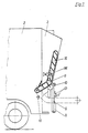
- FIGS. 1 and 2 there is a lifting and tipping device for emptying garbage containers 1 into a garbage collection container 2 of a garbage truck with pouring device 3.
- the pouring device 3 can be designed as a single bed or as a double bed or twin bed, in the latter case with two independently tilting devices or lifting-tilting devices 4 working from each other.
- the lifting-tilting device 4 has a swivel arm 5 or a pair of swivel arms 5, on which a lift-tilt frame 6 by means of a four-bar linkage, not shown here leadership is appropriate.
- the lifting and tipping frame 6 is equipped in this example in accordance with the type of the container 1 to be emptied on its upper part with a support bar 7 reaching under the edge of the container 1 and on the lower part with an abutment element 8 lying against the wall of the container 1.
- the schematically illustrated hydraulic cylinder-piston arrangement 9 is used to raise and lower the lifting and tilting frame 6.
- the container 1 is locked by pressing the edge of the container by the support bar 7 against the abutments 10 attached to the swivel arms 5.
- the swivel arms 5 are driven by means of hydraulic cylinder-piston assemblies 11, which are designed as swivel motors in the example shown.
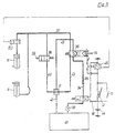
- the cylinder-piston unit 9 of the lifting device and the cylinder-piston unit 11 of the swivel motor of each lifting and tipping device 4 are integrated in a common power / pressure medium circuit (FIG. 3).
- This power-pressure medium circuit is designed such that the cylinder-piston unit 9 of the lifting device is acted upon at the start of work and then the cylinder-piston unit 11 provided for the swivel motor.
- the switch 12 which is provided for switching on the electrical control for automatic operation and is actuated by the container 1, is mounted on the side of the lifting / tilting frame 6 facing the container wall below the support bar 7.
- this switch it would also be possible to arrange this switch at other points on the lifting and tilting frame 6, for example in the region of the abutment part 8.
- a contact-free sensor or a light barrier or the like could also be provided.
- a manual control switch in addition to the switch 12 actuated by the container, for example a switch 13 which is on the Filling housing is placed in a location that is easy to reach by the operator.
- this manually operated switch 13 is combined with the control valve 36 arranged in the power pressure medium circuit in such a way that both parts have a common electromagnetic actuating device 36a and a common manual operating element 14.
- the manual control switch 13 is designed as a magnetic sensor switch, which is moved from one switch position to the other when the actuation rod axially guided by the electromagnetic actuation device 36a and the control valve 36 approaches.
- two barrier elements 15 are pivotally mounted on the side walls of the garbage truck. These barrier elements can be united in a bow-like manner on a common pivot shaft.
- the barrier elements & 15 can be pivoted by hand into and out of their securing position. They are held in their respective upper and lower positions by a holding spring 15b designed as a tension spring by exceeding a dead center position.
- a pressure medium motor 15a or a pair of pressure medium motors 15a are provided for adjusting the barrier elements 15.
- the barrier elements 15 actuate a switch 16 in their securing position.
- a hydraulic pressure medium system which is fed by the pressure medium pump 33, is provided for driving the lifting and tipping device 4.
- a pressure medium supply line 34 leads via a pressure medium check valve 35 to a control valve 36 designed as a two-position valve.
- a pressure medium supply line 37 is connected to this control valve 36, which leads to the pressure medium motors arranged in parallel, namely the lifting cylinder 9 and the swivel cylinder 11.
- a pressure relief valve 38 with an actuating element 39 is connected to the pressure medium supply line 37.
- a pressure medium relief line 40 leads to a pressure medium return valve 41 which is inserted into the pressure medium return line 42 in order to improve the pressure medium return and thus the backward movement of the cylinder-piston units 9 and 11.
- a bypass line 43 also leads from the control valve 36 to the pressure medium return valve 41.
- the pressure medium return line 42 leads into a pressure medium reservoir 43a, from which the pressure medium pump 33 sucks off the pressure medium quantity required for the system and introduces it via the pressure medium supply line 34 into the pressure medium power circuit.
- a control circuit which consists of the switch 12 attached to the lifting and tipping frame 6 and actuated by the attached container and a timing relay 45 connected in series with it.
- This timing relay 45 is connected to the electrical actuating device of the changeover valve 36 of the pressure medium power circuit.
- the time constant of the time relay 45 is set to such a time period that the lifting and tilting device requires from lifting, pivoting until the container is completely emptied.
- the two units are coordinated with one another with their piston cross-section so that they correspond accordingly the initial power to be provided by the respective unit of the lifting cylinder 9 is designed to be stronger than the swivel drive cylinder 11.
- the cylinder 9 is thus first actuated until the lifting process is almost complete and the tilting process is initiated by the swivel drive cylinder 11 due to the slight increase in pressure which occurs.
- the pressure relief valve 38 shown in FIG. 3 is of importance that, in the end tilt position, a pivot limiting lever set on the pivot shaft of the lifting and tilting device 4 and rotated in accordance with its pivoting strikes with its adjusting screw on the actuator 39 of the pressure relief valve 38.
- the pressure relief valve 38 which was previously in the closed position, is then brought into a partial opening position against the action of its adjusting spring, so that pressure relief in the pressure medium supply line 37 takes place via the pressure relief line 40 to the pressure medium return valve 41.
- the pressure relief valve 38 With a sufficiently large control distance between the actuation of the relief valve 38 and the end position of the swivel limiting lever, the pressure relief valve 38 is then opened to such an extent that a strong pressure drop occurs in the pressure medium supply line 34. This strong drop in pressure medium causes the lifting and tilting device with the container to be emptied to pivot back by such an amount that the pressure relief valve 38 is closed again.
- the inflowing pressure medium causes the lifting and tilting device to pivot again until the adjusting screw of the pivot limiting lever again hits the actuating element 39 of the pressure relief valve 38 and thus the pressure medium drop in the pressure medium supply line 37 when the pressure relief valve is open results in a corresponding pivoting back of the lifting and tilting device acts on the container to be emptied. In this way, a kind of shaking movement can be caused, so that a complete emptying of the container is ensured.
- the complete pivoting back and depositing of the container is initiated in that the time relay 45 interrupts the connection between the electrical actuating device of the changeover valve 36 and the current source 44 after the set period of time, whereby the changeover valve 36 is switched into the rest position by means of its return spring.
- the pressure medium coming from the pressure medium source 33 via the pressure medium supply line 34 then flows out via the bypass line 43 through the return valve 41, whereby it exerts a suction effect on the return line 42 and thus the backflow effect of the cylinders 9 and 11 via the pressure medium supply line 37 and the pressure medium return line 42 to increase pressure fluid flowing.
- a valve 80 is inserted in the flow of the pressure medium power circuit 37 to the cylinder-piston arrangement 11 to interrupt or restrict the pressure medium supply rhythmically.
- This valve 80 is switched on by the timing relay 45 at such a time when the tilting process has progressed to a desired extent. As a result, the container is set into a gentle shaking motion, resulting in a complete emptying of the container contents.
- the valve 80 is switched off by the timing relay 45 upon initiation of the swing-back process.
- switch 13 shown in FIG. 3 which is arranged in parallel to the switch 12 actuated by the container 1 attached to the lifting / tilting frame 6, it is the manual actuation switch for switching on the control circuit, as described for example in FIG. B. is arranged in Figure 1 or Figure 2.
- the emptying device When the emptying device is arranged on a refuse collection vehicle, it is expedient to use the vehicle battery as the power source 44. In the case of a stationary collecting container, it would also be conceivable to provide the control circuit with a mains connection.
- control valve 36 shown in FIG. 3 in the embodiment as a two-position valve it is also possible to use a three-position valve with a working, return and rest position.
- a three-position valve with a working, return and rest position.
- more complicated components of the control circuit or a more complex actuating element for such a switching valve such as. B. a second timing relay which, after opening the switching contact by the first, that is after the container has been emptied, brings the three-position changeover valve into the return position by means of the actuating device.
- a two-position shut-off valve 34a is inserted into the pressure medium supply line 34, and its electromagnetic actuation device is connected to the electrical control circuit via the switch 16 actuated by the barrier element 15.
- the switch 16 When the switch 16 is closed, the shut-off valve 34a is inserted into the position shown in FIG. 3, in which it clears the passage for the hydraulic pressure medium to the pressure medium feed line 34.
- the switch 16 When the switch 16 is open, the shut-off valve 34a moves under the action of its spring into the second position, in which a bypass line 43b leading back to the pressure medium reservoir 43a is connected to the pressure side of the pump 33.
- the emptying device according to Figure 1 or Figure 2 as a twin or double fill formed, that is equipped with two side-by-side lift-and-tilt devices 4, then two identical control systems can be provided as in FIG. 3, namely one for each lift-and-tilt device 4.
- a controller according to FIG. 5 can also preferably be used.
- the mode of operation of the twin or double bed is as follows, the corresponding components from FIG. 3 and FIG. 5 being provided with the same reference numerals, but additionally with letters a) and b) in FIG. 4:
- both pressure medium power circuits have a common pressure medium pump, which is followed by a pressure-independent pressure medium flow divider 46, so that each pressure medium power circuit has its own pressure medium source.
- a common current source 44 is also expediently provided for each of the two control circuits.
- each of the two individual lifting and tilting devices does not act directly on the control valve 36a, 36b of the power pressure medium circuit, but instead controls a pneumatic control pressure medium circuit.
- Each of these two control pressure medium circuits consists of a changeover valve 47a, 47b which is set up for electrical actuation and is connected to the corresponding control circuit and is connected to a feed line 48a, 48b.
- This pneumatic control pressure medium line 48a, 48b is connected to a working cylinder 49a, 49b under the action of a return spring, the piston rod 50a, 50b of which serves as an actuating element of the control valve 36a, 36b.
- a common pressure medium source 50 is provided for both pneumatic control pressure medium circuits and is connected to the pneumatic valves 47a, 47b via the branch lines 51a, 51b.
- the pneumatic pressure medium source already available for the brake system of the vehicle can be used as the pressure medium source 50.
- the pneumatic valve 47a, 47b is held in the switching position for the time defined by the time relay 45a, 45b, so that the pneumatic cylinder 49a , 49b is acted upon by the compressed air flowing from the pressure medium source 50 via the control pressure medium line and thereby brings the control valve 36a, 36b of the corresponding power pressure medium circuit into the working position.
- the pressure medium supply to the hydraulically operated working cylinders 9a, 11a or 9b, 11b is thus released and the emptying process begins.
- the swinging-back and depositing process of the lifting and tilting frame with the now emptied container is again effected in that the time relay 45a, 45b interrupts the circuit between the pneumatic valve 47a, 47b set up for electrical actuation and the current source 44.
- the pneumatic valve 47a, 47b is brought into the neutral position by the restoring force of its spring, so that the pneumatic pressure medium source 50 is suspended from the pressure medium control circuit.
- the emptying device shown in FIG. 4 is a so-called combination bed with which both smaller waste containers and a larger container can be emptied.
- two lifting and tilting devices 17a, 17b arranged side by side are attached to the rear of the pouring device 18.
- Each of these lifting and tilting devices 17a, 17b is driven via its own (not shown) cylinder-piston arrangements with separate pressure medium power circuits, so that they can be actuated individually for emptying smaller containers.
- the mode of operation of the combined bed is comparable to that of two single beds, as explained above.
- the lifting device of each individual lifting and tipping device consists of the known four-bar system; which is assembled with the abutment plate 20a, 20b to form the lifting and tilting frame 21a, 21b.
- connection and support bar z. B. attached by means of screws.
- this connection and support bar 25 is formed on its upper side with tooth-like holding projections 26a, 26b arranged at intervals in order to be able to accommodate containers, for example garbage containers of various top edge configurations.
- an optionally usable, dashed intermediate buffer 27 could be provided, which would have to be arranged between the two abutment parts 20a, 20b.
- pivotable support arms 28a, 28b with mounting claws 29a, 29b for the carrying pins of these waste containers are additionally provided on the two lifting and tilting frames 21a, 21b.
- the switches actuated by the attached containers for switching on the control sequence are expediently positioned on the lifting and tilting frame 21a, 21b in such a way that they do not come into contact with the connecting and support beam 25, that is to say when the combination bed is being converted for synchronous operation of both individual beds for emptying larger containers the container wall.
- one of the two manual control switches 31a, 31 attached to the filling housing must be actuated.
- this manual control switch is used for manual operation of the two beds, that is to say when the two pressure medium circuits are separated, for manual control of the lifting and tilting devices 17a, 17b if the electrical controls for the automated operation should fail.
- two latching manual actuation switches 32a, 32b are provided on the collecting container housing 18. In this case, an additional step is required after the garbage container has been attached. Thereafter, however, the emptying process runs automatically, so that the operator is not tied to the location of the device during this period of time, as in the manual control of the emptying process.
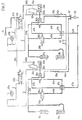
- FIG. 6 shows a schematic representation of a hydraulic drive system and electrical control system for a combination bed, as shown in FIG. 2.
- two hydraulic power pressure medium circuits are also provided in this combination bed, but are optionally separated or connected to one another via a changeover valve 53.
- Each of these pressure medium circuits has its own pressure medium source, which in the example shown can be formed by a branch 54a, 54b of a pressure-independent flow divider 54 in connection with a pressure medium pump 55 arranged upstream of this flow divider.
- a pressure medium supply line 56a, 56b leads from this pressure medium source 54a, 54b via a check valve 57a, 57b to the respective changeover valve 52a, 52b.
- This control valve 52a, 52b is connected in the neutral position to a bypass line 58a, 58b, which is connected to the pressure medium return line 60a, 60b via a pressure medium return valve 59a, 59b.
- the changeover valve 52a, 52b is connected to a pressure medium supply line 61a, 61b which conveys the hydraulic working medium to the pressure medium motors 62a, 63a and 62b, 63b arranged in parallel.
- a changeover valve 65 is inserted into the pressure medium supply line 61a between its connection to the pressure medium connecting line 64 of both pressure medium circuits and the control valve 52a, which is only switched into the shut-off position in synchronous operation of both beds. All other components of both power pressure medium circuits and control circuits are arranged in the same way.
- a pressure medium relief valve 66a, 66b with an actuating element 67a, 67b is connected to each pressure medium supply line 61a, 61b.
- Pressure medium relief lines 68a, 68b lead from these pressure medium relief valves 66a, 66b to the pressure medium guide valves 59a, 59b.
- the pressure medium power circuits are controlled by direct action on the changeover valve 52a, 52b set up for electrical actuation.
- the electrical control circuits each consist of a timing relay 69a, 69b, an actuation switch 70a, 70b attached to the lifting and tipping frame of each individual bed and a manual actuation element 71a, 71b connected in parallel therewith.
- a switch 74 actuated in the safety position of the barrier elements is inserted into the common connecting line 72 of both control circuits with the current source 73.
- a locking switch 75 is additionally arranged between this switch contact 74 and current source 73.
- the changeover valve 53 inserted in the connecting line 64 of the two pressure medium circuits and the changeover valve 65 used in the pressure medium feed line 61a of only one pressure medium circuit are set up for electrical actuation and together with the control current circles connected to the power source 73.
- Both changeover valves 53 and 65 are reversed, however, in such a way that the changeover valve 53 is in the blocking position and the changeover valve 65 is in the open position in the individual operation of both beds. In this operating case, the switch 75 is closed, that is, unlocked. If, on the other hand, the bolt is inserted or the connecting and support bar 25 is inserted, i.e.
- the switch contact 75 is opened, then the changeover valve 65 used in the pressure medium supply line 61a switches into the shut-off position by means of spring force and the changeover valve 53 used in the connecting line 64 into the open position by means of spring force, whereby a parallel connection of all pressure medium assemblies 62a, 62b, 63a, 63b is established and the emptying device is ready for synchronous actuation of both individual beds for emptying large containers.
- the changeover valve 52b must then be actuated manually by means of the actuator 76b.
- Both lift cylinders 63a, 63b and both swivel drive cylinders 62a, 62b are charged with the same pressure medium flow rate as in the case of individual control, only one lift cylinder 63a and one swivel drive cylinder 62a.
- a fully automatic emptying device can also be created within the scope of the invention, with which the emptying of containers of any size can be carried out automatically.
- a fully automatic emptying device is provided, for example, with a programming and switching device, on which identification information, such as type, size, installation location, etc., must be entered for the container to be emptied.
- identification information such as type, size, installation location, etc.
- Such a fully automatic device also contains in its control system a memory with data about the containers to be emptied. As a result, a circuit can be used to make a comparison between the entered identification information and the stored data.
- an emptying process suitable for the respective container or the control mode of the emptying device for this emptying process is then selected and set by means of switching devices on the respective control elements of the emptying device.
- the lifting and tipping frame or tipping frame can be brought into a presetting suitable for the container to be emptied, even before the emptying process begins. You can preselect the emptying speed.
- all parameters of the emptying process can be automatically selected and set up by this fully automatic device based on the data of the identified container and its contents.
- such a fully automatic device can be equipped with a device which controls the weight of the emptied container and which uses the emptying control and can repeat the emptying process if the weight of the emptied container is still above the target weight, that is to say a container has not been completely emptied.
Landscapes
- Engineering & Computer Science (AREA)
- Mechanical Engineering (AREA)
- Refuse-Collection Vehicles (AREA)
- Refuse Collection And Transfer (AREA)
- Refuse Receptacles (AREA)
- Drying Of Solid Materials (AREA)
- Control And Other Processes For Unpacking Of Materials (AREA)
- Filtering Of Dispersed Particles In Gases (AREA)
- Electrical Discharge Machining, Electrochemical Machining, And Combined Machining (AREA)
Priority Applications (1)
| Application Number | Priority Date | Filing Date | Title |
|---|---|---|---|
| AT85200470T ATE35122T1 (de) | 1984-02-20 | 1985-02-15 | Vorrichtung zum entleeren von behaeltern, insbesondere muellbehaeltern. |
Applications Claiming Priority (2)
| Application Number | Priority Date | Filing Date | Title |
|---|---|---|---|
| DE3405997A DE3405997C2 (de) | 1984-02-20 | 1984-02-20 | Vorrichtung zum Entleeren von Behältern, insbesondere von Müllbehältern in Sammelbehälter |
| DE3405997 | 1984-02-20 |
Publications (3)
| Publication Number | Publication Date |
|---|---|
| EP0156445A2 EP0156445A2 (de) | 1985-10-02 |
| EP0156445A3 EP0156445A3 (en) | 1986-03-19 |
| EP0156445B1 true EP0156445B1 (de) | 1988-06-15 |
Family
ID=6228219
Family Applications (2)
| Application Number | Title | Priority Date | Filing Date |
|---|---|---|---|
| EP85200470A Expired EP0156445B1 (de) | 1984-02-20 | 1985-02-15 | Vorrichtung zum Entleeren von Behältern, insbesondere Müllbehältern |
| EP85901399A Pending EP0173727A1 (de) | 1984-02-20 | 1985-02-15 | Vorrichtung zum entleeren von behältern, insbesondere müllbehältern |
Family Applications After (1)
| Application Number | Title | Priority Date | Filing Date |
|---|---|---|---|
| EP85901399A Pending EP0173727A1 (de) | 1984-02-20 | 1985-02-15 | Vorrichtung zum entleeren von behältern, insbesondere müllbehältern |
Country Status (14)
| Country | Link |
|---|---|
| US (1) | US4722656A (pt) |
| EP (2) | EP0156445B1 (pt) |
| JP (1) | JPH07112881B2 (pt) |
| AT (1) | ATE35122T1 (pt) |
| AU (1) | AU573811B2 (pt) |
| CA (1) | CA1259959A (pt) |
| CS (1) | CS275990B6 (pt) |
| DD (1) | DD233355A5 (pt) |
| DE (1) | DE3405997C2 (pt) |
| ES (1) | ES8606174A1 (pt) |
| GR (1) | GR850433B (pt) |
| PT (1) | PT79991B (pt) |
| WO (1) | WO1985003689A2 (pt) |
| ZA (1) | ZA851246B (pt) |
Cited By (5)
| Publication number | Priority date | Publication date | Assignee | Title |
|---|---|---|---|---|
| EP0386569A1 (de) * | 1989-03-08 | 1990-09-12 | OTTO LIFT-SYSTEME GmbH | Vorrichtung zum Entleeren von insbesondere Müllbehältern |
| EP0391225A1 (de) * | 1989-04-03 | 1990-10-10 | Zöller-Kipper GmbH | Sicherheitsschaltanordnung für Hubkipp- oder Kippvorrichtungen |
| NL8902431A (nl) * | 1989-09-29 | 1991-04-16 | Terberg Machines | Transportvoertuig met een containerlosinrichting. |
| BE1005209A5 (nl) * | 1991-08-29 | 1993-05-25 | All Round Consulting | Kunststofcontainer voor afval voorzien van een identificatiemiddel en apparaat voor het lezen van de daarin opgeslagen identificatiecode. |
| BE1013780A3 (nl) * | 2000-10-17 | 2002-08-06 | Mol Cy N V | Beveiligde inrichting voor het ledigen van afvalhouders in een verzamelhouder. |
Families Citing this family (43)
| Publication number | Priority date | Publication date | Assignee | Title |
|---|---|---|---|---|
| US5004392A (en) * | 1984-02-20 | 1991-04-02 | Zoller-Kipper Gmbh | Device for emptying containers, especially refuse bins |
| US5631835A (en) * | 1984-04-27 | 1997-05-20 | Hagenbuch; Leroy G. | Apparatus for identifying containers from which refuse is collected and compiling a historical record of the containers |
| US5416706A (en) * | 1984-04-27 | 1995-05-16 | Hagenbuch; Leroy G. | Apparatus for identifying containers from which refuse is collected and compiling a historical record of the containers |
| DE3447648C2 (de) * | 1984-12-28 | 1986-12-11 | Garbade, Rolf, 2804 Lilienthal | Verfahren und Vorrichtung zur gewichtsmäßigen Erfassung von Material, vorzugsweise Müll, bei der Entleerung in ein Sammelfahrzeug |
| DE3517491A1 (de) * | 1985-05-15 | 1986-11-20 | G + S Umwelttechnik GmbH, 7107 Nordheim | Hub- oder hub-kipp-vorrichtung zum entleeren von muellbehaeltern in muellfahrzeuge |
| ES2025105B3 (es) * | 1986-07-21 | 1992-03-16 | Zoller-Kipper Gmbh | Instalacion para vaciar contenedores |
| US4771837A (en) * | 1986-10-20 | 1988-09-20 | Breakthru Industries, Inc. | Weighing system |
| DE3735420A1 (de) * | 1987-10-20 | 1989-05-03 | Wuertz Geb Oswald Renate | Vorrichtung zum entleeren von behaeltern, insbesondere muellbehaeltern |
| DE3819169A1 (de) * | 1988-06-04 | 1989-12-07 | Pfister Gmbh | Verfahren und system zur waegung des inhalts von muelltonnen |
| DE3910791C2 (de) * | 1989-04-04 | 1994-08-11 | Bernd Dipl Ing Merle | Verfahren und Einrichtung zur Ermittlung von Entsorgungsgebühren |
| DE4128955C1 (pt) * | 1991-08-30 | 1992-11-05 | Zoeller Kipper | |
| GB2237791B (en) * | 1989-10-18 | 1994-01-26 | Waste Hoists Ltd | Collection vehicle, apparatus for use in the vehicle and method of collecting material |
| US5038876A (en) * | 1990-03-05 | 1991-08-13 | Wray-Tech Instruments, Inc. | Hydraulic control system for weighing |
| US5064008A (en) * | 1990-03-05 | 1991-11-12 | Wray-Tech Instruments, Inc. | Hydraulic control system for weighing |
| DE4010065A1 (de) * | 1990-03-29 | 1991-10-02 | Franz Sperner | Verfahren zum mengenbezogenen entsorgen von haushalts-und gewerbemuell und mengenbezogenes entsorgungssysstem fuer derartigen muell |
| US5056979A (en) * | 1990-05-25 | 1991-10-15 | Toter, Inc. | Lift unit for lifting and emptying waste containers |
| US5139101A (en) * | 1991-04-10 | 1992-08-18 | Wray-Tech Instruments, Inc. | Hydraulic control system for weighing and two-way valve therefor |
| DE4134344A1 (de) * | 1991-10-17 | 1993-04-22 | Wds Wiege Und Datensysteme Gmb | Vorrichtung zum gewichtsmaessigen erfassen von material, vorzugsweise muell, an einem sammelfahrzeug |
| DE4136045C2 (de) * | 1991-11-01 | 1993-10-07 | Zoeller Kipper | Sicherheitsschranke |
| US5879015A (en) * | 1992-02-10 | 1999-03-09 | Ramsey; Michael P. | Method and apparatus for receiving material |
| DE9206606U1 (de) * | 1992-05-15 | 1992-07-23 | Zöller-Kipper GmbH, 6500 Mainz | Trittbrett für Müllfahrzeuge |
| DE4234995C1 (en) * | 1992-10-16 | 1993-09-23 | Kellner, Rainer, 70825 Korntal-Muenchingen, De | Emptiness checking device for refuse containers - performs photoelectric detection of completion of flow of material out of upturned container into vehicle. |
| DE4415060C1 (de) * | 1994-04-29 | 1995-09-28 | Zoeller Kipper | Hubkipp- oder Kippvorrichtung zum Entleeren von Müllbehältern |
| DE4430833C1 (de) * | 1994-08-31 | 1995-11-23 | Zoeller Kipper | Verfahren und Vorrichtung zum Absichern des Arbeitsbereichs von Entleereinrichtungen |
| DE19536629C2 (de) * | 1995-09-22 | 2002-10-24 | Hilmar Meister | Verfahren und Vorrichtung zur Ermittlung verursachergerechter Müllentsorgungsgebühren in Großwohnanlagen |
| GB9702427D0 (en) * | 1997-02-06 | 1997-03-26 | Allen Jack Sales & Service | Hoist for refuse containers |
| NL1009325C2 (nl) * | 1998-06-05 | 2000-02-01 | Geesink Bv | Inrichting voor het legen van afvalhouders in een verzamelhouder |
| DK0962401T3 (da) * | 1998-06-05 | 2002-10-07 | Geesink Bv | Læssemekanisme for en affaldsbeholder forsynet med sikkerhedsorgan |
| EP1031520A1 (de) | 1999-02-22 | 2000-08-30 | Zöller-Kipper GmbH | Vorrichtung zum Entleeren von Behältern, insbesondere Müllbehältern |
| KR20070038042A (ko) * | 2004-05-14 | 2007-04-09 | 파세코 코퍼레이션 | 컨테이너 핸들러들을 위한 상황 보고 디바이스들을 만드는장치 및 방법 |
| DE102004036363B4 (de) * | 2004-07-22 | 2006-11-23 | Zöller-Kipper GmbH | Verfahren und Vorrichtung zur Absicherung des Arbeitsbereiches von Entleervorrichtungen |
| KR20070073938A (ko) * | 2004-10-27 | 2007-07-10 | 파세코 코퍼레이션 | 콘테이너 취급기의 상황 보고를 위한 라디오 위치 태그를이용하는 방법 및 장치 |
| US7253607B2 (en) * | 2005-04-29 | 2007-08-07 | Teradyne, Inc. | Site-aware objects |
| NL2004148C2 (nl) | 2010-01-26 | 2011-07-27 | Terberg Machines | Beladingssyssteem, vuilnisauto en werkwijze daarvoor. |
| NL2010344C2 (nl) * | 2013-02-22 | 2014-08-25 | Schijndel Holding B V Van | Inrichting en werkwijze voor het verwerken van vertrouwelijk materiaal. |
| DE102013223840A1 (de) | 2013-11-21 | 2015-05-21 | Zöller-Kipper GmbH | Sicherheitsvorrichtung |
| CN109264267A (zh) * | 2018-10-23 | 2019-01-25 | 凌丽霞 | 一种滑轮提升式垃圾回收车 |
| CN111284063B (zh) * | 2020-03-03 | 2021-11-12 | 福建龙马环卫装备股份有限公司 | 移动式垃圾压缩箱满箱判定方法 |
| WO2023004120A1 (en) | 2021-07-23 | 2023-01-26 | Micromatic Llc | Cart tipper protection device and process |
| WO2023073230A1 (en) * | 2021-10-31 | 2023-05-04 | Emdot Single Member Societe Anonyme | A system installable on a garbage truck for weighing garbage containers, a related use and a garbage truck |
| DE102023104795A1 (de) * | 2023-02-28 | 2024-08-29 | Zöller-Kipper Gesellschaft mit beschränkter Haftung | Schaltanordnung |
| DE102024106252A1 (de) | 2024-03-05 | 2025-09-11 | Faun Umwelttechnik Gmbh & Co. Kg | Nutzfahrzeug |
| DE202024101053U1 (de) | 2024-03-05 | 2024-05-08 | Faun Umwelttechnik Gmbh & Co. Kg | Nutzfahrzeug |
Family Cites Families (17)
| Publication number | Priority date | Publication date | Assignee | Title |
|---|---|---|---|---|
| NL105000C (pt) * | 1956-05-08 | |||
| DE1259237B (de) * | 1961-05-27 | 1968-01-18 | Niepmann & Co Maschf Fr | Vorrichtung zum Entleeren von Zigarettenbehaeltern |
| US3263842A (en) * | 1963-08-12 | 1966-08-02 | Schenley Distillers Co Inc | Case dumper |
| DE1228560B (de) * | 1965-06-18 | 1966-11-10 | Streuber Sulo Eisenwerk F | Steuervorrichtung fuer Muellgefaess-Hubkippvorrichtungen an Muellsammelwagen |
| FR1554603A (pt) * | 1966-11-18 | 1969-01-24 | ||
| US3599806A (en) * | 1969-12-04 | 1971-08-17 | Int Harvester Co | Bale wagon |
| AT302902B (de) * | 1970-01-02 | 1972-11-10 | Ochsner & Cie Ag J | Einrichtung zur staubfreien Entleerung von Kehrichteimern |
| GB1399454A (en) * | 1971-06-22 | 1975-07-02 | Shelvoke Drewry Ltd | Container lifting and tipping mechanism |
| US3738516A (en) * | 1972-07-31 | 1973-06-12 | L Wells | Container lifting mechanism |
| DE2721059A1 (de) | 1977-05-11 | 1978-11-23 | Severin Kuepper | Vorrichtung zum heben, entleeren und senken von muellbehaeltern oder containern |
| GB2005219B (en) * | 1977-09-13 | 1982-01-13 | Sperry Rand Nv | Agricultural bale accumulator |
| DE2847259A1 (de) * | 1978-10-31 | 1980-05-08 | Zoeller Kipper | Hub-kipp- oder kippvorrichtung zum entleeren von behaeltern unterschiedlicher groesse |
| DE2851084C2 (de) * | 1978-11-25 | 1982-09-30 | Fahrzeugbau Haller Gmbh, 7000 Stuttgart | Steuereinrichtung für eine Beladevorrichtung für Schüttgutbehälter |
| US4417839A (en) * | 1979-10-16 | 1983-11-29 | The United States Of America As Represented By The Secretary Of Agriculture | Automatic hatchery tray dumper |
| DE3123191A1 (de) * | 1980-06-11 | 1982-03-25 | Glover Webb & Liversidge Ltd., Hamble, Hampshire | Vorrichtung zum anheben und kippen von muellcontainern |
| DE3041630A1 (de) * | 1980-11-05 | 1982-05-13 | Schörling GmbH & Co Waggonbau, 3000 Hannover | Elektrohydraulische steuerung der belade-, press- und entleerungseinrichtung eines muellfahrzeuges |
| AU546853B2 (en) * | 1982-12-11 | 1985-09-26 | Satake Engineering Co. Ltd. | Grain handling system |
-
1984
- 1984-02-20 DE DE3405997A patent/DE3405997C2/de not_active Expired
-
1985
- 1985-02-15 AU AU41112/85A patent/AU573811B2/en not_active Ceased
- 1985-02-15 EP EP85200470A patent/EP0156445B1/de not_active Expired
- 1985-02-15 US US06/788,939 patent/US4722656A/en not_active Expired - Lifetime
- 1985-02-15 AT AT85200470T patent/ATE35122T1/de not_active IP Right Cessation
- 1985-02-15 WO PCT/EP1985/000052 patent/WO1985003689A2/de not_active Ceased
- 1985-02-15 EP EP85901399A patent/EP0173727A1/de active Pending
- 1985-02-15 JP JP60501308A patent/JPH07112881B2/ja not_active Expired - Lifetime
- 1985-02-19 ZA ZA851246A patent/ZA851246B/xx unknown
- 1985-02-19 CS CS851162A patent/CS275990B6/cs not_active IP Right Cessation
- 1985-02-19 DD DD85273371A patent/DD233355A5/de not_active IP Right Cessation
- 1985-02-19 ES ES540519A patent/ES8606174A1/es not_active Expired
- 1985-02-19 GR GR850433A patent/GR850433B/el not_active IP Right Cessation
- 1985-02-20 CA CA000474757A patent/CA1259959A/en not_active Expired
- 1985-02-20 PT PT79991A patent/PT79991B/pt active IP Right Revival
Cited By (5)
| Publication number | Priority date | Publication date | Assignee | Title |
|---|---|---|---|---|
| EP0386569A1 (de) * | 1989-03-08 | 1990-09-12 | OTTO LIFT-SYSTEME GmbH | Vorrichtung zum Entleeren von insbesondere Müllbehältern |
| EP0391225A1 (de) * | 1989-04-03 | 1990-10-10 | Zöller-Kipper GmbH | Sicherheitsschaltanordnung für Hubkipp- oder Kippvorrichtungen |
| NL8902431A (nl) * | 1989-09-29 | 1991-04-16 | Terberg Machines | Transportvoertuig met een containerlosinrichting. |
| BE1005209A5 (nl) * | 1991-08-29 | 1993-05-25 | All Round Consulting | Kunststofcontainer voor afval voorzien van een identificatiemiddel en apparaat voor het lezen van de daarin opgeslagen identificatiecode. |
| BE1013780A3 (nl) * | 2000-10-17 | 2002-08-06 | Mol Cy N V | Beveiligde inrichting voor het ledigen van afvalhouders in een verzamelhouder. |
Also Published As
| Publication number | Publication date |
|---|---|
| CS8501162A2 (en) | 1991-06-11 |
| ES8606174A1 (es) | 1986-04-16 |
| CA1259959A (en) | 1989-09-26 |
| PT79991B (de) | 1986-10-28 |
| EP0156445A3 (en) | 1986-03-19 |
| ZA851246B (en) | 1985-10-30 |
| WO1985003689A2 (en) | 1985-08-29 |
| WO1985003689A3 (en) | 1985-10-24 |
| ES540519A0 (es) | 1986-04-16 |
| DE3405997C2 (de) | 1987-01-08 |
| PT79991A (de) | 1985-03-01 |
| GR850433B (pt) | 1985-05-13 |
| DD233355A5 (de) | 1986-02-26 |
| JPS61501266A (ja) | 1986-06-26 |
| CS275990B6 (en) | 1992-03-18 |
| AU573811B2 (en) | 1988-06-23 |
| US4722656A (en) | 1988-02-02 |
| EP0173727A1 (de) | 1986-03-12 |
| JPH07112881B2 (ja) | 1995-12-06 |
| ATE35122T1 (de) | 1988-07-15 |
| DE3405997A1 (de) | 1985-08-22 |
| AU4111285A (en) | 1985-09-10 |
| EP0156445A2 (de) | 1985-10-02 |
Similar Documents
| Publication | Publication Date | Title |
|---|---|---|
| EP0156445B1 (de) | Vorrichtung zum Entleeren von Behältern, insbesondere Müllbehältern | |
| DE2126780C3 (de) | Mullfahrzeug mit hinter dem Sammelbehalter gelegenem Einfullraum und einem trogförmigen Vorverdichtungs raum | |
| EP0391225B2 (de) | Sicherheitsschaltanordnung für Hubkipp- oder Kippvorrichtungen | |
| EP1101398B1 (de) | Vorrichtung zur Arretierung einer Ernteguttransporteinrichtung | |
| EP0513479B1 (de) | Prallbrecher und Verfahren zum Einstellen des Arbeitsspaltes | |
| EP0398877B1 (de) | Vorrichtung zum entleeren von behältern, insbesondere müllbehältern | |
| DE69506296T2 (de) | Mi Sicherheitssystem versehenes Müllsammelfahrzeug | |
| DE3448135C2 (en) | Apparatus for emptying containers, especially refuse containers | |
| WO1996032346A1 (de) | Vorrichtung zum sammeln, einladen und transportieren von müll | |
| DE4128955C1 (pt) | ||
| DE4430833C1 (de) | Verfahren und Vorrichtung zum Absichern des Arbeitsbereichs von Entleereinrichtungen | |
| EP0569927A2 (de) | Trittbrett für Müllfahrzeuge | |
| DE3722184C2 (de) | Vorrichtung zum entleeren von behaeltern | |
| EP0669270A1 (de) | Einrichtung für das gebührenpflichtige Erfassen des Zugangs zu einem Kehrichtsammelraum | |
| DE2851084A1 (de) | Beladevorrichtung fuer schuettgutbehaelter | |
| DE3517491A1 (de) | Hub- oder hub-kipp-vorrichtung zum entleeren von muellbehaeltern in muellfahrzeuge | |
| EP1321383B1 (de) | Müllsammelfahrzeug mit Klammeraufnahme für Müllsammelbehälter | |
| EP0386569A1 (de) | Vorrichtung zum Entleeren von insbesondere Müllbehältern | |
| DE4001717C2 (pt) | ||
| EP0686581B1 (de) | Kombinierte Verriegelungs- und Abstützvorrichtung für Müllbehälter | |
| DE2064073A1 (de) | Ladevorrichtung für einen Behälter | |
| EP0734347B1 (de) | Fahrbetriebssicherung für hubkippvorrichtungen | |
| DE29701297U1 (de) | Vorrichtung zum Verriegeln eines Behälters, insbesondere Müllbehälters | |
| DE2742401A1 (de) | Beladevorrichtung fuer schuettgutbehaelter, insbesondere muellwagensammelbehaelter | |
| DE1659595C (de) | Am unteren Ende eines Müllschachts angeordnete Vorrichtung zum Verdichten von Müll |
Legal Events
| Date | Code | Title | Description |
|---|---|---|---|
| PUAI | Public reference made under article 153(3) epc to a published international application that has entered the european phase |
Free format text: ORIGINAL CODE: 0009012 |
|
| AK | Designated contracting states |
Kind code of ref document: A2 Designated state(s): IT |
|
| PUAL | Search report despatched |
Free format text: ORIGINAL CODE: 0009013 |
|
| AK | Designated contracting states |
Kind code of ref document: A3 Designated state(s): IT |
|
| 17P | Request for examination filed |
Effective date: 19860401 |
|
| XX | Miscellaneous (additional remarks) |
Free format text: VERBUNDEN MIT 85901399.7/0173727 (EUROPAEISCHE ANMELDENUMMER/VEROEFFENTLICHUNGSNUMMER) DURCH ENTSCHEIDUNG VOM 16.04.87. |
|
| 17Q | First examination report despatched |
Effective date: 19870521 |
|
| D17Q | First examination report despatched (deleted) | ||
| GRAA | (expected) grant |
Free format text: ORIGINAL CODE: 0009210 |
|
| AK | Designated contracting states |
Kind code of ref document: B1 Designated state(s): AT BE CH FR GB IT LI NL SE |
|
| REF | Corresponds to: |
Ref document number: 35122 Country of ref document: AT Date of ref document: 19880715 Kind code of ref document: T |
|
| XX | Miscellaneous (additional remarks) |
Free format text: VERBUNDEN MIT 85901399.7/0173727 (EUROPAEISCHE ANMELDENUMMER/VEROEFFENTLICHUNGSNUMMER) DURCH ENTSCHEIDUNG VOM 16.04.87. |
|
| ITF | It: translation for a ep patent filed | ||
| GBT | Gb: translation of ep patent filed (gb section 77(6)(a)/1977) | ||
| ET | Fr: translation filed | ||
| PLBE | No opposition filed within time limit |
Free format text: ORIGINAL CODE: 0009261 |
|
| STAA | Information on the status of an ep patent application or granted ep patent |
Free format text: STATUS: NO OPPOSITION FILED WITHIN TIME LIMIT |
|
| 26N | No opposition filed | ||
| ITTA | It: last paid annual fee | ||
| EAL | Se: european patent in force in sweden |
Ref document number: 85200470.4 |
|
| REG | Reference to a national code |
Ref country code: GB Ref legal event code: IF02 |
|
| PGFP | Annual fee paid to national office [announced via postgrant information from national office to epo] |
Ref country code: GB Payment date: 20040202 Year of fee payment: 20 |
|
| PGFP | Annual fee paid to national office [announced via postgrant information from national office to epo] |
Ref country code: FR Payment date: 20040218 Year of fee payment: 20 |
|
| PGFP | Annual fee paid to national office [announced via postgrant information from national office to epo] |
Ref country code: NL Payment date: 20040223 Year of fee payment: 20 Ref country code: AT Payment date: 20040223 Year of fee payment: 20 |
|
| PGFP | Annual fee paid to national office [announced via postgrant information from national office to epo] |
Ref country code: BE Payment date: 20040225 Year of fee payment: 20 |
|
| PGFP | Annual fee paid to national office [announced via postgrant information from national office to epo] |
Ref country code: SE Payment date: 20040227 Year of fee payment: 20 Ref country code: CH Payment date: 20040227 Year of fee payment: 20 |
|
| PG25 | Lapsed in a contracting state [announced via postgrant information from national office to epo] |
Ref country code: LI Free format text: LAPSE BECAUSE OF EXPIRATION OF PROTECTION Effective date: 20050214 Ref country code: GB Free format text: LAPSE BECAUSE OF EXPIRATION OF PROTECTION Effective date: 20050214 Ref country code: CH Free format text: LAPSE BECAUSE OF EXPIRATION OF PROTECTION Effective date: 20050214 |
|
| PG25 | Lapsed in a contracting state [announced via postgrant information from national office to epo] |
Ref country code: NL Free format text: LAPSE BECAUSE OF EXPIRATION OF PROTECTION Effective date: 20050215 |
|
| BE20 | Be: patent expired |
Owner name: *ZOLLER-KIPPER G.M.B.H. Effective date: 20050215 |
|
| REG | Reference to a national code |
Ref country code: GB Ref legal event code: PE20 |
|
| REG | Reference to a national code |
Ref country code: CH Ref legal event code: PL |
|
| PG25 | Lapsed in a contracting state [announced via postgrant information from national office to epo] |
Ref country code: SE Free format text: LAPSE BECAUSE OF NON-PAYMENT OF DUE FEES Effective date: 20050323 |
|
| EUG | Se: european patent has lapsed | ||
| NLV7 | Nl: ceased due to reaching the maximum lifetime of a patent |
Effective date: 20050215 |
|
| BE20 | Be: patent expired |
Owner name: *ZOLLER-KIPPER G.M.B.H. Effective date: 20050215 |