EP0054763B1 - Dispositif d'entraînement pour une tête articulée, disposée à l'extrémité d'un bras de manipulateur - Google Patents
Dispositif d'entraînement pour une tête articulée, disposée à l'extrémité d'un bras de manipulateur Download PDFInfo
- Publication number
- EP0054763B1 EP0054763B1 EP81110010A EP81110010A EP0054763B1 EP 0054763 B1 EP0054763 B1 EP 0054763B1 EP 81110010 A EP81110010 A EP 81110010A EP 81110010 A EP81110010 A EP 81110010A EP 0054763 B1 EP0054763 B1 EP 0054763B1
- Authority
- EP
- European Patent Office
- Prior art keywords
- housing
- gear
- joint
- axis
- drive
- Prior art date
- Legal status (The legal status is an assumption and is not a legal conclusion. Google has not performed a legal analysis and makes no representation as to the accuracy of the status listed.)
- Expired
Links
Images

Classifications
-
- B—PERFORMING OPERATIONS; TRANSPORTING
- B25—HAND TOOLS; PORTABLE POWER-DRIVEN TOOLS; MANIPULATORS
- B25J—MANIPULATORS; CHAMBERS PROVIDED WITH MANIPULATION DEVICES
- B25J17/00—Joints
- B25J17/02—Wrist joints
- B25J17/0283—Three-dimensional joints
-
- B—PERFORMING OPERATIONS; TRANSPORTING
- B25—HAND TOOLS; PORTABLE POWER-DRIVEN TOOLS; MANIPULATORS
- B25J—MANIPULATORS; CHAMBERS PROVIDED WITH MANIPULATION DEVICES
- B25J19/00—Accessories fitted to manipulators, e.g. for monitoring, for viewing; Safety devices combined with or specially adapted for use in connection with manipulators
- B25J19/0008—Balancing devices
- B25J19/002—Balancing devices using counterweights
-
- B—PERFORMING OPERATIONS; TRANSPORTING
- B25—HAND TOOLS; PORTABLE POWER-DRIVEN TOOLS; MANIPULATORS
- B25J—MANIPULATORS; CHAMBERS PROVIDED WITH MANIPULATION DEVICES
- B25J9/00—Programme-controlled manipulators
- B25J9/02—Programme-controlled manipulators characterised by movement of the arms, e.g. cartesian coordinate type
- B25J9/04—Programme-controlled manipulators characterised by movement of the arms, e.g. cartesian coordinate type by rotating at least one arm, excluding the head movement itself, e.g. cylindrical coordinate type or polar coordinate type
- B25J9/046—Revolute coordinate type
-
- B—PERFORMING OPERATIONS; TRANSPORTING
- B25—HAND TOOLS; PORTABLE POWER-DRIVEN TOOLS; MANIPULATORS
- B25J—MANIPULATORS; CHAMBERS PROVIDED WITH MANIPULATION DEVICES
- B25J9/00—Programme-controlled manipulators
- B25J9/10—Programme-controlled manipulators characterised by positioning means for manipulator elements
- B25J9/102—Gears specially adapted therefor, e.g. reduction gears
- B25J9/1025—Harmonic drives
-
- Y—GENERAL TAGGING OF NEW TECHNOLOGICAL DEVELOPMENTS; GENERAL TAGGING OF CROSS-SECTIONAL TECHNOLOGIES SPANNING OVER SEVERAL SECTIONS OF THE IPC; TECHNICAL SUBJECTS COVERED BY FORMER USPC CROSS-REFERENCE ART COLLECTIONS [XRACs] AND DIGESTS
- Y10—TECHNICAL SUBJECTS COVERED BY FORMER USPC
- Y10T—TECHNICAL SUBJECTS COVERED BY FORMER US CLASSIFICATION
- Y10T74/00—Machine element or mechanism
- Y10T74/19—Gearing
- Y10T74/19023—Plural power paths to and/or from gearing
- Y10T74/19126—Plural drivers plural driven
- Y10T74/1913—Bevel
Definitions
- the invention relates to a gear arrangement for a joint head connected to the boom of a manipulator, which comprises a base housing rotatable about the longitudinal axis of the boom, a joint housing which is pivotally mounted on the base housing about a pivot axis which is transverse to the longitudinal axis, and a joint housing which is mounted transversely to its joint axis in the joint housing.
- the tool-receiving support body is made.
- the base housing corresponds to the outstretched arm, which can be rotated about its longitudinal axis.
- the joint housing corresponds to the hand, which can be pivoted about the wrist, that is to say about an axis transverse to the arm axis.
- the support body corresponds to the outstretched finger, which, according to its arrangement on the hand, also carries out the swiveling movement of the hand, but is also rotatable about its own longitudinal axis.
- the intermediate shaft is also arranged between the hinge axis and the support body, as a result of which a considerable distance between the hinge axis and the support body is required. Since the center of gravity of the tool attached to the support body must still be at a necessary distance from the support body, there is consequently a considerable lever arm from the mentioned center of gravity to the joint axis, which requires a higher torque for the pivoting of the joint housing (hand), which is due to the weight the intermediate shaft, its storage and its drive parts increases accordingly.
- the base housing (arm) is gripped by the articulated housing (hand) attached to it with considerable tension, which results in a bulky joint head, which makes it difficult to move the tool attached to the support body to hard-to-reach places.
- the joint housing (hand) is encompassed by the base housing (arm) in an equally expansive manner, because two relatively parallel joint to the longitudinal axis extend between the relatively narrow joint housing and the side wall of the base housing There are intermediate shafts, which bring about the output of the joint housing and the supporting body via spur and bevel gears.
- the reduction gears are provided on the drive side, which also leads to the play of the individual gear parts being superimposed.
- the invention has for its object to find a gear arrangement for a joint head connected to the boom of a manipulator, which allows a much more precise execution of the calculated movements, a smaller torque for the pivoting movement of the joint housing and a slimmer design of the joint head to achieve without that an additional effort in terms of transmission technology or difficulties in assembly and maintenance must be accepted.
- the hinge axis can be mounted at a minimal distance from the supporting body, as a result of which the lever arm, namely the distance of the hinge axis from the center of gravity of the tool, is reduced and the torque to be applied is reduced.
- the shafts arranged in the intermediate shaft axis and in the joint axis are divided and mutually supported, which made it possible to provide the output to the support body on one side of the intermediate shaft and the output to the joint housing on the other side of the intermediate shaft, the Intermediate shaft is mounted directly or indirectly in the base housing.
- the features of claim 3 have the advantage that the distance formed by two concentrically mounted bevel gears of different diameters between the ring gear of the smaller to that of the larger bevel gear can be used for the arrangement of a double bearing for the shorter intermediate shaft, the storage of which is therefore clear is determined. Consequently, the bevel gear guided in this double bearing can support the longer intermediate shaft with its hub, which consequently only requires a simple, space-saving bearing on the end shield.
- the same construction is also provided in the area of the joint axis. Both result in a not inconsiderable reduction in the joint head width.
- Claims 5 to 8 show the configuration of the transmission arrangement according to the invention on the side facing away from the joint head, based on the pivot bearing of the boom, which makes it possible to arrange the entire drive along the longitudinal axis of the boom, thereby articulating the boom in its center of gravity to store and balance the weight.
- the drive motors are housed directly in the housing guiding the base housing, which means that the longitudinal axis of the joint body is approximately at right angles to the extension arm, which consequently requires additional counterweights.
- claim 5 also has an independent inventive character, because its design makes it possible to arrange a joint head of a different design on the boom than the one designed according to the invention.
- the features of claim 6 give the advantage of limiting the maximum size of the movement to be generated on the drive side. With the aid of the reduction gears present in the drive housing, a movement image which is proportional or identical to the actual output movement is generated, which can be controlled and limited with the aid of end stops or the like.
- the features of claim 7 prove to be advantageous here because a smaller angular range of the control gear offers more space for the arrangement of limit switches or the like.
- the object of claim 8 has the consequence that the total weight of the boom can be reduced and special counterweights can be saved, because by dimensioning the drive housing and its design from e.g. Ductile iron forms the necessary counterweight to that of the joint head, so that the other housing parts can consist of light metal.
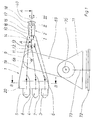
- the manipulator shown in FIG. 1 is based on a boom 1 which can be rotated about a horizontal pivot axis 9 and which is mounted on a link 69 which in turn can be rotated about the horizontal pivot axis 70 of the base body 71.
- This base body 71 is mounted on the foundation 72 about a vertical pivot axis 73.
- the axes 73, 70 and 9 thus result in three degrees of freedom, which are followed by a further three degrees of freedom, which are indicated by the movement arrows I and 111 on the boom 1.
- the boom 1 has a boom center piece 19 and a boom attachment housing 14 along the longitudinal axis 10, which are rigidly connected to one another and are mounted at 9 and can, for example, consist of light metal casting.
- a drive housing 20 is arranged on the boom 1, which in the exemplary embodiment is dimensioned and designed in such a way that it forms a counterweight to a joint head 2 arranged on the other side of the boom 1.
- the drive housing 20 can consist of nodular cast iron, for example.
- the drive motors 3, 4, 5 are connected, which are guided via universal joint shafts 6, 7, 8 to the drive shafts 11, 12, 13 on the extension arm housing 14. It is important to ensure that the central universal joint shaft 7 is laid somewhat eccentrically so that it can be guided past the shaft 68 which determines the swivel axis 9 at a short distance.
- the drive shafts 11, 13 drive coaxial hollow shafts 41, 79 (cf. FIG. 2).
- the drive shaft 12, coaxially supported in hollow shafts 41 and 79, continues tongue in shaft 33. Since no reduction is provided between the drive motors 3, 4, 5 and the drive shafts 11, 12, 13, the universal joint shafts 6, 7, 8 can be made small and weight-saving because of the low torque to be transmitted.
- the joint head 2 is guided on the extension arm housing 14.
- a base housing 15 is rotatably mounted in the attachment housing 14 about the longitudinal axis 10 and is driven by the motor 5 and the universal joint shaft 8, which results in the degree of freedom according to the arrow I.
- a joint housing 18 is pivotally mounted about the joint axis 17 and is driven by the motor 3 with the universal joint shaft 6, so that the degree of freedom of the joint housing 18 corresponds to the arrow 11.
- a support body 40 is mounted in the joint housing 18 about its longitudinal axis and driven via the motor 4 and the universal joint shaft 7, which leads to the degree of freedom according to arrow 111.
- joint head 2 denotes an intermediate shaft axis, the function of which is described in the exemplary embodiment in FIGS. 2 and 2a.
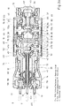
- Fig. 2 the drive trains for the base housing, the joint housing and the support body are shown symbolically. A clarification results from the enlarged illustration in FIG. 2a.
- the universal joint shaft 8 shown in FIG. 1 is connected to the drive shaft 13, which in turn is mounted in the extension arm housing 14.
- the output shaft 61 of the base housing 15 is driven via the gear wheels 58, 59, 60 being a reduction gear which sits on the output shaft 61 and permits a high reduction ratio to be generated.
- the reduction can be, for example, between 70: 1 and 120: 1.
- Conventional gears can be used for this purpose, for example as. Harmonic drive, cyclo gearbox or the like.
- the output shaft 61 is guided in the double bearing 74 on the shoulder housing 14. With the output shaft 61, the base housing 15 is rigidly connected, which essentially consists of the end plates 49, 51, 82, 83 forming the side walls, the cover walls 65 and 66 and the crosspiece 75. This base housing 15 is thus rotatable about the longitudinal axis 10 of the boom 1.
- the joint housing 18 is to be mounted and driven on the base housing 15 so as to be pivotable about the joint axis 17.
- the drive shaft 11 connected to the universal joint shaft 6 is used, which is mounted in the extension arm housing 14 and drives a hollow shaft 41 via the gears 62, -63, which in turn is mounted coaxially within the drive shaft 61 for the base housing 15.
- a bevel gear 42 which meshes with a bevel gear 43 rotating about the axis 16 (see FIG. 1).
- the shaft part 47a of the intermediate shaft 47 assigned to this bevel gear 43 is simply supported on one side in the bearing plate 49 of the base housing 15. The opposite storage will be described later.
- the shaft part 47a extends through the single bearing 48 of the bearing plate 49 and carries on the outside of the bearing plate 49 a belt wheel 52 which drives via a toothed belt drive 44 on a belt wheel 76 arranged concentrically to the hinge axis 17.
- a reduction gear 45 On the drive shaft part 55a connected to the belt wheel 76 there is a reduction gear 45, the reduction of which should also preferably be in the order of magnitude 70: 1 to 120: 1.
- the driven wheel of this reduction gear 45 is fixedly connected to the joint housing 18, whereas the drive shaft part 55a is rotatably mounted in the bearing plate 81 of the joint housing 18 in the bearing 57.
- the joint housing 18 is rotatably guided about the joint axis 17 via the bearings 46 on the base housing 15.
- the joint housing 18 protrudes outwards through an end recess of the base housing 15, the recess being designed in such a way that a large pivoting path of the joint housing 18 with its part projecting outwards is made possible about the joint axi
- the universal joint shaft 7 shown in FIG. 1 is connected to the drive shaft 12, 33 which is arranged coaxially to the longitudinal axis 10 and is mounted in the hollow shaft 41.
- a bevel gear 34 which interacts with the bevel gear 35 rotating about the intermediate shaft axis 16.
- This bevel gear 35 sits on the shorter shaft part 47b of the intermediate shaft 47.
- This shorter WeHentei! 47b is mounted in a tilt-free manner in the bearing plate 51 of the base housing 15 via a double bearing 50 and carries a belt wheel 53 on the outside of the bearing plate 51, which acts via the toothed belt drive 36 on a belt wheel 77 rotating about the joint axis 17.
- the hub of the bevel gear 35 seated on the shorter shaft part 47b carries a single bearing 54 in which the longer shaft part 47a of the intermediate shaft 47 is mounted.
- the double bearing 50 can be made compact by fully utilizing the free space formed by the difference in diameter of the bevel gears 42, 34, so that proper centering and guiding of the longer shaft part 47a is ensured. At the same time, considerable space is saved along the axis 16 of the intermediate shaft 47.
- the driven pulley 77 is seated on a shorter drive shaft part 55b of the drive shaft 55 rotating about the joint axis 17.
- This shorter drive shaft part 55b is in turn supported by a double bearing 64 in the bearing plate 80 of the joint housing 18 and carries a bevel gear 38 which is in contact with that on the drive shaft 67 of the Support body 40 seated bevel gear 37 cooperates.
- the hub of the bevel gear 38 can be used as a bearing 56 the longer drive shaft part 55a (the drive shaft of the joint housing 18) are formed.
- the drive shaft 67 of the support body 40 is mounted in the joint housing 18 and carries a reduction gear 39 to which the support body 40 is fastened on the output side.
- This support body 40 is in turn mounted in the part 78 of the joint housing 18 which projects beyond the base housing 15. In the basic position shown in FIG. 2, the support body 40 therefore executes a rotary movement about the longitudinal axis 10. However, since the support body 40 is mounted at 78 in the articulated housing 18, the support body 40 pivots with the articulated housing 18 about the articulation axis 17, so that when the support body 40 is pivoted out, it still does about the drive shaft 67, but no longer about the longitudinal axis 10 rotates.
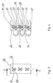
- FIG. 4 which shows a section C-C through the drive housing 20 according to FIG. 3, an arrangement is shown with the aid of which the individual movements of the base housing 15, the joint housing 18 and the support body 40 can be controlled and limited.
- the drive motors 3, 4, 5 are, as has already been shown in FIG. 1, connected to universal joint shafts 6, 7, 8.
- the end bearings 21, 22, 23 serve this purpose, in front of which toothed belt drives 24, 25, 26 are provided on the drive side, which act on control gears 27, 28, 29 with a strong reduction.
- switches 31, 32 which can be configured as limit switches. If such a limit switch 31, 32 is actuated, then the rotational or swiveling movement of the driven parts 15, 18, 40 can be limited due to the proportionality of the engine speed to the output speed.
- FIG. 3 shows the longitudinal section along the line B-B through the drive housing 20 according to FIG. 1 to clarify the position of the limit switches 31, 32 and the pivoting range of the cam 30.
Landscapes
- Engineering & Computer Science (AREA)
- Robotics (AREA)
- Mechanical Engineering (AREA)
- Manipulator (AREA)
- Jib Cranes (AREA)
- Gear-Shifting Mechanisms (AREA)
- Retarders (AREA)
- Gear Transmission (AREA)
- Resistance Welding (AREA)
Claims (8)
Priority Applications (1)
| Application Number | Priority Date | Filing Date | Title |
|---|---|---|---|
| AT81110010T ATE9289T1 (de) | 1980-12-19 | 1981-11-30 | Getriebeanordnung fuer einen mit dem ausleger eines manipulators verbundenen gelenkkopf. |
Applications Claiming Priority (2)
| Application Number | Priority Date | Filing Date | Title |
|---|---|---|---|
| DE3048067A DE3048067C2 (de) | 1980-12-19 | 1980-12-19 | Getriebeanordnung für den Gelenkkopf eines Manipulators |
| DE3048067 | 1980-12-19 |
Publications (3)
| Publication Number | Publication Date |
|---|---|
| EP0054763A1 EP0054763A1 (fr) | 1982-06-30 |
| EP0054763B1 true EP0054763B1 (fr) | 1984-09-12 |
| EP0054763B2 EP0054763B2 (fr) | 1989-10-04 |
Family
ID=6119712
Family Applications (1)
| Application Number | Title | Priority Date | Filing Date |
|---|---|---|---|
| EP81110010A Expired EP0054763B2 (fr) | 1980-12-19 | 1981-11-30 | Dispositif d'entraînement pour une tête articulée, disposée à l'extrémité d'un bras de manipulateur |
Country Status (9)
| Country | Link |
|---|---|
| US (1) | US4548097A (fr) |
| EP (1) | EP0054763B2 (fr) |
| JP (1) | JPS57121490A (fr) |
| AT (1) | ATE9289T1 (fr) |
| AU (1) | AU551501B2 (fr) |
| DD (1) | DD201988A5 (fr) |
| DE (2) | DE3048067C2 (fr) |
| ES (1) | ES507712A0 (fr) |
| SU (1) | SU1153817A3 (fr) |
Cited By (1)
| Publication number | Priority date | Publication date | Assignee | Title |
|---|---|---|---|---|
| DE102021003318A1 (de) | 2021-06-29 | 2022-12-29 | Günther Zimmer | Industrieroboter mit kompakt aufgebautem Achsantrieb |
Families Citing this family (57)
| Publication number | Priority date | Publication date | Assignee | Title |
|---|---|---|---|---|
| DE3228945A1 (de) * | 1982-08-03 | 1984-02-16 | GdA Gesellschaft für digitale Automation mbH, 8000 München | Vorrichtung zum antrieb der beiden achsen des handgliedes eines industrieroboters |
| JPS5973285A (ja) * | 1982-10-19 | 1984-04-25 | フアナツク株式会社 | 関節腕形の工業用ロボツト |
| JPS5973284A (ja) * | 1982-10-19 | 1984-04-25 | フアナツク株式会社 | 関節腕形の工業ロボツト |
| JPS5973297A (ja) * | 1982-10-20 | 1984-04-25 | フアナツク株式会社 | 工業用ロボツトの手首機構 |
| JPS5973298A (ja) * | 1982-10-20 | 1984-04-25 | ファナック株式会社 | 工業用ロボツトの手首機構 |
| US4624621A (en) * | 1982-10-21 | 1986-11-25 | Kabushiki Kaisha Kobe Seiko Sho | Wrist mechanism for industrial robots and the like |
| DE3370299D1 (en) * | 1982-11-02 | 1987-04-23 | Westinghouse Electric Corp | Robot wrist and arm |
| DE3244019C2 (de) * | 1982-11-27 | 1985-10-24 | Jungheinrich Unternehmensverwaltung Kg, 2000 Hamburg | Industrie-Roboter |
| DE3247789A1 (de) * | 1982-12-23 | 1984-06-28 | GASA-Produktion GmbH, 8752 Hösbach | Vorrichtung zum manipulieren eines gegenstandes |
| JPS59169790A (ja) * | 1983-03-14 | 1984-09-25 | 三菱電機株式会社 | 産業用ロボツト |
| JPS59175989A (ja) * | 1983-03-19 | 1984-10-05 | 日本シスコン株式会社 | マニピユレ−タの手首作動装置 |
| JPS6025676A (ja) * | 1983-07-21 | 1985-02-08 | 神鋼電機株式会社 | 多関節ロボツトのリミツトスイツチ機構 |
| ATE27561T1 (de) * | 1983-08-03 | 1987-06-15 | Kuka Schweissanlagen & Roboter | Getriebekopf fuer manipulatoren. |
| JPS6044288A (ja) * | 1983-08-16 | 1985-03-09 | 株式会社東芝 | 工業用ロボツトの手首装置 |
| JPS6044291A (ja) * | 1983-08-22 | 1985-03-09 | 株式会社東芝 | 工業用ロボツトの手首装置 |
| GB8327937D0 (en) * | 1983-10-19 | 1983-11-23 | Colne Robotics Co Ltd | Mechanical handling apparatus |
| US4637774A (en) * | 1984-02-29 | 1987-01-20 | Toyoda Koki Kabushiki Kaisha | Industrial robot |
| FR2560546A1 (fr) * | 1984-03-01 | 1985-09-06 | Toyoda Machine Works Ltd | Robot a articulations a fourches |
| JPS60191783A (ja) * | 1984-03-09 | 1985-09-30 | 豊田工機株式会社 | 関節形ロボツト |
| DE3480331D1 (en) * | 1984-08-03 | 1989-12-07 | Kuka Schweissanlagen & Roboter | Driven-tool holder head for manipulators |
| JPS6144591A (ja) * | 1984-08-07 | 1986-03-04 | 株式会社不二越 | ロボツト |
| SE444531B (sv) * | 1984-08-31 | 1986-04-21 | Asea Ab | Handled for en industrirobot |
| JPH0411027Y2 (fr) * | 1984-10-09 | 1992-03-18 | ||
| JPS61142086A (ja) * | 1984-12-13 | 1986-06-28 | メドマン株式会社 | 多関節型学習用ロボツト |
| DE3447701A1 (de) * | 1984-12-28 | 1986-07-10 | Kuka Schweissanlagen + Roboter Gmbh, 8900 Augsburg | Industrie-roboter fuer unterschiedliche einsatzzwecke |
| CA1244855A (fr) * | 1985-01-18 | 1988-11-15 | Kazuyuki Matsumoto | Organe moteur pour bras manipulateur sur robot |
| JPS62218087A (ja) * | 1985-01-18 | 1987-09-25 | 帝人製機株式会社 | 産業ロボットの関節駆動用減速装置 |
| JPH0618522B2 (ja) * | 1985-03-04 | 1994-03-16 | 花王株式会社 | 靴 底 |
| JPS61159190U (fr) * | 1985-03-23 | 1986-10-02 | ||
| DE8511948U1 (de) * | 1985-04-22 | 1985-07-11 | GdA Gesellschaft für digitale Automation mbH, 8000 München | Getriebeanordnung für eine Industrieroboterhand |
| JPH08390B2 (ja) * | 1985-07-05 | 1996-01-10 | 株式会社安川電機 | 産業用ロボツトの手首機構 |
| US4683772A (en) * | 1985-07-25 | 1987-08-04 | Westinghouse Electric Corp. | Hand gear train with three degrees of freedom |
| DE8525812U1 (fr) * | 1985-09-10 | 1987-02-19 | Manutec Gesellschaft Fuer Automatisierungs- Und Handhabungssysteme Mbh, 8510 Fuerth, De | |
| DE3545068A1 (de) * | 1985-12-19 | 1987-06-25 | Kuka Schweissanlagen & Roboter | Getriebekopf fuer manipulatoren |
| JPS62218088A (ja) * | 1986-03-18 | 1987-09-25 | 帝人製機株式会社 | 産業ロボットの関節駆動用減速装置 |
| JPH085026B2 (ja) * | 1986-04-15 | 1996-01-24 | 株式会社日立製作所 | 産業用ロボツト |
| SE453579B (sv) * | 1986-06-12 | 1988-02-15 | Asea Ab | Robothandled bestaende av tva handledshalvor |
| JPH0641117B2 (ja) * | 1986-06-13 | 1994-06-01 | 株式会社日立製作所 | ロボツトの手首装置 |
| DE3631024A1 (de) * | 1986-09-09 | 1988-03-17 | Mannesmann Ag | Roboterarm |
| DE3636514A1 (de) * | 1986-10-27 | 1988-05-05 | Fraunhofer Ges Forschung | Schraubvorrichtung |
| JPH04310384A (ja) * | 1991-04-09 | 1992-11-02 | Toyota Motor Corp | 複腕ロボット |
| DE3939836A1 (de) * | 1988-12-02 | 1990-06-07 | Tokico Ltd | Industrieroboter |
| JPH02190288A (ja) * | 1989-01-20 | 1990-07-26 | Kobe Steel Ltd | 工業用ロボット等の手首機構 |
| US5102280A (en) * | 1989-03-07 | 1992-04-07 | Ade Corporation | Robot prealigner |
| FR2667532B1 (fr) * | 1990-10-03 | 1998-05-15 | Commissariat Energie Atomique | Element de commande d'un bras de manipulation. |
| JP2590404B2 (ja) * | 1994-10-20 | 1997-03-12 | 帝人製機株式会社 | 産業ロボットの関節装置 |
| JP2561227B2 (ja) * | 1994-12-02 | 1996-12-04 | 帝人製機株式会社 | 産業ロボットの関節駆動用減速装置 |
| JPH106270A (ja) * | 1996-06-24 | 1998-01-13 | Fanuc Ltd | 産業用ロボット |
| DE19817606A1 (de) * | 1998-04-17 | 1999-10-21 | Kuka Roboter Gmbh | Vorrichtung zum Antrieb einer Roboterhand |
| RU2181669C1 (ru) * | 2001-07-02 | 2002-04-27 | Акционерное общество закрытого типа "Концерн Содружество" | Способ получения рельефной поверхности и устройство для его осуществления |
| FR2866826B1 (fr) * | 2004-02-26 | 2006-08-04 | Commissariat Energie Atomique | Bras de telemanipulation en deux parties |
| US8893578B2 (en) | 2009-02-13 | 2014-11-25 | Fanuc Corporation | Parallel robot provided with wrist section having three degrees of freedom |
| JP4659098B2 (ja) * | 2009-02-13 | 2011-03-30 | ファナック株式会社 | 3自由度を有する姿勢変更機構を備えたパラレルリンクロボット |
| KR101095690B1 (ko) | 2009-07-29 | 2011-12-20 | 창원대학교 산학협력단 | 3축 로봇 및 이를 이용한 갠트리형 공작 시스템 |
| CN102259337B (zh) * | 2010-05-28 | 2013-11-06 | 鸿富锦精密工业(深圳)有限公司 | 机器人臂部件 |
| CN103121217B (zh) * | 2011-11-21 | 2015-11-25 | 鸿富锦精密工业(深圳)有限公司 | 机器人臂部件 |
| DE102013225117A1 (de) | 2013-12-06 | 2015-06-11 | Richard Wolf Gmbh | Antriebsanordnung für ein endoskopisches Schaftinstrument |
Family Cites Families (21)
| Publication number | Priority date | Publication date | Assignee | Title |
|---|---|---|---|---|
| US2861699A (en) * | 1950-10-16 | 1958-11-25 | Gen Mills Inc | Method and apparatus for performing operations at a remote point |
| US2822094A (en) * | 1953-09-29 | 1958-02-04 | Greer Hydraulics Inc | Bridge manipulator |
| NL111065C (fr) * | 1959-08-31 | |||
| NL291905A (fr) * | 1962-04-25 | |||
| US3253995A (en) * | 1963-09-17 | 1966-05-31 | Gen Dynamics Corp | Rod handling equipment for nuclear reactor |
| DE2226407C3 (de) * | 1972-05-31 | 1978-10-12 | Industrie-Werke Karlsruhe Augsburg Ag, 7500 Karlsruhe | Gerät zur maschinellen, durch veränderbare Programme steuerbaren Handreichung |
| JPS5425300B2 (fr) * | 1973-01-25 | 1979-08-27 | ||
| JPS49124474U (fr) * | 1973-02-28 | 1974-10-24 | ||
| DE2330393C3 (de) * | 1973-06-15 | 1975-11-27 | Bruker-Physik Ag, 7501 Forchheim | Manipulator, insbesondere für Unterwasserfahrzeuge |
| DE2435156C2 (de) * | 1974-07-22 | 1983-09-01 | Kuka Schweissanlagen + Roboter Gmbh, 8900 Augsburg | Programmgesteuerter Manipulator |
| FR2310842A1 (fr) * | 1975-05-15 | 1976-12-10 | Renault | Tete pour robot ou manipulateur comportant au moins un axe de rotation |
| DE2654517B2 (de) | 1976-12-01 | 1979-09-27 | Siemens Ag, 1000 Berlin Und 8000 Muenchen | Manipulator |
| US4068536A (en) | 1976-12-23 | 1978-01-17 | Cincinnati Milacron Inc. | Manipulator |
| SU624788A1 (ru) * | 1977-04-22 | 1978-09-25 | Кировоградский институт сельскохозяйственного машиностроения | Привод робота |
| DE2717870C3 (de) * | 1977-04-22 | 1983-05-19 | Volkswagenwerk Ag, 3180 Wolfsburg | Handhabungsgerät |
| SU707793A1 (ru) * | 1977-07-01 | 1980-01-05 | Предприятие П/Я Р-6930 | Устройство дл оринтации захвата манипул тора |
| DE2908523A1 (de) * | 1979-03-05 | 1981-01-29 | Jungheinrich Unternehmensverw | Automatisches arbeitsgeraet |
| JPS5727686A (en) * | 1980-07-21 | 1982-02-15 | Hitachi Ltd | Industrial articular robot |
| JPH0547167A (ja) * | 1990-09-04 | 1993-02-26 | Canon Inc | 塵埃除去装置 |
| JPH05114653A (ja) * | 1991-10-23 | 1993-05-07 | Fujitsu Ltd | 半導体装置 |
| JPH073958B2 (ja) * | 1992-01-31 | 1995-01-18 | インターナショナル・ビジネス・マシーンズ・コーポレイション | 終端回路 |
-
1980
- 1980-12-19 DE DE3048067A patent/DE3048067C2/de not_active Expired
-
1981
- 1981-11-30 DE DE8181110010T patent/DE3166085D1/de not_active Expired
- 1981-11-30 AT AT81110010T patent/ATE9289T1/de active
- 1981-11-30 EP EP81110010A patent/EP0054763B2/fr not_active Expired
- 1981-12-02 US US06/326,762 patent/US4548097A/en not_active Expired - Lifetime
- 1981-12-04 ES ES507712A patent/ES507712A0/es active Granted
- 1981-12-11 DD DD81235681A patent/DD201988A5/de not_active IP Right Cessation
- 1981-12-15 SU SU813364456A patent/SU1153817A3/ru active
- 1981-12-16 JP JP56201715A patent/JPS57121490A/ja active Granted
- 1981-12-16 AU AU78561/81A patent/AU551501B2/en not_active Ceased
Cited By (1)
| Publication number | Priority date | Publication date | Assignee | Title |
|---|---|---|---|---|
| DE102021003318A1 (de) | 2021-06-29 | 2022-12-29 | Günther Zimmer | Industrieroboter mit kompakt aufgebautem Achsantrieb |
Also Published As
| Publication number | Publication date |
|---|---|
| AU551501B2 (en) | 1986-05-01 |
| AU7856181A (en) | 1982-09-23 |
| ES8304468A1 (es) | 1983-03-01 |
| EP0054763A1 (fr) | 1982-06-30 |
| JPS6158277B2 (fr) | 1986-12-10 |
| JPS57121490A (en) | 1982-07-28 |
| ES507712A0 (es) | 1983-03-01 |
| DD201988A5 (de) | 1983-08-24 |
| DE3048067A1 (de) | 1982-07-15 |
| ATE9289T1 (de) | 1984-09-15 |
| DE3048067C2 (de) | 1984-08-09 |
| EP0054763B2 (fr) | 1989-10-04 |
| SU1153817A3 (ru) | 1985-04-30 |
| DE3166085D1 (en) | 1984-10-18 |
| US4548097A (en) | 1985-10-22 |
Similar Documents
| Publication | Publication Date | Title |
|---|---|---|
| EP0054763B1 (fr) | Dispositif d'entraînement pour une tête articulée, disposée à l'extrémité d'un bras de manipulateur | |
| DE2751579C2 (de) | Motorgetriebener Manipulator | |
| EP0229941B1 (fr) | Tête de boîte de vitesse pour des manipulateurs | |
| DE3525806C2 (fr) | ||
| DE3939836C2 (fr) | ||
| DE8214938U1 (de) | Gelenkkopf für Industrieroboter | |
| DE3448409C2 (en) | Modular driving unit for industrial robot | |
| EP0133499B1 (fr) | Mécanisme pour manipulateurs | |
| EP0101569B1 (fr) | Dispositif d'actionnement des deux axes de poignet d'un robot industriel | |
| DE2845349C2 (de) | Hubschrauber mit zwei koaxialen, gegenläufigen Rotoren | |
| DE3719064A1 (de) | Roboterhandgelenk | |
| EP0527121A1 (fr) | Transmission pour entraînement d'une articulation notamment pour robot industriel | |
| DE2927485A1 (de) | Dreiachsgelenk fuer manipulatoren, roboter, handhabungseinrichtungen o.dgl. | |
| EP0121063B1 (fr) | Entraînement en rotation réglable sans jeu d'au moins un arbre principal pour manipulateurs | |
| EP0306660A2 (fr) | Dispositif d'entraînement d'un véhicule automobile | |
| DE3501798C2 (fr) | ||
| DE2937594A1 (de) | Uebertragungseinheit | |
| DE2910602A1 (de) | Einer arbeitsmaschine oder einem fahrzeugantrieb vorgeschaltetes planetengetriebe | |
| DE3050870C2 (fr) | ||
| DE2110012A1 (de) | Kegelrad Lagerung | |
| DE4115130A1 (de) | Uebertragungseinrichtung fuer fahrzeuge mit vierradanttrieb | |
| DE692113C (de) | Kranfahrzeug | |
| DE1775039B2 (de) | Antriebseinrichtung mit einem ritzel und einem zahnkranz | |
| DE894353C (de) | Getriebekasten fuer Kraftfahrdrehleitern | |
| DE967429C (de) | Schaufelradbagger |
Legal Events
| Date | Code | Title | Description |
|---|---|---|---|
| PUAI | Public reference made under article 153(3) epc to a published international application that has entered the european phase |
Free format text: ORIGINAL CODE: 0009012 |
|
| AK | Designated contracting states |
Designated state(s): AT CH DE FR GB IT LI SE |
|
| 17P | Request for examination filed |
Effective date: 19821112 |
|
| RAP1 | Party data changed (applicant data changed or rights of an application transferred) |
Owner name: KUKA SCHWEISSANLAGEN & ROBOTER GMBH |
|
| ITF | It: translation for a ep patent filed |
Owner name: STUDIO JAUMANN |
|
| GRAA | (expected) grant |
Free format text: ORIGINAL CODE: 0009210 |
|
| AK | Designated contracting states |
Designated state(s): AT CH DE FR GB IT LI SE |
|
| REF | Corresponds to: |
Ref document number: 9289 Country of ref document: AT Date of ref document: 19840915 Kind code of ref document: T |
|
| REF | Corresponds to: |
Ref document number: 3166085 Country of ref document: DE Date of ref document: 19841018 |
|
| ET | Fr: translation filed | ||
| PLBI | Opposition filed |
Free format text: ORIGINAL CODE: 0009260 |
|
| PLBI | Opposition filed |
Free format text: ORIGINAL CODE: 0009260 |
|
| PLBI | Opposition filed |
Free format text: ORIGINAL CODE: 0009260 |
|
| 26 | Opposition filed |
Opponent name: VOEST-ALPINE AKTIENGESELLSCHAFT Effective date: 19850518 |
|
| 26 | Opposition filed |
Opponent name: MANTEC GESELLSCHAFT FUER AUTOMATISIERUNGS- UND HAN Effective date: 19850607 |
|
| 26 | Opposition filed |
Opponent name: GDA GESELLSCHAFT FUER DIGITALE AUTOMATION MBH Effective date: 19850612 |
|
| PUAH | Patent maintained in amended form |
Free format text: ORIGINAL CODE: 0009272 |
|
| STAA | Information on the status of an ep patent application or granted ep patent |
Free format text: STATUS: PATENT MAINTAINED AS AMENDED |
|
| 27A | Patent maintained in amended form |
Effective date: 19891004 |
|
| AK | Designated contracting states |
Kind code of ref document: B2 Designated state(s): AT CH DE FR GB IT LI SE |
|
| ITF | It: translation for a ep patent filed |
Owner name: STUDIO JAUMANN |
|
| ET3 | Fr: translation filed ** decision concerning opposition | ||
| ITTA | It: last paid annual fee | ||
| PGFP | Annual fee paid to national office [announced via postgrant information from national office to epo] |
Ref country code: CH Payment date: 19931108 Year of fee payment: 13 |
|
| PGFP | Annual fee paid to national office [announced via postgrant information from national office to epo] |
Ref country code: AT Payment date: 19931126 Year of fee payment: 13 |
|
| PGFP | Annual fee paid to national office [announced via postgrant information from national office to epo] |
Ref country code: GB Payment date: 19941122 Year of fee payment: 14 |
|
| PG25 | Lapsed in a contracting state [announced via postgrant information from national office to epo] |
Ref country code: LI Effective date: 19941130 Ref country code: CH Effective date: 19941130 Ref country code: AT Effective date: 19941130 |
|
| EAL | Se: european patent in force in sweden |
Ref document number: 81110010.6 |
|
| REG | Reference to a national code |
Ref country code: CH Ref legal event code: PL |
|
| PGFP | Annual fee paid to national office [announced via postgrant information from national office to epo] |
Ref country code: DE Payment date: 19951019 Year of fee payment: 15 |
|
| PGFP | Annual fee paid to national office [announced via postgrant information from national office to epo] |
Ref country code: FR Payment date: 19951020 Year of fee payment: 15 |
|
| PGFP | Annual fee paid to national office [announced via postgrant information from national office to epo] |
Ref country code: SE Payment date: 19951116 Year of fee payment: 15 |
|
| PG25 | Lapsed in a contracting state [announced via postgrant information from national office to epo] |
Ref country code: GB Effective date: 19951130 |
|
| GBPC | Gb: european patent ceased through non-payment of renewal fee |
Effective date: 19951130 |
|
| PG25 | Lapsed in a contracting state [announced via postgrant information from national office to epo] |
Ref country code: SE Effective date: 19961201 |
|
| PG25 | Lapsed in a contracting state [announced via postgrant information from national office to epo] |
Ref country code: FR Effective date: 19970731 |
|
| PG25 | Lapsed in a contracting state [announced via postgrant information from national office to epo] |
Ref country code: DE Effective date: 19970801 |
|
| EUG | Se: european patent has lapsed |
Ref document number: 81110010.6 |
|
| REG | Reference to a national code |
Ref country code: FR Ref legal event code: ST |