WO2017164196A1 - 錠剤カセット用ロータ及び錠剤カセット - Google Patents
錠剤カセット用ロータ及び錠剤カセット Download PDFInfo
- Publication number
- WO2017164196A1 WO2017164196A1 PCT/JP2017/011300 JP2017011300W WO2017164196A1 WO 2017164196 A1 WO2017164196 A1 WO 2017164196A1 JP 2017011300 W JP2017011300 W JP 2017011300W WO 2017164196 A1 WO2017164196 A1 WO 2017164196A1
- Authority
- WO
- WIPO (PCT)
- Prior art keywords
- rotor
- tablet
- movable member
- gear
- guide path
- Prior art date
- Legal status (The legal status is an assumption and is not a legal conclusion. Google has not performed a legal analysis and makes no representation as to the accuracy of the status listed.)
- Ceased
Links
Images


Classifications
-
- G—PHYSICS
- G07—CHECKING-DEVICES
- G07F—COIN-FREED OR LIKE APPARATUS
- G07F17/00—Coin-freed apparatus for hiring articles; Coin-freed facilities or services
- G07F17/0092—Coin-freed apparatus for hiring articles; Coin-freed facilities or services for assembling and dispensing of pharmaceutical articles
-
- A—HUMAN NECESSITIES
- A61—MEDICAL OR VETERINARY SCIENCE; HYGIENE
- A61J—CONTAINERS SPECIALLY ADAPTED FOR MEDICAL OR PHARMACEUTICAL PURPOSES; DEVICES OR METHODS SPECIALLY ADAPTED FOR BRINGING PHARMACEUTICAL PRODUCTS INTO PARTICULAR PHYSICAL OR ADMINISTERING FORMS; DEVICES FOR ADMINISTERING FOOD OR MEDICINES ORALLY; BABY COMFORTERS; DEVICES FOR RECEIVING SPITTLE
- A61J7/00—Devices for administering medicines orally, e.g. spoons; Pill counting devices; Arrangements for time indication or reminder for taking medicine
- A61J7/0076—Medicament distribution means
-
- A—HUMAN NECESSITIES
- A61—MEDICAL OR VETERINARY SCIENCE; HYGIENE
- A61J—CONTAINERS SPECIALLY ADAPTED FOR MEDICAL OR PHARMACEUTICAL PURPOSES; DEVICES OR METHODS SPECIALLY ADAPTED FOR BRINGING PHARMACEUTICAL PRODUCTS INTO PARTICULAR PHYSICAL OR ADMINISTERING FORMS; DEVICES FOR ADMINISTERING FOOD OR MEDICINES ORALLY; BABY COMFORTERS; DEVICES FOR RECEIVING SPITTLE
- A61J3/00—Devices or methods specially adapted for bringing pharmaceutical products into particular physical or administering forms
-
- A—HUMAN NECESSITIES
- A61—MEDICAL OR VETERINARY SCIENCE; HYGIENE
- A61J—CONTAINERS SPECIALLY ADAPTED FOR MEDICAL OR PHARMACEUTICAL PURPOSES; DEVICES OR METHODS SPECIALLY ADAPTED FOR BRINGING PHARMACEUTICAL PRODUCTS INTO PARTICULAR PHYSICAL OR ADMINISTERING FORMS; DEVICES FOR ADMINISTERING FOOD OR MEDICINES ORALLY; BABY COMFORTERS; DEVICES FOR RECEIVING SPITTLE
- A61J7/00—Devices for administering medicines orally, e.g. spoons; Pill counting devices; Arrangements for time indication or reminder for taking medicine
- A61J7/0076—Medicament distribution means
- A61J7/0084—Medicament distribution means for multiple medicaments
Definitions
- the present invention relates to a tablet cassette provided in a tablet storage / dispensing apparatus, and relates to a tablet cassette rotor for storing a large number of tablets and taking out a required number of tablets according to a prescription, and a tablet cassette using the rotor.
- Tablet storage and dispensing devices installed in dispensing pharmacies and hospitals can automatically provide tablets according to prescriptions quickly, reliably and safely to many patients.
- There are many shapes and sizes of tablets such as a circle, an ellipse, a sphere, a capsule, and a sugar-coated tablet. It is desirable that the tablet storage and dispensing device can dispense as many kinds of tablets as possible.
- the tablet storage / dispensing device includes a large number of tablet cassettes that can store and discharge different types of tablets.
- Each tablet cassette is composed of a cassette main body for storing tablets and a rotor disposed on the bottom of the cassette main body so as to be rotatable.
- the rotor rotates, the tablets in the cassette body are sequentially guided to a plurality of tablet guide paths formed on the rotor, and when each tablet guide path coincides with the tablet discharge hole of the cassette body, The tablet and the tablet above it are partitioned by the partition member, and only the lowermost tablet is discharged from the tablet discharge hole.
- the present applicant has proposed a tablet cassette in Patent Document 1 that can change the width and depth of the tablet guide path of the rotor in accordance with the type of tablet.
- the tablet cassette of Patent Document 1 has a movable piece moving mechanism that moves a movable piece that forms a surface in the depth direction of the tablet guide path in the radial direction of the rotor, and a side wall that forms a surface in the width direction of the tablet guide path.
- a width adjusting mechanism for relatively moving the first and second movable members in the circumferential direction of the rotor and a plurality of tablet pressing members are provided along the tablet guide path, and one of the tablet pressing members is pressed by the pressing member. It has a tablet partitioning mechanism for discharging only the lowest tablet by holding the tablet above the lowest tablet. Since the tablet cassette of Patent Document 1 can adjust the depth, width, and partition position of the tablet guide path, it can handle tablets of many shapes and sizes.
- the present invention further improves the rotor of the tablet cassette of Patent Document 1, has a small number of parts, can handle tablets of a larger shape and size, and further has the depth, width, and partition position of the tablet guide path. It is an object of the present invention to provide a tablet cassette rotor and a tablet cassette that can be automatically adjusted.
- the present invention provides: (1) In a rotor that is rotatably accommodated in a cassette body that contains tablets, and has a plurality of tablet guide paths that guide the tablets in the cassette body to tablet ejection holes provided in the cassette body.
- the tablet guide path includes an inclined outer surface that is inclined with respect to the rotation axis of the rotor and is opposed to an inverted conical inclined inner surface of the cassette body,
- a rotor raising / lowering mechanism for raising and lowering at least the inclined outer surface of the rotor in the direction of the rotation axis of the rotor with respect to the cassette body; At least the inclined outer surface of the rotor is moved up and down by the rotor lifting mechanism so that the distance between the inverted conical inclined inner surface of the cassette body and the inclined outer surface of the tablet guide path can be adjusted.
- the distance between the inverted conical inclined inner surface of the cassette body and the inclined outer surface of the tablet guide path is increased, and conversely at least the rotor
- the distance between the inverted conical inclined inner surface of the cassette body and the inclined outer surface of the tablet guide path is reduced.
- the distance between the inverted conical inclined inner surface of the cassette body and the inclined outer surface of the tablet guide path is adjusted by raising and lowering the rotor according to the thickness of the tablet. be able to.
- the rotor is provided on a rotor base, and can be moved to the rotor base in the direction of the rotation axis of the rotor, and can rotate integrally with the rotor base around the rotation axis of the rotor.
- a rotor body having The rotor lifting mechanism is A screw hole provided on a rotation axis of the rotor in the rotor body; It is screwed into the screw hole of the rotor body, one end abuts on the rotor base, and the other end is a thickness adjusting member exposed from the rotor body, It is preferable to raise and lower at least the inclined outer surface of the rotor body. According to this, by rotating the thickness adjusting member to the left and right, the rotor main body having the screw hole screwed into the thickness adjusting member can be raised and lowered.
- the present invention provides: (3) A plurality of tablet guide paths that are rotatably accommodated in a cassette body that accommodates tablets and guide the tablets in the cassette body to tablet ejection holes provided in the cassette body, In the rotor in which the lowermost tablet and the upper tablet among the tablets aligned in the tablet guide path are partitioned by a partition member provided above the tablet discharge hole, A tablet support for supporting the lowest tablet of the tablet guide path; A tablet support raising / lowering mechanism for raising and lowering the tablet support; The distance between the partition member and the tablet support table can be adjusted by the tablet support table lifting mechanism.
- the distance between the partition member of the cassette body and the tablet support becomes smaller, and conversely, when the tablet support is lowered, the partition member The distance between the tablet and the tablet support is increased. For this reason, without changing the position of the partition member fixed to the cassette body, the distance between the partition member and the tablet support base, i.e., the tablet guide, is raised and lowered according to the height of the tablet. The partitioning position of the road can be adjusted.
- the rotor includes a rotor base and a rotor body provided so as to be integrally rotatable with the rotor base around a rotation axis of the rotor,
- the tablet support lifting mechanism is A rotating member provided on the rotor base, having a threaded portion formed at a lower outer periphery, and a driven gear formed at an upper inner periphery;
- An elevating member which is provided on the rotor base so as to be movable up and down, has the tablet support, and has a screw hole which is screwed with a screw portion of the rotating member; It is preferable that the drive gear at one end is engaged with the driven gear of the rotating member and the other end is a height adjusting member exposed from the rotor body.
- the driving gear of the height adjusting member rotates the rotating member via the driven gear of the rotating member and is screwed into the screw portion of the rotating member.
- the tablet support of the elevating member having the hole can be raised and lowered.
- the present invention provides: (5) In a rotor that is rotatably accommodated in a cassette body that accommodates tablets, and has a plurality of tablet guide paths that guide tablets in the cassette body to tablet discharge holes provided in the cassette body, A first movable member having a first vertical part that forms one side surface of the tablet guide path, and a first horizontal part that extends from the upper end of the tablet guide path toward the adjacent tablet guide path; A second movable member having a second vertical part forming the other side surface of the tablet guide path and a second horizontal part extending from the upper end of the tablet guide path toward the adjacent tablet guide path; A first support member disposed on the first movable member; A second support member disposed below the second movable member; A movable member moving mechanism that relatively rotates the first movable member and the second movable member; The movable member moving mechanism can adjust the distance between the first vertical portion and the second vertical portion.
- the first movable member and the second movable member are moved by the movable member moving mechanism so that the first vertical portion of the first movable member and the second vertical portion of the second movable member are relatively close to each other.
- the left and right widths of the tablet guide path are reduced, and the first movable member and the second movable member are arranged so that the first vertical portion of the first movable member and the second vertical portion of the second movable member are relatively separated from each other.
- the movable member is rotated, the left and right widths of the tablet guide path are increased. Therefore, by relatively rotating the first movable member and the second movable member in accordance with the size of the tablet, the distance between the first vertical portion and the second vertical portion, that is, the width of the tablet guide path. Can be adjusted.
- the movable member moving mechanism includes: A cam member rotatably disposed between the first movable member and the second movable member and having a driven gear; An adjustment hole provided in at least one of the first movable member and the second movable member; A first guide hole provided in the first support member and extending in a central line shape at an angle intersecting with the adjustment hole; A second guide hole provided in the second support member and coinciding with the first guide hole; A drive pin that fits into the adjustment hole, the first guide hole, and the second guide hole; A cam groove formed in the cam member and into which the drive pin is fitted; It is preferable that the drive gear at one end is engaged with the driven gear of the cam member, and the other end is a width adjusting member exposed from the rotor body.
- the movable member moving mechanism is A cam member rotatably disposed between the first movable member and the second movable member and having a driven gear; A first adjustment hole provided in the first movable member; A second adjustment hole provided in the second movable member and intersecting the first adjustment hole; A first guide hole provided in the first support member and extending in a center line shape at an angle intersecting the first adjustment hole and the second adjustment hole; A second guide hole provided in the second support member and coinciding with the first guide hole; A drive pin that fits into the first adjustment hole, the second adjustment hole, the first guide hole, and the second guide hole; A cam groove formed in the cam member and into which the drive pin is fitted; It is preferable that the drive gear at one end is engaged with the driven gear of the cam member, and the other end is a width adjusting member exposed from the rotor body.
- the cam member is rotated by rotating the width adjusting member left and right, and the cam of the cam member moves the drive pin in the radial direction of the rotor, so that the drive pin presses the first adjustment hole.
- the first movable member is rotated in one direction, and the drive pin presses the second adjustment hole to rotate the second movable member in the other direction.
- a 1st movable member and a 2nd movable member can be rotated relatively.
- the movable member moving mechanism includes: A segment worm gear provided on at least one of the first movable member and the second movable member; A transmission shaft having a worm meshing with the segment worm gear and a driven umbrella gear; It is preferable to have a drive bevel gear that meshes with the driven bevel gear at one end and a width adjusting member that is exposed from the rotor body at the other end.
- the movable member moving mechanism is A first segment worm gear provided on the first movable member; A second segment worm gear provided on the second movable member; A first transmission shaft having a first worm meshing with the first segment worm gear and a first driven bevel gear; A second transmission shaft having a second worm meshing with the second segment worm gear and a second driven bevel gear; It is preferable to have a drive bevel gear that meshes with the first driven bevel gear and the second driven bevel gear at one end, and a width adjusting member that is exposed from the rotor body at the other end.
- the width adjusting member left and right by rotating the width adjusting member left and right, the first worm rotates through the first driven umbrella gear, the second worm rotates through the second driven umbrella gear, and the first segment.
- the first movable member and the second movable member can be relatively rotated via the worm gear and the second segment worm gear.
- the movable member moving mechanism includes: A segment gear provided on at least one of the first movable member and the second movable member; It is preferable that a drive gear that meshes with the segment gear at one end and a width adjusting member that is exposed from the rotor body at the other end.
- the movable member moving mechanism is A first segment gear provided on the first movable member; A second segment gear provided on the second movable member; It is preferable that the first drive gear meshed with the first segment gear at one end and the second drive gear meshed with the second segment gear have a width adjustment member exposed at the other end from the rotor body. According to this, by rotating the width adjusting member left and right, the first movable member and the second movable member can be relatively rotated via the first segment gear and the second segment gear.
- the drive gear of the width adjusting member can be engaged with the segment gear via a reduction gear to enable fine adjustment and increase the resolution.
- the movable member moving mechanism includes: An A protrusion and a B protrusion provided on at least one of the first movable member and the second movable member; It is preferable that one end includes an A cam that slides on the A protrusion and a B cam that slides on the B protrusion, and the other end includes a width adjusting member that is exposed from the rotor body.
- the movable member moving mechanism is A protrusion and B protrusion provided on the first movable member; An A protrusion and a B protrusion provided on the second movable member; A first adjusting shaft having an A cam slidably contacting the A protrusion of the first movable member and a B cam slidably contacting the B protrusion; an A cam and the B protrusion slidably contacting the A protrusion of the second movable member; It is preferable that the first adjustment shaft and the second adjustment shaft include a width adjustment member that is interlocked with each other.
- the first adjustment shaft and the second adjustment shaft rotate in conjunction with each other, and the first adjustment shaft
- the A and B cams are in sliding contact with the A and B protrusions of the first movable member
- the A and B cams of the second adjustment shaft are in sliding contact with the A and B protrusions of the second movable member.
- the movable member and the second movable member can be relatively rotated.
- the rotor has a conical upper surface and an inverted conical outer peripheral side surface,
- the conical upper surface has a conical shape composed of a plurality of fan-shaped slopes,
- Each of the plurality of fan-shaped slopes is formed such that the inclination of one end in the circumferential direction is steeper than the inclination of the other end in the circumferential direction, and the height of the outer peripheral edge gradually increases in the direction opposite to the rotation direction of the rotor.
- it is.
- the rotor has a rotor cover placed on the rotor body, The plurality of fan-shaped slopes are preferably formed on an upper surface of the rotor cover. (14) It is preferable that the rotor cover is attracted to the rotor body by a magnet. (15)
- the rotor cover has an inverted conical outer peripheral surface continuous with an inverted conical outer peripheral surface of the rotor body, The lower end of the outer peripheral surface of the rotor cover has a plurality of engagement steps formed at equal intervals in the circumferential direction, and the plurality of engagement steps engage with a step formed on the upper end of the rotor body. It is preferable.
- the tablet cassette accommodates the rotor.
- the present invention provides a tablet guiding means for reliably guiding the tablet in the cassette body to the tablet pocket between the rotor and the cassette body.
- a tablet guiding means for reliably guiding the tablet in the cassette body to the tablet pocket between the rotor and the cassette body.
- a rotor having a plurality of tablet guide paths for guiding to The rotor has a conical upper surface and an inverted conical outer peripheral side surface
- the conical upper surface has a conical shape composed of a plurality of fan-shaped slopes,
- Each of the plurality of fan-shaped slopes has a radius at one end in the circumferential direction smaller than a radius at the other end in the circumferential direction, an inclination at one end in the circumferential direction is steeper than an inclination at the other end in the circumferential direction, It is formed so as to gradually become higher in the direction opposite to the direction.
- step difference which becomes large as it goes to radial direction outward between the said some fan-shaped slope.
- the rotor has a rotor cover placed on the rotor body, The plurality of fan-shaped slopes are preferably formed on an upper surface of the rotor cover.
- the rotor cover is attracted to the rotor body by a magnet.
- the rotor cover has an inverted conical outer peripheral surface continuous with an inverted conical outer peripheral surface of the rotor body, The lower end of the outer peripheral surface of the rotor cover has a plurality of engagement steps formed at equal intervals in the circumferential direction, and the plurality of engagement steps engage with a step formed on the upper end of the rotor body. It is preferable.
- the tablet cassette accommodates the rotor.
- the depth of the tablet guide path can be adjusted by moving the rotor up and down according to the thickness of the tablet by the rotor lifting mechanism.
- the tablet support base lifting mechanism can adjust the partition position of the tablet guide path by moving the tablet support base up and down according to the height of the tablet while fixing the partition member.
- the width of the tablet guide path can be adjusted by relatively rotating the first movable member and the second movable member in accordance with the size of the tablet by the movable member moving mechanism. Since these mechanisms are all provided in the rotor, they can be adjusted on the rotor side without adjusting the cassette body side. In particular, the position of the partition member provided in the cassette main body is fixed without changing, and the tablet support position below the partition member is raised and lowered to adjust the tablet partition position by the partition member.
- each tablet guide path Since the inclined outer surface, the tablet support base, and the first and second vertical protrusions constituting each tablet guide path are each composed of a single part for all tablet guide paths, the number of parts is small.
- the adjustment member exposed from the rotor body can adjust the depth, partitioning position and width of the tablet guide path according to the shape and size of the tablet, it can handle tablets of many shapes and sizes. Can do.
- the adjustment member since each adjustment member is exposed from the rotor body, the adjustment member is rotated according to the type of tablet having a different shape and size by using a device having a drive shaft that automatically drives each adjustment member. If the amount is set in advance, the depth, partition position, and width of the tablet guide path suitable for each tablet can be automatically adjusted.
- FIG. 2B is an exploded perspective view of the rotor of FIG. 2B.
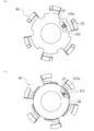
- the top view (a) of a rotor cover The top view (b, c) which shows the condition where the tablet on a rotor cover moves.
- Sectional drawing (a) which shows the condition where the tablet on a rotor cover moves Sectional drawing (b) which shows the condition where the tablet on the rotor cover in another Example moves.
- the disassembled perspective view of a movable member moving mechanism The perspective view (a) seen from the diagonal upper side of the 1st movable member, and the perspective view (b) seen from diagonally lower.
- the perspective view which shows the modification 1 of a movable member moving mechanism.
- the perspective view of the 2nd support member which has a worm mechanism.
- the disassembled perspective view which shows the modification of a rotor main body.
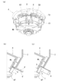
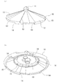
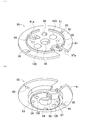
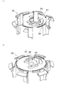
- FIG. 1 shows a tablet cassette 1 mounted on a tablet storage / dispensing device.
- the tablet cassette 1 includes a cassette body 3 provided on a base 2 and a rotor 4 according to the present invention housed in the cassette body 3.
- the cassette body 3 includes a tablet storage portion 5 that can store a large number of tablets T, and a rotor storage portion 6 that is provided below the tablet storage portion 5 and stores the rotor 4.
- the upper end of the tablet container 5 is open and can be opened and closed with a lid (not shown).
- the rotor accommodating portion 6 has an inverted conical upper inclined inner surface 6a, a cylindrical lower vertical inner surface 6b, and a bottom surface 6c.
- a tablet discharge hole 7 is formed from the lower portion of the upper inclined inner surface 6a to the bottom surface 6c.
- the tablet discharge hole 7 communicates with a tablet discharge path 2 a formed in the base 2.
- a partition member 8 is attached to the outside of the cassette body 3, and the tip of the partition member 8 is inserted from the outside of the rotor accommodating portion 6 to the inside.
- a rotor shaft hole 9 is formed in the center of the bottom surface 6c.
- the partition member 8 is formed in a circular arc shape having a convex upper surface.
- the partition member 8 ′ is formed in a flat plate shape instead of an arc shape, and the gap S ′ between the partition member 8 ′ and the lowest tablet T in the tablet guide path 4b is narrow.
- the tablet T may be caught by the partition member 8 ′ and not fall.
- the partition member 8 ′ hits the second tablet from the bottom and the second tablet from the bottom. The tablet cannot be partitioned smoothly.
- the partition member 8 is formed in an upward convex arc shape, as shown in FIG. 2A (c), the central portion of the partition member 8 becomes higher, and the partition member 8 and the tablet guide path 4b.
- the gap S between the lowermost tablet T and the lowermost tablet T becomes wider, and the lowermost tablet T can fall without being caught by the partitioning member 8.
- Both ends are lower than the central part, and the two functions of being able to smoothly partition the lowest tablet T1 and the second tablet T2 from the bottom can be sufficiently exhibited.
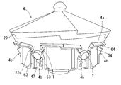
- the rotor 4 has a shape in which a top surface is conical, a side surface is an inverted conical shape, and a bottom surface is flat.
- Tablet pockets 4a are provided in the circumferential direction on the upper side surface of the rotor, and a plurality of tablet guide paths 4b extending downward from the tablet pocket 4a are provided at equal intervals in the circumferential direction.
- the tablet pocket 4a is formed by an outer peripheral surface of the rotor body 20 described later, a first horizontal protruding piece 54 of the first movable member 50 described later, and a second horizontal protruding piece 64 of the second movable member 60.
- the tablet T in the tablet housing part 5 of the cassette body 3 is received and aligned in the circumferential direction.
- the tablet guide path 4b includes a lower inclined outer surface 22c of the downward projecting portion 22 of the rotor body 20 described later, a first vertical projecting piece 53 of the first movable member 50 described later, and a second vertical projection of the second movable member 60 described later.
- the tablet 63 is formed by a piece 63 and a tablet support 47 of an annular elevating member 45, which will be described later, and is covered with the upper inclined inner surface 6a of the cassette body 3 and is aligned with the tablet pocket 4a and guided downward. .
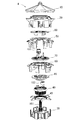
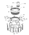
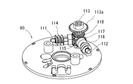
- FIG. 3 shows the rotor 4 in an exploded state.
- the rotor 4 mainly includes a rotor cover 10, a rotor body 20, a rotor base 30, a cylindrical rotating member 40, an annular lifting member 45, a first movable member 50, a second movable member 60, a cam member 70, and a first support member. 80, a second support member 90, a thickness adjusting screw 101, a height adjusting screw 102, and a width adjusting screw 103, and a rotor elevating mechanism, a tablet support elevating mechanism, and a movable member moving described below.
- the mechanism is configured.
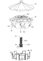
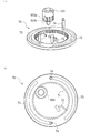
- FIG. 4 shows members constituting the rotor lifting mechanism.
- the rotor lifting mechanism includes a rotor cover 10, a rotor body 20, a rotor base 30, and a thickness adjustment screw 101.
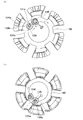
- the rotor cover 10 has an umbrella shape as a whole as shown in FIG.
- the upper surface of the rotor cover 10 is formed in a conical shape, and the outer peripheral surface is formed in an inverted conical shape.
- the rotor cover 10 is provided with a means for reliably guiding the tablet T accommodated in the cassette body 3 to the tablet pocket 4a.
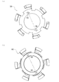
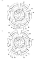
- the upper surface of the rotor cover 10 is composed of four fan-shaped inclined surfaces 12 that require a knob 11 located at the center.
- Each sector-shaped slope 12 is formed so that the radius (r1) is small at one end in the circumferential direction and the slope is steep, the radius (r2) is large at the other end in the circumferential direction, and the slope is relaxed. .
- the radius (r1) at one end in the circumferential direction of the sector-shaped slope 12 and the radius (r2) at the other end in the circumferential direction can be made the same.
- the height of the outer peripheral edge of the rotor cover 10 is gradually increased in the opposite direction (counterclockwise in FIG. 6A (a)) to the rotation direction of the rotor 4 (clockwise in FIG. 6A (a)). Is formed. For this reason, as shown in FIGS. 6A (b) and 6A (c), the rotor 4 rotates clockwise, and the tablet T located at the point A of the radius r1 near the outer periphery of the rotor cover 10 has the radius r2.
- the tablet T Since the tablet T is in contact with the inner surface of the cassette body 3 and receives resistance, the tablet T moves while sliding on the rotor cover 10 after the rotation of the rotor 4. As the tablet T rotates in the clockwise direction, the contact point between the outer peripheral edge of the rotor cover 10 and the tablet T moves from A to B obliquely above, as shown in FIG. That is, as the rotor cover 10 rotates clockwise, the tablet T is pushed upward by the outer peripheral edge of the rotor cover 10 and is pushed outward. As a result, the tablet T is laid down as indicated by a two-dot chain line. The direction is changed from the standing state to the standing state, and the tablet pocket 4a between the rotor 4 and the cassette body 3 is surely introduced.
- a step 13 is formed between the adjacent fan-shaped slopes 12 that increases in the radially outward direction.
- the tablet T accommodated in the cassette body 3 can be stirred.
- the large step 13 on the outer periphery of the rotor cover 10 can change the orientation of the tablet T from the sleeping state to the standing state as shown in FIG. 6B (a), and guide the tablet T to the tablet pocket 4a. Can do.
- the four fan-shaped slopes 12 are formed, the number is not limited and two or three may be sufficient.
- the tablet T accommodated in the cassette body 3 can be reliably guided to the tablet pocket 4a by the tablet guide means of the rotor cover 10, it can be guided to the tablet discharge hole 7 through each tablet guide path 4b and discharged. There is an effect that a predetermined number of tablets T can be smoothly discharged in a short time at regular time intervals one by one from each tablet guide path 4b.
- the tablet guide means of the rotor cover 10 can be applied to a general rotor that does not have a tablet guide path adjusting means by a rotor lifting mechanism, a tablet support lifting mechanism and a movable member moving mechanism. Further, this tablet guiding means can be applied even when the outer surface of the rotor body 20 is not an inverted conical shape but a cylindrical shape.
- the outer peripheral surface of the lower rotor body 20 is cylindrical from the inverted conical outer peripheral surface of the rotor cover 10 and the tablet guide path 4b extends in the vertical direction.
- the action of the fan-shaped slope 12 of the rotor cover 10 can reliably guide the tablet T to the tablet pocket 4a.
- the lower end of the outer peripheral surface of the rotor cover 10 is formed in a sawtooth shape, and engagement steps 14 are formed at six locations around the periphery.
- An annular rib 15 is formed on the inner surface of the rotor cover 10 as shown in FIG. Inside the annular rib 15, a magnetic metal plate 16 is attached to which a permanent magnet 27 of the rotor body 20 described later is attracted.
- the rotor body 20 includes a circular base portion 21, a downward projecting portion 22, an annular portion 23, and a guide portion 24.
- the base portion 21 is provided with a shaft portion 25 projecting downward from the center of the lower surface thereof, and a screw hole 25a is formed in the shaft portion 25.
- Permanent magnets 27 that are attracted to the metal plate 16 of the rotor cover 10 are mounted at two locations on the upper surface of the base 21.
- the downward projecting portions 22 extend downward from the six equidistant positions on the outer peripheral edge of the base portion 21.
- the downward projection 22 includes a vertical inner surface 22a, an upper inclined outer surface 22b inclined downward from the outer peripheral edge of the base 21, and a lower inclined outer surface 22c inclined downward inward from the lower end of the upper inclined outer surface 22b. It has a triangular shape when viewed from the side.
- the lower inclined outer surface 22c forms the bottom surface of the tablet guide path 4b.
- a slit 22 d is formed at the lower end of the downward projection 22.
- the annular portion 23 is concentrically formed on the outer side of the base portion 21 and is connected to the base portion 21 via the downward projecting portion 22.
- the outer surface of the annular portion 23 is formed in an inverted conical shape that is continuous with the outer peripheral surface of the rotor cover 10.
- An upper end of the annular portion 23 is formed in a sawtooth shape, and a step portion 28 that engages with the engagement step 14 of the rotor cover 10 and positions the rotor cover 10 in the circumferential direction is formed.
- the guide portion 24 extends downward between the downward projecting portions 22 and from the circumferentially equidistant position of the inner periphery of the annular portion 23.
- a guide groove 24 a is formed on the inner surface of the guide portion 24 so that a guide piece 32 of the rotor base 30 described later is slidably engaged. When the guide piece 32 and the guide groove 24a are engaged, the rotor base 30 and the rotor body 20 rotate integrally.
- the rotor base 30 has a circular base 31, a guide piece 32, and a drive shaft 33.
- a circular protrusion 34 is formed at the center, and an annular wall 35 is formed on the outside thereof.
- a recess 34 a that supports a thickness adjusting screw 101 described later is formed at the center of the circular protrusion 34.
- a hole 34b for accommodating the stopper 36 for preventing the thickness adjusting screw 101 from freely rotating, and a screw (not shown) inserted through two screw insertion holes 100 of the second support member 90 described later.
- Two screw holes 34c to be screwed are formed.
- An annular recess 37 is formed between the circular protrusion 34 and the annular wall 35 to accommodate a tablet support base lifting mechanism described later.
- annular wall 35 In the annular wall 35, vertical slits 35a extending in the axial direction are formed at six equal circumferential positions, and the vertical slits 35a are continuous with the horizontal slits 31a formed radially from the annular recess 37 to the outer peripheral edge of the base 31. .
- a plurality of reinforcing ribs 35b are provided at important points. As shown in FIG. 8B, a recess 31 b is formed in the center of the lower surface of the base 31.
- the guide pieces 32 are located at the same circumferential position on the outer periphery of the base 31 and project upward between the adjacent horizontal slits 31a.
- the guide piece 32 is formed so as to be slidably engaged with the guide groove 24 a of the guide portion 24 of the rotor body 20.
- the drive shaft 33 extends in the axial direction from the bottom center of the recess 31 b on the lower surface of the base 31.
- a drive gear 33 a shown in FIG. 1 is attached to the drive shaft 33 and is driven to rotate by a motor (not shown) provided on the base 2.
- the thickness adjusting screw 101 has a male screw portion 101a and a gear portion 101b at the lower end.
- the male screw portion 101 a is screwed into the screw hole 25 a of the rotor body 20, the lower gear portion 101 b is received and supported in the recess 34 a of the base portion 31 of the rotor base 30, and the upper end of the male screw portion 101 a extends from the screw hole 25 a of the rotor body 20. It protrudes and is exposed, and can be rotated from the outside.
- a tip of a stopper 36 made of an elastic piece is locked between the teeth of the gear portion 101b.
- a gear portion 101b at the lower end of the thickness adjusting screw 101 is formed larger than a hole 96 of a second support member 90 of a movable member moving mechanism described later, and the thickness adjusting screw 101 does not come out upward from the second support member 90. It is like that.
- FIG. 10 shows members constituting the tablet support base lifting mechanism.
- the tablet support raising / lowering mechanism includes a cylindrical rotating member 40, an annular raising / lowering member 45, and a height adjusting screw 102.
- the cylindrical rotating member 40 has a male screw portion 41 formed at the lower outer periphery and a driven gear 42 formed at the upper inner periphery.
- a stopper 43 that prevents the cylindrical rotating member 40 from freely rotating is engaged with the driven gear 42.
- annular elevating member 45 arms 46 project radially from six outer peripheral positions, and a tablet support 47 is formed at the tip of each arm 46.
- the tablet support 47 has an inclined surface 47a orthogonal to the tablet guide path 4b so that the lowest tablet T in the tablet guide path 4b can be supported.
- a female screw portion that is screwed with the male screw portion 41 of the cylindrical rotating member 40 is formed.
- the height adjusting screw 102 has a drive gear 102 a that meshes with the driven gear 42 of the cylindrical rotating member 40 at the lower end.
- the upper end of the height adjusting screw 102 protrudes from the hole 21a on the upper surface of the base portion 21 of the rotor main body 20, and can be adjusted for rotation from the outside.
- the cylindrical rotating member 40 and the annular elevating member 45 are screwed together and are accommodated in the annular recess 37 of the rotor base 30, and the arm 46 of the annular elevating member 45 is slidably fitted into the vertical slit 35 a of the rotor base 30.
- the tablet support 47 protrudes outside the annular wall 35 of the rotor base 30, and supports the lowest tablet T in the tablet guide path 4b.
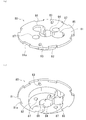
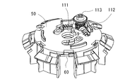
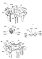
- FIG. 12 shows members constituting the movable member moving mechanism.
- the movable member moving mechanism includes a first movable member 50, a second movable member 60, a cam member 70, a first support member 80, a second support member 90, and a width adjustment screw 103.
- the first movable member 50 includes an annular base 51, six wall portions 52, a first vertical protrusion 53, and a first horizontal protrusion 54.
- Two first adjustment holes 55 are formed in the base 51 at positions separated by 180 degrees.
- the first adjustment hole 55 is a long hole, and its center line is inclined by 60 degrees with respect to a radial line passing through the center of the first movable member 50.
- notches 51 a with which the downward projecting portions 22 of the rotor body 20 engage are formed at six circumferentially spaced positions on the outer peripheral edge of the base 51.
- an arcuate guide portion 56 is annularly arranged on the lower surface of the base portion 51.
- the six wall portions 52 protrude downward from a position that is equidistant around the outer periphery of the base portion 51 and that is biased toward the left notch 51a when viewed from the front.
- the first vertical protrusion 53 protrudes outward from the left end when viewed from the front of the wall portion 52, and forms the right side surface of the tablet guide path 4b described above.
- the first vertical protrusion 53 is formed with a notch 53a into which the partition member 8 is fitted.
- the first horizontal protrusion 54 extends from the upper end of the first vertical protrusion 53 horizontally in the circumferential direction toward the right side when viewed from the front, and forms the bottom surface of the tablet pocket 4a described above.
- the upper surface of the tip of the first horizontal protrusion 54 is formed with a taper 54a that faces downward toward the tip.
- the second movable member 60 has an annular base 61, six wall parts 62, a second vertical protrusion 63, and a second horizontal protrusion 64.
- Two second adjustment holes 65 are formed in the base 61 at positions separated by 180 degrees.
- the second adjustment hole 65 is a long hole, and the center line of the second adjustment hole 65 is the center of the second movable member 60 in the direction intersecting the first adjustment hole 55 of the first movable member 50. Tilted 60 degrees with respect to the radial line through Returning to FIG.
- notches 61 a with which the downward projecting portions 22 of the rotor body 20 engage are formed at six circumferentially equidistant positions on the outer peripheral edge of the base 61.
- an arcuate guide portion 66 is annularly arranged on the upper surface of the base portion 61.
- the six wall portions 62 protrude downward from a position that is equidistant around the outer periphery of the base portion 61 and that is biased toward the notch 61a on the right side when viewed from the front.
- the second vertical protrusion 63 protrudes outward from the right end when viewed from the front of the wall portion, and forms the left side surface of the tablet guide path 4b described above.
- the second vertical protrusion 63 is formed with a notch 63a into which the partition member 8 is fitted.
- the second horizontal protrusion 64 extends from the upper end of the second vertical protrusion 63 in the circumferential direction horizontally toward the left side when viewed from the front, and together with the first horizontal protrusion 54 of the first movable member 50, the tablet described above.
- the bottom surface of the pocket 4a is formed.
- the tip of the second horizontal protrusion 64 of the second movable member 60 is formed so as to overlap the tip of the first horizontal protrusion 54 of the first movable member 50.
- the cam member 70 has an annular shape and is disposed between the first movable member 50 and the second movable member 60, and the guide portion 56 on the lower surface of the first movable member 50 and the first movable member 50. 2 It is guided by a guide part 66 on the upper surface of the movable part 60 and can rotate.
- a driven gear 71 is formed on the inner periphery of the cam member 70, and two arc-shaped cam grooves 72 are formed between the inner periphery and the outer periphery.
- a stopper 73 that prevents free rotation of the cam member 70 is engaged with the driven gear 71.
- the angle from one end to the other end of the cam groove 72 is about 140 °, but is not limited thereto.
- the cam groove 72 is formed so as to approach the outer peripheral edge as it proceeds in the clockwise direction when viewed from the plane.
- a drive pin 74 is inserted into each cam groove 72.
- the first support member 80 has a circular protrusion 82 on the lower surface of a circular base 81.
- Two first guide holes 83 are formed in the base portion 81 at positions separated by 180 °.
- the first guide hole 83 is a long hole and extends in the radial direction passing through the center of the first support member 80.
- the upper end of the drive pin 74 is fitted in the first guide hole 83.
- a notch 81 a with which the downward projecting portion 22 of the rotor main body 20 engages is formed at a circumferentially equidistant position on the outer peripheral edge of the base portion 81.
- a hole 84 through which the thickness adjusting screw 101 of the rotor lifting mechanism passes, a hole 85 through which the height adjusting screw 102 of the tablet support lifting mechanism passes, and a width adjusting screw 103 to be described later pass.
- a hole 86 and two screw insertion holes 87 are formed.
- the second support member 90 is formed with an annular protrusion 92 on the upper surface of a circular base 91 to which the circular protrusion 82 of the first support member 80 is fitted.
- a circular large protrusion 93 and a small protrusion 94 are provided on the lower surface of the base 91.
- the large protrusion 93 and the small protrusion 94 have a size that fits into the cylindrical rotating member 40 of the above-described tablet support base lifting mechanism.
- a second guide hole 95 is formed at a position corresponding to the first guide hole 83 of the first support member 80 at a position 180 degrees away from the outer side of the annular protrusion 92 on the upper surface.
- the second guide hole 95 is a long hole and extends in the radial direction passing through the center of the second support member 90.
- the lower end of the drive pin 74 is fitted in the second guide hole 95.
- 103 a hole 98 through which the support shaft 103b passes, two screw holes 99 into which screws (not shown) inserted into the two screw insertion holes 87 of the first support member 80 are screwed, and two screw insertion holes 100 are formed.
- the base 91 is formed with a through hole 91a into which the stopper 43 of the tablet support base lifting mechanism is fitted.
- the first support member 80 and the second support member 90 are connected to the first movable member 50, The second movable member 60 and the cam member 70 are integrated with each other. Further, by inserting and tightening a screw (not shown) from the screw insertion hole 100 of the second support member 90 into the screw hole 34c of the rotor base 30, the second support member 90 is fixed to the rotor base 30, and the second support The cylindrical rotating member 40 of the tablet support raising / lowering mechanism is held between the member 90 and the rotor base 30, and the movement in the axial direction is restrained.
- the width adjusting screw 103 has a drive gear 103a that meshes with the driven gear 71 of the cam member 70 in the middle, and a support shaft 103b protruding from the lower end.
- the upper end of the width adjusting screw 103 protrudes from the hole 21b on the upper surface of the base portion 21 of the rotor main body 20, and can be adjusted for rotation from the outside.
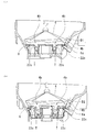
- a tablet pocket 4 a extending in the circumferential direction on the upper side of the rotor 4, and a plurality of tablets extending downward from the upper side of the rotor 4. It has a guideway 4b.
- the tablet pocket 4 a is a circumferential direction formed by the outer peripheral side surface formed by the outer peripheral surface of the rotor body 20, the first horizontal protruding piece 54 of the first movable member 50, and the second horizontal protruding piece 64 of the second movable member 60. And a bottom surface arranged at equal intervals.
- the tablet guide path 4b includes a bottom surface formed by the lower inclined outer surface 22c of the downward projecting portion 22 of the rotor body 20, a right side surface formed by the first vertical projecting piece 53 of the first movable member 50, and a second movable member. It is composed of a left side surface formed by 60 second vertical protrusions 63 and a lower end surface formed by the tablet support base 47.
- the tablet guide path 4 b extends from the adjacent tablet pocket 4 a toward the bottom surface of the rotor 4.
- the tablet T accommodated in the tablet accommodating portion 5 of the cassette body 3 enters the tablet pocket 4 a while being stirred by the step 13 of the rotor cover 10 by the rotation of the rotor 4.
- the tablet guide path 4b enters the tablet guide path 4b from 4a and approaches the tablet discharge hole 7, it is fixed to the cassette body 3 between the lowest tablet T in the tablet guide path 4b and the tablet T above it.
- the partition member 8 that has entered enters.
- the tablet T above the partition member 8 is prevented from falling downward by the partition member 8.
- the lowest tablet T below the partitioning member 8 is on the tablet support 47, but since the tablet support 47 has an inclined surface 47a, the tablet T falls on the inclined surface 47a toward the tablet discharge port 7, It is discharged from the tablet discharge hole 7.
- the tablet T discharged from the tablet discharge hole 7 is discharged through the tablet discharge path 2a of the base 2. Thereby, every time the tablet guide path 4b turns to the tablet discharge hole 7, the tablets T are discharged one by one. By adjusting the rotation angle of the rotor 4, the number of tablets T according to the prescription can be dispensed.
- the tablet guide path 4b uses the above-described rotor lifting mechanism, tablet support lifting mechanism, and movable member moving mechanism, the depth D corresponding to the thickness of the tablet T, the partition position H corresponding to the height of the tablet, the tablet The width W corresponding to the width of T can be adjusted. For this reason, according to the shape and magnitude
- the gear portion 101 b is restrained from moving in the axial direction by the second support member 90 and the rotor base 30, and the guide groove 24 a of the rotor body 20 is the guide piece of the rotor base 30. Since the rotor body 20 is restricted from rotating with respect to the rotor base 30 by engaging with the screw 32, when the thickness adjusting screw 101 is rotated, the male screw portion 101 a of the thickness adjusting screw 101 is screwed.
- the rotor body 20 having the screw holes 25a is raised or lowered in the direction of the rotation axis of the rotor 4. Along with this, the lower inclined outer surface 22c of the downward projecting portion 22 of the rotor body 20 forming the bottom surface of the tablet guide path 4b is also raised or lowered.
- the lower inclined outer surface 22 c of the downward projecting portion 22 is inclined from the outside to the inside in the radial direction from the top to the bottom, and the inverted conical shape of the rotor accommodating portion 6 of the cassette body 3 is formed. It is parallel to the upper inclined inner surface 6a.
- the lower inclined outer surface 22c of the downward projection 22 of the rotor body 3 is lowered, the lower inclined outer surface 22c of the downward projection 22 and the inverted conical upper inclination of the cassette body 3 are provided.
- the distance between the inner surface 6a is reduced, and the depth of the tablet guide path 4b can be reduced (D1).
- D1 the depth of the tablet guide path 4b
- the cylindrical rotating member 40 rotates.
- the cylindrical rotating member 40 is restrained from moving up and down by the second support member 90 and the rotor base 30.
- the annular elevating member 45 having the female threaded portion 48 that is screwed into the male threaded portion 41 of the cylindrical rotating member 40 has its arm 46 penetrating the vertical slit 35 a of the annular wall 35 of the rotor base 30, and is restricted from rotating. For this reason, the annular elevating member 45 is moved up and down by the rotation of the cylindrical rotating member 40, and the tablet support 47 of the annular elevating member 45 is moved up and down.
- the movable member moving mechanism in FIG. 12 is provided with a first adjustment hole 55 and a second adjustment hole 65 in the first movable member 50 and the second movable member 60 so that the first movable member 50 and the second movable member 60 are moved. Although it is rotated, an adjustment hole may be provided in either the first movable member 50 or the second movable member 60 so that either the first movable member 50 or the second movable member 60 is rotated.
- the shape and size of the tablet are rotated by rotating the thickness adjusting screw, the height adjusting screw, and the width adjusting screw.
- the tablet T can be discharged smoothly by adjusting the tablet guide path depth, height (partition position) and width suitable for the tablet. Since the rotation amount of the thickness adjustment screw, height adjustment screw, and width adjustment screw is proportional to the depth, height (partition position), and width of the tablet guide path, these adjustment operations can be performed automatically.
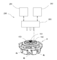
- a storage device 201 that stores the amount of rotation of the height adjustment screw 102 and the width adjustment screw 103, an input device 202 that inputs the type of tablet, a thickness adjustment screw 101, a height adjustment screw 102, and a width adjustment screw 103.
- An automatic adjustment device 200 including a driving device 203 that rotates is provided.
- the thickness adjustment screw 101 and the height from the storage device 201 are input according to the tablet type input to the input device 202.
- the rotation amounts of the adjustment screw 102 and the width adjustment screw 103 are read, and the thickness adjustment screw 101, the height adjustment screw 102, and the width adjustment screw 103 of the rotor 4 are rotated by the rotation amount by the drive device 203, so that the tablet It can be adjusted to a rotor 4 with a suitable tablet guide path 4b.
- This automatic adjustment device 200 is suitable not only for changing the type of tablet, but also for the rotor 4 in which the depth, height (partition position) and width of the tablet guide path 4b are shifted during use of the rotor 4 to an appropriate value. Can also be used to return to
- the movable member moving mechanism of the embodiment uses a cam mechanism for driving the first movable member 50 and the second movable member 60, but is not limited to the cam mechanism, and other mechanisms can be used. .
- other modifications of the movable member moving mechanism will be described.
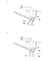
- FIG. 22 uses a worm mechanism for driving the first movable member 50 and the second movable member 60.
- the first movable member 50 is provided with a notch hole 57, and a protrusion 58 that protrudes downward is provided at the edge of the notch hole 57.
- a first segment worm gear 59 is formed in the first.
- the second movable member 60 is provided with a notch hole 67, and a protrusion 68 protruding upward is provided at the edge of the notch hole 67.
- a second segment worm gear 69 is formed on the protrusion 68.
- the first segment worm gear 59 and the second segment worm gear 69 are located on the same plane and have the same pitch circle when the first movable member 50 and the second movable member 60 are overlapped. It is formed to be on the top.
- a first transmission shaft 111, a second transmission shaft 112, and a width adjustment screw 113 are attached to the second support member 90.
- the first transmission shaft 111 has a first worm 114 that meshes with the first segment worm gear 59 in the middle, and a first driven bevel gear 115 at one end.
- the second transmission shaft 112 has a second worm 116 that meshes with the second segment worm gear 69 in the middle, and a second driven bevel gear 117 at one end.
- the first transmission shaft 111 and the second transmission shaft 112 are arranged at an angle of about 100 ° so that the driven bevel gears 115 and 117 approach each other.
- the width adjusting screw 113 has a drive umbrella gear 118 that meshes with the first driven umbrella gear 115 of the first transmission shaft 111 and the second driven umbrella gear 117 of the second transmission shaft 112 at the lower end, and a stopper (not shown) at the top. It has a gear portion 113a to be locked, and its upper end is exposed upward from the rotor body 20 and can be operated.
- the driving umbrella gear 118 of the width adjusting screw 113 drives the first driven umbrella gear 115 of the first transmission shaft 111 and the second driven umbrella gear 117 of the second transmission shaft 112. Then, the first transmission shaft 111 and the second transmission shaft 112 rotate.
- the second movable member 50 having the first segment worm gear 59 that meshes with the first worm 114 of the first transmission shaft 111 and the second segment worm gear 69 that meshes with the second worm 116 of the second transmission shaft 112.
- the movable members 60 rotate in opposite directions.
- interval of the 1st vertical protrusion 53 of the 1st movable member 50 and the 2nd vertical protrusion 63 of the 2nd movable member 60 ie, the width
- a spur gear mechanism can be used instead of the worm mechanism of FIG. That is, as shown in FIGS. 25A and 25B, the first segment gear 121 of the first movable member 50 and the second segment gear 122 of the second movable member 60 are formed to face each other.
- the width adjusting screw 123 is provided with a first drive gear 123 a that meshes with the first segment gear 121 of the first movable member 50 and a second drive gear 123 b that meshes with the second segment gear 122 of the second movable member 60.
- the width adjustment screw 123 When the width adjustment screw 123 is rotated left or right, the first movable member 50 having the first segment gear 121 that meshes with the first drive gear 123a of the width adjustment screw 123, and the second drive gear 123b of the width adjustment screw 123, The second movable member 60 having the meshing second segment gear 122 rotates in directions opposite to each other. Thereby, the space
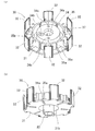
- FIG. 26 uses a double cam mechanism for driving the first movable member 50 and the second movable member 60.
- first movable member 50 two substantially semicircular cutouts 51 b and 51 c are formed adjacent to each other on the inner periphery of the annular base 51.
- An A protrusion 131a and a B protrusion 131b that are opposed to each other in the circumferential direction of the first movable member 50 are formed on the edge of the notch 51b that is located upstream in the clockwise direction when the first movable member 50 is viewed from above. Yes.
- the A protrusion 131a and the B protrusion 131b serve as cam followers that are in sliding contact with the A cam 134a and the B cam 134b of the first adjustment shaft 134, which will be described later.
- two substantially semicircular cutouts 61 b and 61 c are formed adjacent to the inner periphery of the annular base 61 in the second movable member 60.
- An A protrusion 132a and a B protrusion 132b that are opposed to each other in the circumferential direction of the second movable member 60 are formed on the edge of the notch 61c that is located downstream in the clockwise direction when the second movable member 60 is viewed from above. Yes.
- the A protrusion 132a and the B protrusion 132b serve as cam followers that are in sliding contact with an A cam 135a and a B cam 135b of a second adjustment shaft 135, which will be described later.
- the width adjustment screw 133 includes a first adjustment shaft 134 and a second adjustment shaft 135.
- the first adjustment shaft 134 is disposed in the notches 51b and 61b that overlap each other and are located upstream in the clockwise direction when viewed from above the first movable member 50 and the second movable member 60.
- the second adjustment shaft 135 is disposed in the notches 51c and 61c that overlap each other and are located on the downstream side in the clockwise direction when viewed from above the first movable member 50 and the second movable member 60.
- the second adjustment shaft 135 is provided with a stopper 136 that prevents the width adjustment screw 133 from freely rotating.
- the first adjustment shaft 134 is formed with an A cam 134a, a B cam 134b, and a gear 134c in order from the upper end.
- the A cam 134a is formed so that the radius of the cam surface increases in a range of 360 ° clockwise when the width adjusting screw 133 is viewed from above.
- the slidable contact with the A protrusion 131a is made.
- the B cam 134b is formed so that the radius of the cam surface increases in a range of 360 ° counterclockwise when the width adjusting screw 133 is viewed from above, and is in sliding contact with the B protrusion 131b of the first movable member 50. It has become.
- the maximum radius portion of the A cam 134a and the maximum radius portion of the B cam 134b are located 180 ° apart.
- the upper end of the first adjustment shaft 134 is supported by the first support member 80, and the lower end is supported by the second support member 90.
- the second adjustment shaft 135 is formed with an A cam 135a, a B cam 135b, and a gear 135c in order from the lower end.
- the A cam 135a is formed so that the radius of the cam surface increases in a range of 360 ° clockwise when the width adjusting screw 133 is viewed from below.
- the A protrusion 132a is in sliding contact.
- the B cam 135b is formed so that the radius of the cam surface increases in a range of 360 ° counterclockwise when the width adjusting screw 133 is viewed from below, and is in sliding contact with the B protrusion 132b of the second movable member 60. It has become.
- the maximum radius portion of the A cam 135a and the maximum radius portion of the B cam 135b are located 180 ° apart.
- the gear 135c of the second adjustment shaft is configured to mesh with and interlock with the gear 134c.
- the upper end of the second adjustment shaft 135 passes through the first support member 80 and protrudes from the rotor body 20 to be exposed, and can be rotationally adjusted from the outside.
- the lower end of the second adjustment shaft 135 is supported by the second support member 90. Note that the upper end of the first adjustment shaft 134 may be exposed through the first support member 80 so as to protrude from the rotor body 20 and be adjustable from the outside.
- the rotation of the second adjustment shaft 135 causes the A cam 135a of the second adjustment shaft 135 to slidably press against the A protrusion 132a of the second movable member 60.
- the movable member 60 rotates counterclockwise in FIG.
- the first movable member 50 and the second movable member 60 rotate in opposite directions, and the distance between the first vertical protrusion 53 of the first movable member 50 and the second vertical protrusion 63 of the second movable member 60. That is, the width of the tablet guide path 4b can be enlarged or reduced.
- 26 includes a first adjustment shaft 134 and a second adjustment shaft 135, but the second adjustment shaft 135 does not provide the first adjustment shaft 134, and the second movable member 60 is not provided. Alternatively, only the first movable member 50 may be rotated by the first adjustment shaft 134 without providing the second adjustment shaft 135.
- the rotor main body 20 shown in FIG. 7 is integrally formed. As shown in FIG. 28, the rotor main body 20 is made up of a first portion 20a composed of a downward projecting portion 22 and an annular portion 23, a base portion 21, and a guide portion 24. You may comprise the 2nd part 20b with another member.
Landscapes
- Health & Medical Sciences (AREA)
- Life Sciences & Earth Sciences (AREA)
- Animal Behavior & Ethology (AREA)
- General Health & Medical Sciences (AREA)
- Public Health (AREA)
- Veterinary Medicine (AREA)
- Pharmacology & Pharmacy (AREA)
- Medicinal Chemistry (AREA)
- Chemical & Material Sciences (AREA)
- Physics & Mathematics (AREA)
- General Physics & Mathematics (AREA)
- Medical Preparation Storing Or Oral Administration Devices (AREA)
- Basic Packing Technique (AREA)
- Supply Of Fluid Materials To The Packaging Location (AREA)
- Specific Conveyance Elements (AREA)
- Filling Or Emptying Of Bunkers, Hoppers, And Tanks (AREA)
Priority Applications (6)
| Application Number | Priority Date | Filing Date | Title |
|---|---|---|---|
| KR1020177035601A KR102349815B1 (ko) | 2016-03-25 | 2017-03-22 | 정제 카세트용 로터 및 정제 카세트 |
| JP2017535860A JP6222414B1 (ja) | 2016-03-25 | 2017-03-22 | 錠剤カセット用ロータ及び錠剤カセット |
| CN201780001857.7A CN107613943B (zh) | 2016-03-25 | 2017-03-22 | 片剂盒用转子以及片剂盒 |
| EP17770238.8A EP3323404B1 (en) | 2016-03-25 | 2017-03-22 | Tablet cassette rotor and tablet cassette |
| US15/735,952 US10828237B2 (en) | 2016-03-25 | 2017-03-22 | Tablet cassette rotor and tablet cassette |
| US17/031,708 US11944592B2 (en) | 2016-03-25 | 2020-09-24 | Tablet cassette rotor and tablet cassette |
Applications Claiming Priority (4)
| Application Number | Priority Date | Filing Date | Title |
|---|---|---|---|
| JP2016062889 | 2016-03-25 | ||
| JP2016-062889 | 2016-03-25 | ||
| JP2016-181237 | 2016-09-16 | ||
| JP2016181237 | 2016-09-16 |
Related Child Applications (2)
| Application Number | Title | Priority Date | Filing Date |
|---|---|---|---|
| US15/735,952 A-371-Of-International US10828237B2 (en) | 2016-03-25 | 2017-03-22 | Tablet cassette rotor and tablet cassette |
| US17/031,708 Continuation US11944592B2 (en) | 2016-03-25 | 2020-09-24 | Tablet cassette rotor and tablet cassette |
Publications (1)
| Publication Number | Publication Date |
|---|---|
| WO2017164196A1 true WO2017164196A1 (ja) | 2017-09-28 |
Family
ID=59899504
Family Applications (1)
| Application Number | Title | Priority Date | Filing Date |
|---|---|---|---|
| PCT/JP2017/011300 Ceased WO2017164196A1 (ja) | 2016-03-25 | 2017-03-22 | 錠剤カセット用ロータ及び錠剤カセット |
Country Status (7)
| Country | Link |
|---|---|
| US (2) | US10828237B2 (enExample) |
| EP (1) | EP3323404B1 (enExample) |
| JP (5) | JP6222414B1 (enExample) |
| KR (1) | KR102349815B1 (enExample) |
| CN (1) | CN107613943B (enExample) |
| TW (1) | TWI724134B (enExample) |
| WO (1) | WO2017164196A1 (enExample) |
Cited By (13)
| Publication number | Priority date | Publication date | Assignee | Title |
|---|---|---|---|---|
| JP2018126528A (ja) * | 2016-03-25 | 2018-08-16 | 株式会社湯山製作所 | 錠剤カセット用ロータ及び錠剤カセット |
| WO2020122074A1 (ja) * | 2018-12-13 | 2020-06-18 | 株式会社湯山製作所 | 錠剤カセット用ロータ及び錠剤カセット |
| WO2020138116A1 (ja) * | 2018-12-25 | 2020-07-02 | 株式会社トーショー | 錠剤カセット |
| WO2020235469A1 (ja) * | 2019-05-18 | 2020-11-26 | 株式会社湯山製作所 | 錠剤カセット |
| JP2020198964A (ja) * | 2019-06-06 | 2020-12-17 | 株式会社湯山製作所 | 錠剤カセット |
| JP2021065495A (ja) * | 2019-10-25 | 2021-04-30 | Phcホールディングス株式会社 | 薬剤ケース |
| WO2021177285A1 (ja) * | 2020-03-03 | 2021-09-10 | 株式会社トーショー | 錠剤カセット |
| JP2021137151A (ja) * | 2020-03-03 | 2021-09-16 | 株式会社トーショー | 錠剤カセット |
| JP2021137418A (ja) * | 2020-03-06 | 2021-09-16 | 株式会社トーショー | 錠剤カセット |
| JP2021142014A (ja) * | 2020-03-11 | 2021-09-24 | 株式会社トーショー | 錠剤カセット |
| US20210369569A1 (en) * | 2019-02-21 | 2021-12-02 | Phc Holdings Corporation | Medicine case and medicine supply device |
| WO2022181417A1 (ja) | 2021-02-23 | 2022-09-01 | 株式会社湯山製作所 | 錠剤カセットの錠剤案内路調整装置 |
| JP7361443B1 (ja) | 2023-01-16 | 2023-10-16 | 佳佑 神吉 | 錠剤カセット、錠剤払出装置及び錠剤充填装置 |
Families Citing this family (16)
| Publication number | Priority date | Publication date | Assignee | Title |
|---|---|---|---|---|
| EP2664316B1 (en) * | 2011-01-14 | 2020-03-25 | Yuyama Mfg. Co., Ltd. | Tablet cassette |
| EP3669852B1 (en) * | 2017-08-15 | 2024-10-02 | Yuyama Mfg. Co., Ltd. | Tablet guide path-adjusting device of tablet cassette |
| US10945924B2 (en) | 2018-08-31 | 2021-03-16 | Becton Dickinson Rowa Germany Gmbh | Storage container for a storage and dispensing station for pharmaceuticals |
| EP3616675B1 (de) * | 2018-08-31 | 2021-04-14 | Becton Dickinson Rowa Germany GmbH | Vorratsbehälter für eine vorrats- und abgabestation für arzneimittel |
| CN110103278A (zh) * | 2019-05-28 | 2019-08-09 | 青岛理工大学 | 一种锥形自定位限位送料装置及方法 |
| CA3169692A1 (en) * | 2020-01-29 | 2021-08-05 | Tosho, Inc. | Medicine feeder |
| US12303467B2 (en) | 2020-04-18 | 2025-05-20 | Yuyama Mfg. Co., Ltd. | Tablet receptacle and drug dispensing device |
| CN111557854A (zh) * | 2020-05-20 | 2020-08-21 | 青岛市市北区蓝天心理研究所 | 一种方便于连续分割的圆药片分药器 |
| CN111821192B (zh) * | 2020-06-15 | 2022-10-21 | 漯河医学高等专科学校 | 一种可调节式临床护理用药管理装置及其工作方法 |
| EP3925590B1 (de) | 2020-06-16 | 2025-01-08 | Becton Dickinson Rowa Germany GmbH | Vorratsbehälter für eine vorrats- und abgabestation |
| US11352194B2 (en) | 2020-06-16 | 2022-06-07 | Becton Dickinson Rowa Germany Gmbh | Storage container for a storage and dispensing station |
| US20240016703A1 (en) * | 2020-12-11 | 2024-01-18 | Tosho, Inc. | Medicine feeder |
| US11554050B2 (en) * | 2021-01-08 | 2023-01-17 | Moldex-Metric, Inc. | Contactless earplug dispenser |
| US12115132B1 (en) | 2024-01-31 | 2024-10-15 | Yaakov Blatter | Pill dispenser for storing and dispensing pills |
| CN118286071B (zh) * | 2024-04-15 | 2024-09-17 | 徐州市中心医院 | 一种医用造影剂制备设备 |
| KR102924667B1 (ko) * | 2025-01-10 | 2026-02-06 | 박정호 | 복합 알약의 자동 투여가 가능한 알약 디스펜서 및 이의 구동 방법 |
Citations (4)
| Publication number | Priority date | Publication date | Assignee | Title |
|---|---|---|---|---|
| JPH0676225U (ja) * | 1994-01-04 | 1994-10-28 | 株式会社東京商会 | 薬剤供給装置 |
| JP2000203502A (ja) * | 1999-01-14 | 2000-07-25 | Yuyama Seisakusho:Kk | 錠剤フィ―ダ |
| WO2012096328A1 (ja) | 2011-01-14 | 2012-07-19 | 株式会社湯山製作所 | 錠剤カセット |
| JP2016026059A (ja) * | 2010-12-09 | 2016-02-12 | 株式会社湯山製作所 | 薬剤計数装置 |
Family Cites Families (32)
| Publication number | Priority date | Publication date | Assignee | Title |
|---|---|---|---|---|
| US3741703A (en) * | 1971-04-26 | 1973-06-26 | Lilly Industries Ltd | An apparatus for making spherical granules |
| JPS57171429A (en) * | 1981-04-13 | 1982-10-22 | Glatt Gmbh | Rotary disk type granulator |
| US5026709A (en) * | 1986-04-07 | 1991-06-25 | Rorer Pharmaceutical Corporation | Method for the preparation of a theophylline sustained release pharmaceutical composition and the composition prepared thereby |
| JPS63188496A (ja) * | 1987-02-02 | 1988-08-04 | Eisai Co Ltd | 回転式錠剤製造装置 |
| JPH0447041Y2 (enExample) * | 1988-08-08 | 1992-11-06 | ||
| EP0360749B1 (de) * | 1988-09-22 | 1992-06-03 | Ciba-Geigy Ag | Vorrichtung zur Herstellung eines kugelförmigen Granulates |
| JP2835290B2 (ja) * | 1994-11-22 | 1998-12-14 | 正二 湯山 | 錠剤フィーダ |
| US5700497A (en) * | 1995-06-12 | 1997-12-23 | Kason Corporation | Vibratory agglomerator |
| JP4318766B2 (ja) * | 1997-06-17 | 2009-08-26 | 株式会社湯山製作所 | 錠剤充填装置 |
| DE10059183A1 (de) * | 2000-11-29 | 2002-06-06 | Wmf Wuerttemberg Metallwaren | Getränkemaschine |
| JP2002203502A (ja) | 2000-12-28 | 2002-07-19 | Toshiba Corp | 回転陽極型x線管およびその製造方法 |
| JP3790688B2 (ja) * | 2001-08-21 | 2006-06-28 | 株式会社湯山製作所 | 錠剤フィーダ |
| JP4421920B2 (ja) * | 2003-09-26 | 2010-02-24 | 株式会社湯山製作所 | 薬品払出装置 |
| US7857162B2 (en) * | 2004-03-31 | 2010-12-28 | Yuyama Mfg. Co., Ltd. | Tablet feeder |
| US7080755B2 (en) * | 2004-09-13 | 2006-07-25 | Michael Handfield | Smart tray for dispensing medicaments |
| US7051900B2 (en) * | 2004-09-27 | 2006-05-30 | Reeves Timothy A | Gas operated particle feed apparatus |
| JP4805685B2 (ja) | 2006-02-02 | 2011-11-02 | 高園産業株式会社 | 薬剤収容容器 |
| JP5297733B2 (ja) * | 2008-09-12 | 2013-09-25 | 高園産業株式会社 | 薬剤収容容器および薬剤分配装置 |
| EP3064190B1 (en) * | 2008-09-18 | 2018-11-21 | Yuyama Mfg. Co., Ltd. | Tablet feeder |
| US8430269B2 (en) * | 2008-09-30 | 2013-04-30 | Jvm Co., Ltd. | Tablet cassette of automatic tablet packing apparatus |
| JP2010168110A (ja) | 2008-12-26 | 2010-08-05 | Takazono Sangyo Co Ltd | 薬剤収容容器 |
| EP2572995B1 (en) | 2010-05-17 | 2016-07-06 | Yuyama Mfg. Co., Ltd. | Tablet cassette |
| JP5146624B2 (ja) | 2011-01-20 | 2013-02-20 | 株式会社湯山製作所 | 薬剤供給装置および薬剤供給装置を用いた薬剤計数装置 |
| CN103857608B (zh) * | 2011-09-06 | 2016-08-17 | 株式会社汤山制作所 | 药剂匣和药剂供给装置 |
| KR101449717B1 (ko) * | 2013-01-02 | 2014-10-15 | 주식회사 인포피아 | 약제 포장장치용 정제 카트리지 |
| KR101511263B1 (ko) * | 2013-01-23 | 2015-04-13 | 주식회사 인포피아 | 롤링 회전되는 드럼이 내장된 약제 포장 장치용 카트리지 |
| JP5509371B2 (ja) * | 2013-05-23 | 2014-06-04 | 株式会社タカゾノ | 錠剤カセッタ |
| JP6000195B2 (ja) * | 2013-07-03 | 2016-09-28 | 株式会社トーショー | 錠剤カセット |
| KR20160072722A (ko) * | 2014-12-15 | 2016-06-23 | (주)크레템 | 약제포장장치 |
| JP6384835B2 (ja) * | 2015-02-05 | 2018-09-05 | 株式会社トーショー | 錠剤カセット |
| TWI724134B (zh) * | 2016-03-25 | 2021-04-11 | 日商湯山製作所有限公司 | 片劑盒用轉子以及片劑盒 |
| CN208066441U (zh) * | 2018-02-07 | 2018-11-09 | 河北工程大学 | 一种药学用药物磨粉装置 |
-
2017
- 2017-03-15 TW TW106108610A patent/TWI724134B/zh active
- 2017-03-22 JP JP2017535860A patent/JP6222414B1/ja active Active
- 2017-03-22 KR KR1020177035601A patent/KR102349815B1/ko active Active
- 2017-03-22 WO PCT/JP2017/011300 patent/WO2017164196A1/ja not_active Ceased
- 2017-03-22 US US15/735,952 patent/US10828237B2/en active Active
- 2017-03-22 CN CN201780001857.7A patent/CN107613943B/zh active Active
- 2017-03-22 EP EP17770238.8A patent/EP3323404B1/en active Active
- 2017-09-22 JP JP2017183012A patent/JP6338163B2/ja active Active
-
2018
- 2018-03-09 JP JP2018043220A patent/JP6879232B2/ja active Active
-
2020
- 2020-09-24 US US17/031,708 patent/US11944592B2/en active Active
-
2021
- 2021-04-20 JP JP2021071140A patent/JP7060131B2/ja active Active
-
2022
- 2022-04-13 JP JP2022066088A patent/JP7227549B2/ja active Active
Patent Citations (4)
| Publication number | Priority date | Publication date | Assignee | Title |
|---|---|---|---|---|
| JPH0676225U (ja) * | 1994-01-04 | 1994-10-28 | 株式会社東京商会 | 薬剤供給装置 |
| JP2000203502A (ja) * | 1999-01-14 | 2000-07-25 | Yuyama Seisakusho:Kk | 錠剤フィ―ダ |
| JP2016026059A (ja) * | 2010-12-09 | 2016-02-12 | 株式会社湯山製作所 | 薬剤計数装置 |
| WO2012096328A1 (ja) | 2011-01-14 | 2012-07-19 | 株式会社湯山製作所 | 錠剤カセット |
Cited By (40)
| Publication number | Priority date | Publication date | Assignee | Title |
|---|---|---|---|---|
| US11944592B2 (en) | 2016-03-25 | 2024-04-02 | Yuyama Mfg. Co., Ltd. | Tablet cassette rotor and tablet cassette |
| US20210007936A1 (en) * | 2016-03-25 | 2021-01-14 | Yuyama Mfg. Co., Ltd. | Tablet cassette rotor and tablet cassette |
| JP2018126528A (ja) * | 2016-03-25 | 2018-08-16 | 株式会社湯山製作所 | 錠剤カセット用ロータ及び錠剤カセット |
| JP6725094B1 (ja) * | 2018-12-13 | 2020-07-15 | 株式会社湯山製作所 | 錠剤カセット用ロータ及び錠剤カセット |
| JP2020151509A (ja) * | 2018-12-13 | 2020-09-24 | 株式会社湯山製作所 | 錠剤カセット用ロータ及び錠剤カセット |
| WO2020122074A1 (ja) * | 2018-12-13 | 2020-06-18 | 株式会社湯山製作所 | 錠剤カセット用ロータ及び錠剤カセット |
| US11745954B2 (en) | 2018-12-13 | 2023-09-05 | Yuyama Mfg. Co., Ltd. | Rotor for tablet cassette and tablet cassette |
| TWI808284B (zh) * | 2018-12-13 | 2023-07-11 | 日商湯山製作所股份有限公司 | 錠劑盒用轉動件及錠劑盒 |
| JP7238852B2 (ja) | 2018-12-13 | 2023-03-14 | 株式会社湯山製作所 | 錠剤カセット用ロータ及び錠剤カセット |
| US20220024698A1 (en) * | 2018-12-13 | 2022-01-27 | Yuyama Mfg. Co., Ltd. | Rotor for tablet cassette and tablet cassette |
| US11980590B2 (en) * | 2018-12-25 | 2024-05-14 | Tosho, Inc. | Tablet cassette |
| JP2020099585A (ja) * | 2018-12-25 | 2020-07-02 | 株式会社トーショー | 錠剤カセット |
| WO2020138116A1 (ja) * | 2018-12-25 | 2020-07-02 | 株式会社トーショー | 錠剤カセット |
| US20210308015A1 (en) * | 2018-12-25 | 2021-10-07 | Tosho, Inc. | Tablet cassette |
| US20210369569A1 (en) * | 2019-02-21 | 2021-12-02 | Phc Holdings Corporation | Medicine case and medicine supply device |
| US11759398B2 (en) * | 2019-02-21 | 2023-09-19 | Phc Holdings Corporation | Medicine case and medicine supply device |
| JP7410423B2 (ja) | 2019-05-18 | 2024-01-10 | 株式会社湯山製作所 | 錠剤カセット |
| JP7530024B2 (ja) | 2019-05-18 | 2024-08-07 | 株式会社湯山製作所 | 錠剤カセット |
| WO2020235469A1 (ja) * | 2019-05-18 | 2020-11-26 | 株式会社湯山製作所 | 錠剤カセット |
| JPWO2020235469A1 (enExample) * | 2019-05-18 | 2020-11-26 | ||
| JP2024029045A (ja) * | 2019-05-18 | 2024-03-05 | 株式会社湯山製作所 | 錠剤カセット |
| JP7290069B2 (ja) | 2019-06-06 | 2023-06-13 | 株式会社湯山製作所 | 錠剤カセット |
| JP2020198964A (ja) * | 2019-06-06 | 2020-12-17 | 株式会社湯山製作所 | 錠剤カセット |
| JP2021065495A (ja) * | 2019-10-25 | 2021-04-30 | Phcホールディングス株式会社 | 薬剤ケース |
| JP7308125B2 (ja) | 2019-10-25 | 2023-07-13 | Phcホールディングス株式会社 | 薬剤ケース |
| JP2021137151A (ja) * | 2020-03-03 | 2021-09-16 | 株式会社トーショー | 錠剤カセット |
| WO2021177285A1 (ja) * | 2020-03-03 | 2021-09-10 | 株式会社トーショー | 錠剤カセット |
| JP7374436B2 (ja) | 2020-03-03 | 2023-11-07 | 株式会社トーショー | 錠剤カセット |
| JP2021137418A (ja) * | 2020-03-06 | 2021-09-16 | 株式会社トーショー | 錠剤カセット |
| JP7378732B2 (ja) | 2020-03-11 | 2023-11-14 | 株式会社トーショー | 錠剤カセット |
| JP2021142014A (ja) * | 2020-03-11 | 2021-09-24 | 株式会社トーショー | 錠剤カセット |
| KR20230148143A (ko) | 2021-02-23 | 2023-10-24 | 가부시키가이샤 유야마 세이사쿠쇼 | 정제 카세트의 정제 안내로 조정 장치 |
| JPWO2022181417A1 (enExample) * | 2021-02-23 | 2022-09-01 | ||
| WO2022181417A1 (ja) | 2021-02-23 | 2022-09-01 | 株式会社湯山製作所 | 錠剤カセットの錠剤案内路調整装置 |
| JP7692146B2 (ja) | 2021-02-23 | 2025-06-13 | 株式会社湯山製作所 | 錠剤カセットの錠剤案内路調整装置 |
| JP2025113477A (ja) * | 2021-02-23 | 2025-08-01 | 株式会社湯山製作所 | 錠剤カセットの錠剤案内路調整装置 |
| US12472125B2 (en) | 2021-02-23 | 2025-11-18 | Yuyama Mfg. Co., Ltd. | Tablet guide path adjustment device for tablet cassette |
| JP7787480B2 (ja) | 2021-02-23 | 2025-12-17 | 株式会社湯山製作所 | 錠剤カセットの錠剤案内路調整装置 |
| JP7361443B1 (ja) | 2023-01-16 | 2023-10-16 | 佳佑 神吉 | 錠剤カセット、錠剤払出装置及び錠剤充填装置 |
| JP2024100316A (ja) * | 2023-01-16 | 2024-07-26 | 佳佑 神吉 | 錠剤カセット、錠剤払出装置及び錠剤充填装置 |
Also Published As
| Publication number | Publication date |
|---|---|
| JP6879232B2 (ja) | 2021-06-02 |
| JP2022101606A (ja) | 2022-07-06 |
| JP7227549B2 (ja) | 2023-02-22 |
| EP3323404A1 (en) | 2018-05-23 |
| US10828237B2 (en) | 2020-11-10 |
| EP3323404B1 (en) | 2024-03-13 |
| CN107613943A (zh) | 2018-01-19 |
| EP3323404A4 (en) | 2019-03-13 |
| CN107613943B (zh) | 2021-11-09 |
| US20210007936A1 (en) | 2021-01-14 |
| JP2018126528A (ja) | 2018-08-16 |
| KR20180123624A (ko) | 2018-11-19 |
| US11944592B2 (en) | 2024-04-02 |
| US20180161247A1 (en) | 2018-06-14 |
| JP6338163B2 (ja) | 2018-06-06 |
| JP7060131B2 (ja) | 2022-04-26 |
| TW201733893A (zh) | 2017-10-01 |
| JP2021118869A (ja) | 2021-08-12 |
| JP2018047955A (ja) | 2018-03-29 |
| JP6222414B1 (ja) | 2017-11-01 |
| KR102349815B1 (ko) | 2022-01-12 |
| JPWO2017164196A1 (ja) | 2018-03-29 |
| TWI724134B (zh) | 2021-04-11 |
| EP3323404C0 (en) | 2024-03-13 |
Similar Documents
| Publication | Publication Date | Title |
|---|---|---|
| JP6338163B2 (ja) | 錠剤カセット用ロータ及び錠剤カセット | |
| JP2018126528A5 (enExample) | ||
| JP7553850B2 (ja) | 錠剤カセットの錠剤案内路調整装置 | |
| EP2756835A1 (en) | Tablet cassette | |
| JP6834281B2 (ja) | 錠剤カセット及び錠剤排出方法 | |
| US20230356959A1 (en) | Rotor for tablet cassette and tablet cassette | |
| JPWO2020170664A1 (ja) | 薬剤ケース及び薬剤供給装置 | |
| CA3122947C (en) | Rotor for tablet cassette and tablet cassette |
Legal Events
| Date | Code | Title | Description |
|---|---|---|---|
| ENP | Entry into the national phase |
Ref document number: 2017535860 Country of ref document: JP Kind code of ref document: A |
|
| ENP | Entry into the national phase |
Ref document number: 20177035601 Country of ref document: KR Kind code of ref document: A |
|
| WWE | Wipo information: entry into national phase |
Ref document number: 15735952 Country of ref document: US |
|
| NENP | Non-entry into the national phase |
Ref country code: DE |