EP3616675B1 - Vorratsbehälter für eine vorrats- und abgabestation für arzneimittel - Google Patents
Vorratsbehälter für eine vorrats- und abgabestation für arzneimittel Download PDFInfo
- Publication number
- EP3616675B1 EP3616675B1 EP18191874.9A EP18191874A EP3616675B1 EP 3616675 B1 EP3616675 B1 EP 3616675B1 EP 18191874 A EP18191874 A EP 18191874A EP 3616675 B1 EP3616675 B1 EP 3616675B1
- Authority
- EP
- European Patent Office
- Prior art keywords
- section
- projections
- storage
- wall
- storage container
- Prior art date
- Legal status (The legal status is an assumption and is not a legal conclusion. Google has not performed a legal analysis and makes no representation as to the accuracy of the status listed.)
- Active
Links
Images

Classifications
-
- A—HUMAN NECESSITIES
- A61—MEDICAL OR VETERINARY SCIENCE; HYGIENE
- A61J—CONTAINERS SPECIALLY ADAPTED FOR MEDICAL OR PHARMACEUTICAL PURPOSES; DEVICES OR METHODS SPECIALLY ADAPTED FOR BRINGING PHARMACEUTICAL PRODUCTS INTO PARTICULAR PHYSICAL OR ADMINISTERING FORMS; DEVICES FOR ADMINISTERING FOOD OR MEDICINES ORALLY; BABY COMFORTERS; DEVICES FOR RECEIVING SPITTLE
- A61J1/00—Containers specially adapted for medical or pharmaceutical purposes
- A61J1/03—Containers specially adapted for medical or pharmaceutical purposes for pills or tablets
-
- A—HUMAN NECESSITIES
- A61—MEDICAL OR VETERINARY SCIENCE; HYGIENE
- A61J—CONTAINERS SPECIALLY ADAPTED FOR MEDICAL OR PHARMACEUTICAL PURPOSES; DEVICES OR METHODS SPECIALLY ADAPTED FOR BRINGING PHARMACEUTICAL PRODUCTS INTO PARTICULAR PHYSICAL OR ADMINISTERING FORMS; DEVICES FOR ADMINISTERING FOOD OR MEDICINES ORALLY; BABY COMFORTERS; DEVICES FOR RECEIVING SPITTLE
- A61J7/00—Devices for administering medicines orally, e.g. spoons; Pill counting devices; Arrangements for time indication or reminder for taking medicine
- A61J7/0076—Medicament distribution means
-
- B—PERFORMING OPERATIONS; TRANSPORTING
- B65—CONVEYING; PACKING; STORING; HANDLING THIN OR FILAMENTARY MATERIAL
- B65B—MACHINES, APPARATUS OR DEVICES FOR, OR METHODS OF, PACKAGING ARTICLES OR MATERIALS; UNPACKING
- B65B39/00—Nozzles, funnels or guides for introducing articles or materials into containers or wrappers
- B65B39/007—Guides or funnels for introducing articles into containers or wrappers
-
- B—PERFORMING OPERATIONS; TRANSPORTING
- B65—CONVEYING; PACKING; STORING; HANDLING THIN OR FILAMENTARY MATERIAL
- B65B—MACHINES, APPARATUS OR DEVICES FOR, OR METHODS OF, PACKAGING ARTICLES OR MATERIALS; UNPACKING
- B65B5/00—Packaging individual articles in containers or receptacles, e.g. bags, sacks, boxes, cartons, cans, jars
- B65B5/10—Filling containers or receptacles progressively or in stages by introducing successive articles, or layers of articles
- B65B5/101—Filling containers or receptacles progressively or in stages by introducing successive articles, or layers of articles by gravity
- B65B5/103—Filling containers or receptacles progressively or in stages by introducing successive articles, or layers of articles by gravity for packaging pills or tablets
-
- B—PERFORMING OPERATIONS; TRANSPORTING
- B65—CONVEYING; PACKING; STORING; HANDLING THIN OR FILAMENTARY MATERIAL
- B65B—MACHINES, APPARATUS OR DEVICES FOR, OR METHODS OF, PACKAGING ARTICLES OR MATERIALS; UNPACKING
- B65B9/00—Enclosing successive articles, or quantities of material, e.g. liquids or semiliquids, in flat, folded, or tubular webs of flexible sheet material; Subdividing filled flexible tubes to form packages
- B65B9/02—Enclosing successive articles, or quantities of material between opposed webs
- B65B9/04—Enclosing successive articles, or quantities of material between opposed webs one or both webs being formed with pockets for the reception of the articles, or of the quantities of material
- B65B9/045—Enclosing successive articles, or quantities of material between opposed webs one or both webs being formed with pockets for the reception of the articles, or of the quantities of material for single articles, e.g. tablets
-
- B—PERFORMING OPERATIONS; TRANSPORTING
- B65—CONVEYING; PACKING; STORING; HANDLING THIN OR FILAMENTARY MATERIAL
- B65D—CONTAINERS FOR STORAGE OR TRANSPORT OF ARTICLES OR MATERIALS, e.g. BAGS, BARRELS, BOTTLES, BOXES, CANS, CARTONS, CRATES, DRUMS, JARS, TANKS, HOPPERS, FORWARDING CONTAINERS; ACCESSORIES, CLOSURES, OR FITTINGS THEREFOR; PACKAGING ELEMENTS; PACKAGES
- B65D83/00—Containers or packages with special means for dispensing contents
- B65D83/04—Containers or packages with special means for dispensing contents for dispensing annular, disc-shaped, spherical or like small articles, e.g. tablets or pills
-
- G—PHYSICS
- G07—CHECKING-DEVICES
- G07F—COIN-FREED OR LIKE APPARATUS
- G07F11/00—Coin-freed apparatus for dispensing, or the like, discrete articles
- G07F11/005—Special arrangements for insuring that only one single article may be dispensed at a time
-
- G—PHYSICS
- G07—CHECKING-DEVICES
- G07F—COIN-FREED OR LIKE APPARATUS
- G07F11/00—Coin-freed apparatus for dispensing, or the like, discrete articles
- G07F11/02—Coin-freed apparatus for dispensing, or the like, discrete articles from non-movable magazines
- G07F11/44—Coin-freed apparatus for dispensing, or the like, discrete articles from non-movable magazines in which magazines the articles are stored in bulk
-
- G—PHYSICS
- G07—CHECKING-DEVICES
- G07F—COIN-FREED OR LIKE APPARATUS
- G07F17/00—Coin-freed apparatus for hiring articles; Coin-freed facilities or services
- G07F17/0092—Coin-freed apparatus for hiring articles; Coin-freed facilities or services for assembling and dispensing of pharmaceutical articles
Definitions
- the present invention relates to a storage container for a storage and dispensing station for drugs.
- Modern blister machines such as those in the WO 2013/034504 A1 are disclosed, include, depending on the expansion stage, several hundred storage and dispensing stations for drugs. A plurality of medicament portions of a certain type of medicament are stored in each of these, and single or multiple medicament portions can be dispensed upon request. With the automatic blister packs, the drugs stored in the supply and dispensing stations are individually compiled and blistered for each patient according to the times prescribed by the doctor.
- corresponding storage and dispensing stations for dispensing one or more individual drug portions are controlled.
- a singling device separates a single drug portion and transfers it to a guide device of the blister machine via a dispensing opening.
- a dispensed medicament portion is fed to a packaging device, possibly with the interposition of a collecting device, which blisters individual or several medicament portions in accordance with the medical specifications.
- the separating device used for separating medicament portions is usually designed in the shape of a circular cylinder and is designed in a corresponding guide space of the storage container.
- a plurality of medicament channels are provided on the circumference of the separating device, via which medicament portions of the dispensing opening in a bottom surface of the Reservoir are supplied. Projections are formed between the individual medicament channels, which are formed in one piece with a main body of the separating device or can be releasably fastened to the latter.
- the projections regularly have a circular-arc-shaped outer surface, which abut against an inner wall of the guide space in which the separating device is arranged (in the context of this application, the term "abut” does not mean that a The entire surface touches another, but that, if necessary, a small (annular) gap is formed at least in sections). If a surrounding area is placed around the outer circumferential surfaces of the projections, a circle results, the radius of which is only slightly smaller than the radius of the receiving space. In the prior art (neglecting the drug channels), the separating devices thus have a circular base area.
- a large number of medicament portions are arranged in each of the storage containers for the storage and dispensing stations.
- the singling device is rotated through a certain angle in order to feed a medicament portion arranged in a medicament channel to the dispensing opening.
- these rub against one another as well as against the components of the storage container during the separation. This leads to flaking of the drug portions and a kind of drug dust forms. This settles on all components of the storage container, including on the wall of the guide section in which the separating device is arranged.
- the object is achieved according to the invention by a storage container according to claim 1.
- the storage container according to the invention for a storage and dispensing station for medicament portions comprises a housing which encloses a receiving space for medicament portions and has a guide section and a bottom surface, an inner wall of the guide section defining a circular-cylindrical guide space the bottom surface has a dispensing opening.
- a separation device with a central axis of rotation is arranged in the guide section of the housing.
- the separating device comprises a central main section and a plurality of projections, each projection having two end sections and a central section, and wherein a medicament channel is formed in each case between two end sections of adjacent projections.
- the projections can be designed to be flatter than the main body of the guide device, which supports the feeding of the medicament portions to the medicament channels.
- the outer jacket surface is regularly circular arc-shaped (with respect to a central axis of rotation) and the projections therefore form a type of hollow cylinder (if the drug channels are neglected), the outer jacket surface of which rests against the inner wall of the guide section.
- the projections are designed differently. It is provided according to the invention that the middle sections of the projections are withdrawn with respect to at least one of the end sections and the at least one end section of each projection is designed in such a way that its outer surface rests against the wall of the guide section (in the context of this application, the term " Concerning "does not mean that one surface is in full contact with another, but that if necessary, at least in sections, a narrow or small (annular) gap is formed which enables rotation of the separating device).
- the projections rest against the wall with only a small section (or are slightly spaced from this) and, if necessary, are guided by or on this, whereby it is provided according to the invention that it This section is an end section to which a drug channel is connected.
- This section is an end section to which a drug channel is connected.
- only a small part of the surface area of the projections rests against the wall of the guide section, namely the sum of the aforementioned end sections.
- the middle sections of the projections are "withdrawn” with respect to the end sections, that is to say, viewed radially, do not extend as far to the wall as at least one of the end sections of each projection.
- a (wider) gap is provided between the wall and the middle section.
- the term “gap” in the middle sections only means that the distance between the wall and the outer surface of the middle section is greater than the distance between the wall and the outer surface of the end section. If the middle sections are arcuate, this means that that the gap between the wall and the middle section is designed like a segment of a hollow cylinder. Alternatively, the middle section can also be designed like a kind of secant in relation to the wall, as a result of which the gap would then rather have the shape of a segment of a circle.
- a corresponding design of the projections has the result that drug dust generated during the isolation can trickle down through the gap in the area of the central sections and is thus quickly led to the bottom surface, where it can be guided to a receiving opening in the bottom surface with a corresponding design of the bottom surface.
- the design of the projections according to the invention results in a reduced friction surface of the wall / separating device, and the force to be used to rotate the separating device is lower. It is essential here that the force that is necessary to rotate the separating device in the guide section changes only slightly, even with increased drug dust formation, since less drug dust adheres to the wall. Since the force to be used for rotation changes only slightly when dust is formed, the separating device can be controlled or rotated more precisely. The probability of incorrect deliveries (for example due to poor alignment of a drug channel at the delivery opening) is reduced with the storage container according to the invention.
- the design of the projections according to the invention has a further considerable advantage.
- drug dust falls in the area of the drug channels
- the proportion of drug dust falling in the channels is reduced in relation to the total amount of drug dust, so that less drug dust reaches (and through) the dispensing opening in the Floor area.
- the entry of medicament dust into the automatic blister pack is avoided, which extends the time intervals between cleaning caused by medicament dust and thus reduces the downtime of the automatic blister pack.
- the projections Due to the shape of the projections, they always have two end sections, each of these end sections adjoining a drug channel. At least one of these end sections rests against the wall of the guide section, that is to say has a larger "radius" than the withdrawn central section. How exactly the second end section is designed is not essential for the functioning of the invention. Rather, it is essential that end sections resting against the wall allow a uniform and impact-free, low-friction rotation of the separating device in the guide section, which is regularly the case with three corresponding end sections (possibly even with two end sections if they are correspondingly wide).
- the end sections are uniformly distributed in all projections. If only one such end section is provided per projection, this means that these end sections (viewed from the axis of rotation) are always arranged on the right or left of the projection. Depending on the direction of rotation, the end sections resting on the wall (hereinafter briefly “protruding” end sections; “protruding” in relation to the central section) are then arranged “rear” or "front” on the projection.
- the direction of rotation is regularly selected so that the protruding end sections are "at the rear", that is, a drug channel follows an end section. If you turn the direction of rotation, the end sections lie at the projections "front”, so follow a drug channel in the direction of rotation.
- both end sections of a projection are designed in such a way that they rest against the wall of the guide section.
- Appropriate training improves the delivery of a drug portion into the drug channel.
- the end sections of the projections resting on the wall of the guide section regardless of whether one or both projections are designed accordingly, are symmetrically distributed over the separating device. If three drug channels and thus three projections are provided, this means that the drug channels are each offset by a central angle of 120 ° with respect to the axis of rotation.
- the projections have a non-stick coating at least in the area of the central section on a lateral surface facing the wall.
- a preferred embodiment provides for the separating device to have a conical surface with a plurality of depressions aligned with the drug channels.
- the main section has recesses above the medicament channels.
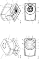
- Figures 1a and 1b show two oblique views of a preferred first embodiment of the storage container 1 for a storage and dispensing station for drugs.
- the storage container 1 according to the invention is part of the aforementioned storage and delivery station, the storage container usually being detachably arranged on a delivery station (not shown).
- components can be arranged in the storage container or the delivery station.
- Figure 1b can be seen, which shows the storage container from below, this does not include a motor in the embodiment shown, but only a coupling piece 31, via which a separating device (shown in more detail in the following figures) can be coupled to a motor in the delivery station.
- the storage container 1 comprises a housing 10 with a circular cylindrical section 11, to which a bottom section 12 adjoins at the bottom.
- the bottom section 12 is connected to the upper part of the housing via a handle 13 with which the storage container 1 can be taken from a corresponding dispensing station.
- a circular recess 22 is arranged around the coupling piece 31, which is described in more detail in the following figures.
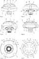
- FIGS. 2a and 2b show top views according to the first embodiment, wherein a lid 4 has been omitted in both figures in order to illustrate the interior of the storage container.
- a separating device 40 is arranged in a receiving space defined by the circular cylindrical section 11 of the housing. This comprises a central main section 48 and a plurality of projections 42 arranged on the main section 48. These projections 42 can be formed in one piece with the main section, but it is also possible for them to be detachable components can be fastened to the main section 48.
- a medicament channel 41 is formed between two projections 42, via which medicament portions arranged in the storage container one (in Figure 2a shown) delivery channel 21 can be supplied.
- the main section 48 of the separating device 40 comprises a conical surface 43 with four depressions 44 which are formed radially on the channels 41 and are intended to support the delivery of medicament portions to the medicament channels.
- the projections are not designed as sections of a circular hollow cylinder, but are withdrawn or flattened in the middle section (relative to the axis of rotation), i.e. in these areas there is a gap between the projections and the inner wall of the circular cylindrical section 11 of the housing (The exact configuration of the projections in relation to the circular cylindrical section is described in more detail below).
- the separating device shown in the top view is also omitted and the bottom surface 20 can be seen with a dispensing opening 21 and a circular recess 22. Via the dispensing opening, medicament portions arranged in the medicament channels 41 are dispensed when a dispensing channel is aligned with the dispensing opening.
- the circular recess 22 is provided for receiving medicament dust that arises when the medicament portions are separated.
- a circular opening is provided in which a coupling device 30 is arranged, via which the separating device can be coupled to a drive which, in the embodiment shown, is not arranged in the storage container.
- the coupling device itself can be designed in one piece with the separating device, but usually the separating device and the coupling device are detachably connected to one another, to enable the separation device to be exchanged quickly without a coupling device.
- Figures 3a and 3b show an oblique view and a side view of a section through the first embodiment of the storage container according to the invention, wherein, as in particular Figure 3a it can be seen that the cut is made in such a way that it cuts through the separating device 40 between the medicament channels 41.
- a gap is provided between an inner wall 3 of the circular cylindrical section 11 of the housing 10 and an outer jacket surface 461 of a central section 46 of a projection 42, through which medicament dust can trickle down onto the bottom surface 20 (the exact structure of the projections is referenced with reference to FIG described on the following figures).
- a slot is made in the area of the bottom opening 21 in the circular cylindrical section, through which a retaining section 51 of a retaining means 50 is introduced.
- the retaining section prevents, when a drug channel is aligned at the dispensing opening, drug portions arranged above the drug channel from being dispensed through the channel; only the drug portion contained in the channel upon alignment is indicated.
- Figures 4a and 4b also show two sectional views, the section being orthogonal to that of FIGS Figures 3a and 3b is led. Also based on the Figures 4a and 4b it can be seen that a gap is formed between the inner wall 3 of the circular cylindrical section 11 and a lateral surface 461 of the central section of a projection. Like it the Figures 3a and 3b As can also be seen from FIGS. 4a and 4b, the bottom surface 20 is designed sloping towards the center and comprises a recess 22 so that medicament dust trickling down through the gap can reach the recess 22 via the sloping bottom surface. Furthermore is the Figures 4a and 4b it can be seen that the lower surface 49 of the separating device is also formed at an angle, so that a gap is formed between the bottom surface 20 and the separating device, through which medicament dust can reach the recess 22.
- the separating device comprises four channels 41 which are defined by four projections 42.
- the main body 48 extends beyond the projections 42, ie in the area of the projections a circumferential depression is formed which supports the feeding of the medicament portions into the channels 41.
- the separating device 40 comprises a conical upper surface 43 with four depressions 44 which are aligned with the medicament channels. Aligned with the recesses 44 and the medicament channels 41, recesses 44a are formed in the main body 48, which interact with the Wells 44 support the delivery of medicament portions into the medicament channels 41.
- the projections 42 each comprise two end sections 45 with lateral surfaces 451 and central sections 46 with lateral surfaces 461
- Figures 5e and 5f it can already be seen that the projections are not circular arc-shaped in relation to the central axis of rotation, but that the central sections are reduced in this regard, ie the radius of the central sections is smaller than the radius of the end sections. This is explained in more detail with reference to the following figures.
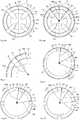
- Figures 6a and 6b show the arrangement of the separating device 40 in the circular cylindrical guide space with the inner wall 3 provided by the guide section 11.
- the separating device comprises four channels 41 and four projections 42 Figures 6a and 6b
- the projections in the area of the end sections 45 with lateral surfaces 451 rest on the wall of the guide section 11, whereas a lateral surface 461 of a central section 46 of a projection does not rest on the wall, but rather a gap is formed between the lateral surface and the wall. Via this gap, the medicament dust produced during the separation can pass the separation device onto the bottom surface of the storage container.
- the radius RMA that is to say the distance between the lateral surface and the central axis of rotation DA
- the radius RMI that is to say the distance between the lateral surface and the central axis of rotation DA
- FIG. 11 shows a plan view of a second embodiment of a separating device, which is designed essentially in accordance with the first embodiment, with the exception that only three medicament channels 41 are provided. The remaining versions correspond to the first embodiment.
- Figure 9 shows a third embodiment of the separating device, with both end sections of a projection protruding from the middle section in this embodiment as well, ie the radius RMA at the end sections 45 is greater than the radius RMI at the middle sections 46 central axis of rotation formed in the shape of a circular arc and rises gently in the transition area to the end sections.
- the middle section can also be formed in that it is not arcuate, but simply a straight line is formed between the end sections, which would lead to a gap with a different shape.
- Figure 10 shows a fourth embodiment of the separating device.
- this embodiment only one of the end sections of a projection protrudes with respect to the central section, ie the radius RMA is only greater than the radius RMI of the central section in one of the end sections.
- the “other” end section 47 is designed in exactly the same way as the central section, ie the lateral surface 471 is formed in the area corresponding to the lateral surface 461 of the central section.
- the separating device When separating drug portions, the separating device is regularly rotated clockwise according to the embodiment shown, ie the protruding end sections run "in front of" a drug channel towards the dispensing opening (the one in the embodiment shown below the right drug channel is arranged). When rotating counterclockwise, the projecting end sections 45 follow the drug channels. The edges of the projecting end sections 45 formed in the embodiment shown are suitable at the transition between the end section and the medicament channel to detach medicament dust adhering to the wall therefrom. With an appropriately designed separating device, it is therefore possible to detach at least part of the medicament dust adhering to the wall by briefly rotating counterclockwise and to feed it to the bottom surface and, if necessary, to a recess therein. In this way, excessive deposition of drug dust on the wall can be avoided, and a constant increase in the friction between the separating device and the wall is avoided.
- the design of the projections according to the invention also ensures in all four embodiments that the friction between the separating device and the wall is reduced due to the reduced contact surface wall / outer surface compared to storage containers according to the prior art.
Landscapes
- Engineering & Computer Science (AREA)
- Mechanical Engineering (AREA)
- Physics & Mathematics (AREA)
- General Physics & Mathematics (AREA)
- Health & Medical Sciences (AREA)
- Life Sciences & Earth Sciences (AREA)
- Animal Behavior & Ethology (AREA)
- General Health & Medical Sciences (AREA)
- Public Health (AREA)
- Veterinary Medicine (AREA)
- Pharmacology & Pharmacy (AREA)
- Medical Preparation Storing Or Oral Administration Devices (AREA)
- Basic Packing Technique (AREA)
Description
- Die vorliegende Erfindung betrifft einen Vorratsbehälter für eine Vorrats- und Abgabestation für Arzneimittel.
- Moderne Blisterautomaten, wie sie beispielsweise in der
WO 2013/034504 A1 offenbart sind, umfassen, je nach Ausbaustufe, mehrere hundert Vorrats- und Abgabestationen für Arzneimittel. In diesen sind jeweils eine Mehrzahl von Arzneimittelportionen einer bestimmten Arzneimittelart gelagert, und auf Anforderung können einzelne oder mehrere Arzneimittelportionen abgegeben werden. Mit den Blisterautomaten werden die in den Vorrats- und Abgabestationen gelagerten Arzneimittel patientenindividuell gemäß den ärztlich verordneten Einnahmezeitpunkten zusammengestellt und verblistert. - Zum Zusammenstellen der Arzneimittelportionen werden entsprechende Vorrats- und Abgabestationen zur Abgabe einer oder mehrerer vereinzelter Arzneimittelportionen angesteuert. Bei der Ansteuerung einer Vorrats- und Abgabestation wird mit einer Vereinzelungseinrichtung eine einzelne Arzneimittelportion separiert und über eine Abgabeöffnung einer Führungseinrichtung des Blisterautomaten übergeben. Mittels der Führungseinrichtung wird eine abgegebene Arzneimittelportion, ggf. unter Zwischenschaltung einer Sammeleinrichtung, einer Verpackungseinrichtung zugeführt, welche einzelne oder mehrere Arzneimittelportionen entsprechend den ärztlichen Vorgaben verblistert.
- Die zur Vereinzelung von Arzneimittelportionen verwendete Vereinzelungseinrichtung ist üblicherweise kreiszylinderförmig ausgebildet und ist in einem entsprechenden Führungsraum des Vorratsbehälters ausgebildet. An dem Umfang der Vereinzelungseinrichtung ist eine Mehrzahl von Arzneimittelkanälen vorgesehen, über welche Arzneimittelportionen der Abgabeöffnung in einer Bodenfläche des Vorratsbehälters zugeführt werden. Zwischen den einzelnen Arzneimittelkanälen sind Vorsprünge ausgebildet, die einstückig mit einem Hauptkörper der Vereinzelungseinrichtung ausgebildet sind oder lösbar an diesem befestigbar sind. Bei Vorratsbehältern gemäß dem Stand der Technik weisen die Vorsprünge regelmäßig eine kreisbogenförmige Mantelfläche auf, die an einer inneren Wandung des Führungsraums, in welchem die Vereinzelungseinrichtung angeordnet ist, anliegen (im Rahmen dieser Anmeldung sei mit dem Begriff des "Anliegens" nicht ausgedrückt, dass eine Fläche vollumfänglich eine andere berührt, sondern dass ggf. zumindest abschnittsweise ein kleiner (Ring-) Spalt ausgebildet ist). Legt man eine Umgebende um die äußeren Mantelflächen der Vorsprünge, ergibt sich ein Kreis, dessen Radius lediglich geringfügig geringer als der Radius des Aufnahmeraumes ist. Die Vereinzelungseinrichtungen weisen bei dem Stand der Technik (bei Vernachlässigung der Arzneimittelkanäle) also eine kreisförmige Grundfläche auf.
- In den Vorratsbehältern für die Vorrats- und Abgabestationen sind jeweils eine Vielzahl von Arzneimittelportionen angeordnet. Bei der Vereinzelung einer Arzneimittelportion wird die Vereinzelungseinrichtung um einen bestimmten Winkel rotiert, um eine in einem Arzneimittelkanal angeordnete Arzneimittelportion der Abgabeöffnung zuzuführen. In Abhängigkeit von der Form der Arzneimittelportionen und der Anzahl der in dem Vorratsbehälter angeordneten Arzneimittelportionen reiben diese bei der Vereinzelung sowohl aneinander als auch an den Bauteilen des Vorratsbehälters. Dadurch kommt es zu Abplatzungen bei den Arzneimittelportionen und es bildet sich eine Art Arzneimittelstaub. Dieser setzt sich an sämtlichen Bauteilen des Vorratsbehälters ab, unter anderem auch an der Wandung des Führungsabschnitts, in welchem die Vereinzelungseinrichtung angeordnet ist.
- Aufgrund der Ablagerung des Arzneimittelstaubes, insbesondere an der Wandung des Führungsabschnittes, erhöht sich die Reibung zwischen den Mantelflächen der Vorsprünge und der Wandung, so dass für eine Rotation der Vereinzelungseinrichtung bei zunehmender Arzneimittelstaubablagerung eine erhöhte Kraft aufzubringen ist. Durch die ungleichmäßige, zur Rotation der Vereinzelungseinrichtung aufzuwendende Kraft ist es schwierig, die Vereinzelungseinrichtung präzise zu steuern, so dass es zu Fehlabgaben kommen kann, was zu fehlerhaften Zusammenstellungen von Arzneimittelportionen führen kann.
- Es ist Aufgabe der vorliegenden Erfindung, einen Vorratsbehälter für Vorrats- und Abgabestationen bereitzustellen, bei dem solche fehlerhaften Abgaben vermieden werden.
- Die Aufgabe wird erfindungsgemäß gelöst durch einen Vorratsbehälter nach Patentanspruch 1. Der erfindungsgemäße Vorratsbehälter für eine Vorrats- und Abgabestation für Arzneimittelportionen umfasst ein einen Aufnahmeraum für Arzneimittelportionen umschließendes Gehäuse mit einem Führungsabschnitt und einer Bodenfläche, wobei eine innere Wandung des Führungsabschnitts einen kreiszylinderförmigen Führungsraum definiert und wobei die Bodenfläche eine Abgabeöffnung aufweist. Bei dem erfindungsgemäßen Vorratsbehälter ist in dem Führungsabschnitt des Gehäuses eine Vereinzelungseinrichtung mit einer zentralen Drehachse angeordnet. Die Vereinzelungseinrichtung umfasst einen zentralen Hauptabschnitt und eine Mehrzahl von Vorsprüngen, wobei jeder Vorsprung zwei Endabschnitte und einen Mittelabschnitt aufweist und wobei zwischen zwei Endabschnitten benachbarter Vorsprünge jeweils ein Arzneimittelkanal ausgebildet ist.
- Bezogen auf die Drehachse können die Vorsprünge flacher als der Hauptkörper der Führungseinrichtung ausgebildet sein, was die Zuführung der Arzneimittelportionen zu den Arzneimittelkanälen unterstützt. Gemäß dem Stand der Technik ist die äußere Mantelfläche regelmäßig kreisbogenförmig (bezogen auf eine zentrale Drehachse) ausgebildet und die Vorsprünge bilden daher (bei Vernachlässigung der Arzneimittelkanäle) eine Art Hohlzylinder, dessen äußere Mantelfläche an der inneren Wandung des Führungsabschnitts anliegt.
- Bei dem erfindungsgemäßen Vorratsbehälter sind die Vorsprünge anders ausgebildet. Es ist erfindungsgemäß vorgesehen, dass die Mittelabschnitte der Vorsprünge in Bezug auf zumindest einen der Endabschnitte zurückgenommen sind und der zumindest eine Endabschnitt jedes Vorsprungs derart ausgebildet ist, dass dessen Außenfläche an der Wandung des Führungsabschnitts anliegt (im Rahmen dieser Anmeldung sei mit dem Begriff des "Anliegens" nicht ausgedrückt, dass eine Fläche vollumfänglich eine andere berührt, sondern dass ggf. zumindest abschnittsweise ein eine Rotation der Vereinzelungseinrichtung ermöglichender schmaler bzw. kleiner (Ring-) Spalt ausgebildet ist) .
- Anders als bei bekannten Vorratsbehältern ist es also erfindungsgemäß vorgesehen, dass die Vorsprünge nur mit einem kleinen Abschnitt an der Wandung anliegen (oder geringfügig von dieser beabstandet sind) und ggf. von bzw. an dieser geführt sind, wobei es erfindungsgemäß vorgesehen ist, dass es sich bei diesem Abschnitt um einen Endabschnitt handelt, an welchen sich ein Arzneimittelkanal anschließt. Bei dem erfindungsgemäßen Vorratsbehälter liegt also nur ein geringer Teil der Mantelfläche der Vorsprünge an der Wandung des Führungsabschnitts an, nämlich die Summe der vorgenannten Endabschnitte. Wesentlich ist, dass die Mittelabschnitte der Vorsprünge gegenüber den Endabschnitten "zurückgenommen" sind, sich also radial gesehen nicht so weit zu der Wandung erstrecken wie zumindest einer der Endabschnitte jedes Vorsprungs. Bei den Mittelabschnitten ist also, im Vergleich zu den vorgenannten Endabschnitten, ein (breiterer) Spalt zwischen der Wandung und dem Mittelabschnitt vorgesehen.
- Wie dieser "Spalt" geometrisch genau ausgebildet ist, hängt von der Außenfläche des Mittelabschnitts ab. Im Rahmen dieser Erfindung ist mit dem Begriff des "Spalts" bei den Mittelabschnitten lediglich gemeint, dass der Abstand Wandung/Mantelfläche des Mittelabschnitts größer ist als der Abstand Wandung/Mantelfläche des Endabschnitts. Wenn die Mittelabschnitte bogenförmig ausgebildet sind, bedingt dies, dass der Spalt zwischen Wandung und Mittelabschnitt wie ein Segment eines Hohlzylinders ausgebildet ist. Alternativ kann der Mittelabschnitt in Bezug auf die Wandung auch wie eine Art Sekante ausgeführt sein, wodurch der Spalt dann eher die Form eines Kreissegmentes hätte.
- Eine entsprechende Ausgestaltung der Vorsprünge hat zur Folge, dass bei der Vereinzelung entstehender Arzneimittelstaub im Bereich der Mittelabschnitte durch den Spalt herabrieseln kann und so rasch zur Bodenfläche geführt wird, wo dieser bei entsprechender Ausbildung der Bodenfläche zu einer Aufnahmeöffnung in der Bodenfläche geführt werden kann.
- Dass der Arzneimittelstaub "ungehindert" durch den Spalt zwischen Wandung und Mittelabschnitt des Vorsprungs fallen kann, hat zur Folge, dass sich weniger Arzneimittelstaub an der Wandung absetzt und festsetzt. In der Summe bedingt die erfindungsgemäße Ausgestaltung der Vorsprünge eine verminderte Reibfläche Wandung/Vereinzelungseinrichtung, die aufzuwendende Kraft zur Drehung der Vereinzelungseinrichtung ist geringer. Wesentlich ist hier, dass sich die Kraft, die zur Drehung der Vereinzelungseinrichtung in dem Führungsabschnitt notwendig ist, auch bei vermehrter Arzneimittelstaubbildung nur geringfügig ändert, da sich weniger Arzneimittelstaub an der Wandung festsetzt. Da die zur Drehung aufzuwendende Kraft sich bei Staubbildung nur geringfügig ändert, ist die Vereinzelungseinrichtung präziser zu steuern bzw. zu drehen. Die Wahrscheinlichkeit von Fehlabgaben (beispielsweise durch mangelhafte Ausrichtung eines Arzneimittelkanals an der Abgabeöffnung) ist bei dem erfindungsgemäßen Vorratsbehälter vermindert.
- Die erfindungsgemäße Ausgestaltung der Vorsprünge hat einen weiteren erheblichen Vorteil. Zwar ist auch erfindungsgemäß nicht zu vermeiden, dass Arzneimittelstaub im Bereich der Arzneimittelkanäle herabfällt, jedoch ist der Anteil des in den Kanälen herabfallenden Arzneimittelstaubs bezogen auf die Gesamtmenge des Arzneimittelstaubes vermindert, so dass weniger Arzneimittelstaub zu der (und durch die) Abgabeöffnung in der Bodenfläche gelangt. Erfindungsgemäß wird damit der Eintrag von Arzneimittelstaub in den Blisterautomaten vermieden, was die Zeitintervalle zwischen Arzneimittelstaub-bedingten Reinigungen verlängert und somit die Stillstandzeit des Blisterautomaten verringert.
- Bedingt durch die Form der Vorsprünge weisen diese stets zwei Endabschnitte auf, wobei jeder dieser Endabschnitte an einen Arzneimittelkanal grenzt. Zumindest einer dieser Endabschnitte liegt an der Wandung des Führungsabschnitts an, hat also einen größeren "Radius" als der zurückgenommene Mittelabschnitt. Wie genau der zweite Endabschnitt ausgebildet ist, ist für das Funktionieren der Erfindung nicht wesentlich. Wesentlich ist vielmehr, dass an der Wandung anliegende Endabschnitte eine gleichmäßige und schlagfreie, reibungsarme Rotation der Vereinzelungseinrichtung in dem Führungsabschnitt erlauben, was regelmäßig bei drei entsprechenden Endabschnitten der Fall ist (ggf. auch bereits bei zwei Endabschnitten, wenn diese entsprechend breit sind).
- Wie oben dargelegt, kommt es auch bei dem erfindungsgemäßen Vorratsbehälter zu Ablagerungen von Arzneimittelstaub. Bei einer bevorzugten Ausführungsform ist es daher vorgesehen, dass die Endabschnitte, deren Außenflächen an der Wandung des Führungsabschnitts anliegen, bei sämtlichen Vorsprüngen einheitlich verteilt sind. Wenn pro Vorsprung nur ein solcher Endabschnitt vorgesehen ist, bedeutet dies, dass diese Endabschnitte (von der Drehachse aus betrachtet) stets rechts oder links an dem Vorsprung angeordnet sind. In Abhängigkeit von der Drehrichtung sind die an der Wandung anliegenden Endabschnitte (nachfolgend kurz "vorspringende" Endabschnitte; "vorspringend" in Bezug auf den Mittelabschnitt) dann "hinten" oder "vorne" an dem Vorsprung angeordnet. Im "normalen" Vereinzelungsbetrieb ist die Drehrichtung regelmäßig so gewählt, dass die vorspringenden Endabschnitte "hinten" liegen, d. h. ein Arzneimittelkanal einem Endabschnitt nachfolgt. Dreht man die Drehrichtung, liegen die Endabschnitte bei den Vorsprüngen "vorne", folgen also einem Arzneimittelkanal in Drehrichtung nach.
- Dies eröffnet die Möglichkeit, mit der erfindungsgemäßen Ausführungsform eine Reinigung der Wandung des Führungsabschnitts vorzunehmen, und zwar indem man die Vereinzelungseinrichtung kurzfristig derart dreht, dass die vorspringenden Endabschnitte "vorne" liegen. Bei entsprechender Ausbildung der Endabschnitte kann dann mit der vorderen Kante der Endabschnitte anhaftender Arzneimittelstaub von der Wandung entfernt werden. Dieser fällt dann durch die Kanäle auf die Bodenfläche.
- Bei einer alternativen bevorzugten Ausführungsform ist es vorgesehen, dass beide Endabschnitte eines Vorsprungs derart ausgebildet sind, dass sie an der Wandung des Führungsabschnitts anliegen. Eine entsprechende Ausbildung verbessert die Zuführung einer Arzneimittelportion in den Arzneimittelkanal. Zwar ist dann das oben beschriebene Reinigen nicht mehr möglich, eine reibungsarme Drehung der Vereinzelungseinrichtung und eine Verminderung des Eintrags von Arzneimittelstaub in die Arzneimittelkanäle ist aber weiter gewährleistet.
- Um eine besonders ruhige Drehung der Vereinzelungseinrichtung zu gewährleisten, ist es bei einer bevorzugten Ausführungsform vorgesehen, dass die an der Wandung des Führungsabschnitts anliegenden Endabschnitte der Vorsprünge, unabhängig davon ob ein oder beide Vorsprünge entsprechend ausgebildet sind, symmetrisch über die Vereinzelungseinrichtung verteilt sind. Sind drei Arzneimittelkanäle und damit drei Vorsprünge vorgesehen, bedeutet dies, dass die Arzneimittelkanäle bezogen auf die Drehachse jeweils um einen Mittelpunktswinkel von 120° versetzt sind.
- Um ein Anhaften von Arzneimittelstaub bei der Wandung des Mittelabschnitts der Vorsprünge zu vermeiden, ist es bei einer bevorzugten Ausführungsform vorgesehen, dass die Vorsprünge zumindest im Bereich des Mittelabschnitts bei einer der Wandung zugewandten Mantelfläche eine Antihaftbeschichtung aufweisen.
- Um zu vermeiden, dass Arzneimittelportionen auf dem Hauptkörper der Vereinzelungseinrichtung liegen bleiben und zur Unterstützung der Zuführung von Arzneimittelportionen in die Arzneimittelkanäle, ist es bei einer bevorzugten Ausführungsform vorgesehen, dass die Vereinzelungseinrichtung eine konische Oberfläche mit einer Mehrzahl von an den Arzneimittelkanälen ausgerichteten Vertiefungen aufweist.
- Zur weiteren Unterstützung der Zuführung ist es darüber hinaus bevorzugt, dass der Hauptabschnitt oberhalb der Arzneimittelkanäle Rücksprünge aufweist.
- Nachfolgend werden bevorzugte Ausführungsformen des erfindungsgemäßen Vorratsbehälters für Vorrats- und Abgabestationen unter Bezugnahme auf die beigefügte Zeichnung beschrieben, in welcher
-
Figuren 1a und 1b verschiedene Schrägansichten einer ersten bevorzugten Ausführungsform des erfindungsgemäßen Vorratsbehälters zeigen; -
Figuren 2a und 2b Draufsichten der ersten erfindungsgemäßen Ausführungsform zeigen; -
Figuren 3a und 3b zwei Schnittansichten der ersten Ausführungsform zeigen; -
Figuren 4a und 4b ebenfalls zwei Schnittansichten, orthogonal zu den in denFiguren 3a und 3b dargestellten Schnittansichten, zeigen; -
Figuren 5a - 5f verschiedene Ansichten einer Vereinzelungseinrichtung der ersten Ausführungsform der erfindungsgemäßen Vorratsbehälter zeigen; -
Figuren 6a und 6b Draufsichten auf die Vereinzelungseinrichtung der ersten Ausführungsform zeigen; -
Figur 7 eine Detailansicht der Vereinzelungseinrichtung zeigt; -
Figur 8 eine Draufsicht einer Vereinzelungseinrichtung einer zweiten Ausführungsform zeigt; -
Figur 9 eine Draufsicht einer Vereinzelungseinrichtung einer dritten Ausführungsform zeigt; und -
Figur 10 eine Draufsicht einer Vereinzelungseinrichtung einer vierten Ausführungsform zeigt. -
Figuren 1a und 1b zeigen zwei Schrägansichten einer bevorzugten ersten Ausführungsform des Vorratsbehälters 1 für eine Vorrats- und Abgabestation für Arzneimittel. Der erfindungsgemäße Vorratsbehälter 1 ist ein Teil der vorgenannten Vorrats- und Abgabestation, wobei der Vorratsbehälter üblicherweise lösbar auf einer (nicht dargestellten) Abgabestation angeordnet ist. In Abhängigkeit von der genauen Ausführung des erfindungsgemäßen Vorratsbehälters sowie der Abgabestation können Bauelemente in dem Vorratsbehälter oder der Abgabestation angeordnet sein. Wie es inFigur 1b zu erkennen ist, die den Vorratsbehälter von unten zeigt, umfasst dieser bei der gezeigten Ausführungsform keinen Motor, sondern lediglich ein Kopplungsstück 31, über welches eine (in den nachfolgenden Figuren detaillierter dargestellte) Vereinzelungseinrichtung mit einem Motor in der Abgabestation koppelbar ist. - Der Vorratsbehälter 1 gemäß der ersten Ausführungsform umfasst ein Gehäuse 10 mit einem kreiszylinderförmigen Abschnitt 11, an welchen sich nach unten ein Bodenabschnitt 12 anschließt. Der Bodenabschnitt 12 ist mit dem oberen Teil des Gehäuses über einen Griff 13 verbunden, mit welchem der Vorratsbehälter 1 von einer entsprechenden Abgabestation genommen werden kann. Wie dies in
Figur 1b angedeutet ist, ist um das Kopplungsstück 31 eine kreisförmige Vertiefung 22 angeordnet, die in den nachfolgenden Figuren detaillierter beschrieben wird. - Die
Figuren 2a und 2b zeigen Draufsichten gemäß der ersten Ausführungsform, wobei bei beiden Figuren ein Deckel 4 fortgelassen ist, um das Innere des Vorratsbehälters zu veranschaulichen. Wie dies inFigur 2a zu erkennen ist, ist in einem durch den kreiszylinderförmigen Abschnitt 11 des Gehäuses definierten Aufnahmeraum eine Vereinzelungseinrichtung 40 angeordnet. Diese umfasst einen zentralen Hauptabschnitt 48 sowie eine Mehrzahl von an dem Hauptabschnitt 48 angeordneten Vorsprüngen 42. Diese können einstückig mit dem Hauptabschnitt ausgebildet sein, jedoch ist es auch möglich, dass diese als lösbare Bauelemente an dem Hauptabschnitt 48 befestigbar sind. Zwischen zwei Vorsprüngen 42 ist jeweils ein Arzneimittelkanal 41 ausgebildet, über welchen in dem Vorratsbehälter angeordnete Arzneimittelportionen einem (inFigur 2a dargestellten) Abgabekanal 21 zuführbar sind. Der Hauptabschnitt 48 der Vereinzelungseinrichtung 40 umfasst eine konische Oberfläche 43 mit vier Vertiefungen 44, die radial an den Kanälen 41 ausgebildet sind und die Zuführung von Arzneimittelportionen zu den Arzneimittelkanälen unterstützen sollen. Wie es bereits beiFigur 2a zu erahnen ist, sind die Vorsprünge nicht als Abschnitte eines kreisförmigen Hohlzylinders ausgebildet, sondern sind im Mittelabschnitt (bezogen auf die Drehachse) zurückgenommen bzw. abgeflacht, d. h. in diesen Bereichen besteht ein Spalt zwischen den Vorsprüngen und der inneren Wandung des kreiszylinderförmigen Abschnitts 11 des Gehäuses (die genaue Ausgestaltung der Vorsprünge im Verhältnis zu dem kreiszylinderförmigen Abschnitt wird nachfolgend detaillierter beschrieben). - Bei der in
Figur 2b dargestellten Draufsicht ist die Vereinzelungseinrichtung ebenfalls fortgelassen und man erkennt die Bodenfläche 20 mit einer Abgabeöffnung 21 und einer kreisförmigen Vertiefung 22. Über die Abgabeöffnung werden in den Arzneimittelkanälen 41 angeordnete Arzneimittelportionen bei Ausrichtung eines Abgabekanals an der Abgabeöffnung abgegeben. Die kreisförmige Vertiefung 22 ist zur Aufnahme von bei der Vereinzelung von Arzneimittelportionen entstehendem Arzneimittelstaub vorgesehen. In der Mitte der Bodenfläche 20 ist eine kreisförmige Öffnung vorgesehen, in der eine Kopplungseinrichtung 30 angeordnet ist, über welche die Vereinzelungseinrichtung mit einem Antrieb, der bei der gezeigten Ausführungsform nicht in dem Vorratsbehälter angeordnet ist, gekoppelt werden kann. Die Kopplungseinrichtung selbst kann einstückig mit der Vereinzelungseinrichtung ausgeführt sein, üblicherweise sind die Vereinzelungseinrichtung und die Kopplungseinrichtung aber lösbar miteinander verbunden, um den raschen Austausch der Vereinzelungseinrichtung ohne Kopplungseinrichtung zu ermöglichen. -
Figuren 3a und 3b zeigen eine Schrägansicht und eine Seitenansicht eines Schnittes durch die erste Ausführungsform des erfindungsgemäßen Vorratsbehälters, wobei, wie dies insbesondereFigur 3a zu entnehmen ist, der Schnitt derart durchgeführt ist, dass dieser die Vereinzelungseinrichtung 40 zwischen den Arzneimittelkanälen 41 durchschneidet. Wie diesFiguren 3a und 3b zu entnehmen ist, ist zwischen einer inneren Wandung 3 des kreiszylinderförmigen Abschnittes 11 des Gehäuses 10 und einer äußeren Mantelfläche 461 eines Mittelabschnitts 46 eines Vorsprungs 42 ein Spalt vorgesehen, durch welchen Arzneimittelstaub auf die Bodenfläche 20 herabrieseln kann (der genaue Aufbau der Vorsprünge wird unter Bezugnahme auf nachfolgende Figuren beschrieben). - Bei den
Figuren 3a und 3b sowie sämtlichen nachfolgenden Figuren ist der Spalt zwischen der Wandung 3 und der äußeren Mantelfläche eines Mittelabschnitts eines Vorsprungs 42 zur Veranschaulichung der Erfindung übertrieben breit dargestellt. In der Realität wird ein solcher Spalt schmaler ausgeführt sein, wobei die genaue Dimensionierung insbesondere von der Form der zu vereinzelnden Arzneimittelportionen abhängig ist. Bei größeren Arzneimittelportionen, bei denen gegebenenfalls noch mit größeren Mengen Arzneimittelstaub gerechnet werden kann, kann der Spalt selbstverständlich breiter gehalten werden als bei sehr kleinen Arzneimittelportionen. Wesentlich ist, dass ein entsprechender Spalt vorgesehen ist, über welchen Arzneimittelstaub an der Vereinzelungseinrichtung vorbei auf die Bodenfläche gelangen kann. - Wie es bei
Figur 3a zu erkennen ist, ist im Bereich der Bodenöffnung 21 in den kreiszylinderförmigen Abschnitt ein Schlitz eingebracht, durch welchen ein Rückhalteabschnitt 51 eines Rückhaltemittels 50 eingeführt ist. Der Rückhalteabschnitt verhindert, dass bei Ausrichtung eines Arzneimittelkanals an der Abgabeöffnung über dem Arzneimittelkanal angeordnete Arzneimittelportionen durch den Kanal abgegeben werden; lediglich die bei Ausrichtung in dem Kanal enthaltene Arzneimittelportion wird angegeben. -
Figuren 4a und 4b zeigen ebenfalls zwei Schnittansichten, wobei der Schnitt orthogonal zu dem aus denFiguren 3a und 3b geführt ist. Auch anhand derFiguren 4a und 4b kann man erkennen, dass zwischen der inneren Wandung 3 des kreiszylinderförmigen Abschnittes 11 und einer Mantelfläche 461 des Mittelabschnitts eines Vorsprungs ein Spalt ausgebildet ist. Wie es denFiguren 3a und 3b sowie 4a und 4b ebenfalls zu entnehmen ist, ist die Bodenfläche 20 zur Mitte hin abfallend ausgebildet und umfasst eine Vertiefung 22, so dass über den Spalt herabrieselnder Arzneimittelstaub über die abfallende Bodenfläche in die Vertiefung 22 gelangen kann. Ferner ist denFiguren 4a und 4b zu entnehmen, dass die untere Fläche 49 der Vereinzelungseinrichtung ebenfalls schräg ausgebildet ist, so dass zwischen der Bodenfläche 20 und der Vereinzelungseinrichtung ein Spalt ausgebildet ist, über welchen Arzneimittelstaub zu der Vertiefung 22 gelangen kann. - Die
Figuren 5a - 5f zeigen verschiedene Ansichten der Vereinzelungseinrichtung der ersten Ausführungsform, wobei zusammen mit der Vereinzelungseinrichtung 40 das Kopplungsstück 31 der Kopplungseinrichtung dargestellt ist. Anhand derFiguren 5a - 5d wird zunächst der allgemeine Aufbau der Vereinzelungseinrichtung beschrieben, Details der erfindungsgemäßen Gestaltung der Vorsprünge werden mit Bezug auf nachfolgende Figuren beschrieben. Die Vereinzelungseinrichtung umfasst bei der ersten Ausführungsform vier Kanäle 41, die durch vier Vorsprünge 42 definiert sind. Der Hauptkörper 48 erstreckt sich über die Vorsprünge 42 hinaus, d. h. im Bereich der Vorsprünge ist eine umlaufende Vertiefung ausgebildet, die die Zuführung der Arzneimittelportionen in die Kanäle 41 unterstützt. Die Vereinzelungseinrichtung 40 umfasst eine konische obere Fläche 43 mit vier Vertiefungen 44, die an den Arzneimittelkanälen ausgerichtet sind. An den Vertiefungen 44 und den Arzneimittelkanälen 41 ausgerichtet sind Rücksprünge 44a in dem Hauptkörper 48 ausgebildet, die im Zusammenspiel mit den Vertiefungen 44 die Zuführung von Arzneimittelportionen in die Arzneimittelkanäle 41 unterstützen. - Wie es den
Figuren 5e und 5f zu entnehmen ist, umfassen die Vorsprünge 42 jeweils zwei Endabschnitte 45 mit Mantelflächen 451 und Mittelabschnitte 46 mit Mantelflächen 461. Bei denFiguren 5e und 5f ist bereits zu erkennen, dass die Vorsprünge in Bezug auf die zentrale Drehachse nicht kreisbogenförmig ausgebildet sind, sondern dass die Mittelabschnitte diesbezüglich zurückgenommen sind, d. h. der Radius bei den Mittelabschnitten geringer ist als der Radius bei den Endabschnitten. Dies ist in Bezug auf die nachfolgenden Figuren näher erläutert. -
Figuren 6a und 6b zeigen die Anordnung der Vereinzelungseinrichtung 40 in dem von dem Führungsabschnitt 11 bereitgestellten kreiszylinderförmigen Führungsraum mit der inneren Wandung 3. Bei der gezeigten ersten Ausführungsform umfasst die Vereinzelungseinrichtung vier Kanäle 41 sowie vier Vorsprünge 42. Wie es in denFiguren 6a und 6b zu erkennen ist, liegen die Vorsprünge im Bereich der Endabschnitte 45 mit Mantelflächen 451 an der Wandung des Führungsabschnittes 11 an, wohingegen eine Mantelfläche 461 eines Mittelabschnitts 46 eines Vorsprungs nicht an der Wandung anliegt, sondern ein Spalt zwischen der Mantelfläche und der Wandung ausgebildet ist. Über diesen Spalt kann der bei der Vereinzelung entstehende Arzneimittelstaub an der Vereinzelungseinrichtung vorbei auf die Bodenfläche des Vorratsbehälters gelangen. Wie es beiFigur 6b veranschaulicht ist, ist der Radius RMA (also der Abstand der Mantelfläche zu der zentralen Drehachse DA) bei den Endabschnitten 45 größer als der Radius RMI bei den Mittelabschnitten 46. - Im Detail dargestellt ist dies in
Figur 7 , wo deutlich zu erkennen ist, dass die Vorsprünge im Bereich der Endabschnitte 45 an der Wandung des Führungsabschnittes anliegen, dann zurückgehen und einen Spalt freilassen, durch welchen der Arzneimittelstaub zur Bodenfläche gelangen kann. -
Figur 8 zeigt eine Draufsicht auf eine zweite Ausführungsform einer Vereinzelungseinrichtung, welche im Wesentlichen entsprechend der ersten Ausführungsform ausgebildet ist, mit der Ausnahme, dass lediglich drei Arzneimittelkanäle 41 vorgesehen sind. Die restlichen Ausführungen entsprechen der ersten Ausführungsform. -
Figur 9 zeigt eine dritte Ausführungsform der Vereinzelungseinrichtung, wobei auch bei dieser Ausführungsform beide Endabschnitte eines Vorsprungs gegenüber dem Mittelabschnitt vorspringen, d. h. der Radius RMA bei den Endabschnitten 45 größer ist als der Radius RMI bei den Mittelabschnitten 46. Bei der gezeigten Ausführungsform ist der Mittelabschnitt bezogen auf die zentrale Drehachse kreisbogenförmig ausgebildet und steigt im Übergangsbereich zu den Endabschnitten sanft an. Bei alternativen Ausführungsformen kann der Mittelabschnitt auch dadurch gebildet werden, dass dieser nicht bogenförmig ausgebildet ist, sondern schlicht eine gerade Linie zwischen den Endabschnitten ausgebildet ist, was zu einem Spalt mit einer anderen Form führen würde. -
Figur 10 zeigt eine vierte Ausführungsform der Vereinzelungseinrichtung. Im Unterschied zu den vorgenannten Ausführungsformen ist bei dieser Ausführungsform lediglich einer der Endabschnitte eines Vorsprungs bezüglich des Mittelabschnittes vorspringend, d. h. nur bei einem der Endabschnitte ist der Radius RMA größer als der Radius RMI des Mittelabschnitts. Der "andere" Endabschnitt 47 ist bei der gezeigten Ausführungsform genauso ausgebildet wie der Mittelabschnitt, d. h. die Mantelfläche 471 ist in dem Bereich entsprechend der Mantelfläche 461 des Mittelabschnitts ausgebildet. - Bei der Vereinzelung von Arzneimittelportionen wird die Vereinzelungseinrichtung entsprechend der gezeigten Ausführungsform regelmäßig im Uhrzeigersinn gedreht, d. h. die vorspringenden Endabschnitte laufen "vor" einem Arzneimittelkanal auf die Abgabeöffnung zu (die bei der gezeigten Ausführungsform unter dem rechten Arzneimittelkanal angeordnet ist). Bei einer Drehbewegung gegen den Uhrzeigersinn laufen die vorspringenden Endabschnitte 45 den Arzneimittelkanälen nach. Die bei der dargestellten Ausführungsform ausgebildeten Kanten der vorspringenden Endabschnitte 45 sind bei dem Übergang Endabschnitt/Arzneimittelkanal geeignet, an der Wandung anhaftenden Arzneimittelstaub von dieser zu lösen. Mit einer entsprechend ausgebildeten Vereinzelungseinrichtung ist es daher möglich, durch kurzzeitige Drehbewegungen gegen den Uhrzeigersinn zumindest einen Teil des an der Wandung anhaftenden Arzneimittelstaubs von dieser zu lösen und der Bodenfläche und ggf. einer in dieser vorhandenen Vertiefung zuzuführen. Auf diese Weise kann eine übermäßige Ablagerung von Arzneimittelstaub auf der Wandung vermieden werden, ein stetes Ansteigen der Reibung zwischen Vereinzelungseinrichtung und Wandung wird vermieden.
- Durch die erfindungsgemäße Gestaltung der Vorsprünge wird bei allen vier Ausführungsformen ferner sichergestellt, dass die Reibung zwischen der Vereinzelungseinrichtung und der Wandung aufgrund der verkleinerten Kontaktfläche Wandung/Mantelfläche gegenüber Vorratsbehältern nach dem Stand der Technik vermindert ist.
Claims (7)
- Vorratsbehälter (1) für eine Vorrats- und Abgabestation für Arzneimittelportionen, aufweisend:ein einen Aufnahmeraum (2) für Arzneimittelportionen umschließendes Gehäuse (10) mit einem Führungsabschnitt (11) und einer Bodenfläche (14), wobei eine innere Wandung (3) des Führungsabschnitts (11) einen kreiszylinderförmigen Führungsraum definiert und wobei die Bodenfläche (14) eine Abgabeöffnung (15) aufweist,eine in dem Führungsabschnitt (11) des Gehäuses (10) angeordnete Vereinzelungseinrichtung (40) mit einer zentralen Drehachse (DA), wobei die Vereinzelungseinrichtung (40) einen Hauptabschnitt (48) und eine Mehrzahl von Vorsprüngen (42) aufweist, wobei jeder Vorsprung (42) zwei Endabschnitte (45) und einen Mittelabschnitt (46) aufweist und zwischen zwei Endabschnitten (45) benachbarter Vorsprünge jeweils ein Arzneimittelkanal (41) ausgebildet ist,dadurch gekennzeichnet, dass die Mittelabschnitte (46) der Vorsprünge (42) in Bezug auf zumindest einen der Endabschnitte (45) zurückgenommen sind und der zumindest eine Endabschnitt (45) jedes Vorsprungs (42) derart ausgebildet ist, dass dessen Mantelfläche (451) an der Wandung (3) des Führungsabschnitts (11) anliegt.
- Vorratsbehälter (1) für eine Vorrats- und Abgabestation für Arzneimittelportionen nach Anspruch 1, dadurch gekennzeichnet, dass die Endabschnitte (45), deren Mantelflächen (451) an der Wandung (3) des Führungsabschnitts (11) anliegen, bei sämtlichen Vorsprüngen (42) einheitlich verteilt sind.
- Vorratsbehälter (1) für eine Vorrats- und Abgabestation für Arzneimittelportionen nach Anspruch 1, dadurch gekennzeichnet, dass beide Endabschnitte (45) eines Vorsprungs (42) derart ausgebildet sind, dass sie an der Wandung (3) des Führungsabschnitts anliegen.
- Vorratsbehälter (1) für eine Vorrats- und Abgabestation für Arzneimittelportionen nach einem der Ansprüche 1 - 3, dadurch gekennzeichnet, dass die an der Wandung (3) des Führungsabschnitts (11) anliegenden Endabschnitte (45) der Vorsprünge (42) symmetrisch über die Vereinzelungseinrichtung (40) verteilt sind.
- Vorratsbehälter (1) für eine Vorrats- und Abgabestation für Arzneimittelportionen nach einem der Ansprüche 1 - 4, dadurch gekennzeichnet, dass die Vorsprünge (42) zumindest im Bereich des Mittelabschnitts (46) bei einer der Wandung (3) zugewandten Mantelfläche (461) eine Antihaftbeschichtung aufweisen.
- Vorratsbehälter (1) für eine Vorrats- und Abgabestation für Arzneimittelportionen nach einem der Ansprüche 1 - 5, dadurch gekennzeichnet, dass die Vereinzelungseinrichtung (40) eine konische Oberfläche (43) mit einer Mehrzahl von an den Arzneimittelkanälen (41) ausgerichteten Vertiefungen (44) aufweist.
- Vorratsbehälter (1) für eine Vorrats- und Abgabestation für Arzneimittelportionen nach einem der Ansprüche 1 - 6, dadurch gekennzeichnet, dass der Hauptabschnitt (48) oberhalb der Arzneimittelkanäle (41) Rücksprünge (44a) aufweist.
Priority Applications (5)
| Application Number | Priority Date | Filing Date | Title |
|---|---|---|---|
| EP18191874.9A EP3616675B1 (de) | 2018-08-31 | 2018-08-31 | Vorratsbehälter für eine vorrats- und abgabestation für arzneimittel |
| JP2021510868A JP7304938B2 (ja) | 2018-08-31 | 2019-05-24 | 製薬の貯蔵及び分配ステーション用貯蔵容器 |
| KR1020217005501A KR102694096B1 (ko) | 2018-08-31 | 2019-05-24 | 약품용 보관 및 분배 스테이션을 위한 보관 용기 |
| CN201980056289.XA CN112638346B (zh) | 2018-08-31 | 2019-05-24 | 用于药品份的储存及分配站的储存容器 |
| PCT/EP2019/063515 WO2020043334A1 (de) | 2018-08-31 | 2019-05-24 | Vorratsbehälter für eine vorrats- und abgabestation für arzneimittel |
Applications Claiming Priority (1)
| Application Number | Priority Date | Filing Date | Title |
|---|---|---|---|
| EP18191874.9A EP3616675B1 (de) | 2018-08-31 | 2018-08-31 | Vorratsbehälter für eine vorrats- und abgabestation für arzneimittel |
Publications (2)
| Publication Number | Publication Date |
|---|---|
| EP3616675A1 EP3616675A1 (de) | 2020-03-04 |
| EP3616675B1 true EP3616675B1 (de) | 2021-04-14 |
Family
ID=63452479
Family Applications (1)
| Application Number | Title | Priority Date | Filing Date |
|---|---|---|---|
| EP18191874.9A Active EP3616675B1 (de) | 2018-08-31 | 2018-08-31 | Vorratsbehälter für eine vorrats- und abgabestation für arzneimittel |
Country Status (5)
| Country | Link |
|---|---|
| EP (1) | EP3616675B1 (de) |
| JP (1) | JP7304938B2 (de) |
| KR (1) | KR102694096B1 (de) |
| CN (1) | CN112638346B (de) |
| WO (1) | WO2020043334A1 (de) |
Families Citing this family (1)
| Publication number | Priority date | Publication date | Assignee | Title |
|---|---|---|---|---|
| US11352194B2 (en) * | 2020-06-16 | 2022-06-07 | Becton Dickinson Rowa Germany Gmbh | Storage container for a storage and dispensing station |
Family Cites Families (18)
| Publication number | Priority date | Publication date | Assignee | Title |
|---|---|---|---|---|
| US2227167A (en) * | 1939-07-14 | 1940-12-31 | Morton Salt Co | Dispenser for tablets |
| US2572995A (en) * | 1946-03-26 | 1951-10-30 | Allen S Dunbar | Antenna |
| TW557277B (en) * | 2001-09-30 | 2003-10-11 | Yuyama Mfg Co Ltd | Medicine packing apparatus |
| US7516829B2 (en) * | 2002-04-25 | 2009-04-14 | Kite International Co., Ltd. | Vending machine of encapsulated article of commerce |
| GB0315509D0 (en) * | 2003-07-02 | 2003-08-06 | Meridica Ltd | Dispensing device |
| DE102006027521B4 (de) * | 2006-06-10 | 2016-01-07 | Edwin Kohl | Anlage zur personenbezogenen Bestückung von Medikamentenspendern |
| WO2011108448A1 (ja) * | 2010-03-01 | 2011-09-09 | 株式会社湯山製作所 | 薬剤払出機の粉除去装置 |
| US20130062363A1 (en) * | 2010-05-17 | 2013-03-14 | Yuyama Mfg. Co., Ltd. | Tablet Cassette |
| NL2007384C2 (nl) | 2011-09-09 | 2013-03-12 | Ppm Engineering B V | Systeem en werkwijze voor het verpakken van gedoseerde hoeveelheden vaste medicijnen. |
| DK2703299T3 (en) * | 2012-08-31 | 2016-06-06 | Carefusion Switzerland 317 Sarl | A storage and metering station for storing and dispensing metered amounts of solid drug servings |
| KR101449717B1 (ko) * | 2013-01-02 | 2014-10-15 | 주식회사 인포피아 | 약제 포장장치용 정제 카트리지 |
| WO2015052797A1 (ja) * | 2013-10-09 | 2015-04-16 | 株式会社タカゾノテクノロジー | 薬剤充填装置 |
| GB2531996B (en) * | 2014-10-20 | 2018-01-17 | Trig1 Ltd | Dispensing container with contents level indication |
| EP3199141A1 (de) * | 2016-01-29 | 2017-08-02 | Becton Dickinson Rowa Germany GmbH | Vorratsbehälter für eine vorrats- und abgabestation für arzneimittel |
| TWI724134B (zh) * | 2016-03-25 | 2021-04-11 | 日商湯山製作所有限公司 | 片劑盒用轉子以及片劑盒 |
| US10255524B2 (en) * | 2016-06-03 | 2019-04-09 | Becton Dickinson Rowa Germany Gmbh | Method for providing a singling device of a storage and dispensing container |
| EP3358538B1 (de) * | 2017-02-03 | 2022-03-30 | Becton Dickinson Rowa Germany GmbH | Vorrats- und abgabestation für einen blisterautomaten |
| US10380824B2 (en) * | 2017-02-03 | 2019-08-13 | Becton Dickinson Rowa Germany Gmbh | Storage and dispensing station for blister packaging machine |
-
2018
- 2018-08-31 EP EP18191874.9A patent/EP3616675B1/de active Active
-
2019
- 2019-05-24 WO PCT/EP2019/063515 patent/WO2020043334A1/de not_active Ceased
- 2019-05-24 KR KR1020217005501A patent/KR102694096B1/ko active Active
- 2019-05-24 CN CN201980056289.XA patent/CN112638346B/zh active Active
- 2019-05-24 JP JP2021510868A patent/JP7304938B2/ja active Active
Non-Patent Citations (1)
| Title |
|---|
| None * |
Also Published As
| Publication number | Publication date |
|---|---|
| KR20210049105A (ko) | 2021-05-04 |
| JP2022500103A (ja) | 2022-01-04 |
| KR102694096B1 (ko) | 2024-08-09 |
| WO2020043334A1 (de) | 2020-03-05 |
| EP3616675A1 (de) | 2020-03-04 |
| CN112638346B (zh) | 2024-05-28 |
| CN112638346A (zh) | 2021-04-09 |
| JP7304938B2 (ja) | 2023-07-07 |
Similar Documents
| Publication | Publication Date | Title |
|---|---|---|
| EP3925590B1 (de) | Vorratsbehälter für eine vorrats- und abgabestation | |
| EP4044136B1 (de) | Vorrats- und abgabestation für einen blisterautomaten | |
| EP3610468B1 (de) | Vorratsbehälter für eine vorrats- und abgabestation | |
| EP3407854A1 (de) | Vorratsbehälter für eine vorrats- und abgabestation für arzneimittel | |
| EP3421381B1 (de) | Zentriervorrichtung | |
| WO2021254738A1 (de) | Vorratsbehälter für eine vorrats- und abgabestation | |
| EP3616675B1 (de) | Vorratsbehälter für eine vorrats- und abgabestation für arzneimittel | |
| EP3156338B1 (de) | Vorratsbehälter für eine vorrats- und abgabestation für arzneimittel | |
| EP3463731B1 (de) | Schneidplatte für ein fräswerkzeug und fräswerkzeug | |
| EP3926594B1 (de) | Vorratsbehälter für eine vorrats- und abgabestation | |
| EP4524043B1 (de) | Vorratsbehälter für eine vorrats- und abgabestation und verfahren zum anpassen des vorratsbehälters | |
| EP3991712B1 (de) | Vorratsbehälter für eine vorrats- und abgabestation und vorrats- und abgabestation | |
| EP3617080A1 (de) | Ausrichtvorrichtung zum ausrichten von tabletten, verfahren zum ausrichten von tabletten | |
| EP4067245B1 (de) | Vorrats- und abgabestation für einen blisterautomaten | |
| EP4585525A1 (de) | Vorratsbehälter für eine vorrats- und abgabestation für einen blisterautomaten sowie verfahren zum anpassen des vorratsbehälters | |
| WO2018121963A1 (de) | Vorratsbehälter für eine vorrats- und abgabestation für arzneimittelportionen | |
| EP3879503A1 (de) | Vorrats- und abgabestation für arzneimittel | |
| EP3945504B1 (de) | Vorratsbehälter für eine vorrats- und abgabestation | |
| EP4631888A1 (de) | Vorratsvorrichtung für kleinstückgüter, kit zum lagerfähig-machen einer vorratsstation für kleinstückgüter und verfahren zum einlagern von vorratsstationen | |
| DE102007008047A1 (de) | Vorrichtung zum geordneten Zuführen von Produkten wie Tabletten, Kapseln, Oblongs oder dergleichen in die Näpfe einer Blisterfolie | |
| EP2672468B1 (de) | Vorrichtung zur Vereinzelung von Münzen mit einer Gegenlaufrolle und einer Bürstenpaaranordnung zur Vereinzelung nebeneinander liegender Münzen | |
| EP4434903A1 (de) | Vorratsbehälter für eine vorrats- und abgabestation für einen blisterautomaten und verfahren zum vereinzeln von kleinstückgütern | |
| WO2025099573A1 (de) | Zuführrohr für tabletten und dergleichen | |
| DE60023313T2 (de) | Verbesserung einer vorrichtung zum ausrichten von behältern | |
| DE29504836U1 (de) | Dosierverschluß |
Legal Events
| Date | Code | Title | Description |
|---|---|---|---|
| PUAI | Public reference made under article 153(3) epc to a published international application that has entered the european phase |
Free format text: ORIGINAL CODE: 0009012 |
|
| STAA | Information on the status of an ep patent application or granted ep patent |
Free format text: STATUS: THE APPLICATION HAS BEEN PUBLISHED |
|
| AK | Designated contracting states |
Kind code of ref document: A1 Designated state(s): AL AT BE BG CH CY CZ DE DK EE ES FI FR GB GR HR HU IE IS IT LI LT LU LV MC MK MT NL NO PL PT RO RS SE SI SK SM TR |
|
| AX | Request for extension of the european patent |
Extension state: BA ME |
|
| STAA | Information on the status of an ep patent application or granted ep patent |
Free format text: STATUS: REQUEST FOR EXAMINATION WAS MADE |
|
| 17P | Request for examination filed |
Effective date: 20200626 |
|
| RBV | Designated contracting states (corrected) |
Designated state(s): AL AT BE BG CH CY CZ DE DK EE ES FI FR GB GR HR HU IE IS IT LI LT LU LV MC MK MT NL NO PL PT RO RS SE SI SK SM TR |
|
| GRAP | Despatch of communication of intention to grant a patent |
Free format text: ORIGINAL CODE: EPIDOSNIGR1 |
|
| STAA | Information on the status of an ep patent application or granted ep patent |
Free format text: STATUS: GRANT OF PATENT IS INTENDED |
|
| INTG | Intention to grant announced |
Effective date: 20210114 |
|
| GRAS | Grant fee paid |
Free format text: ORIGINAL CODE: EPIDOSNIGR3 |
|
| GRAA | (expected) grant |
Free format text: ORIGINAL CODE: 0009210 |
|
| STAA | Information on the status of an ep patent application or granted ep patent |
Free format text: STATUS: THE PATENT HAS BEEN GRANTED |
|
| AK | Designated contracting states |
Kind code of ref document: B1 Designated state(s): AL AT BE BG CH CY CZ DE DK EE ES FI FR GB GR HR HU IE IS IT LI LT LU LV MC MK MT NL NO PL PT RO RS SE SI SK SM TR |
|
| REG | Reference to a national code |
Ref country code: GB Ref legal event code: FG4D Free format text: NOT ENGLISH |
|
| REG | Reference to a national code |
Ref country code: CH Ref legal event code: EP |
|
| REG | Reference to a national code |
Ref country code: DE Ref legal event code: R096 Ref document number: 502018004781 Country of ref document: DE |
|
| REG | Reference to a national code |
Ref country code: IE Ref legal event code: FG4D Free format text: LANGUAGE OF EP DOCUMENT: GERMAN |
|
| REG | Reference to a national code |
Ref country code: AT Ref legal event code: REF Ref document number: 1381646 Country of ref document: AT Kind code of ref document: T Effective date: 20210515 |
|
| REG | Reference to a national code |
Ref country code: NL Ref legal event code: FP |
|
| REG | Reference to a national code |
Ref country code: LT Ref legal event code: MG9D |
|
| PG25 | Lapsed in a contracting state [announced via postgrant information from national office to epo] |
Ref country code: LT Free format text: LAPSE BECAUSE OF FAILURE TO SUBMIT A TRANSLATION OF THE DESCRIPTION OR TO PAY THE FEE WITHIN THE PRESCRIBED TIME-LIMIT Effective date: 20210414 Ref country code: HR Free format text: LAPSE BECAUSE OF FAILURE TO SUBMIT A TRANSLATION OF THE DESCRIPTION OR TO PAY THE FEE WITHIN THE PRESCRIBED TIME-LIMIT Effective date: 20210414 Ref country code: FI Free format text: LAPSE BECAUSE OF FAILURE TO SUBMIT A TRANSLATION OF THE DESCRIPTION OR TO PAY THE FEE WITHIN THE PRESCRIBED TIME-LIMIT Effective date: 20210414 Ref country code: BG Free format text: LAPSE BECAUSE OF FAILURE TO SUBMIT A TRANSLATION OF THE DESCRIPTION OR TO PAY THE FEE WITHIN THE PRESCRIBED TIME-LIMIT Effective date: 20210714 |
|
| PG25 | Lapsed in a contracting state [announced via postgrant information from national office to epo] |
Ref country code: PL Free format text: LAPSE BECAUSE OF FAILURE TO SUBMIT A TRANSLATION OF THE DESCRIPTION OR TO PAY THE FEE WITHIN THE PRESCRIBED TIME-LIMIT Effective date: 20210414 Ref country code: LV Free format text: LAPSE BECAUSE OF FAILURE TO SUBMIT A TRANSLATION OF THE DESCRIPTION OR TO PAY THE FEE WITHIN THE PRESCRIBED TIME-LIMIT Effective date: 20210414 Ref country code: NO Free format text: LAPSE BECAUSE OF FAILURE TO SUBMIT A TRANSLATION OF THE DESCRIPTION OR TO PAY THE FEE WITHIN THE PRESCRIBED TIME-LIMIT Effective date: 20210714 Ref country code: PT Free format text: LAPSE BECAUSE OF FAILURE TO SUBMIT A TRANSLATION OF THE DESCRIPTION OR TO PAY THE FEE WITHIN THE PRESCRIBED TIME-LIMIT Effective date: 20210816 Ref country code: RS Free format text: LAPSE BECAUSE OF FAILURE TO SUBMIT A TRANSLATION OF THE DESCRIPTION OR TO PAY THE FEE WITHIN THE PRESCRIBED TIME-LIMIT Effective date: 20210414 Ref country code: SE Free format text: LAPSE BECAUSE OF FAILURE TO SUBMIT A TRANSLATION OF THE DESCRIPTION OR TO PAY THE FEE WITHIN THE PRESCRIBED TIME-LIMIT Effective date: 20210414 Ref country code: IS Free format text: LAPSE BECAUSE OF FAILURE TO SUBMIT A TRANSLATION OF THE DESCRIPTION OR TO PAY THE FEE WITHIN THE PRESCRIBED TIME-LIMIT Effective date: 20210814 Ref country code: GR Free format text: LAPSE BECAUSE OF FAILURE TO SUBMIT A TRANSLATION OF THE DESCRIPTION OR TO PAY THE FEE WITHIN THE PRESCRIBED TIME-LIMIT Effective date: 20210715 |
|
| REG | Reference to a national code |
Ref country code: DE Ref legal event code: R097 Ref document number: 502018004781 Country of ref document: DE |
|
| PG25 | Lapsed in a contracting state [announced via postgrant information from national office to epo] |
Ref country code: SM Free format text: LAPSE BECAUSE OF FAILURE TO SUBMIT A TRANSLATION OF THE DESCRIPTION OR TO PAY THE FEE WITHIN THE PRESCRIBED TIME-LIMIT Effective date: 20210414 Ref country code: SK Free format text: LAPSE BECAUSE OF FAILURE TO SUBMIT A TRANSLATION OF THE DESCRIPTION OR TO PAY THE FEE WITHIN THE PRESCRIBED TIME-LIMIT Effective date: 20210414 Ref country code: ES Free format text: LAPSE BECAUSE OF FAILURE TO SUBMIT A TRANSLATION OF THE DESCRIPTION OR TO PAY THE FEE WITHIN THE PRESCRIBED TIME-LIMIT Effective date: 20210414 Ref country code: EE Free format text: LAPSE BECAUSE OF FAILURE TO SUBMIT A TRANSLATION OF THE DESCRIPTION OR TO PAY THE FEE WITHIN THE PRESCRIBED TIME-LIMIT Effective date: 20210414 Ref country code: RO Free format text: LAPSE BECAUSE OF FAILURE TO SUBMIT A TRANSLATION OF THE DESCRIPTION OR TO PAY THE FEE WITHIN THE PRESCRIBED TIME-LIMIT Effective date: 20210414 Ref country code: CZ Free format text: LAPSE BECAUSE OF FAILURE TO SUBMIT A TRANSLATION OF THE DESCRIPTION OR TO PAY THE FEE WITHIN THE PRESCRIBED TIME-LIMIT Effective date: 20210414 Ref country code: DK Free format text: LAPSE BECAUSE OF FAILURE TO SUBMIT A TRANSLATION OF THE DESCRIPTION OR TO PAY THE FEE WITHIN THE PRESCRIBED TIME-LIMIT Effective date: 20210414 |
|
| PLBE | No opposition filed within time limit |
Free format text: ORIGINAL CODE: 0009261 |
|
| STAA | Information on the status of an ep patent application or granted ep patent |
Free format text: STATUS: NO OPPOSITION FILED WITHIN TIME LIMIT |
|
| 26N | No opposition filed |
Effective date: 20220117 |
|
| REG | Reference to a national code |
Ref country code: CH Ref legal event code: PL |
|
| PG25 | Lapsed in a contracting state [announced via postgrant information from national office to epo] |
Ref country code: MC Free format text: LAPSE BECAUSE OF FAILURE TO SUBMIT A TRANSLATION OF THE DESCRIPTION OR TO PAY THE FEE WITHIN THE PRESCRIBED TIME-LIMIT Effective date: 20210414 |
|
| REG | Reference to a national code |
Ref country code: BE Ref legal event code: MM Effective date: 20210831 |
|
| PG25 | Lapsed in a contracting state [announced via postgrant information from national office to epo] |
Ref country code: LI Free format text: LAPSE BECAUSE OF NON-PAYMENT OF DUE FEES Effective date: 20210831 Ref country code: CH Free format text: LAPSE BECAUSE OF NON-PAYMENT OF DUE FEES Effective date: 20210831 |
|
| PG25 | Lapsed in a contracting state [announced via postgrant information from national office to epo] |
Ref country code: IS Free format text: LAPSE BECAUSE OF FAILURE TO SUBMIT A TRANSLATION OF THE DESCRIPTION OR TO PAY THE FEE WITHIN THE PRESCRIBED TIME-LIMIT Effective date: 20210814 Ref country code: LU Free format text: LAPSE BECAUSE OF NON-PAYMENT OF DUE FEES Effective date: 20210831 Ref country code: AL Free format text: LAPSE BECAUSE OF FAILURE TO SUBMIT A TRANSLATION OF THE DESCRIPTION OR TO PAY THE FEE WITHIN THE PRESCRIBED TIME-LIMIT Effective date: 20210414 |
|
| PG25 | Lapsed in a contracting state [announced via postgrant information from national office to epo] |
Ref country code: IT Free format text: LAPSE BECAUSE OF FAILURE TO SUBMIT A TRANSLATION OF THE DESCRIPTION OR TO PAY THE FEE WITHIN THE PRESCRIBED TIME-LIMIT Effective date: 20210414 Ref country code: IE Free format text: LAPSE BECAUSE OF NON-PAYMENT OF DUE FEES Effective date: 20210831 Ref country code: BE Free format text: LAPSE BECAUSE OF NON-PAYMENT OF DUE FEES Effective date: 20210831 |
|
| PG25 | Lapsed in a contracting state [announced via postgrant information from national office to epo] |
Ref country code: CY Free format text: LAPSE BECAUSE OF FAILURE TO SUBMIT A TRANSLATION OF THE DESCRIPTION OR TO PAY THE FEE WITHIN THE PRESCRIBED TIME-LIMIT Effective date: 20210414 |
|
| PG25 | Lapsed in a contracting state [announced via postgrant information from national office to epo] |
Ref country code: HU Free format text: LAPSE BECAUSE OF FAILURE TO SUBMIT A TRANSLATION OF THE DESCRIPTION OR TO PAY THE FEE WITHIN THE PRESCRIBED TIME-LIMIT; INVALID AB INITIO Effective date: 20180831 |
|
| PG25 | Lapsed in a contracting state [announced via postgrant information from national office to epo] |
Ref country code: MK Free format text: LAPSE BECAUSE OF FAILURE TO SUBMIT A TRANSLATION OF THE DESCRIPTION OR TO PAY THE FEE WITHIN THE PRESCRIBED TIME-LIMIT Effective date: 20210414 |
|
| PG25 | Lapsed in a contracting state [announced via postgrant information from national office to epo] |
Ref country code: TR Free format text: LAPSE BECAUSE OF FAILURE TO SUBMIT A TRANSLATION OF THE DESCRIPTION OR TO PAY THE FEE WITHIN THE PRESCRIBED TIME-LIMIT Effective date: 20210414 |
|
| PG25 | Lapsed in a contracting state [announced via postgrant information from national office to epo] |
Ref country code: MT Free format text: LAPSE BECAUSE OF FAILURE TO SUBMIT A TRANSLATION OF THE DESCRIPTION OR TO PAY THE FEE WITHIN THE PRESCRIBED TIME-LIMIT Effective date: 20210414 |
|
| REG | Reference to a national code |
Ref country code: AT Ref legal event code: MM01 Ref document number: 1381646 Country of ref document: AT Kind code of ref document: T Effective date: 20230831 |
|
| PGFP | Annual fee paid to national office [announced via postgrant information from national office to epo] |
Ref country code: FR Payment date: 20240723 Year of fee payment: 7 |
|
| PG25 | Lapsed in a contracting state [announced via postgrant information from national office to epo] |
Ref country code: AT Free format text: LAPSE BECAUSE OF NON-PAYMENT OF DUE FEES Effective date: 20230831 |
|
| PG25 | Lapsed in a contracting state [announced via postgrant information from national office to epo] |
Ref country code: AT Free format text: LAPSE BECAUSE OF NON-PAYMENT OF DUE FEES Effective date: 20230831 |
|
| PGFP | Annual fee paid to national office [announced via postgrant information from national office to epo] |
Ref country code: NL Payment date: 20250723 Year of fee payment: 8 |
|
| PGFP | Annual fee paid to national office [announced via postgrant information from national office to epo] |
Ref country code: DE Payment date: 20250724 Year of fee payment: 8 |
|
| PGFP | Annual fee paid to national office [announced via postgrant information from national office to epo] |
Ref country code: GB Payment date: 20250725 Year of fee payment: 8 |
|
| PGFP | Annual fee paid to national office [announced via postgrant information from national office to epo] |
Ref country code: AT Payment date: 20260410 Year of fee payment: 5 |