WO2016114048A1 - 映像投射装置 - Google Patents
映像投射装置 Download PDFInfo
- Publication number
- WO2016114048A1 WO2016114048A1 PCT/JP2015/084820 JP2015084820W WO2016114048A1 WO 2016114048 A1 WO2016114048 A1 WO 2016114048A1 JP 2015084820 W JP2015084820 W JP 2015084820W WO 2016114048 A1 WO2016114048 A1 WO 2016114048A1
- Authority
- WO
- WIPO (PCT)
- Prior art keywords
- vehicle
- video
- image
- display
- road surface
- Prior art date
- Legal status (The legal status is an assumption and is not a legal conclusion. Google has not performed a legal analysis and makes no representation as to the accuracy of the status listed.)
- Ceased
Links
Images






Classifications
-
- B—PERFORMING OPERATIONS; TRANSPORTING
- B60—VEHICLES IN GENERAL
- B60Q—ARRANGEMENT OF SIGNALLING OR LIGHTING DEVICES, THE MOUNTING OR SUPPORTING THEREOF OR CIRCUITS THEREFOR, FOR VEHICLES IN GENERAL
- B60Q1/00—Arrangement of optical signalling or lighting devices, the mounting or supporting thereof or circuits therefor
- B60Q1/0017—Devices integrating an element dedicated to another function
-
- B—PERFORMING OPERATIONS; TRANSPORTING
- B60—VEHICLES IN GENERAL
- B60Q—ARRANGEMENT OF SIGNALLING OR LIGHTING DEVICES, THE MOUNTING OR SUPPORTING THEREOF OR CIRCUITS THEREFOR, FOR VEHICLES IN GENERAL
- B60Q1/00—Arrangement of optical signalling or lighting devices, the mounting or supporting thereof or circuits therefor
- B60Q1/02—Arrangement of optical signalling or lighting devices, the mounting or supporting thereof or circuits therefor the devices being primarily intended to illuminate the way ahead or to illuminate other areas of way or environments
- B60Q1/04—Arrangement of optical signalling or lighting devices, the mounting or supporting thereof or circuits therefor the devices being primarily intended to illuminate the way ahead or to illuminate other areas of way or environments the devices being headlights
-
- B—PERFORMING OPERATIONS; TRANSPORTING
- B60—VEHICLES IN GENERAL
- B60Q—ARRANGEMENT OF SIGNALLING OR LIGHTING DEVICES, THE MOUNTING OR SUPPORTING THEREOF OR CIRCUITS THEREFOR, FOR VEHICLES IN GENERAL
- B60Q1/00—Arrangement of optical signalling or lighting devices, the mounting or supporting thereof or circuits therefor
- B60Q1/26—Arrangement of optical signalling or lighting devices, the mounting or supporting thereof or circuits therefor the devices being primarily intended to indicate the vehicle, or parts thereof, or to give signals, to other traffic
- B60Q1/34—Arrangement of optical signalling or lighting devices, the mounting or supporting thereof or circuits therefor the devices being primarily intended to indicate the vehicle, or parts thereof, or to give signals, to other traffic for indicating change of drive direction
-
- B—PERFORMING OPERATIONS; TRANSPORTING
- B60—VEHICLES IN GENERAL
- B60Q—ARRANGEMENT OF SIGNALLING OR LIGHTING DEVICES, THE MOUNTING OR SUPPORTING THEREOF OR CIRCUITS THEREFOR, FOR VEHICLES IN GENERAL
- B60Q1/00—Arrangement of optical signalling or lighting devices, the mounting or supporting thereof or circuits therefor
- B60Q1/26—Arrangement of optical signalling or lighting devices, the mounting or supporting thereof or circuits therefor the devices being primarily intended to indicate the vehicle, or parts thereof, or to give signals, to other traffic
- B60Q1/34—Arrangement of optical signalling or lighting devices, the mounting or supporting thereof or circuits therefor the devices being primarily intended to indicate the vehicle, or parts thereof, or to give signals, to other traffic for indicating change of drive direction
- B60Q1/38—Arrangement of optical signalling or lighting devices, the mounting or supporting thereof or circuits therefor the devices being primarily intended to indicate the vehicle, or parts thereof, or to give signals, to other traffic for indicating change of drive direction using immovably-mounted light sources, e.g. fixed flashing lamps
-
- B—PERFORMING OPERATIONS; TRANSPORTING
- B60—VEHICLES IN GENERAL
- B60Q—ARRANGEMENT OF SIGNALLING OR LIGHTING DEVICES, THE MOUNTING OR SUPPORTING THEREOF OR CIRCUITS THEREFOR, FOR VEHICLES IN GENERAL
- B60Q1/00—Arrangement of optical signalling or lighting devices, the mounting or supporting thereof or circuits therefor
- B60Q1/26—Arrangement of optical signalling or lighting devices, the mounting or supporting thereof or circuits therefor the devices being primarily intended to indicate the vehicle, or parts thereof, or to give signals, to other traffic
- B60Q1/34—Arrangement of optical signalling or lighting devices, the mounting or supporting thereof or circuits therefor the devices being primarily intended to indicate the vehicle, or parts thereof, or to give signals, to other traffic for indicating change of drive direction
- B60Q1/38—Arrangement of optical signalling or lighting devices, the mounting or supporting thereof or circuits therefor the devices being primarily intended to indicate the vehicle, or parts thereof, or to give signals, to other traffic for indicating change of drive direction using immovably-mounted light sources, e.g. fixed flashing lamps
- B60Q1/381—Arrangement of optical signalling or lighting devices, the mounting or supporting thereof or circuits therefor the devices being primarily intended to indicate the vehicle, or parts thereof, or to give signals, to other traffic for indicating change of drive direction using immovably-mounted light sources, e.g. fixed flashing lamps with several light sources activated in sequence, e.g. to create a sweep effect
-
- B—PERFORMING OPERATIONS; TRANSPORTING
- B60—VEHICLES IN GENERAL
- B60Q—ARRANGEMENT OF SIGNALLING OR LIGHTING DEVICES, THE MOUNTING OR SUPPORTING THEREOF OR CIRCUITS THEREFOR, FOR VEHICLES IN GENERAL
- B60Q1/00—Arrangement of optical signalling or lighting devices, the mounting or supporting thereof or circuits therefor
- B60Q1/26—Arrangement of optical signalling or lighting devices, the mounting or supporting thereof or circuits therefor the devices being primarily intended to indicate the vehicle, or parts thereof, or to give signals, to other traffic
- B60Q1/50—Arrangement of optical signalling or lighting devices, the mounting or supporting thereof or circuits therefor the devices being primarily intended to indicate the vehicle, or parts thereof, or to give signals, to other traffic for indicating other intentions or conditions, e.g. request for waiting or overtaking
-
- G—PHYSICS
- G01—MEASURING; TESTING
- G01C—MEASURING DISTANCES, LEVELS OR BEARINGS; SURVEYING; NAVIGATION; GYROSCOPIC INSTRUMENTS; PHOTOGRAMMETRY OR VIDEOGRAMMETRY
- G01C21/00—Navigation; Navigational instruments not provided for in groups G01C1/00 - G01C19/00
- G01C21/26—Navigation; Navigational instruments not provided for in groups G01C1/00 - G01C19/00 specially adapted for navigation in a road network
- G01C21/34—Route searching; Route guidance
- G01C21/36—Input/output arrangements for on-board computers
- G01C21/3626—Details of the output of route guidance instructions
- G01C21/365—Guidance using head up displays or projectors, e.g. virtual vehicles or arrows projected on the windscreen or on the road itself
-
- G—PHYSICS
- G02—OPTICS
- G02F—OPTICAL DEVICES OR ARRANGEMENTS FOR THE CONTROL OF LIGHT BY MODIFICATION OF THE OPTICAL PROPERTIES OF THE MEDIA OF THE ELEMENTS INVOLVED THEREIN; NON-LINEAR OPTICS; FREQUENCY-CHANGING OF LIGHT; OPTICAL LOGIC ELEMENTS; OPTICAL ANALOGUE/DIGITAL CONVERTERS
- G02F1/00—Devices or arrangements for the control of the intensity, colour, phase, polarisation or direction of light arriving from an independent light source, e.g. switching, gating or modulating; Non-linear optics
- G02F1/01—Devices or arrangements for the control of the intensity, colour, phase, polarisation or direction of light arriving from an independent light source, e.g. switching, gating or modulating; Non-linear optics for the control of the intensity, phase, polarisation or colour
- G02F1/13—Devices or arrangements for the control of the intensity, colour, phase, polarisation or direction of light arriving from an independent light source, e.g. switching, gating or modulating; Non-linear optics for the control of the intensity, phase, polarisation or colour based on liquid crystals, e.g. single liquid crystal display cells
- G02F1/133—Constructional arrangements; Operation of liquid crystal cells; Circuit arrangements
- G02F1/1333—Constructional arrangements; Manufacturing methods
- G02F1/1335—Structural association of cells with optical devices, e.g. polarisers or reflectors
- G02F1/1336—Illuminating devices
-
- G—PHYSICS
- G03—PHOTOGRAPHY; CINEMATOGRAPHY; ANALOGOUS TECHNIQUES USING WAVES OTHER THAN OPTICAL WAVES; ELECTROGRAPHY; HOLOGRAPHY
- G03B—APPARATUS OR ARRANGEMENTS FOR TAKING PHOTOGRAPHS OR FOR PROJECTING OR VIEWING THEM; APPARATUS OR ARRANGEMENTS EMPLOYING ANALOGOUS TECHNIQUES USING WAVES OTHER THAN OPTICAL WAVES; ACCESSORIES THEREFOR
- G03B17/00—Details of cameras or camera bodies; Accessories therefor
- G03B17/48—Details of cameras or camera bodies; Accessories therefor adapted for combination with other photographic or optical apparatus
- G03B17/54—Details of cameras or camera bodies; Accessories therefor adapted for combination with other photographic or optical apparatus with projector
-
- G—PHYSICS
- G03—PHOTOGRAPHY; CINEMATOGRAPHY; ANALOGOUS TECHNIQUES USING WAVES OTHER THAN OPTICAL WAVES; ELECTROGRAPHY; HOLOGRAPHY
- G03B—APPARATUS OR ARRANGEMENTS FOR TAKING PHOTOGRAPHS OR FOR PROJECTING OR VIEWING THEM; APPARATUS OR ARRANGEMENTS EMPLOYING ANALOGOUS TECHNIQUES USING WAVES OTHER THAN OPTICAL WAVES; ACCESSORIES THEREFOR
- G03B21/00—Projectors or projection-type viewers; Accessories therefor
- G03B21/12—Projectors or projection-type viewers; Accessories therefor adapted for projection of either still pictures or motion pictures
-
- G—PHYSICS
- G03—PHOTOGRAPHY; CINEMATOGRAPHY; ANALOGOUS TECHNIQUES USING WAVES OTHER THAN OPTICAL WAVES; ELECTROGRAPHY; HOLOGRAPHY
- G03B—APPARATUS OR ARRANGEMENTS FOR TAKING PHOTOGRAPHS OR FOR PROJECTING OR VIEWING THEM; APPARATUS OR ARRANGEMENTS EMPLOYING ANALOGOUS TECHNIQUES USING WAVES OTHER THAN OPTICAL WAVES; ACCESSORIES THEREFOR
- G03B21/00—Projectors or projection-type viewers; Accessories therefor
- G03B21/14—Details
-
- G—PHYSICS
- G03—PHOTOGRAPHY; CINEMATOGRAPHY; ANALOGOUS TECHNIQUES USING WAVES OTHER THAN OPTICAL WAVES; ELECTROGRAPHY; HOLOGRAPHY
- G03B—APPARATUS OR ARRANGEMENTS FOR TAKING PHOTOGRAPHS OR FOR PROJECTING OR VIEWING THEM; APPARATUS OR ARRANGEMENTS EMPLOYING ANALOGOUS TECHNIQUES USING WAVES OTHER THAN OPTICAL WAVES; ACCESSORIES THEREFOR
- G03B21/00—Projectors or projection-type viewers; Accessories therefor
- G03B21/54—Accessories
- G03B21/56—Projection screens
- G03B21/562—Screens moving during projection
-
- G—PHYSICS
- G08—SIGNALLING
- G08G—TRAFFIC CONTROL SYSTEMS
- G08G1/00—Traffic control systems for road vehicles
- G08G1/16—Anti-collision systems
- G08G1/166—Anti-collision systems for active traffic, e.g. moving vehicles, pedestrians, bikes
-
- G—PHYSICS
- G08—SIGNALLING
- G08G—TRAFFIC CONTROL SYSTEMS
- G08G1/00—Traffic control systems for road vehicles
- G08G1/16—Anti-collision systems
- G08G1/167—Driving aids for lane monitoring, lane changing, e.g. blind spot detection
-
- H—ELECTRICITY
- H04—ELECTRIC COMMUNICATION TECHNIQUE
- H04N—PICTORIAL COMMUNICATION, e.g. TELEVISION
- H04N9/00—Details of colour television systems
- H04N9/12—Picture reproducers
- H04N9/31—Projection devices for colour picture display, e.g. using electronic spatial light modulators [ESLM]
- H04N9/3179—Video signal processing therefor
-
- H—ELECTRICITY
- H04—ELECTRIC COMMUNICATION TECHNIQUE
- H04N—PICTORIAL COMMUNICATION, e.g. TELEVISION
- H04N9/00—Details of colour television systems
- H04N9/12—Picture reproducers
- H04N9/31—Projection devices for colour picture display, e.g. using electronic spatial light modulators [ESLM]
- H04N9/3191—Testing thereof
- H04N9/3194—Testing thereof including sensor feedback
-
- B—PERFORMING OPERATIONS; TRANSPORTING
- B60—VEHICLES IN GENERAL
- B60Q—ARRANGEMENT OF SIGNALLING OR LIGHTING DEVICES, THE MOUNTING OR SUPPORTING THEREOF OR CIRCUITS THEREFOR, FOR VEHICLES IN GENERAL
- B60Q1/00—Arrangement of optical signalling or lighting devices, the mounting or supporting thereof or circuits therefor
- B60Q1/02—Arrangement of optical signalling or lighting devices, the mounting or supporting thereof or circuits therefor the devices being primarily intended to illuminate the way ahead or to illuminate other areas of way or environments
- B60Q1/24—Arrangement of optical signalling or lighting devices, the mounting or supporting thereof or circuits therefor the devices being primarily intended to illuminate the way ahead or to illuminate other areas of way or environments for lighting other areas than only the way ahead
-
- B—PERFORMING OPERATIONS; TRANSPORTING
- B60—VEHICLES IN GENERAL
- B60Q—ARRANGEMENT OF SIGNALLING OR LIGHTING DEVICES, THE MOUNTING OR SUPPORTING THEREOF OR CIRCUITS THEREFOR, FOR VEHICLES IN GENERAL
- B60Q2400/00—Special features or arrangements of exterior signal lamps for vehicles
- B60Q2400/50—Projected symbol or information, e.g. onto the road or car body
-
- B—PERFORMING OPERATIONS; TRANSPORTING
- B60—VEHICLES IN GENERAL
- B60Q—ARRANGEMENT OF SIGNALLING OR LIGHTING DEVICES, THE MOUNTING OR SUPPORTING THEREOF OR CIRCUITS THEREFOR, FOR VEHICLES IN GENERAL
- B60Q9/00—Arrangement or adaptation of signal devices not provided for in one of main groups B60Q1/00 - B60Q7/00, e.g. haptic signalling
-
- G—PHYSICS
- G02—OPTICS
- G02F—OPTICAL DEVICES OR ARRANGEMENTS FOR THE CONTROL OF LIGHT BY MODIFICATION OF THE OPTICAL PROPERTIES OF THE MEDIA OF THE ELEMENTS INVOLVED THEREIN; NON-LINEAR OPTICS; FREQUENCY-CHANGING OF LIGHT; OPTICAL LOGIC ELEMENTS; OPTICAL ANALOGUE/DIGITAL CONVERTERS
- G02F1/00—Devices or arrangements for the control of the intensity, colour, phase, polarisation or direction of light arriving from an independent light source, e.g. switching, gating or modulating; Non-linear optics
- G02F1/01—Devices or arrangements for the control of the intensity, colour, phase, polarisation or direction of light arriving from an independent light source, e.g. switching, gating or modulating; Non-linear optics for the control of the intensity, phase, polarisation or colour
- G02F1/13—Devices or arrangements for the control of the intensity, colour, phase, polarisation or direction of light arriving from an independent light source, e.g. switching, gating or modulating; Non-linear optics for the control of the intensity, phase, polarisation or colour based on liquid crystals, e.g. single liquid crystal display cells
- G02F1/133—Constructional arrangements; Operation of liquid crystal cells; Circuit arrangements
- G02F1/1333—Constructional arrangements; Manufacturing methods
- G02F1/1335—Structural association of cells with optical devices, e.g. polarisers or reflectors
- G02F1/1336—Illuminating devices
- G02F1/133626—Illuminating devices providing two modes of illumination, e.g. day-night
- G02F1/133627—Projection-direct viewing
Definitions
- the present invention relates to a video projection apparatus.
- Video projectors typified by projectors have already been used in a wide range of fields as devices for enlarging and projecting a desired video, and more recently, as display devices for personal computers and mobile phones. It has been widely used.
- Patent Document 1 discloses a projection display device that uses a headlight as an external light source by disposing an LCD projector having excellent portability without incorporating a light source in front of a vehicle headlight as an external light source. Is disclosed.
- Patent Document 2 in order to solve the problem, the first state in which the projector is previously incorporated in the vehicle in front of the headlight and the projector or the headlight are moved, and the light beam from the headlight is directly moved.
- An embodiment in which the second state of irradiating the outside of the vehicle is realized and an image is displayed on the road is also shown.
- Patent Document 3 as a driving support device for a vehicle, it is attached to a headlight portion in front of the vehicle on a road ahead of the vehicle in order to effectively alert a passenger of the own vehicle when determining lane departure. It is known to display information for prompting an arousal by an irradiation means (laser).
- laser irradiation means
- Patent Document 4 a projector as a projection unit is attached to the head portion of a vehicle, and a route guidance image that guides in a branch direction based on route information searched by a navigation system is accompanied by setting a projection angle. And what is projected on the road surface ahead of a vehicle is already known.
- Patent Document 5 by projecting a drawing pattern composed of a target mark and a tracking line onto a road surface in front of the vehicle based on the traveling state of the own vehicle, the traveling destination of the own vehicle can be recognized. Therefore, a vehicle driving support device that enables appropriate driving is already known.
- the present invention has been achieved in view of the above-described problems in the prior art.
- the information is obtained on the road surface based on information on the vehicle such as the traveling state of the own vehicle (a moving body represented by an automobile or the like).
- the present application includes a plurality of means for solving the above problems.
- the present application is a video projection device that projects video, an acquisition unit that acquires information about a vehicle, and information acquired by the acquisition unit And a video projection unit that projects video based on the above.
- a video projection device that makes it possible to project and display information on a road surface or the like based on information on the vehicle.
- FIG. 1 is a perspective view from the front of a vehicle equipped with a video projection device according to an embodiment of the present invention and projecting a video on a road surface or the like. It is a perspective view from the back of the vehicle which mounts the video projection device concerning one embodiment of the present invention, and projects a video on the road surface etc. It is a figure which shows the whole structure of light distribution control ECU which comprises the said video projection apparatus. It is a block diagram which shows the further detailed structural example of the said light distribution control ECU and its peripheral element. It is a figure which shows an example of a structure of the video projection apparatus which concerns on one embodiment of this invention. It is a light ray figure also including the image surface of the said projector.
- FIGS. 1A and 1B a passenger car 10 is shown as an example of a host vehicle equipped with a video projection apparatus according to an embodiment of the present invention.
- a pair of left and right headlights 11 are provided in front of the main body of the passenger car 10.
- a lamp as a light emitter is incorporated in the pair of headlights 11.
- the passenger car 10 is mounted with a pair of left and right video projection devices described below.
- the image light from the said image projection apparatus is projected ahead of the own vehicle through a transparent window part, for example.
- the image projected on the road surface shows the current or subsequent direction of travel for pedestrians walking in the vicinity of the host vehicle, thereby ensuring higher safety. To do.
- FIG. 1B shows an example in which only one video projector is mounted at the front end of the vehicle body.
- the video light from the video projector is provided at the front end of the vehicle body, for example.
- the light is projected forward of the host vehicle through the transparent window portion 12 formed.
- FIGS. 2A and 2B show the rear of the passenger car 10 equipped with the video projection apparatus according to the embodiment of the present invention.
- Red tail lamps 13 and 13 ' are provided behind the rear.
- lamps that are light emitters are incorporated in the tail lamps 13 and 13 '.
- a pair of video projection devices are mounted on the left and right, and the video light from the video projection device is projected to the back of the host vehicle through a transparent window, for example. .
- FIG. 2B shows an example in which the video projection device is mounted, for example, near the roof of the vehicle body.
- the image light is projected to the rear of the host vehicle through a transparent window provided at the rear end of the vehicle body, as in FIG. 1B.
- the present invention is not limited to these examples. You may mount in places other than front and back (for example, a side mirror part, a roof top, the side surface of a vehicle body, a bottom face, etc.).
- the video projection device may be integrated into the headlight or tail lamp. That is, in the present invention, it is only necessary that a desired video can be projected onto the road surface or the like by the video projection device. Note that when the video projection apparatus is integrated into the headlight or tail lamp, the light source of the headlight or tail lamp can also be used as a light source for projection.
- FIG. 3 shows an example of the configuration of the electronic control unit (light distribution control ECU) mounted in the passenger car 10 described above.
- the light distribution control ECU 40 includes a CPU (central processing unit) 41, a RAM 42 and ROM 43 as storage means, and an input / output device (I / O unit) 44. Information from the following various information acquisition units and communication units is input to the light distribution control ECU via the I / O unit 44 to drive the headlight 11 and the video of the video projection device 500. Projection is controlled.
- the information from the various information acquisition units includes, for example, a speed signal indicating the traveling speed of the host vehicle, a signal indicating the engine state (ON / OFF), gear information indicating the gear position, and surrounding information.
- a hazard signal that informs the driver of the presence of danger, a steering wheel steering angle signal that indicates the steering angle of the steering wheel, a turn signal signal that indicates whether there is a turn signal (or "winker"), and whether the left or right lights / flashes, and Includes lamp lighting information indicating lighting / flashing states of the various lamps.
- information from the various information acquisition units for example, information (illuminance signal, chromaticity signal, etc.) from an external light sensor that detects light outside the car, video from a camera attached to the car Information, signals from distance sensors that detect distances between vehicles and other objects traveling in the vicinity, such as in front of the host vehicle, and signals from infrared sensors that detect conditions outside the vehicle at night Etc. are included.
- the information from the communication unit includes, for example, a so-called navigation which is information from a navigation device that performs GPS (Global Positioning System) signal, route guidance, etc., for determining the position of the host vehicle.
- Information includes information on vehicle-to-vehicle communication performed between other vehicles and road-to-vehicle communication performed between roads and vehicles.
- FIG. 4 shows a more detailed configuration of the above-described light distribution control ECU 40 and its peripheral elements. That is, in FIG. 4, a direction indicator sensor 51, a steering wheel angle sensor 52, a shift position sensor 53, a vehicle speed sensor 54, an accelerator operation sensor 55, a brake operation sensor 56, an illuminance sensor 57, a chromaticity sensor 58, and an engine start sensor 59 , And a signal from the hazard lamp sensor 60 are input to the light distribution control ECU 40. Further, a signal from the camera 61 is input to the ECU 40 through the image processing unit 62, and signals from the GPS receiving unit 63 and the map information output unit 64 are input to the ECU 40 through the calculation unit 65.
- the projector 100 constituting the video projection apparatus receives a control signal from the light distribution control ECU 40 and a signal from the projection signal output unit 110 (video signal projected onto a road surface or the like) via the control unit 120.
- the projection of the video onto the road surface or the like described below is executed.
- the light distribution control ECU 40 further receives signals from the headlight sensor 66 and the high / low sensor 67.
- Projection optical system 501 is an optical system that projects an image onto a road surface or the like, and includes a lens and / or a mirror.
- the display element 502 is an element that modulates transmitted light or reflected light to generate an image.
- a transmissive liquid crystal panel, a reflective liquid crystal panel, a DMD (Digital Micromirror Device: registered trademark) panel, or the like is used.
- the display element driver 503 sends a drive signal to the display element 502 to cause the display element 502 to generate an image.
- the light source 505 generates light for image projection, and uses a high-pressure mercury lamp, a xenon lamp, an LED light source, a laser light source, or the like.
- the power source 506 supplies power to the light source 505.
- the power source 506 supplies necessary power to each of the other units.
- the illumination optical system 504 collects the light generated by the light source 505, makes it uniform, and irradiates the display element 502 with it.
- the cooling unit 515 cools each part such as the light source 505, the power source 506, or the display element 502 that is in a high temperature state by an air cooling method or a liquid cooling method as necessary.
- the operation input unit 507 is an operation button or a light receiving unit of a remote controller, and inputs an operation signal from the user.
- the video signal input unit 531 connects an external video output device and inputs video data.
- the audio signal input unit 533 connects an external audio output device and inputs audio data.
- the audio output unit 540 can perform audio output based on the audio data input to the audio signal input unit 533.
- the voice output unit 540 may output a built-in operation sound or an error warning sound.
- the communication unit 532 is connected to an external information processing apparatus and inputs / outputs various control signals.
- Nonvolatile memory 508 stores various data used in the projector function.
- the data stored in the non-volatile memory 508 includes image data and video data prepared in advance for projection onto the road.
- the memory 509 stores video data to be projected, control parameters of each part of the apparatus, and the like.
- Control unit 510 controls the operation of each connected unit.
- the image adjustment unit 560 performs image processing on the video data input by the video signal input unit 531, the image data stored in the nonvolatile memory 508, and the video data.
- Examples of the image processing include scaling processing for enlarging, reducing, and deforming the image, bright adjustment processing for changing the brightness, contrast adjustment processing for changing the contrast curve of the image, and components obtained by decomposing the image into light components. Retinex processing for changing the weighting for each.
- the storage unit 570 records video, images, audio, various data, and the like.
- video, image, audio, various data, etc. may be recorded in advance at the time of product shipment, and video, image, audio, various data, etc. acquired from an external device, an external server, etc. via the communication unit 532 are recorded. It may be recorded.
- Video, images, various data, and the like recorded in the storage unit 570 may be output as projection video via the display element 502 and the projection optical system 501.
- the sound recorded in the storage unit 570 may be output from the sound output unit 540 as sound.
- the video projection device 500 can be equipped with various functions.
- the video projection apparatus 500 does not necessarily have all of the above-described configurations. Any configuration may be used as long as it has a function of projecting an image.
- FIG. 6 is a ray diagram of the projector including the image plane.
- image light emitted from a light source composed of an LED (not shown) and transmitted through an image display element passes through a filter and the like, is refracted by various lens systems, and further has a reflection effect according to the configuration. After receiving, it is projected onto the image plane 8 (road surface or the like).
- one image projection apparatus 500 and its projection optical system have been described.
- one or a plurality of (a pair of) projectors are mounted on a vehicle (or a headlight, It may be incorporated integrally with the tail lamp) to project a desired image onto the road surface or the like.
- the same video is projected from each video projection device onto a road surface or the like.
- the same image is displayed on the display element 502 in FIG. 5), or different images may be projected from the left and right image projection apparatuses and synthesized on the road surface (in that case, in FIG. 5).
- the display element 502 displays a video obtained by dividing a desired video into left and right).
- a configuration using a transmissive liquid crystal image display element as an image projection device for projecting an image on a road surface or the like has been described.
- the present invention is not limited to this, and the image projection device is not limited thereto.
- a reflection type image projection device including a micromirror such as a DLP (Digital Light Processing) device, and image light from a planar light-emitting diode capable of light modulation can be projected via a projection optical system.
- various video projection devices such as a video projection device. That is, in the present invention, it is only necessary that the video projection apparatus can project a desired video on a road surface or the like.
- the video projection apparatus described in detail above is mounted on the front and / or rear of the vehicle body as described above as an example, and thus various video images projected on the road surface or the like according to the relationship with the vehicle information. Specific examples will be described in detail below with reference to FIGS.
- FIG. 7 shows a form in which an arrow is projected onto the road surface in front of the vehicle when the turn signal is turned on / flashed when the vehicle 10 is driven by turning right / left.
- the video projection device projects an arrow 200, which is a video indicating the traveling direction of the host vehicle, on the road surface in front of the vehicle (FIG. 7A).
- the video projection device further projects an arrow 200 projected onto the road surface ahead of the vehicle based on the traveling speed of the host vehicle input from the vehicle speed sensor 54 and the steering angle of the steering wheel input from the steering wheel steering angle sensor 52. Is blinked (FIG. 7B).
- the turn signal may be interlocked (synchronized or alternately) with blinking of the turn signal, or the cycle of blinking the arrow 200 is made variable, and the blinking cycle is changed according to the input traveling speed or the steering wheel. It is also possible to set according to the steering angle.
- the projected image on the road surface or the like not only the traveling direction of the own vehicle but also the driving information of the own vehicle (in this case, the vehicle speed and the steering angle of the steering wheel) with respect to drivers and pedestrians of other vehicles existing around.
- the driving information of the own vehicle in this case, the vehicle speed and the steering angle of the steering wheel
- a display method based on this in this case, blinking and blinking cycle
- a pair of video projection devices are incorporated as in the example of FIGS. 1A and 2A
- the projected images are combined to display a large video, thereby further safety.
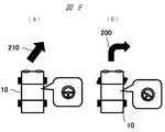
- the curved state of the arrow may be changed according to the driver's handle operation. That is, for example, before the driver actually operates the steering wheel, the arrow indicating the traveling direction of the vehicle is a straight arrow 210 (FIG. 8A), and when the steering wheel is actually operated, the arrow is changed to the steering angle.
- the corresponding curved arrow 200 FIG. 8B
- the display content is replaced with the above arrow, and, for example, a mark 230 (see FIG. 15A below) for notifying danger or an approach locus 220 made of a curve (see FIG. 12B below). It is also possible to change the display position (for example, at a position separated according to the traveling speed or at a position moved in the steering direction).
- the arrow 200 having the same color as the turn signal is turned on / flashing, or the display position of the mark (arrow 200) is changed (turning on the left or right side). It is also possible. Further, the presence / absence of blinker lighting / flashing can be detected, and in conjunction with the handle, when the winker is lighting / flashing, a right / left turn display by the arrow 200 can be performed.
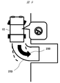
- FIG. 9 shows an example of a display when the steering wheel is operated when entering the garage, and an arrow 200 indicating the traveling direction is displayed behind the host vehicle 10 and a rectangle for displaying the traveling range of the host vehicle 10.
- a frame 220 is displayed.
- only the arrow 200 or only the rectangular frame 220 may be displayed, and further, a mark 230 (see FIG. 15A below) for notifying the danger instead of the arrow depending on the steering angle. May be displayed.
- the projected image on the road surface or the like particularly when entering the garage, it is possible to more reliably present (warn) to surrounding drivers and pedestrians to ensure high safety.
- the mark (arrow 200) is linked according to the distance from the own vehicle to the intersection in conjunction with GPS or navigation.
- An example of changing the distance to the display position is shown.
- the mark (arrow 200) is displayed far away, and the display position approaches the own vehicle 10 as approaching the intersection, that is, from the own vehicle to the intersection.
- the display position is set according to the distance up to.
- the color and shape of the mark (arrow 200) can be changed according to the distance to the intersection.
- the size of the mark (arrow 200) (more specifically, for “L” -shaped right / left turn depending on the distance to the intersection)
- the arrow 200) can be gradually increased, or the color of the mark (arrow 200) can be changed from blue to yellow to red.
- the mark (arrow 200) can be displayed / flashed large.
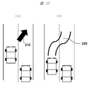
- the mark (straight arrow) 210 is placed on the road surface of the adjacent lane.
- an approach locus made up of a plurality of parallel (in this example, two) straight lines or curved lines that are obliquely displayed to display the locus. 220 may be displayed.
- the driver of the following vehicle traveling in the adjacent lane can be more surely recognized (warning) of the traveling direction of the host vehicle, thereby ensuring high safety. Make it possible.
- the above-mentioned projection display may not be in time or the projection time may be too short because the blinker lighting / flashing time is shorter than when turning right or left.
- the blinker instruction operation is mistaken, if the blinker is not lit / flashed for a predetermined time or longer, the projection display may not be performed.
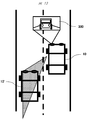
- a side region (a region indicated by a hatched portion on the left side of the vehicle in the figure) that is a blind spot of the driver is photographed by the camera 61.
- the ECU 40 of the host vehicle 10 replaces the mark such as the arrow described above and the other vehicle 10 traveling behind the host vehicle.
- the image 300 of ' is projected on the road surface ahead of the traveling direction.
- the driver who is driving is not likely to notice normally and can recognize (notice) the other vehicle 10 ′ traveling behind the vehicle, so it is particularly safe when changing lanes. It is possible to contribute to safe driving.
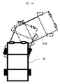
- the vehicle image 310 is projected onto the road surface or the like in the direction in which the vehicle is about to start. In this way, it is possible to more reliably present (warning) to surrounding drivers and pedestrians to ensure high safety.
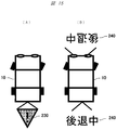
- a mark 230 that notifies the danger is projected on the road surface behind the vehicle (FIG. 15A).
- a character 240 “reversing” may be projected onto the road surface before and after the vehicle (FIG. 15B). According to such video projection, it is possible to more reliably present (warn) to surrounding drivers and pedestrians, particularly during parking, and to ensure high safety.
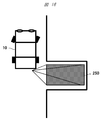
- a mark 250 (for example, a rectangular red surface) may be projected and displayed.
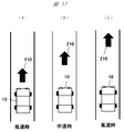
- the driver's gazing point changes depending on the traveling speed, and therefore, a straight arrow 210 is projected onto a projection distance set according to the traveling speed of the host vehicle 10.
- the projection is performed at a short distance (FIG. 17A) at a low speed, at a middle distance at a medium speed (FIG. 17B), and at a long distance at a high speed (FIG. 17C).
- the viewing angle range is low. Becomes a wide angle (shaded portion 260 in FIG. 18A), and accordingly, a wide angle display is performed, and the range of the viewing angle becomes a narrow angle (shaded portion 270 in FIG. 18B) at high speed. , It may be set to display in accordance with this.
- the display content when traveling in a tunnel, the display content may be different from that when traveling on an expressway or a general road.
- the display content in this example, the color of the straight arrow 210) is changed (color change) in synchronization with a sudden change in the brightness of ambient light or lighting of the small light.
- the mark (arrow 210) is irradiating intensively with a color that is difficult to see in the tunnel.
- the light distribution control ECU 40 described above may appropriately set the color of the straight arrow 210 that is the display content. Good.
- the mode can be switched (specifically, the light is switched on) by detecting a change in external light or illumination light in the tunnel.
- the signal from the vehicle speed sensor 54 is also used to detect the average travel speed for a certain period of time while taking the average travel speed into account. It is also possible to project the display content optimal for the driving information.
- the fact that the vehicle is traveling on a highway is recognized from the average traveling speed for a predetermined time.
- the display method during tunnel traveling may be the same as the display state in the evening / night time, for example.
- the present invention is not limited to the above-described embodiments and includes various modifications.
- the above-described embodiments are described in detail for the entire system in order to explain the present invention in an easy-to-understand manner, and are not necessarily limited to those having all the configurations described.
- a part of the configuration of one embodiment can be replaced with the configuration of another embodiment, and the configuration of another embodiment can be added to the configuration of one embodiment.
- each of the above-described configurations, functions, processing units, processing means, and the like may be realized by hardware by designing a part or all of them with, for example, an integrated circuit.
- Each of the above-described configurations, functions, and the like may be realized by software by interpreting and executing a program that realizes each function by the processor.
- Information such as programs, tables, and files that realize each function can be stored in a memory, a hard disk, a recording device such as an SSD (Solid State Drive), or a recording medium such as an IC card, an SD card, or a DVD.
- the flashing cycle is made variable according to the speed / steering angle.
- the display content / display position is variable according to the rudder angle (for example, it is an oblique mark when the blinker is activated and changes to an L-shaped mark when the rudder angle increases).
- the traveling range is displayed / arrow is changed according to the steering angle / gear.
- the projected image is linked (synchronized or alternated) with the turn signal lighting / flashing.
- the turn signal is lit / flashed for right / left turns, the turn signal is lit / flashed in the same color as the turn signal.
- the turn signal is lit / flashed when turning right / left, change the mark display position when turning right / left.
- the steering wheel is moved in a right turn / left turn, the presence / absence of blinker lighting / flashing is detected, and when the blinker lights / flashes, a right / left turn is displayed (that is, interlocking with the blinker and / or steering wheel) .
- the display distance of the mark is changed according to the distance to the intersection in conjunction with GPS or navigation (for example, if the distance to the intersection is far Display far away from the vehicle, and bring the display closer to your vehicle as the intersection gets closer).
- the blinker is turned on / flashed in the right / left turn, the color or shape of the mark is changed according to the distance to the intersection (for example, blue ⁇ yellow ⁇ red, or the size is gradually increased).
- a right turn / left turn arrow for example, L-shape
- the blinker When the blinker is turned on / flashed by changing the lane, the straight arrow is displayed diagonally without changing the arrow into an L-shaped image that makes a right / left turn image. (12) When the blinker is turned on / flashed by changing the lane, the mark is displayed in front of the left and right sides so that it can be seen by the following vehicle. (13) When the blinker is turned on / flashed by changing the lane, the location of the host vehicle is clarified by displaying the trajectory of the vehicle instead of the arrow. (14) When the blinker is turned on / flashed when the lane is changed, an image of the camera of the lane to be changed is displayed (for example, an image of a side surface that becomes a blind spot of the driver).
- the blinker lighting / flashing time is shorter than that when turning right or left, so the projection display may not be in time or the projection time may be too short. It is necessary to reduce the time difference by simplifying the processing method up to and to continue the projection display for a predetermined time or longer. (16) Assuming that the instruction operation of the winker is wrong, for example, the projection display is not performed unless the winker is lit / flashed after a predetermined time.
- the display contents are changed between when traveling on a tunnel or highway and when on a general road.
- the projection distance of the mark is changed according to the speed.
- the display contents are changed when traveling on a tunnel or expressway and when traveling on a general road. Since the viewing angle of the driver changes according to the running speed, it is displayed at a wide angle at low speed and at a narrow angle at high speed.
- the display content is changed when traveling on a tunnel or expressway and when traveling on a general road. In the tunnel, the display content is changed in sync with the lighting of the small light (color change).
- the driver when the driver does not turn on the light, the driver recognizes that the vehicle is traveling through the tunnel by detecting a change in external light or lighting in the tunnel. Recognizing that the vehicle is traveling on a highway from the average traveling speed over a certain period of time.
- the display method during tunnel traveling may be the same as the display state in the evening / nighttime, for example.
- the vehicle returns to the general road mode when there is a traffic jam. (25)
- a color that is difficult to see with tunnel illumination is consciously and intensely emitted. Or irradiate a color that is easily visible.
- the timing of turning off the light source is changed between the display mode from the video source input and the display mode such as running (for example, in the display mode such as running, the video projection device is switched on / off according to the driving situation, In the display mode from the source input, the video projector is always ON). In the display mode from the video source input, the headlight is turned off and the video projection device is turned on. In the display mode such as when traveling, both the headlight and the image projection device are turned on. (27) Turn on the light source of the video projector when necessary, and turn it off otherwise. (28) The light source can be turned on even when the engine is off. Alternatively, the image projection device is not activated when the engine is off. (29) The function is restricted when the engine is OFF (for example, security and warning are turned ON, and others (for example, display from video source input) are not performed). (30) When the engine is OFF, the power of the light source is set to the energy saving mode.
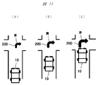
- the video indicating the direction of travel of the vehicle including an arrow or the like is displayed. Project onto the road surface ahead (intersection). In that case, for the purpose of calling attention of others who are watching the projected image (for example, pedestrians, other drivers, etc.), an arrow indicating the direction in which the vehicle travels is displayed. It is effective to display.
- the projected image moves simultaneously with the start of the vehicle, i.e., when both the vehicle and the projected image move, the other person watching the projected image is rather confused, There are cases where the original purpose cannot be achieved. Therefore, in this other embodiment, the static / moving of the projection position on the road surface of the projected image is appropriately switched according to the behavior of the host vehicle.
- FIG. 20 shows a state where the host vehicle 10 is stopped at an intersection.
- an image showing the direction in which the host vehicle travels is projected on the road surface in front of the host vehicle.
- the traveling direction of the host vehicle is set for the purpose of further urging the pedestrian and the driver of the opposite vehicle to pay attention to the traveling direction of the host vehicle.
- the arrow 200 shown (turned right in this example) is displayed and displayed as a moving image (for example, the arrow 200 blinks) for the purpose of improving visibility from a distance or a blind spot.
- the arrow 200 by this moving image is drawn with colored light (for example, red) that can be easily identified on the road surface.
- FIG. 21 shows a situation when the host vehicle 10 starts at the intersection and enters and passes through the intersection.
- the position of the arrow 200 projected on the road surface in front of the host vehicle remains stationary at the initial display position. That is, in this case, as is clear from FIGS. 20A to 20C, both the vehicles 10 move along the arrow 200 projected on the road surface, as if the host vehicle 10
- the arrow 200 is displayed as if the user steps on the top. 20 and 21, pedestrians, opposing vehicles, and pedestrian crossings are omitted for the sake of simplicity.
- the light distribution control ECU 40 includes, for example, a steering wheel steering angle sensor 52, a vehicle speed sensor 54, and an accelerator operation sensor 55. And the like, the behavior of the host vehicle 10 is grasped based on these signals, and the current position of the host vehicle 10 is calculated. On the other hand, for the arrow 200 projected on the road surface ahead of the host vehicle, it is possible to perform a calculation for correcting so that the position is displayed so as to remain stationary. Then, by changing and projecting the image generated on the display element 502 shown in FIG. 5 via the display element driving unit 503, the arrow 200 remains stationary. A display in which the vehicle 10 moves can be realized.
- the display position of the arrow 200 is not linked to the movement of the host vehicle 10 and the display position is
- the position of the vehicle 10 is linked with the movement of the vehicle by grasping the position of the host vehicle 10 based on the vehicle speed pulse, the steering angle of the steering wheel, etc. so as not to fluctuate as much as possible. (Ie, the display position on the road can be fixed / moved).
- the immobilization trigger may be a case where the host vehicle 10 has changed from a stopped state to a traveling state, a case where the steering wheel has started to be turned (when a predetermined rudder angle is detected), or a combination thereof. .
- the display position of the video is linked to the movement of the vehicle.
- the light distribution control ECU 40 grasps the behavior of the host vehicle 10 based on signals from various sensors and the like, and determines whether the display position is fixed / moved on the road.
- the static / motion of the image projected on the road surface is switched in accordance with the behavior of the host vehicle. More specifically, the projected image is moved when the host vehicle is stopped (indicated by the arrow 200). (Video) alerts others (pedestrians, opponent drivers, etc.) On the other hand, when the vehicle is moving (running), avoid dispersal of attention by moving the attention to the vehicle by stopping the projected image (fixing the projection position on the road surface) The safety can be improved.
- the display of the moving direction of the own vehicle when the own vehicle is about to turn right or left at the intersection has been described in detail. It is also possible to implement.
- the display can be similarly applied to the display when the steering wheel is operated when entering the garage.
- an arrow 200 indicating the traveling direction is displayed behind the host vehicle 10 and a rectangular frame 220 for displaying the traveling range of the host vehicle 10 is displayed.
- a moving image it is possible to more reliably present (warn) to surrounding drivers and pedestrians and to ensure higher safety. Even at that time, even if the host vehicle moves rearward, the display position including the arrow 200 projected on the rear road surface remains stationary at the initial position (immobilization).
- FIG. 15 when the host vehicle 10 moves backward or in the case of hazard-linked warning, a mark 230 (FIG. 15 (A) )), Or the character 240 (FIG. 15B) “reversing” projected onto the road surface in front of and behind the vehicle, etc., by displaying these as a moving image to the surrounding drivers and pedestrians. It becomes possible to call attention more reliably.
- FIG. 15A when the vehicle starts, it is not necessary to display the mark 230 for notifying the danger, and the display is not performed.
- the display of the character 240 may be moved together with the movement of the vehicle in reverse, or instead, As in the above embodiment, the display position may be fixed. According to such video display, it is possible to more reliably present (warn) to surrounding drivers and pedestrians, particularly during parking, and to ensure high safety. That is, in the above embodiment, the description has been mainly made by using the arrow as the display indicating the traveling direction of the vehicle. Also good.
- Projector 110 ... Projection signal output unit, 120 ... Control unit , 500 ... Video projection apparatus, 501 ... Projection optical system, 502 ... Display element, 503 ... Display element driver, 504 ... Illumination light System, 505 ... light source, 531 ... video signal input unit, 533 ... audio signal input unit, 532 ... communication unit.
Landscapes
- Engineering & Computer Science (AREA)
- Physics & Mathematics (AREA)
- General Physics & Mathematics (AREA)
- Mechanical Engineering (AREA)
- Radar, Positioning & Navigation (AREA)
- Remote Sensing (AREA)
- Signal Processing (AREA)
- Automation & Control Theory (AREA)
- Multimedia (AREA)
- Nonlinear Science (AREA)
- Chemical & Material Sciences (AREA)
- Crystallography & Structural Chemistry (AREA)
- Mathematical Physics (AREA)
- Optics & Photonics (AREA)
- Lighting Device Outwards From Vehicle And Optical Signal (AREA)
- Traffic Control Systems (AREA)
- Projection Apparatus (AREA)
- Transforming Electric Information Into Light Information (AREA)
- Controls And Circuits For Display Device (AREA)
Abstract
Description
まず、図1(A)および(B)には、本発明の一実施の形態に係る映像投射装置を搭載した自車両の一例として乗用車10が示されており、これらの図に示すように、当該乗用車10の本体の前方には、左右一対のヘッドライト11が設けられている。そして、図1(A)の例では、ここではその詳細な図示はしないが、これら一対のヘッドライト11の内部には発光体であるランプが組み込まれている。また、図1(A)の例では、乗用車10には以下に詳述する映像投射装置が左右一対となって搭載されている。そして、当該映像投射装置からの映像光は、例えば、透明な窓部を介して自車両の前方に投射される。なお、この例では、路面等に投射される映像は自車両の近傍を歩行している歩行者等に対して現在、あるいは、その後の進行方向を示しており、これにより安全性をより高く確保するものである。
続いて、図3には、上述した乗用車10内に搭載された電子制御ユニット(配光制御ECU)の構成の一例が示されている。この図からも明らかなように、当該配光制御ECU40は、CPU(中央演算装置)41、記憶手段であるRAM42やROM43、更には、入出力装置(I/Oユニット)44を備えている。そして、当該配光制御ECUには、上記I/Oユニット44を介して、以下の各種情報取得部や通信部からの情報が入力され、上記のヘッドライト11の駆動や映像投射装置500の映像投射を制御している。
続いて、上記図4に示した投映器100、投映信号出力部110および制御部120を含む映像投射装置500の更に詳細な構成の一例について、以下に、図5を参照しながら詳細に説明する。
続いて、以上に詳細を説明した映像投射装置を、一例として上述のように車体の前方および/または後方に搭載し、以って車両情報との関係により路面等に投射される各種の映像の具体例について、以下、図7~19を参照しながら、詳細に説明する。
(1)右折/左折でウィンカーを点灯/点滅させた場合、速度/舵角に応じて点滅周期を可変とする。
(2)右折/左折でハンドルを動かした場合、舵角に応じて表示内容/表示位置を可変とする(例えば、ウィンカー起動時は斜めマークとし、舵角が大きくなるとL字マークに変わる)。
(3)車庫入れ、駐車でハンドルを動かした場合、舵角/ギアに応じて進行範囲を表示/矢印を変更する。
(4)右折/左折でウィンカーを点灯/点滅させた場合、投射映像をターンシグナルの点灯/点滅に連動(同期または交互)させる。
(5)右折/左折でウィンカーを点灯/点滅させた場合、ターンシグナルと同色の点灯/点滅とする。
(6)右折/左折でウィンカーを点灯/点滅させた場合、右折/左折でマークの表示位置を変える。
(7)右折/左折でハンドルを動かした場合、ウィンカー点灯/点滅有無を検知し、ウィンカー点灯/点滅の場合は右折/左折を示す表示をする(即ち、ウィンカー、および/またはハンドルとの連動)。
(8)右折/左折でウィンカーを点灯/点滅させた場合、GPSやナビと連動させ、交差点までの距離に応じてマークの表示距離を変更させる(例えば、交差点までの距離が遠い場合には自車両から遠くに表示し、交差点が近くなるにつれて表示を自車両に近づける)。
(9)右折/左折でウィンカーを点灯/点滅させた場合、交差点までの距離に応じてマークの色や形状を変える(例えば、青⇒黄⇒赤。あるいは徐々にサイズを大きくする)。
(10)右折/左折でウィンカーを点灯/点滅させた場合、右折/左折用矢印(例えば、L字)を大きく表示/点滅させる。
(11)車線変更でウィンカーを点灯/点滅させた場合、矢印を右折/左折をイメージさせるL字にせず、直線矢印を斜めに表示させる。
(12)車線変更でウィンカーを点灯/点滅させた場合、左右斜め前方にマークを表示することで後続車に見えるように表示する。
(13)車線変更でウィンカーを点灯/点滅させた場合、矢印ではなく車の軌跡を表示させることで自車両が入る場所を明確化する。
(14)車線変更でウィンカーを点灯/点滅させた場合、変更しようとする車線のカメラの画像を映す(例えばドライバーの死角となる側面の画像など)。
(15)車線変更でウィンカーを点灯/点滅させた場合、ウィンカー点灯/点滅時間が右左折時に比べて短いので、投射表示が間に合わない、あるいは投射時間が短すぎる可能性があるため、投射表示させるまでの処理方法を単純化して時差を減らすことや、所定時間以上は投射表示を継続させる必要がある。
(16)ウィンカーの指示操作を間違えた場合を想定して、例えば所定時間以降ウィンカーを点灯/点滅させないと投射表示させない。
(17)車庫入れ、駐車でハンドルを動かした場合、任意時間の平均走行速度を検知し、検知結果に応じて右折/左折のL字表示はさせない(即ち、右折/左折で減速する場合との切り分け)。
(18)車庫入れ、駐車でハンドルを動かした場合、アラートを表示する(例えば前後左右のいずれかあるいは全部)。
(19)車庫入れ、駐車でハンドルを動かした場合、ハザードに連動して注意喚起表示する。
(20)車庫入れ、駐車でハンドルを動かした場合、周辺歩行者等への注意喚起表示する(主にバック時など)。
(21)車庫入れ、駐車でハンドルを動かした場合、赤色などで駐車エリアを点灯/点滅表示させる(駐車モード)。
(22)トンネル、高速道路走行時と一般道で表示内容を変える。それぞれ速度に応じてマークの投射距離を変える。
(23)トンネル、高速道路走行時と一般道走行時で表示内容を変える。走行速度に応じてドライバーの視野角が変化するため、低速時は広角に表示し高速時には狭角に表示する。
(24)トンネル、高速道路走行時と一般道走行時で表示内容を変える。トンネルではスモールライトの点灯と同期させて表示内容を変更する(色換え)。また、ドライバーがライトを点灯しない場合は外光変化またはトンネル内照明を検知してトンネル走行中であることを認識する。高速道路走行中であることを一定時間の平均走行速度から認識する。トンネル走行時の表示方法は、例えば夕方/夜間の表示状態と同様とすればよい。また、高速道路走行中であっても渋滞時は一般道モードに戻ってしまうため、ナビゲーション装置と連動したり、あるいは高速道路から出たかを確認するステップを設ける。
(25)トンネル内での走行では、トンネル内照明では見えづらい色を意識的に強く照射する。あるいは見えやすい色を照射する。
(26)映像ソース入力からの表示モードと走行時等の表示モードで光源OFFのタイミングを変える(例えば、走行時等の表示モードでは運転状況に応じて映像投射装置のON/OFFを切替え、映像ソース入力からの表示モードでは、映像投射装置は常時ONとする)。映像ソース入力からの表示モードではヘッドライトはOFFとし、映像投射装置はONとする。そして走行時等の表示モードではヘッドライトも映像投射装置もONとする。
(27)必要な時に映像投射装置の光源をONとし、それ以外はOFFとする。
(28)エンジンOFF時でも光源はONを可能とする。またはエンジンOFF時は映像投射装置を起動しない。
(29)エンジンOFF時は機能を制限する(例えば、セキュリティや警告はONとし、それ以外(例えば映像ソース入力からの表示)はしない等)。
(30)エンジンOFF時は光源の電力を省エネモードとする。
更に、車両と投射映像とが個別に動いた場合には、投射映像を見ている人間(例えば、歩行者や相手方のドライバー等の他者)の注意が分散してしまい、そのため、投射映像の視認が難しくなる。
Claims (6)
- 映像を投射する映像投射装置であって、
車両に関する情報を取得する取得部と、
前記取得部が取得した前記情報に基づいて前記映像を投射する映像投射部と、
を備える、映像投射装置。 - 映像を投射する映像投射装置であって、
車両に関する情報を取得する取得部と、
前記取得部が取得した前記情報に基づいて前記映像を前記車両の周辺の路面に投射する映像投射部と、を備えており、
前記映像投射部は、投射する前記映像を動画として表示すると共に、前記映像の動画を表示する路面上での位置を、前記車両の挙動に応じて固定しまたは移動する機能を備えている、映像投射装置。 - 請求項2に記載の映像投射装置において、
前記映像投射部は、前記動画として、前記車両の進行方向を示す前記映像を表示する、映像投射装置。 - 請求項3に記載の映像投射装置において、
前記映像投射部は、前記動画として表示する前記映像の表示位置の固定または移動を決定するための前記車両の挙動を、前記取得部により得られる車速に関連する情報から得る、映像投射装置。 - 請求項4に記載の映像投射装置において、
前記映像投射部は、前記車両が一旦停止した後に、前記映像を動画として表示すると共に、前記映像の表示位置を前記車両の挙動に応じて固定しまたは移動することを決定する、映像投射装置。 - 請求項5に記載の映像投射装置において、
前記映像投射部により動画として表示される前記映像は、前記車両の進行方向を示す矢印の動画である、映像投射装置。
Priority Applications (13)
| Application Number | Priority Date | Filing Date | Title |
|---|---|---|---|
| CN201910752108.9A CN110450705B (zh) | 2015-01-13 | 2015-12-11 | 车辆 |
| CN202211271587.0A CN115447475A (zh) | 2015-01-13 | 2015-12-11 | 图像投影装置和图像投影方法 |
| CN201910752090.2A CN110450703B (zh) | 2015-01-13 | 2015-12-11 | 图像投影装置和图像投影方法 |
| CN202211271572.4A CN115447474A (zh) | 2015-01-13 | 2015-12-11 | 图像投影装置和图像投影方法 |
| CN201580073292.4A CN107206934B (zh) | 2015-01-13 | 2015-12-11 | 影像投影装置 |
| CN201910752095.5A CN110356311B (zh) | 2015-01-13 | 2015-12-11 | 图像投影装置和图像投影方法 |
| CN201910752083.2A CN110450702B (zh) | 2015-01-13 | 2015-12-11 | 车辆 |
| JP2016569264A JP6768521B2 (ja) | 2015-01-13 | 2015-12-11 | 映像投射装置 |
| CN202211271588.5A CN115583191A (zh) | 2015-01-13 | 2015-12-11 | 图像投影装置和图像投影方法 |
| US15/543,219 US11249341B2 (en) | 2015-01-13 | 2015-12-11 | Image projection apparatus |
| US17/567,464 US11701994B2 (en) | 2015-01-13 | 2022-01-03 | Vehicle |
| US18/327,299 US12434618B2 (en) | 2015-01-13 | 2023-06-01 | Image projection apparatus |
| US19/324,767 US20260008405A1 (en) | 2015-01-13 | 2025-09-10 | Image projection apparatus |
Applications Claiming Priority (4)
| Application Number | Priority Date | Filing Date | Title |
|---|---|---|---|
| JP2015-003961 | 2015-01-13 | ||
| JP2015003961 | 2015-01-13 | ||
| JP2015155164 | 2015-08-05 | ||
| JP2015-155164 | 2015-08-05 |
Related Child Applications (2)
| Application Number | Title | Priority Date | Filing Date |
|---|---|---|---|
| US15/543,219 A-371-Of-International US11249341B2 (en) | 2015-01-13 | 2015-12-11 | Image projection apparatus |
| US17/567,464 Continuation US11701994B2 (en) | 2015-01-13 | 2022-01-03 | Vehicle |
Publications (1)
| Publication Number | Publication Date |
|---|---|
| WO2016114048A1 true WO2016114048A1 (ja) | 2016-07-21 |
Family
ID=56405603
Family Applications (1)
| Application Number | Title | Priority Date | Filing Date |
|---|---|---|---|
| PCT/JP2015/084820 Ceased WO2016114048A1 (ja) | 2015-01-13 | 2015-12-11 | 映像投射装置 |
Country Status (4)
| Country | Link |
|---|---|
| US (4) | US11249341B2 (ja) |
| JP (7) | JP6768521B2 (ja) |
| CN (11) | CN110450701A (ja) |
| WO (1) | WO2016114048A1 (ja) |
Cited By (37)
| Publication number | Priority date | Publication date | Assignee | Title |
|---|---|---|---|---|
| JP2018122736A (ja) * | 2017-02-01 | 2018-08-09 | 日産自動車株式会社 | 車両用照明の表示方法及び表示制御装置 |
| KR20180106481A (ko) * | 2017-03-20 | 2018-10-01 | 현대모비스 주식회사 | 차량에서의 차선 정보 제공 장치 |
| EP3385931A1 (de) * | 2017-04-03 | 2018-10-10 | Audi Ag | Verfahren zum betreiben einer beleuchtungseinrichtung für eines oder mehrere kraftfahrzeuge und kraftfahrzeug |
| CN108688556A (zh) * | 2017-04-12 | 2018-10-23 | Lg电子株式会社 | 车辆用灯泡 |
| CN108944651A (zh) * | 2017-05-17 | 2018-12-07 | 上海蔚兰动力科技有限公司 | 驾驶意图指示装置及方法 |
| JP2018203081A (ja) * | 2017-06-06 | 2018-12-27 | 三菱電機株式会社 | 提示装置 |
| CN109421584A (zh) * | 2017-08-22 | 2019-03-05 | 福特全球技术公司 | 车辆图像投影 |
| CN109421583A (zh) * | 2017-08-22 | 2019-03-05 | 福特全球技术公司 | 车辆图像投影 |
| WO2019053890A1 (ja) * | 2017-09-15 | 2019-03-21 | 三菱電機株式会社 | 照射装置および照射方法 |
| WO2018187823A3 (de) * | 2017-04-11 | 2019-03-21 | Zkw Group Gmbh | Fahrzeugscheinwerfer sowie verfahren zur unterstützung eines einparkvorganges |
| CN109501667A (zh) * | 2017-09-14 | 2019-03-22 | 株式会社斯巴鲁 | 车辆的路面判定装置 |
| WO2019078302A1 (ja) * | 2017-10-19 | 2019-04-25 | 株式会社小糸製作所 | 車両用ランプシステム |
| WO2019078289A1 (ja) * | 2017-10-19 | 2019-04-25 | 株式会社小糸製作所 | 車両用ランプシステム |
| JP2019131184A (ja) * | 2019-04-25 | 2019-08-08 | 三菱電機株式会社 | 照射装置および照射方法 |
| JP2019526484A (ja) * | 2016-08-18 | 2019-09-19 | ロベルト・ボッシュ・ゲゼルシャフト・ミト・ベシュレンクテル・ハフツングRobert Bosch Gmbh | 自動車の運転者なしの運転状態を知らせるための方法及び装置 |
| EP3588189A1 (en) | 2018-06-21 | 2020-01-01 | Renesas Electronics Corporation | Semiconductor device and message image output method |
| EP3588945A2 (en) | 2018-06-21 | 2020-01-01 | Renesas Electronics Corporation | Semiconductor device and method for outputting a message image |
| JP2020017488A (ja) * | 2018-07-27 | 2020-01-30 | マクセル株式会社 | 路面映像投射装置及び車両用灯具 |
| JP2020055519A (ja) * | 2018-09-28 | 2020-04-09 | 株式会社小糸製作所 | 車両の発進通知表示装置。 |
| CN111439195A (zh) * | 2019-07-15 | 2020-07-24 | 长城汽车股份有限公司 | 利用车灯投射图案的方法、车灯系统及车辆 |
| JPWO2019082980A1 (ja) * | 2017-10-26 | 2020-11-12 | 株式会社小糸製作所 | 車両用前照灯システム、車両用ランプシステム |
| WO2021049232A1 (ja) * | 2019-09-09 | 2021-03-18 | 株式会社小糸製作所 | 車輌用描画装置 |
| JP2021079835A (ja) * | 2019-11-19 | 2021-05-27 | 株式会社小糸製作所 | 路面描画装置 |
| CN112889097A (zh) * | 2018-10-17 | 2021-06-01 | 戴姆勒股份公司 | 马路横穿通道可视化方法 |
| JP2021102409A (ja) * | 2019-12-25 | 2021-07-15 | 株式会社小糸製作所 | 路面描画装置及び車両 |
| JPWO2020149130A1 (ja) * | 2019-01-18 | 2021-12-02 | 株式会社小糸製作所 | 航空機用投影装置 |
| JP2022022725A (ja) * | 2020-07-02 | 2022-02-07 | 株式会社小糸製作所 | 路面描画用灯具ユニット |
| US11273755B2 (en) | 2018-09-04 | 2022-03-15 | Jvckenwood Corporation | Light output apparatus for vehicle, light output method, and non-transitory computer readable medium |
| WO2022070820A1 (ja) * | 2020-10-01 | 2022-04-07 | ソニーグループ株式会社 | 情報処理装置、情報処理方法、プログラム、及び投影装置 |
| JP2022068775A (ja) * | 2020-10-22 | 2022-05-10 | 極東開発工業株式会社 | 荷受台を有する車両の安全装置、車両、並びに車両の荷受台昇降装置 |
| JP2023158348A (ja) * | 2022-04-18 | 2023-10-30 | トヨタ自動車株式会社 | 車両用路面描画装置 |
| WO2024018497A1 (ja) * | 2022-07-19 | 2024-01-25 | 三菱電機株式会社 | 投影制御装置および投影制御方法 |
| WO2024029622A1 (ja) * | 2022-08-05 | 2024-02-08 | 株式会社小糸製作所 | 車両用路面描画装置および車両用路面描画方法 |
| JP2024090272A (ja) * | 2022-12-22 | 2024-07-04 | パナソニックオートモーティブシステムズ株式会社 | 支援方法及び支援装置 |
| EP3592604B1 (de) * | 2017-03-09 | 2025-03-26 | Bayerische Motoren Werke Aktiengesellschaft | Kraftfahrzeug mit einem beleuchtungsmodul zur generierung einer symbolik |
| JP2025535526A (ja) * | 2022-10-31 | 2025-10-24 | 深▲ジェン▼引望智能技術有限公司 | ナビゲーション方法、ナビゲーション装置、ナビゲーションシステム、および車両 |
| US12594880B2 (en) | 2020-10-01 | 2026-04-07 | Sony Group Corporation | Information processing apparatus, information processing method, program, and projection apparatus |
Families Citing this family (89)
| Publication number | Priority date | Publication date | Assignee | Title |
|---|---|---|---|---|
| CN111993992B (zh) * | 2015-04-10 | 2024-07-09 | 麦克赛尔株式会社 | 投射型显示装置 |
| DE102016119567A1 (de) * | 2015-10-15 | 2017-04-20 | Jabil Optics Germany GmbH | Scheinwerfersystem mit Projektionsvorrichtung |
| CN108604412B (zh) * | 2016-02-12 | 2021-02-12 | 三菱电机株式会社 | 信息显示装置及信息显示方法 |
| JP6203461B1 (ja) * | 2016-02-12 | 2017-09-27 | 三菱電機株式会社 | 情報表示装置及び情報表示方法 |
| US10486742B2 (en) * | 2016-08-01 | 2019-11-26 | Magna Electronics Inc. | Parking assist system using light projections |
| JP6470335B2 (ja) * | 2017-03-15 | 2019-02-13 | 株式会社Subaru | 車両の表示システム及び車両の表示システムの制御方法 |
| US10220769B1 (en) * | 2017-08-22 | 2019-03-05 | Ford Global Technologies, Llc | Vehicular image projection |
| JP6777048B2 (ja) * | 2017-09-20 | 2020-10-28 | 株式会社Jvcケンウッド | 車両用投影制御装置、ヘッドアップディスプレイ装置、車両用投影制御方法およびプログラム |
| JP6930350B2 (ja) * | 2017-10-02 | 2021-09-01 | トヨタ自動車株式会社 | 車両用認知支援装置 |
| US10717384B2 (en) * | 2017-10-25 | 2020-07-21 | Pony Ai Inc. | System and method for projecting trajectory path of an autonomous vehicle onto a road surface |
| CN109941187A (zh) * | 2017-12-20 | 2019-06-28 | 大众汽车(中国)投资有限公司 | 车辆警示系统和方法 |
| CN111556839B (zh) * | 2018-02-13 | 2021-09-28 | 本田技研工业株式会社 | 跨骑型车辆 |
| JP6980553B2 (ja) * | 2018-02-15 | 2021-12-15 | 株式会社小糸製作所 | 車両用照明システム及び車両 |
| DE102018202526B4 (de) * | 2018-02-20 | 2019-09-26 | Audi Ag | Verfahren zum Betreiben einer Fahrerassistenzeinrichtung eines Kraftfahrzeugs mithilfe einer Navigationszielvorgabevorrichtung, Steuereinrichtung, Navigationszielvorgabevorrichtung, und Kraftfahrzeug |
| IL258413A (en) * | 2018-03-26 | 2018-05-31 | Michael Elgrably | Communicating vessels |
| DE102018206040A1 (de) * | 2018-04-20 | 2019-10-24 | Volkswagen Aktiengesellschaft | Verfahren zur Kommunikation eines Kraftfahrzeugs mit einem Verkehrsteilnehmer sowie Kraftfahrzeug zur Durchführung des Verfahrens |
| DE102018206042A1 (de) * | 2018-04-20 | 2019-10-24 | Volkswagen Aktiengesellschaft | Verfahren zur Kommunikation eines Kraftfahrzeugs mit einem Verkehrsteilnehmer sowie Kraftfahrzeug zur Durchführung des Verfahrens |
| DE102018206087B4 (de) * | 2018-04-20 | 2024-02-29 | Volkswagen Aktiengesellschaft | Verfahren zur Kommunikation eines Kraftfahrzeugs mit einem Verkehrsteilnehmer sowie Kraftfahrzeug zur Durchführung des Verfahrens |
| CN109808582A (zh) * | 2018-04-24 | 2019-05-28 | 长城汽车股份有限公司 | 基于前照灯的投影方法、装置 |
| KR102462678B1 (ko) | 2018-05-18 | 2022-11-04 | 삼성전자주식회사 | 주변 조도에 기반하여 디스플레이에 표시되는 콘텐트의 위치를 조절하는 전자 장치와 이의 동작 방법 |
| US10962783B2 (en) * | 2018-06-19 | 2021-03-30 | Apple Inc. | Electronic devices having electrically adjustable optical layers |
| JP7298069B2 (ja) * | 2018-09-28 | 2023-06-27 | 株式会社小糸製作所 | 車両用前照灯 |
| US10576893B1 (en) * | 2018-10-08 | 2020-03-03 | Ford Global Technologies, Llc | Vehicle light assembly |
| DE102018217243B4 (de) * | 2018-10-09 | 2024-06-20 | Volkswagen Aktiengesellschaft | Verfahren zur optischen Begleitung eines Ausparkmanövers eines Kraftfahrzeugs |
| US11267394B2 (en) * | 2018-11-19 | 2022-03-08 | Alpine Electronics, Inc. | Projection apparatus for indicating a recommended position to observe a movable body, portable device, and recording medium |
| IT201800010490A1 (it) * | 2018-11-21 | 2020-05-21 | Prinoth Spa | Veicolo cingolato per piste da sci e metodo di visualizzazione di informazioni per tale veicolo cingolato |
| US10933807B2 (en) * | 2018-11-28 | 2021-03-02 | International Business Machines Corporation | Visual hazard avoidance through an on-road projection system for vehicles |
| DE102019201666A1 (de) | 2019-02-08 | 2020-08-13 | Ford Global Technologies, Llc | Verfahren zum Betrieb eines selbstfahrenden Kraftfahrzeugs |
| CN111660923B (zh) * | 2019-03-05 | 2022-05-20 | 比亚迪半导体股份有限公司 | 汽车警示装置及汽车 |
| CN109927625A (zh) * | 2019-03-12 | 2019-06-25 | 北京小马智行科技有限公司 | 一种信息投影方法及装置 |
| CN111765433A (zh) * | 2019-04-02 | 2020-10-13 | 宁波舜宇车载光学技术有限公司 | 车灯探测投影系统及其操作方法 |
| FR3096824B1 (fr) * | 2019-05-29 | 2021-10-01 | Valeo Vision | Procédé pour fournir un motif lumineux et dispositif d'éclairage pour véhicule automobile |
| CN112428914A (zh) * | 2019-08-26 | 2021-03-02 | 宝马股份公司 | 用于机动车的停车辅助方法、装置和系统以及机动车 |
| CN112428915A (zh) * | 2019-08-26 | 2021-03-02 | 宝马股份公司 | 用于机动车的停车辅助方法、装置和系统以及机动车 |
| CN114390985B (zh) * | 2019-09-11 | 2024-12-03 | 株式会社小糸制作所 | 车辆用灯系统 |
| KR20210053385A (ko) * | 2019-11-01 | 2021-05-12 | 엘지전자 주식회사 | 위험 상황 알림 기능을 갖는 차량 및 이의 제어방법 |
| FR3105358A1 (fr) * | 2019-12-19 | 2021-06-25 | Valeo Vision | Dispositif de signalisation d’un vehicule automobile |
| CN110988954A (zh) * | 2019-12-23 | 2020-04-10 | 长安大学 | 一种复杂岔道口的hud动态导航方法 |
| CN111169370B (zh) * | 2020-01-14 | 2022-08-02 | 吉利汽车研究院(宁波)有限公司 | 一种行车信号指示系统、方法及车辆 |
| JP7595640B2 (ja) * | 2020-02-17 | 2024-12-06 | 株式会社小糸製作所 | 灯具システム |
| JP7402083B2 (ja) * | 2020-02-28 | 2023-12-20 | 本田技研工業株式会社 | 表示方法、表示装置及び表示システム |
| US11926344B1 (en) * | 2020-05-03 | 2024-03-12 | Matthew MacGregor Roy | Autonomous vehicle having light projector for illuminating ground under pedestrians and cyclists |
| JP7463197B2 (ja) * | 2020-06-11 | 2024-04-08 | 株式会社小糸製作所 | 画像投影装置および車両用灯具 |
| KR20220012445A (ko) * | 2020-07-22 | 2022-02-04 | 현대자동차주식회사 | 차량 및 그 제어 방법 |
| US12319197B2 (en) * | 2020-08-05 | 2025-06-03 | Koito Manufacturing Co., Ltd. | Vehicle projection device |
| KR20220026154A (ko) * | 2020-08-25 | 2022-03-04 | 현대자동차주식회사 | 차량 및 그 제어방법 |
| US11830347B2 (en) | 2020-10-08 | 2023-11-28 | Sony Group Corporation | Vehicle control for user safety and experience |
| CN112298024B (zh) * | 2020-10-19 | 2022-08-12 | 上海仙塔智能科技有限公司 | 一种避让提醒系统、方法、车辆及计算机存储介质 |
| CN114643996A (zh) * | 2020-12-19 | 2022-06-21 | 荷兰移动驱动器公司 | 辅助驾驶方法以及车辆 |
| KR102450318B1 (ko) * | 2020-12-21 | 2022-10-05 | 주식회사 유라코퍼레이션 | 차선변경 보조 시스템 및 그 방법 |
| JP7310790B2 (ja) * | 2020-12-22 | 2023-07-19 | トヨタ自動車株式会社 | 報知装置 |
| US11794641B2 (en) * | 2021-05-26 | 2023-10-24 | International Electronic Machines Corp. | System and method for roadway user safety |
| JP7543982B2 (ja) * | 2021-05-27 | 2024-09-03 | 市光工業株式会社 | 車両用投影装置、その動作方法、及び車両用灯具 |
| WO2022255470A1 (ja) * | 2021-06-04 | 2022-12-08 | テイ・エス テック株式会社 | 表示システム及び車両 |
| JP2022186340A (ja) * | 2021-06-04 | 2022-12-15 | トヨタ自動車株式会社 | 情報処理装置および車両 |
| DE102021003558B4 (de) | 2021-07-12 | 2025-06-18 | Mercedes-Benz Group AG | Verfahren zur Projektion wenigstens eines Lichtmusters in eine Fahrzeugumgebung und Fahrzeug mit wenigstens einem Projektor |
| JP2023021484A (ja) * | 2021-08-02 | 2023-02-14 | 株式会社小糸製作所 | 車両の表示装置 |
| CN117794785A (zh) * | 2021-08-25 | 2024-03-29 | 株式会社小糸制作所 | 车灯系统 |
| CN115782741A (zh) * | 2021-09-09 | 2023-03-14 | 博泰车联网(南京)有限公司 | 信号示意方法及系统 |
| JP7736507B2 (ja) * | 2021-10-05 | 2025-09-09 | トヨタ自動車株式会社 | 車両用表示装置 |
| JP7442948B2 (ja) * | 2021-10-18 | 2024-03-05 | 矢崎総業株式会社 | 車外表示装置 |
| CN113932192B (zh) * | 2021-10-28 | 2024-06-07 | 大茂伟瑞柯车灯有限公司 | 一种用于路面指示的车辆投射灯光系统 |
| JP7628935B2 (ja) * | 2021-12-08 | 2025-02-12 | トヨタ自動車株式会社 | 画像表示システム |
| US20230191988A1 (en) * | 2021-12-16 | 2023-06-22 | Matthew Rodriguez | Vehicle Alert System |
| JP7528960B2 (ja) * | 2022-01-11 | 2024-08-06 | トヨタ自動車株式会社 | 運転支援装置 |
| JP7702037B2 (ja) * | 2022-03-29 | 2025-07-02 | Astemo株式会社 | 演算処理装置、演算処理方法 |
| JP7791764B2 (ja) * | 2022-03-31 | 2025-12-24 | 株式会社Subaru | 車両の運転支援装置 |
| US11618373B1 (en) * | 2022-04-04 | 2023-04-04 | Ford Global Technologies, Llc | Adaptive color selection for vehicle puddle lights |
| EP4286221B1 (de) * | 2022-06-02 | 2025-12-03 | Volkswagen Ag | Verfahren zur erzeugung der lichtfunktion eines fahrtrichtungsanzeigers bei einem kraftfahrzeug sowie kraftfahrzeug zur durchführung des verfahrens |
| KR20230168859A (ko) * | 2022-06-08 | 2023-12-15 | 현대모비스 주식회사 | 자동차 조명 장치 및 그 작동 방법 |
| CN115009298A (zh) * | 2022-06-16 | 2022-09-06 | 九识智行(北京)科技有限公司 | 车辆行驶意图的提醒方法和自动驾驶车辆 |
| CN114992581B (zh) * | 2022-06-22 | 2023-06-02 | 重庆长安新能源汽车科技有限公司 | 一种车辆用灯具及汽车 |
| CN115257527B (zh) * | 2022-06-27 | 2024-05-14 | 智己汽车科技有限公司 | 尾灯显示的控制方法、装置及车辆 |
| JP2023152259A (ja) * | 2022-07-20 | 2023-10-16 | 山崎 明美 | 指定位置照射装置 |
| WO2024029373A1 (ja) * | 2022-08-05 | 2024-02-08 | ソニーグループ株式会社 | 情報処理装置、情報処理方法、および路面投影システム |
| JP7841985B2 (ja) * | 2022-08-15 | 2026-04-07 | トヨタ自動車株式会社 | 車両用表示装置 |
| KR20240030296A (ko) * | 2022-08-30 | 2024-03-07 | 현대모비스 주식회사 | 램프 시스템 |
| DE102022127863A1 (de) * | 2022-10-21 | 2024-05-02 | HELLA GmbH & Co. KGaA | Verfahren zum Betrieb eines lichtbasierten Fahrerassistenzsystems eines Kraftfahrzeugs |
| CN116080521B (zh) * | 2022-12-02 | 2025-11-14 | 华域视觉科技(上海)有限公司 | 一种变道提醒系统及方法 |
| JP7794144B2 (ja) * | 2023-02-17 | 2026-01-06 | トヨタ自動車株式会社 | 車両照明装置 |
| JP2024156243A (ja) | 2023-04-24 | 2024-11-06 | 日本精機株式会社 | 路面投影システム |
| JP2024156244A (ja) | 2023-04-24 | 2024-11-06 | 日本精機株式会社 | 路面投影装置 |
| US12472815B2 (en) * | 2023-07-12 | 2025-11-18 | Infineon Technologies Austria Ag | Driver and passenger aware content projection |
| DE102023208036A1 (de) | 2023-08-22 | 2025-02-27 | Volkswagen Aktiengesellschaft | Verfahren zur Außenkommunikation und Fahrzeug mit mindestens einem Lichtprojektor |
| DE102023212322A1 (de) * | 2023-12-07 | 2025-06-12 | Volkswagen Aktiengesellschaft | Verfahren und Folgenavigationsvorrichtung zur Übertragung einer Navigationsgröße von einem Egofahrzeug an ein Folgefahrzeug |
| CN120422842A (zh) * | 2024-02-04 | 2025-08-05 | 华为技术有限公司 | 车辆控制方法及相关装置 |
| CN118457421B (zh) * | 2024-06-12 | 2025-02-14 | 深圳北极之光科技有限公司 | 基于机动车尾灯的智能预警方法、系统及智能尾灯设备 |
| CN119274450B (zh) * | 2024-09-25 | 2026-02-13 | 深圳拜波赫技术有限公司 | 一种双智能车灯的协同投影的方法和装置 |
| CN118876856B (zh) * | 2024-09-30 | 2025-03-21 | 长城汽车股份有限公司 | 车辆大灯的控制方法、装置、车辆及计算机可读存储介质 |
Citations (5)
| Publication number | Priority date | Publication date | Assignee | Title |
|---|---|---|---|---|
| JP2005161977A (ja) * | 2003-12-02 | 2005-06-23 | Honda Motor Co Ltd | 車両用走行支援装置 |
| JP2012247369A (ja) * | 2011-05-30 | 2012-12-13 | Honda Motor Co Ltd | 車両用投影装置 |
| JP2013010491A (ja) * | 2011-05-31 | 2013-01-17 | Koito Mfg Co Ltd | 車両のランプ制御装置 |
| WO2013121570A1 (ja) * | 2012-02-16 | 2013-08-22 | トヨタ自動車株式会社 | 接近移動体支援装置 |
| JP2014013524A (ja) * | 2012-07-05 | 2014-01-23 | Mitsubishi Motors Corp | 車両報知装置 |
Family Cites Families (54)
| Publication number | Priority date | Publication date | Assignee | Title |
|---|---|---|---|---|
| JP3064759B2 (ja) * | 1993-09-28 | 2000-07-12 | 株式会社日立製作所 | 車両の周囲を監視する装置、車両の運転支援システムおよび運転支援装置 |
| US7049945B2 (en) * | 2000-05-08 | 2006-05-23 | Automotive Technologies International, Inc. | Vehicular blind spot identification and monitoring system |
| JPH0843781A (ja) | 1994-07-28 | 1996-02-16 | Sony Corp | 投射表示装置 |
| JP4312883B2 (ja) * | 1999-06-29 | 2009-08-12 | 富士通テン株式会社 | 車両の駐車支援装置 |
| JP4404996B2 (ja) * | 1999-07-26 | 2010-01-27 | パナソニック株式会社 | ライト点灯制御装置 |
| JP2001233122A (ja) | 2000-02-28 | 2001-08-28 | Yoshinobu Yasuda | 車両用照射システム |
| FR2816264B1 (fr) * | 2000-11-09 | 2003-02-21 | Thomas Bleiner | Dispositif de signalisation visuelle adaptable a un vehicule |
| US7287884B2 (en) * | 2002-02-07 | 2007-10-30 | Toyota Jidosha Kabushiki Kaisha | Vehicle operation supporting device and vehicle operation supporting system |
| JP4161584B2 (ja) * | 2002-02-07 | 2008-10-08 | トヨタ自動車株式会社 | 移動体用安全装置 |
| US20030197606A1 (en) * | 2002-04-22 | 2003-10-23 | Aaron Epstein | Vehicle rear light warning system |
| JP2004136838A (ja) * | 2002-10-21 | 2004-05-13 | Toyota Industries Corp | 車両用の投射装置及び表示装置 |
| JP2004306894A (ja) | 2003-04-10 | 2004-11-04 | Suzuki Motor Corp | 車両用灯火装置 |
| US20050117364A1 (en) * | 2003-10-27 | 2005-06-02 | Mark Rennick | Method and apparatus for projecting a turn signal indication |
| DE102004010752A1 (de) * | 2004-03-05 | 2005-09-22 | Robert Bosch Gmbh | Verfahren zur Abstandswarnung und Abstandswarneinheit |
| JP2005306337A (ja) * | 2004-04-26 | 2005-11-04 | Denso Corp | 移動体用情報表示装置 |
| JP4650717B2 (ja) * | 2004-09-15 | 2011-03-16 | 株式会社エクォス・リサーチ | 車両 |
| JP3977368B2 (ja) * | 2004-09-30 | 2007-09-19 | クラリオン株式会社 | 駐車支援システム |
| JP4496915B2 (ja) | 2004-10-20 | 2010-07-07 | パナソニック株式会社 | 旋回方向指示装置 |
| JP2007283933A (ja) * | 2006-04-18 | 2007-11-01 | Nissan Motor Co Ltd | 運転支援装置、自動車及び運転支援方法 |
| JP4207060B2 (ja) * | 2006-05-31 | 2009-01-14 | アイシン・エィ・ダブリュ株式会社 | 描画システム |
| DE102006050547A1 (de) * | 2006-10-26 | 2008-04-30 | Bayerische Motoren Werke Ag | Verfahren zur Informationsdarstellung |
| JP4720764B2 (ja) * | 2006-11-16 | 2011-07-13 | 株式会社デンソー | 前照灯制御装置 |
| JP2008129764A (ja) | 2006-11-20 | 2008-06-05 | Mazda Motor Corp | 車両用衝突防止装置 |
| JP2008155767A (ja) | 2006-12-22 | 2008-07-10 | Tatsuzo Atsugi | 車両用転向方向表示装置 |
| JP2008174034A (ja) * | 2007-01-17 | 2008-07-31 | Tokai Rika Co Ltd | 車両用情報表示装置 |
| JP2008260336A (ja) * | 2007-04-10 | 2008-10-30 | Honda Motor Co Ltd | 運転支援装置 |
| CA2629996A1 (en) * | 2007-05-09 | 2008-11-09 | Magna International Inc. | Led headlamp with an led turn signal |
| US20090013922A1 (en) * | 2007-07-13 | 2009-01-15 | Yung-Fa Lin | Automobile projected light for life safety |
| JP2009113540A (ja) | 2007-11-02 | 2009-05-28 | Toyota Motor Corp | 車両用信号灯装置 |
| JP5056445B2 (ja) | 2008-02-04 | 2012-10-24 | 株式会社豊田中央研究所 | 車両用照明装置 |
| JP2009248598A (ja) * | 2008-04-01 | 2009-10-29 | Toyota Motor Corp | 路面描写装置 |
| JP2010026759A (ja) | 2008-07-18 | 2010-02-04 | Mazda Motor Corp | 車両の運転支援装置 |
| US8305444B2 (en) * | 2008-11-14 | 2012-11-06 | Toyota Motor Engineering & Manufacturing North America, Inc. | Integrated visual display system |
| US20100198506A1 (en) * | 2009-02-03 | 2010-08-05 | Robert Steven Neilhouse | Street and landmark name(s) and/or turning indicators superimposed on user's field of vision with dynamic moving capabilities |
| JP2011118482A (ja) * | 2009-11-30 | 2011-06-16 | Fujitsu Ten Ltd | 車載装置および認知支援システム |
| JP5604146B2 (ja) * | 2010-03-25 | 2014-10-08 | 富士通テン株式会社 | 車載照明装置、画像処理装置、画像表示システム及び照明方法 |
| US8531285B2 (en) * | 2010-04-13 | 2013-09-10 | Connor Kent Purks | Vehicle turn signaling apparatus that projects a low divergence line onto an adjacent driving lane |
| US9315146B2 (en) * | 2010-04-13 | 2016-04-19 | Kory Patrick Purks | Vehicle turn signalling apparatuses with laser devices, light projection circuits, and related electromechanical actuators |
| DE102010034853A1 (de) * | 2010-08-18 | 2012-02-23 | Gm Global Technology Operations Llc (N.D.Ges.D. Staates Delaware) | Kraftfahrzeug mit Digitalprojektoren |
| JP2012221303A (ja) * | 2011-04-11 | 2012-11-12 | Mitsubishi Electric Corp | 運転支援用車載点灯装置、車載運転支援装置及び運転支援システム |
| DE102011081394B3 (de) | 2011-08-23 | 2012-10-31 | Robert Bosch Gmbh | Verfahren und Steuergerät zum Hervorheben eines erwarteten Bewegungspfads eines Fahrzeugs |
| KR101288069B1 (ko) * | 2011-11-14 | 2013-07-18 | 현대모비스 주식회사 | 프로젝터를 이용한 주차 보조 시스템 및 그 방법 |
| JP2013147083A (ja) * | 2012-01-18 | 2013-08-01 | Hino Motors Ltd | 車両の挙動伝達装置 |
| SE536536C2 (sv) * | 2012-06-11 | 2014-02-11 | Varningssystem | |
| JP2014101045A (ja) * | 2012-11-20 | 2014-06-05 | Stanley Electric Co Ltd | 路面照射システム |
| WO2014122750A1 (ja) * | 2013-02-07 | 2014-08-14 | 富士機械製造株式会社 | 移動体 |
| JP6169364B2 (ja) | 2013-02-07 | 2017-07-26 | 株式会社小糸製作所 | 車両の運転支援装置 |
| JP6286135B2 (ja) | 2013-04-10 | 2018-02-28 | 株式会社国広商事 | 大型車両の注意喚起装置 |
| GB2520127B (en) * | 2013-09-03 | 2016-02-10 | Jaguar Land Rover Ltd | System for imaging |
| US20180056858A1 (en) * | 2013-11-06 | 2018-03-01 | Frazier Cunningham, III | Vehicle signaling system |
| US9481287B2 (en) * | 2014-01-21 | 2016-11-01 | Harman International Industries, Inc. | Roadway projection system |
| CN104015801A (zh) * | 2014-06-17 | 2014-09-03 | 无锡市崇安区科技创业服务中心 | 一种车辆转弯角度辅助提示装置 |
| JP6516089B2 (ja) * | 2014-12-17 | 2019-05-22 | 日本精機株式会社 | 車両情報投影システム及び車両情報投影方法 |
| US9168869B1 (en) * | 2014-12-29 | 2015-10-27 | Sami Yaseen Kamal | Vehicle with a multi-function auxiliary control system and heads-up display |
-
2015
- 2015-12-11 CN CN201910752075.8A patent/CN110450701A/zh active Pending
- 2015-12-11 CN CN202211271588.5A patent/CN115583191A/zh active Pending
- 2015-12-11 CN CN202211271587.0A patent/CN115447475A/zh active Pending
- 2015-12-11 CN CN201910752083.2A patent/CN110450702B/zh active Active
- 2015-12-11 CN CN201910752093.6A patent/CN110450704A/zh active Pending
- 2015-12-11 CN CN201580073292.4A patent/CN107206934B/zh active Active
- 2015-12-11 US US15/543,219 patent/US11249341B2/en active Active
- 2015-12-11 CN CN201910752095.5A patent/CN110356311B/zh active Active
- 2015-12-11 CN CN201910752108.9A patent/CN110450705B/zh active Active
- 2015-12-11 CN CN201910752090.2A patent/CN110450703B/zh active Active
- 2015-12-11 CN CN202211271572.4A patent/CN115447474A/zh active Pending
- 2015-12-11 CN CN201910752086.6A patent/CN110365960A/zh active Pending
- 2015-12-11 WO PCT/JP2015/084820 patent/WO2016114048A1/ja not_active Ceased
- 2015-12-11 JP JP2016569264A patent/JP6768521B2/ja active Active
-
2019
- 2019-08-27 JP JP2019154419A patent/JP6918059B2/ja active Active
-
2021
- 2021-07-20 JP JP2021119866A patent/JP7098031B2/ja active Active
-
2022
- 2022-01-03 US US17/567,464 patent/US11701994B2/en active Active
- 2022-06-28 JP JP2022103494A patent/JP7437449B2/ja active Active
-
2023
- 2023-06-01 US US18/327,299 patent/US12434618B2/en active Active
-
2024
- 2024-02-09 JP JP2024018224A patent/JP7546802B2/ja active Active
- 2024-08-27 JP JP2024145391A patent/JP7789144B2/ja active Active
-
2025
- 2025-09-10 US US19/324,767 patent/US20260008405A1/en active Pending
- 2025-12-09 JP JP2025243593A patent/JP2026034522A/ja active Pending
Patent Citations (5)
| Publication number | Priority date | Publication date | Assignee | Title |
|---|---|---|---|---|
| JP2005161977A (ja) * | 2003-12-02 | 2005-06-23 | Honda Motor Co Ltd | 車両用走行支援装置 |
| JP2012247369A (ja) * | 2011-05-30 | 2012-12-13 | Honda Motor Co Ltd | 車両用投影装置 |
| JP2013010491A (ja) * | 2011-05-31 | 2013-01-17 | Koito Mfg Co Ltd | 車両のランプ制御装置 |
| WO2013121570A1 (ja) * | 2012-02-16 | 2013-08-22 | トヨタ自動車株式会社 | 接近移動体支援装置 |
| JP2014013524A (ja) * | 2012-07-05 | 2014-01-23 | Mitsubishi Motors Corp | 車両報知装置 |
Cited By (75)
| Publication number | Priority date | Publication date | Assignee | Title |
|---|---|---|---|---|
| JP2019526484A (ja) * | 2016-08-18 | 2019-09-19 | ロベルト・ボッシュ・ゲゼルシャフト・ミト・ベシュレンクテル・ハフツングRobert Bosch Gmbh | 自動車の運転者なしの運転状態を知らせるための方法及び装置 |
| JP2018122736A (ja) * | 2017-02-01 | 2018-08-09 | 日産自動車株式会社 | 車両用照明の表示方法及び表示制御装置 |
| EP3592604B1 (de) * | 2017-03-09 | 2025-03-26 | Bayerische Motoren Werke Aktiengesellschaft | Kraftfahrzeug mit einem beleuchtungsmodul zur generierung einer symbolik |
| KR102326059B1 (ko) | 2017-03-20 | 2021-11-12 | 현대모비스 주식회사 | 차량에서의 차선 정보 제공 장치 |
| KR20180106481A (ko) * | 2017-03-20 | 2018-10-01 | 현대모비스 주식회사 | 차량에서의 차선 정보 제공 장치 |
| EP3385931A1 (de) * | 2017-04-03 | 2018-10-10 | Audi Ag | Verfahren zum betreiben einer beleuchtungseinrichtung für eines oder mehrere kraftfahrzeuge und kraftfahrzeug |
| WO2018187823A3 (de) * | 2017-04-11 | 2019-03-21 | Zkw Group Gmbh | Fahrzeugscheinwerfer sowie verfahren zur unterstützung eines einparkvorganges |
| US10232713B2 (en) | 2017-04-12 | 2019-03-19 | Lg Electronics Inc. | Lamp for a vehicle |
| EP3401162A1 (en) * | 2017-04-12 | 2018-11-14 | LG Electronics Inc. | Lamp for vehicle |
| CN108688556A (zh) * | 2017-04-12 | 2018-10-23 | Lg电子株式会社 | 车辆用灯泡 |
| CN108944651A (zh) * | 2017-05-17 | 2018-12-07 | 上海蔚兰动力科技有限公司 | 驾驶意图指示装置及方法 |
| US11518300B2 (en) | 2017-06-06 | 2022-12-06 | Mitsubishi Electric Corporation | Presentation device |
| JP2018203081A (ja) * | 2017-06-06 | 2018-12-27 | 三菱電機株式会社 | 提示装置 |
| CN109421583B (zh) * | 2017-08-22 | 2025-02-25 | 福特全球技术公司 | 车辆图像投影 |
| CN109421583A (zh) * | 2017-08-22 | 2019-03-05 | 福特全球技术公司 | 车辆图像投影 |
| CN109421584A (zh) * | 2017-08-22 | 2019-03-05 | 福特全球技术公司 | 车辆图像投影 |
| CN109421584B (zh) * | 2017-08-22 | 2025-03-04 | 福特全球技术公司 | 车辆图像投影 |
| CN109501667A (zh) * | 2017-09-14 | 2019-03-22 | 株式会社斯巴鲁 | 车辆的路面判定装置 |
| JP6523561B1 (ja) * | 2017-09-15 | 2019-06-05 | 三菱電機株式会社 | 照射装置および照射方法 |
| US11318879B2 (en) | 2017-09-15 | 2022-05-03 | Mitsubishi Electric Corporation | Irradiation apparatus and irradiation method |
| DE112017008039B4 (de) * | 2017-09-15 | 2025-05-08 | Mitsubishi Electric Corporation | Bestrahlungsvorrichtung und bestrahlungsverfahren |
| WO2019053890A1 (ja) * | 2017-09-15 | 2019-03-21 | 三菱電機株式会社 | 照射装置および照射方法 |
| CN111065547A (zh) * | 2017-09-15 | 2020-04-24 | 三菱电机株式会社 | 照射装置和照射方法 |
| CN111065547B (zh) * | 2017-09-15 | 2022-12-06 | 三菱电机株式会社 | 照射装置和照射方法 |
| US11084416B2 (en) | 2017-10-19 | 2021-08-10 | Koito Manufacturing Co., Ltd. | Vehicle lamp system |
| JP7284705B2 (ja) | 2017-10-19 | 2023-05-31 | 株式会社小糸製作所 | 車両用ランプシステム |
| JPWO2019078289A1 (ja) * | 2017-10-19 | 2020-11-05 | 株式会社小糸製作所 | 車両用ランプシステム |
| JPWO2019078302A1 (ja) * | 2017-10-19 | 2020-11-05 | 株式会社小糸製作所 | 車両用ランプシステム |
| JP7229931B2 (ja) | 2017-10-19 | 2023-02-28 | 株式会社小糸製作所 | 車両用ランプシステム |
| WO2019078289A1 (ja) * | 2017-10-19 | 2019-04-25 | 株式会社小糸製作所 | 車両用ランプシステム |
| CN111247034A (zh) * | 2017-10-19 | 2020-06-05 | 株式会社小糸制作所 | 车辆用灯系统 |
| WO2019078302A1 (ja) * | 2017-10-19 | 2019-04-25 | 株式会社小糸製作所 | 車両用ランプシステム |
| JPWO2019082980A1 (ja) * | 2017-10-26 | 2020-11-12 | 株式会社小糸製作所 | 車両用前照灯システム、車両用ランプシステム |
| JP7688479B2 (ja) | 2017-10-26 | 2025-06-04 | 株式会社小糸製作所 | 車両用前照灯システム、車両用ランプシステム |
| EP3588189A1 (en) | 2018-06-21 | 2020-01-01 | Renesas Electronics Corporation | Semiconductor device and message image output method |
| US11440466B2 (en) | 2018-06-21 | 2022-09-13 | Renesas Electronics Corporation | Semiconductor device and message image signal output method |
| EP3588945A2 (en) | 2018-06-21 | 2020-01-01 | Renesas Electronics Corporation | Semiconductor device and method for outputting a message image |
| US10766405B2 (en) | 2018-06-21 | 2020-09-08 | Renesas Electronics Corporation | Semiconductor device and message image output method |
| JP2020017488A (ja) * | 2018-07-27 | 2020-01-30 | マクセル株式会社 | 路面映像投射装置及び車両用灯具 |
| JP7122903B2 (ja) | 2018-07-27 | 2022-08-22 | マクセル株式会社 | 路面映像投射装置及び車両用灯具 |
| US11273755B2 (en) | 2018-09-04 | 2022-03-15 | Jvckenwood Corporation | Light output apparatus for vehicle, light output method, and non-transitory computer readable medium |
| JP2020055519A (ja) * | 2018-09-28 | 2020-04-09 | 株式会社小糸製作所 | 車両の発進通知表示装置。 |
| CN112752678A (zh) * | 2018-09-28 | 2021-05-04 | 株式会社小糸制作所 | 车辆的起步通知显示装置 |
| CN112889097A (zh) * | 2018-10-17 | 2021-06-01 | 戴姆勒股份公司 | 马路横穿通道可视化方法 |
| CN112889097B (zh) * | 2018-10-17 | 2023-02-21 | 梅赛德斯-奔驰集团股份公司 | 马路横穿通道可视化方法 |
| JPWO2020149130A1 (ja) * | 2019-01-18 | 2021-12-02 | 株式会社小糸製作所 | 航空機用投影装置 |
| JP2019131184A (ja) * | 2019-04-25 | 2019-08-08 | 三菱電機株式会社 | 照射装置および照射方法 |
| CN111439195A (zh) * | 2019-07-15 | 2020-07-24 | 长城汽车股份有限公司 | 利用车灯投射图案的方法、车灯系统及车辆 |
| US11999286B2 (en) | 2019-09-09 | 2024-06-04 | Koito Manufacturing Co., Ltd. | Vehicle drawing device |
| JP7571033B2 (ja) | 2019-09-09 | 2024-10-22 | 株式会社小糸製作所 | 車輌用描画装置 |
| JPWO2021049232A1 (ja) * | 2019-09-09 | 2021-03-18 | ||
| WO2021049232A1 (ja) * | 2019-09-09 | 2021-03-18 | 株式会社小糸製作所 | 車輌用描画装置 |
| US12351104B2 (en) | 2019-09-09 | 2025-07-08 | Koito Manufacturing Co., Ltd. | Vehicle drawing device |
| JP7403288B2 (ja) | 2019-11-19 | 2023-12-22 | 株式会社小糸製作所 | 路面描画装置 |
| JP2021079835A (ja) * | 2019-11-19 | 2021-05-27 | 株式会社小糸製作所 | 路面描画装置 |
| JP7414519B2 (ja) | 2019-12-25 | 2024-01-16 | 株式会社小糸製作所 | 路面描画装置及び車両 |
| JP2021102409A (ja) * | 2019-12-25 | 2021-07-15 | 株式会社小糸製作所 | 路面描画装置及び車両 |
| JP2022022725A (ja) * | 2020-07-02 | 2022-02-07 | 株式会社小糸製作所 | 路面描画用灯具ユニット |
| US12594880B2 (en) | 2020-10-01 | 2026-04-07 | Sony Group Corporation | Information processing apparatus, information processing method, program, and projection apparatus |
| US12420701B2 (en) | 2020-10-01 | 2025-09-23 | Sony Group Corporation | Information processing apparatus, information processing method, program, and projection apparatus |
| JPWO2022070820A1 (ja) * | 2020-10-01 | 2022-04-07 | ||
| WO2022070820A1 (ja) * | 2020-10-01 | 2022-04-07 | ソニーグループ株式会社 | 情報処理装置、情報処理方法、プログラム、及び投影装置 |
| JP7848685B2 (ja) | 2020-10-01 | 2026-04-21 | ソニーグループ株式会社 | 情報処理装置、情報処理方法、プログラム、及び投影装置 |
| JP2022068775A (ja) * | 2020-10-22 | 2022-05-10 | 極東開発工業株式会社 | 荷受台を有する車両の安全装置、車両、並びに車両の荷受台昇降装置 |
| JP2025029220A (ja) * | 2020-10-22 | 2025-03-05 | 極東開発工業株式会社 | 荷受台を有する車両の安全装置、車両、並びに車両の荷受台昇降装置 |
| JP7605609B2 (ja) | 2020-10-22 | 2024-12-24 | 極東開発工業株式会社 | 荷受台を有する車両の安全装置、車両、並びに車両の荷受台昇降装置 |
| JP2023158348A (ja) * | 2022-04-18 | 2023-10-30 | トヨタ自動車株式会社 | 車両用路面描画装置 |
| JP7555527B2 (ja) | 2022-07-19 | 2024-09-24 | 三菱電機株式会社 | 投影制御装置および投影制御方法 |
| JPWO2024018497A1 (ja) * | 2022-07-19 | 2024-01-25 | ||
| WO2024018497A1 (ja) * | 2022-07-19 | 2024-01-25 | 三菱電機株式会社 | 投影制御装置および投影制御方法 |
| WO2024029622A1 (ja) * | 2022-08-05 | 2024-02-08 | 株式会社小糸製作所 | 車両用路面描画装置および車両用路面描画方法 |
| US20260008409A1 (en) * | 2022-08-05 | 2026-01-08 | Koito Manufacturing Co., Ltd. | Road surface drawing device for vehicle and road surface drawing method for vehicle |
| JP2025535526A (ja) * | 2022-10-31 | 2025-10-24 | 深▲ジェン▼引望智能技術有限公司 | ナビゲーション方法、ナビゲーション装置、ナビゲーションシステム、および車両 |
| JP2024090272A (ja) * | 2022-12-22 | 2024-07-04 | パナソニックオートモーティブシステムズ株式会社 | 支援方法及び支援装置 |
| JP7854257B2 (ja) | 2022-12-22 | 2026-05-01 | パナソニックオートモーティブシステムズ株式会社 | 支援方法及び支援装置 |
Also Published As
Similar Documents
| Publication | Publication Date | Title |
|---|---|---|
| JP7437449B2 (ja) | 画像投射装置および画像投射方法 | |
| JP6647431B2 (ja) | 車両 |
Legal Events
| Date | Code | Title | Description |
|---|---|---|---|
| 121 | Ep: the epo has been informed by wipo that ep was designated in this application |
Ref document number: 15877999 Country of ref document: EP Kind code of ref document: A1 |
|
| ENP | Entry into the national phase |
Ref document number: 2016569264 Country of ref document: JP Kind code of ref document: A |
|
| WWE | Wipo information: entry into national phase |
Ref document number: 15543219 Country of ref document: US |
|
| NENP | Non-entry into the national phase |
Ref country code: DE |
|
| 122 | Ep: pct application non-entry in european phase |
Ref document number: 15877999 Country of ref document: EP Kind code of ref document: A1 |