WO2015137518A1 - ウインドシールド - Google Patents
ウインドシールド Download PDFInfo
- Publication number
- WO2015137518A1 WO2015137518A1 PCT/JP2015/057778 JP2015057778W WO2015137518A1 WO 2015137518 A1 WO2015137518 A1 WO 2015137518A1 JP 2015057778 W JP2015057778 W JP 2015057778W WO 2015137518 A1 WO2015137518 A1 WO 2015137518A1
- Authority
- WO
- WIPO (PCT)
- Prior art keywords
- glass plate
- mask layer
- layer
- opening
- windshield
- Prior art date
Links
Images


Classifications
-
- B—PERFORMING OPERATIONS; TRANSPORTING
- B60—VEHICLES IN GENERAL
- B60J—WINDOWS, WINDSCREENS, NON-FIXED ROOFS, DOORS, OR SIMILAR DEVICES FOR VEHICLES; REMOVABLE EXTERNAL PROTECTIVE COVERINGS SPECIALLY ADAPTED FOR VEHICLES
- B60J3/00—Antiglare equipment associated with windows or windscreens; Sun visors for vehicles
- B60J3/007—Sunglare reduction by coatings, interposed foils in laminar windows, or permanent screens
-
- B—PERFORMING OPERATIONS; TRANSPORTING
- B32—LAYERED PRODUCTS
- B32B—LAYERED PRODUCTS, i.e. PRODUCTS BUILT-UP OF STRATA OF FLAT OR NON-FLAT, e.g. CELLULAR OR HONEYCOMB, FORM
- B32B17/00—Layered products essentially comprising sheet glass, or glass, slag, or like fibres
- B32B17/06—Layered products essentially comprising sheet glass, or glass, slag, or like fibres comprising glass as the main or only constituent of a layer, next to another layer of a specific material
- B32B17/10—Layered products essentially comprising sheet glass, or glass, slag, or like fibres comprising glass as the main or only constituent of a layer, next to another layer of a specific material of synthetic resin
- B32B17/10005—Layered products essentially comprising sheet glass, or glass, slag, or like fibres comprising glass as the main or only constituent of a layer, next to another layer of a specific material of synthetic resin laminated safety glass or glazing
- B32B17/10009—Layered products essentially comprising sheet glass, or glass, slag, or like fibres comprising glass as the main or only constituent of a layer, next to another layer of a specific material of synthetic resin laminated safety glass or glazing characterized by the number, the constitution or treatment of glass sheets
- B32B17/10036—Layered products essentially comprising sheet glass, or glass, slag, or like fibres comprising glass as the main or only constituent of a layer, next to another layer of a specific material of synthetic resin laminated safety glass or glazing characterized by the number, the constitution or treatment of glass sheets comprising two outer glass sheets
-
- B—PERFORMING OPERATIONS; TRANSPORTING
- B32—LAYERED PRODUCTS
- B32B—LAYERED PRODUCTS, i.e. PRODUCTS BUILT-UP OF STRATA OF FLAT OR NON-FLAT, e.g. CELLULAR OR HONEYCOMB, FORM
- B32B17/00—Layered products essentially comprising sheet glass, or glass, slag, or like fibres
- B32B17/06—Layered products essentially comprising sheet glass, or glass, slag, or like fibres comprising glass as the main or only constituent of a layer, next to another layer of a specific material
- B32B17/10—Layered products essentially comprising sheet glass, or glass, slag, or like fibres comprising glass as the main or only constituent of a layer, next to another layer of a specific material of synthetic resin
- B32B17/10005—Layered products essentially comprising sheet glass, or glass, slag, or like fibres comprising glass as the main or only constituent of a layer, next to another layer of a specific material of synthetic resin laminated safety glass or glazing
- B32B17/10165—Functional features of the laminated safety glass or glazing
- B32B17/10339—Specific parts of the laminated safety glass or glazing being colored or tinted
- B32B17/10348—Specific parts of the laminated safety glass or glazing being colored or tinted comprising an obscuration band
-
- B—PERFORMING OPERATIONS; TRANSPORTING
- B32—LAYERED PRODUCTS
- B32B—LAYERED PRODUCTS, i.e. PRODUCTS BUILT-UP OF STRATA OF FLAT OR NON-FLAT, e.g. CELLULAR OR HONEYCOMB, FORM
- B32B17/00—Layered products essentially comprising sheet glass, or glass, slag, or like fibres
- B32B17/06—Layered products essentially comprising sheet glass, or glass, slag, or like fibres comprising glass as the main or only constituent of a layer, next to another layer of a specific material
- B32B17/10—Layered products essentially comprising sheet glass, or glass, slag, or like fibres comprising glass as the main or only constituent of a layer, next to another layer of a specific material of synthetic resin
- B32B17/10005—Layered products essentially comprising sheet glass, or glass, slag, or like fibres comprising glass as the main or only constituent of a layer, next to another layer of a specific material of synthetic resin laminated safety glass or glazing
- B32B17/1055—Layered products essentially comprising sheet glass, or glass, slag, or like fibres comprising glass as the main or only constituent of a layer, next to another layer of a specific material of synthetic resin laminated safety glass or glazing characterized by the resin layer, i.e. interlayer
- B32B17/10559—Shape of the cross-section
- B32B17/10568—Shape of the cross-section varying in thickness
-
- B—PERFORMING OPERATIONS; TRANSPORTING
- B32—LAYERED PRODUCTS
- B32B—LAYERED PRODUCTS, i.e. PRODUCTS BUILT-UP OF STRATA OF FLAT OR NON-FLAT, e.g. CELLULAR OR HONEYCOMB, FORM
- B32B17/00—Layered products essentially comprising sheet glass, or glass, slag, or like fibres
- B32B17/06—Layered products essentially comprising sheet glass, or glass, slag, or like fibres comprising glass as the main or only constituent of a layer, next to another layer of a specific material
- B32B17/10—Layered products essentially comprising sheet glass, or glass, slag, or like fibres comprising glass as the main or only constituent of a layer, next to another layer of a specific material of synthetic resin
- B32B17/10005—Layered products essentially comprising sheet glass, or glass, slag, or like fibres comprising glass as the main or only constituent of a layer, next to another layer of a specific material of synthetic resin laminated safety glass or glazing
- B32B17/1055—Layered products essentially comprising sheet glass, or glass, slag, or like fibres comprising glass as the main or only constituent of a layer, next to another layer of a specific material of synthetic resin laminated safety glass or glazing characterized by the resin layer, i.e. interlayer
- B32B17/10761—Layered products essentially comprising sheet glass, or glass, slag, or like fibres comprising glass as the main or only constituent of a layer, next to another layer of a specific material of synthetic resin laminated safety glass or glazing characterized by the resin layer, i.e. interlayer containing vinyl acetal
-
- B—PERFORMING OPERATIONS; TRANSPORTING
- B60—VEHICLES IN GENERAL
- B60J—WINDOWS, WINDSCREENS, NON-FIXED ROOFS, DOORS, OR SIMILAR DEVICES FOR VEHICLES; REMOVABLE EXTERNAL PROTECTIVE COVERINGS SPECIALLY ADAPTED FOR VEHICLES
- B60J1/00—Windows; Windscreens; Accessories therefor
- B60J1/02—Windows; Windscreens; Accessories therefor arranged at the vehicle front, e.g. structure of the glazing, mounting of the glazing
-
- B—PERFORMING OPERATIONS; TRANSPORTING
- B60—VEHICLES IN GENERAL
- B60R—VEHICLES, VEHICLE FITTINGS, OR VEHICLE PARTS, NOT OTHERWISE PROVIDED FOR
- B60R11/00—Arrangements for holding or mounting articles, not otherwise provided for
- B60R11/04—Mounting of cameras operative during drive; Arrangement of controls thereof relative to the vehicle
-
- G—PHYSICS
- G02—OPTICS
- G02B—OPTICAL ELEMENTS, SYSTEMS OR APPARATUS
- G02B5/00—Optical elements other than lenses
- G02B5/003—Light absorbing elements
-
- G—PHYSICS
- G06—COMPUTING; CALCULATING OR COUNTING
- G06V—IMAGE OR VIDEO RECOGNITION OR UNDERSTANDING
- G06V20/00—Scenes; Scene-specific elements
- G06V20/50—Context or environment of the image
- G06V20/56—Context or environment of the image exterior to a vehicle by using sensors mounted on the vehicle
-
- B—PERFORMING OPERATIONS; TRANSPORTING
- B32—LAYERED PRODUCTS
- B32B—LAYERED PRODUCTS, i.e. PRODUCTS BUILT-UP OF STRATA OF FLAT OR NON-FLAT, e.g. CELLULAR OR HONEYCOMB, FORM
- B32B2250/00—Layers arrangement
- B32B2250/03—3 layers
-
- B—PERFORMING OPERATIONS; TRANSPORTING
- B60—VEHICLES IN GENERAL
- B60R—VEHICLES, VEHICLE FITTINGS, OR VEHICLE PARTS, NOT OTHERWISE PROVIDED FOR
- B60R11/00—Arrangements for holding or mounting articles, not otherwise provided for
- B60R2011/0001—Arrangements for holding or mounting articles, not otherwise provided for characterised by position
- B60R2011/0003—Arrangements for holding or mounting articles, not otherwise provided for characterised by position inside the vehicle
- B60R2011/0026—Windows, e.g. windscreen
Definitions
- the present invention relates to an automobile windshield.
- a safety system has been proposed in which the brake operates.
- Such a system measures the distance to the vehicle ahead by using a laser radar or a camera.
- Laser radars and cameras are generally placed inside a windshield and measure by irradiating infrared rays forward.
- measurement devices such as the above-mentioned laser radar and camera are often attached to the inner surface of the glass plate constituting the windshield, but in order to prevent such measurement equipment from being seen from the outside, the glass plate A mask layer coated with dark ceramic or the like is formed on the inner surface, and a measuring device is disposed thereon. At this time, an opening is formed in the mask layer, and laser light irradiated and received by the laser radar, visible light and / or infrared light received by the camera are irradiated and received through the opening.
- the windshield as described above is manufactured by applying a mask layer on a glass plate and then heating, and thereafter forming a curved surface.
- the mask layer is formed in a dark color such as black, the amount of heat absorbed in the glass plate is larger than that in a region where the mask layer is not formed.
- the thermal expansion coefficient of the mask layer formed of ceramic is different from that of glass, the amount of expansion due to heat absorption is different. Therefore, the glass plate is distorted near the boundary between the mask layer and the area where the mask layer is not formed, for example, as shown in FIG. It turns out that the problem of distortion arises.
- Such a problem is not limited to the inter-vehicle distance measuring device, and may be a problem that may occur in general information acquisition devices that acquire information from outside the vehicle by receiving light such as an optical beacon. Therefore, the present invention has been made to solve the above problem, and in a windshield to which an information acquisition device that performs light irradiation and / or light reception through an opening of a mask layer can be attached, information processing is accurately performed.
- the aim is to provide a windshield that can be done.
- the windshield according to the present invention is a windshield to which an information acquisition device that acquires information from outside the vehicle by performing light irradiation and / or light reception can be attached, and is formed on the glass plate and the glass plate, A mask layer that shields a field of view from the outside of the vehicle and has at least one opening, and the glass plate and the mask layer have different thermal shrinkage rates, and the glass plate and the mask layer are heated together.
- the information acquisition device reduces the influence of the distortion with respect to the distortion generated in a predetermined range from the inner peripheral edge of the opening toward the center side in the glass plate by the molding. Configured to be available.
- the present invention is a windshield in which an information acquisition device that acquires information from outside the vehicle by irradiating and / or receiving light can be arranged, and masks that shield the field of view from outside the vehicle and have at least one opening
- the glass plate and the mask layer have different thermal shrinkage rates, and the glass plate and the mask layer are formed by heating together, and the light irradiation and / or light reception
- the light passing range is configured to pass through the vicinity of the center of the opening of the mask layer, and the information acquisition device can acquire the information through the opening on the inner surface of the glass plate. Is arranged.
- the light passage range can be at least 4 mm away from the periphery of the opening.
- At least a part of the mask layer can be black.
- an electromagnetic wave shielding film can be formed in at least a part of the area where the information acquisition device is attached in at least a part of the mask layer and the area where the distortion occurs.
- the first visual field shielding film, the electromagnetic wave shielding film, and the second visual field shielding film are arranged in this order from the outside to the inside of the vehicle. Can be configured.
- the windshield may further include a cover that covers the information acquisition device from the inside of the vehicle, and a second electromagnetic wave shielding film may be formed on a surface of the cover that faces the information acquisition device.
- the windshield according to the present invention includes a glass plate that shields a field of view from the outside of the vehicle and a mask layer having at least one opening, and a surface outside the vehicle through the opening on the inner surface of the glass plate.
- An image processing device arranged so as to be able to perform an image processing device that processes an image captured by the image capturing device, and the glass plate and the mask layer have different thermal shrinkage rates,
- the glass plate and the mask layer are both molded by heating, and the image processing device has a predetermined length from the periphery of the opening toward the center side with respect to the image photographed through the opening by the photographing device. The image is analyzed without using a region corresponding to the range.
- the region can be a region corresponding to a range of 4 mm or more from the periphery of the opening to the center side in the image.
- the image processing apparatus can be configured to trim the region of the image and perform the analysis on the image after the trimming.
- the mask layer can be black.
- the glass plate may include an outer glass plate, an inner glass plate disposed to face the outer glass plate, and an intermediate film disposed between the outer glass plate and the inner glass plate.
- the intermediate film may include a core layer and a pair of outer layers having higher hardness than the core layer and sandwiching the core layer.
- the core layer can have, for example, a frequency of 100 Hz, a temperature of 20 ° C., and a Young's modulus of 1 to 20 MPa.
- the outer layer can have, for example, a frequency of 100 Hz, a temperature of 20 ° C., and a Young's modulus of 560 MPa or more.
- an electromagnetic wave shielding film can be formed in at least a part of a region where the imaging device is attached in the mask layer.
- the mask layer is configured by the first visual field shielding film, the electromagnetic wave shielding film, and the second visual field shielding film being arranged in this order from the outside to the vehicle inner side. be able to.
- information processing can be accurately performed in a windshield to which an information acquisition device that irradiates and / or receives light through an opening of a mask layer can be attached.
- FIG. 1 It is sectional drawing of one Embodiment of the windshield which concerns on this invention. It is a top view of FIG. It is sectional drawing of a laminated glass. It is the front view (a) and sectional view (b) which show the amount of doubles of a curved laminated glass. It is a graph which shows the relationship between the general frequency and sound transmission loss of a curved glass plate and a planar glass plate. It is a schematic plan view which shows the measurement position of the thickness of a laminated glass. It is an example of the image used for the measurement of an intermediate film. It is a side view which shows an example of the manufacturing method of a glass plate. It is a top view of a glass plate. It is an enlarged plan view of a center mask layer. FIG.
- FIG. 10 is a sectional view taken along line AA in FIG. 9. It is a top view of the parts which comprise a measurement unit. It is sectional drawing of a sensor. It is an enlarged plan view of a center mask layer. It is a top view of the glass plate to which the antenna was attached. It is sectional drawing of the glass plate which shows the imaging
- FIG. 1 is a cross-sectional view of the windshield according to the present embodiment
- FIG. 2 is a plan view of FIG.
- the windshield which concerns on this embodiment is equipped with the glass plate 1 and the mask layer 2 formed in the vehicle inner surface of this glass plate 1
- a measurement unit 4 for measuring the inter-vehicle distance is attached.
- each member will be described.
- the glass plate 1 can have various configurations.
- the glass plate 1 can be composed of laminated glass having a plurality of glass plates, or can be composed of a single glass plate. In the case of using laminated glass, for example, it can be configured as shown in FIG. FIG. 3 is a sectional view of the laminated glass.
- this laminated glass includes an outer glass plate 11 and an inner glass plate 12, and a resin intermediate film 13 is disposed between the glass plates 11 and 12.
- the outer glass plate 11 and the inner glass plate 12 will be described.
- known glass plates can be used, and they can be formed of heat ray absorbing glass, general clear glass, green glass, or UV green glass.
- these glass plates 11 and 12 need to realize visible light transmittance in accordance with the safety standards of the country where the automobile is used. For example, the required solar radiation absorption rate can be ensured by the outer glass plate 11, and the visible light transmittance can be adjusted by the inner glass plate 12 so as to satisfy safety standards.
- a composition of clear glass and an example of a heat ray absorption glass composition are shown.
- the composition of the heat-absorbing glass for example, based on the composition of the clear glass, the proportion of the total iron oxide in terms of Fe 2 O 3 (T-Fe 2 O 3) and 0.4 to 1.3 wt%, CeO
- the ratio of 2 is 0 to 2% by mass
- the ratio of TiO 2 is 0 to 0.5% by mass
- the glass skeleton components (mainly SiO 2 and Al 2 O 3 ) are T-Fe 2 O 3 , CeO.
- the composition can be reduced by an increase of 2 and TiO 2 .
- the thickness of the laminated glass according to the present embodiment is not particularly limited, but from the viewpoint of weight reduction, the total thickness of the outer glass plate 11 and the inner glass plate 12 is preferably 2.4 to 3.8 mm. The thickness is more preferably 2.6 to 3.4 mm, and particularly preferably 2.7 to 3.2 mm. Thus, since it is necessary to reduce the total thickness of the outer glass plate 11 and the inner glass plate 12 for weight reduction, the thickness of each glass plate is not particularly limited, For example, the thickness of the outer glass plate 11 and the inner glass plate 12 can be determined as follows.
- the outer glass plate 11 mainly needs durability and impact resistance against external obstacles. For example, when this laminated glass is used as a windshield of an automobile, the outer glass plate 11 has impact resistance performance against flying objects such as pebbles. is necessary. On the other hand, as the thickness is larger, the weight increases, which is not preferable. In this respect, the thickness of the outer glass plate 11 is preferably 1.8 to 2.3 mm, and more preferably 1.9 to 2.1 mm. Which thickness is adopted can be determined according to the application of the glass.
- the thickness of the inner glass plate 12 can be made equal to that of the outer glass plate 11, but for example, the thickness can be made smaller than that of the outer glass plate 11 in order to reduce the weight of the laminated glass. Specifically, considering the strength of the glass, it is preferably 0.6 to 2.0 mm, more preferably 0.8 to 1.6 mm, and 1.0 to 1.4 mm. Particularly preferred. Further, it is preferably 0.8 to 1.3 mm. Which thickness is used for the inner glass plate 12 can be determined according to the purpose of the glass.
- the shape of the outer glass plate 11 and the inner glass plate 12 according to the present embodiment may be either a planar shape or a curved shape.
- the double amount is an amount indicating the bending of the glass plate. For example, as shown in FIG. 4, when a straight line L connecting the center of the upper side and the center of the lower side is set, the straight line L and the glass plate are set. The largest distance between the two is defined as a double amount D.
- FIG. 5 is a graph showing a relationship between a general frequency and sound transmission loss of a curved glass plate and a planar glass plate.
- the curved glass plate has no significant difference in sound transmission loss in the range of the doubly amount of 30 to 38 mm, but compared with the planar glass plate, the sound transmission is in a frequency band of 4000 Hz or less. It can be seen that the loss is decreasing. Therefore, when producing a curved glass plate, the amount of double is better, but for example, when the amount of double exceeds 30 mm, the Young's modulus of the core layer of the intermediate film is set to 18 MPa (frequency) as will be described later. 100 Hz, temperature 20 ° C.) or less.
- a method for measuring the thickness when the glass plate is curved will be described.
- the measuring instrument is not particularly limited, and for example, a thickness gauge such as SM-112 manufactured by Teclock Co., Ltd. can be used.
- SM-112 manufactured by Teclock Co., Ltd.
- Teclock Co., Ltd. Teclock Co., Ltd.
- it is arranged so that the curved surface of the glass plate is placed on a flat surface, and the end of the glass plate is sandwiched by the thickness gauge and measured. Even when the glass plate is flat, it can be measured in the same manner as when the glass plate is curved.
- the intermediate film 13 is formed of at least one layer.
- the intermediate film 13 can be configured by three layers in which a soft core layer 131 is sandwiched between harder outer layers 132.
- it is not limited to this configuration, and may be formed of a plurality of layers including the core layer 131 and at least one outer layer 132 disposed on the outer glass plate 11 side.
- the intermediate film 13 may be disposed, or the intermediate film 13 may be configured such that the odd outer layer 132 is disposed on one side and the even outer layer 132 is disposed on the other side with the core layer 131 interposed therebetween.
- the outer layer 132 is provided on the outer glass plate 11 side as described above, but this is to improve the resistance to breakage against an external force from outside the vehicle or outside. Further, when the number of outer layers 132 is large, the sound insulation performance is also enhanced.
- the hardness thereof is not particularly limited.
- the material can be selected based on the Young's modulus. Specifically, it is preferably 1 to 20 MPa, more preferably 1 to 18 MPa, and particularly preferably 1 to 14 MPa at a frequency of 100 Hz and a temperature of 20 degrees. With such a range, it is possible to prevent the STL from decreasing in a low frequency range of approximately 3500 Hz or less.
- Table 1 below shows the sound insulation performance of the laminated glass having an intermediate film composed of an outer glass plate and an inner glass plate made of clear glass, and an outer layer located on both sides of the core layer and the core layer. Show.
- the thickness of the outer glass plate is 2.0 mm
- the thickness of the inner glass plate is 1.3 mm
- the thickness of the intermediate film is 0.10 mm for the core layer and 0.33 mm for the outer layer, for a total of 0.76 mm.
- Table 1 below shows sound transmission loss when the frequency is between 1250 and 10,000 Hz.
- the sound transmission loss is calculated when the Young's modulus (measured at a frequency of 100 Hz and a temperature of 20 ° C.) of the intermediate film is 25 MPa, 12.5 MPa, and 6.25 MPa (the calculation method is described in the examples described later).
- the difference in sound transmission loss when the Young's modulus is 12.5 MPa and 6.25 MPa (unit is dB), based on the case where the Young's modulus is 25 MPa (in the following table, it is 0) Is shown.
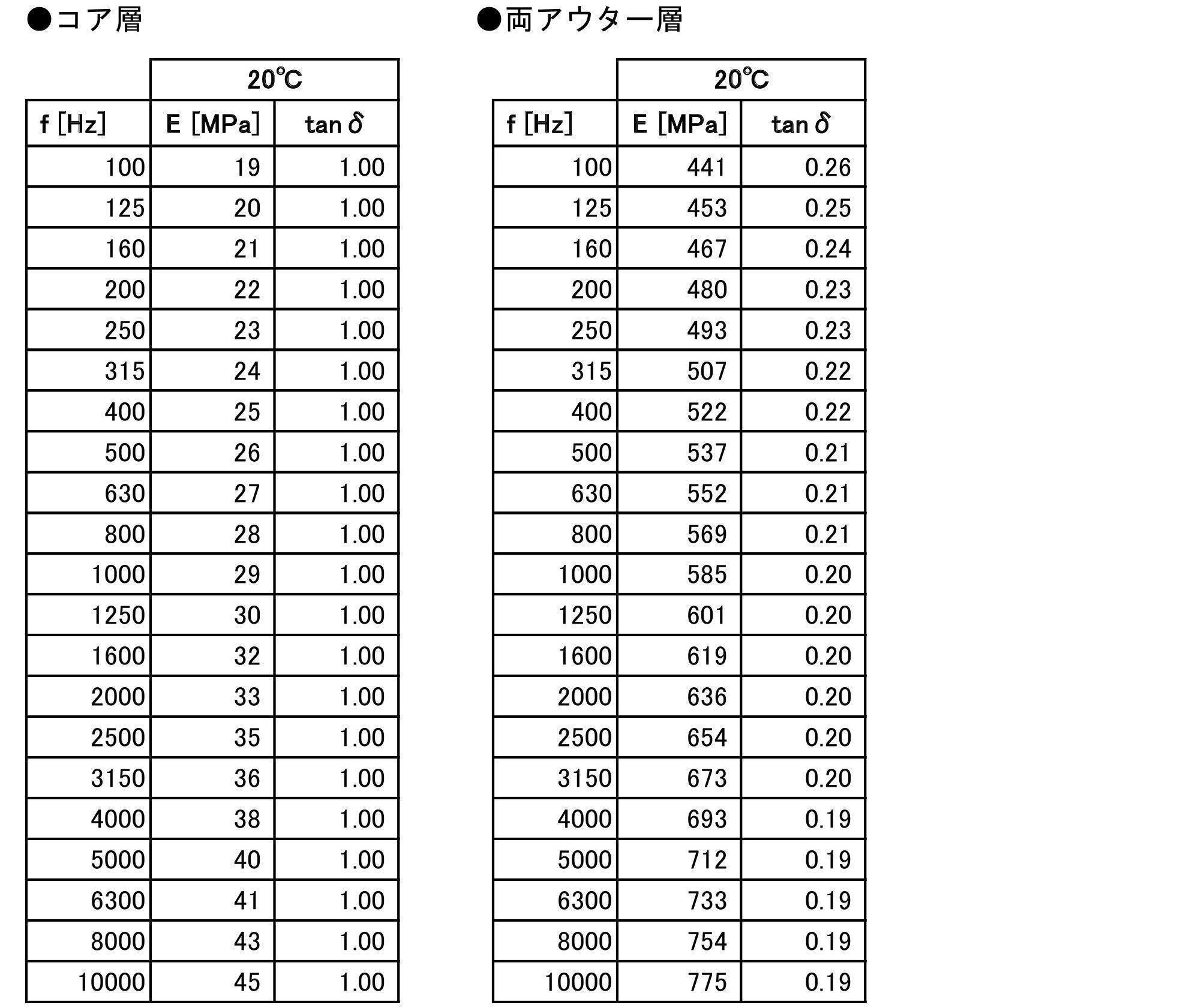
- the Young's modulus of the outer layer is 560 MPa, and tan ⁇ is 0.26 (temperature 20 ° C., frequency 100 Hz).
- Table 1 when the frequency is between 3150 and 5000 Hz, it can be seen that the sound transmission loss is improved as the Young's modulus of the interlayer film is decreased from 25 MPa to 12.5 MPa and 6.25 MPa.
- frequency dispersion measurement can be performed with a strain amount of 0.05% using a solid viscoelasticity measuring device DMA 50 manufactured by Metravib.
- the Young's modulus is a value measured by the above method.
- the measurement when the frequency is 200 Hz or less uses an actual measurement value.
- a calculation value based on the actual measurement value is used. This calculated value is based on a master curve calculated by using the WLF method from the actually measured value.
- the Young's modulus of the outer layer 132 is preferably large in order to improve sound insulation performance in a high frequency region, as will be described later, and is 560 MPa or more, 600 MPa or more, 650 MPa or more, 700 MPa or more at a frequency of 100 Hz and a temperature of 20 degrees. It can be set to 750 MPa or more, 880 MPa or more, or 1300 MPa or more.
- the upper limit of the Young's modulus of the outer layer 32 is not particularly limited, but can be set from the viewpoint of workability, for example. For example, it is empirically known that when it becomes 1750 MPa or more, workability, particularly cutting becomes difficult.
- the Young's modulus of the outer layer on the outer glass plate 1 side is preferable to make the Young's modulus of the outer layer on the outer glass plate 1 side larger than the Young's modulus of the outer layer on the inner glass plate 2 side.
- tan ⁇ of the core layer 131 can be set to 0.1 to 0.9 at a frequency of 100 Hz and a temperature of 20 ° C.
- tan ⁇ is in the above range, the sound insulation performance is improved.
- Table 2 shows the sound insulation performance of laminated glass having an intermediate film composed of an outer glass plate and an inner glass plate made of clear glass, and an outer layer positioned on both sides of the core layer and the core layer. Show.
- the thickness of the outer glass plate is 2.0 mm
- the thickness of the inner glass plate is 1.3 mm
- the thickness of the intermediate film is 0.10 mm for the core layer and 0.33 mm for the outer layer, for a total of 0.76 mm.
- the Young's modulus of the core layer and the outer layer at this time is 12.5 MPa and 560 MPa, respectively (measured at a frequency of 100 Hz and a temperature of 20 ° C.).
- Table 2 below shows sound transmission loss when the frequency is between 1250 and 10000 Hz. Specifically, sound transmission loss is calculated when tan ⁇ (measured at a frequency of 100 Hz and a temperature of 20 ° C.) of the interlayer film is 0.8, 1.2, and 1.6 (a calculation method is described in an example described later). The difference in sound transmission loss when tan ⁇ is 1.2 and 1.6 (unit is dB), based on the case where tan ⁇ is 0.8 (in the following table, it is 0). ). Note that tan ⁇ of the outer layer is 0.26. According to Table 2, when the frequency is between 5000 and 10,000 Hz, the sound transmission loss is improved as the tan ⁇ of the intermediate film increases from 0.8 to 1.2, 1.6. .
- each of the layers 131 and 132 is not particularly limited, but it is necessary that the material has at least a Young's modulus in the above range.
- the outer layer 132 can be made of polyvinyl butyral resin (PVB). Polyvinyl butyral resin is preferable because it is excellent in adhesiveness and penetration resistance with each glass plate.
- the core layer 131 can be made of an ethylene vinyl acetate resin (EVA) or a polyvinyl acetal resin softer than the polyvinyl butyral resin constituting the outer layer. By sandwiching the soft core layer between them, the sound insulation performance can be greatly improved while maintaining the same adhesion and penetration resistance as the single-layer resin intermediate film.
- the hardness of the polyvinyl acetal resin is controlled by (a) the degree of polymerization of the starting polyvinyl alcohol, (b) the degree of acetalization, (c) the type of plasticizer, (d) the addition ratio of the plasticizer, etc. Can do. Therefore, by appropriately adjusting at least one selected from these conditions, a hard polyvinyl butyral resin used for the outer layer 132 and a soft polyvinyl butyral resin used for the core layer 131 even if the same polyvinyl butyral resin is used. Can be made separately.
- the hardness of the polyvinyl acetal resin can also be controlled by the type of aldehyde used for acetalization, coacetalization with a plurality of aldehydes or pure acetalization with a single aldehyde. Although it cannot generally be said, the polyvinyl acetal resin obtained by using an aldehyde having a large number of carbon atoms tends to be softer.
- the core layer 131 has an aldehyde having 5 or more carbon atoms (for example, n-hexylaldehyde, 2-ethylbutyraldehyde, n-heptylaldehyde, n-octylaldehyde) and a polyvinyl acetal resin obtained by acetalization with polyvinyl alcohol can be used.
- a predetermined Young's modulus it is not limited to the said resin.
- the total thickness of the intermediate film 13 is not particularly limited, but is preferably 0.3 to 6.0 mm, more preferably 0.5 to 4.0 mm, and 0.6 to 2.0 mm. It is particularly preferred.
- the thickness of the core layer 131 is preferably 0.1 to 2.0 mm, and more preferably 0.1 to 0.6 mm.
- the thickness of each outer layer 132 is preferably 0.1 to 2.0 mm, and more preferably 0.1 to 1.0 mm.
- the total thickness of the intermediate film 13 can be made constant, and the thickness of the core layer 131 can be adjusted therein.
- the thickness of the core layer 131 and the outer layer 132 can be measured as follows, for example. First, the cross section of the laminated glass is enlarged and displayed by 175 times using a microscope (for example, VH-5500 manufactured by Keyence Corporation). And the thickness of the core layer 131 and the outer layer 132 is specified visually, and this is measured. At this time, in order to eliminate visual variation, the number of measurements is set to 5 times, and the average value is defined as the thickness of the core layer 131 and the outer layer 132. For example, an enlarged photograph of the laminated glass as shown in FIG. 7 is taken, and the core layer 131 and the outer layer 132 are specified in this and the thickness is measured.
- the thickness of the core layer 131 and the outer layer 132 of the intermediate film 13 does not need to be constant over the entire surface, and can be a wedge shape for laminated glass used for a head-up display, for example.
- the thickness of the core layer 131 and the outer layer 132 of the intermediate film 13 is measured at the position where the thickness is the smallest, that is, the lowermost side portion of the laminated glass.
- the intermediate film 13 is wedge-shaped, the outer glass plate and the inner glass plate are not arranged in parallel, but such arrangement is also included in the glass plate in the present invention.
- the arrangement of the outer glass plate 11 and the inner glass plate 12 when the intermediate film 13 using the core layer 131 and the outer layer 132 whose thickness is increased at a change rate of 3 mm or less per 1 m is used. including.
- the method for producing the intermediate film 13 is not particularly limited.
- the resin component such as the polyvinyl acetal resin described above, a plasticizer, and other additives as necessary are blended and kneaded uniformly, and then each layer is collectively And a method of laminating two or more resin films prepared by this method by a pressing method, a laminating method or the like.
- the resin film before lamination used in a method of laminating by a press method, a laminating method or the like may have a single layer structure or a multilayer structure.
- the intermediate film 13 can be formed of a single layer in addition to the above-described plural layers.
- the laminated glass according to the present embodiment is used for a windshield for a vehicle front safety system using a camera.
- the front vehicle is photographed by receiving visible light or infrared light, and the speed and distance between the vehicles ahead are measured. Therefore, the laminated glass is required to achieve a light transmittance of a predetermined range of wavelengths.
- infrared camera that calculates the speed of the vehicle ahead and the distance between the vehicles.
- the measuring method of the transmittance follows ISO9050.
- the manufacturing method of the said laminated glass is not specifically limited, The manufacturing method of a conventionally well-known laminated glass is employable.
- the mask layer 2 is formed on the inner glass plate 12 as described later.
- the inner glass plate 12 is heated to about 650 degrees by passing through a heating furnace, the inner glass plate 12 is molded into a curved surface by a molding die.
- the curved surface shape may have a curvature only in one direction, or may have a curvature in a plurality of directions.
- windshield is obtained by performing slow cooling outside a heating furnace.
- the outer glass plate 1 is similarly formed.
- a flat glass plate 10 on which a mask layer is formed is placed on a ring-shaped (frame-shaped) mold 900.
- the mold 900 is disposed on the transport table 901, and the transport table 901 passes through the heating furnace 902 and the slow cooling furnace 903 with the glass plate 10 placed on the mold 900. Since the mold 900 is ring-shaped, the glass plate 10 passes through the heating furnace 902 with only the peripheral edge portion supported.
- the inside of the glass plate 10 is curved downward from the peripheral edge by its own weight, and is formed into a curved surface. Subsequently, the glass plate 10 is carried into the slow cooling furnace 503 from the heating furnace 902, and a slow cooling process is performed. Thereafter, the glass plate 10 is taken out of the slow cooling furnace 903 and allowed to cool.
- molding method other than this is also possible, for example, after carrying out from the heating furnace 902, the glass plate 10 can also be shape
- the intermediate film 13 is subsequently sandwiched between the outer glass plate 1 and the inner glass plate 12, put into a rubber bag, and sucked under reduced pressure. While pre-adhering at about 70-110 ° C. Other pre-adhesion methods are possible.
- the intermediate film 13 is sandwiched between the outer glass plate 11 and the inner glass plate 12 and heated at 45 to 65 ° C. in an oven. Subsequently, this laminated glass is pressed by a roll at 0.45 to 0.55 MPa. Next, the laminated glass is again heated at 80 to 105 ° C. in an oven and then pressed again with a roll at 0.45 to 0.55 MPa. Thus, preliminary adhesion is completed.
- the laminated glass that has been pre-adhered is subjected to main bonding by an autoclave at, for example, 8 to 15 atm and 100 to 150 ° C.
- the main bonding can be performed under the conditions of 14 atm and 145 ° C.
- the laminated glass according to the present embodiment is manufactured.
- a glass plate when using one glass as a glass plate, what is necessary is just to use one sheet among the glass mentioned above.
- the manufacturing method of a glass plate is also the same. After forming a mask layer on the inner surface of the glass plate, heating is performed, and thereafter, it is formed into a curved surface.
- the mounting angle of the laminated glass is preferably 45 degrees or less from the vertical.
- a mask layer 2 as shown in FIG. 9 is formed adjacent to the glass plate 1.
- the mask layer 2 is a region for preventing the glass plate 1 from being seen from the outside, such as an adhesive applied when the glass plate 1 is attached to the vehicle body, and the peripheral mask layer formed on the outer peripheral edge of the glass plate 1.
- 21 and the peripheral mask layer 21 include a center mask layer 22 extending downward from the center of the upper edge of the glass plate 1.
- the measurement unit 4 described above is attached to the center mask layer 22.
- the measurement unit 4 only needs to be arranged so that the light emitted from the sensor 5 passes through the center of the opening and can receive the reflected light from the preceding vehicle and the obstacle.
- These mask layers 2 can be formed of various materials, but are not particularly limited as long as they can shield the field of view from the outside of the vehicle. For example, dark ceramic such as black is applied to the glass plate 1. Can be formed.
- the center mask layer 22 is formed in a rectangular shape extending in the vertical direction, and two openings arranged in the vertical direction, that is, an upper opening 231 and a lower opening 232 are formed. Both the upper opening 231 and the lower opening 232 are formed in a trapezoidal shape, but the width of the lower opening 232 in the left-right direction is about half that of the upper opening 231. However, the length in the vertical direction is substantially the same.
- the size of the opening is not particularly limited.
- the upper opening 231 can be about 58 mm in length and about 58 mm in width
- the lower opening 232 can be about 52 mm in length and about 27 mm in width.
- the center mask layer 22 is divided into three regions, an upper region 221 above the upper opening 231, a lower region 222 including both openings 231 and 232 below the upper region 221, and the side of the lower region 222. It is composed of small rectangular side regions 223 formed in the part.
- the upper region 221 is formed of one layer by a first ceramic layer 241 made of black ceramic.
- the lower region 222 is formed of three layers including the first ceramic layer 241, the silver layer 242, and the second ceramic layer 243 that are laminated from the inner surface of the glass plate 1.
- the silver layer 242 is made of silver, and the second ceramic layer 243 is made of the same material as the first ceramic layer 241.
- region 223 is formed with two layers, the 1st ceramic layer 241 and the silver layer 242, which are laminated
- the lowermost first ceramic layer 241 is common in each region, and the second silver layer 242 is common in the lower region 222 and the side region 223.
- the center mask layer 22 can be formed as follows, for example. First, the 1st ceramic layer 241 is apply
- the ceramic layers 241 and 243 can be formed of various materials.
- the ceramic layers 241 and 243 can have the following composition.
- Main component Copper oxide, Chromium oxide, Iron oxide and Manganese oxide * 2
- Main component Bismuth borosilicate, Zinc borosilicate
- the silver layer 242 is not particularly limited, but can be, for example, the following composition.
- the screen printing conditions may be, for example, polyester screen: 355 mesh, coat thickness: 20 ⁇ m, tension: 20 Nm, squeegee hardness: 80 degrees, mounting angle: 75 °, printing speed: 300 mm / s, and drying
- the ceramic layer and the silver layer can be formed by drying at 150 ° C. for 10 minutes in a furnace.
- what is necessary is just to repeat screen printing and drying mentioned above, when laminating
- FIG. 12 is a plan view of parts constituting the measurement unit.
- the measurement unit 4 is connected to a bracket 42 fixed to the inner surface of the glass plate 1, a frame-shaped cover base 41 fixed around the bracket 42, a sensor (information acquisition device) 5 supported by the bracket, and the sensor.
- a harness (not shown) and a cover 43 fixed to the cover base 41 and covering the bracket 42, the sensor 5, and the harness from the vehicle inner side are configured.
- the bracket 42 is formed in a rectangular shape, and is fixed to the center mask layer 22 described above with an adhesive.
- An opening 421 is formed in the center of the bracket 42, and the opening 421 is formed to have a size including the two openings 231 and 232 of the center mask layer 22.
- a cover base for fixing the cover 43 is fixed around the bracket 42 with double-sided tape. At this time, the cover base 41 is formed in such a size that the outer edge of the cover base 41 coincides with the outer edge of the center mask layer 22 or is disposed inside thereof.
- the rectangular sensor 5 is fixed to the bracket 42 so as to close the opening 421 of the bracket 42. Details of the sensor 5 will be described later.
- the cover 43 is attached to the cover base 41. That is, the outer edge of the cover 43 is fixed to the outer edge of the cover base 41 by fitting or the like.
- the cover 43 is attached so as to cover the bracket 42 and the sensor 5 so that the bracket 42 and the sensor 5 cannot be seen from the inside of the vehicle. Since the center mask layer 22 is formed, the measurement unit 4 cannot be seen from the outside of the vehicle except for the upper opening 231 and the lower opening 232.
- FIG. 13 is a sectional view of the sensor.
- the sensor 5 includes a housing 51 having a triangular shape in a side view, and the front surface of the housing 51 is disposed so as to coincide with the opening 421 of the bracket 42. It comes in contact with the inner surface.
- the interior of the casing 51 is partitioned into an upper space 501 having a triangular shape in side view and a lower space 502 having a trapezoidal shape in side view, and the front surface of the casing 51 communicates with the upper space and the lower space.
- a front opening 52 is formed.
- a connector 53 is attached to the back side of the casing 51 and is used for connection to an external device.
- a first support portion 54 is disposed in the upper space 501, and a first control board 541 and a light receiving lens 542 are disposed in the first support portion 54 from the rear to the front.
- a light receiving element 543 is mounted on the first control board 541 so as to receive laser light that has passed through the light receiving lens 542 and convert it into an electrical signal. This electric signal is amplified by the first control board 541 and transmitted to the second control board 56 described later.
- the light receiving lens 542 is arranged so as to face the outside through the upper opening 231 of the center mask layer 22 from the front opening 52 described above.
- the position and size of the upper opening 231, the position of the sensor 5, and the like are adjusted so that the passage path of light received by the light receiving element 543 passes through the center of the upper opening 231.
- the distance s1 between the laser (light) passing range X and the periphery of the upper opening 231 is preferably 4 mm or more, and more preferably 6 mm or more. preferable.
- reflected light from multiple directions reflected from the preceding vehicle or obstacle passes through the center of the upper opening 231 and the light receiving element 543 receives the reflected light.
- the second support portion 55 is disposed in the lower space 502, and the laser light emitting element 551 and the irradiation lens 552 are supported on the second support portion 55 in this order from the rear to the front.
- the laser light emitting element 551 emits laser light having a wavelength of 850 nm to 980 nm, such as a laser diode
- the irradiation lens 552 is a lens that shapes the laser light from the laser light emitting element 551 into a predetermined beam shape. It is.
- the irradiation lens 552 is disposed so as to face the outside from the front opening 52 of the housing 51 through the lower opening 232 of the center mask layer 22.
- the position and size of the lower opening 232 and the position of the sensor 5 are adjusted so that the passage path of the laser light emitted from the laser light emitting element 551 passes through the center of the lower opening 232.
- the distance s2 between the laser (light) passing range Y and the periphery of the lower opening 232 is preferably 4 mm or more, and more preferably 6 mm or more. preferable.
- a second control board 56 is disposed on the upper surface of the second support portion 55, and drives the laser light emitting element 551, processes an electric signal transmitted from the first control board 541, and the like.
- the first control board 541 transmits a pulse of laser light from the laser light emitting element 551. Then, the distance between the preceding vehicle or the obstacle and the own vehicle is calculated based on the time until the reflected light reflected by the preceding vehicle or the obstacle is received by the light receiving element 543. The calculated distance is transmitted to an external device via the connector 53 and used for brake control and the like.
- the antenna is provided on a glass plate for radio and digital television.
- the antenna 60 is formed in an L shape extending from a part of the upper side to a part of the right side of the inner surface of the glass plate 1.
- Can do As a manufacturing method, it can form by screen-printing on a glass plate with the same material as the silver layer of a mask layer, for example.
- a mask layer it is printed on a glass plate before being conveyed to a heating furnace.
- the mask layer 2 is formed adjacent to the glass plate 1. Thereafter, the glass plate 1 is heated and molded. At this time, since the mask layer 2 is a dark color such as black, the amount of heat absorbed in the glass plate 1 is larger than that of a region where the mask layer 2 is not formed, for example, the upper opening 231 and the lower opening 232. Become. The mask layer 2 and the glass plate 1 have different thermal expansion coefficients.
- the linear expansion coefficient of the mask layer (ceramic) 2 as described above is 70 ⁇ 10 ⁇ 7 to 100 ⁇ 10 ⁇ 7 / ° C.
- the linear expansion coefficient of glass is 1 ⁇ 10 ⁇ 6 to 10 ⁇ 10 ⁇ 6 / ° C. Therefore, in the region where the mask layer 2 is formed, compressive stress and tensile stress are generated at the time of molding, and the curvature of the glass surfaces of the outer glass plate and the inner glass plate is different. Distortion occurs near the boundary between the opening 231 and the lower opening 232.
- the distortion is more pronounced in the laminated glass having different thicknesses because it bends more than the outer glass plate 11 near the boundary of the inner glass plate 12. become.
- the light may be refracted due to distortion or the like, and there is a possibility that it cannot be irradiated accurately or cannot be received.
- the path X related to the irradiation and reception of the laser light passes through the vicinity of the center of the upper opening 231 and the lower opening 232 so as to avoid the distortion region.
- the laser beam can be prevented from being affected by distortion such as refraction.
- laser light irradiation and light reception can be performed accurately, and the inter-vehicle distance can be calculated accurately.
- the silver layer 242 is formed on the mask layer 2, it is possible to shield the electromagnetic wave emitted from the sensor 5 from being emitted to the outside. Therefore, the electromagnetic wave from the sensor 5 prevents noise from entering audio (video) such as AM (long wave / medium wave / short wavelength) / FM (frequency over ultra short wavelength) radio and digital TV (frequency 470-720 MHz). can do.
- audio video
- FM frequency over ultra short wavelength
- digital TV frequency 470-720 MHz
- the silver layer 242 is effective as an electromagnetic wave shielding function.
- the distance from the sensor 5 is closer, and electromagnetic waves are more affected. Since it is easy to receive, formation of the silver layer 242 is effective.
- the silver layer 242 is sandwiched between the black ceramic layers 241, 243, the silver layer 242 is prevented from being seen from outside and inside the vehicle. Therefore, even if the silver layer 242 is formed, the appearance is not affected. Furthermore, since the center mask layer 22 is covered with a bracket, a cover, etc., an electrical influence on the outside can be prevented.
- the following modifications are possible.
- the present invention is not limited to this, and the inter-vehicle distance can be measured by irradiating light and receiving the reflected light. If it is a thing, it will not specifically limit.
- the senor 5 for measuring the inter-vehicle distance is used as the information acquisition device of the present invention, but the present invention is not limited to this, and various information acquisition devices can be used. That is, there is no particular limitation as long as light is emitted and / or received in order to acquire information from outside the vehicle.
- a visible light and / or infrared camera for measuring the distance between vehicles a light receiving device for receiving a signal from outside the vehicle such as an optical beacon, a camera using visible light and / or infrared light that reads a white line of a road in an image, etc.
- the present invention can be applied to various devices.
- the center mask layer has one opening.
- a plurality of openings can be provided depending on the type of light.
- the information acquisition device may or may not be in contact with the glass.
- the camera photographing range (visible light or infrared light passing range Z) is adjusted as follows with respect to the opening 25 of the center mask layer 22. That is, as shown in FIG. 16, the distance s3 between the periphery of the photographing range of the camera 80 and the periphery of the opening is preferably 4 mm or more, and more preferably 6 mm or more.
- Mask layer> Since this embodiment uses a camera unit, the configuration of the center mask layer of the mask layer is different from that of the first embodiment.
- the camera unit 4 should just be arrange
- FIG. 17 is an enlarged plan view of the center mask layer
- FIG. 18 is a sectional view taken along line BB of FIG.
- the center mask layer 22 is formed in a rectangular shape extending in the vertical direction, and a rectangular opening 231 is formed therebelow.
- the size of the opening 231 is not particularly limited.
- the opening 231 can be about 58 mm in length and about 58 mm in width.
- the center mask layer 22 is divided into three regions, an upper region 221 above the opening 231, a lower region 222 including the opening 231 below the upper region 221, and the lower portion It is composed of small rectangular side regions 223 formed on the sides of the region 222. Since this is the same as in the first embodiment,
- FIG. 19 is a cross-sectional view of the windshield.
- the camera unit 4 includes a housing 41 fixed to the glass plate 1 and a camera (photographing device) 42 built in the housing 41.
- the housing 41 is disposed so as to face the center mask layer 22, and an opening 43 is formed at a position facing the opening 231 of the center mask layer 22.
- the built-in camera 42 photographs the front of the vehicle through the opening 43 of the casing 41 and the opening 231 of the center mask layer 22.
- the field of view Z (view angle) of the camera 42 is adjusted so as to substantially coincide with the opening 231 of the center mask layer 22.
- An image processing device 8 is connected to the camera 42, and an image taken by the camera 42 is transmitted to the image processing device 8.
- the image processing apparatus 8 can be configured by a known computer or the like. Specifically, a storage unit 81 such as a memory, a hard disk, and an SSD, and an image processing unit 82 including a CPU or the like are provided. The image processing unit 82 virtually operates as a trimming unit 821 and an image analysis unit 822 by reading and executing a predetermined program from the storage unit 81, for example. These operations will be described later. Note that the image processing device 8 may be disposed in the camera unit 4 or may be disposed outside the camera unit 4. Various information analyzed by the image analysis unit 822 is transmitted to a drive control unit of the vehicle. For example, as will be described later, after calculating the inter-vehicle distance from the captured image, a braking device such as a brake can be controlled based on the inter-vehicle distance.
- a braking device such as a brake can be controlled based on the inter-vehicle distance.
- the operation of the camera unit 4 will be described.
- the front of the vehicle is shot by the camera 42.
- This image is transmitted to the image processing device 8 in real time.
- the trimming unit 821 of the image processing apparatus 8 trims the transmitted image.
- this trimming is performed on a region of the transmitted image corresponding to a region 232 (hereinafter referred to as a peripheral region) having a predetermined length from the periphery of the opening 231 of the center mask layer 22.
- the peripheral region 232 is preferably a region having a distance s1 from the periphery of the opening 231 of 4 mm or more, and more preferably a region of 6 mm or more.
- the image analysis unit 822 analyzes the image.
- image analysis methods For example, the number plate of the vehicle ahead is specified, and the size of the number plate is calculated from the photographed image. Then, the inter-vehicle distance is calculated from the size of the license plate and the speed of the vehicle. As described above, the calculated inter-vehicle distance is transmitted to the drive control unit that controls the braking device, and performs a braking operation as necessary.
- the mask layer 2 is formed adjacent to the glass plate 1. Thereafter, the glass plate 1 is heated and molded. At this time, since the mask layer 2 is a dark color such as black, the amount of heat absorbed in the glass plate 1 is larger than that of a region where the mask layer 2 is not formed, for example, the opening 231. Since the mask layer 2 and the glass plate 1 have different thermal expansion coefficients as described above, compressive stress and tensile stress are generated in the region where the mask layer 2 is formed. Due to the difference in the curvature of the glass surface of the glass plate, the glass plate 1 is distorted in the vicinity of the boundary between the upper opening 231 and the lower opening 232.
- the distortion is more pronounced in the laminated glass having different thicknesses because it bends more than the outer glass plate 11 near the boundary of the inner glass plate 12. become.
- the image when taking an image with the camera 42, if the image is taken as shown in FIG. 30 due to light being refracted by the distortion of the glass in the opening 231, the image cannot be accurately analyzed. There is a fear.
- a region corresponding to the peripheral region 232 of the opening 231 that is considered to be distorted is trimmed from the photographed image, and an image is obtained using the other images. Analysis is performed.
- image processing is performed using an image of a region where distortion is not generated, the image can be analyzed accurately, and thus the inter-vehicle distance and the like can be calculated accurately.
- the silver layer 242 is formed on the mask layer 2, it is possible to shield the electromagnetic wave emitted from the camera 42 from being emitted to the outside. This is the same as in the first embodiment.
- the thickness of the inner glass plate 2 is 0.6 to 2.0 mm, and the thickness of the outer glass plate 1 is 1.8 to 2.3 mm.
- Laminated glass is preferable. This also contributes to a wavelength of 30% to 80% for light having a wavelength of 700 to 800 nm. Therefore, it can be employed in a windshield for a safety system using a camera.
- the Young's modulus of the core layer of the intermediate film is 1 to 20 MPa at a frequency of 100 Hz and a temperature of 20 ° C.
- the Young's modulus of the outer layer is The frequency is preferably 560 MPa or more at a frequency of 100 Hz and a temperature of 20 ° C.
- the mask layer 2 has a three-layer structure as described above, but is not limited to this. That is, in the above embodiment, the silver layer 242 is provided in order to shield electromagnetic waves, but other materials such as a method of providing a single layer in which silver and a ceramic layer are mixed, or an electromagnetic wave can be shielded. Copper, nickel, etc. may be laminated. In addition, the silver layer 242 is sandwiched between ceramic layers so that the silver layer 242 cannot be seen from the outside. However, in addition to covering with the ceramic layer, a member such as the cover described above can also be used. Further, it is not always necessary to provide an electromagnetic wave shielding layer, and at least a layer that cannot be seen from the outside may be formed.
- a silver layer can be applied to hide the above-described region where distortion occurs. Further, the silver layer can be formed not only on the mask layer but also in a region within a distance of s1 or s2 from the opening peripheral edges 231 and 232 (a region where distortion occurs). That is, it can also be formed in at least part of the mask layer and the region where distortion occurs.
- the mask layer 2 can be other than black, and is not particularly limited as long as it is a dark color such as brown, gray, or dark blue that blocks the field of view from the outside of the vehicle and prevents the inside of the vehicle from being seen.
- the opening formed in the mask layer was a closed opening in which the entire circumference was surrounded by the mask layer in each of the above embodiments, but the opening in the present invention does not necessarily have to be closed in the entire circumference. Some may be opened. For example, as shown in FIG. 21, an opening 231 that opens downward may be used. Further, the position is not limited to the lower side, and any position around the opening may be opened.
- the present invention is not limited to this embodiment.
- Configuration of glass plate A laminated glass in which an outer glass plate and an inner glass plate were made of green glass having a thickness of 2 mm, and a single-layer interlayer film was disposed between them.
- Mask layer It was set as the composition of Table 3 and Table 4 mentioned above. The upper opening was 58 mm long and 72 mm wide, and the lower opening was 29 mm long and 72 mm wide.
- a first ceramic layer, a silver layer, and a second ceramic layer were screen-printed on the inner surface of the inner glass plate to form a mask layer. Thereafter, it was baked to 650 ° C. in a heating furnace and molded into a curved shape with a molding die as shown in FIG. 8, and gradually cooled after being taken out from the heating furnace.
- the horizontal axis represents the length in the surface direction of the glass plate
- the vertical axis represents the lens power (mili diopter: reciprocal of focal length).
- the method for measuring the lens power is as follows. First, light is projected onto a glass plate in a dark room, and a shadow is formed on the screen behind the glass plate. At this time, if there is a convex lens on the glass plate, the light is condensed and the shadow on the screen becomes bright. On the other hand, it becomes dark when there is a concave lens on the glass plate.
- the lens power of the glass plate can be obtained by arranging the target glass plate and measuring the brightness on the screen over the entire surface of the glass.
- FIG. 1 This photograph was taken on a glass plate having a trapezoidal opening in the mask layer, based on the perspective distortion test of JIS R3212. From the figure, in the peripheral region within 4 mm from the boundary between the mask layer 2 and the opening, the perfect circle is deformed and is distorted into an elliptical shape. On the other hand, it can be seen that the vicinity of the center of the opening (region excluding 4 mm from the boundary) is closer to a perfect circle than the vicinity of the boundary.
- the light irradiation and / or received light passing range is distorted as described above. It is necessary to avoid being placed in a large area. Further, when performing image analysis, it is necessary not to use an area corresponding to the above-described peripheral area in the captured image.
- Each glass plate was formed of the above-described clear glass.
- the intermediate film was comprised with the core layer and a pair of outer layer which clamps this.
- the thickness of the intermediate film was 0.76 mm
- the thickness of the core layer was 0.1 mm
- the thicknesses of both outer layers were 0.33 mm.
- the Young's modulus of both outer layers was adjusted to 441 MPa (20 ° C., 100 Hz).
- the sound transmission loss was evaluated by simulation for the above examples and comparative examples.
- the simulation conditions are as follows.
- the simulation was performed using acoustic analysis software (ACTRAN, manufactured by Free Field technology).
- ACTRAN acoustic analysis software
- the sound transmission loss (transmitted sound pressure level / incident sound pressure level) of the laminated glass can be calculated by solving the following wave equation using the finite element method.
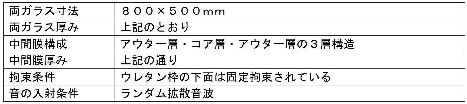
- Model setting The model of the laminated glass used by this simulation is shown in FIG.
- a laminated glass is defined in which an outer glass plate, an intermediate film, an inner glass plate, and a urethane frame are laminated in this order from the sound source side.
- the reason why the urethane frame is added to the model is that there is a considerable influence on the calculation result of sound transmission loss due to the presence or absence of the urethane frame, and between the laminated glass and the vehicle windshield. This is because it is generally considered that a urethane frame is used and bonded.
- Input condition 1 (dimensions, etc.)
- the size of the glass plate 800 ⁇ 500 mm
- the STL value tends to worsen because the larger the size, the larger the constrained portion and the greater the resonance mode.
- the tendency of the relative value for each frequency that is, the laminated glass made of glass plates with different thicknesses becomes worse in a predetermined frequency band than the laminated glass made of glass plates with the same thickness. The trend is the same.
- the random diffuse sound wave in Table 6 is a sound wave having a sound wave of a predetermined frequency transmitted with an incident angle in any direction with respect to the outer glass plate, and a sound source in a reverberation chamber for measuring sound transmission loss. Is assumed.
- Input condition 2 (property value)
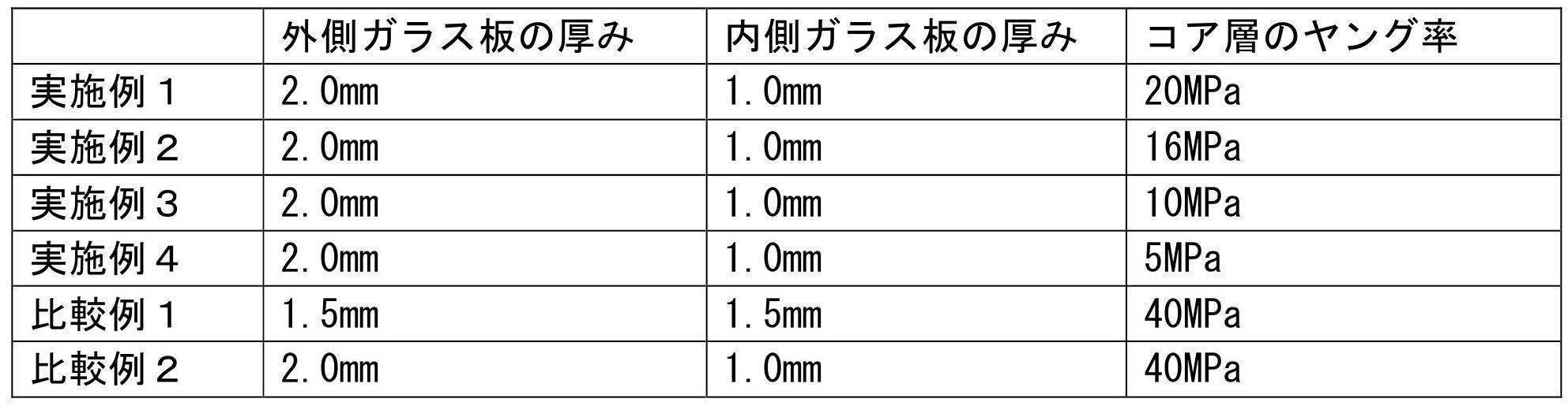
- the STL value due to the different thickness can be suppressed by setting the Young's modulus of the core layer to 20 MPa (20 ° C., 100 Hz) or less as in Examples 1 to 4. Further, as in Examples 2 to 4, by setting the Young's modulus of the core layer to 16 MPa (20 ° C., 100 Hz) or less, compared with Comparative Example 1 in which both glasses have the same thickness, in a frequency region of 2000 to 5000 Hz. Sound transmission loss is high.
- the laminated glass which concerns on an Example and a comparative example was prepared as follows. Here, the thickness of the core layer was changed and the sound transmission loss was calculated by the simulation method.
- the intermediate film was composed of three layers, and the thickness of the core layer and the outer layer was changed without changing the total thickness.
- the Young's modulus of the core layer was 10 MPa (20 ° C., 100 Hz), and the Young's modulus of the outer layer was 441 Mpa (20 ° C., 100 Hz).
- the thicknesses of the outer glass plate and the inner glass plate were 2.0 mm and 1.0 mm, respectively.
- the sound transmission loss was evaluated by simulation for the above examples and comparative examples. The results are as shown in FIG. According to the figure, it can be seen that when the thickness of the core layer is smaller than 0.1 mm, the sound transmission loss is reduced in the frequency range of 2000 to 5000 Hz. Therefore, in order to increase the sound insulation performance in the frequency range of 2000 to 5000 Hz that is easy for humans to hear, the thickness of the core layer is preferably set to 0.1 mm or more.
- the mounting angle of laminated glass was evaluated by a simulation in which the incident angle of sound was changed.
- the sound transmission loss was calculated by changing the angle from the vertical to 0 to 75 degrees.
- Each glass plate was formed of the above-described clear glass.
- the intermediate film was comprised with the core layer and a pair of outer layer which clamps this. The thickness of the intermediate film was 0.76 mm, the thickness of the core layer was 0.1 mm, and the thicknesses of both outer layers were 0.33 mm.
- the Young's modulus of the core layer was 10 MPa (20 ° C., 100 Hz), and the Young's modulus of both outer layers was 441 MPa (20 ° C., 100 Hz). Moreover, the thickness of the glass plate was 2.0 mm and 1.0 mm.
- Example 13 and 14 are shown in FIG.
- the Young's modulus of the core layer In the evaluation of the Young's modulus of the core layer described above, it was found that when the Young's modulus is 20 MPa or less, the sound transmission loss is increased in a frequency range of 2000 to 5000 Hz that is easy for humans to hear.
- the Young's modulus of the outer layer was changed while keeping the Young's modulus of the core layer constant. As a result, as shown in FIG. 28, it was found that in Example 14 where the Young's modulus of the outer layer was high, the sound transmission loss was high in a high frequency region of 5000 Hz or higher.
- the Young's modulus of the core layer is further lowered and the Young's modulus of the outer layer is increased.
- the sound transmission loss in the frequency region of 2000 to 5000 Hz is higher than those in Examples 13 and 14, but in Examples 13 and 14, it is higher than 5000 Hz.
- the sound transmission loss in the frequency domain is not high.
- the Young's modulus of the outer layer exceeds 1764 MPa, the sound transmission loss in a high frequency region of 5000 Hz or higher hardly increases.
Landscapes
- Engineering & Computer Science (AREA)
- Mechanical Engineering (AREA)
- Physics & Mathematics (AREA)
- General Physics & Mathematics (AREA)
- Optics & Photonics (AREA)
- Multimedia (AREA)
- Theoretical Computer Science (AREA)
- Joining Of Glass To Other Materials (AREA)
- Fittings On The Vehicle Exterior For Carrying Loads, And Devices For Holding Or Mounting Articles (AREA)
- Laminated Bodies (AREA)
- Surface Treatment Of Glass (AREA)
Abstract
Description
本発明に係るウインドシールドは、光の照射及び/または受光を行うことで車外からの情報を取得する情報取得装置が取り付け可能なウインドシールドであって、ガラス板と、前記ガラス板に形成され、車外からの視野を遮蔽するとともに、少なくとも1つの開口を有するマスク層と、を備え、前記ガラス板と前記マスク層の熱収縮率は相違し、前記ガラス板と前記マスク層は共に加熱されることにより成形され、前記成形により、前記ガラス板において前記開口の内周縁から中央側へ向かう所定の範囲に生じる歪みに対し、前記情報取得装置が、前記歪みの影響を低減するように、前記情報を利用可能に構成されている。
本発明は、光の照射及び/または受光を行うことで車外からの情報を取得する情報取得装置が配置可能なウインドシールドであって、車外からの視野を遮蔽するとともに少なくとも1つの開口を有するマスク層が積層されたガラス板を備え、前記ガラス板と前記マスク層の熱収縮率は相違し、前記ガラス板と前記マスク層は共に加熱されることにより成形され、前記光の照射及び/または受光における光の通過範囲が、前記マスク層の開口の中央付近を通過するように構成されており、前記情報取得装置は、前記ガラス板の車内側の面において、前記開口を通して前記情報を取得できるように配置されている。
本発明に係るウインドシールドは、車外からの視野を遮蔽するとともに少なくとも1つの開口を有するマスク層が積層されたガラス板と、前記ガラス板の車内側の面において、前記開口を介して車外の撮影を行うことができるように配置された撮影装置と、前記撮影装置で撮影された画像の処理を行う画像処理装置と、を備え、前記ガラス板と前記マスク層の熱収縮率は相違し、前記ガラス板と前記マスク層は共に加熱されることにより成形され、前記画像処理装置は、前記撮影装置によって前記開口を介して撮影された画像に対し、前記開口の周縁から中央側へ向かう所定の長さの範囲と対応する領域を利用せずに、前記画像の解析を行うように構成されている。
本発明に係るウインドシールドに車間距離の測定ユニットを取付けた場合の第1実施形態について、図面を参照しつつ説明する。図1は、本実施形態に係るウインドシールドの断面図、図2は図1の平面図である。図1及び図2に示すように、本実施形態に係るウインドシールドは、ガラス板1と、このガラス板1の車内側の面に形成されたマスク層2と、を備え、マスク層2に、車間距離の測定を行う測定ユニット4が取付けられている。以下、各部材について説明する。
<1-1.ガラス板の概要>
ガラス板1は、種々の構成が可能であり、例えば、複数のガラス板を有する合わせガラスで構成したり、あるいは一枚のガラス板により構成することもできる。合わせガラスを用いる場合には、例えば、図3に示すように、構成することができる。図3は合わせガラスの断面図である。
SiO2:70~73質量%
Al2O3:0.6~2.4質量%
CaO:7~12質量%
MgO:1.0~4.5質量%
R2O:13~15質量%(Rはアルカリ金属)
Fe2O3に換算した全酸化鉄(T-Fe2O3):0.08~0.14質量%
熱線吸収ガラスの組成は、例えば、クリアガラスの組成を基準として、Fe2O3に換算した全酸化鉄(T-Fe2O3)の比率を0.4~1.3質量%とし、CeO2の比率を0~2質量%とし、TiO2の比率を0~0.5質量%とし、ガラスの骨格成分(主に、SiO2やAl2O3)をT-Fe2O3、CeO2およびTiO2の増加分だけ減じた組成とすることができる。
続いて、中間膜13について説明する。中間膜13は、少なくとも一層で形成されており、一例として、図3に示すように、軟質のコア層131を、これよりも硬質のアウター層132で挟持した3層で構成することができる。但し、この構成に限定されるものではなく、コア層131と、外側ガラス板11側に配置される少なくとも1つのアウター層132とを有する複数層で形成されていればよい。例えば、コア層131と、外側ガラス板11側に配置される1つのアウター層132を含む2層の中間膜13、またはコア層131を中心に両側にそれぞれ2層以上の偶数のアウター層132を配置した中間膜13、あるいはコア層131を挟んで一方に奇数のアウター層132、他方の側に偶数のアウター層132を配置した中間膜13とすることもできる。なお、アウター層132を1つだけ設ける場合には、上記のように外側ガラス板11側に設けているが、これは、車外や屋外からの外力に対する耐破損性能を向上するためである。また、アウター層132の数が多いと、遮音性能も高くなる。


上記のように、本実施形態に係る合わせガラスは、カメラを用いた自動車の前方安全システム用のウインドシールドに用いられる。このような安全システムでは、前方の車両に対して可視光や赤外線を受光して撮影を行い、前方の自動車の速度や車間距離を計測する。そのため、合わせガラスには、所定範囲の波長の光の透過率を達成することが要求される。
上記合わせガラスの製造方法は、特に限定されず、従来公知の合わせガラスの製造方法を採用することができる。例えば、まず、内側ガラス板12に、後述するようにマスク層2を形成する。次に、内側ガラス板12を、加熱炉を通過させることで約650度まで加熱した後、成形型により曲面状に成形を行う。この場合の曲面形状は、一方向のみの曲率を有するものであってもよいし、複数の方向において曲率を有するものであってもよい。その後、加熱炉外で徐冷を行うことで、ウインドシールドが得られる。外側ガラス板1も同様に成形する。
ガラス板1に隣接して、図9に示すようなマスク層2が形成される。このマスク層2は、ガラス板1を車体に取付ける際の接着剤が塗布されたりするなど、外部から見えないようにするための領域であり、ガラス板1の外周縁に形成された周縁マスク層21と、この周縁マスク層21において、ガラス板1の上縁の中央から下方に延びるセンターマスク層22と、を備えている。そして、センターマスク層22には、上述した測定ユニット4が取付けられる。測定ユニット4は、センサー5から照射される光が開口の中心を通過し、先行車および障害物からの反射光を受光できる程度に配置されていればよい。これらマスク層2は、種々の材料で形成することができるが、車外からの視野を遮蔽できるものであれば特には限定されず、例えば、黒色などの濃色のセラミックをガラス板1に塗布することで形成することができる。
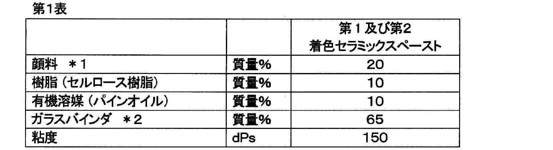
*2,主成分:ホウケイ酸ビスマス、ホウケイ酸亜鉛

図12に示すように、測定ユニット4は、以下のように構成されている。図12は、測定ユニットを構成するパーツの平面図である。この測定ユニット4は、ガラス板1の内面に固定されるブラケット42、ブラケット42の周囲に固定される枠状のカバーベース41、ブラケットに支持されるセンサ(情報取得装置)5、センサに接続するハーネス(図示省略)、及びカバーベース41に固定され、ブラケット42とセンサ5とハーネスを車内側から覆うカバー43に、により構成されている。
アンテナは、ラジオやデジタルテレビのために、ガラス板に設けられる。その態様は種々のものがあるが、例えば、図15に示すように、アンテナ60を、ガラス板1の車内側の面の上辺の一部から右辺の一部に亘るL字状に形成することができる。作製方法としては、例えば、マスク層の銀層と同じ材料で、ガラス板にスクリーン印刷することで形成することができる。また、マスク層と同様に、加熱炉に搬送される前にガラス板上に印刷される。
以上のように、本実施形態によれば、次の効果を得ることができる。上記のように、マスク層2は、ガラス板1に隣接して形成される。その後、ガラス板1は加熱され、成形が行われる。その際、マスク層2は、黒色等の濃色であるため、マスク層2が形成されていない領域、例えば、上部開口231及び下部開口232と比べると、ガラス板1における熱の吸収量が多くなる。そして、マスク層2とガラス板1は、熱膨張係数が異なっている。例えば、上述したによるマスク層(セラミック)2の線膨張係数は、70×10-7~100×10-7/℃であり、ガラスの線膨張係数は、1×10-6~10×10-6/℃である。そのため、マスク層2が形成された領域では成形時における圧縮応力や引張応力が発生し、また、外側ガラス板と内側ガラス板のガラス表面の曲率が相違することにより、ガラス板1には、上部開口231及び下部開口232との境界付近において、歪みが生じる。また、ウインドシールドが合わせガラスからなり、外側ガラス板11の厚みが内側よりも大きい場合、内側ガラス板12の境界付近では外側ガラス板11よりも大きく曲がるため、異厚合わせガラスでは歪みがより顕著になる。その結果、レーザ光を照射及び受光したときには、歪みによって光が屈折するなどして、正確に照射できなかったり、あるいは受光できないおそれがある。
次に、本発明の第2実施形態に係るウインドシールドについて説明する。本実施形態が第1実施形態と相違するのは、情報取得装置の構成である。すなわち、本実施形態においては、図1に示すウインドシールドにおいて、マスク層2に、カメラが内蔵されたカメラユニット4が取付けられている。そして、カメラユニット4において撮影された画像は、画像処理装置(図19参照)で処理され、車間距離などが算出される。以下では、第1実施形態と同じ構成については説明を省略し、主として相違部分であるカメラユニット及びマスク層の構成について説明する。
本実施形態では、カメラユニットを用いるため、第1実施形態とは、マスク層のセンターマスク層の構成が相違している。カメラユニット4は、後述する開口を通じて車両前方の撮影が行えるように配置されていればよいが、具体的には以下のように構成されている。
図19に示すように、カメラユニット4は、以下のように構成されている。図19は、ウインドシールドの断面図である。同図に示すように、カメラユニット4は、ガラス板1に固定される筐体41と、この筐体41に内蔵されるカメラ(撮影装置)42とを備えている。筐体41は、センターマスク層22と対向するように配置されており、センターマスク層22の開口231と対向する位置に、開口43が形成されている。そして、内蔵されたカメラ42は、筐体41の開口43及びセンターマスク層22の開口231を通じて、車両前方を撮影するようになっている。このとき、カメラ42の視野Z(画角)が、センターマスク層22の開口231と概ね一致するように調整されている。また、カメラ42には画像処理装置8が接続されており、カメラ42で撮影された画像は画像処理装置8に送信される。
以上のように、本実施形態によれば、次の効果を得ることができる。上記のように、マスク層2は、ガラス板1に隣接して形成される。その後、ガラス板1は加熱され、成形が行われる。その際、マスク層2は、黒色等の濃色であるため、マスク層2が形成されていない領域、例えば、開口231と比べると、ガラス板1における熱の吸収量が多くなる。そして、マスク層2とガラス板1は、上述したとおり、熱膨張係数が異なるため、マスク層2が形成された領域では成形時における圧縮応力や引張応力が発生し、また、外側ガラス板と内側ガラス板のガラス表面の曲率が相違することにより、ガラス板1には、上部開口231及び下部開口232との境界付近において、歪みが生じる。また、ウインドシールドが合わせガラスからなり、外側ガラス板11の厚みが内側よりも大きい場合、内側ガラス板12の境界付近では外側ガラス板11よりも大きく曲がるため、異厚合わせガラスでは歪みがより顕著になる。その結果、カメラ42で撮影を行う際に、開口231内におけるガラスの歪みによって光が屈折するなどして、図30に示すような画像の撮影が行われると、画像の解析を正確に行えないおそれがある。
以上、本発明の実施形態について説明したが、本発明は上記実施形態に限定されるものではなく、その趣旨を逸脱しない限りにおいて、種々の変更が可能である。
<1.マスク層の開口周縁の歪みの評価>
まず、以下のようなマスク層が形成されたガラス板を準備した。
(1) ガラス板の構成:外側ガラス板及び内側ガラス板を厚み2mmのグリーンガラスで構成し、これらの間に単層の中間膜を配置した合わせガラスとした。
(2) マスク層:上述した表3及び表4の組成とした。上側開口は、縦58mm、横72mm、下側開口は縦29mm、横72mmとした。
(3) ガラス板の作製:内側ガラス板の車内側の面に、第1セラミック層、銀層、及び第2セラミック層をスクリーン印刷し、マスク層を形成した。その後、図8に示すような成形型で、加熱炉で650℃に焼成し曲面状に成形し、加熱炉から搬出後に徐冷した。
以下の通り、実施例及び比較例に係る合わせガラスを準備した。

(1) モデルの設定
本シミュレーションで用いた合わせガラスのモデルを図24に示す。このモデルでは、音の発生源側から外側ガラス板、中間膜、内側ガラス板、ウレタン枠の順で積層した合わせガラスを規定している。ここで、ウレタン枠をモデルに追加しているのは、ウレタン枠の有無により音響透過損失の算出結果に少なからず影響があると考えられる点、及び、合わせガラスと車両のウインドシールドの間にはウレタン枠が用いられて接着していることが一般的である点を考慮したためである。
(2) 入力条件1(寸法等)
(3) 入力条件2(物性値)

主な周波数毎に異なった値を用いた。これは、コア層及び両アウター層は粘弾性体のため、粘性効果によりヤング率は周波数依存性が強いためである。なお、温度依存性も大きいが、今回は温度一定(20℃)を想定した物性値を用いた。
以下の通り、実施例及び比較例に係る合わせガラスを準備した。ここでは、コア層の厚みを変化させ、音響透過損失を上記シミュレーション方法により算出した。中間膜は3層で構成し、総厚を変化させず、コア層とアウター層の厚みを変化させた。コア層のヤング率は10MPa(20℃、100Hz),アウター層のヤング率は441Mpa(20℃、100Hz)とした。また、外側ガラス板及び内側ガラス板の厚みはそれぞれ2.0mm、1.0mmとした。
続いて、音の入射角を変化させたシミュレーションにより、合わせガラスの取付角度について評価を行った。ここでは、垂直からの角度を0~75度に変化させて音響透過損失を算出した。各ガラス板は、上述したクリアガラスで形成した。また、中間膜はコア層とこれを挟持する一対のアウター層で構成した。中間膜の厚みは0.76mm、コア層の厚みは0.1mm、両アウター層の厚みは0.33mmとした。コア層のヤング率は10MPa(20℃、100Hz),両アウター層のヤング率は441MPa(20℃、100Hz)とした。また、ガラス板の厚みは、2.0mm、1.0mmとした。

アウター層のヤング率に関する評価を行うため、以下の通り、実施例及び比較例に係る合わせガラスを準備した。ここでは、外側ガラス及び内側ガラスの厚みを一定にした上で、中間膜のアウター層及びコア層のヤング率を変化させ、音響透過損失を上記シミュレーション方法により算出した。各ガラス板は、上述したクリアガラスで形成し、中間膜はコア層とこれを挟持する一対のアウター層で構成した。中間膜の厚みは0.76mm、コア層の厚みは0.1mm、両アウター層の厚みは0.33mmとした。

2 マスク層
22 センターマスク層
241 第1セラミック層(第1の視野遮蔽膜)
242 銀層(電磁波遮蔽膜)
243 第2セラミック層(第2の視野遮蔽膜)
42 カメラ(撮影装置)
5 センサ(情報取得装置)
Claims (16)
- 光の照射及び/または受光を行うことで車外からの情報を取得する情報取得装置が取り付け可能なウインドシールドであって、
ガラス板と、
前記ガラス板に形成され、車外からの視野を遮蔽するとともに、少なくとも1つの開口を有するマスク層と、
を備え、
前記ガラス板と前記マスク層の熱収縮率は相違し、前記ガラス板と前記マスク層は共に加熱されることにより成形され、
前記成形により、前記ガラス板において前記開口の内周縁から中央側へ向かう所定の範囲に生じる歪みに対し、前記情報取得装置が、前記歪みの影響を低減するように、前記情報を利用可能に構成されている、ウインドシールド。 - 前記光の照射及び/または受光における光の通過範囲が、前記マスク層の開口の中央付近を通過するように構成されており、
前記情報取得装置は、前記ガラス板の車内側の面において、前記開口を通じて前記情報を取得できるように構成されている、請求項1に記載のウインドシールド。 - 前記光の通過範囲は、前記開口の周縁から少なくとも4mm離れている、請求項2に記載のウインドシールド。
- 前記マスク層の少なくとも一部は、黒色である、請求項2または3に記載のウインドシールド。
- 前記マスク層及び歪みが生じている領域の少なくとも一部において、前記情報取得装置が取付けられる領域の少なくとも一部には、電磁波遮蔽膜が形成されている、請求項2から4のいずれかに記載のウインドシールド。
- 前記マスク層及び歪みが生じている領域の少なくとも一部は、第1の視野遮蔽膜、前記電磁波遮蔽膜、及び第2の視野遮蔽膜が、外部から車内側へこの順で配置されていることで構成されている、請求項5に記載のウインドシールド。
- 前記情報取得装置は、
前記ガラス板の車内側において、前記開口を介して車外の撮影を行うことができるように配置された撮影装置と、
前記撮影装置で撮影された画像の解析を行う画像処理装置と、
を備え、
前記画像処理装置は、前記撮影装置によって前記開口を介して撮影された画像において、前記所定の範囲と対応する領域を利用せずに、当該画像の解析を行うように構成されている、請求項1に記載のウインドシールド。 - 前記領域は、前記画像において、前記開口の周縁から中央側へ4mm以上の範囲に対応する領域である、請求項7に記載のウインドシールド。
- 前記画像処理装置は、前記画像に対して前記領域をトリミングし、当該トリミングが行われた後の画像に対し前記解析を行う、請求項7または8に記載のウインドシールド。
- 前記マスク層の少なくとも一部は、黒色である、請求項7から9のいずれかに記載のウインドシールド。
- 前記ガラス板は、外側ガラス板、当該外側ガラス板と対向配置される内側ガラス板、及び前記外側ガラス板と内側ガラス板との間に配置される中間膜を備えている、請求項7から10のいずれかに記載のウインドシールド。
- 前記中間膜は、コア層と、前記コア層よりも硬度が高く当該コア層を挟持する一対のアウター層と、を備えている、請求項11に記載のウインドシールド。
- 前記コア層は、周波数100Hz,温度20℃で、ヤング率が1~20MPaである、請求項12に記載のウインドシールド。
- 前記アウター層は、周波数100Hz,温度20℃で、ヤング率が560MPa以上である、請求項12または13に記載のウインドシールド。
- 前記マスク層において、前記撮影装置が取付けられる領域の少なくとも一部に
は、電磁波遮蔽膜が形成されている、請求項7から14のいずれかに記載のウインドシールド。 - 前記マスク層の少なくとも一部は、第1の視野遮蔽膜、前記電磁波遮蔽膜、及び第2の視野遮蔽膜が、外部から車内側へこの順で配置されていることで構成されている、請求項15に記載のウインドシールド。
Priority Applications (5)
| Application Number | Priority Date | Filing Date | Title |
|---|---|---|---|
| CN201580014195.8A CN106103158B (zh) | 2014-03-14 | 2015-03-16 | 挡风玻璃 |
| EP15761431.4A EP3118036B1 (en) | 2014-03-14 | 2015-03-16 | Windshield |
| PL15761431T PL3118036T3 (pl) | 2014-03-14 | 2015-03-16 | Przednia szyba |
| US15/125,864 US10336163B2 (en) | 2014-03-14 | 2015-03-16 | Windshield |
| JP2016507867A JP6577456B2 (ja) | 2014-03-14 | 2015-03-16 | ウインドシールド |
Applications Claiming Priority (4)
| Application Number | Priority Date | Filing Date | Title |
|---|---|---|---|
| JP2014-052796 | 2014-03-14 | ||
| JP2014052796 | 2014-03-14 | ||
| JP2014-052795 | 2014-03-14 | ||
| JP2014052795 | 2014-03-14 |
Publications (1)
| Publication Number | Publication Date |
|---|---|
| WO2015137518A1 true WO2015137518A1 (ja) | 2015-09-17 |
Family
ID=54071952
Family Applications (1)
| Application Number | Title | Priority Date | Filing Date |
|---|---|---|---|
| PCT/JP2015/057778 WO2015137518A1 (ja) | 2014-03-14 | 2015-03-16 | ウインドシールド |
Country Status (6)
| Country | Link |
|---|---|
| US (1) | US10336163B2 (ja) |
| EP (1) | EP3118036B1 (ja) |
| JP (1) | JP6577456B2 (ja) |
| CN (1) | CN106103158B (ja) |
| PL (1) | PL3118036T3 (ja) |
| WO (1) | WO2015137518A1 (ja) |
Cited By (23)
| Publication number | Priority date | Publication date | Assignee | Title |
|---|---|---|---|---|
| JP2017061276A (ja) * | 2015-09-25 | 2017-03-30 | 日本板硝子株式会社 | ウインドシールド及びブラケット |
| JP2017071544A (ja) * | 2015-10-11 | 2017-04-13 | 日本板硝子株式会社 | 合わせガラス |
| WO2017065114A1 (ja) * | 2015-10-11 | 2017-04-20 | 日本板硝子株式会社 | 合わせガラス |
| JP2017081520A (ja) * | 2015-10-30 | 2017-05-18 | 日本板硝子株式会社 | ウインドシールド |
| EP3228455A1 (en) * | 2016-03-28 | 2017-10-11 | Asahi Glass Company, Limited | Laminated glass |
| JP2017197031A (ja) * | 2016-04-27 | 2017-11-02 | 旭硝子株式会社 | 車両用窓板 |
| WO2018016454A1 (ja) * | 2016-07-20 | 2018-01-25 | 日本板硝子株式会社 | 防曇性フィルム |
| EP3181534A4 (en) * | 2014-08-15 | 2018-03-21 | Nippon Sheet Glass Company, Limited | Laminated glass |
| JP2019001664A (ja) * | 2017-06-09 | 2019-01-10 | 日本板硝子株式会社 | 合わせガラス |
| EP3434472A1 (en) | 2017-07-26 | 2019-01-30 | Agc Inc. | Laminated glass for vehicle |
| JP2019026248A (ja) * | 2017-07-26 | 2019-02-21 | Agc株式会社 | 車両用合わせガラス |
| JPWO2017204291A1 (ja) * | 2016-05-26 | 2019-05-16 | 日本板硝子株式会社 | 合わせガラス |
| EP3395778A4 (en) * | 2015-12-25 | 2019-08-21 | Nippon Sheet Glass Company, Limited | LAMINATED GLASS |
| CN110248804A (zh) * | 2018-01-11 | 2019-09-17 | 法国圣戈班玻璃厂 | 车辆玻璃、车辆以及用于制造的方法 |
| CN111163932A (zh) * | 2017-07-28 | 2020-05-15 | 皮尔金顿集团有限公司 | 窗组件 |
| JP2020514216A (ja) * | 2016-12-21 | 2020-05-21 | エージーシー グラス ユーロップAgc Glass Europe | 積層板ガラス |
| JP2020520336A (ja) * | 2017-05-11 | 2020-07-09 | サン−ゴバン グラス フランス | 熱可塑性結合フィルムの製造方法 |
| US10882780B2 (en) | 2015-10-23 | 2021-01-05 | Pilkington Group Limited | Process for manufacturing a glazing, and glazing thereby produced |
| WO2021014857A1 (ja) * | 2019-07-24 | 2021-01-28 | Agc株式会社 | 車両用外装部材、及び遠赤外カメラ付き車両用外装部材 |
| JP2021513473A (ja) * | 2018-02-14 | 2021-05-27 | サン−ゴバン グラス フランス | 光学歪みが低減されたカメラの領域ゾーンを有する自動車ウィンドスクリーン |
| JP2021088365A (ja) * | 2016-04-27 | 2021-06-10 | Agc株式会社 | ガラス板物品 |
| WO2021112144A1 (ja) * | 2019-12-06 | 2021-06-10 | Agc株式会社 | 車両用ガラス及びカメラユニット |
| WO2023078381A1 (zh) * | 2021-11-05 | 2023-05-11 | 福耀玻璃工业集团股份有限公司 | 夹层玻璃组件、信号传输系统及车辆 |
Families Citing this family (34)
| Publication number | Priority date | Publication date | Assignee | Title |
|---|---|---|---|---|
| JP6480249B2 (ja) * | 2014-11-04 | 2019-03-06 | 日本板硝子株式会社 | ウインドシールド |
| CN105509663B (zh) * | 2016-02-17 | 2019-12-27 | 京东方光科技有限公司 | 一种背光源平整度检测系统及检测方法 |
| USD814371S1 (en) * | 2016-11-02 | 2018-04-03 | Ford Global Technologies, Llc | Vehicle windshield |
| USD803118S1 (en) * | 2016-11-02 | 2017-11-21 | Ford Global Technologies, Llc | Vehicle windshield |
| CN109996675A (zh) * | 2016-11-15 | 2019-07-09 | 日本板硝子株式会社 | 防雾叠层体和防雾片的贴附方法 |
| TWD189256S (zh) * | 2016-11-22 | 2018-03-21 | 福特環球科技有限公司 | 車輛輪圈 |
| US10220784B2 (en) * | 2016-11-29 | 2019-03-05 | Ford Global Technologies, Llc | Luminescent windshield display |
| USD805978S1 (en) * | 2016-12-19 | 2017-12-26 | Ford Global Technologies, Llc | Vehicle windshield |
| USD805977S1 (en) * | 2016-12-19 | 2017-12-26 | Ford Global Technologies, Llc | Vehicle windshield |
| WO2018136869A1 (en) * | 2017-01-20 | 2018-07-26 | Pittsburgh Glass Works, Llc | Symmetric glazing for improved sound attenuation |
| USD813764S1 (en) * | 2017-02-06 | 2018-03-27 | Ford Global Technologies, Llc | Vehicle windshield |
| USD813762S1 (en) * | 2017-02-06 | 2018-03-27 | Ford Global Technologies, Llc | Vehicle windshield |
| USD813763S1 (en) * | 2017-02-06 | 2018-03-27 | Ford Global Technologies, Llc | Vehicle windshield |
| US11161326B2 (en) * | 2017-03-07 | 2021-11-02 | Saint-Gobain Glass France | Automotive glazing system with a display |
| USD813766S1 (en) * | 2017-03-14 | 2018-03-27 | Ford Global Technologies, Llc | Vehicle windshield |
| USD813765S1 (en) * | 2017-03-14 | 2018-03-27 | Ford Global Technologies, Llc | Vehicle windshield |
| WO2018168469A1 (ja) * | 2017-03-15 | 2018-09-20 | Agc株式会社 | インナーミラー付き車両用合わせガラス |
| JP6770470B2 (ja) * | 2017-03-27 | 2020-10-14 | 日本板硝子株式会社 | ウインドシールド |
| CN110869228B (zh) * | 2017-07-13 | 2023-05-23 | Agc株式会社 | 汽车用窗玻璃 |
| WO2019074901A1 (en) * | 2017-10-10 | 2019-04-18 | Carlex Glass America, Llc | SUSTAINABLE FUNCTIONAL COATINGS |
| RU2764093C2 (ru) | 2017-10-20 | 2022-01-13 | ЭйДжиСи Инк. | Ламинированное стекло |
| JP7237077B2 (ja) * | 2018-01-24 | 2023-03-10 | セントラル硝子株式会社 | 情報取得システム用のフレームを有するグレージング |
| US11097516B2 (en) * | 2018-05-02 | 2021-08-24 | AGC Inc. | Laminated glass |
| US11175497B2 (en) * | 2018-05-07 | 2021-11-16 | AGC Inc. | Laminated glass |
| JP7024634B2 (ja) * | 2018-07-09 | 2022-02-24 | Agc株式会社 | 取付ベース、及び取付ベース付き車両用ガラス |
| CN110958954A (zh) * | 2018-07-26 | 2020-04-03 | 法国圣戈班玻璃厂 | 运输工具玻璃板单元 |
| GB201904203D0 (en) | 2019-03-26 | 2019-05-08 | Pikington Group Ltd | Laminated glazing and process |
| DE102019112454A1 (de) * | 2019-05-13 | 2020-11-19 | Volkswagen Aktiengesellschaft | Glasscheibe für ein Fahrzeug, Scheiben-Sensor-Einheit und Fahrzeug |
| JP2022123158A (ja) * | 2019-07-01 | 2022-08-24 | Agc株式会社 | ガラス |
| JP7424378B2 (ja) * | 2019-07-08 | 2024-01-30 | Agc株式会社 | 車体用樹脂部材、車体用樹脂部材付き窓部材、及び車両 |
| JP7407017B2 (ja) * | 2020-02-28 | 2023-12-28 | 株式会社東海理化電機製作所 | 設置装置 |
| CN112193031B (zh) * | 2020-09-16 | 2022-07-15 | 福耀玻璃工业集团股份有限公司 | 一种局部光学质量改善的挡风玻璃及其制造方法 |
| WO2023084194A1 (en) | 2021-11-10 | 2023-05-19 | Pilkington Group Limited | Glazing for electric heating, method of manufacturing the same and use of the same |
| CN115291428B (zh) * | 2022-07-06 | 2023-12-01 | 合众新能源汽车股份有限公司 | 一种光处理装置、汽车及光处理装置的控制方法 |
Citations (7)
| Publication number | Priority date | Publication date | Assignee | Title |
|---|---|---|---|---|
| JPS62185153A (ja) * | 1986-02-10 | 1987-08-13 | Toyota Motor Corp | 結露センサ付防曇ウインドガラス |
| JP2003211956A (ja) * | 2002-01-25 | 2003-07-30 | Nippon Sheet Glass Co Ltd | ウインドシールド用合わせガラス |
| JP2006096331A (ja) * | 2004-08-31 | 2006-04-13 | Central Glass Co Ltd | 合わせガラス用合成樹脂膜とその製造方法およびそれを用いた合わせガラス |
| JP2006327381A (ja) * | 2005-05-25 | 2006-12-07 | Asahi Glass Co Ltd | 合せガラスおよびその製造方法 |
| JP2010070414A (ja) * | 2008-09-18 | 2010-04-02 | Asahi Glass Co Ltd | 車両用窓ガラスの給電構造及び車両用窓ガラス並びに車両用窓ガラスの製造方法 |
| JP2011502090A (ja) * | 2007-09-05 | 2011-01-20 | サン−ゴバン グラス フランス | 電磁放射線用の検出器を有するガラスペイン |
| JP2012524690A (ja) * | 2009-04-23 | 2012-10-18 | サン−ゴバン グラス フランス | 車両用グレージング、その製造方法、および使用 |
Family Cites Families (5)
| Publication number | Priority date | Publication date | Assignee | Title |
|---|---|---|---|---|
| JPS62185153U (ja) * | 1986-05-19 | 1987-11-25 | ||
| WO2006138650A1 (en) * | 2005-06-17 | 2006-12-28 | Exatec, Llc | Plastic glazing system having a promotion of ink adhesion on the surface thereof |
| WO2007052600A1 (ja) | 2005-10-31 | 2007-05-10 | Nippon Sheet Glass Company, Limited | 車両用の遮光膜付き曲げガラス板 |
| RU2510723C2 (ru) * | 2008-09-30 | 2014-04-10 | Секисуй Кемикал Ко., Лтд. | Прослойка для ламинированного стекла |
| JP5561871B2 (ja) * | 2011-09-29 | 2014-07-30 | 日立オートモティブシステムズ株式会社 | ステレオカメラ及びステレオカメラの校正方法 |
-
2015
- 2015-03-16 EP EP15761431.4A patent/EP3118036B1/en active Active
- 2015-03-16 CN CN201580014195.8A patent/CN106103158B/zh active Active
- 2015-03-16 PL PL15761431T patent/PL3118036T3/pl unknown
- 2015-03-16 JP JP2016507867A patent/JP6577456B2/ja active Active
- 2015-03-16 WO PCT/JP2015/057778 patent/WO2015137518A1/ja active Application Filing
- 2015-03-16 US US15/125,864 patent/US10336163B2/en active Active
Patent Citations (7)
| Publication number | Priority date | Publication date | Assignee | Title |
|---|---|---|---|---|
| JPS62185153A (ja) * | 1986-02-10 | 1987-08-13 | Toyota Motor Corp | 結露センサ付防曇ウインドガラス |
| JP2003211956A (ja) * | 2002-01-25 | 2003-07-30 | Nippon Sheet Glass Co Ltd | ウインドシールド用合わせガラス |
| JP2006096331A (ja) * | 2004-08-31 | 2006-04-13 | Central Glass Co Ltd | 合わせガラス用合成樹脂膜とその製造方法およびそれを用いた合わせガラス |
| JP2006327381A (ja) * | 2005-05-25 | 2006-12-07 | Asahi Glass Co Ltd | 合せガラスおよびその製造方法 |
| JP2011502090A (ja) * | 2007-09-05 | 2011-01-20 | サン−ゴバン グラス フランス | 電磁放射線用の検出器を有するガラスペイン |
| JP2010070414A (ja) * | 2008-09-18 | 2010-04-02 | Asahi Glass Co Ltd | 車両用窓ガラスの給電構造及び車両用窓ガラス並びに車両用窓ガラスの製造方法 |
| JP2012524690A (ja) * | 2009-04-23 | 2012-10-18 | サン−ゴバン グラス フランス | 車両用グレージング、その製造方法、および使用 |
Cited By (37)
| Publication number | Priority date | Publication date | Assignee | Title |
|---|---|---|---|---|
| EP3181534A4 (en) * | 2014-08-15 | 2018-03-21 | Nippon Sheet Glass Company, Limited | Laminated glass |
| JP2017061276A (ja) * | 2015-09-25 | 2017-03-30 | 日本板硝子株式会社 | ウインドシールド及びブラケット |
| JP2017071544A (ja) * | 2015-10-11 | 2017-04-13 | 日本板硝子株式会社 | 合わせガラス |
| WO2017065114A1 (ja) * | 2015-10-11 | 2017-04-20 | 日本板硝子株式会社 | 合わせガラス |
| US10882780B2 (en) | 2015-10-23 | 2021-01-05 | Pilkington Group Limited | Process for manufacturing a glazing, and glazing thereby produced |
| JP2017081520A (ja) * | 2015-10-30 | 2017-05-18 | 日本板硝子株式会社 | ウインドシールド |
| EP3395778A4 (en) * | 2015-12-25 | 2019-08-21 | Nippon Sheet Glass Company, Limited | LAMINATED GLASS |
| EP3228455A1 (en) * | 2016-03-28 | 2017-10-11 | Asahi Glass Company, Limited | Laminated glass |
| CN107310474B (zh) * | 2016-04-27 | 2022-04-15 | Agc株式会社 | 车辆用窗板 |
| CN107310474A (zh) * | 2016-04-27 | 2017-11-03 | 旭硝子株式会社 | 车辆用窗板 |
| JP2017197031A (ja) * | 2016-04-27 | 2017-11-02 | 旭硝子株式会社 | 車両用窓板 |
| JP2021088365A (ja) * | 2016-04-27 | 2021-06-10 | Agc株式会社 | ガラス板物品 |
| US11654658B2 (en) | 2016-05-26 | 2023-05-23 | Nippon Sheet Glass Company, Limited | Laminated glass |
| JP7182462B2 (ja) | 2016-05-26 | 2022-12-02 | 日本板硝子株式会社 | 合わせガラス |
| JPWO2017204291A1 (ja) * | 2016-05-26 | 2019-05-16 | 日本板硝子株式会社 | 合わせガラス |
| WO2018016454A1 (ja) * | 2016-07-20 | 2018-01-25 | 日本板硝子株式会社 | 防曇性フィルム |
| JPWO2018016454A1 (ja) * | 2016-07-20 | 2019-05-09 | 日本板硝子株式会社 | 防曇性フィルム |
| JP2020514216A (ja) * | 2016-12-21 | 2020-05-21 | エージーシー グラス ユーロップAgc Glass Europe | 積層板ガラス |
| US11052578B2 (en) | 2017-05-11 | 2021-07-06 | Saint-Gobain Glass France | Method for producing a thermoplastic combination film |
| JP2020520336A (ja) * | 2017-05-11 | 2020-07-09 | サン−ゴバン グラス フランス | 熱可塑性結合フィルムの製造方法 |
| JP2019001664A (ja) * | 2017-06-09 | 2019-01-10 | 日本板硝子株式会社 | 合わせガラス |
| JP7024618B2 (ja) | 2017-07-26 | 2022-02-24 | Agc株式会社 | 車両用合わせガラス |
| EP3434472A1 (en) | 2017-07-26 | 2019-01-30 | Agc Inc. | Laminated glass for vehicle |
| US10773496B2 (en) | 2017-07-26 | 2020-09-15 | AGC Inc. | Laminated glass for vehicle |
| JP2019026248A (ja) * | 2017-07-26 | 2019-02-21 | Agc株式会社 | 車両用合わせガラス |
| US11772463B2 (en) | 2017-07-28 | 2023-10-03 | Pilkington Group Limited | Window assembly |
| CN111163932A (zh) * | 2017-07-28 | 2020-05-15 | 皮尔金顿集团有限公司 | 窗组件 |
| US11299018B2 (en) * | 2017-07-28 | 2022-04-12 | Pilkington Group Limited | Window assembly |
| CN110248804B (zh) * | 2018-01-11 | 2023-01-31 | 法国圣戈班玻璃厂 | 交通工具玻璃、交通工具以及用于制造的方法 |
| JP2021510352A (ja) * | 2018-01-11 | 2021-04-22 | サン−ゴバン グラス フランス | 乗り物ペイン、乗り物、及びその製造方法 |
| US11312110B2 (en) | 2018-01-11 | 2022-04-26 | Saint-Gobain Glass France | Vehicle pane, vehicle, and method for producing same |
| CN110248804A (zh) * | 2018-01-11 | 2019-09-17 | 法国圣戈班玻璃厂 | 车辆玻璃、车辆以及用于制造的方法 |
| JP7339264B2 (ja) | 2018-02-14 | 2023-09-05 | サン-ゴバン グラス フランス | 光学歪みが低減されたカメラの領域ゾーンを有する自動車ウィンドスクリーン |
| JP2021513473A (ja) * | 2018-02-14 | 2021-05-27 | サン−ゴバン グラス フランス | 光学歪みが低減されたカメラの領域ゾーンを有する自動車ウィンドスクリーン |
| WO2021014857A1 (ja) * | 2019-07-24 | 2021-01-28 | Agc株式会社 | 車両用外装部材、及び遠赤外カメラ付き車両用外装部材 |
| WO2021112144A1 (ja) * | 2019-12-06 | 2021-06-10 | Agc株式会社 | 車両用ガラス及びカメラユニット |
| WO2023078381A1 (zh) * | 2021-11-05 | 2023-05-11 | 福耀玻璃工业集团股份有限公司 | 夹层玻璃组件、信号传输系统及车辆 |
Also Published As
| Publication number | Publication date |
|---|---|
| EP3118036A4 (en) | 2017-11-22 |
| PL3118036T3 (pl) | 2020-06-01 |
| US10336163B2 (en) | 2019-07-02 |
| JPWO2015137518A1 (ja) | 2017-04-06 |
| EP3118036A1 (en) | 2017-01-18 |
| CN106103158B (zh) | 2018-11-06 |
| EP3118036B1 (en) | 2019-12-11 |
| JP6577456B2 (ja) | 2019-09-18 |
| CN106103158A (zh) | 2016-11-09 |
| US20170015180A1 (en) | 2017-01-19 |
Similar Documents
| Publication | Publication Date | Title |
|---|---|---|
| JP6577456B2 (ja) | ウインドシールド | |
| JP7102484B2 (ja) | ウインドシールド | |
| JP6480249B2 (ja) | ウインドシールド | |
| WO2015186839A1 (ja) | 自動車用窓ガラス | |
| JP6787776B2 (ja) | ウインドシールド | |
| WO2016088472A1 (ja) | ウインドシールド及び車載システム | |
| JP2022020649A (ja) | ウインドシールド | |
| WO2016143582A1 (ja) | ウインドシールド | |
| JPWO2017110782A1 (ja) | 合わせガラス | |
| JP6193777B2 (ja) | 合わせガラス、及びこれが取り付けられた取付構造体 | |
| WO2021040055A1 (ja) | ウインドシールド | |
| WO2021182642A1 (ja) | 自動車用窓ガラス | |
| JP6785541B2 (ja) | ガラス板モジュール | |
| JP6581470B2 (ja) | ウインドシールド | |
| JP6178738B2 (ja) | 合わせガラス、及びこれが取り付けられた取付構造体 | |
| WO2016072136A1 (ja) | ウインドシールド | |
| JP6697435B2 (ja) | 車両用の窓ガラス及び車載システム | |
| WO2021182640A1 (ja) | 合わせガラス | |
| JP2015168599A (ja) | 合わせガラスの製造方法及び合わせガラス | |
| WO2021182641A1 (ja) | 合わせガラス |
Legal Events
| Date | Code | Title | Description |
|---|---|---|---|
| 121 | Ep: the epo has been informed by wipo that ep was designated in this application |
Ref document number: 15761431 Country of ref document: EP Kind code of ref document: A1 |
|
| ENP | Entry into the national phase |
Ref document number: 2016507867 Country of ref document: JP Kind code of ref document: A |
|
| WWE | Wipo information: entry into national phase |
Ref document number: 15125864 Country of ref document: US |
|
| NENP | Non-entry into the national phase |
Ref country code: DE |
|
| REEP | Request for entry into the european phase |
Ref document number: 2015761431 Country of ref document: EP |
|
| WWE | Wipo information: entry into national phase |
Ref document number: 2015761431 Country of ref document: EP |