WO2015083786A1 - 循環水利用システムの課金装置、循環水利用システム - Google Patents
循環水利用システムの課金装置、循環水利用システム Download PDFInfo
- Publication number
- WO2015083786A1 WO2015083786A1 PCT/JP2014/082098 JP2014082098W WO2015083786A1 WO 2015083786 A1 WO2015083786 A1 WO 2015083786A1 JP 2014082098 W JP2014082098 W JP 2014082098W WO 2015083786 A1 WO2015083786 A1 WO 2015083786A1
- Authority
- WO
- WIPO (PCT)
- Prior art keywords
- water
- discharged
- circulating
- quality
- small
- Prior art date
- Legal status (The legal status is an assumption and is not a legal conclusion. Google has not performed a legal analysis and makes no representation as to the accuracy of the status listed.)
- Ceased
Links
Images








Classifications
-
- G—PHYSICS
- G06—COMPUTING OR CALCULATING; COUNTING
- G06Q—INFORMATION AND COMMUNICATION TECHNOLOGY [ICT] SPECIALLY ADAPTED FOR ADMINISTRATIVE, COMMERCIAL, FINANCIAL, MANAGERIAL OR SUPERVISORY PURPOSES; SYSTEMS OR METHODS SPECIALLY ADAPTED FOR ADMINISTRATIVE, COMMERCIAL, FINANCIAL, MANAGERIAL OR SUPERVISORY PURPOSES, NOT OTHERWISE PROVIDED FOR
- G06Q50/00—Information and communication technology [ICT] specially adapted for implementation of business processes of specific business sectors, e.g. utilities or tourism
- G06Q50/06—Energy or water supply
-
- C—CHEMISTRY; METALLURGY
- C02—TREATMENT OF WATER, WASTE WATER, SEWAGE, OR SLUDGE
- C02F—TREATMENT OF WATER, WASTE WATER, SEWAGE, OR SLUDGE
- C02F1/00—Treatment of water, waste water, or sewage
- C02F1/001—Processes for the treatment of water whereby the filtration technique is of importance
- C02F1/004—Processes for the treatment of water whereby the filtration technique is of importance using large scale industrial sized filters
-
- C—CHEMISTRY; METALLURGY
- C02—TREATMENT OF WATER, WASTE WATER, SEWAGE, OR SLUDGE
- C02F—TREATMENT OF WATER, WASTE WATER, SEWAGE, OR SLUDGE
- C02F1/00—Treatment of water, waste water, or sewage
- C02F1/28—Treatment of water, waste water, or sewage by sorption
- C02F1/283—Treatment of water, waste water, or sewage by sorption using coal, charred products, or inorganic mixtures containing them
-
- C—CHEMISTRY; METALLURGY
- C02—TREATMENT OF WATER, WASTE WATER, SEWAGE, OR SLUDGE
- C02F—TREATMENT OF WATER, WASTE WATER, SEWAGE, OR SLUDGE
- C02F1/00—Treatment of water, waste water, or sewage
- C02F1/30—Treatment of water, waste water, or sewage by irradiation
- C02F1/32—Treatment of water, waste water, or sewage by irradiation with ultraviolet light
-
- C—CHEMISTRY; METALLURGY
- C02—TREATMENT OF WATER, WASTE WATER, SEWAGE, OR SLUDGE
- C02F—TREATMENT OF WATER, WASTE WATER, SEWAGE, OR SLUDGE
- C02F1/00—Treatment of water, waste water, or sewage
- C02F1/38—Treatment of water, waste water, or sewage by centrifugal separation
-
- C—CHEMISTRY; METALLURGY
- C02—TREATMENT OF WATER, WASTE WATER, SEWAGE, OR SLUDGE
- C02F—TREATMENT OF WATER, WASTE WATER, SEWAGE, OR SLUDGE
- C02F1/00—Treatment of water, waste water, or sewage
- C02F1/40—Devices for separating or removing fatty or oily substances or similar floating material
-
- C—CHEMISTRY; METALLURGY
- C02—TREATMENT OF WATER, WASTE WATER, SEWAGE, OR SLUDGE
- C02F—TREATMENT OF WATER, WASTE WATER, SEWAGE, OR SLUDGE
- C02F1/00—Treatment of water, waste water, or sewage
- C02F1/42—Treatment of water, waste water, or sewage by ion-exchange
-
- C—CHEMISTRY; METALLURGY
- C02—TREATMENT OF WATER, WASTE WATER, SEWAGE, OR SLUDGE
- C02F—TREATMENT OF WATER, WASTE WATER, SEWAGE, OR SLUDGE
- C02F1/00—Treatment of water, waste water, or sewage
- C02F1/44—Treatment of water, waste water, or sewage by dialysis, osmosis or reverse osmosis
- C02F1/441—Treatment of water, waste water, or sewage by dialysis, osmosis or reverse osmosis by reverse osmosis
-
- C—CHEMISTRY; METALLURGY
- C02—TREATMENT OF WATER, WASTE WATER, SEWAGE, OR SLUDGE
- C02F—TREATMENT OF WATER, WASTE WATER, SEWAGE, OR SLUDGE
- C02F1/00—Treatment of water, waste water, or sewage
- C02F1/44—Treatment of water, waste water, or sewage by dialysis, osmosis or reverse osmosis
- C02F1/444—Treatment of water, waste water, or sewage by dialysis, osmosis or reverse osmosis by ultrafiltration or microfiltration
-
- C—CHEMISTRY; METALLURGY
- C02—TREATMENT OF WATER, WASTE WATER, SEWAGE, OR SLUDGE
- C02F—TREATMENT OF WATER, WASTE WATER, SEWAGE, OR SLUDGE
- C02F1/00—Treatment of water, waste water, or sewage
- C02F1/68—Treatment of water, waste water, or sewage by addition of specified substances, e.g. trace elements, for ameliorating potable water
-
- C—CHEMISTRY; METALLURGY
- C02—TREATMENT OF WATER, WASTE WATER, SEWAGE, OR SLUDGE
- C02F—TREATMENT OF WATER, WASTE WATER, SEWAGE, OR SLUDGE
- C02F1/00—Treatment of water, waste water, or sewage
- C02F1/72—Treatment of water, waste water, or sewage by oxidation
- C02F1/76—Treatment of water, waste water, or sewage by oxidation with halogens or compounds of halogens
-
- C—CHEMISTRY; METALLURGY
- C02—TREATMENT OF WATER, WASTE WATER, SEWAGE, OR SLUDGE
- C02F—TREATMENT OF WATER, WASTE WATER, SEWAGE, OR SLUDGE
- C02F1/00—Treatment of water, waste water, or sewage
- C02F1/72—Treatment of water, waste water, or sewage by oxidation
- C02F1/78—Treatment of water, waste water, or sewage by oxidation with ozone
-
- C—CHEMISTRY; METALLURGY
- C02—TREATMENT OF WATER, WASTE WATER, SEWAGE, OR SLUDGE
- C02F—TREATMENT OF WATER, WASTE WATER, SEWAGE, OR SLUDGE
- C02F3/00—Biological treatment of water, waste water, or sewage
- C02F3/30—Aerobic and anaerobic processes
-
- C—CHEMISTRY; METALLURGY
- C02—TREATMENT OF WATER, WASTE WATER, SEWAGE, OR SLUDGE
- C02F—TREATMENT OF WATER, WASTE WATER, SEWAGE, OR SLUDGE
- C02F9/00—Multistage treatment of water, waste water or sewage
-
- E—FIXED CONSTRUCTIONS
- E03—WATER SUPPLY; SEWERAGE
- E03B—INSTALLATIONS OR METHODS FOR OBTAINING, COLLECTING, OR DISTRIBUTING WATER
- E03B1/00—Methods or layout of installations for water supply
- E03B1/02—Methods or layout of installations for water supply for public or like main supply for industrial use
-
- E—FIXED CONSTRUCTIONS
- E03—WATER SUPPLY; SEWERAGE
- E03F—SEWERS; CESSPOOLS
- E03F7/00—Other installations or implements for operating sewer systems, e.g. for preventing or indicating stoppage; Emptying cesspools
-
- G—PHYSICS
- G06—COMPUTING OR CALCULATING; COUNTING
- G06Q—INFORMATION AND COMMUNICATION TECHNOLOGY [ICT] SPECIALLY ADAPTED FOR ADMINISTRATIVE, COMMERCIAL, FINANCIAL, MANAGERIAL OR SUPERVISORY PURPOSES; SYSTEMS OR METHODS SPECIALLY ADAPTED FOR ADMINISTRATIVE, COMMERCIAL, FINANCIAL, MANAGERIAL OR SUPERVISORY PURPOSES, NOT OTHERWISE PROVIDED FOR
- G06Q10/00—Administration; Management
- G06Q10/06—Resources, workflows, human or project management; Enterprise or organisation planning; Enterprise or organisation modelling
-
- G—PHYSICS
- G06—COMPUTING OR CALCULATING; COUNTING
- G06Q—INFORMATION AND COMMUNICATION TECHNOLOGY [ICT] SPECIALLY ADAPTED FOR ADMINISTRATIVE, COMMERCIAL, FINANCIAL, MANAGERIAL OR SUPERVISORY PURPOSES; SYSTEMS OR METHODS SPECIALLY ADAPTED FOR ADMINISTRATIVE, COMMERCIAL, FINANCIAL, MANAGERIAL OR SUPERVISORY PURPOSES, NOT OTHERWISE PROVIDED FOR
- G06Q40/00—Finance; Insurance; Tax strategies; Processing of corporate or income taxes
- G06Q40/12—Accounting
-
- C—CHEMISTRY; METALLURGY
- C02—TREATMENT OF WATER, WASTE WATER, SEWAGE, OR SLUDGE
- C02F—TREATMENT OF WATER, WASTE WATER, SEWAGE, OR SLUDGE
- C02F1/00—Treatment of water, waste water, or sewage
- C02F1/008—Control or steering systems not provided for elsewhere in subclass C02F
-
- C—CHEMISTRY; METALLURGY
- C02—TREATMENT OF WATER, WASTE WATER, SEWAGE, OR SLUDGE
- C02F—TREATMENT OF WATER, WASTE WATER, SEWAGE, OR SLUDGE
- C02F11/00—Treatment of sludge; Devices therefor
- C02F11/12—Treatment of sludge; Devices therefor by de-watering, drying or thickening
- C02F11/121—Treatment of sludge; Devices therefor by de-watering, drying or thickening by mechanical de-watering
- C02F11/127—Treatment of sludge; Devices therefor by de-watering, drying or thickening by mechanical de-watering by centrifugation
-
- C—CHEMISTRY; METALLURGY
- C02—TREATMENT OF WATER, WASTE WATER, SEWAGE, OR SLUDGE
- C02F—TREATMENT OF WATER, WASTE WATER, SEWAGE, OR SLUDGE
- C02F1/00—Treatment of water, waste water, or sewage
- C02F2001/007—Processes including a sedimentation step
-
- C—CHEMISTRY; METALLURGY
- C02—TREATMENT OF WATER, WASTE WATER, SEWAGE, OR SLUDGE
- C02F—TREATMENT OF WATER, WASTE WATER, SEWAGE, OR SLUDGE
- C02F2209/00—Controlling or monitoring parameters in water treatment
- C02F2209/005—Processes using a programmable logic controller [PLC]
- C02F2209/008—Processes using a programmable logic controller [PLC] comprising telecommunication features, e.g. modems or antennas
-
- C—CHEMISTRY; METALLURGY
- C02—TREATMENT OF WATER, WASTE WATER, SEWAGE, OR SLUDGE
- C02F—TREATMENT OF WATER, WASTE WATER, SEWAGE, OR SLUDGE
- C02F2209/00—Controlling or monitoring parameters in water treatment
- C02F2209/02—Temperature
-
- C—CHEMISTRY; METALLURGY
- C02—TREATMENT OF WATER, WASTE WATER, SEWAGE, OR SLUDGE
- C02F—TREATMENT OF WATER, WASTE WATER, SEWAGE, OR SLUDGE
- C02F2209/00—Controlling or monitoring parameters in water treatment
- C02F2209/05—Conductivity or salinity
-
- C—CHEMISTRY; METALLURGY
- C02—TREATMENT OF WATER, WASTE WATER, SEWAGE, OR SLUDGE
- C02F—TREATMENT OF WATER, WASTE WATER, SEWAGE, OR SLUDGE
- C02F2209/00—Controlling or monitoring parameters in water treatment
- C02F2209/06—Controlling or monitoring parameters in water treatment pH
-
- C—CHEMISTRY; METALLURGY
- C02—TREATMENT OF WATER, WASTE WATER, SEWAGE, OR SLUDGE
- C02F—TREATMENT OF WATER, WASTE WATER, SEWAGE, OR SLUDGE
- C02F2209/00—Controlling or monitoring parameters in water treatment
- C02F2209/08—Chemical Oxygen Demand [COD]; Biological Oxygen Demand [BOD]
-
- C—CHEMISTRY; METALLURGY
- C02—TREATMENT OF WATER, WASTE WATER, SEWAGE, OR SLUDGE
- C02F—TREATMENT OF WATER, WASTE WATER, SEWAGE, OR SLUDGE
- C02F2209/00—Controlling or monitoring parameters in water treatment
- C02F2209/10—Solids, e.g. total solids [TS], total suspended solids [TSS] or volatile solids [VS]
-
- C—CHEMISTRY; METALLURGY
- C02—TREATMENT OF WATER, WASTE WATER, SEWAGE, OR SLUDGE
- C02F—TREATMENT OF WATER, WASTE WATER, SEWAGE, OR SLUDGE
- C02F2209/00—Controlling or monitoring parameters in water treatment
- C02F2209/11—Turbidity
-
- C—CHEMISTRY; METALLURGY
- C02—TREATMENT OF WATER, WASTE WATER, SEWAGE, OR SLUDGE
- C02F—TREATMENT OF WATER, WASTE WATER, SEWAGE, OR SLUDGE
- C02F2209/00—Controlling or monitoring parameters in water treatment
- C02F2209/16—Total nitrogen (tkN-N)
-
- C—CHEMISTRY; METALLURGY
- C02—TREATMENT OF WATER, WASTE WATER, SEWAGE, OR SLUDGE
- C02F—TREATMENT OF WATER, WASTE WATER, SEWAGE, OR SLUDGE
- C02F2209/00—Controlling or monitoring parameters in water treatment
- C02F2209/18—PO4-P
-
- C—CHEMISTRY; METALLURGY
- C02—TREATMENT OF WATER, WASTE WATER, SEWAGE, OR SLUDGE
- C02F—TREATMENT OF WATER, WASTE WATER, SEWAGE, OR SLUDGE
- C02F2209/00—Controlling or monitoring parameters in water treatment
- C02F2209/20—Total organic carbon [TOC]
-
- C—CHEMISTRY; METALLURGY
- C02—TREATMENT OF WATER, WASTE WATER, SEWAGE, OR SLUDGE
- C02F—TREATMENT OF WATER, WASTE WATER, SEWAGE, OR SLUDGE
- C02F2209/00—Controlling or monitoring parameters in water treatment
- C02F2209/29—Chlorine compounds
-
- C—CHEMISTRY; METALLURGY
- C02—TREATMENT OF WATER, WASTE WATER, SEWAGE, OR SLUDGE
- C02F—TREATMENT OF WATER, WASTE WATER, SEWAGE, OR SLUDGE
- C02F2209/00—Controlling or monitoring parameters in water treatment
- C02F2209/36—Biological material, e.g. enzymes or ATP
-
- C—CHEMISTRY; METALLURGY
- C02—TREATMENT OF WATER, WASTE WATER, SEWAGE, OR SLUDGE
- C02F—TREATMENT OF WATER, WASTE WATER, SEWAGE, OR SLUDGE
- C02F2209/00—Controlling or monitoring parameters in water treatment
- C02F2209/40—Liquid flow rate
-
- C—CHEMISTRY; METALLURGY
- C02—TREATMENT OF WATER, WASTE WATER, SEWAGE, OR SLUDGE
- C02F—TREATMENT OF WATER, WASTE WATER, SEWAGE, OR SLUDGE
- C02F2303/00—Specific treatment goals
- C02F2303/04—Disinfection
-
- C—CHEMISTRY; METALLURGY
- C02—TREATMENT OF WATER, WASTE WATER, SEWAGE, OR SLUDGE
- C02F—TREATMENT OF WATER, WASTE WATER, SEWAGE, OR SLUDGE
- C02F2303/00—Specific treatment goals
- C02F2303/24—Separation of coarse particles, e.g. by using sieves or screens
-
- G—PHYSICS
- G01—MEASURING; TESTING
- G01D—MEASURING NOT SPECIALLY ADAPTED FOR A SPECIFIC VARIABLE; ARRANGEMENTS FOR MEASURING TWO OR MORE VARIABLES NOT COVERED IN A SINGLE OTHER SUBCLASS; TARIFF METERING APPARATUS; MEASURING OR TESTING NOT OTHERWISE PROVIDED FOR
- G01D4/00—Tariff metering apparatus
- G01D4/02—Details
-
- Y—GENERAL TAGGING OF NEW TECHNOLOGICAL DEVELOPMENTS; GENERAL TAGGING OF CROSS-SECTIONAL TECHNOLOGIES SPANNING OVER SEVERAL SECTIONS OF THE IPC; TECHNICAL SUBJECTS COVERED BY FORMER USPC CROSS-REFERENCE ART COLLECTIONS [XRACs] AND DIGESTS
- Y02—TECHNOLOGIES OR APPLICATIONS FOR MITIGATION OR ADAPTATION AGAINST CLIMATE CHANGE
- Y02A—TECHNOLOGIES FOR ADAPTATION TO CLIMATE CHANGE
- Y02A20/00—Water conservation; Efficient water supply; Efficient water use
- Y02A20/152—Water filtration
Definitions
- This disclosure relates to a billing device in a circulating water use system constructed for a specific area separately from a public water supply network.
- Patent Document 1 discloses a wastewater reuse system that can be configured to use drainage of rainwater and rainwater used in general households as washing water for flush toilets and the like to save water.
- Patent Document 2 discloses a facility for planting greenery in a building that uses middle water to process miscellaneous wastewater generated in the building to generate middle water and reuse the generated middle water as irrigation water for plants cultivated in the building. Is disclosed.
- the above-mentioned conventional reuse system basically purifies the drainage of tap water supplied from the water supply network in one building or one household and uses it as middle water for specific purposes.
- the middle water is discharged into the sewer network.
- it is premised on the existence of an existing public water supply network and sewer network, and cannot be a system that replaces this.
- the new circulating water utilization system that the present applicant is examining, as described in detail later, is, for example, up and down with respect to areas and complex facilities where 10,000 people live.
- This system provides integrated water treatment services, and is a system in which water supply and water treatment are performed cyclically in the area / building.
- this circulating water utilization system is basically constructed independently of the existing water supply network and sewerage network, although it is considered that it will be supplied from the water supply only for drinking water for the time being. It is a small-scale distributed water and sewage integrated treatment system.
- Patent Document 3 discloses a device that performs charging according to the load of drainage.
- the charging device of Patent Document 3 is premised on the existence of an existing water and sewage network, and the charging device of the circulating water utilization system of the present invention in which water supply and water treatment are performed cyclically. In the first place, the prerequisite system is different.
- At least one embodiment of the present invention has been made in view of the conventional problems as described above.
- the purpose of the present invention is to examine the use of circulating water and drinking water when considering a new circulating water utilization system.
- Another object of the present invention is to provide a billing apparatus suitable for the system for calculating the usage fee.
- At least one embodiment of the present invention provides: A billing device for a circulating water utilization system constructed for a specific area,
- the circulating water utilization system is: A circulation channel through which the circulating water flows; Circulating the discharged water discharged from a water demand body composed of a plurality of small water demand bodies consisting of at least one of a residence, a tenant, and an office that uses the circulating water flowing through the circulation channel.
- Purification means for purifying circulating water including the discharged water flowing through the circulation channel;
- a supply flow path for supplying the water that has been purified by the purification means to the water demand body;
- a billing device that calculates a circulating water usage fee in each of the small-lot water consumer,
- the charging device is A discharge water amount measuring means for measuring the discharge water amount discharged from each of the small-bore water demand bodies, Water quality measuring means for measuring water quality indicators relating to the quality of the discharged water discharged from each of the small-bore water consumers,
- a circulating water usage fee calculating unit that calculates a circulating water usage fee for each of the small-mouth water consumer based on the amount of discharged water and the quality of the discharged water discharged from each of the small-mouth water consumer.
- the amount of water used is directly measured, the amount of sewage is estimated based on the amount of water used, and the amount of water used is determined based on the amount of water used.
- the usage fee and the sewage usage fee were calculated and charged to the water consumer.
- the sewage usage fee was calculated regardless of the quality of the discharged water.
- the billing device for the circulating water utilization system is based on the amount of discharged water and the quality of the discharged water from each of the small water demanding bodies. Calculates the circulating water usage fee for each body.
- the circulating water usage charge calculation unit calculates the amount of discharged water discharged from each of the small water demand bodies measured by the discharged water amount measuring means to the amount of the small water demand body measured by the water quality measuring means.
- the circulating water usage fee is calculated by multiplying the discharged water treatment unit price set based on the water quality index regarding the quality of the discharged water discharged from each.
- the circulating water usage fee is calculated from the wastewater treatment unit price set based on the quality of the discharged water discharged from each of the small-bore water demanding bodies, charging with higher fairness A system can be constructed.
- the wastewater treatment unit price is set based on a plurality of water quality indicators.
- the unit price of the discharged water treatment that accurately reflects the water quality of the discharged water can be set, so that a charging system with higher fairness can be constructed.
- the wastewater treatment unit price is set in consideration of a weighting factor defined in advance for each of a plurality of water quality indicators.
- a high weighting factor is set for a water quality indicator that accounts for a high percentage of the purification cost, and conversely, a weight indicator is used for a water quality index term that accounts for a low percentage of the purification cost.
- the wastewater treatment unit price is in accordance with a water quality unit price correction coefficient calculated by multiplying a pollution coefficient, which is a ratio of an actual measurement value of a water quality index to a predetermined reference value, by a weighting coefficient. Is set.
- the circulating water utilization system further includes potable water generating means for purifying water introduced from outside the system to generate potable water for the water consumer.
- the charging device includes a drinking water amount measuring means for measuring the amount of drinking water supplied to each of the small-bore water consumers, and a drinking water quality indicator relating to the drinking water quality supplied to each of the small-bore water consumers.
- Drinking water usage fee calculation that calculates the drinking water usage fee for each small-mouth water consumer based on the drinking water quality measurement means to be measured and the amount of drinking water supplied to each small-bottle water consumer and the drinking water quality of the drinking water And a section.
- the potable water usage fee supplied to each of the small-bore water consumers is calculated based on the drinking water quality as well as the amount of drinking water supplied. I can do it.
- a billing apparatus suitable for a system for calculating the usage fee of the circulating water when considering a new circulating water usage system.
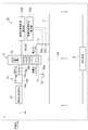
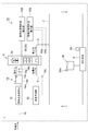
- FIG. 2 is a schematic view corresponding to the circulating water utilization system shown in FIG. 1, and particularly shows an arrangement example of treatment tanks in the purifying means and the drinking water generating means. It is the whole schematic diagram which showed the circulating water utilization system concerning at least 1 embodiment of this invention. It is a schematic diagram corresponding to the circulating water utilization system shown in FIG. 10, Comprising: Especially the example of arrangement
- FIG. 10 is a schematic view corresponding to the circulating water utilization system shown in FIG. 1, and particularly shows an arrangement example of treatment tanks in the purifying means and the drinking water generating means. It is the whole schematic diagram which showed the circulating water utilization system concerning at least 1 embodiment of this invention. It is a schematic diagram corresponding to the circulating water utilization system shown in FIG. 10, Comprising: Especially the example of arrangement
- FIG. 13 is a schematic diagram corresponding to the circulating water utilization system shown in FIG. 12, and particularly shows an arrangement example of treatment tanks in the purifying means and the drinking water generating means. It is the whole schematic diagram which showed the circulating water utilization system concerning at least 1 embodiment of this invention. It is the whole schematic diagram which showed the circulating water utilization system concerning at least 1 embodiment of this invention.
- FIG. 16 is a schematic diagram corresponding to the circulating water utilization system shown in FIG. 15, and particularly shows an arrangement example of treatment tanks in the purifying means and the drinking water generating means.
- FIG. 1 is an overall schematic diagram showing a circulating water utilization system according to at least one embodiment of the present invention.
- the circulating water utilization system 1 is a system constructed for a specific area separately from the public water supply network.
- the population scale targeted by this system is assumed to be approximately 5,000 to 20,000.
- the target area includes a condominium that is a collection of residences, an office building that is a collection of offices, a commercial facility that is a collection of tenants, and a complex facility in which these are mixed.
- the circulating water utilization system 1 includes a circulating flow path 2, a water demand body 3, a discharge flow path 4, a supply flow path 6, a purification means 8, a charging means 10 (charging apparatus), and potable water generation. Means 12, drinking water supply means 14, and the like.
- the circulation channel 2 is configured as a pipe network in which water pipes are arranged in a closed loop shape.
- Devices such as a pump (not shown) and a valve (not shown) are appropriately arranged in the circulation channel 2 according to the terrain conditions so that the circulating water circulates in one direction.
- the raw water of the circulating water flowing through the circulation channel 2 is not limited to tap water supplied from a public water supply, and may be well water, water taken from a river, water obtained by desalinating seawater, rainwater, or the like. Further, when the circulating water is insufficient, the raw water may be taken into the circulation channel 2 as makeup water from the outside.
- the water consumer 3 is a main body that uses the circulating water flowing through the circulation channel 2 as domestic water.
- the water demanding body 3 is constituted by a plurality of small water demanding bodies consisting of at least one of the residence 3a, the tenant 3b, and the office 3c.
- the dwelling 3a refers to a room in a condominium where one household lives or a detached house.
- the tenant 3b refers to a store that provides services to general customers in a section of a commercial facility.
- the business types include, for example, retail stores such as clothing stores, general stores, drug stores, liquor stores, and restaurants, restaurants, cafes, sushi restaurants, taverns, and the like.
- the office 3c refers to a place where a worker who works in a part of an office building performs office work for a certain purpose.
- Examples of the use of domestic water in the residence 3a include showers, baths, washing, washing dishes, washing hands, washing faces, toilets, and the like.
- Examples of the use of domestic water in the tenant 3b include washing and toilets.
- the amount of water demand varies greatly depending on the type of industry. For example, restaurants use a much larger amount of domestic water than retailers.
- the use of domestic water in the office 3c is mainly a toilet.
- drinking water is supplied to the water consumer 3 separately from the circulating water described above.
- This drinking water is generated by further purifying tap water introduced from a public water supply network, and has the same quality as commercially available mineral water.
- Such a mechanism can eliminate the anxiety of those who are reluctant to drink circulating water, and is expected to become a selling point when spreading this circulating water utilization system 1. It is.
- the tap water is led from the public water supply network to the drinking water generating means 12 through the tap water conduit 16.
- the drinking water generating means 12 purifies the introduced tap water and generates drinking water for the water consumer 3.
- the potable water generating means 12 uses a container-type treatment tank in which a processing device that performs one processing step among a series of purification steps is stored in the container, similarly to the purification means 8 described later. And it is comprised by connecting this container type processing tank in series along the order of a process process.
- a container refers to the rectangular container by which the dimension was standardized for the transportation use.
- Drinking water generated by the drinking water generating means 12 is supplied to each of the small-bore water consumer by the drinking water supply means 14.
- the potable water supply means 14 includes a potable water feed pipe 14a, a storage tank 14b, a potable water pipe 14c, and the like.
- the potable water generated by the potable water generating means 12 is sent to the storage tank 14b via the potable water supply pipe 14a and temporarily stored in the storage tank 14b.
- the drinking water currently stored by the storage tank 14b is supplied to each of the small-lot water demand body which consists of the residence 3a mentioned above, the tenant 3b, and the office 3c via the drinking water piping 14c.
- the discharge flow path 4 is a flow path for draining the discharged water discharged from the water consumer 3 to the circulation flow path 2.
- the discharged water discharged from the discharge flow path 4 includes potable water and other water derived from outside the system in addition to the circulating water used by the water consumer 3 as domestic water.
- the supply flow path 6 is a flow path for supplying the circulating water purified by the purification means 8 described later to the water consumer 3 as domestic water. Both the discharge flow path 4 and the supply flow path 6 are constituted by pipe lines. Further, the discharge channel 4 and the supply channel 6 are appropriately set according to the terrain conditions so that the discharged water is drained into the circulation channel 2 or the circulating water is supplied to the water demanding body 3. Devices such as a pump (not shown) and a valve (not shown) are arranged.
- the purification means 8 is a means for purifying the circulating water including the discharged water flowing through the circulation flow path 2.
- the purification means 8 uses a container-type treatment tank in which a treatment apparatus that performs one treatment step among a series of purification steps is stored inside the container. And it is comprised by connecting this container type processing tank in series along the order of a process process.
- the circulation channel 2 is not connected to a public sewer network.
- surplus sludge such as sludge cake generated in the purification process of discharged water is carried out of the system, but other discharged water is reused 100%. That is, the present circulating water utilization system 1 is a completely circulating circulating water utilization system in which water supply and water treatment are performed cyclically in the system, and sewage is not discharged outside the system.
- the billing means 10 is a means for calculating the circulating water usage fee in each of the above-mentioned small-lot water demanding bodies.
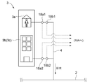
- the charging unit 10 includes at least a discharge water amount measuring unit 18a, a water quality measuring unit 18b, and a circulating water usage charge calculating unit 10A.
- the discharged water amount measuring means 18a includes a flow meter for measuring the discharged water amount and weight discharged from the water demanding body 3 provided in the discharge flow path 4 described above.
- the water quality measuring means 18b is provided in the discharge flow path 4 described above, and SS (suspended substance amount), BOD (biological oxygen demand), TOC (total organic matter) discharged from the water consumer 3 Various water qualities that measure water quality indicators such as carbon), COD (chemical oxygen demand), TN (total nitrogen), TP (total phosphorus), normal hexane extract, and other fungi such as Escherichia coli It consists of sensors.
- the water quality measuring means 18b may be constituted by a portable water quality test kit, a microfluidic device, or the like, instead of these stationary water quality sensors.
- the water quality measuring unit 18b may be configured to continuously measure the water quality index, or may be configured to periodically measure the water quality index.
- the discharged water amount measuring means 18a includes a plurality of flow meters 18a1 so as to measure the discharged water amount discharged from each of the small water demanding bodies such as the residence 3a, the tenant 3b, and the office 3c. , 18a2.
- the water quality measuring means 18b also includes a plurality of water qualities so as to measure the quality of the discharged water discharged from each of the small-lot water demanding bodies such as the residence 3a, the tenant 3b, and the office 3c. It consists of water quality sensors 18b1 and 18b2.
- the circulating water usage charge calculation unit 10A and the potable water usage charge calculation unit 10B which will be described later, include a central processing unit (CPU), a random access memory (RAM), a read-only memory (ROM), and an I / O interface. It is configured as a computer. And the circulating water usage charge calculation part 10A is comprised so that each circulating water usage charge of a small-lot water demand body may be calculated according to the calculation logic shown in FIG. 2, and the calculation flow shown in FIG.
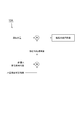
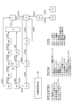
- FIG. 2 is a diagram showing the calculation logic of the circulating water usage fee in the circulating water usage fee calculation unit.
- the circulating water usage charge calculation unit 10A circulates by multiplying the amount of discharged water discharged from each of the small-bore water demand measured by the discharged water amount measuring means 18a by the waste water treatment unit price. Configured to calculate water usage charges.
- the discharged water treatment unit price is calculated by multiplying the circulating water unit usage fee by a water quality unit price correction coefficient set based on a water quality index related to the water quality of the discharged water measured by the water quality measuring means 18b.
- FIG. 3 is a diagram showing a calculation flow of the circulating water usage fee in the billing apparatus.
- the discharged water amount measuring means 18a described above measures the discharged water amount discharged from each of the small-lot water demanding bodies (S31).
- a water quality index relating to the quality of the discharged water discharged from each of the small-bore water demanding bodies is measured by the water quality measuring means 18b described above (S32). Note that the order of step S31 and step S32 may be reversed, or may be executed simultaneously.
- step S33 a wastewater treatment unit price is calculated.
- the unit cost of wastewater treatment is calculated by multiplying the circulating water unit charge by the water quality unit price correction factor.
- the circulating water unit usage fee is set as, for example, a uniform fee according to, for example, each circulating water utilization system, each industry, and each contract size.
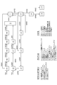
- the water quality unit price correction coefficient is a correction coefficient set according to the water quality of the discharged water, and is set as shown in FIG. 5, for example.
- Fig. 5 is a table showing a calculation example of the water quality unit price correction coefficient.
- the water quality unit price correction coefficient is calculated from four water quality indicators such as SS (suspended substance amount), normal hexane extract substance (oil content), BOD, TOC, COD etc. (organic substance), and TP (total phosphorus). The example which calculates is shown.
- a weighting coefficient is defined in advance for each of a plurality of water quality indicators.
- a method for setting the weighting coefficient for example, it is conceivable to set the weighting coefficient in accordance with the proportion of the purification cost.
- the weighting coefficients of the plurality of water quality indicators are set so that the sum of them is 1.
- a standard value is defined in advance for each of a plurality of water quality indicators.
- This reference value is a value that serves as a reference for calculating the circulating water usage fee, and is set as, for example, a standard processing capability in the purification means 8. Further, for example, the reference value can be made variable according to the contract form.
- the pollution coefficient is an index for evaluating the degree of pollution in each water quality index, and is defined as the ratio of the measured value of the water quality index to the above reference value.
- the actual measured value of the water quality index the measured value of the water quality index measured by the water quality measuring means 18b described above is used.
- the actual measurement value for example, an average value within a certain period is used.
- index is calculated by multiplying the weighting coefficient mentioned above to this pollution coefficient.
- the water quality unit price correction coefficient is calculated by summing up the water quality unit price correction values in the plurality of water quality indexes.
- the amount of pollutant components that need to be treated in the water quality index having a high weighting coefficient is larger than the reference value, so that 1. 55 times.
- the circulating water usage fee is calculated by multiplying the discharged water amount by the calculated wastewater treatment unit price (S34). Finally, the calculated circulating water usage fee is charged for each of the small-lot water demanding bodies (S35).
- the charging device 10 of the circulating water utilization system 1 since charging is performed based on the discharged water, it cannot be grasped when measuring only the supply amount.
- the discharged water can also be grasped, and a more fair charging system can be constructed.
- a weighting coefficient in advance for each of a plurality of water quality indices for example, a high weighting coefficient is set for a water quality index having a high proportion of the purification cost among the plurality of water quality indices.
- the circulating water utilization system 1 further includes potable water generating means 12 that purifies the tap water introduced from the water supply network and generates potable water for the water consumer 3 as described above. .
- Drinking water generated by the drinking water generating means 12 is supplied to each of the small-bore water consumer by the drinking water supply means 14.
- the potable water supply means 14 includes a potable water feed pipe 14a, a storage tank 14b, a potable water pipe 14c, and the like.
- the potable water generated by the potable water generating means 12 is sent to the storage tank 14b via the potable water supply pipe 14a and temporarily stored in the storage tank 14b.
- the drinking water currently stored by the storage tank 14b is supplied to each of the small-lot water demand body which consists of the residence 3a mentioned above, the tenant 3b, and the office 3c via the drinking water piping 14c.
- the billing device 10 described above relates to drinking water amount measuring means 19a for measuring the amount of drinking water supplied to each of the small-bore water consumers, and the drinking water quality supplied to each of the small-bore water consumers. Based on the drinking water quality measuring means 19b for measuring the drinking water quality index and the drinking water quantity and the drinking water quality supplied to each of the small water consumers, the drinking water usage fee of each of the small water consumers is calculated. And a drinking water usage fee calculation unit 10B.
- the drinking water amount measuring means 19a measures the amount of drinking water supplied to each of the small-bore water consumers such as the dwelling 3a, the tenant 3b, and the office 3c. It consists of a plurality of flow meters 19a1 and 19a2 provided on the pipes 14c1 and 14c2, respectively.
- the drinking water quality measuring means 19b is provided in the drinking water pipe 14c before branching directly downstream of the storage tank 14b so that the drinking water quality supplied to each of the small-bore water consumers can be collectively measured. It consists of a water quality sensor 19b.
- the drinking water quality index measured by the water quality sensor 19b is not particularly limited.
- the drinking water quality measuring means 19b may be constituted by a portable water quality test kit, a microfluidic device, or the like, instead of the stationary water quality sensor. Further, the drinking water quality measuring means 19b may be configured to continuously measure the water quality index, or may be configured to periodically measure the water quality index.
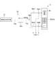
- FIG. 6 is a diagram showing the drinking water usage charge calculation logic in the drinking water usage charge calculation unit.
- the drinking water usage fee calculation unit 10B multiplies the drinking water amount supplied to each of the small-bore water demanding bodies measured by the drinking water volume measuring means 19a by the drinking water unit price, It is configured to calculate a potable water usage fee.
- the potable water unit price is calculated by multiplying the potable water unit usage fee by a potable water unit price correction coefficient set based on a water quality index related to the potable water quality measured by the potable water quality measuring means 19b.
- FIG. 7 is a diagram showing a calculation flow of the potable water usage fee in the billing apparatus.
- the drinking water volume measuring means 19a described above measures the drinking water volume supplied to each of the small-bore water consumers (S71).
- the water quality indicator relating to the quality of the drinking water supplied to the small-bore water consumer is measured by the drinking water quality measuring means 19b described above (S72). Note that the order of these steps S71 and S72 may be reversed or may be executed simultaneously.
- step S73 the drinking water unit price is calculated.
- Drinking water unit price is calculated by multiplying the potable water unit charge by the potable water unit price correction factor.
- the potable water unit usage fee is set as, for example, a uniform fee according to, for example, each circulating water utilization system, each industry, and each contract size.
- the drinking water unit price correction coefficient is a correction coefficient set according to the quality of the drinking water supplied, and the drinking water unit price correction coefficient is set higher as the quality of the drinking water is higher.
- the potable water unit price correction coefficient is set higher as the odor intensity (TON), which is an index representing the odor intensity, is lower.
- TON odor intensity
- concentration is low.
- TOC organic matter
- the drinking water usage fee is calculated by multiplying the drinking water amount by the calculated drinking water unit price (S74). Finally, the calculated drinking water usage fee is charged for each of the small-bore water consumers (S75).
- the potable water usage fee supplied to each of the small-bore water consumers is calculated based on the drinking water quality as well as the amount of drinking water supplied. Can be done.
- the raw water of the drinking water in the circulating water utilization system 1 is not limited to tap water,
- the water taken from the well water, the river, the water which desalinated seawater, etc. may be sufficient.
- FIG. 9 is a schematic diagram corresponding to the circulating water utilization system shown in FIG. 1, and particularly shows an arrangement example of treatment tanks in the purification means and the drinking water generating means.
- the purification means 8 includes a screen / flow rate adjusting container L1, an anaerobic container L2, an aerobic container L3, a coarse film container L4, a fine film container L5, an ozone treatment container L6, and a water storage sterilization container L7.
- the sterilization container L8 is configured by being connected in series in this order.
- the screen / flow rate adjusting container L1 is a processing tank that removes inspection and oil contained in the discharged water, and includes equipment such as an oil trap and a screen device.
- the anaerobic container L2 and the aerobic container L3 are treatment tanks for performing anaerobic treatment and aerobic treatment to remove organic substances contained in the discharged water.
- As the treatment method various known treatment methods such as A20 activated sludge method, batch activated sludge method, contact oxidation method, oxidation ditch method and the like can be adopted.
- the coarse film container L4 is a treatment tank for separating sludge from the discharged water.
- Various apparatuses and methods such as a precipitation tank, MF membrane, UF membrane, and centrifugal separation can be employed.
- the fine membrane container L5 is a treatment tank for increasing the quality of the circulating water to the level of water supply.
- Various devices and methods such as reverse osmosis membrane, activated carbon, sand filtration, ozone generator, ion exchange, and mineral addition device can be employed.
- the ozone treatment container L6 is a treatment tank for performing ozone treatment on the purified circulating water.
- the water storage sterilization container L7 is a treatment tank for temporarily storing the purified circulating water while storing and sterilizing the water with ultraviolet rays.
- the sterilization container L8 is a treatment tank for sterilizing and purifying the purified circulating water with ultraviolet rays, chlorine, ozone, or the like.
- the sludge return / sludge dewatering container L9 is a treatment tank for dewatering and drying the sludge.
- the sludge storage containers L10 and L11 are treatment tanks for storing wastes generated in the sewage treatment such as sludge cakes and grinds. . Excess sludge such as sludge cake stored in the sludge storage containers L10 and L11 is taken out of the system, for example, by being collected by a fertilizer supplier.
- generation means 12 has the fine membrane container H1, the ion exchange container H2, the water storage sterilization container H3, the mineral adjustment container H4, and the disinfection container H5 connected in series in this order. Is made up of.
- the fine membrane container H1, the ion exchange container H2, the water storage sterilization container H3, the mineral adjustment container H4, and the disinfection container H5 are treatment tanks for further purifying the tap water to the same quality as commercially available mineral water. .
- the fine membrane container H1 is equipped with various devices and methods such as reverse osmosis membrane, activated carbon and sand filtration.
- the ion exchange container H2 includes an ion exchange device and the like.
- the water storage sterilization container H3 is a treatment tank for temporarily storing purified tap water while storing and sterilizing the water with ultraviolet rays.
- the mineral adjustment container L4 includes a mineral addition device and the like.
- the sterilization container H5 is a treatment tank for sterilizing and purifying purified tap water with ultraviolet rays, chlorine, ozone, and the like.
- symbol TW in a figure has shown the flow of the tap water supplied from a public water supply network.
- the tap water TW may be configured not only to be supplied to the drinking water generating means 12 as described above, but also to be supplied to the circulation channel 2 as make-up water as necessary.
- the supply position in this case is preferably on the downstream side of the fine membrane container L5 where the purification process of the discharged water is almost completed.
- symbol WW4 in a figure is a return pipeline for sending concentrated water to the screen / flow control container L1.
- a series of purification steps for example, 3
- a container-type processing tank is used in which a processing apparatus that performs one processing step among the plurality of processing steps described above is stored inside a container. Then, a container-type processing tank that performs the first processing step, a container-type processing tank that performs the next processing step, and a container-type processing tank that performs the subsequent processing steps are brought into the field, and each is connected in series with a connecting pipe.
- the purifying means 8 is constructed by connecting to.
- Such a container-type treatment tank is excellent in portability because it can be loaded and transported on a truck as it is. Moreover, since it is detachably accommodated in the container container, it can be installed and removed freely.
- the processing capacity per one processing tank of the container type processing tank is assumed to be a scale capable of processing about 1,000 people of discharged water. For this reason, for example, when this circulating water utilization system is introduced to an area or complex facility where 10,000 people live, a plurality of (for example, 10) treatment tanks that perform the same treatment process are required. Become. Thus, by providing a plurality of processing tanks that perform the same processing step, the processing capacity per processing tank can be reduced. Therefore, it is possible to flexibly cope with population fluctuations and water demand seasonal fluctuations in the target area. Moreover, it is easy to prepare an alternative processing tank, and the maintenance is excellent.
- FIG. 10 is an overall schematic diagram showing a circulating water utilization system according to at least one embodiment of the present invention.
- circulating water monitoring means 32 that monitors the quality of domestic water flowing through the supply flow path 6, and the monitoring result in the circulating water monitoring means 32 is sent to the water consumer 3.
- a notification means 32a for informing the user.
- the circulating water monitoring means 32 can be configured as an automatic water quality monitoring device that automatically measures the chromaticity, turbidity, residual chlorine, pH, conductivity, water temperature, etc. of the circulating water, for example, every predetermined time.
- the tap water monitoring means 28 may be constituted by a portable water quality inspection kit, a microfluidic device or the like instead of the stationary water quality monitoring device.
- the notification means 32a there is a configuration in which data relating to the measurement result measured by the automatic water quality monitoring device is transmitted and displayed on a monitor or the like disposed near the small water demanding body. According to such embodiment, the reliability from the water demand body 3 with respect to the purification
- FIG. 11 is a schematic diagram corresponding to the circulating water utilization system shown in FIG. 10, and particularly shows an arrangement example of treatment tanks in the purifying means and the drinking water generating means.
- two of the treatment tanks L1 to L8 constituting the purification means 8 have sludge separation having a microfiltration membrane for filtering sludge contained in the discharged water.
- the water treatment body 3 is composed of a treatment tank and an advanced treatment tank for performing a subsequent treatment process of the treatment process performed in the sludge separation treatment tank, and filtering the discharged water.
- a middle water supply path 34 is further provided as middle water.
- the sludge separation treatment tank having a microfiltration membrane for filtering sludge contained in the discharged water corresponds to the coarse film container L4 in the plurality of treatment tanks constituting the purification means 8 described above.
- the advanced treatment tank for filtering the discharged water corresponds to the fine membrane container L5 in the plurality of treatment tanks constituting the purification means 8 described above.
- the living water that is supplied to the water demanding body 3 does not come into contact with human skin, for example, is used for toilet flushing water, etc. It is conceivable that the ratio of water used is high. Therefore, according to such an embodiment, by supplying circulating water purified to a level usable as washing water by the sludge separation treatment tank to the water demanding body 3 as intermediate water, the energy required for the subsequent purification process Cost can be reduced.
- a treatment tank monitoring means 36 for remotely monitoring the operation rate of the treatment tanks constituting the purification means 8 and the drinking water generation means 12 described above is further provided.
- Each of the treatment tanks constituting the purification means 8 and the drinking water generation means 12 is provided with an operation rate sensor for detecting the operation rate of the treatment tank. And the information regarding the operating rate of each processing tank detected by the operating rate sensor is transmitted to the processing tank monitoring unit 36 located away from the purification unit 8 by wire or wireless. The transmitted information regarding the operating rate of each processing tank is displayed on the display unit of the processing tank monitoring means 36. An operator who supervises the circulating water utilization system 1 monitors the operation rate of each treatment tank displayed on the treatment tank monitoring means 36. According to such an embodiment, it is possible to quickly and easily determine whether to add or remove a treatment tank by remotely monitoring the operating rate of the treatment tanks constituting the purification means 8 and the drinking water generation means 12. .
- the abnormality detection sensor which detects the abnormality of the processing tank may be attached to the processing tank which comprises the purification
- FIG. 12 is an overall schematic diagram showing a circulating water utilization system according to at least one embodiment of the present invention.
- FIG. 13 is a schematic diagram corresponding to the circulating water utilization system shown in FIG. 12, and particularly shows an arrangement example of treatment tanks in the purifying means and the drinking water generating means.
- the circulating flow path 2 and the drinking water generating means 12 are connected, and the circulating water purified by the purifying means 8 is supplied to the drinking water generating means 12.
- the apparatus further includes a purified water supply pipe 22 and a water control valve 24 for opening and closing the purified water supply pipe 22.
- the water control valve 24 is normally closed, and the circulating water is not supplied to the drinking water generating means 12, but the water control valve 24 is opened when the supply of tap water from the water supply network is stopped.
- circulating water is supplied to the drinking water generating means 12 through the purified water supply pipe 22.
- a water cutoff detection unit 26 that can detect water cutoff in the water supply network, and a water control valve control unit 24a that controls opening and closing of the water control valve 24 are further provided.
- the water control valve control unit 24a is configured to open the water control valve 24 when the water stop detection means 26 detects water supply in the water supply network.
- water outage information transmitted from the Waterworks Bureau or the like can be used.
- the water control valve control unit 24a opens the water control valve 24, and the drinking water generating means 12 is supplied from the purified water supply pipe 22. Purified circulating water is supplied. For this reason, even when the water supply network is shut down, the drinking water generating means 12 can be continuously supplied with water.
- FIG. 14 is an overall schematic view showing a circulating water utilization system according to at least one embodiment of the present invention.
- tap water monitoring means 28 for monitoring the quality of tap water
- tap water shut-off valve 30 capable of shutting off tap water, and opening / closing of water control valve 24.
- a tap water shut-off valve control unit 30a for controlling the operation of the tap water shut-off valve 30.
- the tap water monitoring means 28 detects that the quality of the tap water is worse than the prescribed water quality
- the water control valve control unit 24a opens the water control valve 24 that is normally closed. Control.
- the tap water shut-off valve control unit 30a operates the tap water shut-off valve 30 that is normally open to shut off the tap water.
- the tap water monitoring means 28 As an example of the tap water monitoring means 28, as with the circulating water monitoring means 32 described above, the chromaticity, turbidity, residual chlorine, pH, conductivity, water temperature, etc. of tap water are automatically measured at predetermined intervals, for example. It can be configured as an automatic water quality monitoring device.
- the tap water monitoring means 28 may be constituted by a portable water quality inspection kit, a microfluidic device or the like instead of the stationary water quality monitoring device. According to such an embodiment, when the tap water monitoring means 28 detects that the quality of the tap water is worse than the prescribed water quality, the tap water cutoff valve control unit 30a operates the tap water cutoff valve 30.
- the water control valve 24 a opens the water control valve 24 while shutting off the tap water, and the purified circulating water is supplied from the purified water supply pipe 22 to the drinking water generating means 12. For this reason, even when the quality of tap water deteriorates, the drinking water generating means 12 can be continuously supplied with water.
- FIG. 15 is an overall schematic diagram showing a circulating water utilization system according to at least one embodiment of the present invention.
- FIG. 16 is a schematic diagram corresponding to the circulating water utilization system shown in FIG. 15, and particularly shows an arrangement example of treatment tanks in the purifying means and the drinking water generating means.
- the circulating water storage tank 38 that stores the circulating water purified by the purification means 8 and the amount of circulating water stored in the circulating water storage tank 38 are stored.
- a storage amount measuring means 38a for measuring and a purifying means control unit 8a for controlling the driving of the purifying means 8 are further provided.
- the circulating water storage tank 38 may be provided separately from the purification means 8, or the above-described water storage sterilization container L 7 may be used as the circulating water storage tank 38 as shown in FIG.
- a water level meter that measures the water level of the circulating water storage tank 38 may be used.
- the purifying means control unit 8a controls the supply of circulating water sent to the purifying means 8 by controlling pumps and valves, for example, and drives the devices of various processing tanks constituting the purifying means 8. By controlling, the drive of the whole purification means 8 is controlled.
- the purification cost can be reduced by preferentially driving the purification means 8 in a time zone such as at night when the power charge is always low. Moreover, when the storage amount of the circulating water storage tank 38 measured by the storage amount measurement means 38a is less than the prescribed storage amount, the purification means 8 is driven regardless of the time zone to supply to the water demanding body 3. It is possible to avoid the situation where water for daily life is insufficient.
- the domestic water amount measuring means 18 c that measures the amount of domestic water supplied from the supply flow path 6 to the water consumer 3 and the demand prediction of the domestic water amount are performed.
- a demand prediction unit 39 is configured as a microcomputer including a central processing unit (CPU), a random access memory (RAM), a read only memory (ROM), and an I / O interface.
- the domestic water volume measuring means 18c includes, for example, a flow meter 18c. Then, the daily water amount measured by the domestic water amount measuring unit 18c is memorized every moment, and the future water demand for domestic water is predicted based on the stored past daily water amount. Has been.
- the amount of domestic water supplied in the same month, day, day of the week, time zone, etc. in the past can be used as a predicted value of water demand.
- the predicted value of water demand can also be corrected based on outside air information such as temperature and humidity. According to such an embodiment, since the purification means 8 can be appropriately driven according to the prediction result of the water demand, the purification means 8 can be operated efficiently.
- At least one embodiment of the present invention can be suitably used in a circulating water utilization system constructed for a specific area separately from a public water supply network.
Landscapes
- Engineering & Computer Science (AREA)
- Water Supply & Treatment (AREA)
- Life Sciences & Earth Sciences (AREA)
- Chemical & Material Sciences (AREA)
- Hydrology & Water Resources (AREA)
- Environmental & Geological Engineering (AREA)
- Organic Chemistry (AREA)
- Business, Economics & Management (AREA)
- Health & Medical Sciences (AREA)
- Economics (AREA)
- Strategic Management (AREA)
- Public Health (AREA)
- Marketing (AREA)
- Physics & Mathematics (AREA)
- General Business, Economics & Management (AREA)
- General Physics & Mathematics (AREA)
- Theoretical Computer Science (AREA)
- Human Resources & Organizations (AREA)
- Finance (AREA)
- Accounting & Taxation (AREA)
- Development Economics (AREA)
- Tourism & Hospitality (AREA)
- Entrepreneurship & Innovation (AREA)
- Analytical Chemistry (AREA)
- Microbiology (AREA)
- Toxicology (AREA)
- Medicinal Chemistry (AREA)
- Mechanical Engineering (AREA)
- Technology Law (AREA)
- Biodiversity & Conservation Biology (AREA)
- General Health & Medical Sciences (AREA)
- Primary Health Care (AREA)
- Educational Administration (AREA)
- Game Theory and Decision Science (AREA)
- Operations Research (AREA)
- Quality & Reliability (AREA)
- Management, Administration, Business Operations System, And Electronic Commerce (AREA)
- Separation Using Semi-Permeable Membranes (AREA)
- Indication And Recording Devices For Special Purposes And Tariff Metering Devices (AREA)
- Beverage Vending Machines With Cups, And Gas Or Electricity Vending Machines (AREA)
Abstract
Description
上述した従来の再利用システムは、基本的に一建物内や一家庭等内において、上水道網から供給される上水の排水を浄化して特定用途の中水として利用するものであり、利用後の中水は下水道網に排出される。すなわち、既存の公共の上水道網、下水道網の存在が前提であり、これに代替するシステムとはなり得ない。
特定の地域を対象として構築される循環水利用システムの課金装置であって、
前記循環水利用システムは、
循環水が流れる循環流路と、
前記循環流路を流れる循環水を使用する、住居、テナント、及び事務所の内の少なくとも一種からなる小口水需要体が複数集まって構成される水需要体、から排出される排出水を前記循環流路へ排出する排出流路と、
前記循環流路を流れる前記排出水を含む循環水を浄化する浄化手段と、
前記浄化手段で浄化された循環水を前記水需要体に供給する供給流路と、
前記小口水需要体の各々における循環水使用料金を算出する課金装置と、を少なくとも含み、
前記課金装置は、
前記小口水需要体の各々から排出される排出水量を夫々計測する排出水量計測手段と、
前記小口水需要体の各々から排出される排出水の水質に関する水質指標を夫々測定する水質測定手段と、
前記小口水需要体の各々から排出される排出水量及び排出水の水質に基づいて、前記小口水需要体の各々の循環水使用料金を算出する循環水使用料金算出部と、を備える。
これに対して上記循環水利用システムの課金装置は、これまでの公共の上下水道網とは異なり、小口水需要体の各々から排出される排出水量及び排出水の水質に基づいて、小口水需要体の各々の循環水使用料金を算出するものである。
ただし、本発明の範囲は以下の実施形態に限定されるものではない。以下の実施形態に記載されている構成部品の寸法、材質、形状、その相対配置などは、本発明の範囲をそれにのみ限定する趣旨ではなく、単なる説明例に過ぎない。
循環水利用システム1は、公共の上水道網とは別に、特定の地域を対象として構築されるシステムである。本システムの対象となる人口規模としては、おおよそ5,000~20,000人を想定している。対象地域としては、住居の集合体であるマンション、事務所の集合体であるオフィスビル、テナントの集合体である商業施設、及びこれらが混在する複合施設などである。
循環流路2を流れる循環水の原水は、公共の上水道から供給される水道水に限定されず、井戸水、河川から取水した水、海水を淡水化した水、雨水等であってもよい。また、循環水が不足する場合には、これらの原水を外部から補給水として循環流路2に取り入れるように構成してもよい。なお、これらの原水を補給水として循環流路2に取り入れる場合、その水質レベルに応じて後述する浄化手段8の処理槽に取り込むとよい。例えば、比較的水質の良い井戸水、河川から取水した水、海水を淡水化した水については、後述する浄化手段8の粗膜コンテナL4又は微細膜コンテナL5に取り込み、比較的水質の悪い雨水については通気性コンテナL2、好気性コンテナL3に取り込むように構成するとよい。
住居3aにおける生活用水の用途としては、例えばシャワーや風呂、洗濯、食器の洗浄、手洗いや洗顔、トイレ、等々が挙げられる。テナント3bにおける生活用水の用途としては、洗浄やトイレ等が挙げられる。また業種によって水需要量が大きく異なっており、例えば飲食店は小売業と比べてはるかに大量の生活用水を利用する。事務所3cにおける生活用水の用途は主にトイレである。
なお、本明細書においてコンテナとは、輸送用途のため寸法が規格化された矩形状の容器のことを指す。
課金手段10は、図1に示すように、排出水量計測手段18a、水質測定手段18b、及び循環水使用料金算出部10Aを少なくとも備えている。
幾つかの実施形態では、図10に示したように、供給流路6を流れる生活用水の水質を監視する循環水監視手段32と、該循環水監視手段32における監視結果を水需要体3に対して報知する報知手段32aと、をさらに備える。
報知手段32aとしては、自動水質監視装置で測定された測定結果に関するデータを送信し、小口水需要体の近くに配置されたモニターなどに表示する構成が挙げられる。
このような実施形態によれば、供給される生活用水の水質を水需要体に対して報知することで、本循環水利用システム1の浄化手段8に対する水需要体3からの信頼を高めることができる。
幾つかの実施形態では、図11に示したように、浄化手段8を構成する処理槽L1~L8の内の2つは、排出水に含まれる汚泥をろ過処理する精密ろ過膜を有する汚泥分離処理槽、及び該汚泥分離処理槽で行われる処理工程の次処理工程を行う、排出水をろ過処理する高度処理槽、からなり、汚泥分離処理槽から排出される被処理水を水需要体3に中水として供給する中水供給路34をさらに備える。
このような実施形態によれば、浄化手段8および飲用水生成手段12を構成する処理槽の稼働率を遠隔監視することで、処理槽の増設及び撤去の判断を迅速かつ容易に行うことが出来る。
このような実施形態によれば、浄化手段8および飲用水生成手段12を構成する処理槽の異常を遠隔監視することで、処理槽のメンテナンスを迅速に行うことが出来る。
このような実施形態によれば、断水検知手段26が上水道網の断水が検知した時には、制水弁制御ユニット24aが制水弁24を開弁し、浄化水供給管22から飲用水生成手段12に浄化された循環水が供給される。このため、上水道網の断水時でも、飲用水生成手段12に対して継続的に給水を行うことが出来るようになっている。
幾つかの実施形態では、図14に示したように、水道水の水質を監視する水道水監視手段28と、水道水の導水を遮断可能な水道水遮断弁30と、制水弁24の開閉を制御する制水弁制御ユニット24aと、水道水遮断弁30の作動を制御する水道水遮断弁制御ユニット30aと、をさらに備える。そして、水道水監視手段28が水道水の水質が規定の水質よりも悪化したことを検知すると、制水弁制御ユニット24aが、常時は閉弁している制水弁24を開弁するように制御する。また、水道水遮断弁制御ユニット30aが、常時は開弁している水道水遮断弁30を作動させて水道水の導水を遮断する。
このような実施形態によれば、水道水監視手段28が水道水の水質が規定の水質よりも悪化したことを検知した時には、水道水遮断弁制御ユニット30aが水道水遮断弁30を作動させて水道水の導水を遮断するとともに、制水弁制御ユニット24aが制水弁24を開弁し、浄化水供給管22から飲用水生成手段12に浄化された循環水が供給される。このため、水道水の水質悪化時にも、飲用水生成手段12に対して継続的に給水を行うことが出来るようになっている。
幾つかの実施形態では、図15に示したように、浄化手段8で浄化された循環水を貯留する循環水貯留タンク38と、循環水貯留タンク38に貯留されている循環水の貯留量を計測する貯留量計測手段38aと、浄化手段8の駆動を制御する浄化手段制御ユニット8aと、をさらに備えている。
需要予測部39は、中央処理装置(CPU)、ランダムアクセスメモリ(RAM)、リードオンリメモリ(ROM)、およびI/Oインターフェイスなどからなるマイクロコンピュータとして構成されている。生活用水量計測手段18cは、例えば流量計18cなどからなる。そして、生活用水量計測手段18cで計測された生活用水量を時々刻々と記憶するとともに、該記憶している過去の生活用水量に基づいて、将来の生活用水の水需要を予測するように構成されている。
このような実施形態によれば、水需要の予測結果に応じて適宜浄化手段8を駆動させることが出来るため、浄化手段8を効率的に運用することが出来る。
2 循環流路
3 水需要体
3a 住居
3b テナント
3c 事務所
4 排出流路
6 供給流路
8 浄化手段
8a 浄化手段制御ユニット
10 課金手段(課金装置)
10A 循環水使用料金算出部
10B 飲用水使用料金算出部
12 飲用水生成手段
14 飲用水供給手段
14a 飲用水送水管
14b 貯留タンク、飲用水タンク
14c 飲用水配管
16 水道水導水管
18a 排出水量計測手段(流量計)
18b 水質測定手段(水質センサ)
18c 生活用水量計測手段(流量計)
19a 飲用水量計測手段(流量計)
19b 飲用水質測定手段(水質センサ)
22 浄化水供給管
24 制水弁
24a 制水弁制御ユニット
26 断水検知手段
28 水道水監視手段
30 水道水遮断弁
30a 水道水遮断弁制御ユニット
32 循環水監視手段
32a 報知手段
34 中水供給路
36 処理槽監視手段
38 循環水貯留タンク
38a 貯留量計測手段
39 需要予測部
Claims (7)
- 循環水利用システムの課金装置であって、
前記循環水利用システムは、
循環水が流れる循環流路と、
前記循環流路を流れる循環水を使用する、住居、テナント、及び事務所の内の少なくとも一種からなる小口水需要体が複数集まって構成される水需要体、から排出される排出水を前記循環流路へ排出する排出流路と、
前記循環流路を流れる前記排出水を含む循環水を浄化する浄化手段と、
前記浄化手段で浄化された循環水を前記水需要体に供給する供給流路と、
前記小口水需要体の各々における循環水使用料金を算出する課金装置と、を少なくとも含み、
前記課金装置は、
前記小口水需要体の各々から排出される排出水量を夫々計測する排出水量計測手段と、
前記小口水需要体の各々から排出される排出水の水質に関する水質指標を夫々測定する水質測定手段と、
前記小口水需要体の各々から排出される排出水量及び排出水の水質に基づいて、前記小口水需要体の各々の循環水使用料金を算出する循環水使用料金算出部と、を備える
循環水利用システムの課金装置。 - 前記循環水使用料金算出部は、前記排出水量計測手段で計測される前記小口水需要体の各々から排出される排出水量に、前記水質測定手段で測定される前記小口水需要体の各々から排出される排出水の水質に関する水質指標に基づいて設定される排出水処理単価を乗じて前記循環水使用料金を算出するように構成される
請求項1に記載の循環水利用システムの課金装置。 - 前記排出水処理単価は、複数の前記水質指標に基づいて設定される
請求項2に記載の循環水利用システムの課金装置。 - 前記排出水処理単価は、前記複数の水質指標の各々に対して予め規定される重み付け係数を考慮して設定される
請求項3に記載の循環水利用システムの課金装置。 - 前記排出水処理単価は、予め規定される基準値に対する前記水質指標の実測値の比である汚濁係数に、前記重み付け係数を乗じることで算出される水質単価補正係数に応じて設定される
請求項4に記載の循環水利用システムの課金装置。 - 前記循環水利用システムは、
システム外から導水した水を浄化して前記水需要体のための飲用水を生成する飲用水生成手段をさらに備え、
前記課金装置は、
前記小口水需要体の各々に供給される飲用水量を夫々計測する飲用水量計測手段と、
前記小口水需要体の各々に供給される飲用水の飲用水質に関する飲用水質指標を夫々測定する飲用水質測定手段と、
前記小口水需要体の各々に供給される飲用水量及び飲用水の飲用水質に基づいて、前記小口水需要体の各々の飲用水使用料金を算出する飲用水使用料金算出部と、をさらに備える
請求項1に記載の循環水利用システムの課金装置。 - 循環水が流れる循環流路と、
前記循環流路を流れる循環水を使用する、住居、テナント、及び事務所の内の少なくとも一種からなる小口水需要体が複数集まって構成される水需要体、から排出される排出水を前記循環流路へ排出する排出流路と、
前記循環流路を流れる前記排出水を含む循環水を浄化する浄化手段と、
前記浄化手段で浄化された循環水を前記水需要体に供給する供給流路と、
請求項1~6何れか一項に記載の循環水利用システムの課金装置と、を含む
循環水利用システム。
Priority Applications (2)
| Application Number | Priority Date | Filing Date | Title |
|---|---|---|---|
| MX2016006860A MX2016006860A (es) | 2013-12-05 | 2014-12-04 | Dispositivo de cobro de sistema de utilizacion de agua circulante y sistema de utilizacion de agua circulante. |
| US15/100,865 US10997673B2 (en) | 2013-12-05 | 2014-12-04 | Charging device of circulating water utilization system and circulating-water utilization system |
Applications Claiming Priority (2)
| Application Number | Priority Date | Filing Date | Title |
|---|---|---|---|
| JP2013-251620 | 2013-12-05 | ||
| JP2013251620A JP5512032B1 (ja) | 2013-12-05 | 2013-12-05 | 循環水利用システムの課金装置、循環水利用システム |
Publications (1)
| Publication Number | Publication Date |
|---|---|
| WO2015083786A1 true WO2015083786A1 (ja) | 2015-06-11 |
Family
ID=51031145
Family Applications (1)
| Application Number | Title | Priority Date | Filing Date |
|---|---|---|---|
| PCT/JP2014/082098 Ceased WO2015083786A1 (ja) | 2013-12-05 | 2014-12-04 | 循環水利用システムの課金装置、循環水利用システム |
Country Status (4)
| Country | Link |
|---|---|
| US (1) | US10997673B2 (ja) |
| JP (1) | JP5512032B1 (ja) |
| MX (1) | MX2016006860A (ja) |
| WO (1) | WO2015083786A1 (ja) |
Cited By (1)
| Publication number | Priority date | Publication date | Assignee | Title |
|---|---|---|---|---|
| WO2022239050A1 (ja) * | 2021-05-10 | 2022-11-17 | 三菱電機株式会社 | 制御装置、オゾン発生システム、オゾン貯蔵装置、オゾン発生装置、水処理システム、オゾン注入制御方法およびコンピュータプログラム |
Families Citing this family (15)
| Publication number | Priority date | Publication date | Assignee | Title |
|---|---|---|---|---|
| CN104933806A (zh) * | 2015-06-17 | 2015-09-23 | 成都万江港利科技有限公司 | 基于nfc技术的泵站收费系统 |
| WO2017185267A1 (zh) * | 2016-04-27 | 2017-11-02 | 深圳市博恩实业有限公司 | 服务器、通信机柜或空调的散热计费系统 |
| CN106088212A (zh) * | 2016-07-14 | 2016-11-09 | 广州京维智能科技有限公司 | 一种供水管网多层级自动分区方法 |
| US10273165B1 (en) * | 2017-10-12 | 2019-04-30 | Evoqua Water Technologies Llc | Method and apparatus to monitor and control a water system |
| CN108217960B (zh) * | 2018-01-25 | 2021-11-09 | 江苏省农业科学院 | 一种水生态治理方法及其应用 |
| FR3082514A1 (fr) * | 2018-06-18 | 2019-12-20 | Woter Sas | Dispositif de traitement des eaux comportant un tel dispositif |
| WO2020136835A1 (ja) * | 2018-12-27 | 2020-07-02 | 日本電気株式会社 | 浄水注文管理装置、方法及び非一時的なコンピュータ可読媒体 |
| CN110327739B (zh) * | 2019-05-27 | 2021-07-13 | 广州合昕环境科技有限公司 | 城市污染治理与在线监控综合管理平台 |
| US20200378943A1 (en) * | 2019-05-30 | 2020-12-03 | Cambrian Innovation, Inc. | Systems And Methods For Providing Micro-Utility Water And Energy Services |
| CN111562351B (zh) * | 2020-05-28 | 2022-11-22 | 中国大唐集团科学技术研究院有限公司华中电力试验研究院 | 一种反渗透设备进水水质污染指数的自动监测装置及方法 |
| CN111977758B (zh) * | 2020-09-09 | 2024-01-19 | 西安热工研究院有限公司 | 一种间接空冷系统循环水智能净化系统及其使用方法 |
| CN113107048B (zh) * | 2021-03-05 | 2022-05-13 | 深圳市拓安信计控仪表有限公司 | 一种城乡供水一体化下的城乡水质管理方法和系统 |
| JP7703422B2 (ja) * | 2021-10-21 | 2025-07-07 | 住友金属鉱山エンジニアリング株式会社 | 節水成果報酬算出方法及び節水成果報酬算出システム |
| CN117151471B (zh) * | 2023-09-20 | 2024-03-12 | 中国矿业大学(北京) | 一种矿井水处理检测方法及系统 |
| CN117871803B (zh) * | 2023-12-27 | 2025-01-17 | 昊威环保集团有限公司 | 一种废水排放监测系统 |
Citations (3)
| Publication number | Priority date | Publication date | Assignee | Title |
|---|---|---|---|---|
| JPH07251186A (ja) * | 1994-03-17 | 1995-10-03 | Hitachi Ltd | 水処理システム |
| JP2002267657A (ja) * | 2001-03-07 | 2002-09-18 | Sanyo Electric Co Ltd | 排水排出者に対して課金を行なうシステム |
| JP2012106198A (ja) * | 2010-11-18 | 2012-06-07 | Toshiba Corp | 生物学的廃水処理装置 |
Family Cites Families (114)
| Publication number | Priority date | Publication date | Assignee | Title |
|---|---|---|---|---|
| US3638490A (en) * | 1969-01-17 | 1972-02-01 | Carl F Buettner | Fluid flow measuring device |
| US3558255A (en) * | 1970-01-26 | 1971-01-26 | Keene Corp | Control system for waste water treatment plants |
| JPS5116986B1 (ja) | 1970-07-14 | 1976-05-29 | ||
| US4335606A (en) * | 1980-06-13 | 1982-06-22 | Michalak Janusz K | Apparatus and method for measuring fluid |
| JPS61230707A (ja) | 1985-04-06 | 1986-10-15 | Toyota Motor Corp | 限外濾過方法 |
| JPS63119892A (ja) | 1986-11-10 | 1988-05-24 | 株式会社日立ビルシステムサービス | 給水管内部洗浄装置 |
| US5186052A (en) * | 1991-08-07 | 1993-02-16 | Environmental Monitoring And Technologies, Inc. | Storm water flow monitoring |
| JPH0679142A (ja) | 1992-09-07 | 1994-03-22 | Mitsubishi Heavy Ind Ltd | 逆浸透モジュールにおける液の給排方法 |
| JPH06210291A (ja) | 1992-11-20 | 1994-08-02 | Shimizu Corp | 総合水利用システム |
| JPH06226059A (ja) | 1993-01-29 | 1994-08-16 | Kuraray Co Ltd | 濾過装置 |
| JPH06240711A (ja) | 1993-02-19 | 1994-08-30 | Toto Ltd | 中水処理システム |
| JPH06269766A (ja) | 1993-03-17 | 1994-09-27 | Shimizu Corp | 地域排水再利用システム |
| JPH06277455A (ja) | 1993-03-29 | 1994-10-04 | Mitsubishi Heavy Ind Ltd | 限外ろ過膜モジュールの運転方法 |
| US6015496A (en) * | 1993-04-12 | 2000-01-18 | Khudenko; Boris M. | In-sewer treatment of wastewater and sludges |
| JPH0677886U (ja) | 1993-04-14 | 1994-11-01 | 河内板金工業株式会社 | 流水殺菌装置 |
| JP3055359B2 (ja) | 1993-04-20 | 2000-06-26 | 松下電器産業株式会社 | テープカセット情報保護システム |
| JP3270211B2 (ja) | 1993-09-02 | 2002-04-02 | 株式会社竹中工務店 | 淡水製造装置 |
| JPH0819773A (ja) | 1994-07-07 | 1996-01-23 | Onochiyuu:Kk | 排水再利用システム |
| JP3567011B2 (ja) | 1995-02-27 | 2004-09-15 | 株式会社住本科学研究所 | 中水道の循環システム及び貯水槽 |
| JPH09296493A (ja) | 1996-05-03 | 1997-11-18 | Inax Corp | 真空排水システム |
| US5873996A (en) * | 1996-05-03 | 1999-02-23 | Puraq Water Systems, Inc. | Community drinking water purification system |
| JP3579187B2 (ja) | 1996-07-29 | 2004-10-20 | 旭化成ケミカルズ株式会社 | 濾過装置 |
| JPH1057941A (ja) | 1996-08-21 | 1998-03-03 | Inax Corp | 排水再利用装置 |
| US5817231A (en) * | 1996-12-20 | 1998-10-06 | American Dryer Corporation | Water purifying and vending apparatus |
| JPH10286033A (ja) | 1997-04-15 | 1998-10-27 | Shimizu Corp | 中水利用の建物内緑化設備 |
| US5958240A (en) * | 1997-05-19 | 1999-09-28 | Hoel; Timothy L. | System for recycling waste water |
| JPH1190464A (ja) | 1997-09-24 | 1999-04-06 | Toto Ltd | 排水再利用装置 |
| JP3381834B2 (ja) | 1997-10-20 | 2003-03-04 | 栗田工業株式会社 | 排水の再利用方法 |
| JPH11207155A (ja) | 1998-01-27 | 1999-08-03 | Kurita Water Ind Ltd | 海水等の淡水化装置 |
| JPH11220155A (ja) | 1998-02-02 | 1999-08-10 | Tokuzo Hirose | 発電装置 |
| US6463956B2 (en) * | 1998-09-29 | 2002-10-15 | International Water-Guard Industries Inc. | Method of water distribution and apparatus therefor |
| JP2000288570A (ja) | 1999-04-09 | 2000-10-17 | Shimizu Corp | 建物内排水再利用方法とそれに用いる排水処理装置 |
| US6783679B1 (en) * | 1999-10-19 | 2004-08-31 | Pmc Technologies, Inc. | Waste treatment process |
| JP2001170458A (ja) | 1999-12-15 | 2001-06-26 | Meidensha Corp | 膜浄水処理における膜破断とファウリングの検出方法 |
| CA2396853A1 (en) | 2000-01-11 | 2001-07-19 | Nephros, Inc. | Thermally enhanced dialysis/diafiltration system |
| US20020079267A1 (en) * | 2000-08-01 | 2002-06-27 | Savage E. Stuart | Process for direct filtration of wastewater |
| JP2002045872A (ja) | 2000-08-02 | 2002-02-12 | Matsushita Electric Works Ltd | 汚水処理水再利用装置 |
| US6488853B1 (en) * | 2000-10-04 | 2002-12-03 | Great Circle Technologies, Inc. | Process and apparatus for treating wastewater |
| JP2002166263A (ja) | 2000-11-29 | 2002-06-11 | Japan Organo Co Ltd | 水回収利用システム |
| JP2002215731A (ja) | 2001-01-15 | 2002-08-02 | Mitsubishi Electric Corp | 市場管理配送システム |
| JP4798644B2 (ja) | 2001-01-16 | 2011-10-19 | オルガノ株式会社 | 逆浸透膜を用いる脱塩方法 |
| JP2002316143A (ja) | 2001-04-23 | 2002-10-29 | Toshiba Corp | 水質管理システム |
| US6846407B2 (en) * | 2001-04-26 | 2005-01-25 | Emi, Llc | Method and apparatus for recovery of waste water |
| JP2003019491A (ja) | 2001-07-06 | 2003-01-21 | Ataka Construction & Engineering Co Ltd | 油脂の嫌気性処理方法 |
| JP2003075209A (ja) | 2001-09-04 | 2003-03-12 | Ibic Service:Kk | 上下水道量管理システム |
| JP4114712B2 (ja) | 2001-09-18 | 2008-07-09 | 賢士 宍戸 | 建造物内の使用済み水を甦生する循環水処理システム |
| JP2003178155A (ja) | 2001-12-12 | 2003-06-27 | Komatsu Ltd | 機械の管理支援システム、その管理支援方法およびその管理支援プログラム |
| JP2004008958A (ja) | 2002-06-07 | 2004-01-15 | Mitsubishi Rayon Eng Co Ltd | 精製水製造装置 |
| JP2004038902A (ja) | 2002-07-01 | 2004-02-05 | Alniko:Kk | 水処理装置の課金システム |
| JP2004041887A (ja) | 2002-07-10 | 2004-02-12 | Mitsubishi Heavy Ind Ltd | 逆浸透膜装置及びその運転方法 |
| JP4251879B2 (ja) | 2002-08-29 | 2009-04-08 | オルガノ株式会社 | 分離膜モジュールの運転方法 |
| US6887375B2 (en) * | 2003-01-28 | 2005-05-03 | William Chando Johnson | System to save and recycle domestic water |
| JP2004249174A (ja) | 2003-02-18 | 2004-09-09 | Toshiba Corp | ろ過装置およびその運転方法 |
| JP4665378B2 (ja) | 2003-03-25 | 2011-04-06 | 三菱電機株式会社 | 水環境指標換算システム |
| JP2005149003A (ja) | 2003-11-13 | 2005-06-09 | Komatsu Tokyo Ltd | 入出庫遠隔監視管理システム |
| JP2005186960A (ja) | 2003-12-24 | 2005-07-14 | Sekisui Seikei Ltd | 合成樹脂製容器及びその製造方法 |
| JP4561231B2 (ja) | 2004-08-16 | 2010-10-13 | 栗田工業株式会社 | 水供給システムおよび水供給方法 |
| US7767093B2 (en) * | 2005-01-21 | 2010-08-03 | Bernard Frank | Method for end-to-end control of water quality |
| US7497957B2 (en) * | 2005-01-21 | 2009-03-03 | Bernard Frank | System, method and apparatus for end-to-end control of water quality |
| JP2006223935A (ja) | 2005-02-15 | 2006-08-31 | Hitachi Ltd | 中水製造装置および中水製造方法 |
| JP2006233779A (ja) | 2005-02-22 | 2006-09-07 | Yanmar Co Ltd | 水力発電利用型施設 |
| JP2006281074A (ja) | 2005-03-31 | 2006-10-19 | Kobelco Eco-Solutions Co Ltd | 有機汚泥の処理方法 |
| JP5039283B2 (ja) | 2005-04-04 | 2012-10-03 | 株式会社日立製作所 | 水処理プラントの水処理方法及び水処理プラント |
| JP4469305B2 (ja) | 2005-04-21 | 2010-05-26 | 株式会社日立製作所 | 水質管理システム |
| JP2006305499A (ja) | 2005-04-28 | 2006-11-09 | Miura Co Ltd | 膜濾過システムの運転方法 |
| JP2006310209A (ja) | 2005-05-02 | 2006-11-09 | Ricoh Co Ltd | 燃料電池システム及び電子機器並びに燃料電池システムの起動方法 |
| US7313955B2 (en) * | 2005-05-16 | 2008-01-01 | City Meter, Inc. | Liquid flow meter |
| US7181964B2 (en) * | 2005-05-16 | 2007-02-27 | Nivens Jr Kirk N | Liquid flow meter |
| JP4611120B2 (ja) | 2005-06-01 | 2011-01-12 | ヤンマー株式会社 | 排水リサイクルシステム |
| US7875181B2 (en) * | 2005-07-06 | 2011-01-25 | Glowtec Bio Pte Ltd | Water treatment process |
| JP5034381B2 (ja) | 2005-09-01 | 2012-09-26 | 東レ株式会社 | 膜ろ過装置の運転条件の決定方法、およびそれを用いた膜ろ過装置の運転方法 |
| WO2007109579A2 (en) * | 2006-03-17 | 2007-09-27 | Crosslink Manufacturing | Method of integrating water treatment assemblies |
| US7431834B2 (en) * | 2006-04-17 | 2008-10-07 | Ebara Corporation | Waste water and sludge treatment apparatus |
| JP5116986B2 (ja) | 2006-04-20 | 2013-01-09 | 三菱電機ビルテクノサービス株式会社 | エレベータ遠隔監視システム |
| GB2443818B (en) * | 2006-11-14 | 2011-12-21 | Salton Hong Kong Ltd | Water filtration and sterilisation device |
| US20080152782A1 (en) * | 2006-12-15 | 2008-06-26 | Georgios Avgoustopoulos | Waste treatment process |
| US20090107915A1 (en) * | 2007-03-12 | 2009-04-30 | Its Engineered Systems, Inc. | Treatment process and system for wastewater, process waters, and produced waters applications |
| JP4854603B2 (ja) | 2007-06-18 | 2012-01-18 | 前澤工業株式会社 | 紫外線照射装置 |
| US20090020172A1 (en) * | 2007-07-20 | 2009-01-22 | Walker Robert E | Method and Apparatus for Water Distribution |
| US20090057239A1 (en) * | 2007-07-20 | 2009-03-05 | Walker Robert E | Method and apparatus for water distribution |
| DK2641652T3 (en) | 2007-09-12 | 2019-04-29 | Danisco Us Inc | FILTERING WITH INTERNAL POLLUTION CONTROL |
| JP4832393B2 (ja) | 2007-09-20 | 2011-12-07 | 月島環境エンジニアリング株式会社 | 膜を用いたポリグリセリンの分離方法及び分離装置 |
| EP2215023A1 (en) * | 2007-10-15 | 2010-08-11 | Seprotech Systems Incorporated | An integrated water processing technology |
| US9266136B2 (en) * | 2007-10-24 | 2016-02-23 | Michael Klicpera | Apparatus for displaying, monitoring and/or controlling shower, bath or sink faucet water parameters with an audio or verbal annunciations or control means |
| US8347427B2 (en) * | 2007-10-24 | 2013-01-08 | Michael Klicpera | Water use monitoring apparatus |
| JP5176225B2 (ja) | 2007-11-12 | 2013-04-03 | スミダコーポレーション株式会社 | 回転型電磁発電機 |
| JP2009153784A (ja) | 2007-12-27 | 2009-07-16 | Kaname Matsuda | 消火水利位置特定装置 |
| CN103408127B (zh) * | 2008-05-20 | 2016-06-01 | 北京汉青天朗水处理科技有限公司 | 一种污水处理装置 |
| US8141584B1 (en) * | 2008-05-28 | 2012-03-27 | East West Manufacturing Llc | Water collection, storage, and distribution system |
| US8216455B1 (en) * | 2008-12-01 | 2012-07-10 | O'brien Mackenzie Anne | Water handling system |
| TWI430964B (zh) * | 2008-12-03 | 2014-03-21 | Rainer Bauder | 廢水處理系統以及方法(五) |
| AU2010234202B2 (en) * | 2009-04-09 | 2013-11-14 | Saltworks Technologies Inc. | Method and system for desalinating saltwater using concentration difference energy |
| JP2010253355A (ja) | 2009-04-22 | 2010-11-11 | Sumitomo Electric Ind Ltd | 膜分離活性汚泥処理装置 |
| US8480888B2 (en) * | 2009-06-08 | 2013-07-09 | Karcher North America, Inc. | Immediate cleaning and recirculation of cleaning fluid and method of using same |
| US9272931B2 (en) * | 2010-01-13 | 2016-03-01 | Biofilter Systems, Llc | System and process for removing nitrogen compounds and odors from wastewater and wastewater treatment system |
| US9409803B2 (en) * | 2010-01-29 | 2016-08-09 | Robert Whiteman | Systems and methods for reducing sludges produced by wastewater treatment facilities |
| JP2010120015A (ja) | 2010-02-02 | 2010-06-03 | Miura Co Ltd | 膜濾過方法 |
| JP5085675B2 (ja) | 2010-03-12 | 2012-11-28 | 株式会社東芝 | 海水淡水化システム |
| JP2010188344A (ja) | 2010-04-05 | 2010-09-02 | Kobelco Eco-Solutions Co Ltd | 海水淡水化方法および海水淡水化装置 |
| US8702977B2 (en) * | 2010-05-20 | 2014-04-22 | Piramal Enterprises Limited | Water distribution system |
| JP5143209B2 (ja) | 2010-10-27 | 2013-02-13 | 中国電力株式会社 | 中水利用管理システム |
| JP5195939B2 (ja) | 2011-01-11 | 2013-05-15 | 株式会社日立製作所 | 紫外線水処理装置およびその監視制御システム |
| JP5367758B2 (ja) | 2011-05-02 | 2013-12-11 | 株式会社東芝 | 温度応答性膜を用いた膜ろ過システム |
| US20120285894A1 (en) * | 2011-05-13 | 2012-11-15 | Frank Leslie Smiddy | System and method for the treatment of wastewater |
| EP2718237A1 (en) * | 2011-06-13 | 2014-04-16 | Praxair Technology, Inc. | Control system for wastewater treatment plants with membrane bioreactors |
| US8806960B2 (en) * | 2011-07-09 | 2014-08-19 | Andrew Polczynski | Flow measuring device including segmented pipe section with a liner provided in the inner surface |
| JP5853479B2 (ja) | 2011-08-05 | 2016-02-09 | 三浦工業株式会社 | 逆浸透膜分離装置 |
| JP2013043153A (ja) | 2011-08-26 | 2013-03-04 | Hitachi Plant Technologies Ltd | 海水淡水化システムおよび海水淡水化方法 |
| US8852445B2 (en) * | 2011-10-28 | 2014-10-07 | Alfa Laval Ashbrook Simon-Hartley, Inc | Methods and apparatus for treating water and wastewater employing a cloth disk filter |
| JP2013188710A (ja) | 2012-03-14 | 2013-09-26 | Toshiba Corp | 膜ろ過装置及び造水装置並びに膜ろ過装置の洗浄方法 |
| US20130284679A1 (en) * | 2012-04-25 | 2013-10-31 | Water Harvesting Solutions, Inc. (Wahaso) | Greywater treatment and reuse system |
| US10909624B2 (en) * | 2012-05-02 | 2021-02-02 | Aqua-Index Ltd. | Fresh water price index based on water quality |
| US9901878B2 (en) | 2012-05-22 | 2018-02-27 | Toray Industries, Inc. | Membrane separation device and operation method for membrane separation device |
| CA2930234A1 (en) | 2013-12-20 | 2015-06-25 | Orbital Systems Ab | A water hybrid device |
-
2013
- 2013-12-05 JP JP2013251620A patent/JP5512032B1/ja active Active
-
2014
- 2014-12-04 US US15/100,865 patent/US10997673B2/en active Active
- 2014-12-04 MX MX2016006860A patent/MX2016006860A/es unknown
- 2014-12-04 WO PCT/JP2014/082098 patent/WO2015083786A1/ja not_active Ceased
Patent Citations (3)
| Publication number | Priority date | Publication date | Assignee | Title |
|---|---|---|---|---|
| JPH07251186A (ja) * | 1994-03-17 | 1995-10-03 | Hitachi Ltd | 水処理システム |
| JP2002267657A (ja) * | 2001-03-07 | 2002-09-18 | Sanyo Electric Co Ltd | 排水排出者に対して課金を行なうシステム |
| JP2012106198A (ja) * | 2010-11-18 | 2012-06-07 | Toshiba Corp | 生物学的廃水処理装置 |
Cited By (1)
| Publication number | Priority date | Publication date | Assignee | Title |
|---|---|---|---|---|
| WO2022239050A1 (ja) * | 2021-05-10 | 2022-11-17 | 三菱電機株式会社 | 制御装置、オゾン発生システム、オゾン貯蔵装置、オゾン発生装置、水処理システム、オゾン注入制御方法およびコンピュータプログラム |
Also Published As
| Publication number | Publication date |
|---|---|
| JP2015108253A (ja) | 2015-06-11 |
| JP5512032B1 (ja) | 2014-06-04 |
| US10997673B2 (en) | 2021-05-04 |
| US20160292795A1 (en) | 2016-10-06 |
| MX2016006860A (es) | 2016-08-19 |
Similar Documents
| Publication | Publication Date | Title |
|---|---|---|
| JP5512032B1 (ja) | 循環水利用システムの課金装置、循環水利用システム | |
| JP5563142B1 (ja) | 循環水利用システム | |
| JP5364863B1 (ja) | 循環水利用システムの浄化装置 | |
| CN115092980A (zh) | 水处理装置管理系统和家用水处理装置 | |
| JP5567199B1 (ja) | 循環水利用システム | |
| US20180057379A1 (en) | Water quality detection, separation and recycling system and method | |
| JP5364862B1 (ja) | 循環水利用システムの課金装置 | |
| JP5558621B1 (ja) | 循環水利用システム | |
| JP5512033B1 (ja) | 循環水利用システムの排出水監視装置、循環水利用システム | |
| JP5518248B1 (ja) | 循環水利用システムの塩濃度調整装置、循環水利用システム | |
| Ecura et al. | Monitoring residual chlorine decay and coliform contamination in water distribution network of Kampala, Uganda | |
| JP5518246B1 (ja) | 循環水利用システム | |
| RU139649U1 (ru) | Автоматическая модульная станция водоподготовки с системой розлива и продажи питьевой воды улучшенного вкусового качества | |
| JP5705936B2 (ja) | 循環水利用システム | |
| Buehler et al. | Off-grid rainwater and greywater treatment and reuse on household level: Conceptual approach and pilot operation at the KREIS-Haus demonstration case, Switzerland | |
| Ahmed et al. | A proposed approach for automatic supply of purified water along with bill generation in context of Bangladesh | |
| Kılınç et al. | Cost and benefit analysis of different buildings through reuse of treated greywater | |
| Selman et al. | Evaluating the Performance of Water Treatment Plant (Case Study: Al-Rumaitha Treatment Plant, Al-Muthanna, Iraq) | |
| Moslemi Zadeh | Sustainability evaluation of shared greywater recycling in urban mixed-use regeneration areas | |
| Exall et al. | Integrated urban water management: Water use and reuse | |
| RU122402U1 (ru) | Система коллективного обеспечения жителей многоквартирного дома питьевой водой | |
| Stewart et al. | City of | |
| De Luca | Appropriate technology and adoption of water conservation practices: Case study of greywater reuse in Guelph | |
| KENEA | FEASIBILITY STUDY OF TREATED DOMESTIC WASTEWATER USE FOR TOILET FLUSHING:-THE CASE IN ADDIS ABABA, KARA KORE CONDOMINIUM SITES | |
| Nemadodzi | Feasibility study of water reclamation from municipality wastewater for potable reuse: Diepsloot township case study |
Legal Events
| Date | Code | Title | Description |
|---|---|---|---|
| 121 | Ep: the epo has been informed by wipo that ep was designated in this application |
Ref document number: 14867385 Country of ref document: EP Kind code of ref document: A1 |
|
| WWE | Wipo information: entry into national phase |
Ref document number: MX/A/2016/006860 Country of ref document: MX |
|
| WWE | Wipo information: entry into national phase |
Ref document number: 15100865 Country of ref document: US |
|
| WWE | Wipo information: entry into national phase |
Ref document number: IDP00201603759 Country of ref document: ID |
|
| NENP | Non-entry into the national phase |
Ref country code: DE |
|
| 122 | Ep: pct application non-entry in european phase |
Ref document number: 14867385 Country of ref document: EP Kind code of ref document: A1 |