WO2015033714A1 - 車体構造 - Google Patents
車体構造 Download PDFInfo
- Publication number
- WO2015033714A1 WO2015033714A1 PCT/JP2014/070360 JP2014070360W WO2015033714A1 WO 2015033714 A1 WO2015033714 A1 WO 2015033714A1 JP 2014070360 W JP2014070360 W JP 2014070360W WO 2015033714 A1 WO2015033714 A1 WO 2015033714A1
- Authority
- WO
- WIPO (PCT)
- Prior art keywords
- wall
- extension
- bulk
- joined
- vehicle body
- Prior art date
Links
Images


Classifications
-
- B—PERFORMING OPERATIONS; TRANSPORTING
- B62—LAND VEHICLES FOR TRAVELLING OTHERWISE THAN ON RAILS
- B62D—MOTOR VEHICLES; TRAILERS
- B62D25/00—Superstructure or monocoque structure sub-units; Parts or details thereof not otherwise provided for
- B62D25/20—Floors or bottom sub-units
- B62D25/2009—Floors or bottom sub-units in connection with other superstructure subunits
- B62D25/2036—Floors or bottom sub-units in connection with other superstructure subunits the subunits being side panels, sills or pillars
-
- B—PERFORMING OPERATIONS; TRANSPORTING
- B62—LAND VEHICLES FOR TRAVELLING OTHERWISE THAN ON RAILS
- B62D—MOTOR VEHICLES; TRAILERS
- B62D25/00—Superstructure or monocoque structure sub-units; Parts or details thereof not otherwise provided for
- B62D25/02—Side panels
- B62D25/025—Side sills thereof
-
- B—PERFORMING OPERATIONS; TRANSPORTING
- B62—LAND VEHICLES FOR TRAVELLING OTHERWISE THAN ON RAILS
- B62D—MOTOR VEHICLES; TRAILERS
- B62D25/00—Superstructure or monocoque structure sub-units; Parts or details thereof not otherwise provided for
- B62D25/04—Door pillars ; windshield pillars
Definitions
- the present invention relates to a vehicle body structure, and more particularly to a lower vehicle body structure including a joint portion between a side sill and a pillar.
- the vehicle is required to be lighter in weight together with the rigidity of the vehicle body.
- the vehicle body structure requires different vehicle body rigidity and strength depending on the vehicle specifications and the destination, various variations are required that match the vehicle specifications.
- an extension is arranged along the longitudinal direction of the vehicle body so as to partition the inside of the side sill (see, for example, Patent Document 1), or the closed cross section is closed within the side sill cross section.
- Patent Document 1 a vehicle body structure in which a bulkhead is arranged.
- the bulkhead 17 is arranged in the side sill section at the intersection of the side sill 16, the center pillar 32, and the cross member 57.
- the bulk head 17 suppresses cross-sectional deformation or twist of the side sill 16 to improve rigidity and strength, and a side collision load is efficiently applied to the cross member 57 from the center pillar 32 and the side sill 16 via the bulk head 17. It can transmit and the deformation amount of the vehicle interior space at the time of a side collision can be suppressed.
- JP-A-6-166384 (see FIG. 1) Japanese Patent Laying-Open No. 2011-240886 (see FIG. 2)
- the present invention has been made in view of such a background, and appropriate rigidity and strength can be ensured with a minimum increase in weight with respect to the requirements of vehicle specifications and destination standards. It is an object to provide a vehicle body structure.
- the invention according to claim 1 is directed to a vehicle body structure having a pair of left and right side sills extending in the front-rear direction at a side portion of the vehicle body, and a pillar that extends upward with a lower end joined to the side sills.
- the side sill includes a pair of an outer upper wall and an outer lower wall facing each other, an outer side wall continuous to a vehicle width outer end of the outer upper wall and the outer lower wall, and a vehicle width of the outer upper wall.
- a side sill outer formed in a hat-shaped cross section by an outer upper flange extending upward from the inner end portion and an outer lower flange extending downward from the vehicle width inner end portion of the outer lower wall, and a pair of inner tops facing each other A wall and an inner lower wall; an inner side wall that is continuous with a vehicle width inner end of the inner upper wall and the inner lower wall; and an inner upper frame that extends upward from a vehicle width outer end of the inner upper wall.
- a side sill inner formed in a hat-shaped cross section by an inner lower flange extending downward from a vehicle width outer end portion of the inner lower wall, and joining the outer upper flange and the inner upper flange
- the outer lower flange and the inner lower flange are joined to form a closed cross section, and the pillar is joined to the lower end between the outer upper flange and the inner upper flange.
- a first extension portion and a second extension portion that extend from the joint portion into the closed cross-section of the side sill and are provided at a predetermined interval in the front-rear direction, and the upper end is the first extension portion.
- an extension that is joined to at least one of the second extension portions and has a lower end sandwiched and joined between the outer lower flange and the inner lower flange. And, characterized by.
- the vehicle body structure according to the present invention includes a joining portion that is sandwiched and joined between the outer upper flange and the inner upper flange at the lower end of the pillar, thereby joining the pillar and the upper portion of the side sill to each other. Rigidity can be ensured.
- first extension portion and the second extension portion that extend from the joint portion into the closed cross-section of the side sill are provided, so that the extension is joined to at least one of the first extension portion and the second extension portion. Therefore, if the lower end of the extension is joined to the lower part of the side sill, it is possible to suppress the crushing deformation in the vertical direction of the cross section of the side sill and the compression deformation in the left-right direction, and to secure stronger rigidity.
- the vehicle body structure according to the present invention is provided with at least two extension portions, thereby enabling various rigid designs that flexibly meet the requirements of the vehicle specifications and destination standards.
- one of the first extension and the second extension is joined with an extension and the other is not joined with an extension, or the extension is joined with both of the two extensions.
- a more suitable rigidity design can be achieved by increasing the number of extensions.
- the vehicle body structure according to the present invention can ensure vehicle body performance such as appropriate rigidity and strength with a minimum increase in weight.
- the vehicle body structure according to the present invention is configured separately from the pillar, so that various rigidity designs can be made depending on the number and shape of extensions to be joined without changing the shape of the pillar.
- By unifying or standardizing the distance from the lower end of the extension to the side sill in multiple extensions it is possible to consolidate the shape of the extension, thus contributing to short-term development and improving productivity and yield. It is possible to improve and reduce man-hours.
- the invention according to claim 2 is the vehicle body structure according to claim 1, wherein an upper end of the extension is joined to the first extension portion and the second extension portion. It is characterized by.
- the extension since the extension is joined to both the first extension portion and the second extension portion, the vehicle body rigidity and strength are improved as compared with the case where the extension is joined to either one. can do. For this reason, since it is possible to flexibly design a vehicle body that conforms to vehicle specifications and destination standards, appropriate rigidity and strength can be ensured with a minimum increase in weight.
- the invention according to claim 3 is the vehicle body structure according to claim 1, wherein the extension is joined to one of the first extension portion and the second extension portion.
- the other extension portion is provided with a bulkhead so as to close the closed section below the pillar without joining the extension, and the bulkhead is joined to the side sill outer and the other extension It is arranged to extend inward of the vehicle width from the portion and to be close to the side sill inner.
- an extension is joined to one extension, and a bulkhead is provided below the pillar without joining an extension to the other extension, so that the extension is the first extension.
- the rigidity of the vehicle body in the vehicle width direction and the load transmission characteristics can be improved as compared with the case where the vehicle body is joined to both the part and the second extension part.
- the vehicle body structure according to the present invention enables a vehicle body rigidity design that flexibly meets the requirements of the vehicle specifications and destination standards, and can achieve appropriate rigidity with a minimum increase in weight.
- the vehicle's running performance, comfortability, fuel efficiency, and collision performance such as load transmission performance can be improved comprehensively.
- the invention according to claim 4 is the vehicle body structure according to claim 3, wherein the bulkhead is disposed at a lower position overlapping the other extension portion, and is a pair of front and rear facing each other.
- a bulk front wall and a bulk rear wall, and a bulk side wall continuous to a vehicle width inner end portion of the bulk front wall and the bulk rear wall, are configured in a U-shaped cross section, and the bulk front wall is continuous with the bulk side wall.
- the bulkhead since the bulkhead includes the front bent portion and the rear bent portion, a convex ridge line extending along the vehicle width direction is formed, and the yield strength against a load in the vehicle width direction is increased. Collision performance such as collision load transmission performance can be improved.
- the front folding part and the rear folding part can make the gap between the bulk front wall upper part and the bulk rear wall upper part larger than the gap between the bulk front wall lower part and the bulk rear wall lower part (span in the vehicle longitudinal direction). Therefore, it is possible to contribute to the compactness of the bulkhead while avoiding interference with the other extension portion on which the bulkhead is disposed.
- the invention according to claim 5 is the vehicle body structure according to claim 3, wherein the bulkhead is joined to the upper joint portion joined to the outer upper wall and the outer lower wall. A lower joint portion and a side joint portion joined to the outer side wall.
- the bulkhead is joined to the side sill outer at three locations of the upper joint portion, the lower joint portion, and the side joint portion, so that the deformation of the side sill section in the vertical and horizontal directions and the twist of the cross section Deformation can be suppressed, and the cross-sectional rigidity and strength of the side sill can be further improved.
- the invention according to claim 6 is the vehicle body structure according to claim 4, wherein the bulkhead includes a bead extending along the longitudinal direction of the vehicle body on the bulk side wall.
- the bead is provided on the bulk side wall, whereby the resistance to compressive and tensile deformation in the front-rear direction of the bulk side wall and the bending rigidity in the vehicle width direction are improved.
- the vehicle width inner ends of the bulk front wall and the bulk rear wall continuous with the bulk side wall are prevented from moving in the front-rear direction and the vehicle width direction, and the collapse deformation of the bulk front wall and the bulk rear wall is suppressed. be able to. For this reason, it is possible to improve the collision performance such as the load transmission performance by reliably transmitting the load input at the time of the side collision to the side sill inner and the vehicle body floor via the bulk front wall and the bulk rear wall.
- the invention according to claim 7 is the vehicle body structure according to claim 3, wherein the bulkhead supports the vehicle body floor and extends in the vehicle width direction with respect to the cross member. It is arrange
- the bulk head is arranged at a position overlapping the cross member in the vehicle width direction, so that the load input to one side surface of the vehicle body is transferred from the side sill outer to the bulk head and the side sill inner. Can be reliably transmitted to the cross member and further distributed to the other side of the vehicle body via the cross member, thus improving the collision performance such as load transmission performance and load distribution performance. can do.
- the vehicle body structure according to the present invention can ensure appropriate rigidity and strength with the minimum necessary weight increase with respect to the requirements of vehicle specifications and destination standards.
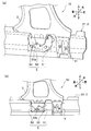
- FIG. 2 is a partially enlarged perspective view, partly broken, showing an extension by cutting a side sill at an edge of the center pillar of FIG. 1 in the vehicle body structure according to the first embodiment of the present invention. It is a figure which shows the extension which concerns on the 1st Embodiment of this invention, (a) is the elements on larger scale of FIG. 2, (b) is sectional drawing of a side sill.
- FIG. 1 It is a perspective view which shows the attachment state of the bulkhead in the vehicle body structure which concerns on the 2nd Embodiment of this invention, and looked at the lower part of the pillar inner from the back left side in the state which removed the side sill outer. It is a figure which shows the attachment state of the bulkhead in the vehicle body structure which concerns on the 2nd Embodiment of this invention, (a) is the perspective view seen from the front inner side in the state which removed the side sill inner, (b) is a front view FIG.
- the vehicle body structure 1 of a vehicle (not shown) according to the first embodiment of the present invention will be described in detail with reference to FIGS. 1 to 5 as appropriate.
- the direction of the vehicle is referred to as the front-rear direction, the up-down direction, and the vehicle width direction (left-right direction).
- FIG. 1 is a perspective view of the left side surface of the vehicle body as viewed from the front outer side, and shows the vehicle body structure from the front pillar 11 to the rear wheel house 12.
- a vehicle body structure 1 according to a first embodiment of the present invention includes a side sill 2 that extends in the front-rear direction at a side of the vehicle body, and a center pillar that is a pillar that extends upward by joining a lower end to the side sill 2.
- An inner 3, an extension 4 (see FIG. 2) joined to the lower end portion of the center pillar inner 3, and a cross member 9 joined to the side sill 2 and extending in the vehicle width direction are provided.
- the side sill 2 is a left and right pair, and the same structure can be applied to the right side of the vehicle body.
- a center pillar (center pillar inner 3) will be described as an example of the pillar, but the front pillar 11 and the rear pillar (not shown) can have the same structure.
- the center pillar inner is abbreviated as pillar inner 3.
- a pillar stiffener 30 is joined to the pillar inner 3 for reinforcement, and further, an outer panel (not shown) such as a body side panel is joined.
- an outer panel not shown
- the side sill 2 includes a side sill outer 21 disposed so as to project largely outward and a side sill inner 22 disposed so as to project slightly inward.
- the side sill outer 21 and the side sill inner 22 are joined by welding means such as spot welding at their upper and lower flange portions to form a closed cross section.
- the side sill outer 21 includes a pair of an outer upper wall 21a and an outer lower wall 21b that face each other, and an outer side wall 21c that is continuous with the vehicle width outer ends of the outer upper wall 21a and the outer lower wall 21b.
- the outer upper flange 21d extends upward from the vehicle width inner end portion of the outer upper wall 21a
- the outer lower flange 21e extends downward from the vehicle width inner end portion of the outer lower wall 21b.
- the side sill outer 21 is formed in a hat-shaped cross section, and is arranged in such a direction that the outer upper flange 21d and the outer lower flange 21e are inside, and the outer side wall 21c is projected outward.
- the side sill inner 22 includes a pair of an inner upper wall 22a and an inner lower wall 22b that face each other, an inner side wall 22c that is continuous with the vehicle width inner ends of the inner upper wall 22a and the inner lower wall 22b, and an inner upper wall 22a.
- An inner upper flange 22d extending upward from the width outer end portion and an inner lower flange 22e extending downward from the vehicle width outer end portion of the inner lower wall 22b are provided.
- the side sill inner 22 is formed in a hat-shaped cross section, and is arranged in such a direction that the inner upper flange 22d and the inner lower flange 22e are inward and the inner side wall 22c is projected inward.
- the pillar inner 3 is interposed between the outer upper flange 21d of the side sill outer 21 and the inner upper flange 22d of the side sill inner 22, and the side sill outer 21, the pillar inner 3, and the side sill inner 22 are joined together.
- the extension 4 is interposed between the outer lower flange 21e of the side sill outer 21 and the inner lower flange 22e of the side sill inner 22, and the side sill outer 21, the extension 4 and the side sill inner 22 are joined together. Yes.
- the pillar inner 3 is configured to have a shape in which the lower end portion joined to the side sill 2 is widened and the width becomes narrower toward the upper portion (see FIG. 4).
- the front side is formed to have a wider base than the rear side (see FIG. 4A).
- the lower end portion of the pillar inner 3 includes a joint portion 31 (see FIG. 4B) that is sandwiched and joined between the outer upper flange 21 d and the inner upper flange 22 d, and the joint portion 31.
- a first extension portion 32 and a second extension portion 33 provided so as to extend into the closed cross section of the side sill 2.
- the first extension portion 32 is disposed at the front end portion of the lower end of the pillar inner 3.
- the first extension portion 32 is formed with a convex boss portion 32a that protrudes outward along the vertical direction to form a ridge line in order to further improve the rigidity.
- the boss portion 32a is arranged in parallel in the front-rear direction so as to cover the entire width of the first extension portion 32 to form two lines.
- the second extension portion 33 is disposed at a substantially central portion at the lower end of the pillar inner 3 at a predetermined interval in the front-rear direction with respect to the first extension portion 32. Since the second extension portion 33 has the same shape as the first extension portion 32, detailed description thereof is omitted.
- extension part was provided in two places, the 1st extension part 32 and the 2nd extension part 33, considering the width
- the extension 4 includes a first extension 41 joined to the lower end portion of the first extension portion 32 and a second extension 42 joined to the lower end portion of the second extension portion 33.
- the lengths and widths of the first extension 32 and the second extension 33 are set so that the first extension 41 and the second extension 42 have the same predetermined shape and size.
- the first extension 41 has a rectangular flat plate shape, the upper edge is joined to the inside of the first extension 32 (see FIG. 5A), and the lower edge is the outer. It joins between the lower flange 21e and the inner lower flange 22e.
- the first extension 41 is disposed so as to partition the closed cross section formed by the side sill 2 along the vertical direction, and suppresses the vertical deformation and the compressive deformation of the side sill 2 in the vertical direction. Has the function of improving strength.
- the first extension 41 is formed with a convex bead 41a that protrudes inward along the vertical direction to form a ridge line in order to further improve the rigidity (see FIG. 3B).
- the bead 41a is arranged in parallel in the front-rear direction so as to cover the entire width of the first extension portion 32 to form three lines.
- the upper edge of the second extension 42 is joined to the inside of the second extension 33, and the lower edge is joined between the outer lower flange 21e and the inner lower flange 22e. Since the second extension 42 has the same configuration as the first extension 41, a detailed description thereof will be omitted.
- the first extension 41 and the second extension 42 are joined to the first extension portion 32 and the second extension portion 33, respectively. As shown in FIG. 5, it may be joined only to one of the first extension portion 32 and the second extension portion 33 in accordance with vehicle specifications and destination standard requirements.
- the vehicle body structure 1 configured as described above is provided with at least two extension portions 32 and 33, various rigidity designs can be flexibly adapted to the requirements of the vehicle specifications and destination standards.
- the extension 4 is joined to one of the first extension part 32 and the second extension part 33, and the extension 4 is omitted from the other, and the rigid design that is not arranged and both the two extension parts 32 and 33 are used. Rigid design with higher strength than joining extensions is also possible as appropriate. If necessary, by further increasing the number of the extension portions 32 and 33, a more suitable rigidity design can be achieved with a minimum increase in weight.
- the vehicle body structure 1 can be designed with various rigidity depending on the number and shape of the extensions 4 to be joined without changing the shape of the pillar inner 3 because the extension 4 is configured separately from the pillar inner 3. .
- the shape of the extension 4 can be standardized by unifying or standardizing the distance from the lower end of the extension portions 32 and 33 to the side sill 2, so that the short-term development can be achieved. It contributes suitably, can improve productivity and yield, and can aim at reduction of a man-hour.
- FIG. 6 to be referred to is a perspective view of the lower part of the pillar inner as viewed from the rear outer side with the side sill outer removed.
- A) of FIG. 7 is the perspective view seen from the front inner side in the state which removed the side sill inner,
- (b) is a front view.
- the vehicle body structure 10 according to the second embodiment includes an extension 41 joined to one of the first extension 32 and the second extension 33, and the first extension 32. And a bulkhead 5 disposed at a lower position overlapping the other second extension portion 33. Note that the vehicle body structure 10 is different from the vehicle body structure 1 according to the first embodiment in that the bulkhead 5 is mainly disposed, and the other components are the same. A detailed description will be omitted.
- the bulkhead 5 is reduced in weight by a pair of front and rear bulk front walls 51 and a rear wall 52 facing each other, and a bulk side wall 53 continuous to the vehicle width inner end of the bulk front wall 51 and the bulk rear wall 52. It has a U-shaped cross section. As shown in FIG. 8A, the bulkhead 5 is disposed so as to close the closed cross section of the side sill 2, is joined and held to the side sill outer 21, and the bulk side wall 53 is close to the side sill inner 22. In addition, a gap ⁇ is provided between the side sill inner 22 and the bulk side wall 53.
- the joint part between the bulkhead 5 and the side sill outer 21 includes an upper joint part 5A joined to the outer upper wall 21a, a lower joint part 5B joined to the outer lower wall 21b, and a side part joined to the outer side wall 21c. It is three places, 5 C of junction parts, and is joined by welding means, such as spot welding.
- the bulk front wall 51 includes a bulk front wall lower part 51a continuous with the bulk side wall 53, a front bent part 51b extending upward from the bulk front wall lower part 51a and bent forward.
- a bulk front wall upper portion 51c extending upward from the front bent portion 51b.
- the bulk rear wall 52 includes a bulk rear wall lower part 52a continuous with the bulk side wall 53, a rear bent part 52b extending upward from the bulk rear wall lower part 52a and bent rearward, and a bulk rear part extending upward from the rear bent part 52b. And an upper wall portion 52c.
- the bulk rear wall 52 is the left and right object with respect to the bulk front wall 51, the detailed description thereof is omitted because it has the same configuration.
- the bulk head 5 has a front bend portion 51b and a rear bend portion 52b so that the bulk front wall upper portion 51c and the bulk rear wall upper portion are larger than the distance between the bulk front wall lower portion 51a and the bulk rear wall lower portion 52a (span in the vehicle longitudinal direction).
- the interval 52c is wider. For this reason, it is possible to contribute to the compactness of the bulkhead 5 while avoiding interference with the second extension 33 on which the bulkhead 5 is disposed.
- the bulk side wall 53 includes a bead 53a extending along the longitudinal direction of the vehicle body in order to further improve the rigidity.
- the bead 53a protrudes outward in the vehicle width direction and has a convex shape.
- the rigidity of the bulk side wall 53 is improved. Therefore, the bulk deformation of the bulk front wall 51 and the bulk rear wall 52 can be suppressed.
- the bulk front wall 51 and the bulk rear wall 52 are integrally connected by the bulk side wall 53, the torsional rigidity of the bulk front wall 51 and the bulk rear wall 52 can be improved, and the deformation of the side sill 2 can be suppressed.
- the bulkhead 5 is disposed at a position overlapping the cross member 9 that supports the vehicle body floor 13 and extends in the vehicle width direction in the vehicle width direction.
- a load input to one side surface of the vehicle body can be reliably transmitted from the side sill outer 21 to the cross member 9 via the bulkhead 5 and the side sill inner 22, and further via the cross member 9.
- the extension 41 is joined to the first extension portion 32, and the bulkhead 5 is disposed at a lower position overlapping the second extension portion 33, so that the extension 4 is connected to the first extension portion 32 and the first extension portion 32.
- the rigidity in the vehicle width direction of the vehicle body and the load transmission characteristics can be improved as compared with the case where the two extension portions 33 are joined.
- the side sill inner 22 and the cross member 9 can be reliably and quickly supplied with the load input to the vehicle body through the bulk front wall 51 and the bulk rear wall 52 at the time of a side collision.
- the vehicle body floor 13 see FIG. 8A
- collision performance such as load transmission performance.
- the inner side of the bulkhead 5 so as to be close to the side sill inner 22 with a gap ⁇ , the vibration of the vehicle body is prevented from being transmitted from the side sill inner 22 to the vehicle body floor 13 when the vehicle is traveling.
- the living performance and running stability can be improved.
- attachment property of the side sill 2 which forms a closed cross section can be improved by joining the bulkhead 5 to the side sill outer 21 and not joining to the side sill inner 22.
- the vehicle body structure 10 enables the vehicle body rigidity design to be flexibly adapted to the requirements of the vehicle specifications and destination standards, and is the minimum necessary.
- By increasing the weight of the vehicle it is possible to ensure appropriate rigidity and strength, and to improve the overall performance of the vehicle, such as traveling performance, comfortability, fuel efficiency, and load transmission performance.
- the extension 41 is joined to the first extension portion 32 and the bulkhead 5 is disposed at a lower position overlapping the second extension portion 33. May be provided at three or more locations, and the bulkhead 5 may be disposed at two or more locations.
- first extension portion 32 and the second extension portion 33 are arranged separately and separately, but the first extension portion 32A and the second extension portion 33A are continuously connected. Alternatively, they may be integrally formed (see FIG. 9A).
- the extension 41 is joined to the first extension portion 32 of the first extension portion 32 and the second extension portion 33.
- one extension 43 may be disposed so as to join both the first extension portion 32 and the second extension portion 33.
- the bulkhead 5 having a U-shaped cross section is disposed at a lower position overlapping the second extension portion 33, but the present invention is not limited to this, and is limited to the shape of the U-shaped cross section. It may be in the form of a block instead of the one, and may be arranged in a lateral position that does not overlap the second extension portion 33.
Landscapes
- Engineering & Computer Science (AREA)
- Chemical & Material Sciences (AREA)
- Combustion & Propulsion (AREA)
- Transportation (AREA)
- Mechanical Engineering (AREA)
- Body Structure For Vehicles (AREA)
Abstract
Description
これにより、サイドシルの上下方向の潰れ変形および左右方向の圧縮変形を抑制して、剛性および強度を向上している。
これにより、バルクヘッド17でサイドシル16の断面変形ないしねじれを抑制して剛性および強度を向上するとともに、側突荷重をセンタピラー32およびサイドシル16からバルクヘッド17を介してクロスメンバ57に効率的に伝達して、側突時における車室内空間の変形量を抑制することができる。
つまり、車両の仕様や仕向け地によってさらに剛性を向上させたい場合や剛性よりも重量軽減や歩留まりを優先させたい場合には、仕様等に応じた新たな成形型を準備してセンタピラーインナの形状自体を変更しなければならず、短期開発に影響を与え、成形型のコストの増加や歩留まりの悪化等の製造上の課題があった。
つまり、車両の仕様や仕向け地によって高い剛性を確保できるバルクヘッドを追加しなければならないほどの車体剛性は求められていないが、バルクヘッドを廃止した場合には車体剛性が不足するようなときには好適に対応できないため、必要最小限の重量増加で必要な剛性および強度を満足することが困難であるという課題があった。
このため、本発明に係る車体構造は、必要最小限の重量増加で適切な剛性および強度等の車体性能を確保することができる。
このため、車両の仕様や仕向け地の要求規格に対して、柔軟に適合する車体の剛性設計が可能であるから、必要最小限の重量増加で適切な剛性および強度を確保することができる。
一方、バルクヘッドの内側をサイドシルインナに近接するように配置したことで、車両の走行時には、車体の振動がサイドシルインナから車体フロアへ伝達されることを回避して、居住性能および走行安定性を向上することができる。
また、前折り曲げ部および後折り曲げ部により、バルク前壁下部とバルク後壁下部の間隔(車体前後方向のスパン)よりもバルク前壁上部とバルク後壁上部の間隔の方を大きくすることができるため、バルクヘッドが配置される他方の延長部との干渉を回避しながらバルクヘッドのコンパクト化に寄与することができる。
このため、側突時に入力された荷重をバルク前壁およびバルク後壁を介して確実にサイドシルインナおよび車体フロアに伝達することで、荷重伝達性能等の衝突性能を向上することができる。
本発明の第1の実施形態に係る車体構造1は、図1に示すように、車体側部で前後方向に延びるサイドシル2と、サイドシル2に下端が接合されて上方に延びるピラーであるセンタピラーインナ3と、センタピラーインナ3の下端部に接合されたエクステンション4(図2参照)と、サイドシル2に接合され車幅方向に延びるクロスメンバ9と、を備えている。
サイドシルアウタ21は、ハット状断面に形成され、アウタ上フランジ21dとアウタ下フランジ21eを内側にして、アウタ側壁21cを外側に張り出すような向きに配設されている。
サイドシルインナ22は、ハット状断面に形成され、インナ上フランジ22dとインナ下フランジ22eを内側にして、インナ側壁22cを内側に張り出すような向きに配設されている。
サイドシル2の下部では、サイドシルアウタ21のアウタ下フランジ21eとサイドシルインナ22のインナ下フランジ22eとの間にエクステンション4が介在され、サイドシルアウタ21とエクステンション4とサイドシルインナ22とが一体として接合されている。
ピラーインナ3の下端部は、図3と図4に示すように、アウタ上フランジ21dとインナ上フランジ22dとに挟まれて接合された接合部31(図4(b)参照)と、接合部31からサイドシル2の閉断面内に延びるように設けられた第1の延長部32および第2の延長部33と、を備えている。
第2の延長部33は、第1の延長部32に対して前後方向に所定間隔を空けて、ピラーインナ3の下端の略中央部に配設されている。第2の延長部33は、第1の延長部32と同じ形状であるので詳細な説明は省略する。
エクステンション4の形状やサイズを所定の規格に集約化することで、短期開発に好適に寄与し、生産性および歩留まりを向上してコスト低減を図ることができる。
第1のエクステンション41は、サイドシル2が形成する閉断面を上下方向に沿って仕切るように配設され、サイドシル2の上下方向の潰れ変形、および車幅方向の圧縮変形を抑制し、断面剛性および強度を向上する機能を奏する。
なお、車体構造10は、第1の実施形態に係る車体構造1に対して、主としてバルクヘッド5を配設した点で相違し、他の構成は同様であるから同様な構成については同じ符号を付して、詳細な説明は省略する。
バルクヘッド5は、図8(a)に示すように、サイドシル2の閉断面を閉塞するように配設され、サイドシルアウタ21に接合されて保持され、サイドシルインナ22にバルク側壁53が近接するようにサイドシルインナ22とバルク側壁53との間に隙間δを設けて配設されている。
かかる構成により、バルク前壁51は、前折り曲げ部51bにより、車幅方向に沿って延びる凸状の稜線を備えたことで、車幅方向の荷重に対する耐力が増大するため、衝突荷重の伝達性能等の衝突性能を向上することができる。
バルク後壁52は、バルク前壁51に対して左右対象であるが、同様の構成であるので詳細な説明は省略する。
このため、バルクヘッド5が配置される第2の延長部33との干渉を回避しながらバルクヘッド5のコンパクト化に寄与することができる。
車体構造10は、バルク側壁53にビード53aを備えたことで、バルク側壁53の剛性が向上するため、バルク前壁51およびバルク後壁52の倒れ変形を抑止することができる。また、バルク前壁51とバルク後壁52をバルク側壁53で一体として連結したことで、バルク前壁51とバルク後壁52のねじれ剛性を向上させ、サイドシル2の変形を抑制することができる。
かかる構成により、車体の一方の側面に入力された荷重をサイドシルアウタ21からバルクヘッド5、およびサイドシルインナ22を介してクロスメンバ9へと確実に伝達することができ、さらにはクロスメンバ9を介して車体の他方の側面まで分散させて伝達することができるため、荷重伝達性能、荷重分散性能等の衝突性能をより向上することができる。
車体構造10は、第1の延長部32にエクステンション41を接合し、第2の延長部33に重なる下方位置にバルクヘッド5を配設したことで、エクステンション4が第1の延長部32および第2の延長部33の両方に接合された場合よりも、車体の車幅方向の剛性および荷重伝達特性を向上することができる。
一方、バルクヘッド5の内側をサイドシルインナ22に隙間δを設けて近接するように配置したことで、車両の走行時には、車体の振動がサイドシルインナ22から車体フロア13へ伝達されることを回避して、居住性能および走行安定性を向上することができる。また、バルクヘッド5をサイドシルアウタ21に接合しサイドシルインナ22には接合しないことで、閉断面を形成するサイドシル2の組み付け性を向上することができる。
2 サイドシル
3 ピラーインナ(ピラー)
4 エクステンション
5 バルクヘッド
5A 上部接合部
5B 下部接合部
5C 側部接合部
9 クロスメンバ
11 フロントピラー
12 リアホイルハウス
13 車体フロア
21 サイドシルアウタ
21a アウタ上壁
21b アウタ下壁
21c アウタ側壁
21d アウタ上フランジ
21e アウタ下フランジ
22 サイドシルインナ
22a インナ上壁
22b インナ下壁
22c インナ側壁
22d インナ上フランジ
22e インナ下フランジ
30 ピラースティフナ
31 接合部
32 第1の延長部
33 第2の延長部
41 エクステンション
41a ビード
42 エクステンション
51 バルク前壁
51a バルク前壁下部
51b 前折り曲げ部
51c バルク前壁上部
52 バルク後壁
52a バルク後壁下部
52b 後折り曲げ部
52c バルク後壁上部
53 バルク側壁
53a ビード
Claims (7)
- 車体側部で前後方向に延びるサイドシルと、
該サイドシルに下端が接合されて上方に延びるピラーと、を有する車体構造であって、
前記サイドシルは、
互いに対向する一対のアウタ上壁およびアウタ下壁と、該アウタ上壁およびアウタ下壁の車幅外側端部に連続するアウタ側壁と、前記アウタ上壁の車幅内側端部から上方に延びるアウタ上フランジと、前記アウタ下壁の車幅内側端部から下方に延びるアウタ下フランジと、によりハット状断面に形成されたサイドシルアウタと、
互いに対向する一対のインナ上壁およびインナ下壁と、該インナ上壁およびインナ下壁の車幅内側端部に連続するインナ側壁と、前記インナ上壁の車幅外側端部から上方に延びるインナ上フランジと、前記インナ下壁の車幅外側端部から下方に延びるインナ下フランジと、によりハット状断面に形成されたサイドシルインナと、を有し、
前記アウタ上フランジと前記インナ上フランジとを接合し、前記アウタ下フランジと前記インナ下フランジとを接合することで閉断面に構成され、
前記ピラーは、
下端に、前記アウタ上フランジと前記インナ上フランジとに挟まれて接合された接合部と、
該接合部から前記サイドシルの閉断面内に延びるとともに前後方向に所定間隔を空けて設けられた第1の延長部および第2の延長部と、を有し、
上端が前記第1の延長部および第2の延長部のうち少なくとも一方に接合されるとともに、下端が前記アウタ下フランジと前記インナ下フランジとに挟まれて接合されたエクステンションを備えること、
を特徴とする車体構造。 - 前記エクステンションは、上端が前記第1の延長部および第2の延長部に接合されていること、
を特徴とする請求範囲第1項に記載の車体構造。 - 前記第1の延長部および第2の延長部のうち一方の延長部に前記エクステンションを接合し、他方の延長部には前記エクステンションを接合せずに前記ピラーの下方に前記閉断面を閉塞するようにバルクヘッドを設け、
前記バルクヘッドは、前記サイドシルアウタに接合されるとともに、前記他方の延長部よりも車幅内側に延びて前記サイドシルインナに近接するように配置されていること、
を特徴とする請求範囲第1項に記載の車体構造。 - 前記バルクヘッドは、前記他方の延長部に重なる下方位置に配置され、
互いに対向する前後一対のバルク前壁およびバルク後壁と、
該バルク前壁およびバルク後壁の車幅内側端部に連続するバルク側壁と、によりコ字状断面に構成され、
前記バルク前壁は、前記バルク側壁に連続するバルク前壁下部と、該バルク前壁下部から上方に延びて前方に折り曲げられた前折り曲げ部と、該前折り曲げ部から上方に延びるバルク前壁上部と、を備え、
前記バルク後壁は、前記バルク側壁に連続するバルク後壁下部と、該バルク後壁下部から上方に延びて後方に折り曲げられた後折り曲げ部と、該後折り曲げ部から上方に延びるバルク後壁上部と、を備え、
前記バルク前壁上部と前記バルク後壁上部との間隔は、前記バルク前壁下部と前記バルク後壁下部との間隔よりも広いこと、
を特徴とする請求範囲第3項に記載の車体構造。 - 前記バルクヘッドは、前記アウタ上壁に接合される上部接合部と、前記アウタ下壁に接合される下部接合部と、前記アウタ側壁に接合される側部接合部と、を備えること、
を特徴とする請求範囲第3項に記載の車体構造。 - 前記バルクヘッドは、前記バルク側壁に前記車体前後方向に沿って延びるビードを備えること、
を特徴とする請求範囲第4項に記載の車体構造。 - 前記バルクヘッドは、車体フロアを支持し車幅方向に延びるクロスメンバに対して、車幅方向に重なる位置に配置されていること、
を特徴とする請求範囲第3項に記載の車体構造。
Priority Applications (6)
| Application Number | Priority Date | Filing Date | Title |
|---|---|---|---|
| BR112016004227-1A BR112016004227B1 (pt) | 2013-09-03 | 2014-08-01 | Estrutura de corpo de veículo |
| EP14842295.9A EP3042832B1 (en) | 2013-09-03 | 2014-08-01 | Vehicle body structure |
| US14/916,193 US9809258B2 (en) | 2013-09-03 | 2014-08-01 | Vehicle body structure |
| CN201480048737.9A CN105531180B (zh) | 2013-09-03 | 2014-08-01 | 车身构造 |
| MX2016002802A MX369637B (es) | 2013-09-03 | 2014-08-01 | Estructura de carroceria para vehiculo. |
| JP2015535389A JP6054536B2 (ja) | 2013-09-03 | 2014-08-01 | 車体構造 |
Applications Claiming Priority (2)
| Application Number | Priority Date | Filing Date | Title |
|---|---|---|---|
| JP2013182379 | 2013-09-03 | ||
| JP2013-182379 | 2013-09-03 |
Publications (1)
| Publication Number | Publication Date |
|---|---|
| WO2015033714A1 true WO2015033714A1 (ja) | 2015-03-12 |
Family
ID=52628199
Family Applications (1)
| Application Number | Title | Priority Date | Filing Date |
|---|---|---|---|
| PCT/JP2014/070360 WO2015033714A1 (ja) | 2013-09-03 | 2014-08-01 | 車体構造 |
Country Status (7)
| Country | Link |
|---|---|
| US (1) | US9809258B2 (ja) |
| EP (1) | EP3042832B1 (ja) |
| JP (1) | JP6054536B2 (ja) |
| CN (1) | CN105531180B (ja) |
| BR (1) | BR112016004227B1 (ja) |
| MX (1) | MX369637B (ja) |
| WO (1) | WO2015033714A1 (ja) |
Cited By (9)
| Publication number | Priority date | Publication date | Assignee | Title |
|---|---|---|---|---|
| US20160325786A1 (en) * | 2015-05-08 | 2016-11-10 | Volvo Car Corporation | Sill structure |
| CN108163055A (zh) * | 2016-12-07 | 2018-06-15 | 现代自动车株式会社 | 用于车辆的门槛结构 |
| JP2018114918A (ja) * | 2017-01-20 | 2018-07-26 | 本田技研工業株式会社 | 車体構造 |
| JP2018131061A (ja) * | 2017-02-15 | 2018-08-23 | スズキ株式会社 | サイドシル部の構造 |
| JP2019034600A (ja) * | 2017-08-10 | 2019-03-07 | トヨタ自動車株式会社 | 車両側部構造 |
| JP2019155988A (ja) * | 2018-03-08 | 2019-09-19 | 株式会社豊田自動織機 | 車体下部構造 |
| CN112092909A (zh) * | 2019-06-18 | 2020-12-18 | 马自达汽车株式会社 | 侧部车身结构 |
| JP2021066269A (ja) * | 2019-10-18 | 2021-04-30 | 本田技研工業株式会社 | 自動車のサイドシル構造 |
| JP2021066268A (ja) * | 2019-10-18 | 2021-04-30 | 本田技研工業株式会社 | 自動車のサイドシル構造 |
Families Citing this family (23)
| Publication number | Priority date | Publication date | Assignee | Title |
|---|---|---|---|---|
| EP3219588B1 (en) * | 2014-11-10 | 2023-04-05 | Nippon Steel Corporation | T-shaped joint structure |
| US9758192B2 (en) * | 2015-05-11 | 2017-09-12 | Ford Global Technologies, Llc | Underbody structure for absorbing energy to improve roof structure integrity during side impact |
| JP6197841B2 (ja) * | 2015-08-24 | 2017-09-20 | マツダ株式会社 | 車両の車体構造 |
| US9751567B2 (en) * | 2015-12-07 | 2017-09-05 | GM Global Technology Operations LLC | Rail assembly for controlled lateral deformation |
| FR3053654B1 (fr) * | 2016-07-05 | 2019-09-13 | Peugeot Citroen Automobiles Sa | Poutre metallique renforcee de vehicule automobile |
| US10399602B2 (en) * | 2017-02-17 | 2019-09-03 | Ford Global Technologies, Llc | Vehicle body including reinforcement on rocker panel |
| JP6575015B2 (ja) * | 2017-07-07 | 2019-09-18 | 本田技研工業株式会社 | 車体構造 |
| JP6922687B2 (ja) * | 2017-11-21 | 2021-08-18 | トヨタ自動車株式会社 | 車両前部構造 |
| JP6650920B2 (ja) * | 2017-12-14 | 2020-02-19 | 本田技研工業株式会社 | 車体のフロア構造 |
| JP6958399B2 (ja) * | 2018-02-05 | 2021-11-02 | トヨタ自動車株式会社 | 車両骨格構造 |
| FR3084048B1 (fr) * | 2018-07-18 | 2022-09-09 | Psa Automobiles Sa | Cloisons de longeron pour chargement en flexion en cas de choc lateral |
| US10953929B2 (en) * | 2018-11-09 | 2021-03-23 | Honda Motor Co., Ltd. | Shear plate for a side sill |
| RU188476U1 (ru) * | 2018-12-29 | 2019-04-15 | Публичное акционерное общество "АВТОВАЗ" | Конструкция боковины кузова легкового автомобиля |
| US10926812B2 (en) * | 2019-01-31 | 2021-02-23 | Toyota Motor Engineering & Manufacturing North America, Inc. | Tailgate with mass and performance optimized reinforcement structure |
| US11691675B2 (en) | 2019-02-28 | 2023-07-04 | Honda Motor Co., Ltd. | Vehicle body reinforcement structure |
| FR3094327B1 (fr) * | 2019-03-29 | 2021-07-30 | Psa Automobiles Sa | Armature de soubassement d'un châssis de véhicule, comprenant des longerons arrières latéraux pourvus d'un renfort |
| US11084538B2 (en) * | 2019-05-24 | 2021-08-10 | GM Global Technology Operations LLC | Multi-flange extrusion member |
| JP7259579B2 (ja) * | 2019-06-18 | 2023-04-18 | マツダ株式会社 | 側部車体構造 |
| JP2021024559A (ja) * | 2019-08-05 | 2021-02-22 | トヨタ自動車株式会社 | 車両の下部構造 |
| JP7363459B2 (ja) * | 2019-12-20 | 2023-10-18 | マツダ株式会社 | 車両の車体構造 |
| CN115103795A (zh) * | 2020-02-18 | 2022-09-23 | 日本制铁株式会社 | 车身构造部件以及车身构造部件的设计方法 |
| DE102020205713A1 (de) * | 2020-05-06 | 2021-11-11 | Volkswagen Aktiengesellschaft | Karosseriestruktur für ein Fahrzeug |
| JP2022071619A (ja) * | 2020-10-28 | 2022-05-16 | 三菱自動車工業株式会社 | 車両のセンターピラーの下部の結合構造 |
Citations (8)
| Publication number | Priority date | Publication date | Assignee | Title |
|---|---|---|---|---|
| JPS62138661U (ja) * | 1986-02-27 | 1987-09-01 | ||
| JPH0664558A (ja) * | 1992-08-24 | 1994-03-08 | Toyota Motor Corp | 車体のセンタピラー下部構造 |
| JPH06166384A (ja) | 1992-11-30 | 1994-06-14 | Suzuki Motor Corp | 自動車のアンダボディとサイドボディの結合構造 |
| JP2008001244A (ja) * | 2006-06-22 | 2008-01-10 | Toyota Motor Corp | 車体側部構造 |
| JP2008110626A (ja) * | 2006-10-27 | 2008-05-15 | Nippon Steel Corp | 自動車車体の結合構造 |
| WO2009038088A1 (ja) * | 2007-09-19 | 2009-03-26 | Toyota Jidosha Kabushiki Kaisha | 車体の側部構造 |
| JP2011240886A (ja) | 2010-05-20 | 2011-12-01 | Honda Motor Co Ltd | 車体側部構造 |
| JP2012035646A (ja) * | 2010-08-03 | 2012-02-23 | Toyota Motor Corp | 車体下部構造 |
Family Cites Families (12)
| Publication number | Priority date | Publication date | Assignee | Title |
|---|---|---|---|---|
| JPS6359783U (ja) * | 1986-10-09 | 1988-04-21 | ||
| JP3820867B2 (ja) * | 2000-10-17 | 2006-09-13 | 三菱自動車工業株式会社 | 車体構造 |
| JP4449758B2 (ja) * | 2005-01-21 | 2010-04-14 | 三菱自動車工業株式会社 | 車体構造 |
| CN101208236A (zh) * | 2005-05-10 | 2008-06-25 | 普而门工业有限公司 | 具有一体的焊接凸缘的一件式管形部件以及相关的制造方法 |
| JP5040722B2 (ja) | 2008-02-26 | 2012-10-03 | マツダ株式会社 | 自動車の下部車体構造 |
| JP5120268B2 (ja) * | 2009-01-14 | 2013-01-16 | トヨタ自動車株式会社 | ピラー上部結合構造 |
| JP5427895B2 (ja) * | 2009-12-22 | 2014-02-26 | 本田技研工業株式会社 | 車体側部構造 |
| US8678481B2 (en) * | 2009-12-22 | 2014-03-25 | Honda Motor Co., Ltd. | Structure for side portion of vehicle body |
| EP2388183B1 (en) | 2010-05-20 | 2012-07-04 | Honda Motor Co., Ltd. | Vehicle side body structure |
| US20120086238A1 (en) * | 2010-10-11 | 2012-04-12 | Gm Global Technology Operations, Inc. | Reinforced rocker panel structure |
| DE102010048851A1 (de) * | 2010-10-19 | 2012-04-19 | Gm Global Technology Operations Llc (N.D.Ges.D. Staates Delaware) | Schwelleranordnung einer Kraftfahrzeugkarosserie |
| US8888173B2 (en) * | 2013-03-28 | 2014-11-18 | Nissan North America, Inc. | Vehicle side body structure |
-
2014
- 2014-08-01 WO PCT/JP2014/070360 patent/WO2015033714A1/ja active Application Filing
- 2014-08-01 US US14/916,193 patent/US9809258B2/en active Active
- 2014-08-01 EP EP14842295.9A patent/EP3042832B1/en active Active
- 2014-08-01 JP JP2015535389A patent/JP6054536B2/ja active Active
- 2014-08-01 BR BR112016004227-1A patent/BR112016004227B1/pt active IP Right Grant
- 2014-08-01 MX MX2016002802A patent/MX369637B/es active IP Right Grant
- 2014-08-01 CN CN201480048737.9A patent/CN105531180B/zh active Active
Patent Citations (8)
| Publication number | Priority date | Publication date | Assignee | Title |
|---|---|---|---|---|
| JPS62138661U (ja) * | 1986-02-27 | 1987-09-01 | ||
| JPH0664558A (ja) * | 1992-08-24 | 1994-03-08 | Toyota Motor Corp | 車体のセンタピラー下部構造 |
| JPH06166384A (ja) | 1992-11-30 | 1994-06-14 | Suzuki Motor Corp | 自動車のアンダボディとサイドボディの結合構造 |
| JP2008001244A (ja) * | 2006-06-22 | 2008-01-10 | Toyota Motor Corp | 車体側部構造 |
| JP2008110626A (ja) * | 2006-10-27 | 2008-05-15 | Nippon Steel Corp | 自動車車体の結合構造 |
| WO2009038088A1 (ja) * | 2007-09-19 | 2009-03-26 | Toyota Jidosha Kabushiki Kaisha | 車体の側部構造 |
| JP2011240886A (ja) | 2010-05-20 | 2011-12-01 | Honda Motor Co Ltd | 車体側部構造 |
| JP2012035646A (ja) * | 2010-08-03 | 2012-02-23 | Toyota Motor Corp | 車体下部構造 |
Cited By (16)
| Publication number | Priority date | Publication date | Assignee | Title |
|---|---|---|---|---|
| US20160325786A1 (en) * | 2015-05-08 | 2016-11-10 | Volvo Car Corporation | Sill structure |
| CN106114648A (zh) * | 2015-05-08 | 2016-11-16 | 沃尔沃汽车公司 | 门槛结构 |
| US9896133B2 (en) * | 2015-05-08 | 2018-02-20 | Volvo Car Corporation | Sill structure |
| CN108163055A (zh) * | 2016-12-07 | 2018-06-15 | 现代自动车株式会社 | 用于车辆的门槛结构 |
| JP2018114918A (ja) * | 2017-01-20 | 2018-07-26 | 本田技研工業株式会社 | 車体構造 |
| JP2018131061A (ja) * | 2017-02-15 | 2018-08-23 | スズキ株式会社 | サイドシル部の構造 |
| JP2019034600A (ja) * | 2017-08-10 | 2019-03-07 | トヨタ自動車株式会社 | 車両側部構造 |
| JP2019155988A (ja) * | 2018-03-08 | 2019-09-19 | 株式会社豊田自動織機 | 車体下部構造 |
| CN112092909A (zh) * | 2019-06-18 | 2020-12-18 | 马自达汽车株式会社 | 侧部车身结构 |
| EP3753814A1 (en) * | 2019-06-18 | 2020-12-23 | Mazda Motor Corporation | Vehicle side body structure |
| JP2020203597A (ja) * | 2019-06-18 | 2020-12-24 | マツダ株式会社 | 側部車体構造 |
| US11136066B2 (en) | 2019-06-18 | 2021-10-05 | Mazda Motor Corporation | Vehicle side body structure |
| CN112092909B (zh) * | 2019-06-18 | 2022-11-01 | 马自达汽车株式会社 | 侧部车身结构 |
| JP7200838B2 (ja) | 2019-06-18 | 2023-01-10 | マツダ株式会社 | 側部車体構造 |
| JP2021066269A (ja) * | 2019-10-18 | 2021-04-30 | 本田技研工業株式会社 | 自動車のサイドシル構造 |
| JP2021066268A (ja) * | 2019-10-18 | 2021-04-30 | 本田技研工業株式会社 | 自動車のサイドシル構造 |
Also Published As
| Publication number | Publication date |
|---|---|
| BR112016004227B1 (pt) | 2021-08-03 |
| CN105531180B (zh) | 2017-10-13 |
| US20160194034A1 (en) | 2016-07-07 |
| EP3042832A4 (en) | 2017-05-10 |
| EP3042832B1 (en) | 2019-07-03 |
| US9809258B2 (en) | 2017-11-07 |
| JPWO2015033714A1 (ja) | 2017-03-02 |
| MX2016002802A (es) | 2016-10-28 |
| MX369637B (es) | 2019-11-13 |
| BR112016004227A2 (pt) | 2017-08-01 |
| JP6054536B2 (ja) | 2016-12-27 |
| EP3042832A1 (en) | 2016-07-13 |
| CN105531180A (zh) | 2016-04-27 |
Similar Documents
| Publication | Publication Date | Title |
|---|---|---|
| JP6054536B2 (ja) | 車体構造 | |
| JP5657025B2 (ja) | 車体後部構造 | |
| JP6128334B2 (ja) | 車両の後部車体構造 | |
| JP5756184B2 (ja) | 車体側部構造 | |
| JP6610576B2 (ja) | 車両骨格構造 | |
| JP5963060B2 (ja) | 車体後部のフロア構造 | |
| JP5337184B2 (ja) | 自動車の車体後部構造 | |
| JPWO2013069086A1 (ja) | 車両の樹脂フロア構造 | |
| JP6507816B2 (ja) | 車両後部構造 | |
| JP2018052499A (ja) | 車両骨格構造 | |
| JP6179383B2 (ja) | 車両の側部車体構造 | |
| JP5053406B2 (ja) | 自動車の車体構造 | |
| JP2010083393A (ja) | 車両前部構造 | |
| JP2017193297A (ja) | 車体前部構造 | |
| JP2011194945A (ja) | 車両側部結合部構造 | |
| WO2012095991A1 (ja) | 車体下部構造 | |
| CN111688814A (zh) | 车辆后部结构 | |
| JP5790437B2 (ja) | 車体下部構造 | |
| JP5470356B2 (ja) | 車体側部構造 | |
| JP2015112898A (ja) | 車両下部構造 | |
| JP5952181B2 (ja) | 車両の車体構造 | |
| JP5692057B2 (ja) | 車体下部構造 | |
| JP2014091346A (ja) | 車両後部構造 | |
| JP5189622B2 (ja) | 車体後部構造 | |
| JP5145376B2 (ja) | 車体前部構造 |
Legal Events
| Date | Code | Title | Description |
|---|---|---|---|
| WWE | Wipo information: entry into national phase |
Ref document number: 201480048737.9 Country of ref document: CN |
|
| 121 | Ep: the epo has been informed by wipo that ep was designated in this application |
Ref document number: 14842295 Country of ref document: EP Kind code of ref document: A1 |
|
| ENP | Entry into the national phase |
Ref document number: 2015535389 Country of ref document: JP Kind code of ref document: A |
|
| NENP | Non-entry into the national phase |
Ref country code: DE |
|
| WWE | Wipo information: entry into national phase |
Ref document number: 14916193 Country of ref document: US Ref document number: MX/A/2016/002802 Country of ref document: MX |
|
| REEP | Request for entry into the european phase |
Ref document number: 2014842295 Country of ref document: EP |
|
| REG | Reference to national code |
Ref country code: BR Ref legal event code: B01A Ref document number: 112016004227 Country of ref document: BR |
|
| WWE | Wipo information: entry into national phase |
Ref document number: 2014842295 Country of ref document: EP |
|
| WWE | Wipo information: entry into national phase |
Ref document number: IDP00201601893 Country of ref document: ID |
|
| ENP | Entry into the national phase |
Ref document number: 112016004227 Country of ref document: BR Kind code of ref document: A2 Effective date: 20160226 |