WO2014136809A1 - 雌端子金具 - Google Patents
雌端子金具 Download PDFInfo
- Publication number
- WO2014136809A1 WO2014136809A1 PCT/JP2014/055544 JP2014055544W WO2014136809A1 WO 2014136809 A1 WO2014136809 A1 WO 2014136809A1 JP 2014055544 W JP2014055544 W JP 2014055544W WO 2014136809 A1 WO2014136809 A1 WO 2014136809A1
- Authority
- WO
- WIPO (PCT)
- Prior art keywords
- contact piece
- elastic contact
- female terminal
- cut
- terminal fitting
- Prior art date
- Legal status (The legal status is an assumption and is not a legal conclusion. Google has not performed a legal analysis and makes no representation as to the accuracy of the status listed.)
- Ceased
Links
Images

Classifications
-
- H—ELECTRICITY
- H01—ELECTRIC ELEMENTS
- H01R—ELECTRICALLY-CONDUCTIVE CONNECTIONS; STRUCTURAL ASSOCIATIONS OF A PLURALITY OF MUTUALLY-INSULATED ELECTRICAL CONNECTING ELEMENTS; COUPLING DEVICES; CURRENT COLLECTORS
- H01R4/00—Electrically-conductive connections between two or more conductive members in direct contact, i.e. touching one another; Means for effecting or maintaining such contact; Electrically-conductive connections having two or more spaced connecting locations for conductors and using contact members penetrating insulation
- H01R4/28—Clamped connections, spring connections
- H01R4/48—Clamped connections, spring connections utilising a spring, clip, or other resilient member
-
- H—ELECTRICITY
- H01—ELECTRIC ELEMENTS
- H01R—ELECTRICALLY-CONDUCTIVE CONNECTIONS; STRUCTURAL ASSOCIATIONS OF A PLURALITY OF MUTUALLY-INSULATED ELECTRICAL CONNECTING ELEMENTS; COUPLING DEVICES; CURRENT COLLECTORS
- H01R13/00—Details of coupling devices of the kinds covered by groups H01R12/70 or H01R24/00 - H01R33/00
- H01R13/02—Contact members
- H01R13/10—Sockets for co-operation with pins or blades
- H01R13/11—Resilient sockets
- H01R13/113—Resilient sockets co-operating with pins or blades having a rectangular transverse section
-
- H—ELECTRICITY
- H01—ELECTRIC ELEMENTS
- H01R—ELECTRICALLY-CONDUCTIVE CONNECTIONS; STRUCTURAL ASSOCIATIONS OF A PLURALITY OF MUTUALLY-INSULATED ELECTRICAL CONNECTING ELEMENTS; COUPLING DEVICES; CURRENT COLLECTORS
- H01R13/00—Details of coupling devices of the kinds covered by groups H01R12/70 or H01R24/00 - H01R33/00
- H01R13/02—Contact members
- H01R13/10—Sockets for co-operation with pins or blades
- H01R13/11—Resilient sockets
- H01R13/115—U-shaped sockets having inwardly bent legs, e.g. spade type
Definitions
- the present invention relates to a female terminal fitting.
- the female terminal fitting disclosed in Patent Document 1 is disposed so as to be flexible inside the main body portion and a cylindrical main body portion (referred to as “electrical contact portion” in Patent Document 1) into which a male tab is inserted, and the main body portion And an elastic contact piece elastically contacting with a male tab (referred to as “male terminal” in Patent Document 1) inserted into the connector. Further, on both side walls of the main body portion, there are provided excessive deflection preventing pieces that are cut and raised inward to prevent excessive bending of the resilient contact pieces.
- the holes are opened in the both side walls with the formation of the excessive deflection preventing pieces, there is a possibility that foreign matter intrudes into the main body through the holes.
- the hole is located in the vicinity of the contact portion where the elastic contact piece contacts the male tab, foreign matter intruding from the hole may be attached to the contact portion, and the electrical connection reliability is impaired.
- the holes are provided on both side walls, there is a concern that the strength of the main body may be reduced.
- the present invention has been completed based on the above circumstances, and provides a female terminal fitting capable of preventing excessive bending of an elastic contact piece without making a hole in a side wall of a main body. With the goal.
- the present invention includes a cylindrical main body portion and an elastic contact piece disposed so as to be bendable inside the main body portion, and the male tab is inserted in the main body portion when a mating male tab is inserted.
- a female terminal fitting in which the elastic contact piece is bent and deformed toward the base wall of the main body portion in contact with the elastic contact piece, and the elastic contact piece and the deflection thereof are formed on the base wall of the main body portion It is characterized in that it is provided at an opposite position in the direction to provide an excessive deflection restricting portion which restricts an excessive deflection of the elastic contact piece.
- the excessive deflection restricting portion is provided on the base wall of the main body portion, it is possible to prevent the excessive bending of the elastic contact piece without opening the side wall of the main body portion.
- the excessive deflection restricting portions are provided in pairs at positions opposed to both widthwise ends of the elastic contact piece. As a result, the resilient contact piece which is about to be excessively flexed is stably supported by the excessive flexing restriction portion.
- An auxiliary spring piece which abuts on the elastic contact piece in the bending direction thereof and assists the spring force of the elastic contact piece is cut and raised from the cut-and-raised hole of the base wall in the main body portion.
- the deflection control portion is also cut and raised from the cut and raised hole. Since the excessive deflection restricting portion and the auxiliary spring piece share the single cut-and-raised hole, the structure of the main body can be simplified. Moreover, since a large hole does not open in a main-body part unnecessarily, the intensity
- the excessive deflection restricting portion is provided by being cut and raised from the cut and raised hole of the base wall, and closer to the elastic contact piece than portions of both sides of the base wall sandwiching the cut and raised hole. It is raised up and it has a control surface in the position which counters the above-mentioned elastic contact piece.
- the main body portion When inserted into the cavity of the connector housing, it can be resiliently locked to the lance projected to the inner wall of the cavity, and the main body portion has a height at which the bottom of the excessive deflection restricting portion is raised. In the area, a lance receiving space into which the lance can enter is provided. Since the approach amount of a lance is ensured using the height which the excessive deflection control part raised to the bottom, it is excellent in space efficiency.
- the base wall is provided with a locking projection that can be locked to the lance by striking out the edge of the cut and raised hole to the outside. Since the locking projections are provided by utilizing the cut and raised holes, the configuration is simplified as compared with the case where the locking projections are newly provided separately, and it is possible to cope with the miniaturization of the terminal fitting.
- Example 1 A first embodiment of the present invention will be described with reference to FIGS.
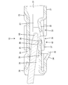
- the female terminal fitting 10 of the first embodiment is formed by bending a conductive metal plate or the like, and is provided with a cylindrical main body 20 into which the mating male tab 90 (see FIG. 6) is inserted. .
- the female terminal fitting 10 has a portion connected to the end of the electric wire (not shown) at the rear of the main body 20, the illustration and description thereof will be omitted here.
- the main body portion 20 has a rectangular cylindrical shape, and as shown in FIGS. 1 and 5, a base wall 21 substantially along the width direction, a pair of side walls 22 rising from both ends in the width direction of the base wall 21, and both side walls 22 And an opposing wall 23 extending from the upper end of one side wall 22 to the upper end of the other side wall 22.
- the opposing wall 23 is provided with a receiving portion 24 which is bent inward of the main body portion 20.
- the receiving portion 24 has a receiving surface 25 extending in the front-rear direction, and abuts on the upper surface of the male tab 90 so as to clamp the male tab 90 between elastic contact pieces 28 described later. It has become.
- both side walls 22 are provided with a pair of rattling portions 26 in the form of being struck inward.
- the two rattle-filled portions 26 are disposed on both sides in the width direction across the insertion path of the male tab 90 in the inside of the main body portion 20, and the male tab 90 is closed by closing the gap between both ends in the width direction of the male tab 90. Plays a role in restricting backlash in the width direction in the main body 20.
- a pair of stabilizers 27 in the form of being cut and raised outward is provided at the rear end portions of the side walls 22.
- the two stabilizers 27 are disposed at different heights on each of the side walls 22.
- the female terminal fitting 10 is inserted into the cavity (not shown) of the connector housing (not shown)
- the two stabilizers 27 are fitted and inserted into the guide grooves communicating with the cavity, thereby the female terminal
- the insertion operation of the metal fitting 10 is guided.
- the female terminal fitting 10 takes an incorrect posture other than the regular insertion posture
- the two stabilizers 27 are not inserted into the guide groove and interfere with the rear surface of the connector housing, whereby the female terminal fitting 10 has an incorrect posture. In this state, insertion into the cavity is prevented.
- a flexible resilient contact piece 28 is disposed inside the main body 20.
- the resilient contact piece 28 is formed by folding back a portion extending forward from the front end of the base wall 21 in the unfolded state, and extending upward from the front end of the base wall 21 in an upward slope.
- the resilient contact piece 28 can be bent and deformed in the vertical direction with the front end of the base wall 21 as a fulcrum.
- an embossed contact portion 29 is provided at the rear end of the resilient contact piece 28.
- a pair of overhanging portions 31 is provided so as to project to both sides on both sides sandwiching the contact portion 29.
- the resilient contact piece 28 When the male tab 90 is inserted into the main body portion 20, the resilient contact piece 28 is pressed by the male tab 90 and bent downward (to the base wall 21 side), and in this state, the contact portion 29 By resiliently contacting, the female terminal fitting 10 is conductively connected to the male tab 90 between the contact portion 29 and the receiving portion 24. As shown in FIG. 4, the middle of the elastic contact piece 28 in the front-rear direction is narrower than the front end and the rear end.
- a deflectable auxiliary spring piece 32 is disposed inside the main body 20 separately from the elastic contact piece 28.
- the auxiliary spring pieces 32 are cut and raised from the cut and raised holes 33 of the base wall 21 and extend forward from the rear end edge of the cut and raised holes 33 as shown in FIG.
- the front end portion of the auxiliary spring piece 32 is disposed so as to be able to abut on the rear end portion of the resilient contact piece 28 from below, and supports the resilient contact piece 28 downward. Play a role in assisting the power.
- the auxiliary spring piece 32 is narrower than the elastic contact piece 28 as a whole, and the front end portion of the auxiliary spring piece 32 is the widthwise central portion of the rear end portion of the elastic contact piece 28. It is possible to abut on.
- a locking projection 34 is provided at the front position of the base wall 21 with respect to the auxiliary spring piece 32.
- the lower end rear edge of the locking projection 34 is provided with a sub-protrusion 35 configured to project rearward.
- a lance 70 is lockable at the rear end edge of the sub projection 35, that is, at the front end edge of the cut and raised hole 33.
- the bottom raising cutout hole 36 is provided at the front end portion of the cut and raised hole 33 in a range extending from the base wall 21 to the lower end portions of the both side walls 22.
- a pair of over-deflection control portions 37 are provided in the inner side of the bottom-raising cut-and-raised hole 36 so as to be cut and raised inward.
- the two excessive deflection regulating portions 37 are one step higher than the reference surface of the base wall 21 (the wall surfaces of the base wall 21 at the front and rear sides sandwiching the cut and raised hole 33) so as to approach the elastic contact piece 28 side.
- the resilient contact piece 28 is disposed in a bottom-up state, and as shown in FIG.
- the resilient contact piece 28 is positioned opposite to the both overhanging portions 31 of the resilient contact piece 28 below (the bending direction of the resilient contact piece 28).
- a restricting surface 38 is disposed substantially horizontally so as to face the both overhanging portions 31.
- both excessive deflection regulating portions 37 are disposed on both sides of the front end portion of the auxiliary spring piece 32 in the width direction and below the front end portion of the auxiliary spring piece 32 in a natural state in the height direction. .
- both excessive deflection regulating portions 37 have a rectangular shape in a bottom view, and have a front-rear length exceeding the front-rear length of the both projecting portions 31 of the elastic contact piece 28.
- a lance receiving space 40 capable of receiving a lance 70 described later is opened below the both excessive deflection regulating portions 37 in the main body 20.
- the operation and effect of the female terminal fitting 10 of the first embodiment will be described.
- the tip of the lance 70 projected on the inner wall of the cavity is resilient to the lance receiving space 40 of the main body 20
- the female terminal fitting 10 is prevented from coming out of the cavity by being fitted in and the tip of the lance 70 being arranged to be able to be locked to the sub-projection 35 of the locking projection 34.
- both of the excessive deflection regulating portions 37 are positioned higher than the reference surface of the base wall 21 to increase the amount of recess in the height direction of the lance receiving space 40, and the tip of the lance 70 becomes the lance receiving space. It is possible to enter 40 deep.
- the male tab 90 mounted on the mating connector housing is inserted into the main body 20, and the resilient contact piece 28 is inserted into the male tab 90. While being abutted and bent downward, the auxiliary spring piece 32 is also pressed by the resilient contact piece 28 and bent downward.
- the male tab 90 is inserted at a regular depth, the male tab 90 is elastically sandwiched between the contact portion 29 of the resilient contact piece 28 and the receiving surface 25 of the receiving portion 24, whereby the female terminal fitting 10 is Conduction connection is normally made to male tab 90.
- the elastic contact piece 28 when the elastic contact piece 28 takes an incorrect insertion posture or the like and an excessive external force acts on the elastic contact piece 28, the elastic contact piece 28 together with the auxiliary spring piece 32 is excessively downward. It may be bent and deformed. However, according to the first embodiment, before the resilient contact piece 28 is excessively bent and deformed, the both projecting portions 31 of the resilient contact piece 28 are in line contact or in surface contact with the regulating surface 38 of both excessive deflection regulating portions 37. , And the further bending operation of the resilient contact piece 28 is restricted, thereby preventing the resilient contact piece 28 from being excessively flexed.
- the front end part of the auxiliary spring part is disposed at a position overlapping the both excessive deflection regulating parts 37 in the height direction.
- the elastic contact piece 28 is not formed even if the side wall 22 of the main body portion 20 is opened. It is possible to prevent excessive bending of the In this case, since the excessive deflection restricting portions 37 are provided in a pair at positions opposite to the overhanging portions 31 at both widthwise end portions of the elastic contact pieces 28, the elastic contact pieces 28 are the excessive deflection restricting portions 37. Stable support. Further, by arranging the auxiliary spring piece 32 between both the excessive deflection regulating portions 37, both the excessive deflection regulating portion 37 and the auxiliary spring piece 32 are disposed within the width of the base wall 21 with good space efficiency.
- both the excessive deflection restricting portions 37 and the auxiliary spring pieces 32 are cut and raised from the cut and raised holes 33 of the base wall 21 and one cut and raised holes 33 are shared, the configuration of the main body 20 is simplified. Be done. In addition, since a large hole does not open unnecessarily in the main body portion 20, it is possible to secure a predetermined strength of the main body portion 20.
- the excessive deflection restricting portion may be in contact with the auxiliary spring piece to restrict excessive bending of the elastic contact piece.
- One or three or more excessive deflection restricting portions may be provided on the base wall.
- the auxiliary spring pieces may be omitted.
- the excessive deflection restricting portion may be disposed at a position opposed to the widthwise central portion of the resilient contact piece.
- the excessive deflection restricting portion may be raised on the base wall, and the raised end may be disposed at a position facing the elastic contact piece.
- the excessive deflection restricting portion may be disposed at a position opposed to a portion in front of the rear end portion of the elastic contact piece.
Landscapes
- Connector Housings Or Holding Contact Members (AREA)
- Details Of Connecting Devices For Male And Female Coupling (AREA)
Abstract
雌端子金具(10)は、筒状の本体部(20)と、本体部(20)の内部に撓み可能に配置される弾性接触片(28)とを備える。本体部(20)に雄タブ(90)が挿入された場合に、雄タブ(90)が弾性接触片(28)と接触して、弾性接触片(28)が本体部(20)の基壁(21)へ向けて撓み変形させられる。本体部(20)の基壁(21)には、弾性接触片(28)とその撓み方向で対向する位置に配置されて、弾性接触片(28)の過度撓みを規制する過度撓み規制部(37)が設けられる。過度撓み規制部(37)は、基壁(21)の基準面に対して弾性接触片(28)側へ底上げされた形態とされている。
Description
本発明は、雌端子金具に関する。
特許文献1に開示の雌端子金具は、雄タブが挿入される筒状の本体部(特許文献1では「電気接触部」と呼称)と、本体部の内部に撓み可能に配置され、本体部に挿入される雄タブ(特許文献1では「雄端子」と呼称)に弾性的に接触する弾性接触片とを備えている。また、本体部の両側壁には、弾性接触片の過度撓みを防止するために内方へ向けて切り起こされた過度撓み防止片が設けられている。
上記の場合、過度撓み防止片の形成に伴い、両側壁に孔が開くため、孔を通して本体部内に異物が侵入する可能性があった。とくに、上記孔は、弾性接触片が雄タブと接触する接点部の近傍に位置しているため、孔から侵入した異物が接点部に付着する可能性があり、電気的な接続信頼性が損なわるおそれがあった。また、孔が両側壁に設けられているため、本体部の強度が低下する懸念もあった。
本発明は上記のような事情に基づいて完成されたものであって、本体部の側壁に孔を開けなくても弾性接触片の過度撓みを防止することが可能な雌端子金具を提供することを目的とする。
本発明は上記のような事情に基づいて完成されたものであって、本体部の側壁に孔を開けなくても弾性接触片の過度撓みを防止することが可能な雌端子金具を提供することを目的とする。
本発明は、筒状の本体部と、前記本体部の内部に撓み可能に配置される弾性接触片とを備え、前記本体部に相手側の雄タブが挿入された場合に、前記雄タブが前記弾性接触片と接触して、前記弾性接触片が前記本体部の基壁へ向けて撓み変形させられる雌端子金具であって、前記本体部の基壁には、前記弾性接触片とその撓み方向で対向する位置に配置されて、前記弾性接触片の過度撓みを規制する過度撓み規制部が設けられているところに特徴を有する。
本体部の基壁に過度撓み規制部が設けられているため、本体部の側壁に孔を開けなくても弾性接触片の過度撓みを防止することが可能となる。
本発明の好ましい形態を以下に示す。
前記過度撓み規制部が、前記弾性接触片の幅方向両端部と対向する位置に対をなして設けられている。これにより、過度撓みしようとする弾性接触片が過度撓み規制部に安定して支持される。
前記過度撓み規制部が、前記弾性接触片の幅方向両端部と対向する位置に対をなして設けられている。これにより、過度撓みしようとする弾性接触片が過度撓み規制部に安定して支持される。
前記本体部には、前記弾性接触片とその撓み方向で当接して前記弾性接触片のばね力を補助する補助バネ片が、前記基壁の切り起こし孔から切り起こされて設けられ、前記過度撓み規制部も、前記切り起こし孔から切り起こされてなる。過度撓み規制部と補助バネ片とが1つの切り起こし孔を共用して設けられるため、本体部の構成を簡素化することができる。また、本体部に不必要に大きな孔が開くことがないため、本体部の強度を確保することができる。
前記過度撓み規制部は、前記基壁の切り起こし孔から切り起こされて設けられ、且つ、前記基壁のうちの前記切り起こし孔を挟んだ両側の部分よりも前記弾性接触片に近づくように底上げされて、前記弾性接触片と対向する位置に規制面を有している。過度撓み規制部の規制面に弾性接触片が線接触又は面接触状態で当接することで、弾性接触片の過度撓みを安定して規制することができる。
コネクタハウジングのキャビティに挿入された場合に、前記キャビティの内壁に突成されたランスに弾性的に係止可能となるものであり、前記本体部には、前記過度撓み規制部の底上げの高さ範囲に、前記ランスが進入可能なランス受容空間が設けられている。過度撓み規制部が底上げされた高さを利用して、ランスの進入量が確保されるため、スペース効率に優れる。
前記基壁には、前記切り起こし孔の縁部を外側に叩き出すことで前記ランスに係止可能な係止突起が設けられている。切り起こし孔を利用して係止突起が設けられるため、係止突起が別に新設されるよりも構成が簡素化され、ひいては端子金具の小型化に対応可能となる。
<実施例1>
本発明の実施例1を図1~図6によって説明する。実施例1の雌端子金具10は、導電性の金属板を曲げ加工等して形成され、相手側の雄タブ90(図6を参照)が挿入される筒状の本体部20を備えている。なお、雌端子金具10は、本体部20の後方に電線(図示せず)の端末部に接続される部分を有しているが、ここではその図示及び説明を省略する。
本発明の実施例1を図1~図6によって説明する。実施例1の雌端子金具10は、導電性の金属板を曲げ加工等して形成され、相手側の雄タブ90(図6を参照)が挿入される筒状の本体部20を備えている。なお、雌端子金具10は、本体部20の後方に電線(図示せず)の端末部に接続される部分を有しているが、ここではその図示及び説明を省略する。
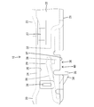
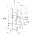
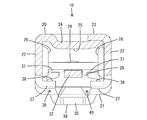
本体部20は、角筒状をなし、図1及び図5に示すように、幅方向にほぼ沿った基壁21と、基壁21の幅方向両端から立ち上がる一対の側壁22と、両側壁22のうちの一方の側壁22の上端部から他方の側壁22の上端部にかけて架け渡される対向壁23とを有している。対向壁23には、本体部20の内側へ折り曲げられてなる受け部24が設けられている。図3に示すように、受け部24は、前後方向に沿った受け面25を有し、雄タブ90の上面と当接して後述する弾性接触片28との間に雄タブ90を挟持するようになっている。
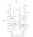
両側壁22の前端部には、図1及び図4に示すように、内方へ叩き出された形態をなす一対のガタ詰め部26が設けられている。両ガタ詰め部26は、本体部20の内部における雄タブ90の挿入経路を挟んだ幅方向両側に配置され、雄タブ90の幅方向両端面との間の隙間を詰めることにより、雄タブ90が本体部20内で幅方向にガタ付くのを規制する役割をはたす。
また、両側壁22の後端部には、図4に示すように、外方へ切り起こされた形態をなす一対のスタビライザ27が設けられている。図1に示すように、両スタビライザ27は、両側壁22のそれぞれで互いに異なる高さ位置に配置されている。ここで、雌端子金具10がコネクタハウジング(図示せず)のキャビティ(図示せず)に挿入されると、両スタビライザ27がキャビティと連通する案内溝に嵌合して挿入され、これによって雌端子金具10の挿入動作が案内されるようになっている。また、雌端子金具10が正規の挿入姿勢ではない不正姿勢をとる場合には、両スタビライザ27が案内溝に挿入されずにコネクタハウジングの後面に干渉し、これによって雌端子金具10が不正姿勢の状態でキャビティ内に挿入されるのが防止されるようになっている。
図3に示すように、本体部20の内部には、撓み可能な弾性接触片28が配置されている。弾性接触片28は、展開状態において基壁21の前端から前方に延びる部分を、後方へ折り返してなるものであり、基壁21の前端から後方へ上り勾配で延びる形態とされている。そして、弾性接触片28は、基壁21の前端を支点として上下方向に撓み変形可能とされている。図1及び図4に示すように、弾性接触片28の後端部には、上方へ叩き出されたエンボス状の接点部29が設けられている。また、弾性接触片28の後端部には、接点部29を挟んだ両側に、一対の張出部31が両側方に張り出して設けられている。
本体部20に雄タブ90が挿入されると、弾性接触片28が雄タブ90に押圧されて下方(基壁21側)に撓み変形させられ、その状態で、接点部29が雄タブ90に弾性的に接触することにより、雌端子金具10が接点部29と受け部24との間に雄タブ90と導通接続されるようになっている。なお、図4に示すように、弾性接触片28の前後方向途中は、前端部及び後端部よりも幅狭に括れた形態になっている。
また、図3に示すように、本体部20の内部には、弾性接触片28とは別に、撓み可能な補助バネ片32が配置されている。補助バネ片32は、基壁21の切り起こし孔33から切り起こされてなり、図4に示すように、切り起こし孔33の後端縁から前方へ向けて延びる形態とされている。図3に示すように、補助バネ片32の前端部は、弾性接触片28の後端部に下方から当接可能に配置され、弾性接触片28を下支えすることにより、弾性接触片28のバネ力を補助する役割をはたす。そして、図4に示すように、補助バネ片32は、全体として弾性接触片28よりも幅狭とされ、補助バネ片32の前端部は、弾性接触片28の後端部の幅方向中央部に当接可能とされている。
また、図3に示すように、基壁21における補助バネ片32よりも前方位置には、切り起こし孔33の前端縁から本体部20の外側となる下方へ向けて叩き出された爪状の係止突起34が設けられている。係止突起34の下端後縁には、後方へ向けて突出する形態をなす副突起35が設けられている。副突起35の後端縁、つまり切り起こし孔33の前端縁には、ランス70が係止可能とされている。
さて、切り起こし孔33の前端部には、図4及び図5に示すように、基壁21から両側壁22の下端部に跨る範囲に、底上げ用切り起こし孔36が設けられ、基壁21には、底上げ用切り起こし孔36から内方へ切り起こされてなる一対の過度撓み規制部37が設けられている。両過度撓み規制部37は、基壁21の基準面(基壁21のうち、切り起こし孔33を挟んだ前後両側の部分の壁面)に対して、弾性接触片28側へ近づくように一段高い位置に底上げされた状態で配置され、図5に示すように、弾性接触片28の両張出部31とその下方(弾性接触片28の撓み方向)で対向する位置に、弾性接触片28の両張出部31と対向するように略水平に配置された規制面38を有している。また、両過度撓み規制部37は、幅方向に関して補助バネ片32の前端部を挟んだ両側で、且つ高さ方向に関して自然状態にある補助バネ片32の前端部よりも下方に配置されている。さらに、図4に示すように、両過度撓み規制部37は、底面視で矩形状をなし、弾性接触片28の両張出部31の前後長を超える前後長を有している。なお、本体部20における両過度撓み規制部37の下方には、図3に示すように、後述するランス70を受容可能なランス受容空間40が開放されている。
次に、実施例1の雌端子金具10の作用効果を説明する。
コネクタハウジングのキャビティ内に雌端子金具10が挿入され、雌端子金具10が正規挿入位置に至ると、キャビティの内壁に突成されたランス70の先端部が本体部20のランス受容空間40に弾性的に嵌まり込み、ランス70の先端部が係止突起34の副突起35に係止可能に配置されることで、雌端子金具10がキャビティ内に抜け止めされる。この場合、両過度撓み規制部37が基壁21の基準面よりも高位に位置することにより、ランス受容空間40の高さ方向の凹み量が増大して、ランス70の先端部がランス受容空間40に深く進入することが可能となっている。
コネクタハウジングのキャビティ内に雌端子金具10が挿入され、雌端子金具10が正規挿入位置に至ると、キャビティの内壁に突成されたランス70の先端部が本体部20のランス受容空間40に弾性的に嵌まり込み、ランス70の先端部が係止突起34の副突起35に係止可能に配置されることで、雌端子金具10がキャビティ内に抜け止めされる。この場合、両過度撓み規制部37が基壁21の基準面よりも高位に位置することにより、ランス受容空間40の高さ方向の凹み量が増大して、ランス70の先端部がランス受容空間40に深く進入することが可能となっている。
続いて、コネクタハウジングが相手側コネクタハウジング(図示せず)に嵌合されると、相手側コネクタハウジングに装着された雄タブ90が本体部20に挿入され、弾性接触片28が雄タブ90に当接して下方へ撓み変形させられるとともに、補助バネ片32も弾性接触片28に押圧されて下方へ撓み変形させられる。雄タブ90が正規深さで挿入されると、弾性接触片28の接点部29と受け部24の受け面25との間に雄タブ90が弾性的に挟み込まれ、これによって雌端子金具10が雄タブ90に正規に導通接続される。
一方、図6に示すように、弾性接触片28が不正な挿入姿勢をとる等して、弾性接触片28に過剰な外力が作用すると、弾性接触片28が補助バネ片32ともども下方へ過度に撓み変形させられる可能性がある。しかるに実施例1によれば、弾性接触片28が過度に撓み変形させられる前に、弾性接触片28の両張出部31が両過度撓み規制部37の規制面38に線接触又は面接触状態で当接して、弾性接触片28のそれ以上の撓み動作が規制されるため、弾性接触片28が過度撓みする事態が防止される。なお、弾性接触片28の両張出部31が両過度撓み規制部37に当接した状態では、補助バネ部の前端部が高さ方向に関して両過度撓み規制部37と重なる位置に配置される。
以上説明したように、実施例1によれば、本体部20の基壁21に過度撓み規制部37が設けられているため、本体部20の側壁22に孔を開けなくても弾性接触片28の過度撓みを防止することが可能となる。この場合に、過度撓み規制部37が弾性接触片28の幅方向両端部における両張出部31と対向する位置に対をなして設けられているため、弾性接触片28が過度撓み規制部37に安定して支持される。また、補助バネ片32が両過度撓み規制部37の間に配置されることにより、基壁21の幅内に両過度撓み規制部37と補助バネ片32とがスペース効率良く配置される。
さらに、両過度撓み規制部37及び補助バネ片32がいずれも基壁21の切り起こし孔33から切り起こされ、1つの切り起こし孔33を共用しているため、本体部20の構成が簡素化される。また、本体部20に不必要に大きな孔が開くことがないため、本体部20の所定の強度を確保することが可能となる。
<他の実施例>
本発明は上記記述及び図面によって説明した実施例に限定されるものではなく、例えば次のような態様も本発明の技術的範囲に含まれる。
(1)過度撓み規制部が、補助バネ片に当接して弾性接触片の過度撓みを規制する構成であってもよい。
(2)過度撓み規制部が、基壁に1つ又は3つ以上設けられるものであってもよい。
(3)場合によっては、補助バネ片は省略されてもよい。この場合、過度撓み規制部は、弾性接触片の幅方向中央部と対向する位置に配置されるものであってもよい。
(4)過度撓み規制部は、基壁に立ち上げ形成され、その立ち上げ端が弾性接触片と対向する位置に配置されるものであってもよい。
(5)過度撓み規制部は、弾性接触片における後端部よりも前方の部分と対向する位置に配置されるものであってもよい。
本発明は上記記述及び図面によって説明した実施例に限定されるものではなく、例えば次のような態様も本発明の技術的範囲に含まれる。
(1)過度撓み規制部が、補助バネ片に当接して弾性接触片の過度撓みを規制する構成であってもよい。
(2)過度撓み規制部が、基壁に1つ又は3つ以上設けられるものであってもよい。
(3)場合によっては、補助バネ片は省略されてもよい。この場合、過度撓み規制部は、弾性接触片の幅方向中央部と対向する位置に配置されるものであってもよい。
(4)過度撓み規制部は、基壁に立ち上げ形成され、その立ち上げ端が弾性接触片と対向する位置に配置されるものであってもよい。
(5)過度撓み規制部は、弾性接触片における後端部よりも前方の部分と対向する位置に配置されるものであってもよい。
10…雌端子金具
20…本体部
21…基壁
22…側壁
28…弾性接触片
31…張出部
32…補助バネ片
33…切り起こし孔
37…過度撓み規制部
90…雄タブ
20…本体部
21…基壁
22…側壁
28…弾性接触片
31…張出部
32…補助バネ片
33…切り起こし孔
37…過度撓み規制部
90…雄タブ
Claims (6)
- 筒状の本体部と、前記本体部の内部に撓み可能に配置される弾性接触片とを備え、前記本体部に相手側の雄タブが挿入された場合に、前記雄タブが前記弾性接触片と接触して、前記弾性接触片が前記本体部の基壁へ向けて撓み変形させられる雌端子金具であって、
前記本体部の基壁には、前記弾性接触片とその撓み方向で対向する位置に配置されて、前記弾性接触片の過度撓みを規制する過度撓み規制部が設けられていることを特徴とする雌端子金具。 - 前記過度撓み規制部が、前記弾性接触片の幅方向両端部と対向する位置に対をなして設けられていることを特徴とする請求項1記載の雌端子金具。
- 前記本体部には、前記弾性接触片とその撓み方向で当接して前記弾性接触片のばね力を補助する補助バネ片が、前記基壁の切り起こし孔から切り起こされて設けられ、前記過度撓み規制部も、前記切り起こし孔から切り起こされてなることを特徴とする請求項1又は2記載の雌端子金具。
- 前記過度撓み規制部は、前記基壁の切り起こし孔から切り起こされて設けられ、且つ、前記基壁のうちの前記切り起こし孔を挟んだ両側の部分よりも前記弾性接触片に近づくように底上げされて、前記弾性接触片と対向する位置に規制面を有していることを特徴とする請求項1ないし3のいずれか1項記載の雌端子金具。
- コネクタハウジングのキャビティに挿入された場合に、前記キャビティの内壁に突成されたランスに弾性的に係止可能となるものであり、
前記本体部には、前記過度撓み規制部の底上げの高さ範囲に、前記ランスが進入可能なランス受容空間が設けられていることを特徴とする請求項4記載の雌端子金具。 - 前記基壁には、前記切り起こし孔の縁部を外側に叩き出すことで前記ランスに係止可能な係止突起が設けられていることを特徴とする請求項5記載の雌端子金具。
Priority Applications (1)
| Application Number | Priority Date | Filing Date | Title |
|---|---|---|---|
| US14/771,884 US9515396B2 (en) | 2013-03-05 | 2014-03-05 | Female terminal fitting |
Applications Claiming Priority (2)
| Application Number | Priority Date | Filing Date | Title |
|---|---|---|---|
| JP2013-043125 | 2013-03-05 | ||
| JP2013043125A JP2014170709A (ja) | 2013-03-05 | 2013-03-05 | 雌端子金具 |
Publications (1)
| Publication Number | Publication Date |
|---|---|
| WO2014136809A1 true WO2014136809A1 (ja) | 2014-09-12 |
Family
ID=51491321
Family Applications (1)
| Application Number | Title | Priority Date | Filing Date |
|---|---|---|---|
| PCT/JP2014/055544 Ceased WO2014136809A1 (ja) | 2013-03-05 | 2014-03-05 | 雌端子金具 |
Country Status (3)
| Country | Link |
|---|---|
| US (1) | US9515396B2 (ja) |
| JP (1) | JP2014170709A (ja) |
| WO (1) | WO2014136809A1 (ja) |
Cited By (2)
| Publication number | Priority date | Publication date | Assignee | Title |
|---|---|---|---|---|
| WO2016097903A1 (en) | 2014-12-19 | 2016-06-23 | Szikra Istvan | Electric connector device primarily for the hermetically sealed compressor of refrigerators |
| EP3588687A1 (en) * | 2018-06-26 | 2020-01-01 | Yazaki Corporation | Terminal metal fitting |
Families Citing this family (10)
| Publication number | Priority date | Publication date | Assignee | Title |
|---|---|---|---|---|
| JP2014160545A (ja) * | 2013-02-19 | 2014-09-04 | Sumitomo Wiring Syst Ltd | 雌端子金具 |
| JP2014170709A (ja) * | 2013-03-05 | 2014-09-18 | Sumitomo Wiring Syst Ltd | 雌端子金具 |
| JP6776050B2 (ja) * | 2016-08-01 | 2020-10-28 | 日本航空電子工業株式会社 | 雌端子及びそれを備えたコネクタ |
| JP6239064B1 (ja) * | 2016-08-08 | 2017-11-29 | 目黒設計合同会社 | 雌側端子 |
| JP6265295B1 (ja) * | 2017-06-14 | 2018-01-24 | Smk株式会社 | コンタクト |
| JP6812923B2 (ja) * | 2017-07-27 | 2021-01-13 | 住友電装株式会社 | 端子金具 |
| JP2019153502A (ja) * | 2018-03-05 | 2019-09-12 | 住友電装株式会社 | コネクタ |
| JP7052665B2 (ja) * | 2018-10-02 | 2022-04-12 | 株式会社オートネットワーク技術研究所 | 雌端子 |
| JP7218718B2 (ja) * | 2019-12-20 | 2023-02-07 | 住友電装株式会社 | 端子金具およびコネクタ |
| JP7622537B2 (ja) | 2021-04-27 | 2025-01-28 | I-Pex株式会社 | 端子 |
Citations (6)
| Publication number | Priority date | Publication date | Assignee | Title |
|---|---|---|---|---|
| JPH0729759U (ja) * | 1993-10-27 | 1995-06-02 | 住友電装株式会社 | コネクタ用雌端子金具 |
| JPH0831490A (ja) * | 1994-07-11 | 1996-02-02 | Sumitomo Wiring Syst Ltd | 雌端子金具 |
| JP2001210418A (ja) * | 2000-01-28 | 2001-08-03 | Sumitomo Wiring Syst Ltd | 雌端子金具 |
| JP2002190336A (ja) * | 2000-12-21 | 2002-07-05 | Sumitomo Wiring Syst Ltd | 端子金具 |
| JP2006120370A (ja) * | 2004-10-19 | 2006-05-11 | Sumitomo Wiring Syst Ltd | 雌端子金具 |
| JP2012199069A (ja) * | 2011-03-22 | 2012-10-18 | Yazaki Corp | コネクタ端子 |
Family Cites Families (89)
| Publication number | Priority date | Publication date | Assignee | Title |
|---|---|---|---|---|
| JPS60110930U (ja) * | 1983-12-27 | 1985-07-27 | アムプ インコ−ポレ−テツド | 雌形電気接触子 |
| JPH0429508Y2 (ja) * | 1988-12-05 | 1992-07-16 | ||
| JP2686199B2 (ja) * | 1992-01-28 | 1997-12-08 | 矢崎総業株式会社 | 雌型端子金具 |
| JPH0729759A (ja) | 1993-06-25 | 1995-01-31 | Toshiba Corp | 静止誘導電器の組立方法及び組立装置 |
| JP2725755B2 (ja) * | 1993-08-31 | 1998-03-11 | 矢崎総業株式会社 | 端子金具 |
| FR2711853B1 (fr) * | 1993-10-26 | 1995-12-01 | Cinch Connecteurs Sa | Organe de contact électrique femelle. |
| JP2596910Y2 (ja) * | 1993-11-30 | 1999-06-28 | 日本エー・エム・ピー株式会社 | 雌型コンタクト |
| JP3112225B2 (ja) * | 1993-12-27 | 2000-11-27 | 矢崎総業株式会社 | 電気接続子 |
| JPH07296873A (ja) * | 1994-04-21 | 1995-11-10 | Amp Japan Ltd | 雌型コンタクト |
| US5791945A (en) * | 1995-04-13 | 1998-08-11 | The Whitaker Corporation | High force contact |
| GB9519884D0 (en) * | 1995-09-29 | 1995-11-29 | Amp Great Britain | Electrical receptacle terminals |
| US6062918A (en) * | 1996-07-01 | 2000-05-16 | The Whitaker Corporation | Electrical receptacle contact assembly |
| JP3319292B2 (ja) * | 1996-07-26 | 2002-08-26 | 住友電装株式会社 | 雌側端子金具 |
| EP0932917B1 (en) * | 1996-10-17 | 2000-05-24 | The Whitaker Corporation | Electrical connector having a housing and an electrical contact |
| DE19705509C2 (de) * | 1997-02-13 | 1999-04-29 | Siemens Ag | Einstückige Kontaktfeder |
| JP3544133B2 (ja) * | 1999-01-20 | 2004-07-21 | 住友電装株式会社 | 雌側端子金具 |
| JP3473899B2 (ja) * | 1999-05-11 | 2003-12-08 | 矢崎総業株式会社 | 雌端子 |
| AU5157800A (en) * | 1999-05-28 | 2000-12-18 | Whitaker Corporation, The | Electrical contact receptacle terminal to mate with round and rectangular pins |
| JP3646778B2 (ja) * | 1999-06-17 | 2005-05-11 | 矢崎総業株式会社 | 端子金具 |
| JP3473521B2 (ja) * | 1999-10-08 | 2003-12-08 | 住友電装株式会社 | 雌端子金具 |
| JP2001155808A (ja) * | 1999-11-30 | 2001-06-08 | Yazaki Corp | 雌形接続端子 |
| JP2002063961A (ja) * | 2000-06-07 | 2002-02-28 | Yazaki Corp | 雌端子、及び、雌端子と雄端子との接続構造 |
| JP2002184479A (ja) * | 2000-12-18 | 2002-06-28 | Jst Mfg Co Ltd | 雌圧着端子 |
| JP3576488B2 (ja) * | 2000-12-18 | 2004-10-13 | 日本圧着端子製造株式会社 | 雌端子 |
| US6293833B1 (en) * | 2001-01-05 | 2001-09-25 | Yazaki North America | Low insertion force, high contact force terminal spring |
| JP4401580B2 (ja) * | 2001-02-15 | 2010-01-20 | 株式会社オートネットワーク技術研究所 | コネクタの端子構造 |
| JP3754304B2 (ja) * | 2001-02-16 | 2006-03-08 | 矢崎総業株式会社 | ジョイントコネクタ |
| JP2003243076A (ja) | 2002-02-15 | 2003-08-29 | Sumitomo Wiring Syst Ltd | 雌端子金具およびコネクタ |
| JP3767506B2 (ja) * | 2002-04-03 | 2006-04-19 | 住友電装株式会社 | 雌側端子金具 |
| DE60312848T2 (de) * | 2002-05-17 | 2007-09-06 | Mitsubishi Cable Industries, Ltd. | Verbindungsanschluss |
| JP3770205B2 (ja) * | 2002-05-24 | 2006-04-26 | 住友電装株式会社 | 端子金具 |
| JP2004006132A (ja) * | 2002-05-31 | 2004-01-08 | Sumitomo Wiring Syst Ltd | 端子金具 |
| JP2004253166A (ja) * | 2003-02-18 | 2004-09-09 | Yazaki Corp | 雌端子 |
| WO2004114467A1 (ja) * | 2003-06-18 | 2004-12-29 | Ryosei Electro-Circuit Systems, Ltd. | 接続端子 |
| JP4075825B2 (ja) * | 2004-02-26 | 2008-04-16 | 住友電装株式会社 | 雌端子金具 |
| JP4013151B2 (ja) * | 2004-04-13 | 2007-11-28 | 住友電装株式会社 | 雌端子金具 |
| EP1643599B1 (en) * | 2004-09-29 | 2008-12-17 | Sumitomo Wiring Systems, Ltd. | A terminal fitting and a connector using such a terminal fitting |
| JP4483601B2 (ja) * | 2005-01-28 | 2010-06-16 | 住友電装株式会社 | 雌端子金具 |
| CN101133527B (zh) * | 2005-02-09 | 2010-05-19 | Fci公司 | 包括弹簧接触板的插孔电触头 |
| US7387550B2 (en) * | 2005-07-21 | 2008-06-17 | Tyco Electronics Corporation | Dual beam receptacle contact |
| DE602006019809D1 (de) * | 2005-11-15 | 2011-03-10 | Sumitomo Wiring Systems | Verbinder |
| JP4482823B2 (ja) * | 2005-12-26 | 2010-06-16 | 住友電装株式会社 | 端子金具 |
| US7252564B1 (en) * | 2006-01-27 | 2007-08-07 | Delphi Technologies, Inc. | Female electrical connector having crimping portions of double thickness |
| DE102006009075A1 (de) * | 2006-02-28 | 2007-08-30 | Robert Bosch Gmbh | Elektrischer Steckverbinder mit innen liegender Blattfeder |
| JP4749919B2 (ja) * | 2006-04-12 | 2011-08-17 | 日本圧着端子製造株式会社 | バネ出し雌端子 |
| JP2008123720A (ja) * | 2006-11-08 | 2008-05-29 | Tyco Electronics Amp Kk | 雌型コンタクト |
| JP4858293B2 (ja) * | 2007-05-08 | 2012-01-18 | 住友電装株式会社 | 雌端子金具 |
| US7530859B2 (en) * | 2007-05-08 | 2009-05-12 | Tyco Electronics Corporation | Electrical contact |
| DE102008017043B3 (de) * | 2008-04-03 | 2009-09-03 | Lear Corp., Southfield | Verfahren zur Herstellung eines Buchsenanschlussstückes |
| JP5285985B2 (ja) * | 2008-07-17 | 2013-09-11 | 矢崎総業株式会社 | 雌型端子金具 |
| US8021200B2 (en) * | 2008-08-04 | 2011-09-20 | Tyco Electronics Corporation | Socket contact |
| US20100029146A1 (en) * | 2008-08-04 | 2010-02-04 | Tyco Electronics Corporation | Socket contact |
| DE102009057819A1 (de) * | 2009-01-08 | 2010-09-23 | Sumitomo Wiring Systems, Ltd., Yokkaichi | Anschlußpaßstück und Verfahren zum Bilden desselben |
| JP2010186692A (ja) * | 2009-02-13 | 2010-08-26 | Yazaki Corp | 接続端子 |
| JP5233822B2 (ja) * | 2009-04-24 | 2013-07-10 | 住友電装株式会社 | 端子金具 |
| JP5251819B2 (ja) * | 2009-10-09 | 2013-07-31 | 住友電装株式会社 | 雌端子金具 |
| JP2013508935A (ja) * | 2009-10-26 | 2013-03-07 | モレックス インコーポレイテド | 小型レセプタクル端子 |
| JP5480612B2 (ja) * | 2009-12-17 | 2014-04-23 | 矢崎総業株式会社 | ヒューズ用端子 |
| JP5631017B2 (ja) * | 2010-02-04 | 2014-11-26 | 矢崎総業株式会社 | コネクタ用のメス端子 |
| JP2011181330A (ja) * | 2010-03-01 | 2011-09-15 | Sumitomo Wiring Syst Ltd | 端子金具 |
| JP2011249169A (ja) * | 2010-05-27 | 2011-12-08 | Sumitomo Wiring Syst Ltd | 端子金具 |
| JP2012079505A (ja) * | 2010-09-30 | 2012-04-19 | Japan Aviation Electronics Industry Ltd | コネクタ組立体 |
| JP2012089318A (ja) * | 2010-10-19 | 2012-05-10 | Sumitomo Wiring Syst Ltd | 端子金具 |
| US8333622B2 (en) * | 2010-12-06 | 2012-12-18 | Delphi Technologies, Inc. | Dual contact beam terminal |
| JP5614369B2 (ja) * | 2011-05-19 | 2014-10-29 | 住友電装株式会社 | 端子金具 |
| US8911253B2 (en) * | 2011-06-13 | 2014-12-16 | Tyco Electronics Corporation | Receptacle contact |
| JP5872803B2 (ja) * | 2011-06-24 | 2016-03-01 | 矢崎総業株式会社 | 雌型端子金具の製造方法 |
| JP2013026155A (ja) * | 2011-07-25 | 2013-02-04 | Yazaki Corp | 防水コネクタ用端子 |
| JP5682520B2 (ja) * | 2011-09-14 | 2015-03-11 | 住友電装株式会社 | 端子金具 |
| JP2013098088A (ja) * | 2011-11-02 | 2013-05-20 | Sumitomo Wiring Syst Ltd | 雌型端子金具 |
| JP2013137949A (ja) * | 2011-12-28 | 2013-07-11 | Yazaki Corp | 端子構造 |
| DE102012002145A1 (de) * | 2012-02-04 | 2013-08-08 | Kostal Kontakt Systeme Gmbh | Hülsenkontakt für einen elektrischen Nullkraftsteckverbinder |
| JP5737216B2 (ja) * | 2012-03-28 | 2015-06-17 | 住友電装株式会社 | コネクタ |
| JP5757426B2 (ja) * | 2012-03-28 | 2015-07-29 | 住友電装株式会社 | コネクタ |
| JP2013229222A (ja) * | 2012-04-26 | 2013-11-07 | Sumitomo Wiring Syst Ltd | 端子金具 |
| US8974256B2 (en) * | 2012-04-26 | 2015-03-10 | Sumitomo Wiring Systems, Ltd. | Terminal fitting and production method therefor |
| DE102013004403A1 (de) * | 2012-04-26 | 2013-10-31 | Sumitomo Wiring Systems, Ltd. | Anschlusspassstück und Verfahren zum Herstellen desselben |
| JP5803798B2 (ja) * | 2012-04-26 | 2015-11-04 | 住友電装株式会社 | 端子金具 |
| JP5964673B2 (ja) * | 2012-06-28 | 2016-08-03 | タイコエレクトロニクスジャパン合同会社 | 電気コネクタ及びメス型端子 |
| EP2690716B1 (de) * | 2012-07-24 | 2018-05-02 | Delphi Technologies, Inc. | Elektrisches Anschlusselement |
| JP2014160545A (ja) * | 2013-02-19 | 2014-09-04 | Sumitomo Wiring Syst Ltd | 雌端子金具 |
| JP2014170709A (ja) * | 2013-03-05 | 2014-09-18 | Sumitomo Wiring Syst Ltd | 雌端子金具 |
| JP6044513B2 (ja) * | 2013-03-21 | 2016-12-14 | 住友電装株式会社 | 端子金具 |
| JP5958394B2 (ja) * | 2013-03-21 | 2016-08-02 | 住友電装株式会社 | 端子金具 |
| WO2014185299A1 (ja) * | 2013-05-16 | 2014-11-20 | 矢崎総業株式会社 | 接続端子 |
| JP6119524B2 (ja) * | 2013-09-20 | 2017-04-26 | 住友電装株式会社 | 端子金具 |
| US9118130B1 (en) * | 2014-02-06 | 2015-08-25 | Delphi Technologies, Inc. | Low insertion force terminal |
| JP6132207B2 (ja) * | 2014-03-13 | 2017-05-24 | 住友電装株式会社 | 端子金具及びコネクタ |
| JP6080821B2 (ja) * | 2014-09-17 | 2017-02-15 | 矢崎総業株式会社 | 端子 |
-
2013
- 2013-03-05 JP JP2013043125A patent/JP2014170709A/ja not_active Abandoned
-
2014
- 2014-03-05 WO PCT/JP2014/055544 patent/WO2014136809A1/ja not_active Ceased
- 2014-03-05 US US14/771,884 patent/US9515396B2/en not_active Expired - Fee Related
Patent Citations (6)
| Publication number | Priority date | Publication date | Assignee | Title |
|---|---|---|---|---|
| JPH0729759U (ja) * | 1993-10-27 | 1995-06-02 | 住友電装株式会社 | コネクタ用雌端子金具 |
| JPH0831490A (ja) * | 1994-07-11 | 1996-02-02 | Sumitomo Wiring Syst Ltd | 雌端子金具 |
| JP2001210418A (ja) * | 2000-01-28 | 2001-08-03 | Sumitomo Wiring Syst Ltd | 雌端子金具 |
| JP2002190336A (ja) * | 2000-12-21 | 2002-07-05 | Sumitomo Wiring Syst Ltd | 端子金具 |
| JP2006120370A (ja) * | 2004-10-19 | 2006-05-11 | Sumitomo Wiring Syst Ltd | 雌端子金具 |
| JP2012199069A (ja) * | 2011-03-22 | 2012-10-18 | Yazaki Corp | コネクタ端子 |
Cited By (4)
| Publication number | Priority date | Publication date | Assignee | Title |
|---|---|---|---|---|
| WO2016097903A1 (en) | 2014-12-19 | 2016-06-23 | Szikra Istvan | Electric connector device primarily for the hermetically sealed compressor of refrigerators |
| EP3588687A1 (en) * | 2018-06-26 | 2020-01-01 | Yazaki Corporation | Terminal metal fitting |
| CN110649410A (zh) * | 2018-06-26 | 2020-01-03 | 矢崎总业株式会社 | 端子金属配件 |
| US11088483B2 (en) | 2018-06-26 | 2021-08-10 | Yazaki Corporation | Terminal metal fitting with spring contact and spring contact deformation restriction portion |
Also Published As
| Publication number | Publication date |
|---|---|
| US9515396B2 (en) | 2016-12-06 |
| US20160013569A1 (en) | 2016-01-14 |
| JP2014170709A (ja) | 2014-09-18 |
Similar Documents
| Publication | Publication Date | Title |
|---|---|---|
| WO2014136809A1 (ja) | 雌端子金具 | |
| JP2014160545A (ja) | 雌端子金具 | |
| CN104733897B (zh) | 电连接器 | |
| JP5946804B2 (ja) | コネクタ | |
| JP4574692B2 (ja) | 電気コネクタ | |
| JP2018120687A (ja) | コネクタ | |
| JP2011129297A (ja) | コネクタ | |
| JP2015220005A (ja) | 基板対基板用コネクタ | |
| US9281575B2 (en) | Terminal | |
| JP6085527B2 (ja) | 雌端子 | |
| JP2012216344A (ja) | コネクタ | |
| JP6781763B2 (ja) | 電気コネクタ | |
| WO2012029351A1 (ja) | コネクタ | |
| TWI606645B (zh) | 電連接器 | |
| JP5761115B2 (ja) | 端子金具 | |
| CN112350092A (zh) | 连接器及端子 | |
| JP2015204186A (ja) | 端子 | |
| JP2018181631A (ja) | 雌端子 | |
| JP2010160960A (ja) | 端子金具 | |
| KR20150027232A (ko) | 조인트 단자 | |
| JP6447272B2 (ja) | 端子金具 | |
| JP2008218198A (ja) | コネクタ | |
| JP5986933B2 (ja) | 端子 | |
| KR101921739B1 (ko) | 리셉터클 터미널 | |
| JP2016062807A (ja) | 端子金具 |
Legal Events
| Date | Code | Title | Description |
|---|---|---|---|
| 121 | Ep: the epo has been informed by wipo that ep was designated in this application |
Ref document number: 14761097 Country of ref document: EP Kind code of ref document: A1 |
|
| WWE | Wipo information: entry into national phase |
Ref document number: 14771884 Country of ref document: US |
|
| NENP | Non-entry into the national phase |
Ref country code: DE |
|
| 122 | Ep: pct application non-entry in european phase |
Ref document number: 14761097 Country of ref document: EP Kind code of ref document: A1 |