WO2014126205A1 - 動力伝達装置 - Google Patents
動力伝達装置 Download PDFInfo
- Publication number
- WO2014126205A1 WO2014126205A1 PCT/JP2014/053489 JP2014053489W WO2014126205A1 WO 2014126205 A1 WO2014126205 A1 WO 2014126205A1 JP 2014053489 W JP2014053489 W JP 2014053489W WO 2014126205 A1 WO2014126205 A1 WO 2014126205A1
- Authority
- WO
- WIPO (PCT)
- Prior art keywords
- clutch
- hydraulic
- pulley
- piston
- hydraulic actuator
- Prior art date
Links
Images


Classifications
-
- F—MECHANICAL ENGINEERING; LIGHTING; HEATING; WEAPONS; BLASTING
- F16—ENGINEERING ELEMENTS AND UNITS; GENERAL MEASURES FOR PRODUCING AND MAINTAINING EFFECTIVE FUNCTIONING OF MACHINES OR INSTALLATIONS; THERMAL INSULATION IN GENERAL
- F16D—COUPLINGS FOR TRANSMITTING ROTATION; CLUTCHES; BRAKES
- F16D13/00—Friction clutches
- F16D13/76—Friction clutches specially adapted to incorporate with other transmission parts, i.e. at least one of the clutch parts also having another function, e.g. being the disc of a pulley
-
- B—PERFORMING OPERATIONS; TRANSPORTING
- B60—VEHICLES IN GENERAL
- B60W—CONJOINT CONTROL OF VEHICLE SUB-UNITS OF DIFFERENT TYPE OR DIFFERENT FUNCTION; CONTROL SYSTEMS SPECIALLY ADAPTED FOR HYBRID VEHICLES; ROAD VEHICLE DRIVE CONTROL SYSTEMS FOR PURPOSES NOT RELATED TO THE CONTROL OF A PARTICULAR SUB-UNIT
- B60W10/00—Conjoint control of vehicle sub-units of different type or different function
- B60W10/02—Conjoint control of vehicle sub-units of different type or different function including control of driveline clutches
-
- B—PERFORMING OPERATIONS; TRANSPORTING
- B60—VEHICLES IN GENERAL
- B60W—CONJOINT CONTROL OF VEHICLE SUB-UNITS OF DIFFERENT TYPE OR DIFFERENT FUNCTION; CONTROL SYSTEMS SPECIALLY ADAPTED FOR HYBRID VEHICLES; ROAD VEHICLE DRIVE CONTROL SYSTEMS FOR PURPOSES NOT RELATED TO THE CONTROL OF A PARTICULAR SUB-UNIT
- B60W10/00—Conjoint control of vehicle sub-units of different type or different function
- B60W10/10—Conjoint control of vehicle sub-units of different type or different function including control of change-speed gearings
- B60W10/101—Infinitely variable gearings
- B60W10/107—Infinitely variable gearings with endless flexible members
-
- B—PERFORMING OPERATIONS; TRANSPORTING
- B60—VEHICLES IN GENERAL
- B60W—CONJOINT CONTROL OF VEHICLE SUB-UNITS OF DIFFERENT TYPE OR DIFFERENT FUNCTION; CONTROL SYSTEMS SPECIALLY ADAPTED FOR HYBRID VEHICLES; ROAD VEHICLE DRIVE CONTROL SYSTEMS FOR PURPOSES NOT RELATED TO THE CONTROL OF A PARTICULAR SUB-UNIT
- B60W30/00—Purposes of road vehicle drive control systems not related to the control of a particular sub-unit, e.g. of systems using conjoint control of vehicle sub-units, or advanced driver assistance systems for ensuring comfort, stability and safety or drive control systems for propelling or retarding the vehicle
- B60W30/18—Propelling the vehicle
- B60W30/18181—Propulsion control with common controlling member for different functions
-
- F—MECHANICAL ENGINEERING; LIGHTING; HEATING; WEAPONS; BLASTING
- F16—ENGINEERING ELEMENTS AND UNITS; GENERAL MEASURES FOR PRODUCING AND MAINTAINING EFFECTIVE FUNCTIONING OF MACHINES OR INSTALLATIONS; THERMAL INSULATION IN GENERAL
- F16H—GEARING
- F16H55/00—Elements with teeth or friction surfaces for conveying motion; Worms, pulleys or sheaves for gearing mechanisms
- F16H55/32—Friction members
- F16H55/52—Pulleys or friction discs of adjustable construction
- F16H55/56—Pulleys or friction discs of adjustable construction of which the bearing parts are relatively axially adjustable
-
- F—MECHANICAL ENGINEERING; LIGHTING; HEATING; WEAPONS; BLASTING
- F16—ENGINEERING ELEMENTS AND UNITS; GENERAL MEASURES FOR PRODUCING AND MAINTAINING EFFECTIVE FUNCTIONING OF MACHINES OR INSTALLATIONS; THERMAL INSULATION IN GENERAL
- F16H—GEARING
- F16H63/00—Control outputs from the control unit to change-speed- or reversing-gearings for conveying rotary motion or to other devices than the final output mechanism
- F16H63/02—Final output mechanisms therefor; Actuating means for the final output mechanisms
- F16H63/04—Final output mechanisms therefor; Actuating means for the final output mechanisms a single final output mechanism being moved by a single final actuating mechanism
- F16H63/06—Final output mechanisms therefor; Actuating means for the final output mechanisms a single final output mechanism being moved by a single final actuating mechanism the final output mechanism having an indefinite number of positions
- F16H63/065—Final output mechanisms therefor; Actuating means for the final output mechanisms a single final output mechanism being moved by a single final actuating mechanism the final output mechanism having an indefinite number of positions hydraulic actuating means
-
- F—MECHANICAL ENGINEERING; LIGHTING; HEATING; WEAPONS; BLASTING
- F16—ENGINEERING ELEMENTS AND UNITS; GENERAL MEASURES FOR PRODUCING AND MAINTAINING EFFECTIVE FUNCTIONING OF MACHINES OR INSTALLATIONS; THERMAL INSULATION IN GENERAL
- F16H—GEARING
- F16H9/00—Gearings for conveying rotary motion with variable gear ratio, or for reversing rotary motion, by endless flexible members
- F16H9/02—Gearings for conveying rotary motion with variable gear ratio, or for reversing rotary motion, by endless flexible members without members having orbital motion
- F16H9/04—Gearings for conveying rotary motion with variable gear ratio, or for reversing rotary motion, by endless flexible members without members having orbital motion using belts, V-belts, or ropes
- F16H9/12—Gearings for conveying rotary motion with variable gear ratio, or for reversing rotary motion, by endless flexible members without members having orbital motion using belts, V-belts, or ropes engaging a pulley built-up out of relatively axially-adjustable parts in which the belt engages the opposite flanges of the pulley directly without interposed belt-supporting members
- F16H9/16—Gearings for conveying rotary motion with variable gear ratio, or for reversing rotary motion, by endless flexible members without members having orbital motion using belts, V-belts, or ropes engaging a pulley built-up out of relatively axially-adjustable parts in which the belt engages the opposite flanges of the pulley directly without interposed belt-supporting members using two pulleys, both built-up out of adjustable conical parts
- F16H9/18—Gearings for conveying rotary motion with variable gear ratio, or for reversing rotary motion, by endless flexible members without members having orbital motion using belts, V-belts, or ropes engaging a pulley built-up out of relatively axially-adjustable parts in which the belt engages the opposite flanges of the pulley directly without interposed belt-supporting members using two pulleys, both built-up out of adjustable conical parts only one flange of each pulley being adjustable
Definitions
- the present invention relates to a power transmission device provided with a continuously variable transmission capable of steplessly shifting power from a prime mover mounted on a vehicle and outputting it to an axle.
- the gear ratio between the engine-side input shaft (drive-side rotary shaft) and the axle-side output shaft (driven-side rotary shaft) connected to the drive wheels can be continuously changed.
- the gear ratio of the continuously variable transmission is returned to the maximum deceleration side immediately before the vehicle stops (to set the maximum reduction ratio).
- a control device that executes low return control (belt return control) (see, for example, Patent Document 1).
- the engine torque is temporarily increased during the low return control, and the decrease in the input shaft rotational speed of the continuously variable transmission is suppressed, so that the vehicle can be stopped even when the vehicle suddenly stops due to sudden braking.
- the gear ratio can be made closer to the most deceleration side.
- this type of power transmission device there is also known a device including a hydraulic friction clutch provided between a power transmission shaft as an output shaft of a belt type continuously variable transmission and an axle (for example, a patent) Reference 2).
- the present invention relates to a power transmission device having a continuously variable transmission capable of steplessly shifting power from a prime mover mounted on a vehicle and outputting it to an axle, in which the connection between the continuously variable transmission and the axle is released.
- the main object is to better suppress the enlargement of the apparatus while making it possible.
- the power transmission device includes: A first pulley that is provided on a drive-side rotary shaft that is connected to a prime mover of the vehicle and that can change the groove width, and a second pulley that is provided on a driven-side rotary shaft that is connected to the axle of the vehicle and that can change the groove width.
- a continuously variable transmission including: an oil pump that generates hydraulic pressure supplied to the first and second hydraulic actuators; A hydraulic clutch that connects the driven rotary shaft and the axle of the continuously variable transmission and releases the connection between the two;
- the second pulley of the continuously variable transmission constitutes the second hydraulic actuator together with the movable sheave that is movably supported by the driven-side rotary shaft, and rotates integrally with the driven-side rotary shaft.
- a piston to The piston of the second hydraulic actuator is used to define an engagement side oil chamber of the hydraulic clutch.
- the power transmission device includes a hydraulic clutch that connects the driven rotary shaft and the axle of the continuously variable transmission and releases the connection therebetween, and the second pulley of the continuously variable transmission is moved by the driven rotary shaft.
- a movable sheave supported freely, and a piston that rotates integrally with the driven-side rotary shaft and constitutes the second hydraulic actuator together with the movable sheave.
- the piston of the second hydraulic actuator is used to define the engagement side oil chamber of the hydraulic clutch.
- a belt return that shifts the speed ratio of the continuously variable transmission to the maximum deceleration side in a state where the connection between the driven rotary shaft of the continuously variable transmission and the axle is released by the hydraulic clutch.
- the control can be executed, it is possible to suppress an increase in the size of the oil pump that generates the hydraulic pressure supplied to the first and second hydraulic actuators of the continuously variable transmission.
- the piston constituting the second hydraulic actuator of the continuously variable transmission is used to define the engagement side oil chamber of the hydraulic clutch, thereby defining the engagement side oil chamber in the hydraulic clutch.
- An increase in the axial length associated with the provision of a dedicated member can be suppressed. Therefore, in this power transmission device, it is possible to better suppress the enlargement of the device while enabling the connection between the continuously variable transmission and the axle to be released.
- a return spring that urges the movable sheave toward the fixed sheave of the second pulley may be disposed between the movable sheave of the second pulley and the piston of the second hydraulic actuator.
- the movable sheave of the second pulley is biased toward the fixed sheave by the return spring when the vehicle is towed so that the hydraulic pressure is not supplied to the second hydraulic actuator of the continuously variable transmission when the prime mover is stopped. Movement of the sheave in the axial direction can be restricted. If the connection between the driven rotary shaft of the continuously variable transmission and the axle is released by the hydraulic clutch when the vehicle is towed, inertia from the axle side is provided on the driven rotary shaft of the continuously variable transmission.
- the torque generated in the movable sheave by the inertia from the axle side need not be held by the return spring. Accordingly, a compact spring having a relatively small spring constant can be adopted as the return spring, so that the second hydraulic actuator can be made compact, and a space for disposing each component of the hydraulic clutch can be made easier. It can be secured.
- the piston of the second hydraulic actuator includes an inner cylinder portion fitted to the driven side rotation shaft, a pressure receiving portion extending outward from one end of the inner cylinder portion on the second pulley side, and the pressure receiving portion.
- An outer cylinder portion extending from the outer peripheral portion to the opposite side of the second pulley, and the hydraulic clutch includes a clutch piston disposed between the inner cylinder portion and the outer cylinder portion.
- a clutch hub disposed at least partially between the inner cylinder part and the outer cylinder part, a first clutch plate fitted to the outer cylinder part, and fitted to the clutch hub and the You may have the 2nd clutch plate which can be frictionally engaged with a 1st clutch plate.
- the piston (outer cylinder portion) of the second hydraulic actuator can also be used as a clutch drum of the hydraulic clutch, so that an increase in shaft length associated with the provision of a dedicated clutch drum in the hydraulic clutch is suppressed. It becomes possible.
- the shaft of the power transmission device associated with the installation of the hydraulic clutch It becomes possible to suppress the increase in length more favorably.
- the piston of the second hydraulic actuator has a stepped portion formed on the driven side rotation shaft so as to contact the one end of the inner cylinder portion, and the driven side rotation on the other end side of the inner cylinder portion. You may hold
- Another power transmission device is: A first pulley that is provided on a drive-side rotary shaft that is connected to a prime mover of the vehicle and that can change the groove width, and a second pulley that is provided on a driven-side rotary shaft that is connected to the axle of the vehicle and that can change the groove width.
- a continuously variable transmission including: an oil pump that generates hydraulic pressure supplied to the first and second hydraulic actuators; A hydraulic clutch that connects the driven rotary shaft and the axle of the continuously variable transmission and releases the connection between the two;
- the second pulley of the continuously variable transmission constitutes the second hydraulic actuator together with the movable sheave that is movably supported by the driven-side rotary shaft, and rotates integrally with the driven-side rotary shaft.
- a piston to The piston of the second hydraulic actuator is used to define a cancel oil chamber for canceling a centrifugal oil pressure generated in an engagement side oil chamber of the hydraulic clutch.
- the power transmission device includes a hydraulic clutch that connects the driven rotary shaft and the axle of the continuously variable transmission and releases the connection therebetween, and the second pulley of the continuously variable transmission is moved by the driven rotary shaft.
- a movable sheave supported freely, and a piston that rotates integrally with the driven-side rotary shaft and constitutes the second hydraulic actuator together with the movable sheave.
- the piston of the second hydraulic actuator is used to define a cancellation oil chamber for canceling the centrifugal hydraulic pressure generated in the engagement side oil chamber of the hydraulic clutch.
- a belt return that shifts the speed ratio of the continuously variable transmission to the maximum deceleration side in a state where the connection between the driven rotary shaft of the continuously variable transmission and the axle is released by the hydraulic clutch Since the control can be executed, it is possible to suppress an increase in size of the oil pump as a generation source of the hydraulic pressure supplied to the first and second hydraulic actuators of the continuously variable transmission. Further, by using the piston constituting the second hydraulic actuator of the continuously variable transmission to define the cancel oil chamber of the hydraulic clutch, a dedicated member for defining the cancel oil chamber in the hydraulic clutch is provided. An increase in the axial length accompanying the provision can be suppressed. Therefore, in this power transmission device, it is possible to better suppress the enlargement of the device while enabling the connection between the continuously variable transmission and the axle to be released.
- a return spring that urges the movable sheave toward the fixed sheave of the second pulley may be disposed between the movable sheave of the second pulley and the piston of the second hydraulic actuator.
- a compact spring having a relatively small spring constant can be adopted as the return spring, so that the second hydraulic actuator can be made compact and a space for disposing each component of the hydraulic clutch can be made easier. Can be secured.
- a pressure receiving portion that extends outward from one end of the inner cylinder portion on the second pulley side and includes a cylindrical hub portion, and the hydraulic clutch is fitted to the inner cylinder portion.
- a clutch piston that defines the cancel oil chamber together with the pressure receiving portion, a clutch drum that is disposed so as to at least partially surround the hub portion of the pressure receiving portion, and a hub portion of the pressure receiving portion.
- a second clutch plate that is fitted to the clutch drum and frictionally engageable with the first clutch plate.
- the piston of the second hydraulic actuator has a stepped portion formed on the driven side rotation shaft so as to contact the one end of the inner cylinder portion, and the driven side rotation on the other end side of the inner cylinder portion. You may hold
- FIG. 3 is an enlarged partial cross-sectional view showing a main part of the power transmission device 20.
- FIG. It is an expanded partial sectional view which shows the principal part of the power transmission device 20B which concerns on other embodiment of this invention.
- FIG. 1 is a schematic configuration diagram of a power transmission device 20 according to the present invention.
- a power transmission device 20 shown in the figure is mounted on a vehicle, is connected to a crankshaft of an engine (not shown), and can transmit power from the engine to left and right drive wheels (not shown).
- the power transmission device 20 includes a converter housing 22a, a transaxle case 22b, and a rear cover 22c that are integrally coupled, a starting device 23 that is housed in the transmission case 22, an oil pump. 30, a forward / reverse switching mechanism 35, a CVT (continuously variable transmission) 40, a hydraulic control device (not shown) connected to the oil pump 30, a gear mechanism 70, a differential gear (differential mechanism) 78, and the like.
- the starting device 23 is configured as a fluid starting device with a lock-up clutch, and is housed inside the converter housing 22a.
- the starting device 23 includes a pump impeller 24 connected to an engine crankshaft through a front cover as an input member, a turbine runner 25 fixed to an input shaft 41 of a CVT 40, and a pump impeller 24.
- a stator 26 that is disposed inside the turbine runner 25 and rectifies the flow of hydraulic oil (ATF) from the turbine runner 25 to the pump impeller 24, a one-way clutch 27 that restricts the rotational direction of the stator 26 in one direction, and a damper mechanism 28.
- ATF hydraulic oil
- the damper mechanism 28 includes, for example, an input element coupled to the lockup clutch 29, an intermediate element coupled to the input element via the plurality of first elastic bodies, and an intermediate element coupled to the plurality of second elastic bodies. And an output element fixed to the turbine hub.
- the lockup clutch 29 selectively locks up and unlocks the pump impeller 24 and the turbine runner 25, that is, the front cover and the input shaft 41 of the CVT 40 mechanically (via the damper mechanism 28). It is something to execute.
- the pump impeller 24 and the turbine runner 25 are locked (directly connected) by the lock-up clutch 29, and the power from the engine is mechanically and directly connected to the input shaft 41. Be transmitted.
- the vibration is attenuated by the damper mechanism 28 between the front cover and the input shaft 41.
- the lock-up clutch 29 may be configured as a hydraulic single-plate friction clutch, or may be configured as a hydraulic multi-plate friction clutch.
- the oil pump 30 is configured as a so-called gear pump including a pump assembly 33 including a pump body 31 and a pump cover 32 disposed between the starting device 23 and the forward / reverse switching mechanism 35 and an external gear 34. .
- the pump body 31 and the pump cover 32 are fixed to the converter housing 22a and the transaxle case 22b.
- the external gear 34 is connected to the pump impeller 24 via a hub. Therefore, when the external gear 34 is rotated by the power from the engine, the hydraulic oil (ATF) stored in the oil pan by the oil pump 30 is sucked through the strainer (both not shown) and the pressure is increased. The hydraulic fluid is discharged.
- hydraulic oil is supplied from the oil pump 30 to the hydraulic control device that regulates the hydraulic pressure required by the starting device 23, the forward / reverse switching mechanism 35, the CVT 40, etc. It is possible to supply hydraulic oil as a lubrication medium from at least one of the oil pump 30 and the hydraulic control device to a lubrication target such as a predetermined portion or various bearings.
- the forward / reverse switching mechanism 35 is housed in the transaxle case 22b, and includes a double pinion planetary gear mechanism 36, and a brake B1 and a clutch C1 that are hydraulic friction engagement elements.
- the planetary gear mechanism 36 includes a sun gear fixed to the input shaft 41 of the CVT 40, a ring gear, a pinion gear meshing with the sun gear, and a carrier supporting the pinion gear meshing with the ring gear and coupled to the primary shaft 42 of the CVT 40.
- the brake B1 makes the ring gear of the planetary gear mechanism 36 rotatable relative to the transaxle case 22b, and fixes the ring gear of the planetary gear mechanism 36 to the transaxle case 22b when hydraulic pressure is supplied from the hydraulic control device.
- the clutch C1 makes the carrier of the planetary gear mechanism 36 rotatable with respect to the input shaft 41 (sun gear), and the carrier of the planetary gear mechanism 36 to the input shaft 41 when hydraulic pressure is supplied from the hydraulic control device. It can be fixed. As a result, if the brake B1 is released and the clutch C1 is engaged, the power transmitted to the input shaft 41 can be transmitted to the primary shaft 42 of the CVT 40 as it is to advance the vehicle. If the brake B1 is engaged and the clutch C1 is released, the rotation of the input shaft 41 is converted in the reverse direction and transmitted to the primary shaft 42 of the CVT 40, and the vehicle can be moved backward. Furthermore, if the brake B1 and the clutch C1 are released, the connection between the input shaft 41 and the primary shaft 42 can be released.
- the CVT 40 is provided on the primary shaft 42 serving as the drive-side rotation shaft and the groove width can be changed, and the CVT 40 is provided on the secondary shaft 44 serving as the driven-side rotation shaft disposed in parallel with the primary shaft 42 and the groove.
- a secondary pulley 45 that can change the width
- a belt 46 that spans the groove of the primary pulley 43 and the groove of the secondary pulley 45
- a first hydraulic actuator 47 that changes the groove width of the primary pulley 43
- the secondary pulley 45 A second hydraulic actuator 48 for changing the groove width of the second hydraulic actuator 48.
- the primary pulley 43 has a fixed sheave 431 formed integrally with the primary shaft 42, a movable sheave 432 supported on the primary shaft 42 so as to be movable in the axial direction via a roller spline, and a primary piston 50.
- the secondary pulley 45 is supported in the axial direction by a fixed sheave 451 formed integrally with the secondary shaft 44, and supported by the secondary shaft 44 so as to be movable in the axial direction via a roller spline and a return spring 49 which is a compression spring.
- the movable sheave 452 to be energized and the secondary piston 51 are provided.
- the first hydraulic actuator 47 includes a movable sheave 432 of the primary pulley 43 and a primary piston 50 that is disposed behind the movable sheave 432 in the axial direction so as to define an oil chamber together with the movable sheave 432.
- the second hydraulic actuator 48 includes a movable sheave 452 of the secondary pulley 45 and a secondary piston 51 that is disposed behind the movable sheave 452 so as to rotate integrally with the secondary shaft 44 and defines an oil chamber 48 c together with the movable sheave 432. It consists of.
- the first hydraulic actuator 47 and the second hydraulic actuator 48 are supplied with hydraulic pressure from the hydraulic control device so as to change the groove width between the primary pulley 43 and the secondary pulley 45, thereby the engine 23 and the front and rear devices from the engine.
- the power transmitted to the primary shaft 42 via the advance switching mechanism 35 can be steplessly changed and output to the secondary shaft 44.
- the power output to the secondary shaft 44 is transmitted to the left and right drive wheels via the gear mechanism 70, the differential gear 78, and the axle 79.
- the gear mechanism 70 is rotatably supported by the transaxle case 22b via a bearing, and has a counter drive gear 71 having a hollow portion through which the secondary shaft 44 of the CVT 40 is rotatably inserted, a secondary shaft 44 and an axle 79.
- Counter shaft 72 that extends in parallel with the shaft and is rotatably supported by the transaxle case 22b via a bearing, a counter driven gear 73 that is fixed to the counter shaft 72 and meshes with the counter drive gear 71, and a counter shaft Drive pinion gear (final drive gear) 74 formed (or fixed) on 72, and a differential ring gear (final driven gear) 75 meshed with drive pinion gear 74 and connected to differential gear 78. .
- the secondary shaft 44 and the counter drive gear 71 are connected between the movable sheave 452 of the secondary pulley 45 of the CVT 40 and the counter drive gear 71 of the gear mechanism 70, and both are connected.
- a hydraulic clutch 80 that can be released is arranged.
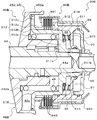
- FIG. 2 is an enlarged partial cross-sectional view showing a main part of the power transmission device 20.
- the secondary piston 51 constituting the second hydraulic actuator 48 of the CVT 40 is fitted to the secondary shaft 44 and extends in the axial direction of the secondary shaft 44, and the secondary pulley of the inner cylinder portion 511.
- a pressure receiving portion 512 extending outward from one end 511a on the 45 side, and an outer portion extending in the axial direction of the secondary shaft 44 so as to be separated from the secondary pulley 45 toward the opposite side of the secondary pulley 45 from the outer peripheral portion of the pressure receiving portion 512.
- a cylindrical member having a cylindrical part (drum part) 513 is configured.
- the inner cylinder portion 511 of the secondary piston 51 has a spline that can be engaged with a spline formed on the outer peripheral surface of the secondary shaft 44 on at least a part of the inner peripheral surface.
- the pressure receiving portion 512 includes a first pressure receiving portion 512a extending from the one end 511a of the inner cylinder portion 511 to the radially outer side of the secondary shaft 44, and an axial direction of the secondary shaft 44 from the outer peripheral portion of the first pressure receiving portion 512a toward the secondary pulley 45. And a second pressure receiving portion 512c extending outward in the radial direction of the secondary shaft 44 from one end on the secondary pulley 45 side of the axial extension portion 512b.
- the secondary piston 51 has an end 511 a on the secondary pulley 45 side of the inner cylinder portion 511 that abuts on a stepped portion 44 a formed on the secondary shaft 44, and a spline and a secondary shaft formed on the inner peripheral surface of the inner cylinder portion 511.
- the splines formed on the outer peripheral surface of 44 are fitted to the secondary shaft 44 so as to engage with each other. Thereby, the secondary piston 51 can rotate integrally with the secondary shaft 44.
- a screw portion is formed on the outer peripheral surface of the secondary shaft 44 so as to be positioned in the vicinity of the other end 511b of the inner cylinder portion 511 in a state where the inner cylinder portion 511 of the secondary piston 51 is fitted.
- a nut 55 is screwed into the threaded portion so as to come into contact with the other end 511b of the inner tube portion 511. Accordingly, the movement of the secondary piston 51 in the axial direction of the secondary shaft 44 can be more reliably regulated by the step portion 44a and the nut 55.
- a cylindrical extension 452a extending in the axial direction toward the opposite side to the fixed sheave 451 (the right side in the figure, that is, the counter drive gear 71 side) is formed.
- the movable sheave 452 is movably supported by the secondary shaft 44 so that the inner peripheral surface of the cylindrical extending portion 452a and the outer cylindrical portion 513 of the secondary piston 51 are in sliding contact with each other via a seal member.
- the movable sheave 452 and the secondary piston 51 define the oil chamber 48c, and the oil pressure adjusted by the hydraulic control device is supplied to the oil chamber 48c through the oil passage formed in the secondary shaft 44.
- the movable sheave 452 can be moved in the axial direction of the secondary shaft 44.
- the return spring 49 is disposed between the first pressure receiving portion 512 a of the secondary piston 51 and the contact portion 452 b formed on the movable sheave 452, and the return spring 49 attaches the movable sheave 452 to the fixed sheave 451. Energize to the side. As a result, even if hydraulic pressure is no longer supplied from the hydraulic control device to the second hydraulic actuator 48 when the vehicle is towed, the operation of the oil pump 30 is stopped when the engine is stopped, the secondary pulley is driven by the return spring 49. The movement of the movable sheave 452 can be restricted by urging the 45 movable sheaves 452 toward the fixed sheave 451.
- the secondary piston 51 configured as described above is also used as a clutch drum of the hydraulic clutch 80.
- the hydraulic clutch 80 includes a clutch piston 81 disposed in a space between the inner cylinder portion 511 and the outer cylinder portion 513 of the secondary piston 51, a clutch hub 82 supported by the counter drive gear 71, and a secondary piston.
- a plurality of first clutch plates (separator plates) 83 whose outer peripheral portions are fitted to splines 513 s formed on the inner peripheral surface of 51 outer cylinder portion (drum portion) 513, and formed on the outer peripheral surface of clutch hub 82.
- the inner peripheral portion is fitted to the spline and a hydraulic multi-plate friction clutch including a plurality of second clutch plates (friction plates) 84 capable of friction engagement with a plurality of first clutch plates 83 is configured. .
- the clutch piston 81 is disposed between the inner cylinder part 511 and the outer cylinder part 513 of the secondary piston 51 so as to be movable in the axial direction of the secondary shaft 44. And between the inner peripheral part of the clutch piston 81 and the outer peripheral surface of the inner cylinder part 511 of the secondary piston 51, and between the outer peripheral part of the clutch piston 81 and the inner peripheral surface of the outer cylinder part 513 of the secondary piston 51, Each of the seal members is arranged, whereby the clutch piston 81 and the secondary piston 51 define an engagement side oil chamber 87. That is, the secondary piston 51 constituting the second hydraulic actuator 48 is used as a clutch drum of the hydraulic clutch 80 and is used to define the engagement side oil chamber 87 of the hydraulic clutch 80.
- the clutch hub 82 extends between the cylindrical portion 821 to which the second clutch plate 84 is spline-fitted, a base end portion 822 supported by the counter drive gear 71, and the cylindrical portion 821 and the base end portion 822. An intermediate portion 823.
- the clutch hub 82 is disposed such that the cylindrical portion 821 is positioned between the inner cylindrical portion 511 and the outer cylindrical portion 513 of the secondary piston 51, and the base end portion 822 of the clutch hub 82 is the secondary end of the counter drive gear 71. It is connected (fixed) to one end on the pulley 45 side via a spline. As a result, the clutch hub 82 and the counter drive gear 71 can rotate together.
- a spacer 56 is disposed between one end portion of the counter drive gear 71 to which the base end portion 822 of the clutch hub 82 is coupled and the nut 55.
- a cancel oil chamber 88 is formed together with the clutch piston 81 for canceling the centrifugal hydraulic pressure generated in the secondary piston 51, that is, the engagement side oil chamber 87.
- a cancel plate 85 is arranged.
- Cancel plate 85 has an inner peripheral portion that is fitted to inner cylinder portion 511 of secondary piston 51 and an outer peripheral portion that is in sliding contact with the inner peripheral surface of clutch piston 81 via a seal member.
- a return spring 86 is disposed between the clutch piston 81 and the cancel plate 85, and movement of the cancel plate 85 in the axial direction is restricted by a snap ring attached to the inner cylinder portion 511 of the secondary piston 51. .
- the secondary piston 51 constituting the second hydraulic actuator 48 of the CVT 40 is also used as the clutch drum of the hydraulic clutch 80, thereby increasing the axial length associated with providing a dedicated clutch drum for the hydraulic clutch 80. Can be suppressed.
- a part of the clutch piston 81 and the clutch hub 82 (cylindrical portion 821), which are each constituent member of the hydraulic clutch 80 a cancel plate 85.
- the engagement-side oil chamber 87 and the cancel of the hydraulic clutch 80 are canceled.
- the oil chamber 88 is supplied with the hydraulic pressure adjusted by the hydraulic control device through the oil passages formed in the secondary shaft 44 and the secondary piston 51, respectively.
- the clutch piston 81 receiving the hydraulic pressure moves toward the first and second clutch plates 83, 84, and the clutch piston 81 and the secondary piston 51 (outside)
- the first and second clutch plates 83 and 84 are sandwiched between the abutting member fixed to the cylindrical portion 513).
- the hydraulic clutch 80 is engaged (completely engaged), and the secondary piston 51 and the clutch hub 82 are connected by the frictional force acting between the first and second clutch plates 83 and 84.
- the secondary shaft 44 of the CVT 40 integrated with the secondary piston 51 and the counter drive gear 71 connected to the clutch hub 82, that is, the axle 79 are connected.
- the power from the engine can be changed by the CVT 40 and transmitted to the left and right drive wheels via the gear mechanism 70, the differential gear 78, and the axle 79.
- hydraulic oil is not supplied from the oil pump 30 to the hydraulic control device when the engine is stopped, and hydraulic pressure is supplied from the hydraulic control device to the engagement side oil chamber 87 of the hydraulic clutch 80. Disappear.
- the hydraulic clutch 80 releases the connection between the secondary shaft 44 of the CVT 40 integrated with the secondary piston 51 and the counter drive gear 71 connected to the clutch hub 82, whereby the secondary shaft 44 of the CVT 40 The connection with the axle 79 is released.
- the power transmission device 20 includes the hydraulic clutch 80 that connects the secondary shaft 44 of the CVT 40 and the axle 79 and releases the connection therebetween, and the secondary pulley 45 of the CVT 40 includes the secondary shaft 45.
- the movable sheave 452 that is movably supported by the shaft 44, and the secondary piston 51 that rotates together with the secondary shaft 44 and forms the second hydraulic actuator 48 together with the movable sheave 452.
- the gear ratio of the CVT 40 is set to the maximum deceleration side in a state where the connection between the secondary shaft 44 of the CVT 40 and the axle 79 is released by the hydraulic clutch 80 immediately before the vehicle stops or while the vehicle stops.
- the belt return control to be transferred can be executed, it is possible to suppress an increase in size of the oil pump 30 that generates the hydraulic pressure supplied to the first and second hydraulic actuators 47 and 48 of the CVT 40.
- the secondary piston 51 constituting the second hydraulic actuator 48 is used to define the engagement side oil chamber 87 of the hydraulic clutch 80 as described above, the hydraulic clutch It is possible to suppress an increase in axial length due to the provision of a dedicated member for defining the engagement side oil chamber 87 at 80. As a result, in the power transmission device 20, it is possible to better suppress the increase in size of the device while enabling the connection between the CVT 40 and the axle 79 to be released.
- a return spring 49 that biases the movable sheave 452 toward the fixed sheave side of the secondary pulley 45 is disposed.
- the hydraulic oil is not supplied from the oil pump 30 to the hydraulic control device in accordance with the stoppage of the engine, and the hydraulic control is performed on the engagement side oil chamber 87 of the hydraulic clutch 80. Since the hydraulic pressure is not supplied from the apparatus, the hydraulic clutch 80 releases the connection between the secondary shaft 44 of the CVT 40 and the axle 79. For this reason, the inertia from the axle 79 side is not transmitted to the secondary pulley 45 provided on the secondary shaft 44 of the CVT 40, so that the torque generated in the movable sheave 452 due to the inertia from the axle 79 side needs to be held by the return spring 49. Disappear.
- the second hydraulic actuator 48 can be made compact.
- the secondary piston 51 of the second hydraulic actuator 48 includes an inner cylinder part 511 fitted to the secondary shaft 44, a pressure receiving part 512 extending outward from one end 511a on the secondary pulley 45 side of the inner cylinder part 511, and a pressure receiving part.
- the outer cylinder portion 513 extends from the outer peripheral portion of the 512 to the opposite side of the secondary pulley 45.
- the hydraulic clutch 80 includes a clutch piston 81 disposed between the inner cylinder part 511 and the outer cylinder part 513, and at least a part (cylindrical part 821) of the inner cylinder part 511 and the outer cylinder part 513.
- the clutch hub 82 disposed between the plurality of first clutch plates 83 fitted to the outer cylinder portion 513, and fitted to the clutch hub 82 and capable of frictional engagement with the plurality of first clutch plates 83.
- the secondary piston 51 (outer cylinder portion 513) of the second hydraulic actuator 48 can also be used as a clutch drum of the hydraulic clutch 80, so that the shaft associated with the provision of a dedicated clutch drum in the hydraulic clutch 80. An increase in length can be suppressed.
- the constituent members of the hydraulic clutch 80 in the space between the inner cylinder portion 511 and the outer cylinder portion 513 of the secondary piston 51 constituting the second hydraulic actuator 48, the installation of the hydraulic clutch 80 is performed. It becomes possible to suppress the increase of the axial length of the power transmission device 20 accompanying it more favorably.
- the secondary piston 51 of the second hydraulic actuator 48 includes a stepped portion 44 a formed on the secondary shaft 44 so as to abut on one end 511 a of the inner cylinder portion 511, and the secondary shaft 44 on the other end 511 b side of the inner cylinder portion 511. And is held by a nut 55 that is screwed together. Thereby, the movement in the axial direction of the secondary piston 51 of the second hydraulic actuator 48 can be more reliably regulated.
- the power transmission device 20 of the above embodiment omits forming the cancel oil chamber on the back side of the secondary piston 51 for canceling the centrifugal hydraulic pressure generated in the oil chamber of the second hydraulic actuator 48 of the CVT 40. It can also be said that this corresponds to a configuration in which the hydraulic clutch 80 is disposed in a space where the cancel oil chamber is omitted. Therefore, it is preferable that the power transmission device 20 described above is configured to include a CVT 40 having a relatively small capacity. However, it goes without saying that a cancel oil chamber may be formed in the second hydraulic actuator 48 of the CVT 40.
- the secondary piston 51 is comprised by integrally forming the inner cylinder part 511, the pressure receiving part 512, and the outer cylinder part 513, it is not restricted to this. That is, the secondary piston 51 integrally forms the inner cylinder portion 511 and the pressure receiving portion 512 and at the same time (for example, the outer peripheral portion) of the separate outer cylinder portion 513 that functions as a clutch drum of the hydraulic clutch 80. You may comprise by fixing to.
- FIG. 3 is an enlarged partial sectional view showing a main part of a power transmission device 20B according to another embodiment of the present invention.
- the same referential mark is attached
- the secondary piston 51 ⁇ / b> B constituting the second hydraulic actuator 48 ⁇ / b> B of the CVT 40 ⁇ / b> B is fitted to the secondary shaft 44 and extends in the axial direction of the secondary shaft 44, as illustrated.
- the inner cylindrical portion 511 is configured as a cylindrical member having a pressure receiving portion 512 extending from one end 511 a on the secondary pulley 45 (movable sheave 452) side toward the outside of the secondary shaft 44.
- the pressure receiving portion 512 of the secondary piston 51B includes a first pressure receiving portion 512a extending from the one end 511a of the inner cylinder portion 511 to the radially outer side of the secondary shaft 44, and a secondary pulley 45 (movable sheave 452) from the outer peripheral portion of the first pressure receiving portion 512a.
- a cylindrical axially extending portion 512b extending in the axial direction of the secondary shaft 44 toward the end, and extending radially outwardly of the secondary shaft 44 from one end of the axially extending portion 512b on the secondary pulley 45 (movable sheave 452) side. 2nd pressure receiving part 512c.
- a spline 512s is formed on the outer peripheral surface of the axially extending portion 512b of the pressure receiving portion 512 so as to be close to the second pressure receiving portion 512c, and is close to the first pressure receiving portion 512a of the axially extending portion 512b.
- the outer peripheral surface is a smooth cylindrical surface having a smaller diameter than the tip circle of the spline 512s.
- one end 511a of the inner cylinder portion 511 on the secondary pulley 45 (movable sheave 452) side abuts on a stepped portion 44a formed on the secondary shaft 44, and the cylinder of the movable sheave 452 supported by the secondary shaft 44.
- the secondary shaft 44 is fitted (spline fitted) so that the inner peripheral surface of the elongated portion 452a and the outer peripheral surface of the second pressure receiving portion 512c are in sliding contact with each other via a seal member.
- the movable sheave 452 and the secondary piston 51B define the oil chamber 48c.
- a return spring 49 that urges the movable sheave 452 toward the fixed sheave 45 is disposed between the pressure receiving portion 512 (first pressure receiving portion 512a) of the secondary piston 51B and the contact portion 452b of the movable sheave 452. .
- the return spring 49 causes the secondary pulley to The movement of the movable sheave 452 can be restricted by urging the 45 movable sheaves 452 toward the fixed sheave.
- the secondary piston 51B configured as described above, that is, the axially extending portion 512b of the pressure receiving portion 512 having the spline 512s is also used as a clutch hub of the hydraulic clutch 80.
- the hydraulic clutch 80B includes a clutch piston 81B that is fitted to the inner cylindrical portion 511 of the secondary piston 51B and is supported by the secondary piston 51B so as to be movable in the axial direction, and a clutch drum 89 that is supported by the counter drive gear.
- a plurality of first clutch plates (friction plates) 83B whose inner peripheral portions are fitted to splines 512s formed on the outer peripheral surface of the axially extending portion 512b of the pressure receiving portion 512, and the inner peripheral surface of the clutch drum 89
- the outer peripheral portion is fitted to the splines formed in the first and second clutch plates 81B, and the engagement side oil chamber 87 together with the clutch pistons 81B.
- a hydraulic multi-plate friction clutch including an oil chamber defining member 90 that defines .
- Clutch piston 81B extends from the outer periphery of pressure receiving portion 810 in a direction away from the movable sheave 452 of CVT 40 (right side in FIG. 3), and annular pressure receiving portion 810 fitted to inner cylinder portion 511 of secondary piston 51B.
- the outer peripheral portion of the pressure receiving portion 810 so that the first cylindrical portion 811 defining the engagement side oil chamber 87 together with the oil chamber defining member 90 and the first and second clutch plates 83B and 84B can be pressed.
- a second cylindrical portion 812 extending toward the movable sheave 452 of the CVT 40.
- the inner peripheral surface of the pressure receiving portion 810 is in sliding contact with the outer peripheral surface of the inner cylindrical portion 511 of the secondary piston 51B, and the inner peripheral surface of the second cylindrical portion 812 is the axially extending portion 512b of the secondary piston 51B.
- the inner cylinder portion 511 is fitted so as to be in sliding contact with the outer peripheral surface on the first pressure receiving portion 512a side.
- a seal member is provided between the inner peripheral surface of the pressure receiving portion 810 and the outer peripheral surface of the inner cylindrical portion 511 and between the inner peripheral surface of the second cylindrical portion 812 and the outer peripheral surface of the axially extending portion 512b.
- the clutch piston 81B defines a cancel oil chamber 88 together with the first pressure receiving portion 512a of the secondary piston 51B. That is, the secondary piston 51 ⁇ / b> B constituting the second hydraulic actuator 48 is also used as a clutch hub of the hydraulic clutch 80 and is used to define a cancel oil chamber 88 of the hydraulic clutch 80.
- the clutch drum 89 includes a cylindrical portion 891 to which the second clutch plate 84B is spline-fitted, a base end portion (not shown) supported by the counter drive gear, and an intermediate portion extending between the cylindrical portion 891 and the base end portion. Part 893.
- the clutch drum 89 is disposed so that the cylindrical portion 891 surrounds the spline 512s formed in the axially extending portion 512b of the secondary piston 51B, and the base end portion of the clutch drum 89 is the secondary pulley 45 ( It is connected to one end of the movable sheave 452) via a spline.
- the clutch drum 89 and the counter drive gear can rotate together.
- the oil chamber defining member 90 of the hydraulic clutch 80 is configured as a bottomed cylindrical annular member, and has a central hole into which the secondary shaft 44 is fitted, and a short length extending in the axial direction from the outer peripheral portion. A cylindrical portion.
- the oil chamber defining member 90 is in contact with the other end 511b of the inner cylindrical portion 511 of the secondary piston 51B, and the outer peripheral surface of the cylindrical portion is in sliding contact with the inner peripheral surface of the first cylindrical portion 811 of the clutch piston 81B. Is fitted to the secondary shaft 44. Further, a seal member is disposed between the outer peripheral surface of the cylindrical portion of the oil chamber defining member 90 and the inner peripheral surface of the first cylindrical portion 811.
- a screw portion is formed on the outer peripheral surface of the secondary shaft 44 so as to be positioned in the vicinity of the other end 511b of the inner cylinder portion 511 in a state where the inner cylinder portion 511 of the secondary piston 51B is fitted.
- a nut 55 is screwed into the threaded portion so as to contact the oil chamber defining member 90.
- the secondary piston 51 and the oil chamber defining member 90 are formed by the stepped portion 44a provided on the one end 511a side of the inner cylinder portion 511 and the nut 55 screwed to the secondary shaft 44 on the other end 511b side of the secondary piston 51B. The movement in the axial direction can be more reliably regulated.
- the transmission ratio of the CVT 40B is released in a state where the connection between the secondary shaft 44 of the CVT 40B and the axle 79 is released by the hydraulic clutch 80B immediately before the vehicle stops or during the vehicle stop. Since the belt return control for shifting the engine to the most deceleration side can be executed, it is possible to suppress an increase in the size of the oil pump that generates the hydraulic pressure supplied to the first and second hydraulic actuators 47 and 48B of the CVT 40B. Become. Further, the secondary piston 51B constituting the second hydraulic actuator 48B of the CVT 40B is used to define the cancel oil chamber 88 of the hydraulic clutch 80B, thereby defining the cancel oil chamber 88 in the hydraulic clutch 80B. An increase in the axial length associated with the provision of a dedicated member can be suppressed. Therefore, also in the power transmission device 20B, the enlargement of the device can be better suppressed while the connection between the CVT 40 and the axle 79 can be released.
- a return spring 49 that biases the movable sheave 452 toward the fixed sheave side of the secondary pulley 45 is disposed.
- a compact spring having a relatively small spring constant can be employed as the return spring 49 that holds the movable sheave 452 of the secondary pulley 45. 2
- the hydraulic actuator 48B can be made compact, and it is possible to more easily secure a space for disposing the constituent members of the hydraulic clutch 80B.
- the secondary piston 51B of the second hydraulic actuator 48B extends outward from the inner cylinder portion 511 fitted to the secondary shaft 44 and the one end 511a of the inner cylinder portion 511 on the secondary pulley 45 (movable sheave 452) side.
- a pressure receiving portion 512 including an axially extending portion 512b as a cylindrical hub portion having splines 512s.
- the hydraulic clutch 80B is fitted to the inner cylinder portion 511 and at least partly (a cylindrical portion 891), a clutch piston 81B that defines the cancel oil chamber 88 together with the first pressure receiving portion 512a of the pressure receiving portion 512.
- a clutch drum 89 disposed so as to surround the axially extending portion 512b (hub portion) of the pressure receiving portion 512, and a plurality of first clutch plates 83B fitted to the axially extending portion 512b of the pressure receiving portion 512.
- a second clutch plate 84B that is fitted to the cylindrical portion 891 of the clutch drum 89 and frictionally engageable with the first clutch plate 83B.
- the secondary piston 51B of the second hydraulic actuator 48B can also be used as a clutch hub of the hydraulic clutch 80B, so that an increase in shaft length due to the provision of a dedicated clutch hub in the hydraulic clutch 80B is suppressed. It becomes possible.
- the secondary piston 51B of the second hydraulic actuator 48B also has a stepped portion 44a formed on the secondary shaft 44 so as to come into contact with the one end 511a of the inner cylinder portion 511, and the secondary shaft 44 on the other end 511b side of the inner cylinder portion 511. And is held by a nut 55 that is screwed together. Thereby, the movement in the axial direction of the secondary piston 51B of the second hydraulic actuator 48B can be more reliably regulated.
- a cancel oil chamber may be provided in the second hydraulic actuator 48B of the CVT 40B.
- the secondary piston 51 is formed by integrally forming the inner cylinder portion 511 and the pressure receiving portion 512, and a separate cylindrical member (hub portion) that functions as a clutch hub of the hydraulic clutch 80. It may be configured to be fixed at an appropriate place (for example, the second pressure receiving portion 512c or the like).
- the primary pulley 43 that is provided on the primary shaft 42 that is connected to the vehicle engine and the groove width can be changed, and the secondary shaft 44 that is connected to the vehicle axle 79 and the groove width are provided.
- the CVT 40, 40B including the second hydraulic actuators 48, 48B to be changed corresponds to a “continuously variable transmission”, and the oil pump 30 for generating the hydraulic pressure supplied to the first and second hydraulic actuators 47, 48, 48B is provided.
- the hydraulic clutches 80 and 80B that connect the shaft 44 and the axle 79 and release the connection therebetween correspond to “hydraulic clutches”, and the movable sheave 452 that is movably supported by the secondary shaft 44 is “movable sheave”.
- the secondary pistons 51 and 51B that rotate integrally with the secondary shaft 44 and constitute the second hydraulic actuator 48 together with the movable sheave 452 of the secondary pulley 45 correspond to the “piston”.
- the present invention can be used in the power transmission device manufacturing industry and the like.
Abstract
Description
車両の原動機に連結される駆動側回転軸に設けられると共に溝幅を変更可能な第1プーリと、前記車両の車軸に連結される従動側回転軸に設けられると共に溝幅を変更可能な第2プーリと、前記第1および第2プーリに架け渡されるベルトと、前記第1プーリの前記溝幅を変更する第1油圧アクチュエータと、前記第2プーリの前記溝幅を変更する第2油圧アクチュエータとを含む無段変速機と、前記第1および第2油圧アクチュエータに供給される油圧を発生するオイルポンプとを含む動力伝達装置であって、
前記無段変速機の前記従動側回転軸と前記車軸とを連結すると共に両者の連結を解除する油圧式クラッチを備え、
前記無段変速機の前記第2プーリは、前記従動側回転軸により移動自在に支持される可動シーブと、前記従動側回転軸と一体に回転して前記可動シーブと共に前記第2油圧アクチュエータを構成するピストンとを有し、
前記第2油圧アクチュエータの前記ピストンは、前記油圧式クラッチの係合側油室を画成するのに用いられることを特徴とする。
車両の原動機に連結される駆動側回転軸に設けられると共に溝幅を変更可能な第1プーリと、前記車両の車軸に連結される従動側回転軸に設けられると共に溝幅を変更可能な第2プーリと、前記第1および第2プーリに架け渡されるベルトと、前記第1プーリの前記溝幅を変更する第1油圧アクチュエータと、前記第2プーリの前記溝幅を変更する第2油圧アクチュエータとを含む無段変速機と、前記第1および第2油圧アクチュエータに供給される油圧を発生するオイルポンプとを含む動力伝達装置であって、
前記無段変速機の前記従動側回転軸と前記車軸とを連結すると共に両者の連結を解除する油圧式クラッチを備え、
前記無段変速機の前記第2プーリは、前記従動側回転軸により移動自在に支持される可動シーブと、前記従動側回転軸と一体に回転して前記可動シーブと共に前記第2油圧アクチュエータを構成するピストンとを有し、
前記第2油圧アクチュエータの前記ピストンは、前記油圧式クラッチの係合側油室で発生する遠心油圧をキャンセルするためのキャンセル油室を画成するのに用いられることを特徴とする。
Claims (8)
- 車両の原動機に連結される駆動側回転軸に設けられると共に溝幅を変更可能な第1プーリと、前記車両の車軸に連結される従動側回転軸に設けられると共に溝幅を変更可能な第2プーリと、前記第1および第2プーリに架け渡されるベルトと、前記第1プーリの前記溝幅を変更する第1油圧アクチュエータと、前記第2プーリの前記溝幅を変更する第2油圧アクチュエータとを含む無段変速機と、前記第1および第2油圧アクチュエータに供給される油圧を発生するオイルポンプとを含む動力伝達装置であって、
前記無段変速機の前記従動側回転軸と前記車軸とを連結すると共に両者の連結を解除する油圧式クラッチを備え、
前記無段変速機の前記第2プーリは、前記従動側回転軸により移動自在に支持される可動シーブと、前記従動側回転軸と一体に回転して前記可動シーブと共に前記第2油圧アクチュエータを構成するピストンとを有し、
前記第2油圧アクチュエータの前記ピストンは、前記油圧式クラッチの係合側油室を画成するのに用いられることを特徴とする動力伝達装置。 - 前記第2プーリの前記可動シーブと前記第2油圧アクチュエータの前記ピストンとの間には、前記可動シーブを前記第2プーリの固定シーブ側に付勢するリターンスプリングが配置されることを特徴とする請求項1に記載の動力伝達装置。
- 前記第2油圧アクチュエータの前記ピストンは、前記従動側回転軸に嵌合される内筒部と、該内筒部の前記第2プーリ側の一端から外側に延びる受圧部と、該受圧部の外周部から前記第2プーリとは反対側に延びる外筒部とを有し、
前記油圧式クラッチは、前記内筒部と前記外筒部との間に配置されるクラッチピストンと、少なくとも一部が前記内筒部および前記外筒部との間に配置されるクラッチハブと、前記外筒部に嵌合される第1クラッチプレートと、前記クラッチハブに嵌合されると共に前記第1クラッチプレートと摩擦係合可能な第2クラッチプレートとを有することを特徴とする請求項1または2に記載の動力伝達装置。 - 前記第2油圧アクチュエータの前記ピストンは、前記内筒部の前記一端と当接するように前記従動側回転軸に形成された段部と、前記内筒部の他端側で前記従動側回転軸に螺合されるナットとにより保持されることを特徴とする請求項3に記載の動力伝達装置。
- 車両の原動機に連結される駆動側回転軸に設けられると共に溝幅を変更可能な第1プーリと、前記車両の車軸に連結される従動側回転軸に設けられると共に溝幅を変更可能な第2プーリと、前記第1および第2プーリに架け渡されるベルトと、前記第1プーリの前記溝幅を変更する第1油圧アクチュエータと、前記第2プーリの前記溝幅を変更する第2油圧アクチュエータとを含む無段変速機と、前記第1および第2油圧アクチュエータに供給される油圧を発生するオイルポンプとを含む動力伝達装置であって、
前記無段変速機の前記従動側回転軸と前記車軸とを連結すると共に両者の連結を解除する油圧式クラッチを備え、
前記無段変速機の前記第2プーリは、前記従動側回転軸により移動自在に支持される可動シーブと、前記従動側回転軸と一体に回転して前記可動シーブと共に前記第2油圧アクチュエータを構成するピストンとを有し、
前記第2油圧アクチュエータの前記ピストンは、前記油圧式クラッチの係合側油室で発生する遠心油圧をキャンセルするためのキャンセル油室を画成するのに用いられることを特徴とする動力伝達装置。 - 前記第2プーリの前記可動シーブと前記第2油圧アクチュエータの前記ピストンとの間には、前記可動シーブを前記第2プーリの固定シーブ側に付勢するリターンスプリングが配置されることを特徴とする請求項5に記載の動力伝達装置。
- 前記第2油圧アクチュエータの前記ピストンは、前記従動側回転軸に嵌合される内筒部と、該内筒部の前記第2プーリ側の一端から外側に延びると共に筒状のハブ部を含む受圧部とを有し、
前記油圧式クラッチは、前記内筒部に嵌合されると共に前記受圧部と共に前記キャンセル油室を画成するクラッチピストンと、少なくとも一部が前記受圧部の前記ハブ部を囲むように配置されるクラッチドラムと、前記受圧部の前記ハブ部に嵌合される第1クラッチプレートと、前記クラッチドラムに嵌合されると共に前記第1クラッチプレートと摩擦係合可能な第2クラッチプレートとを有することを特徴とする請求項5または6に記載の動力伝達装置。 - 前記第2油圧アクチュエータの前記ピストンは、前記内筒部の前記一端と当接するように前記従動側回転軸に形成された段部と、前記内筒部の他端側で前記従動側回転軸に螺合されるナットとにより保持されることを特徴とする請求項7に記載の動力伝達装置。
Priority Applications (5)
| Application Number | Priority Date | Filing Date | Title |
|---|---|---|---|
| US14/761,501 US9689440B2 (en) | 2013-02-14 | 2014-02-14 | Power transfer device |
| JP2015500312A JP6217740B2 (ja) | 2013-02-14 | 2014-02-14 | 動力伝達装置 |
| EP14752134.8A EP2916039A4 (en) | 2013-02-14 | 2014-02-14 | POWER TRANSMISSION DEVICE |
| CN201480004917.7A CN104919214B (zh) | 2013-02-14 | 2014-02-14 | 动力传递装置 |
| KR1020157018872A KR101713468B1 (ko) | 2013-02-14 | 2014-02-14 | 동력 전달 장치 |
Applications Claiming Priority (2)
| Application Number | Priority Date | Filing Date | Title |
|---|---|---|---|
| JP2013026481 | 2013-02-14 | ||
| JP2013-026481 | 2013-02-14 |
Publications (1)
| Publication Number | Publication Date |
|---|---|
| WO2014126205A1 true WO2014126205A1 (ja) | 2014-08-21 |
Family
ID=51354204
Family Applications (1)
| Application Number | Title | Priority Date | Filing Date |
|---|---|---|---|
| PCT/JP2014/053489 WO2014126205A1 (ja) | 2013-02-14 | 2014-02-14 | 動力伝達装置 |
Country Status (6)
| Country | Link |
|---|---|
| US (1) | US9689440B2 (ja) |
| EP (1) | EP2916039A4 (ja) |
| JP (1) | JP6217740B2 (ja) |
| KR (1) | KR101713468B1 (ja) |
| CN (1) | CN104919214B (ja) |
| WO (1) | WO2014126205A1 (ja) |
Families Citing this family (6)
| Publication number | Priority date | Publication date | Assignee | Title |
|---|---|---|---|---|
| ITUB20152255A1 (it) * | 2015-07-17 | 2017-01-17 | Omsi Trasmissioni S P A | Gruppo frizione per presa di forza |
| JP6509933B2 (ja) * | 2017-03-15 | 2019-05-08 | 本田技研工業株式会社 | 動力伝達装置 |
| EP3927999A1 (en) | 2019-02-20 | 2021-12-29 | TEAM Industries, Inc. | Drivetrain layout with cvt |
| US11543006B2 (en) | 2019-06-21 | 2023-01-03 | Team Industries, Inc. | Variable torque limiting clutch for a steel belt continuously variable transmission |
| US11499608B2 (en) * | 2019-06-21 | 2022-11-15 | Team Industries, Inc. | Integrated launch clutch and drive sheave for steel belt continuously variable transmission |
| US20230279925A1 (en) * | 2022-03-07 | 2023-09-07 | Team Industries, Inc. | Continuously variable transmission clutch with a peak torque limiter |
Citations (6)
| Publication number | Priority date | Publication date | Assignee | Title |
|---|---|---|---|---|
| JPH08210382A (ja) * | 1995-10-20 | 1996-08-20 | Honda Motor Co Ltd | 無段変速機を備えた動力伝達装置 |
| JP2005170233A (ja) | 2003-12-11 | 2005-06-30 | Nissan Motor Co Ltd | 車両の制御装置及び制御方法 |
| JP2006118688A (ja) * | 2004-10-25 | 2006-05-11 | Toyota Motor Corp | ベルト式無段変速機 |
| JP2010071453A (ja) * | 2008-09-22 | 2010-04-02 | Toyota Motor Corp | ベルト式無段変速機のプーリ及びベルト式無段変速機 |
| JP2011122671A (ja) | 2009-12-10 | 2011-06-23 | Toyota Motor Corp | 車両用動力伝達装置 |
| JP2012036969A (ja) * | 2010-08-06 | 2012-02-23 | Toyota Motor Corp | 車両用駆動装置 |
Family Cites Families (37)
| Publication number | Priority date | Publication date | Assignee | Title |
|---|---|---|---|---|
| US3044316A (en) * | 1955-01-07 | 1962-07-17 | Lloyd M Forster | Continuously variable transmission and automatic control |
| JPS5747059A (en) * | 1980-09-04 | 1982-03-17 | Aisin Warner Ltd | Torque ratio detecting mechanism of v belt type stepless transmission gear |
| NL186266C (nl) * | 1982-03-10 | 1990-10-16 | Honda Motor Co Ltd | Overbrenging voor een motorvoertuig. |
| US4583423A (en) * | 1983-02-24 | 1986-04-22 | Ford Motor Company | Infinitely variable transmission for automotive vehicle driveline |
| US4747808A (en) * | 1987-01-08 | 1988-05-31 | Ford Motor Company | System for actuating the displaceable pulley in a continually variable transmission |
| JP2790627B2 (ja) * | 1987-04-30 | 1998-08-27 | 本田技研工業株式会社 | ベルト無段変速機の制御方法および制御装置 |
| JPS63280955A (ja) * | 1987-05-12 | 1988-11-17 | Honda Motor Co Ltd | 無段変速機の変速比制御方法および変速比制御装置 |
| JPH02107859A (ja) * | 1988-07-07 | 1990-04-19 | Toyota Motor Corp | 遊星歯車装置 |
| JP2687041B2 (ja) * | 1990-10-29 | 1997-12-08 | 本田技研工業株式会社 | ベルト式無段変速機 |
| US5407394A (en) * | 1993-05-05 | 1995-04-18 | Borg-Warner Automotive, Inc. | Guide for an adjustable pulley in a continuously variable transmission |
| BE1008501A3 (nl) | 1994-07-13 | 1996-05-07 | Vcst Nv | Transmissie-eenheid voor motorvoertuigen. |
| JPH08285021A (ja) * | 1995-04-10 | 1996-11-01 | Unisia Jecs Corp | 無段変速機の制御装置 |
| JP3623337B2 (ja) * | 1997-03-14 | 2005-02-23 | ジヤトコ株式会社 | 変速機内の締結要素への作動流体路構造 |
| JP3913849B2 (ja) * | 1997-08-04 | 2007-05-09 | 本田技研工業株式会社 | 金属vベルト式無段変速機 |
| JP2000220721A (ja) * | 1999-01-29 | 2000-08-08 | Suzuki Motor Corp | 無段変速機 |
| JP4472077B2 (ja) * | 1999-11-13 | 2010-06-02 | 東京自動機工株式会社 | 無段可変伝動機 |
| JP3461329B2 (ja) * | 2000-07-05 | 2003-10-27 | 本田技研工業株式会社 | 無段変速機の油圧制御装置 |
| JP3469182B2 (ja) * | 2000-09-05 | 2003-11-25 | 本田技研工業株式会社 | 車両用無段変速機の制御装置 |
| GB2368102B (en) * | 2000-10-19 | 2005-03-09 | Gen Motors Corp | Transmission decoupling device |
| JP2002295613A (ja) * | 2001-03-30 | 2002-10-09 | Honda Motor Co Ltd | ベルト式無段変速機 |
| JP3657892B2 (ja) * | 2001-06-12 | 2005-06-08 | 本田技研工業株式会社 | 自動変速機の制御装置 |
| CN1932260B (zh) * | 2002-04-08 | 2011-06-08 | 雅马哈发动机株式会社 | 发动机 |
| JP2004019830A (ja) * | 2002-06-18 | 2004-01-22 | Toyota Motor Corp | 動力伝達断続装置 |
| ITTO20021088A1 (it) * | 2002-12-16 | 2004-06-17 | Piaggio & C Spa | Gruppo motopropulsore ibrido per un veicolo, particolarmente per uno scooter. |
| JP4288080B2 (ja) * | 2003-01-23 | 2009-07-01 | 本田技研工業株式会社 | ベルト式無段変速機 |
| JP2006342815A (ja) * | 2003-06-16 | 2006-12-21 | Yamaha Motor Co Ltd | Vベルト式無段変速装置内蔵エンジン |
| JP4449441B2 (ja) * | 2003-12-09 | 2010-04-14 | トヨタ自動車株式会社 | ベルト式無段変速機 |
| JP4274033B2 (ja) * | 2004-04-14 | 2009-06-03 | トヨタ自動車株式会社 | ベルト式無段変速機の制御装置 |
| JP4344379B2 (ja) * | 2006-12-06 | 2009-10-14 | ジヤトコ株式会社 | 無段変速機の制御装置 |
| JP4398974B2 (ja) * | 2006-12-28 | 2010-01-13 | 本田技研工業株式会社 | 自動二輪車 |
| US7862459B2 (en) * | 2007-03-20 | 2011-01-04 | Yamaha Hatsudoki Kabushiki Kaisha | Transmission, power unit having the same, vehicle, controller for transmission, and method of controlling transmission |
| JP2008274976A (ja) * | 2007-04-25 | 2008-11-13 | Honda Motor Co Ltd | 自動二輪車用パワーユニット |
| JP2010203548A (ja) * | 2009-03-04 | 2010-09-16 | Toyota Motor Corp | ベルト式無段変速機 |
| JP4435860B1 (ja) * | 2009-04-30 | 2010-03-24 | ジヤトコ株式会社 | ベルト式無段変速機の制御装置と制御方法 |
| JP5342585B2 (ja) * | 2011-03-23 | 2013-11-13 | ジヤトコ株式会社 | ベルト式無段変速機 |
| JP5297493B2 (ja) * | 2011-04-11 | 2013-09-25 | 本田技研工業株式会社 | ベルト式無段変速機の制御装置 |
| JP5551212B2 (ja) * | 2012-06-20 | 2014-07-16 | ヤマハ発動機株式会社 | 鞍乗型車両 |
-
2014
- 2014-02-14 CN CN201480004917.7A patent/CN104919214B/zh active Active
- 2014-02-14 KR KR1020157018872A patent/KR101713468B1/ko not_active Application Discontinuation
- 2014-02-14 WO PCT/JP2014/053489 patent/WO2014126205A1/ja active Application Filing
- 2014-02-14 EP EP14752134.8A patent/EP2916039A4/en not_active Withdrawn
- 2014-02-14 US US14/761,501 patent/US9689440B2/en active Active
- 2014-02-14 JP JP2015500312A patent/JP6217740B2/ja not_active Expired - Fee Related
Patent Citations (6)
| Publication number | Priority date | Publication date | Assignee | Title |
|---|---|---|---|---|
| JPH08210382A (ja) * | 1995-10-20 | 1996-08-20 | Honda Motor Co Ltd | 無段変速機を備えた動力伝達装置 |
| JP2005170233A (ja) | 2003-12-11 | 2005-06-30 | Nissan Motor Co Ltd | 車両の制御装置及び制御方法 |
| JP2006118688A (ja) * | 2004-10-25 | 2006-05-11 | Toyota Motor Corp | ベルト式無段変速機 |
| JP2010071453A (ja) * | 2008-09-22 | 2010-04-02 | Toyota Motor Corp | ベルト式無段変速機のプーリ及びベルト式無段変速機 |
| JP2011122671A (ja) | 2009-12-10 | 2011-06-23 | Toyota Motor Corp | 車両用動力伝達装置 |
| JP2012036969A (ja) * | 2010-08-06 | 2012-02-23 | Toyota Motor Corp | 車両用駆動装置 |
Non-Patent Citations (1)
| Title |
|---|
| See also references of EP2916039A4 |
Also Published As
| Publication number | Publication date |
|---|---|
| US9689440B2 (en) | 2017-06-27 |
| KR101713468B1 (ko) | 2017-03-07 |
| EP2916039A1 (en) | 2015-09-09 |
| CN104919214B (zh) | 2018-04-06 |
| JP6217740B2 (ja) | 2017-10-25 |
| CN104919214A (zh) | 2015-09-16 |
| US20150345570A1 (en) | 2015-12-03 |
| EP2916039A4 (en) | 2016-04-13 |
| JPWO2014126205A1 (ja) | 2017-02-02 |
| KR20150096717A (ko) | 2015-08-25 |
Similar Documents
| Publication | Publication Date | Title |
|---|---|---|
| JP6217740B2 (ja) | 動力伝達装置 | |
| US9784345B2 (en) | Transmission device | |
| US7998011B2 (en) | Speed change apparatus | |
| US20090114501A1 (en) | Frictional engagement device | |
| US20190293129A1 (en) | Frictional coupling device of vehicular power transmitting system | |
| JP2009185928A (ja) | 摩擦係合装置 | |
| US8771131B2 (en) | Transmission device | |
| JP7040396B2 (ja) | 車両用動力伝達装置 | |
| JP2010242863A (ja) | ベルト式無段変速機 | |
| JPH0819996B2 (ja) | 車両用遊星歯車式自動変速機 | |
| JP6708102B2 (ja) | 車両用シンクロメッシュ機構の油圧装置 | |
| JP6359044B2 (ja) | 動力伝達機構 | |
| JP6229644B2 (ja) | 流体伝動装置 | |
| JP2010216613A (ja) | 車両用駆動装置 | |
| JP2007298139A (ja) | ベルト式無段変速機 | |
| JP4697082B2 (ja) | 自動変速機 | |
| US10907702B2 (en) | Transmission device | |
| JP6328178B2 (ja) | 変速ユニット | |
| JP6311580B2 (ja) | 流体伝動装置 | |
| WO2019167426A1 (ja) | 動力伝達装置 | |
| JP2021127808A (ja) | クラッチ機構 | |
| JPH10274320A (ja) | 車両用ベルト式変速装置 | |
| JP2020159499A (ja) | 摩擦係合装置および動力伝達装置 | |
| JP2016173119A (ja) | 動力伝達装置 | |
| JP2010014220A (ja) | スナップリングの脱落防止構造 |
Legal Events
| Date | Code | Title | Description |
|---|---|---|---|
| 121 | Ep: the epo has been informed by wipo that ep was designated in this application |
Ref document number: 14752134 Country of ref document: EP Kind code of ref document: A1 |
|
| WWE | Wipo information: entry into national phase |
Ref document number: 2014752134 Country of ref document: EP |
|
| ENP | Entry into the national phase |
Ref document number: 2015500312 Country of ref document: JP Kind code of ref document: A |
|
| ENP | Entry into the national phase |
Ref document number: 20157018872 Country of ref document: KR Kind code of ref document: A |
|
| WWE | Wipo information: entry into national phase |
Ref document number: 14761501 Country of ref document: US |
|
| NENP | Non-entry into the national phase |
Ref country code: DE |