WO2014002835A1 - Procédé de concentration de liquide de déchets de traitement et procédé de recyclage de liquide de déchets de traitement - Google Patents
Procédé de concentration de liquide de déchets de traitement et procédé de recyclage de liquide de déchets de traitement Download PDFInfo
- Publication number
- WO2014002835A1 WO2014002835A1 PCT/JP2013/066758 JP2013066758W WO2014002835A1 WO 2014002835 A1 WO2014002835 A1 WO 2014002835A1 JP 2013066758 W JP2013066758 W JP 2013066758W WO 2014002835 A1 WO2014002835 A1 WO 2014002835A1
- Authority
- WO
- WIPO (PCT)
- Prior art keywords
- group
- mass
- waste liquid
- lithographic printing
- general formula
- Prior art date
Links
Images
Classifications
-
- G—PHYSICS
- G03—PHOTOGRAPHY; CINEMATOGRAPHY; ANALOGOUS TECHNIQUES USING WAVES OTHER THAN OPTICAL WAVES; ELECTROGRAPHY; HOLOGRAPHY
- G03F—PHOTOMECHANICAL PRODUCTION OF TEXTURED OR PATTERNED SURFACES, e.g. FOR PRINTING, FOR PROCESSING OF SEMICONDUCTOR DEVICES; MATERIALS THEREFOR; ORIGINALS THEREFOR; APPARATUS SPECIALLY ADAPTED THEREFOR
- G03F7/00—Photomechanical, e.g. photolithographic, production of textured or patterned surfaces, e.g. printing surfaces; Materials therefor, e.g. comprising photoresists; Apparatus specially adapted therefor
- G03F7/26—Processing photosensitive materials; Apparatus therefor
- G03F7/30—Imagewise removal using liquid means
- G03F7/3092—Recovery of material; Waste processing
-
- B—PERFORMING OPERATIONS; TRANSPORTING
- B41—PRINTING; LINING MACHINES; TYPEWRITERS; STAMPS
- B41C—PROCESSES FOR THE MANUFACTURE OR REPRODUCTION OF PRINTING SURFACES
- B41C1/00—Forme preparation
- B41C1/10—Forme preparation for lithographic printing; Master sheets for transferring a lithographic image to the forme
- B41C1/1008—Forme preparation for lithographic printing; Master sheets for transferring a lithographic image to the forme by removal or destruction of lithographic material on the lithographic support, e.g. by laser or spark ablation; by the use of materials rendered soluble or insoluble by heat exposure, e.g. by heat produced from a light to heat transforming system; by on-the-press exposure or on-the-press development, e.g. by the fountain of photolithographic materials
- B41C1/1016—Forme preparation for lithographic printing; Master sheets for transferring a lithographic image to the forme by removal or destruction of lithographic material on the lithographic support, e.g. by laser or spark ablation; by the use of materials rendered soluble or insoluble by heat exposure, e.g. by heat produced from a light to heat transforming system; by on-the-press exposure or on-the-press development, e.g. by the fountain of photolithographic materials characterised by structural details, e.g. protective layers, backcoat layers or several imaging layers
-
- C—CHEMISTRY; METALLURGY
- C02—TREATMENT OF WATER, WASTE WATER, SEWAGE, OR SLUDGE
- C02F—TREATMENT OF WATER, WASTE WATER, SEWAGE, OR SLUDGE
- C02F1/00—Treatment of water, waste water, or sewage
- C02F1/02—Treatment of water, waste water, or sewage by heating
- C02F1/04—Treatment of water, waste water, or sewage by heating by distillation or evaporation
- C02F1/048—Purification of waste water by evaporation
-
- G—PHYSICS
- G03—PHOTOGRAPHY; CINEMATOGRAPHY; ANALOGOUS TECHNIQUES USING WAVES OTHER THAN OPTICAL WAVES; ELECTROGRAPHY; HOLOGRAPHY
- G03F—PHOTOMECHANICAL PRODUCTION OF TEXTURED OR PATTERNED SURFACES, e.g. FOR PRINTING, FOR PROCESSING OF SEMICONDUCTOR DEVICES; MATERIALS THEREFOR; ORIGINALS THEREFOR; APPARATUS SPECIALLY ADAPTED THEREFOR
- G03F7/00—Photomechanical, e.g. photolithographic, production of textured or patterned surfaces, e.g. printing surfaces; Materials therefor, e.g. comprising photoresists; Apparatus specially adapted therefor
- G03F7/004—Photosensitive materials
- G03F7/027—Non-macromolecular photopolymerisable compounds having carbon-to-carbon double bonds, e.g. ethylenic compounds
-
- G—PHYSICS
- G03—PHOTOGRAPHY; CINEMATOGRAPHY; ANALOGOUS TECHNIQUES USING WAVES OTHER THAN OPTICAL WAVES; ELECTROGRAPHY; HOLOGRAPHY
- G03F—PHOTOMECHANICAL PRODUCTION OF TEXTURED OR PATTERNED SURFACES, e.g. FOR PRINTING, FOR PROCESSING OF SEMICONDUCTOR DEVICES; MATERIALS THEREFOR; ORIGINALS THEREFOR; APPARATUS SPECIALLY ADAPTED THEREFOR
- G03F7/00—Photomechanical, e.g. photolithographic, production of textured or patterned surfaces, e.g. printing surfaces; Materials therefor, e.g. comprising photoresists; Apparatus specially adapted therefor
- G03F7/26—Processing photosensitive materials; Apparatus therefor
- G03F7/30—Imagewise removal using liquid means
- G03F7/32—Liquid compositions therefor, e.g. developers
- G03F7/322—Aqueous alkaline compositions
-
- B—PERFORMING OPERATIONS; TRANSPORTING
- B41—PRINTING; LINING MACHINES; TYPEWRITERS; STAMPS
- B41C—PROCESSES FOR THE MANUFACTURE OR REPRODUCTION OF PRINTING SURFACES
- B41C2201/00—Location, type or constituents of the non-imaging layers in lithographic printing formes
- B41C2201/02—Cover layers; Protective layers
-
- B—PERFORMING OPERATIONS; TRANSPORTING
- B41—PRINTING; LINING MACHINES; TYPEWRITERS; STAMPS
- B41C—PROCESSES FOR THE MANUFACTURE OR REPRODUCTION OF PRINTING SURFACES
- B41C2201/00—Location, type or constituents of the non-imaging layers in lithographic printing formes
- B41C2201/14—Location, type or constituents of the non-imaging layers in lithographic printing formes characterised by macromolecular organic compounds, e.g. binder, adhesives
-
- C—CHEMISTRY; METALLURGY
- C02—TREATMENT OF WATER, WASTE WATER, SEWAGE, OR SLUDGE
- C02F—TREATMENT OF WATER, WASTE WATER, SEWAGE, OR SLUDGE
- C02F2103/00—Nature of the water, waste water, sewage or sludge to be treated
- C02F2103/14—Paint wastes
-
- C—CHEMISTRY; METALLURGY
- C02—TREATMENT OF WATER, WASTE WATER, SEWAGE, OR SLUDGE
- C02F—TREATMENT OF WATER, WASTE WATER, SEWAGE, OR SLUDGE
- C02F2103/00—Nature of the water, waste water, sewage or sludge to be treated
- C02F2103/34—Nature of the water, waste water, sewage or sludge to be treated from industrial activities not provided for in groups C02F2103/12 - C02F2103/32
- C02F2103/40—Nature of the water, waste water, sewage or sludge to be treated from industrial activities not provided for in groups C02F2103/12 - C02F2103/32 from the manufacture or use of photosensitive materials
-
- C—CHEMISTRY; METALLURGY
- C02—TREATMENT OF WATER, WASTE WATER, SEWAGE, OR SLUDGE
- C02F—TREATMENT OF WATER, WASTE WATER, SEWAGE, OR SLUDGE
- C02F2209/00—Controlling or monitoring parameters in water treatment
- C02F2209/02—Temperature
-
- C—CHEMISTRY; METALLURGY
- C02—TREATMENT OF WATER, WASTE WATER, SEWAGE, OR SLUDGE
- C02F—TREATMENT OF WATER, WASTE WATER, SEWAGE, OR SLUDGE
- C02F2209/00—Controlling or monitoring parameters in water treatment
- C02F2209/06—Controlling or monitoring parameters in water treatment pH
Definitions
- the present invention relates to a method for concentrating a development processing waste liquid generated when a photosensitive lithographic printing plate precursor is developed by an automatic processor, and a method for recycling a development processing waste liquid.
- a method of concentrating the waste liquid by blowing warm air into the waste liquid storage tank for example, Japanese Patent Laid-Open No. 5-341535) or neutralizing the treatment waste liquid and adding a flocculant to aggregating components
- a method for agglomerating for example, Japanese Patent Laid-Open No. 2-157084
- a planographic printing plate making waste liquid reduction device that can reduce the discharge amount of the plate making waste liquid and can easily reuse water generated in the process of the plate making waste liquid has been proposed (for example, Japanese Patent No. 4774124). Publication).
- the waste liquid concentration technique using hot air the amount of evaporation is not large, so the effect of reducing the amount of waste liquid is not sufficient, and a long time is required to sufficiently concentrate the plate making waste liquid. Furthermore, it does not support the treatment of evaporated water.
- the waste liquid processing is costly, and when the plate making waste liquid contains a polymer compound, the solid matter remaining in the evaporation pot becomes a bowl-like shape on the wall of the evaporation pot. Maintenance has been complicated, such as adhesion and contamination, and clogging of the piping of the waste liquid treatment apparatus.
- the present invention was made in consideration of the above problems, and in the development processing step by an automatic processor, the development debris generation in the development bath is suppressed without reducing the development speed, and the stain resistance and the inking property are reduced.
- foaming at the time of concentration of the waste liquid is suppressed, the foam is efficiently concentrated, solid precipitation is suppressed, and washing of the concentration kettle and the like is easy.
- the present invention recycles the reclaimed water obtained when concentrating the development processing waste liquid into a developing solution, washing water, a desensitizing processing solution, etc., so that a developing bath or a desensitizing processing bath of an automatic processor is used. It is possible to provide a method for recycling a developing treatment waste liquid that is less contaminated by accumulation of deposits therein and that suppresses the generation of precipitates even when the plate making process is continued for a long time.
- the configuration of the present invention is as follows.
- Photosensitive having a radically polymerizable image recording layer containing (a) an infrared absorbing dye, (b) a polymerization initiator, and (c) a polymerizable compound, and a protective layer in this order on a support.
- At least one selected from the group consisting of activators is contained in an amount of 1% by mass to 10% by mass, the content of an organic solvent having a boiling point in the range of 100 ° C. to 300 ° C. is 2% by mass or less, and the pH is 6.
- a step of obtaining a development processing waste solution generated by developing with a developing solution of 0 to 9.5, and developing the development processing waste solution after concentration with respect to the amount of the development processing waste solution before concentration using an evaporation concentrator Ratio of amount of processing waste liquid A method for concentrating a development processing waste liquid of a photosensitive lithographic printing plate, comprising a step of evaporating and concentrating so that the ratio becomes 1/2 to 1/10 on a volume basis.
- [2] The method according to [1], including a step of condensing the water vapor generated in the evaporation concentration step by cooling to generate regenerated water.
- the surfactant is a compound containing a polyoxyalkylene chain containing at least one selected from the group consisting of an oxyethylene group and an oxypropylene group.
- the total number of oxyethylene groups and oxypropylene groups contained as repeating units in the polyoxyalkylene chain is 5 to 30.
- the protective layer is a protective layer containing a hydrophilic polymer containing at least a repeating unit represented by the following general formula (1) and a repeating unit represented by the following general formula (2): [1] The method according to any one of [4] to [4].
- R 1 and R 4 each independently represent a hydrogen atom or a methyl group.
- R 2 and R 3 each independently represents a hydrogen atom, a methyl group, or an ethyl group.
- R 5 represents a linear, branched or cyclic unsubstituted alkyl group having 2 to 8 carbon atoms, a substituted alkyl group which may have an aromatic ring or a heterocyclic ring as a substituent, or a group represented by the following general formula (3): Represents a substituent.
- L represents an alkylene group having 2 to 6 carbon atoms
- R 6 represents a linear, branched or cyclic unsubstituted alkyl group or aromatic substituted alkyl group having 4 to 8 carbon atoms.
- n represents the average number of moles added of the polyether and is in the range of 2-4.
- R 7 represents a hydrogen atom or a methyl group.
- X is a single bond or a divalent linking group selected from the structures shown in the following structural group (5), or a divalent linking group formed by combining a plurality selected from the structures shown in the following structural group (6). Represents.
- Y is a carboxylic acid group, a carboxylic acid group, a sulfonic acid group, a sulfonic acid group, a phosphoric acid group, a phosphoric acid group, a phosphonic acid group, a phosphonic acid group, a hydroxyl group, a carboxybetaine group, a sulfobetaine group, an ammonium group, or Represents a polyether group represented by the following general formula (7).
- L ′ represents an alkylene group having 2 to 3 carbon atoms
- R 8 represents a hydrogen atom or a methyl group
- n ′ represents the average number of moles added of the polyether and is in the range of 2-4.
- Photosensitive having a radically polymerizable image recording layer containing (a) an infrared absorbing dye, (b) a polymerization initiator, and (c) a polymerizable compound, and a protective layer in this order on the support.
- the photosensitive lithographic printing plate precursor After exposure of the lithographic printing plate precursor, the photosensitive lithographic printing plate precursor after the exposure is developed in a developing bath of an automatic processor that develops the anionic surfactant having a naphthalene skeleton and the nonionic surfactant having a naphthalene skeleton.
- At least one selected from the group consisting of an agent is contained in an amount of 1 to 10% by mass, the content of an organic solvent having a boiling point in the range of 100 ° C. to 300 ° C.
- the ratio of the amount of the development processing waste liquid after concentration to the amount of the development processing waste liquid before concentration in the step of developing with the developing solution of 9.5, the development processing waste liquid generated in the development processing step with the evaporation concentration device Is 1 / on a volume basis
- Recycling process waste liquid for photosensitive lithographic printing plate containing [8] comprising making the photosensitive lithographic printing plate precursor through a development step, a water washing step, and a desensitization treatment step for a non-image area with a desensitizing solution.
- the development of scum in the development bath is suppressed without reducing the development speed, and a lithographic printing plate excellent in stain resistance and inking property is obtained.
- Development processing in which the foaming at the time of concentration of the waste liquid is suppressed in the development waste liquid concentration step, the waste liquid is efficiently concentrated, the precipitation of solids is suppressed, and the concentration kettle can be easily washed.
- a waste liquid concentration method is provided.
- the reclaimed water obtained when concentrating the development processing waste liquid is reused in the developing solution, washing water, desensitizing processing solution, etc.
- a method for recycling a development processing waste liquid that is less contaminated by accumulation of deposits in a processing bath and that suppresses the generation of precipitates even when a plate-making process is performed continuously for a long time.
- the amount of each component in the composition when there are a plurality of substances corresponding to each component in the composition, the amount is present in the composition unless otherwise specified. Means the total amount of the plurality of substances.
- the display of a numerical range in this specification indicates a range including a numerical value displayed as a lower limit value of the numerical range as a minimum value and a numerical value displayed as an upper limit value of the numerical range as a maximum value.
- a notation that does not specify substitution and / or non-substitution includes those having no substituent and those having a substituent (group). It is included in the range.
- the “alkyl group” includes not only an alkyl group having no substituent (unsubstituted alkyl group) but also an alkyl group having a substituent (substituted alkyl group).
- (meth) acrylic acid may be used to indicate either or both of acrylic acid and methacrylic acid
- (meth) acrylate may be used to indicate either or both of acrylate and methacrylate.
- the content of the component is expressed in terms of mass. Unless otherwise specified, the mass% represents a ratio with respect to the total amount of the composition, and “solid content” refers to the component excluding the solvent in the composition. To express.
- the weight average molecular weight in this specification is a value measured by gel permeation chromatography (GPC).
- GPC uses HLC-8020GPC (manufactured by Tosoh Corporation), TSKgel SuperHZM-H, TSKgel SuperHZ4000, TSKgel SuperHZ200 (4.6 mmID ⁇ 15 cm, Tosoh Corporation) as columns and THF (tetrahydrofuran) as an eluent. And the column oven was set at a set temperature of 40 ° C. Standard polystyrene was used for calculation of molecular weight.
- One embodiment of the present invention is a method for concentrating development waste liquid of a photosensitive lithographic printing plate (hereinafter sometimes referred to as waste liquid concentration method) on a support (a) an infrared absorbing dye and (b) a polymerization initiator.
- the photosensitive lithographic printing plate precursor after the exposure contains 1% by mass to 10% by mass of at least one surfactant selected from the group consisting of an anionic surfactant having a naphthalene skeleton and a nonionic surfactant having a naphthalene skeleton.
- the development occurred in the step of developing with a developer having a content of organic solvent having a boiling point of 100 ° C. to 300 ° C. of 2% by mass or less and a pH of 6.0 to 9.5.
- the image recording layer may contain other known components such as (d) a binder polymer.
- the waste liquid concentration method may further include a step of condensing the water vapor generated in the evaporation concentration step by cooling to generate reclaimed water.
- the photosensitive lithographic printing plate precursor according to the present invention includes a water washing step and a desensitization treatment step of a non-image portion with a desensitizing solution following the step of developing the unexposed portion of the image recording layer described above. After that, it is made into a lithographic printing plate precursor.
- the image recording layer on the support is exposed, and (c) the polymerizable compound is cured by the function of the active species generated from the polymerization initiator (b) in the exposed region.
- a so-called latent image is formed, and then an unexposed area (non-cured area) is removed by development, the cured area becomes an ink-receptive image area, and the unexposed area that has been developed and removed becomes a non-image area.
- the waste liquid concentration method of the present invention will be described in the order of steps. The photosensitive lithographic printing plate precursor used and the exposure step prior to the development step will be described later.
- the plate-making process of the photosensitive lithographic printing plate precursor according to the present invention includes at least a development process step (i), a water washing step (ii), and a desensitizing treatment step (iii) performed in this order following the exposure step.
- the waste liquid concentration method of the present invention relates to a method for concentrating the development waste liquid generated in the development processing step (i) in the plate making process.
- the step of obtaining a development processing waste liquid in the waste liquid concentration method of the present invention may include a development processing step (i).
- the developer (development initiator and developer replenisher) applied to the present invention is a developer for developing a photosensitive lithographic printing plate precursor having a radically polymerizable image recording layer, and has an anionic property having a naphthalene skeleton.
- At least one surfactant selected from the group consisting of a surfactant and a nonionic surfactant having a naphthalene skeleton is contained in an amount of 1% by mass to 10% by mass with respect to the total amount of the developer, and has a boiling point of 100 ° C. to 300 ° C.
- the developer has a content of the organic solvent in the range of 2% by mass or less and a pH of 6.0 to 9.5.
- the content of the organic solvent having a boiling point in the range of 100 ° C. to 300 ° C. is 2% by mass or less” means that the organic solvent having a boiling point in the range of 100 ° C. to 300 ° C. is not contained (boiling point In the range of 100 ° C. to 300 ° C., the content of the organic solvent is 0% by mass excluding inevitable impurities).
- substantially no organic solvent having a boiling point lower than 100 ° C. or higher than 300 ° C.” means that the content of the organic solvent having a boiling point lower than 100 ° C. or higher than 300 ° C. is less than 0.2% by mass. That is.
- the developer according to the present invention preferably does not contain an organic solvent having a boiling point lower than 100 ° C or higher than 300 ° C.
- the surfactant contained in the developer in the present invention is at least one surfactant selected from the group consisting of an anionic surfactant having a naphthalene skeleton and a nonionic surfactant having a naphthalene skeleton (hereinafter, appropriately, Referred to as a specific surfactant).
- the specific surfactant may be a compound containing at least one selected from the group consisting of an oxyethylene group and an oxypropylene group.
- the oxyethylene group and / or oxypropylene group may be included in the specific surfactant as a repeating unit constituting the polyoxyalkylene chain, and the number of repeating units may be 5 to 30.
- the specific surfactant may be a compound containing at least one selected from the group consisting of a polyoxyethylene chain and / or a polyoxypropylene chain.
- Preferred examples of the anionic surfactant having a naphthalene skeleton in the developer used in the present invention preferably include a sulfonate having a naphthalene skeleton and a sulfate having a naphthalene skeleton, and more preferably a substituent.
- the substituent is preferably an alkyl group having 1 to 20 carbon atoms, and these alkyl groups are preferably substituted with 1 to 4 naphthalene rings. More preferably, these alkyl groups are substituted with 1 to 2 naphthalene rings.
- the sulfonate is preferably substituted with 1 to 3 naphthalene rings, and more preferably substituted with 1 to 2 naphthalene rings.
- the sulfonate is preferably a sodium salt, potassium salt or ammonium salt.
- an anionic surfactant having a naphthalene skeleton an anionic surfactant represented by the following general formula (A) is preferable.
- R 5 represents a linear or branched alkylene group having 1 to 5 carbon atoms
- R 6 represents a linear or branched alkyl group having 1 to 20 carbon atoms
- q represents 0, 1 or 2
- Q represents a single bond or an alkylene group having 1 to 10 carbon atoms
- p represents an integer of 1 to 100.
- M + represents Na + , K + , Li + , or NH 4+ .
- R 5 examples include —CH 2 —, —CH 2 CH 2 —, —CH 2 CH 2 CH 2 —, and —CH 2 CH.
- (CH 3 ) — is exemplified, and a more preferred example is —CH 2 CH 2 —.
- Preferred examples of R 6 include CH 3 , C 2 H 5 , C 3 H 7 , and C 4 H 9 .
- q is preferably 0 or 1.
- Q is preferably a single bond.
- p is preferably an integer of 1 to 20.
- the nonionic surfactant having a naphthalene skeleton is preferably a surfactant represented by the following general formula (B).
- R 4 represents a hydrogen atom or an alkyl group having 1 to 100 carbon atoms.
- N and m each independently represents an integer of 0 to 100, and n and m are simultaneously 0. Nothing.
- Preferred examples of the compound represented by the general formula (B) include polyoxyethylene naphthyl ether, polyoxyethylene methyl naphthyl ether, polyoxyethylene octyl naphthyl ether, and polyoxyethylene nonyl naphthyl ether.
- the number (n) of oxyethylene groups which are repeating units is preferably 3 to 50, more preferably 5 to 30, and the number of oxypropylene groups which are repeating units.
- (M) is preferably 0 to 10, more preferably 0 to 5.
- the number of oxypropylene groups is preferably 1 to 10 when the number of oxyethylene groups is 3 to 50.
- the total number of oxyethylene groups and oxypropylene groups which are repeating units contained in the polyoxyalkylene chain is preferably 5 to 30. In one embodiment, when the polyoxyalkylene chain does not contain an oxyethylene group and contains only an oxypropylene group (that is, when n is 0), m is preferably 1 to 10.
- the nonionic active agent represented by the general formula (B) can be used alone or in combination of two or more. Specific examples of the compound represented by formula (B) are shown below.
- the said specific surfactant used for the developing solution used for this invention may use only one, and may use it in combination of 2 or more.
- the content of the specific surfactant in the developer is in the range of 1% by mass to 10% by mass, and preferably in the range of 2% by mass to 10% by mass. If the content is 1% by mass or more, the developability and the solubility of the image recording layer components in the non-exposed area are good, and the lithographic printing plate obtained by making the content 10% by mass or less has good printing durability. Become.
- the developing solution is used to include a developing replenisher. From such a viewpoint, the content of the specific surfactant in the developing replenisher used in the present invention is also 1. It is preferably in the range of 10% by mass to 10% by mass.
- the developer (development starter and developer replenisher) used in the present invention has an organic solvent content of 2 mass% or less with a boiling point in the range of 100 ° C. to 300 ° C. It does not need to contain a solvent. That is, the organic solvent allowed to be contained in the developer according to the present invention is an organic solvent having a boiling point in the range of 100 ° C. to 300 ° C., and the upper limit of the allowable content is 2% by mass. When the boiling point is lower than 100 ° C., the organic solvent tends to volatilize and the stability tends to decrease, and when the organic solvent having a boiling point higher than 300 ° C. is contained in the developer, the concentration of the waste liquid becomes more difficult. Therefore, organic solvents other than the above organic solvents are preferably not contained in the developer according to the present invention except those which are inevitable impurities.
- the organic solvent that may be included in the developer may be any organic solvent as long as the boiling point is in the range of 100 ° C. to 300 ° C., and a preferred example is 2-phenylethanol (boiling point: 219 ° C.). , 3-phenyl-1-propanol (boiling point: 238 ° C), 2-phenoxyethanol (boiling point: 244 to 255 ° C), benzyl alcohol (boiling point: 205 ° C), cyclohexanol (boiling point: 161 ° C), monoethanolamine (boiling point) : 170 ° C), diethanolamine (boiling point: 268 ° C), cyclohexanone (boiling point: 155 ° C), ethyl lactate (boiling point: 155 ° C), propylene glycol (boiling point: 187 ° C), ethylene glycol (boiling point: 198 °
- the developer of the present invention has a pH of 6.0 to 9.5, but the pH of the developer may be adjusted using a pH adjuster.
- pH adjusting agents include citric acid, malic acid, tartaric acid, benzoic acid, phthalic acid, p-ethylbenzoic acid, pn-propylbenzoic acid, p-isopropylbenzoic acid, pn-butylbenzoic acid, p- Organic carboxylic acids such as t-butylbenzoic acid, pt-butylbenzoic acid, p-2-hydroxyethylbenzoic acid, decanoic acid, salicylic acid, 3-hydroxy-2-naphthoic acid or their metal salts, ammonium salts, etc.
- citric acid has a function as a buffer, and is added as trisodium citrate or tripotassium citrate, for example.
- it is contained in the developer in a range of 0.05 to 5% by mass, more preferably 0.3 to 3% by mass.
- the developer may contain a chelating agent for the divalent metal.
- divalent metals include magnesium and calcium.
- the chelating agent include Na 2 P 2 O 7 , Na 5 P 3 O 3 , Na 3 P 3 O 9 , Na 2 O 4 P (NaO 3 P) PO 3 Na 2 , and Calgon (sodium polymetaphosphate).
- Polydiamines ethylenediaminetetraacetic acid, its potassium salt, and its sodium salt, diethylenetriaminepentaacetic acid, its potassium salt, and its sodium salt, triethylenetetraminehexaacetic acid, its potassium salt, and its sodium salt, hydroxyethylethylenediaminetrimethyl Acetic acid, its potassium salt, and its sodium salt, nitrilotriacetic acid, its potassium salt, and its sodium salt, 1,2-diaminocyclohexanetetraacetic acid, its potassium salt, and its sodium salt, and 1,3-diamino-2- Propanoltetraacetic acid, Aminopolycarboxylic acids such as potassium salt and sodium salt thereof; 2-phosphonobutane-1,2,4-tricarboxylic acid, potassium salt and sodium salt thereof, 2-phosphonobutanone-2,3,4-tricarboxylic acid Acid, its potassium salt, and its sodium salt, 1-phosphonoethane-1,2,2-tricarboxylic acid
- the content of such a chelating agent in the developer varies depending on the hardness of the hard water used in the developer and the amount used, but generally, the content of the chelating agent in the developer at the time of use.
- the content is preferably in the range of 0.01% by mass to 5% by mass, more preferably in the range of 0.01% by mass to 0.5% by mass.
- the developer may further contain an antifoaming agent because it may be particularly easily foamed.
- an antifoaming agent it is preferably contained in a proportion of 0.00001% by mass or more, more preferably in a proportion of about 0.0001% to 0.5% by mass with respect to the developer. preferable.
- the developer of the present invention may contain a fluorine-based antifoaming agent, a silicone-based antifoaming agent, acetylene alcohol, and / or acetylene glycol as an antifoaming agent.
- fluorine-based antifoaming agent examples include compounds represented by the following formulas. Of these, fluorine-based antifoaming agents of HLB 1 to 9, particularly fluorine-based antifoaming agents of HLB 1 to 4 are preferable.
- the fluorine-based antifoaming agent is added to the developer as it is or in the form of an emulsion mixed with water or other solvent.
- R represents a hydrogen atom or an alkyl group
- Rf represents a fluoroalkyl group having about 5 to 10 carbon atoms, in which part or all of the hydrogen atoms in the alkyl group are replaced by fluorine atoms.
- X represents CO. Or represents SO 2 , and n represents an integer of 1 to 10.
- silicone antifoaming agent examples include dialkylpolydioxane, preferably dimethylpolydioxane itself represented by the following formula (s-1), or dimethylpolydioxane represented by the following formula (s-1).
- a carboxylic acid group or a sulfonic acid group is partially introduced into a W-type emulsion, alkoxypoly (ethyleneoxy) siloxane represented by the following formula (S-2) or (S-3), or dimethylpolydioxane. And those obtained by mixing these silicone compounds with water together with generally known anionic surfactants.
- the acetylene alcohol that can be used as an antifoaming agent is an unsaturated alcohol having an acetylene bond (triple bond) in the molecule.
- Acetylene glycol is also called alkynediol, and is an unsaturated glycol having an acetylene bond (triple bond) in the molecule. More specific examples include those represented by the following general formula (A-1) or general formula (A-2).
- R 1 represents a linear or branched alkyl group having 1 to 5 carbon atoms.
- R 2 and R 3 each independently represents a linear or branched alkyl group having 1 to 5 carbon atoms, and a and b are each independently an integer of 0 or more. Where a + b is in the range of 0-30.
- examples of the linear or branched alkyl group having 1 to 5 carbon atoms include a methyl group, an ethyl group, an isopropyl group, an isobutyl group, and an isopentyl group.
- acetylene alcohols and acetylene glycols can be obtained on the market, and as commercial products, for example, Air Products and Chemicals Inc.
- the trade name of Safinol is known. Specific examples of commercially available products include Safinol 61 (trade name) as (3) above, Orphine B (trade name) as (4) above, Orphine P (trade name) as (5) above, and Olphine as (7) above.
- Y trade name
- Safinol 82 (trade name) as (8) above
- Safinol 104 (trade name)
- Orphine AK-02 (trade name) as (9) above
- Safinol 400 series (trade name) as (10) above )
- (11) include Safinol DF-110 (trade name).
- the developer used in the present invention may contain an alkali metal salt of an organic acid and / or an alkali metal salt of an inorganic acid as a development regulator.
- an alkali metal salt of an organic acid and / or an alkali metal salt of an inorganic acid as a development regulator.
- a development regulator for example, one or a combination of two or more selected from sodium carbonate, potassium carbonate, ammonium carbonate, sodium citrate, potassium citrate, ammonium citrate and the like may be included.
- the developer includes, for example, tribasic sodium phosphate, tertiary potassium, tertiary ammonium, sodium borate, potassium borate, ammonium borate, sodium hydroxide, potassium hydroxide, ammonium hydroxide, and lithium hydroxide as an alkaline agent.
- Inorganic alkaline agents such as monomethylamine, dimethylamine, trimethylamine, monoethylamine, diethylamine, triethylamine, monoisopropylamine, diisopropylamine, triisopropylamine, n-butylamine, monoethanolamine, diethanolamine, triethanolamine, monoisopropanolamine Selected from organic alkaline agents such as diisotopanolamine, ethyleneimine, ethylenediamine, pyridine, and tetramethylammonium hydroxide One or two or more combinations are may include.
- the developer according to the present invention may further contain, for example, components selected from the following as necessary: chelating agents, reducing agents, dyes, pigments, hard water softeners, and antiseptics.
- Agent selected from the following as necessary: chelating agents, reducing agents, dyes, pigments, hard water softeners, and antiseptics.
- the photosensitive lithographic printing plate precursor to which the method of the present invention is applied is subjected to a washing treatment and a desensitization treatment after the development treatment, so that a water-soluble polymer compound for the purpose of protecting the plate surface is used in the developer. Need not be contained, and from the viewpoint of improving the efficiency of developing waste liquid concentration, it is preferable not to contain a water-soluble polymer compound.
- the pH of the developer used in the present invention is in the range of 6.0 to 9.5.
- the pH is preferably in the range of 8.0 to 9.0.
- the developer according to the present invention may contain an alkali metal salt of an organic acid and / or an alkali metal salt of an inorganic acid as a conductivity adjusting agent in order to adjust the conductivity.
- the remaining component of the developer is water.
- the developer according to the present invention may be prepared in the form of a developing stock solution. That is, it is advantageous in terms of transportation to prepare the developer according to the present invention as a concentrated solution having a water content smaller than that in use and to dilute with water at the time of use. In this case, the degree of concentration is suitably such that each component does not cause separation or precipitation.
- the developer can be used as a development starter and a developer replenisher for the exposed photosensitive lithographic printing plate precursor, and is preferably applied to a developer bath of an automatic processor as described above.
- the developing solution becomes fatigued according to the amount of processing, and therefore the replenishing solution or fresh developing solution may be supplemented to restore the developing processing capability.
- This replenishment method is also preferably applied to the recycling method of the present invention described later.
- the development processing can be suitably carried out by an automatic processor equipped with a developer supply means (supply member) and a rubbing member.
- a pre-treatment process may be performed in which a washing process is performed in advance and the protective layer is removed.
- a water washing step (ii) is performed as described later, but after the excess developer is removed using a squeeze roller, it may be subjected to the water washing step.
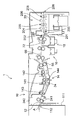
- the automatic developing device 1 shown in FIG. 2 has a development processing unit 10, and a development unit 14, a water washing unit 16, which is continuously formed along the transport direction (arrow A) of the transport path 12 of the planographic printing plate precursor, A desensitizing treatment unit 18 and a drying unit 20 are provided.
- the developing unit 14 is partitioned by an outer panel 111, and the outer panel 111 is provided with a slit-like insertion port 112.
- a developing tank 24 filled with a developing solution and an insertion roller pair 241 for guiding the planographic printing plate precursor into the developing tank 24 are provided inside the developing unit 14.
- the upper part of the developing tank 24 is covered with a shielding lid 242.
- a guide roller 143 and a guide member, a brush roller 141, a submerged transport roller 144, a brush roller 142, and a developing unit outlet roller are arranged in parallel from the upstream side in the transport direction.
- the lithographic printing plate precursor conveyed into the developing tank 24 is immersed in the developer and passes between the rotating brush rollers 141 and 142 to remove non-image portions.
- the lithographic printing plate carried out from the developing tank 24 is supplied with rinsing water by a rinsing spray 66 in the rinsing section 16, and the developer remaining on the plate surface and the like is removed by rinsing, and then the desensitizing processing section 18 performs gumming.
- the liquid (desensitizing liquid) supply spray 72 supplies the desensitizing liquid to the plate surface.
- the partition plate 201 disposed between the development processing unit 10 and the drying unit 20 is provided with a slit-shaped insertion port 202. Further, a shutter (not shown) is provided in the passage between the development processing unit 10 and the drying unit 20, and when the planographic printing plate precursor does not pass through the passage, the passage is closed by the shutter.
- the drying unit 20 includes a support roller 203, a duct 204, a transport roller pair 205, a duct 206, and a transport roller pair 208 in this order. Slit holes are provided at the ends of the ducts 204 and 205.
- the drying unit 20 is provided with drying means (drying member) such as hot air supply means (hot air supply member) and heat generation means (heat generation member) (not shown).
- drying means drying member
- hot air supply means hot air supply member
- heat generation means heat generation member
- the photosensitive lithographic printing plate precursor is subjected to a washing treatment step (ii) after being subjected to a development treatment step (i) [washing step (ii)].
- the water washing step is a step of washing the plate from which the protective layer and the image recording layer corresponding to the unexposed portion have been removed with a developer.
- the water may be water supplied directly from the water supply or water stored in a tank.
- the reclaimed water obtained by the recycling method of the development processing waste liquid of the present invention may be stored in a tank and used in the washing step.
- the washing water is usually sprayed from the washing spray 66 provided in the washing unit 16 onto the lithographic printing plate precursor that has undergone the development process.
- the lithographic printing plate precursor that has undergone the development treatment step and the water washing treatment step is subjected to plate making by applying a desensitizing solution at the desensitizing treatment unit 18 [desensitizing step (iii)], and the lithographic printing plate Is obtained.
- desensitizing treatment step (iii) Photosensitive lithographic printing plates from which the image recording layer in the unexposed area (non-image) has been removed by development processing and washing treatment are disclosed in JP-A Nos. 54-8002, 55-11545, and 59-58431. As described in the above, it is post-treated with a desensitizing solution containing a water-soluble polymer compound such as gum arabic and starch derivatives.
- the desensitizing treatment liquid is supplied to the plate surface by the desensitizing treatment liquid supply spray 72, and the surface of the non-image area is desensitized.
- the non-image area surface is desensitized to maintain the hydrophilicity of the non-image area surface in the lithographic printing plate appropriately, and the occurrence of stains in the non-image area is suppressed, so that the printing durability of the lithographic printing plate is maintained. Will be improved.
- the desensitizing treatment liquid to the surface of the image area, the scratch resistance of the image area is further improved.
- water-soluble polymer compound used in the preparation of the desensitizing solution in the present invention examples include soybean polysaccharide, modified starch, gum arabic, dextrin, fiber derivatives (eg, carboxymethylcellulose, carboxyethylcellulose, methylcellulose, etc.) and modified products thereof.
- Body pullulan, polyvinyl alcohol and its derivatives, polyvinylpyrrolidone, polyacrylamide and acrylamide copolymer, vinyl methyl ether / maleic anhydride copolymer, vinyl acetate / maleic anhydride copolymer, styrene / maleic anhydride copolymer Etc.
- the preferred acid value of the water-soluble polymer compound is 0 meq / g to 3.0 meq / g.
- the plate making waste liquid produced in the plate making step (i) is concentrated by an evaporation concentrator on a volume basis with a concentration (amount of plate making waste after concentration / amount of plate making waste before concentration) in volume. Evaporate and concentrate to 1/2 to 1/10 on the basis.
- the evaporative concentration apparatus includes at least an evaporating kettle that heats the waste liquid without depressurization or heats it under reduced pressure to separate the evaporated water and the remaining concentrate (slurry).
- the evaporative concentration apparatus further includes a cooling kettle that introduces moisture separated as water vapor that may contain an organic solvent into the evaporating kettle and condenses it by cooling to regenerate water.
- the concentration of the waste liquid is preferably performed by a method in which the inside of the evaporation pot is decompressed by a decompression means (a decompression member) and the waste liquid is concentrated by heating. This is because according to this method, the boiling point of the waste liquid is lowered, and the waste liquid can be evaporated and concentrated at a lower temperature than under atmospheric pressure. By using the depressurization means, the waste liquid can be concentrated more safely, and since the concentration is performed at a lower temperature, there is an advantage that the evaporating pot, the waste liquid, and the waste liquid concentrate are not easily affected by heat.
- a decompression means a decompression member
- Examples of pressure reducing means include general water seal type, oil rotary type, diaphragm type mechanical vacuum pumps, diffusion pumps using oil and mercury, multistage turbo compressors, reciprocating compressors, screw compressors, etc. Although a compressor and an aspirator are mentioned, an aspirator is preferable in terms of maintainability and cost.
- Examples of the depressurization condition include depressurization such that the pressure is 666.6 Pa (5 mmHg) to 13332.2 Pa (100 mmHg), preferably 666.6 Pa (5 mmHg) to 3999.7 Pa (30 mmHg).
- As the heating condition a temperature range corresponding to 666.6 Pa to 13332.2 Pa, which is a pressure easily obtained with a water pump or a vacuum pump, is selected.
- the heating temperature can be lowered and the power consumption can be suppressed.
- the heat pump preferably includes a heat radiating portion and a heat absorbing portion.
- the platemaking waste liquid is heated by the heat radiating portion of the heat pump, while the water vapor of the cooling means can be cooled by the heat absorbing portion of the heat pump. That is, the heat concentration of the waste liquid is performed by the heat generated by the heat pump, and the water vapor is condensed by the heat absorption of the heat pump, so that the heat efficiency is good and the heat becomes locally higher than when using heating means such as an electric heater. It has advantages such as being safer, safer, and reducing carbon dioxide emissions.
- the platemaking process waste liquid is heated by a heating means in an evaporation kettle so that the degree of concentration (the amount of the platemaking process waste liquid after concentration / plate making process before concentration) Evaporation is concentrated so that the amount of waste liquid is 1/2 to 1/10 of the volume.
- concentration is 1/2 or more, the amount of waste liquid to be processed is more effectively reduced, and when the concentration is 1/10 or less, the inside of the evaporation pot of the waste liquid concentrating device 30 is reduced.
- Precipitation of solids in the waste liquid concentrated in (1) is less likely to occur, resulting in better maintainability.
- the concentration is preferably in the range of 1/3 to 1/8.
- the reclaimed water obtained as described above is reclaimed water having a low BOD and COD value.
- the BOD value of the reclaimed water is approximately 250 mg / L or less and the COD value of the reclaimed water is 200 mg / L or less. Therefore, the excess reclaimed water may be discharged as it is into the general waste water.
- the reclaimed water contains an organic solvent or the like, a treatment with activated sludge or the like is performed before discharge. Further, as in the recycling method of the present invention to be described later, it is also preferable to recycle the recycled water by supplying it to the developing bath as dilution water or by supplying it as rinsing water in the rinsing section 16.
- a processing solution having a content of an organic solvent in the range of ⁇ 300 ° C. of 2% by mass or less and a pH of 6.0 to 9.5 As described above, the desensitization treatment step (iii) of the non-image area with the desensitizing liquid is performed.
- the development processing waste liquid generated in the development processing step is subjected to a ratio of the development processing waste liquid volume after concentration to the development processing waste liquid volume before concentration (concentration, That is, it occurs in the evaporation concentration step and the evaporation concentration step so that (amount of development processing waste liquid after concentration) / (amount of development processing waste liquid before concentration)) is 1/2 to 1/10 on a volume basis.
- the recycling method of the present invention further includes a reclaimed water supply step in addition to the plate making process, the waste liquid evaporation and concentration step, and the reclaimed water generation step.
- the generated reclaimed water may be supplied to a replenishing water tank or the like and used as diluting water for diluting the developing replenisher at a predetermined magnification in a developing bath disposed in an automatic processor.
- the developer replenisher may be mixed in advance and used to dilute the developer replenisher to a predetermined magnification.
- the reclaimed water may be supplied to the washing unit 14 of the automatic developing apparatus 1 and used as washing water.
- the reclaimed water may be supplied to the desensitizing treatment liquid tank in the desensitizing treatment unit 16.
- the waste liquid processing apparatus described in the gazette etc. is mentioned.
- an exemplary embodiment according to the present invention will be described with reference to the drawings.
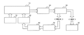
- the recycling method of the development processing waste liquid as shown in FIG. 1, the waste liquid of the developer discharged from the automatic processor 10 during the plate making process of the photosensitive lithographic printing plate is stored in the intermediate tank 20.
- the waste liquid stored and sent from the intermediate tank 20 is heated or heated under reduced pressure by the waste liquid concentrating device 30 and separated into evaporated water and residual concentrate (slurry).
- Reclaimed water obtained by condensing the water separated as water vapor by the waste liquid concentrator 30 by cooling is introduced into the reclaimed water tank 50.
- the waste liquid concentrated by the waste liquid concentrating device 30 is collected in the waste liquid collection tank 40. Transfer of the concentrated waste liquid to the waste liquid tank 40 is preferably performed by pressurizing with a pump.
- the waste liquid concentrator 30 is an evaporation pot (not shown) for separating the waste liquid sent from the intermediate tank 20 into heated water or under reduced pressure without reducing pressure, and separating it into evaporated water and residual concentrate (slurry). And a cooling kettle (not shown) that introduces moisture separated as water vapor (which may contain an organic solvent) in the evaporating kettle and condenses by cooling to form reclaimed water.
- a recycled water tank 50 that temporarily stores the recycled water and a distilled recycled water recycling apparatus 60 that controls the supply of the recycled water to the automatic developing machine 10 are used.
- the distilled reclaimed water reuse device 60 is preferably connected by piping to a replenishment water tank 80 for supplying reclaimed water to the automatic processor 10.
- a pipe connecting the replenishing water tank 80 and the developing bath of the automatic processor 10 is provided with a pressure gauge for measuring the pressure in the pipe and a pump.
- the distilled reclaimed water recycling apparatus 60 has an analyzer for analyzing the components of the reclaimed water, and means (members) for preparing a composition by performing neutralization, supplying fresh water, etc.
- the driving of the pump is controlled according to the pressure value measured by the pressure gauge, and the reclaimed water collected by driving the pump is supplied from the replenishing water tank 80 to the automatic developing device 10. Further, the developing replenisher is supplied from the developer replenisher tank 70 to the automatic developing machine 10.
- the reclaimed water obtained by this system may contain an organic solvent as long as it is 0.5% or less based on the volume.
- the reclaimed water obtained by this system is reclaimed water having a low BOD and COD value.
- the BOD value of reclaimed water obtained by the system is approximately 250 mg / L or less
- the COD value of reclaimed water is approximately 200 mg / L or less. Therefore, the reclaimed water is evaporated in an automatic processor. It can be used as a dilution water for correction, a dilution water for a developing replenisher, a rinsing water for washing a plate, or a washing water for an automatic developing machine. In addition, excess reclaimed water may be discharged as it is into general waste water.
- the developer replenisher is diluted and supplied to the developing bath of the automatic processor 10.
- the amount of reclaimed water supplied from the replenishing water tank 80 is controlled in accordance with the amount of developing replenisher supplied from the developer replenisher tank 70, and the system shown in FIG.
- the developing replenisher may be diluted at a predetermined magnification in a developing bath that is not used.
- the present invention is not limited to this embodiment, and the developer replenisher and regenerated water are mixed in advance to dilute the developer replenisher to a predetermined magnification, and then the diluted developer replenisher is supplied into the developing bath. May be.
- the platemaking process waste liquid generated from a plurality of automatic processors may be collected in one waste liquid concentrator, and the obtained reclaimed water may be supplied as dilution water or rinse water to the plurality of automatic processors.
- the reclaimed water as the replenishing water in this way, the processing amount of the lithographic printing plate precursor that is appropriately subjected to the plate making process is increased without supplying dilution water or the like to the automatic processor.
- a photosensitive lithographic printing plate precursor according to the present invention comprises a radically polymerizable image recording layer containing (a) an infrared absorbing dye, (b) a polymerization initiator, and (c) a polymerizable compound on a support; And a protective layer in this order.
- a radically polymerizable image recording layer containing (a) an infrared absorbing dye, (b) a polymerization initiator, and (c) a polymerizable compound on a support; And a protective layer in this order.
- the infrared absorbing dye has a function of converting the absorbed infrared light into heat and a function of being excited by the infrared light and transferring electrons and / or energy to a radical polymerization initiator described later.
- the infrared absorbing dye used in the present invention is a dye having an absorption maximum at a wavelength of 760 to 1200 nm.
- dyes such as azo dyes, metal complex azo dyes, pyrazolone azo dyes, naphthoquinone dyes, anthraquinone dyes, phthalocyanine dyes, carbonium dyes, quinoneimine dyes, methine dyes, cyanine dyes, squarylium dyes, pyrylium salts, metal thiolate complexes Is mentioned.
- cyanine dyes particularly preferred among these dyes are cyanine dyes, squarylium dyes, pyrylium salts, nickel thiolate complexes, and indolenine cyanine dyes. Further, cyanine dyes and indolenine cyanine dyes are preferred, and particularly preferred examples include cyanine dyes represented by the following general formula (e).
- X 1 represents a hydrogen atom, a halogen atom, —N (R 9 ) (R 10 ), —X 2 -L 1 or a group shown below.
- R 9 and R 10 may be the same or different, and may have a substituent, an aryl group having 6 to 10 carbon atoms, an alkyl group having 1 to 8 carbon atoms, or a hydrogen atom.
- R 9 and R 10 may be bonded to each other to form a ring. Of these, a phenyl group is preferred (—NPh 2 ).
- X 2 represents an oxygen atom or a sulfur atom
- L 1 represents a hydrocarbon group having 1 to 12 carbon atoms, a heteroaryl group, or a hydrocarbon group having 1 to 12 carbon atoms including a hetero atom.
- a hetero atom shows N, S, O, a halogen atom, or Se here.
- Xa - has Za described later - is defined as for, Ra represents a hydrogen atom, an alkyl group, an aryl group, a substituted or unsubstituted amino group, and substitutions selected from the group consisting of halogen atoms Represents a group.
- R 1 and R 2 each independently represents a hydrocarbon group having 1 to 12 carbon atoms.
- R 1 and R 2 are preferably each independently a hydrocarbon group having 2 or more carbon atoms.
- R 1 and R 2 may be connected to each other to form a ring, and when a ring is formed, it is particularly preferable to form a 5-membered ring or a 6-membered ring.
- Ar 1 and Ar 2 may be the same or different and each represents an aryl group which may have a substituent.
- Preferred aryl groups include a benzene ring and a naphthalene ring.
- a C12 or less hydrocarbon group, a halogen atom, and a C12 or less alkoxy group are mentioned.
- Y 1 and Y 2 may be the same or different and each represents a sulfur atom or a dialkylmethylene group having 12 or less carbon atoms.
- R 3 and R 4 may be the same or different and each represents a hydrocarbon group having 20 or less carbon atoms which may have a substituent.
- Preferred substituents include alkoxy groups having 12 or less carbon atoms, carboxy groups, and sulfo groups.
- R 5 , R 6 , R 7 and R 8 may be the same or different and each represents a hydrogen atom or a hydrocarbon group having 12 or less carbon atoms. From the availability of raw materials, a hydrogen atom is preferred.
- Za ⁇ represents a counter anion. However, Za ⁇ is not necessary when the cyanine dye represented by the general formula (e) has an anionic substituent in its structure and neutralization of charge is not necessary.
- Preferred Za ⁇ is a halide ion, a perchlorate ion, a tetrafluoroborate ion, a hexafluorophosphate ion, and a sulfonate ion, particularly preferably a perchlorate ion, in view of the storage stability of the image recording layer coating solution.
- Hexafluorophosphate ions, and aryl sulfonate ions are examples of the storage stability of the image recording layer coating solution.
- More preferable infrared absorbing dyes in the present invention include cyanine dyes represented by the following general formula (e-2).
- Z 1 and Z 2 each independently represent an aromatic ring or a heteroaromatic ring which may have a substituent.
- Preferred aromatic rings include a benzene ring and a naphthalene ring.
- Preferred substituents include a hydrocarbon group having 12 or less carbon atoms, a halogen atom, an alkoxy group having 12 or less carbon atoms, a hydrocarbon group having 12 or less carbon atoms, and 12 carbon atoms. Most preferred are not more than alkoxy groups.
- R 3 and R 4 each independently represent a hydrocarbon group having 20 or less carbon atoms which may have a substituent.
- Preferred substituents include alkoxy groups having 12 or less carbon atoms, carboxy groups, and sulfo groups.
- R 9 and R 10 each independently represent a hydrogen atom or an alkoxy group which may have a substituent.
- Za ⁇ represents a counter anion present when charge neutralization is required.
- Preferred Za ⁇ is a halide ion, a perchlorate ion, a tetrafluoroborate ion, a hexafluorophosphate ion, and a sulfonate ion, particularly preferably a perchlorate ion, in view of the storage stability of the image recording layer coating solution. , Hexafluorophosphate ions, and aryl sulfonate ions.
- cyanine dye represented by formula (e) that can be suitably used include compounds described in paragraphs [0017] to [0019] of JP-A No. 2001-133969, JP-A No. 2002-023360.
- Examples include the compounds described in paragraph numbers [0016] to [0021] of JP-A No. 2002-040638, paragraph numbers [0012] to [0037] of JP-A No. 2002-040638, and preferably paragraph Nos. Of JP-A No. 2002-278057.
- infrared absorbing dyes may be used alone or in combination of two or more, or an infrared absorbing pigment other than the infrared absorbing dye may be used in combination.
- pigment compounds described in paragraph numbers [0072] to [0076] of JP-A-2008-195018 are preferable.
- the content of the infrared absorbing dye in the image recording layer is preferably 0.1 to 10.0% by mass, more preferably 0.5 to 5.0% by mass, based on the total solid content of the image recording layer.
- the (b) radical generator is a compound that initiates and / or accelerates the polymerization of the (c) polymerizable compound.
- a known thermal polymerization initiator a compound having a bond with a small bond dissociation energy, a photopolymerization initiator, or the like can be used.
- radical generators are (1) organic halides, (2) carbonyl compounds, (3) azo compounds, (4) organic peroxides, (5) metallocene compounds, (6) azide compounds, (7) Examples include hexaarylbiimidazole compounds, (8) organic borate compounds, (9) disulfone compounds, (10) oxime ester compounds, and (11) onium salt compounds.
- the metallocene compound for example, the compound described in paragraph [0026] of JP-A-2008-195018 is preferable.
- the azide compound include compounds such as 2,6-bis (4-azidobenzylidene) -4-methylcyclohexanone.
- hexaarylbiimidazole compound for example, a compound described in paragraph [0027] of JP-A-2008-195018 is preferable.
- organic borate compound for example, compounds described in paragraph No. [0028] of JP-A-2008-195018 are preferable.
- Examples of the disulfone compound include compounds described in JP-A Nos. 61-166544 and 2002-328465.
- onium salt compounds examples include S.I. I. Schlesinger, Photogr. Sci. Eng. , 18, 387 (1974), T.A. S. Diazonium salts described in Bal et al, Polymer, 21, 423 (1980), ammonium salts described in US Pat. No. 4,069,055, JP-A-4-365049, etc., US Pat. No. 4,069 , 055, 4,069,056, phosphonium salts described in European Patent Nos. 104 and 143, U.S. Patent Application Publication No. 2008/0311520, JP-A-2-150848, Iodonium salts described in JP-A-2008-195018, European Patent Nos.
- German Patent 2,904 626 No. the 3,604,580 Patent, sulfonium salts described in the specification of Nos. 3,604,581, J. V. Crivello et al, Macromolecules, 10 (6), 1307 (1977), J. MoI. V. Crivello et al, J.A. Polymer Sci. , Polymer Chem. Ed. , 17, 1047 (1979), a selenonium salt described in C.I. S. Wen et al, Teh, Proc. Conf. Rad. Curing ASIA, p478 Tokyo, Oct (1988), and onium salts such as azinium salts described in JP-A-2008-195018.
- onium salts especially iodonium salts, sulfonium salts and azinium salts, and (7) hexaarylbiimidazole compounds. Specific examples of these compounds are shown below, but the scope of the present invention is not limited thereto.
- Examples of preferred iodonium salts include diphenyl iodonium salts, more preferred are diphenyl iodonium salts substituted with an electron donating group such as an alkyl group or an alkoxyl group, and even more preferred are asymmetric diphenyl iodonium salts. It is done.
- diphenyliodonium hexafluorophosphate
- 4-methoxyphenyl-4- (2-methylpropyl) phenyliodonium hexafluorophosphate
- 4- (2-methylpropyl) phenyl-p-tolyliodonium hexa Fluorophosphate
- 4-hexyloxyphenyl-2,4,6-trimethoxyphenyliodonium hexafluorophosphate
- 4-hexyloxyphenyl-2,4-diethoxyphenyliodonium tetrafluoroborate
- 4-octyloxy Phenyl-2,4,6-trimethoxyphenyliodonium 1-perfluorobutanesulfonate
- 4-octyloxyphenyl-2,4,6-trimethoxyphenyliodonium hexafluorophosphate, bis ( -t- butylphenyl) iodonium
- the hexaarylbiimidazole compounds include 2,2′-bis (o-chlorophenyl) -4,4 ′, 5,5′-tetraphenylbiimidazole, 2,2′-bis (o-bromophenyl)) 4, 4 ′, 5,5′-tetraphenylbiimidazole, 2,2′-bis (o, p-dichlorophenyl) -4,4 ′, 5,5′-tetraphenylbiimidazole, 2,2′-bis (o -Chlorophenyl) -4,4 ′, 5,5′-tetrakis (m-methoxyphenyl) biidazole, 2,2′-bis (o, o′-dichlorophenyl) -4,4 ′, 5,5′-tetraphenyl Biimidazole, 2,2′-bis (o-nitrophenyl) -4,4 ′, 5,5′-tetraphen
- the content of the radical generator is preferably 0.1% by mass to 50% by mass, more preferably 0.5% by mass to 30% by mass, and particularly preferably 0.8% by mass with respect to the total solid content of the image recording layer. ⁇ 20% by weight. Within this range, good sensitivity and good stain resistance of the non-image area during printing can be obtained.
- the polymerizable compound used in the image recording layer is an addition polymerizable compound having at least one ethylenically unsaturated double bond, and is selected from compounds having at least one terminal ethylenically unsaturated bond, preferably two or more. . These can take chemical forms such as monomers, prepolymers, ie dimers, trimers and oligomers, or mixtures thereof.
- Examples of monomers include unsaturated carboxylic acids (for example, acrylic acid, methacrylic acid, itaconic acid, crotonic acid, isocrotonic acid, maleic acid, etc.), esters and amides thereof, preferably unsaturated carboxylic acids.
- An ester of an acid and a polyhydric alcohol compound and an amide of an unsaturated carboxylic acid and a polyvalent amine compound are used.
- an addition reaction product of an unsaturated carboxylic acid ester or amide having a nucleophilic substituent such as a hydroxy group, an amino group or a mercapto group with a monofunctional or polyfunctional isocyanate or epoxy, and a monofunctional or polyfunctional compound.
- a dehydration condensation reaction product with a functional carboxylic acid is also preferably used.
- a substitution reaction product of an unsaturated carboxylic acid ester or amide having a leaving substituent such as a tosyloxy group and a monofunctional or polyfunctional alcohol, amine or thiol is also suitable.
- tris (acryloyloxyethyl) isocyanurate and bis (acryloyloxyethyl) hydroxyethyl are preferred because of the excellent balance between the hydrophilicity involved in on-press developability and the polymerization ability involved in printing durability.
- Isocyanuric acid ethylene oxide modified acrylates such as isocyanurates are particularly preferred.
- the details of the method of use such as the structure of these polymerizable compounds, whether only one is used or two or more are used together, and the amount added can be arbitrarily set in accordance with the performance design of the final lithographic printing plate precursor.
- the polymerizable compound is preferably 5% by mass to 75% by mass, more preferably 10% by mass to 70% by mass, and particularly preferably 15% by mass to 60% by mass with respect to the total solid content of the image recording layer. Used in range.
- a binder polymer may be used in order to improve the film strength of the image recording layer.
- the binder polymer any conventionally known polymer can be used without limitation, and a polymer having a film property is preferable. Of these, acrylic resins, polyvinyl acetal resins, and polyurethane resins are preferable.
- the main chain or the side chain preferably the side chain, has a crosslinkable functional group for improving the film strength of the image area. Things. Crosslinking is formed between the polymer molecules by the crosslinkable group, and curing is accelerated.
- the crosslinkable functional group is preferably an ethylenically unsaturated group such as a (meth) acryl group, vinyl group, allyl group, or styryl group, or an epoxy group, and these groups are introduced into the polymer by polymer reaction or copolymerization.
- a reaction between an acrylic polymer or polyurethane having a carboxy group in the side chain and polyurethane and glycidyl methacrylate, or a reaction between a polymer having an epoxy group and an ethylenically unsaturated group-containing carboxylic acid such as methacrylic acid can be used.
- the content of the crosslinkable group in the binder polymer is preferably 0.1 mmol to 10.0 mmol, more preferably 0.25 mmol to 7.0 mmol, and most preferably 0.5 mmol to 5.5 mmol per 1 g of the binder polymer. .
- the binder polymer preferably further has a hydrophilic group.
- the hydrophilic group contributes to imparting on-press developability to the image recording layer.
- the coexistence of the crosslinkable group and the hydrophilic group makes it possible to achieve both printing durability and developability.
- hydrophilic group examples include a hydroxy group, a carboxy group, an alkylene oxide structure, an amino group, an ammonium group, an amide group, a sulfo group, and a phosphoric acid group.
- an alkylene oxide unit having 2 or 3 carbon atoms An alkylene oxide structure having 1 to 9 is preferred.
- a monomer having a hydrophilic group may be copolymerized.
- an oleophilic group such as an alkyl group, an aryl group, an aralkyl group or an alkenyl group can be introduced in order to control the inking property.
- a lipophilic group-containing monomer such as an alkyl methacrylate may be copolymerized.
- the binder polymer Specific examples (1) to (11) of the binder polymer are shown below, but the present invention is not limited thereto.
- the number given to each repeating unit represents the molar ratio of the content of the repeating unit contained in the binder polymer.
- the binder polymer preferably has a mass average molar mass (Mw) of 2000 or more, more preferably 5000 or more, and still more preferably 10,000 to 300,000.
- the polymer compound used in the present invention is a star polymer having a main chain branched into three or more, and is a polymer compound represented by the following general formula (P-1).
- A represents a branch unit (constituent unit including a branch point) of a star polymer
- Polymer represents a polymer chain as a main chain, a polyethyleneoxy group and a polypropyleneoxy group as side chains. And a partial structure having at least one selected from a group. n is 3 or more.
- the star polymer is a polymer compound having a polymer chain having the main chain structure as described above and having at least one selected from a polyethyleneoxy group and a polypropyleneoxy group as a side chain.
- the side chain may contain only one of polyethyleneoxy group or polypropyleneoxy group, or may contain both groups.
- the polyethyleneoxy group or polypropyleneoxy group is a group represented by the following general formula (P-2).
- R 1 represents a hydrogen atom or a methyl group
- R 2 represents a hydrogen atom or an alkyl group having 1 to 12 carbon atoms
- n is preferably 2 to 90, more preferably 2 to 50, still more preferably. It represents 2 to 12, particularly preferably 2 to 8.
- R 1 is a hydrogen atom and R 2 is a hydrogen atom or a methyl group.
- n is more preferably from 2 to 12, and particularly preferably from 2 to 8.
- a monomer of the following general formula (P-3) may be copolymerized.
- R 3 represents a methyl group or a hydrogen atom
- L represents an oxygen atom or NH.
- L is preferably an oxygen atom.
- R 1, R 2 and n are general formula (P-2) have the same meanings as R 1, R 2 and n of a same preferred.
- the ratio of the repeating unit from the monomer represented by the general formula (3) is preferably 20% by mass to 80% by mass, more preferably 30% by mass to 70% in the polymer compound represented by the general formula (1). % By mass, particularly preferably 35% by mass to 65% by mass.
- the polymer of the general formula (P-1) includes a repeating unit having an ethylenically unsaturated group. Ethylenically unsaturated groups form crosslinks between polymer molecules during photopolymerization and promote photocuring.
- a (meth) acryl group As the ethylenically unsaturated group, a (meth) acryl group, a vinyl group, an allyl group and the like are preferable, and these groups can be introduced into a polymer by a polymer reaction or copolymerization.
- reaction between an acrylic polymer having a carboxy group in the side chain and glycidyl methacrylate reaction between a polymer having an epoxy group and an ethylenically unsaturated group-containing carboxylic acid such as methacrylic acid, or a polymer having a hydroxy group and an isocyanate group Reaction with methacrylate can be used.
- a (meth) acryl group is preferred.
- repeating unit having an ethylenically unsaturated group used in the present invention are described below.
- the present invention is not limited to these.
- the content of the ethylenically unsaturated group in the polymer compound of the present invention is preferably 0.1 mmol to 10.0 mmol, more preferably 0.25 mmol to 7.0 mmol, most preferably 0, per 1 g of the polymer compound. 0.5 mmol to 5.5 mmol.
- the star polymer may contain other repeating units. Specific examples of such repeating units are described below. The present invention is not limited to these.
- (M1) Acrylic acid esters and methacrylic acid esters having an aliphatic hydroxy group such as 2-hydroxyethyl acrylate or 2-hydroxyethyl methacrylate.
- (M2) Alkyl acrylates such as methyl acrylate, ethyl acrylate, propyl acrylate, butyl acrylate, amyl acrylate, hexyl acrylate, octyl acrylate, benzyl acrylate, 2-chloroethyl acrylate, and glycidyl acrylate.
- Alkyl methacrylates such as methyl methacrylate, ethyl methacrylate, propyl methacrylate, butyl methacrylate, amyl methacrylate, hexyl methacrylate, cyclohexyl methacrylate, benzyl methacrylate, 2-chloroethyl methacrylate and glycidyl methacrylate.
- (M4) Acrylamide, methacrylamide, N-methylolacrylamide, N-ethylacrylamide, N-hexylmethacrylamide, N-cyclohexylacrylamide, N-hydroxyethylacrylamide, N-phenylacrylamide, N-nitrophenylacrylamide, N-ethyl- Acrylamide or methacrylamide such as N-phenylacrylamide.
- (M5) Vinyl ethers such as ethyl vinyl ether, 2-chloroethyl vinyl ether, hydroxyethyl vinyl ether, propyl vinyl ether, butyl vinyl ether, octyl vinyl ether, and phenyl vinyl ether.
- (M6) Vinyl esters such as vinyl acetate, vinyl chloroacetate, vinyl butyrate and vinyl benzoate.
- Styrenes such as styrene, ⁇ -methylstyrene, methylstyrene, chloromethylstyrene.
- (M8) Vinyl ketones such as methyl vinyl ketone, ethyl vinyl ketone, propyl vinyl ketone, and phenyl vinyl ketone.
- Olefins such as ethylene, propylene, isobutylene, butadiene and isoprene.
- M10 N-vinylpyrrolidone, acrylonitrile, methacrylonitrile and the like.
- Unsaturated imides such as maleimide, N-acetylmethacrylamide, N-propionylmethacrylamide, N- (p-chlorobenzoyl) methacrylamide.
- the branch unit represented by A in the general formula (P-1) is not particularly limited, but preferably has a hub portion which is a residue of a thiol having 3 or more functionalities.
- the addition polymer backbone extends from each thio moiety in the hub; thus, three or more backbones extend from the thio moiety. That is, the branch unit A preferably has a structure represented by the following general formula (P-4).
- a 1 is a trivalent or higher organic group, and n is an integer of 3 or higher.
- Specific examples of A 1 include the following structures or organic groups constituted by combining a plurality of these structures.
- n is preferably an integer of 3 to 6, particularly preferably an integer of 4 to 6.
- Trifunctional or higher thiol residues are derived from aromatic or aliphatic thiols.
- aromatic thiols include benzene-1,3,5-trithiol, 3,4,8,9-tetramercaptotetrathiafulvalene and 7-methyltrithiouric acid.
- the thiol residue of the aliphatic thiol is preferably an ester residue formed from a trifunctional or higher alcohol and a mercaptoalkanoic acid having 2 to 6 carbon atoms.
- suitable alcohols include glycerin, sorbitol, alcohol represented by formula (P-5), and alcohol having a group represented by formula (P-6).
- an alcohol represented by the formula (P-5) and an alcohol having a group represented by the formula (P-6) are preferable.
- R 1 represents a hydrogen atom, an alkyl group having 1 to 4 carbon atoms, or a hydroxy-substituted alkyl group.
- a methyl group, an ethyl group, a hydroxymethyl group, and a hydroxyethyl group are preferable.
- Examples of mercaptoalkanoic acids having 2 to 6 carbon atoms include 2-mercaptoacetic acid, 2-mercaptopropionic acid, 3-mercaptopropionic acid, 4-mercaptobutyric acid, 5-mercaptovaleric acid, and 6-mercaptocaproic acid. It is done. Of these, 2-mercaptoacetic acid and 3-mercaptopropionic acid are preferable.
- esters formed from tri- or higher functional alcohols and mercaptoalkanoic acids having 2 to 6 carbon atoms include 1,2,6-hexanetriol trithioglycolate, 1,3,5-trithiocyanuric acid, 1,3,5-tris (3-mercaptobutyryloxyethyl) -1,3,5-triazine-2,4,6 (1H, 3H, 5H) -trione, trimethylolpropane tris (3-mercaptopropio Nate), trimethylolpropane tristhioglycolate, trimethylolpropane tristhiopropionate, trihydroxyethyltriisocyanuric acid tristhiopropionate, tris-[(ethyl-3-mercaptopropionyloxy) -ethyl] isocyanurate Compounds having three mercapto groups such as pentaerythritol Compounds having four mercapto groups such as tetrakis (3-
- TMTG trimethylolpropane tristhiopropionate
- PETG pentaerythritol tetrakisthiopropionate
- Karenz MT PE1 penta Erythritol tetrakis (3-mercaptobutyrate)
- Karenz MT PE1 trademark
- Karenz MT NR1 trimethylolpropane tris-3-mercaptopropionate
- PEMP pentaerythritol tetrakis-3- Mercaptopropionate
- Examples of the branch unit represented by formula (P-1) include those having the following structure.
- the weight average molecular weight (Mw) of the star polymer is preferably 5,000 to 500,000, and more preferably 10,000 to 250,000. Specific examples of the star polymer are shown in Table 1 below together with the weight average molecular weight depending on the branch unit and the type of polymer chain bonded to the tip. However, the star polymer that can be used in the present invention is not limited thereto.
- One type of star polymer may be included in the image recording layer, or two or more types may be included in the image recording layer.
- the content of the star polymer in the image recording layer is preferably in the range of 0.5% by mass to 90% by mass with respect to the total solid content of the image recording layer, and in the range of 1% by mass to 80% by mass. More preferably, it is more preferably in the range of 1.5 mass% to 70 mass%.
- the star polymer can be synthesized by a known method such as radical polymerization of the monomer constituting the polymer chain in the presence of the polyfunctional thiol compound.
- the image recording layer may contain fine polymer particles in order to improve developability.
- polymer fine particles having a polyalkylene oxide structure are preferred. Of these, polymer fine particles having a polyalkylene oxide group in the side chain are preferred.
- the polyalkylene oxide structure is preferably an alkylene oxide structure having 2 to 120 alkylene oxide units having 2 or 3 carbon atoms, and more preferably a polyethylene oxide structure having 2 to 120 ethylene oxide units. In particular, a polyethylene oxide structure having 20 to 100 ethylene oxide units is preferred.
- the fine polymer particles having such a polyalkylene oxide structure can achieve both printing durability and developability. Moreover, the inking property can be improved.
- the polymer fine particles are preferably a hydrophobized precursor that can convert the image recording layer to be hydrophobic when heat is applied.
- the hydrophobized precursor polymer fine particles include a group consisting of hydrophobic thermoplastic polymer fine particles, heat-reactive polymer fine particles, microcapsules enclosing at least a part of components of the image recording layer, and microgel (crosslinked polymer fine particles). At least one particle selected from the above is preferred. Among these, polymer fine particles and microgels having a polymerizable group are preferable. In order to improve developability, it is preferable to have a polyalkylene oxide structure as described above.
- Hydrophobic thermoplastic polymer fine particles include Research Disclosure No. 1 of January 1992. 331,003, JP-A-9-123387, JP-A-9-131850, JP-A-9-171249, JP-A-9-171250, and European Patent No. 931647 are suitable.
- polymer constituting the polymer fine particle examples include ethylene, styrene, vinyl chloride, methyl acrylate, ethyl acrylate, methyl methacrylate, ethyl methacrylate, vinylidene chloride, acrylonitrile, vinyl carbazole, acrylate having a polyalkylene structure, or Mention may be made of homopolymers or copolymers of monomers such as methacrylates or mixtures thereof. Among them, more preferable examples include a copolymer containing polystyrene, styrene and acrylonitrile, and polymethyl methacrylate.
- the average particle diameter of the hydrophobic thermoplastic polymer fine particles is preferably 0.01 ⁇ m to 2.0 ⁇ m.
- heat-reactive polymer fine particles examples include polymer fine particles having a heat-reactive group, and these form a hydrophobic region by cross-linking due to a heat reaction and a functional group change at that time.
- the heat-reactive group in the polymer fine particle having a heat-reactive group may be any functional group that performs a reaction as long as a chemical bond is formed, but an ethylenically unsaturated group that performs a radical polymerization reaction (for example, An acryloyl group, a methacryloyl group, a vinyl group, an allyl group, etc.), a cationic polymerizable group (for example, a vinyl group, a vinyloxy group, etc.), an isocyanate group that performs an addition reaction or a block thereof, an epoxy group, a vinyloxy group, and these reactions.
- a radical polymerization reaction for example, An acryloyl group, a methacryloyl group, a vinyl group, an allyl group, etc.
- a cationic polymerizable group for example, a vinyl group, a vinyloxy group, etc.
- an isocyanate group that performs an addition reaction or a block thereof, an epoxy group
- Functional group for example, amino group, hydroxy group, carboxy group, etc. having an active hydrogen atom as a partner, a carboxy group that performs a condensation reaction, a hydroxy group or amino group that is a reaction partner, an acid anhydride that performs a ring-opening addition reaction
- an amino group or a hydroxy group which is a reaction partner can be preferably mentioned.
- the microcapsule for example, as described in JP-A-2001-277740, JP-A-2001-277742, and EP2383118, all or part of the constituent components of the image recording layer are encapsulated in the microcapsule. Is mentioned.
- the constituent components of the image recording layer can also be contained outside the microcapsules.
- the image recording layer containing the microcapsule includes a hydrophobic constituent component in the microcapsule and a hydrophilic constituent component outside the microcapsule.
- the image recording layer may contain crosslinked resin particles, that is, microgel.
- the microgel can contain a part of the components of the image recording layer in and / or on the surface thereof.
- the aspect which made the reactive microgel by having a polymeric compound on the surface is especially preferable from a viewpoint of image formation sensitivity or printing durability.
- the average particle size of the microcapsules or microgel is preferably 0.01 ⁇ m to 3.0 ⁇ m. 0.05 ⁇ m to 2.0 ⁇ m is more preferable, and 0.10 ⁇ m to 1.0 ⁇ m is particularly preferable. Within this range, good resolution and stability over time can be obtained.
- the content of the polymer fine particles is preferably in the range of 5 mass% to 90 mass% of the total solid content of the image recording layer.
- the image recording layer can further contain the following components as required.
- the image recording layer may contain a low molecular weight hydrophilic compound in order to improve the on-press developability without reducing the printing durability.
- a low molecular weight hydrophilic compound for example, as the water-soluble organic compound, ethylene glycol, diethylene glycol, triethylene glycol, propylene glycol, dipropylene glycol, tripropylene glycol and the like glycols and ether or ester derivatives thereof, glycerin, Polyols such as pentaerythritol and tris (2-hydroxyethyl) isocyanurate, organic amines such as triethanolamine, diethanolamine and monoethanolamine and salts thereof, organic sulfones such as alkylsulfonic acid, toluenesulfonic acid and benzenesulfonic acid Acids and salts thereof, organic sulfamic acids such as alkylsulfamic acid and salts thereof, organic sulfuric acids such as alkyl
- the image recording layer preferably contains at least one selected from the group consisting of polyols, organic sulfates, organic sulfonates, and betaines.
- organic sulfonates include alkyl sulfonates such as sodium n-butyl sulfonate, sodium n-hexyl sulfonate, sodium 2-ethylhexyl sulfonate, sodium cyclohexyl sulfonate, and sodium n-octyl sulfonate.
- Organic sulfates include polyethylene oxide alkyl ether sulfates, polyethylene oxide alkenyl ether sulfates, polyethylene oxide alkynyl ether sulfates, polyethylene oxide aryl ether sulfates, or polyethylene oxide heterocyclic monoethers.
- the number of ethylene oxide units contained in the polyethylene oxide is preferably 1 to 4, and the sulfate is preferably a sodium salt, potassium salt or lithium salt. Specific examples thereof include compounds described in paragraph numbers [0034] to [0038] of JP-A-2007-276454.
- betaines compounds in which the hydrocarbon substituent on the nitrogen atom has 1 to 5 carbon atoms are preferable.
- Specific examples include trimethylammonium acetate, dimethylpropylammonium acetate, 3-hydroxy-4-trimethyl.
- the above low molecular weight hydrophilic compound has a small hydrophobic part structure and almost no surface-active action, so that dampening water penetrates into the exposed part of the image recording layer (image part) and the hydrophobicity and film strength of the image part. Ink acceptability and printing durability of the image recording layer can be maintained satisfactorily.
- the content of these low molecular weight hydrophilic compounds in the image recording layer is preferably 0.5% by mass or more and 20% by mass or less of the total solid content of the image recording layer. More preferably, they are 1 mass% or more and 15 mass% or less, More preferably, they are 2 mass% or more and 10 mass% or less. In this range, good on-press developability and printing durability can be obtained. Only one of these compounds may be included, or two or more combinations may be included.
- the image-recording layer may contain a fat-sensitizing agent such as a phosphonium compound, a nitrogen-containing low molecular weight compound, or an ammonium group-containing polymer in the image-recording layer in order to improve the inking property.
- a fat-sensitizing agent such as a phosphonium compound, a nitrogen-containing low molecular weight compound, or an ammonium group-containing polymer in the image-recording layer in order to improve the inking property.
- the sensitizer functions as a surface coating agent and prevents a decrease in the inking property during printing by the inorganic stratiform compound.
- the content of the sensitizer is preferably 0.01% by mass to 30.0% by mass, more preferably 0.1% by mass to 15.0% by mass with respect to the total solid content of the image recording layer, and 1% by mass. % To 10% by mass is more preferable.
- the image recording layer further comprises other components such as a surfactant, a colorant, a printout agent, a polymerization inhibitor, an ultraviolet absorber, a higher fatty acid derivative, a plasticizer, inorganic fine particles, an inorganic layered compound, and an increase.
- You may contain a sensitization agent or a chain transfer agent.
- the image recording layer is prepared by dispersing or dissolving the necessary components described above in a known solvent. It is formed by coating this on a support by a known method such as bar coater coating and drying.
- the image recording layer coating amount (solid content) on the support obtained after coating and drying varies depending on the use, but is generally preferably 0.3 g / m 2 to 3.0 g / m 2 . Within this range, good sensitivity and good film characteristics of the image recording layer can be obtained.
- the lithographic printing plate precursor preferably has an undercoat layer (sometimes referred to as an intermediate layer) between the image recording layer and the support.
- the undercoat layer enhances the adhesion between the support and the image recording layer in the exposed area, and easily peels off the image recording layer from the support in the unexposed area. Contributes to improvement.
- the undercoat layer functions as a heat insulating layer, thereby preventing the heat generated by the exposure from diffusing to the support and lowering the sensitivity.
- Examples of the compound used for the undercoat layer include compounds having an acid group such as phosphonic acid, phosphoric acid, and sulfonic acid. Further, those having an adsorptive group that can be adsorbed on the surface of the support and those having a crosslinkable group in order to improve adhesion to the image recording layer are preferred. These compounds may be low molecular weight or high molecular weight polymers. Two or more of these compounds may be used as necessary.
- the polymer is preferably a copolymer of a monomer having an adsorptive group, a monomer having a hydrophilic group, and a monomer having a crosslinkable group.
- the adsorptive group that can be adsorbed on the support surface include a phenolic hydroxy group, a carboxy group, —PO 3 H 2 , —OPO 3 H 2 , —CONHSO 2 —, —SO 2 NHSO 2 —, —COCH 2 COCH 3 Is preferred.
- a sulfo group is preferable.
- the crosslinkable group is preferably a methacryl group or an allyl group.
- This polymer may have a crosslinkable group introduced by salt formation between the polar substituent of the polymer, a substituent having a counter charge and a compound having an ethylenically unsaturated bond,
- Other monomers preferably hydrophilic monomers, may be further copolymerized.
- the phosphorus compound which has a heavy bond reactive group is mentioned suitably.
- Crosslinkable group (preferably ethylenically unsaturated bond group), support described in JP-A-2005-238816, JP-A-2005-125649, JP-A-2006-239867, JP-A-2006-215263 Those containing a low molecular compound or a high molecular compound having a functional group interacting with the surface and / or a hydrophilic group are also preferable. More preferred are polymer polymers having adsorbable groups, hydrophilic groups, and crosslinkable groups that can be adsorbed on the support surface described in JP-A Nos. 2005-125749 and 2006-188038.
- the content of unsaturated double bonds in the polymer for the undercoat layer is preferably 0.1 mmol to 10.0 mmol, more preferably 0.2 mmol to 5.5 mmol per 1 g of the polymer.
- the polymer for the undercoat layer preferably has a mass average molar mass of 5000 or more, more preferably 10,000 to 300,000.
- the undercoat layer according to the present invention includes a chelating agent, a secondary or tertiary amine, a polymerization inhibitor, an amino group, or a functional group having a polymerization inhibitory ability, in addition to the above-mentioned undercoat layer compound, to prevent contamination over time.
- a compound having a group that interacts with the surface of an aluminum support for example, 1,4-diazabicyclo [2,2,2] octane (DABCO), 2,3,5,6-tetrahydroxy-p-quinone, Chloranil, sulfophthalic acid, hydroxyethylethylenediaminetriacetic acid, dihydroxyethylethylenediaminediacetic acid, hydroxyethyliminodiacetic acid, etc.
- the undercoat layer is applied by a known method.
- the coating amount (solid content) of the undercoat layer is preferably 0.1 mg / m 2 to 100 mg / m 2 , and more preferably 1 mg / m 2 to 30 mg / m 2 .
- a support used for the photosensitive lithographic printing plate precursor a known support is used. Of these, an aluminum plate that has been roughened and anodized by a known method is preferred. If necessary, the aluminum plate may be subjected to a micropore expansion treatment or sealing treatment of an anodized film as described in JP-A No. 2001-253181 or JP-A No. 2001-322365, and / or US Pat. Alkali metal silicates or US patents as described in US Pat. Nos. 2,714,066, 3,181,461, 3,280,734 and 3,902,734 No. 3,276,868, No. 4,153,461 and No. 4,689,272, which have been subjected to surface hydrophilization treatment with polyvinylphosphonic acid or the like as described in each specification. Also good.
- the support preferably has a center line average roughness of 0.10 ⁇ m to 1.2 ⁇ m.
- the support used in the lithographic printing plate precursor may have an organic polymer compound described in JP-A No. 5-45885 or a silicon substrate described in JP-A No. 6-35174 on the back side. You may have the backcoat layer containing an alkoxy compound.
- the lithographic printing plate precursor preferably has a protective layer (overcoat layer) on the image recording layer.
- the protective layer has a function of preventing scratches in the image recording layer and preventing ablation during high-illuminance laser exposure.
- the protective layer having such characteristics are described in, for example, US Pat. No. 3,458,311 and JP-B-55-49729.
- the low oxygen permeability polymer used for the protective layer either a water-soluble polymer or a water-insoluble polymer can be appropriately selected and used, and two or more types can be mixed and used as necessary. it can.
- Specific examples include polyvinyl alcohol, modified polyvinyl alcohol, polyvinyl pyrrolidone, water-soluble cellulose derivatives, poly (meth) acrylonitrile, and the like.
- the modified polyvinyl alcohol acid-modified polyvinyl alcohol having a carboxy group or a sulfo group is preferably used.
- modified polyvinyl alcohols described in JP-A-2005-250216 and JP-A-2006-259137 are suitable.
- the protective layer is a hydrophilic polymer having a repeating unit represented by the following general formula (1) and a repeating unit represented by the general formula (2) described in JP 2012-73597 A (hereinafter referred to as a specific hydrophilic group). It is particularly preferable that the polymer contains a polymer.
- R 1 and R 4 each independently represent a hydrogen atom or a methyl group.
- R 2 and R 3 each independently represents a hydrogen atom, a methyl group, or an ethyl group.
- R 5 represents a linear, branched or cyclic unsubstituted alkyl group having 2 to 8 carbon atoms, a substituted alkyl group which may have an aromatic ring or a heterocyclic ring as a substituent, or a group represented by the following general formula (3): Represents a substituent. Examples of the substituent that can be introduced into the substituted alkyl group include an aromatic ring group, a heterocyclic group, and a polyether group.
- L represents an alkylene group having 2 to 6 carbon atoms
- R 6 represents a linear, branched or cyclic unsubstituted alkyl group or aromatic substituted alkyl group having 4 to 8 carbon atoms.
- n is the average number of moles of polyether added and represents a number of 2 to 4. It is preferable that R 2 and R 3 of the repeating unit represented by the general formula (1) are both hydrogen atoms.
- R 5 of the repeating unit represented by the general formula (2) is preferably a linear, branched or cyclic unsubstituted alkyl group having 2 to 8 carbon atoms.
- R 1 and R 4 in the formula (1) and formula (2) are each a hydrogen atom
- R 5 in general formula (2) is a branched and unsubstituted alkyl group having 4 carbon atoms is most preferable.
- the specific hydrophilic polymer preferably further has a repeating unit represented by the following general formula (4).
- R 7 represents a hydrogen atom or a methyl group.
- X represents a single bond, a divalent linking group selected from the structures shown in the following structural group (5), or a divalent linking group formed by combining a plurality selected from the structures shown in the following structural group (6).
- Y is a carboxylic acid group, a carboxylic acid group, a sulfonic acid group, a sulfonic acid group, a phosphoric acid group, a phosphoric acid group, a phosphonic acid group, a phosphonic acid group, a hydroxyl group, a carboxybetaine group, a sulfobetaine group, an ammonium group, or Represents a polyether group represented by the following general formula (7).
- Y is preferably a sulfonic acid group, a sulfonic acid group, a carboxybetaine group, a sulfobetaine group, or an ammonium group from the viewpoint of water solubility and on-press developability. More preferably a sulfonic acid group, a sulfonic acid group or a sulfobetaine group.
- X is a divalent linking chain selected from the structures shown in the following structural group (5), or a divalent linking group formed by combining a plurality selected from the structures shown in the following structural group (6). Is preferred.
- L ′ represents an alkylene group having 2 to 3 carbon atoms
- R 8 represents a hydrogen atom or a methyl group
- n ′ is an average added mole number of the polyether and is a number of 2 to 4.
- the monomer derived from the repeating unit represented by the general formula (1) include acrylamide, methacrylamide, N-methylacrylamide, N-methylmethacrylamide, N-ethylacrylamide, N-ethylmethacrylamide, N, Examples thereof include N-dimethylacrylamide, N, N-dimethylmethacrylamide, N, N-diethylacrylamide, N, N-diethylmethacrylamide, N, N-ethylmethylacrylamide and N, N-ethylmethylmethacrylamide.
- the monomer derived from the repeating unit represented by the general formula (2) include methyl acrylate, ethyl acrylate, propyl acrylate, isopropyl acrylate, n-butyl acrylate, i-butyl acrylate, acrylic T-butyl acid, pentyl acrylate, hexyl acrylate, cyclohexyl acrylate, heptyl acrylate, octyl acrylate, 2-ethylhexyl acrylate, nonyl acrylate, decyl acrylate, 2- (2-ethylhexyloxyethoxy) acrylate Ethyl, methyl methacrylate, ethyl methacrylate, propyl methacrylate, isopropyl methacrylate, n-butyl methacrylate, i-butyl methacrylate, t-butyl methacrylate, pentyl methacrylate,
- the content of the repeating unit represented by the general formula (1) in the specific hydrophilic polymer is preferably 65 mol% to 96.7 mol%, more preferably 70 mol% to 80 mol%, and 74 mol% to 80 mol%. % Is particularly preferred.
- the content of the repeating unit represented by the general formula (2) in the specific hydrophilic polymer is preferably 3 mol% to 30 mol%, more preferably 20 mol% to 30 mol%, and more preferably 20 mol% to 26 mol%. Particularly preferred.
- the monomer derived from the repeating unit represented by the general formula (4) include 2-acryloylamino-2-methyl-propanesulfonic acid, sodium 2-acryloylamino-2-methyl-propanesulfonate, -Potassium acryloylamino-2-methyl-propanesulfonate, 4-((3-methacrylamidopropyl) dimethylammonio) butane-1-sulfonate, 4-((3-acrylamidopropyl) dimethylammonio) butane-1- Sulfonate, vinyl alcohol, acrylic acid, methacrylic acid, sodium styrene sulfonate, diethylene glycol monomethyl ether methacrylate, hydroxyethyl acrylate, hydroxyethyl methacrylate, methacrylcholine chloride, 3-sulfomethacrylate Ropirukariumu, 2- phosphate (methacryloyloxy) ethyl, dimethyl -N
- the specific hydrophilic polymer preferably contains 0.3 mol% to 5 mol% of the repeating unit represented by the general formula (4), more preferably contains 0.3 mol% to 3 mol%. Those containing 3 mol% to 1.5 mol% are more preferable.
- the specific hydrophilic polymer used in the protective layer contains the repeating unit represented by the general formula (4) in the above-mentioned preferable range, the photosensitive lithographic printing plate precursor has good on-press developability, inking property and printing durability. You can get sex.
- the weight average molecular weight (Mw) of the specific hydrophilic polymer is preferably in the range of 10,000 to 200,000, more preferably in the range of 10,000 to 100,000, and 10,000 to 30,0000. Most preferably, it is in the range of 000.
- the content of the specific hydrophilic polymer in the protective layer is preferably 40% by mass or more of the solid content of the protective layer. More preferably, it is 60 mass% or more, Most preferably, it is 80 mass% or more. Within this range, a lithographic printing plate having better inking properties and higher printing durability can be obtained, and a lithographic printing plate precursor excellent in on-press development can be obtained.
- the protective layer preferably contains an inorganic layered compound such as natural mica and synthetic mica as described in JP-A-2005-119273 in order to enhance oxygen barrier properties.
- the protective layer may contain a known additive such as a plasticizer for imparting flexibility, a surfactant for improving coatability, inorganic fine particles for controlling surface slipperiness, and / or an ultraviolet absorber. it can. Further, the protective layer can contain the sensitizer described in the description of the image recording layer.
- the adhesiveness and scratch resistance with the image recording layer are considered from the viewpoint of handling the plate. That is, when a hydrophilic protective layer mainly composed of a water-soluble polymer is laminated on an oleophilic image recording layer, film peeling due to insufficient adhesive force is likely to occur, and the peeled portion may be poorly cured due to oxygen polymerization inhibition. Cause defects.
- various proposals have been made to improve the adhesion between these two layers. For example, in Japanese Patent Publication No. 54-12215 and British Patent Application No. 1303578, an acrylic emulsion or a water-insoluble vinylpyrrolidone-vinyl acetate copolymer is mixed in a protective layer in an amount of 20% to 60% by weight. By doing so, it is described that sufficient adhesiveness can be obtained. Any of these known techniques can be applied to the protective layer of the photosensitive lithographic printing plate precursor used in the method of the present invention.
- the coating amount of the protective layer is, the coating amount after drying is preferably in the range of 0.01g / m 2 ⁇ 10g / m 2, more preferably in the range of 0.02g / m 2 ⁇ 3g / m 2, Most preferably, it is in the range of 0.02 g / m 2 to 1 g / m 2 .
- a photosensitive lithographic printing plate precursor applied to the development processing step according to the waste liquid concentration method of the present invention and the recycling method of the present invention is obtained.
- the photosensitive lithographic printing plate precursor is imagewise exposed and developed to produce a lithographic printing plate.
- the lithographic printing plate precursor is developed with a developer in a development treatment bath of an automatic processor, and then subjected to a water washing treatment and a desensitizing treatment. As described above, it is provided sequentially.
- the lithographic printing plate precursor is imagewise exposed by laser exposure through a transparent original image having a line image, a halftone dot image or the like, or by laser beam scanning by digital data.
- the wavelength of the light source used for exposure is preferably 300 nm to 450 nm or 750 nm to 1400 nm.
- a lithographic printing plate precursor having a sensitizing dye having a maximum absorption wavelength in this region in the image recording layer is used.
- the wavelength of the light source is 750 nm to 1400 nm, this region is used.
- a lithographic printing plate precursor containing an infrared absorbing agent which is a sensitizing dye having absorption in an image recording layer is used.
- a semiconductor laser is suitable as a light source for light having a wavelength of 300 nm to 450 nm.
- a light source for light having a wavelength of 750 nm to 1400 nm a solid-state laser and a semiconductor laser that emit infrared light are suitable.
- the exposure mechanism may be any of an internal drum system, an external drum system, a flat bed system, and the like.
- the developer described above can be used as a developer and a development replenisher for the exposed lithographic printing plate precursor, and is preferably applied to a developer bath of an automatic processor as described above.
- the developing solution becomes fatigued according to the amount of processing, and therefore the replenishing solution or fresh developing solution may be supplemented to restore the developing processing capability.
- This replenishment method is also preferably applied to the recycling method of the present invention.
- the entire surface may be heated before exposure, during exposure, or between exposure and development, if necessary.
- Such heating promotes an image forming reaction in the image recording layer, and may have advantages such as improvement in sensitivity and printing durability and stabilization of sensitivity.
- it is also effective to subject the developed image to full post heating or full exposure.
- heating before development is preferably performed under a mild condition of 150 ° C. or less. If the preheating temperature is too high, problems such as fogging in the non-image area occur. Very strong conditions are used for the heat treatment after development.
- the temperature of the post-heating treatment is in the range of 200 ° C to 500 ° C. If the temperature of the post-heating treatment is too low, sufficient image strengthening action cannot be obtained, and if it is too high, the support is deteriorated and the image portion is thermally decomposed.
- the molecular weight is a weight average molecular weight (Mw), and the ratio of the repeating units is a mole percentage, unless otherwise specified.
- This plate was etched by being immersed in a 25 mass% sodium hydroxide aqueous solution at 45 ° C for 9 seconds, washed with water, further immersed in 20 mass% nitric acid at 60 ° C for 20 seconds, and washed with water. At this time, the etching amount of the grained surface was about 3 g / m 2 .
- an electrochemical roughening treatment was performed continuously using an alternating voltage of 60 Hz.
- the electrolytic solution at this time was a 1% by mass nitric acid aqueous solution (containing 0.5% by mass of aluminum ions) and a liquid temperature of 50 ° C.
- AC power supply waveform is 0.8 msec until the current value reaches the peak from zero, duty ratio is 1: 1, and trapezoidal rectangular wave alternating current is used to perform electrochemical surface roughening treatment with the carbon electrode as the counter electrode. went. Ferrite was used for the auxiliary anode.
- the current density was 30 A / dm 2 at the peak current value, and 5% of the current flowing from the power source was shunted to the auxiliary anode.
- the amount of electricity in nitric acid electrolysis was 175 C / dm 2 when the aluminum plate was the anode. Then, water washing by spraying was performed.
- nitric acid electrolysis was performed with an aqueous solution of 0.5% by mass of hydrochloric acid (containing 0.5% by mass of aluminum ions) and an electrolytic solution having a liquid temperature of 50 ° C. under the condition of an electric quantity of 50 C / dm 2 when the aluminum plate was the anode.
- an electrochemical surface roughening treatment was performed, followed by washing with water by spraying.
- a direct current anodic oxide film of 2.5 g / m 2 was provided on this plate by treating the plate with 15% by mass sulfuric acid (containing 0.5% by mass of aluminum ions) at an electric current density of 15 A / dm 2 .
- the support (1) was subjected to a silicate treatment at 60 ° C. for 10 seconds using an aqueous 2.5 mass% No. 3 sodium silicate solution, and then washed with water for support.
- Body (2) was obtained.
- the amount of Si attached to the surface of the support (2) was 10 mg / m 2 .
- the center line average roughness (Ra) of the support (2) was measured using a needle having a diameter of 2 ⁇ m and found to be 0.51 ⁇ m.
- undercoat layer coating solution (1) having the following composition is applied on the support (2) so that the dry coating amount is 20 mg / m 2 and used in the following experiments.
- a support having an undercoat layer was prepared.
- the image recording layer coating solution (C) was obtained by mixing and stirring a photosensitive solution (1) and a microgel solution (1) having the following composition immediately before coating.
- Binder polymer (1), infrared absorber (2), radical generator (1), phosphonium compound (1), low molecular weight hydrophilic compound (1), ammonium group-containing polymer, and fluorine-based surfactant (1) The structure is as shown below.
- microgel (1) As an oil phase component, trimethylolpropane and xylene diisocyanate adduct (trade name: Takenate D-110N, manufactured by Mitsui Takeda Chemical Co., Ltd., 75 mass% ethyl acetate solution), 10 g, Aronix SR-399 (trade name, Tojo) Synthetic Co., Ltd. (6.00 g) and Pionein A-41C (trade name, Takemoto Yushi Co., Ltd.) 0.12 g were dissolved in ethyl acetate 16.67 g.
- aqueous phase component 37.5 g of a 4 mass% aqueous solution of PVA-205 (trade name, manufactured by Kuraray Co., Ltd.) was prepared.
- the oil phase component and the aqueous phase component were mixed and emulsified for 10 minutes at 12000 rpm using a homogenizer.
- the obtained emulsion was added to 25 g of distilled water, stirred at room temperature for 30 minutes, and then stirred at 40 ° C. for 2 hours.
- the microcapsule solution thus obtained was diluted with distilled water so that the solid content concentration was 15% by mass, and this was designated as microgel (1).
- the average particle size of the microgel (1) measured by a dry particle size distribution analyzer (trade name: LA-910, manufactured by Horiba, Ltd.) was 0.2 ⁇ m.
- inorganic layered compound dispersion (1) 6.4 g of synthetic mica (trade name: Somasif ME-100, manufactured by Corp Chemical Co., Ltd.) is added to 193.6 g of ion-exchanged water, and dispersed using an homogenizer until the average particle size (laser scattering method) becomes 3 ⁇ m. did.
- the aspect ratio of the obtained dispersed particles was 100 or more.
- ⁇ Composition of coating liquid (1) for protective layer> ⁇ Inorganic layered compound dispersion (1) (obtained above) 1.5 g Hydrophilic polymer (1) (solid content) [the following structure, Mw: 30,000] 0.55 g ⁇ Polyvinyl alcohol (trade name: CKS50, manufactured by Nippon Synthetic Chemical Industry Co., Ltd., sulfonic acid modification, saponification degree 99 mol% or more, polymerization degree 300) 6% by mass aqueous solution 0.10 g Polyvinyl alcohol (trade name: PVA-405, manufactured by Kuraray Co., Ltd., saponification degree 81.5 mol%, polymerization degree 500) 6% by mass aqueous solution 0.03 g -Surfactant (trade name: Emalex 710, manufactured by Nippon Emulsion Co., Ltd.) 1% by weight aqueous solution 0.86 g ⁇ Ion-exchanged water 6.0g
- a photosensitive lithographic printing plate precursor for evaluation having an image recording layer and a protective layer was produced on the support.
- the obtained photosensitive lithographic printing plate precursor was subjected to plate making according to the following steps, and the development waste liquid generated in the development processing step was concentrated.
- New Coal B13 (trade name, manufactured by Nippon Emulsifier Co., Ltd.), which is a surfactant used in the preparation of the developers (A) to (C) and (I) to (K), is represented by the general formula (B). It is a nonionic surfactant having an included naphthalene skeleton.
- Nonionic surfactant polyoxyethylene naphthalene ether
- New Coal B13 manufactured by Nippon Emulsifier Co., Ltd., solid content 100%
- Chelating agent ethylenediamine disuccinic acid trisodium salt
- Kirest EDDS-35 manufactured by Kirest Co., Ltd.
- Silicone-based antifoaming agent trade name: TSA739, manufactured by Momentive Performance Materials Japan GK
- TSA739 manufactured by Momentive Performance Materials Japan GK
- Nonionic surfactant polyoxyethylene naphthalene ether
- New Coal B13 manufactured by Nippon Emulsifier Co., Ltd., solid content 100%
- Chelating agent ethylenediamine disuccinic acid trisodium salt
- Kirest EDDS-35 manufactured by Kirest Co., Ltd.
- Silicone-based antifoaming agent trade name: TSA739, manufactured by Momentive Performance Materials Japan GK
- Actide LA1206, manufactured by So Japan Co., Ltd. 0.1% by mass Water was added to make the total amount 100% by mass.
- Phosphoric acid added to adjust pH to 8.0
- Anionic surfactant sodium alkylnaphthalene sulfonate
- Perex NBL manufactured by Kao Corporation, 35% aqueous solution
- Chelating agent ethylenediamine disuccinic acid trisodium salt
- Kirest EDDS-35
- Perex NBL (trade name, manufactured by Kao Co., Ltd.), which is a surfactant used for preparing the developer (D), is an anionic surfactant having a naphthalene skeleton included in the general formula (A). .
- Anionic surfactant polyoxyethylene aryl ether sulfate ester salt
- Chelating agent ethylenediamine disuccinic acid trisodium salt
- Kirest EDDS-35 manufactured by Kirest
- Neucor B4-SN (trade name, manufactured by Nippon Emulsifier Co., Ltd.), which is a surfactant used for preparing the developer (E), is an anionic interface having a naphthalene skeleton included in the general formula (A). It is an activator.
- Anionic surfactant sodium dodecyl diphenyl ether disulfonate
- Chelating agent ethylenediamine disuccinic acid trisodium salt
- Kirest EDDS-35 manufactured by Kirest Co.
- Eleminol MON-2 (trade name, manufactured by Sanyo Kasei Kogyo Co., Ltd.), a surfactant used for the preparation of the developer (F), is an anion outside the scope of the present invention, which does not have a naphthalene skeleton in the molecule. Surfactant.
- Nonionic surfactant polyoxyethylene distyrenated phenyl ether
- Emulgen A-90 manufactured by Kao Corporation, solid content 100%
- Chelating agent ethylenediamine disuccinic acid trisodium salt
- Kirest EDDS-35 manufactured by Kirest Co., Ltd.
- Silicone-based antifoaming agent trade name: TSA739, manufactured by Momentive Performance Materials Japan GK
- Preservative Brand name: Bio Hope, manufactured by KAI Kasei Co., Ltd.
- Emulgen A-90 (trade name, manufactured by Kao Co., Ltd.), which is a surfactant used in the preparation of the developer (G), has no naphthalene skeleton in the molecule and is a nonionic interface outside the scope of the present invention. It is an activator.
- Anionic surfactant diodecylbenzene sulfonate
- New Coal 210 manufactured by Nippon Emulsifier Co., Ltd., 50% aqueous solution
- Chelating agent ethylenediamine
- Neucor 210 (trade name, manufactured by Nippon Emulsifier Co., Ltd.), a surfactant used for the preparation of the developer (H), has no naphthalene skeleton in the molecule and is an anionic interface outside the scope of the present invention. It is an activator.
- Nonionic surfactant polyoxyethylene naphthalene ether
- New Coal B13 manufactured by Nippon Emulsifier Co., Ltd., solid content 100%
- Benzyl alcohol 1.0 mass%
- Chelating agent ethylenediamine disuccinic acid trisodium salt
- Kirest EDDS-35 manufactured by Kirest Co., Ltd.
- Silicone-based antifoaming agent trade name: TSA739, manufactured by Momentive Performance Materials Japan GK
- TSA739 manufactured by Momentive Performance Materials Japan GK
- Actide LA1206, manufactured by So Japan 0.1% by mass Water was added to make the total amount 100% by mass.
- Phosphoric acid added to adjust pH to 8.0
- Nonionic surfactant polyoxyethylene naphthalene ether
- New Coal B13 manufactured by Nippon Emulsifier Co., Ltd., solid content 100%
- Chelating agent ethylenediamine disuccinic acid trisodium salt
- Kirest EDDS-35 manufactured by Kirest Co., Ltd.
- Silicone-based antifoaming agent trade name: TSA739, manufactured by Momentive Performance Materials Japan GK
- Actide LA1206, manufactured by So Japan Co., Ltd. 0.1% by mass Water was added to make the total amount 100% by mass.
- Phosphoric acid added to adjust pH to 8.0
- Nonionic surfactant polyoxyethylene naphthalene ether
- New Coal B13 manufactured by Nippon Emulsifier Co., Ltd., solid content 100%
- Chelating agent ethylenediamine disuccinic acid trisodium salt
- Kirest EDDS-35 manufactured by Kirest Co., Ltd.
- Silicone-based antifoaming agent trade name: TSA739, manufactured by Momentive Performance Materials Japan GK
- Actide LA1206, manufactured by So Japan Co., Ltd. 0.1% by mass Water was added to make the total amount 100% by mass.
- the comparative developer (K) is a developer outside the scope of the present invention having a specific organic solvent content of 2.0% by mass or
- Nonionic surfactant polyoxyethylene naphthalene ether
- New Coal B13 manufactured by Nippon Emulsifier Co., Ltd., solid content 100%
- Chelating agent ethylenediamine disuccinic acid trisodium salt
- Kirest EDDS-35 manufactured by Kirest Co., Ltd.
- Silicone-based antifoaming agent trade name: TSA739, manufactured by Momentive Performance Materials Japan GK
- Actide LA1206, manufactured by So Japan Co., Ltd. 0.1% by mass Water was added to make the total amount 100% by mass.
- the comparative developer (L) is a developer having a pH of 5.0 that is outside the scope of the present invention.
- Nonionic surfactant polyoxyethylene naphthalene ether
- New Coal B13 manufactured by Nippon Emulsifier Co., Ltd., solid content 100%
- Chelating agent ethylenediamine disuccinic acid trisodium salt
- Kirest EDDS-35 manufactured by Kirest Co., Ltd.
- Silicone-based antifoaming agent trade name: TSA739, manufactured by Momentive Performance Materials Japan GK
- Actide LA1206, manufactured by So Japan Co., Ltd. 0.1% by mass Water was added to make the total amount 100% by mass.
- the comparative developer (M) is a developer having a pH of 10.0 and outside the scope of the present invention.
- ⁇ Plate making of photosensitive lithographic printing plate precursor> The resulting photosensitive lithographic printing plate precursor (1) was subjected to the following steps to produce a lithographic printing plate. (Exposure process) The obtained photosensitive lithographic printing plate precursor was exposed under the conditions of either exposure A or exposure B below. ⁇ Exposure A> The resulting lithographic printing plate precursor was subjected to a Luxel PLASETTER T-6000III (trade name, manufactured by Fuji Film Co., Ltd.) equipped with an infrared semiconductor laser, and the external drum rotation speed was 1000 rpm, the laser output was 70%, and the resolution was 2400 dpi (dot per inch). The exposure was performed under the following conditions. The exposure image includes a solid image and a 50% halftone dot chart of a 20 ⁇ m dot FM screen.
- ⁇ Exposure B> The resulting lithographic printing plate precursor was exposed to a Trendsette R3244VX (trade name, manufactured by Creo) equipped with an infrared semiconductor laser at an output of 6.4 W under conditions of an outer drum rotation speed of 150 rpm and a resolution of 2400 dpi.
- the exposure image includes a solid image and a 50% halftone dot chart of a 20 ⁇ m dot FM screen.
- the resulting lithographic printing plate was stored for 10 days in a storage environment of 30 ° C.-75% RH, and then developed without imagewise exposure.
- the developing solution of Table 3 was used for the developing solution.
- the density of the non-image area of the lithographic printing plate obtained by development was measured using a Macbeth reflection densitometer RD-918 and a cyan density using a red filter equipped in the densitometer.
- the difference between the density value of the support having been subjected to the hydrophilization surface treatment before the application of the protective layer, the photosensitive layer and the undercoat layer and the density value of the non-image area after the development treatment was evaluated according to the following criteria.
- A is a level with no practical problem and C is an unusable level for practical use.
- planographic printing plate precursor and obtained planographic printing plate
- the on-press developability of the planographic printing plate precursor (1) was confirmed as follows. Further, the lithographic printing plate obtained through the plate making process was evaluated for the inking property (initial inking property, inking property with special ink) and printing durability in the following manner. The inking property with the special color ink was also evaluated when the lithographic printing plate precursor was aged.
- the obtained lithographic printing plate precursor was subjected to an external drum rotation speed of 1000 rpm, a laser output of 70%, and a resolution of 2400 dpi on a Fujifilm Corporation-made Luxel PLASETTER T-6000III equipped with an infrared semiconductor laser. Exposed.
- the exposure image includes a solid image and a 50% halftone dot chart of a 20 ⁇ m dot FM screen.
- the obtained exposed original plate was attached to a plate cylinder of a printing machine LITHRONE 26 manufactured by Komori Corporation without developing.
- the lithographic printing plate obtained by the above development treatment is printed using a printing machine (trade name: Diamond 1F-2, manufactured by Mitsubishi Heavy Industries) and printed out. Therefore, the number of printed sheets until a good printed matter was obtained without fading the image area ink density was evaluated.
- Graph G (trade name, manufactured by DIC Corporation) was used as the printing ink.
- the fountain solution used was IF mark II (trade name, manufactured by Fuji Film). After the start of printing, the ink gradually adheres to the image recording layer, and as a result, the ink density on the paper increases.
- the number of printed sheets when the ink density reached the standard printed matter density (Macbeth reflection density D 1.80) was evaluated as the ink inking property according to the following criteria. The smaller the number of printed sheets, the better the fillability.
- Resistance After exposure (exposure B), the lithographic printing plate obtained by the above development treatment is attached to a cylinder of a printing press (trade name: Speedmaster R52, manufactured by Heidelberg), and dampening water [trade name: IF102, Fuji Film ( Co., Ltd., Etch solution) / water 3/97 (volume ratio) mixture] and black ink (trade name: TRANS-G (N), manufactured by DIC Corporation) 100 sheets were printed at a printing speed.
Abstract
Priority Applications (4)
| Application Number | Priority Date | Filing Date | Title |
|---|---|---|---|
| EP13808606.1A EP2869122A4 (fr) | 2012-06-29 | 2013-06-18 | Procédé de concentration de liquide de déchets de traitement et procédé de recyclage de liquide de déchets de traitement |
| CN201380033687.2A CN104395834B (zh) | 2012-06-29 | 2013-06-18 | 显影处理废液浓缩方法及显影处理废液的再循环方法 |
| JP2014522561A JP6081458B2 (ja) | 2012-06-29 | 2013-06-18 | 現像処理廃液濃縮方法及び現像処理廃液のリサイクル方法 |
| US14/574,394 US20150104746A1 (en) | 2012-06-29 | 2014-12-18 | Method of concentrating waste liquid produced by development, and method of recycling waste liquid produced by development |
Applications Claiming Priority (2)
| Application Number | Priority Date | Filing Date | Title |
|---|---|---|---|
| JP2012147791 | 2012-06-29 | ||
| JP2012-147791 | 2012-06-29 |
Related Child Applications (1)
| Application Number | Title | Priority Date | Filing Date |
|---|---|---|---|
| US14/574,394 Continuation US20150104746A1 (en) | 2012-06-29 | 2014-12-18 | Method of concentrating waste liquid produced by development, and method of recycling waste liquid produced by development |
Publications (1)
| Publication Number | Publication Date |
|---|---|
| WO2014002835A1 true WO2014002835A1 (fr) | 2014-01-03 |
Family
ID=49782994
Family Applications (1)
| Application Number | Title | Priority Date | Filing Date |
|---|---|---|---|
| PCT/JP2013/066758 WO2014002835A1 (fr) | 2012-06-29 | 2013-06-18 | Procédé de concentration de liquide de déchets de traitement et procédé de recyclage de liquide de déchets de traitement |
Country Status (5)
| Country | Link |
|---|---|
| US (1) | US20150104746A1 (fr) |
| EP (1) | EP2869122A4 (fr) |
| JP (1) | JP6081458B2 (fr) |
| CN (1) | CN104395834B (fr) |
| WO (1) | WO2014002835A1 (fr) |
Families Citing this family (4)
| Publication number | Priority date | Publication date | Assignee | Title |
|---|---|---|---|---|
| JP6713658B2 (ja) * | 2015-07-22 | 2020-06-24 | 株式会社平間理化研究所 | 現像液の成分濃度測定装置、成分濃度測定方法、現像液管理装置、及び現像液管理方法 |
| CN109466201B (zh) * | 2017-09-07 | 2020-10-27 | 乐凯华光印刷科技有限公司 | 一种再生柔性版及其制备方法 |
| JP7261869B2 (ja) * | 2019-04-12 | 2023-04-20 | 富士フイルム株式会社 | フレキソ印刷版用水性現像液およびフレキソ印刷版の製造方法 |
| CN114933675B (zh) * | 2022-07-25 | 2022-10-04 | 潍坊金石环保科技有限公司 | 2-丙烯酰胺基-2-甲基丙磺酸蒸馏浓缩物的综合利用方法 |
Citations (92)
| Publication number | Priority date | Publication date | Assignee | Title |
|---|---|---|---|---|
| US2714066A (en) | 1950-12-06 | 1955-07-26 | Minnesota Mining & Mfg | Planographic printing plate |
| US2833827A (en) | 1955-01-17 | 1958-05-06 | Bayer Ag | Tri (3, 5-di lower alkyl-4-hydroxy phenyl)-sulfonium chlorides and method of preparing same |
| US3181461A (en) | 1963-05-23 | 1965-05-04 | Howard A Fromson | Photographic plate |
| US3276868A (en) | 1960-08-05 | 1966-10-04 | Azoplate Corp | Planographic printing plates |
| US3280734A (en) | 1963-10-29 | 1966-10-25 | Howard A Fromson | Photographic plate |
| US3458311A (en) | 1966-06-27 | 1969-07-29 | Du Pont | Photopolymerizable elements with solvent removable protective layers |
| GB1303578A (fr) | 1970-06-08 | 1973-01-17 | ||
| US3902734A (en) | 1974-03-14 | 1975-09-02 | Twm Mfg Co | Frames for axle suspension systems |
| US4069055A (en) | 1974-05-02 | 1978-01-17 | General Electric Company | Photocurable epoxy compositions containing group Va onium salts |
| US4069056A (en) | 1974-05-02 | 1978-01-17 | General Electric Company | Photopolymerizable composition containing group Va aromatic onium salts |
| JPS548002A (en) | 1977-06-17 | 1979-01-22 | Fuji Photo Film Co Ltd | Method of developing flat printing plate |
| US4153461A (en) | 1967-12-04 | 1979-05-08 | Hoechst Aktiengesellschaft | Layer support for light-sensitive material adapted to be converted into a planographic printing plate |
| JPS5412215B2 (fr) | 1972-09-27 | 1979-05-21 | ||
| DE2904626A1 (de) | 1978-02-08 | 1979-08-09 | Minnesota Mining & Mfg | Triarylsulfoniumkomplexsalze, verfahren zu ihrer herstellung und diese salze enthaltende photopolymerisierbare gemische |
| JPS5549729A (en) | 1978-10-06 | 1980-04-10 | Nec Corp | Data transfer system |
| JPS55115045A (en) | 1979-02-27 | 1980-09-04 | Fuji Photo Film Co Ltd | Printing plate preparation |
| JPS5549729B2 (fr) | 1973-02-07 | 1980-12-13 | ||
| EP0104143A1 (fr) | 1982-09-18 | 1984-03-28 | Ciba-Geigy Ag | Compositions photopolymérisables contenant des sels diaryliodosyles |
| JPS5958431A (ja) | 1982-09-29 | 1984-04-04 | Konishiroku Photo Ind Co Ltd | 平版印刷版の製版方法 |
| JPS61166544A (ja) | 1985-01-18 | 1986-07-28 | Fuji Photo Film Co Ltd | 光可溶化組成物 |
| DE3604580A1 (de) | 1986-02-14 | 1987-08-20 | Basf Ag | Haertbare mischungen, enthaltend n-sulfonylaminosulfoniumsalze als kationisch wirksame katalysatoren |
| DE3604581A1 (de) | 1986-02-14 | 1987-08-20 | Basf Ag | 4-acylbenzylsulfoniumsalze, ihre herstellung sowie sie enthaltende photohaertbare gemische und aufzeichnungsmaterialien |
| US4689272A (en) | 1984-02-21 | 1987-08-25 | Hoechst Aktiengesellschaft | Process for a two-stage hydrophilizing post-treatment of aluminum oxide layers with aqueous solutions and use thereof in the manufacture of supports for offset printing plates |
| US4760013A (en) | 1987-02-17 | 1988-07-26 | International Business Machines Corporation | Sulfonium salt photoinitiators |
| EP0297442A1 (fr) | 1987-07-01 | 1989-01-04 | BASF Aktiengesellschaft | Sels de sulfonium contenant des groupes labiles en milieu acide |
| EP0297443A2 (fr) | 1987-07-01 | 1989-01-04 | BASF Aktiengesellschaft | Mélange photosensible pour matériaux de revêtement photosensibles |
| EP0370693A2 (fr) | 1988-11-21 | 1990-05-30 | Eastman Kodak Company | Sels onium et leur utilisation comme photoinitiateur |
| JPH02150848A (ja) | 1988-12-02 | 1990-06-11 | Hitachi Ltd | 光退色性放射線感応性組成物およびそれを用いたパターン形成法 |
| US4933377A (en) | 1988-02-29 | 1990-06-12 | Saeva Franklin D | Novel sulfonium salts and the use thereof as photoinitiators |
| JPH02157084A (ja) | 1988-01-12 | 1990-06-15 | Konica Corp | 廃液処理の作業性等が改善される非銀塩感光材料の処理方法及び処理装置 |
| EP0390214A2 (fr) | 1989-03-31 | 1990-10-03 | E.F. Johnson Company | Méthode et dispositif pour un réseau étendu distributif dans un système de communication mobile à radioconcentration |
| JPH02304441A (ja) | 1989-05-18 | 1990-12-18 | Fuji Photo Film Co Ltd | 感光性平版印刷版 |
| JPH04365049A (ja) | 1991-06-12 | 1992-12-17 | Fuji Photo Film Co Ltd | 感光性組成物 |
| JPH055005A (ja) | 1991-04-26 | 1993-01-14 | Kyowa Hakko Kogyo Co Ltd | 光重合開始剤およびこれを含有する光重合性組成物 |
| JPH0545885A (ja) | 1991-08-19 | 1993-02-26 | Fuji Photo Film Co Ltd | 感光性平版印刷版 |
| JPH05341535A (ja) | 1992-06-09 | 1993-12-24 | Fuji Photo Film Co Ltd | 感光性平版印刷版処理装置の廃液回収方法 |
| JPH0635174A (ja) | 1992-07-16 | 1994-02-10 | Fuji Photo Film Co Ltd | 感光性平版印刷版およびその処理方法 |
| JPH08108621A (ja) | 1994-10-06 | 1996-04-30 | Konica Corp | 画像記録媒体及びそれを用いる画像形成方法 |
| JPH09123387A (ja) | 1995-10-24 | 1997-05-13 | Agfa Gevaert Nv | 印刷機上現像を含む平版印刷版の製造方法 |
| JPH09131850A (ja) | 1995-10-24 | 1997-05-20 | Agfa Gevaert Nv | 印刷機上現像を含む平版印刷版の製造方法 |
| JPH09171250A (ja) | 1995-11-09 | 1997-06-30 | Agfa Gevaert Nv | 感熱性像形成要素およびそれらを用いて印刷版を製造する方法 |
| JPH09171249A (ja) | 1995-11-09 | 1997-06-30 | Agfa Gevaert Nv | 感熱性像形成要素およびそれを用いて印刷版を製造する方法 |
| JPH09179297A (ja) | 1995-12-22 | 1997-07-11 | Mitsubishi Chem Corp | 光重合性組成物 |
| JPH09179296A (ja) | 1995-12-22 | 1997-07-11 | Mitsubishi Chem Corp | 光重合性組成物 |
| JPH09179298A (ja) | 1995-12-22 | 1997-07-11 | Mitsubishi Chem Corp | 光重合性組成物 |
| JPH10282679A (ja) | 1997-04-08 | 1998-10-23 | Fuji Photo Film Co Ltd | ネガ型感光性平版印刷版 |
| JPH10333321A (ja) | 1997-06-03 | 1998-12-18 | Mitsubishi Chem Corp | 印刷現像感光性平版印刷版及びその製版方法 |
| JPH1165126A (ja) * | 1997-08-13 | 1999-03-05 | Mitsubishi Chem Corp | 感光性平版印刷版の現像方法およびそれに用いる現像液 |
| EP0931647A1 (fr) | 1998-01-23 | 1999-07-28 | Agfa-Gevaert N.V. | Elément d'enregistrement thermosensible et procédé pour la fabrication de plaques lithographiques utilisant cet élément |
| JP2001133969A (ja) | 1999-11-01 | 2001-05-18 | Fuji Photo Film Co Ltd | ネガ型平版印刷版原版 |
| JP2001222101A (ja) | 2000-02-09 | 2001-08-17 | Mitsubishi Paper Mills Ltd | 感光性組成物および感光性平版印刷版材料 |
| JP2001253181A (ja) | 2000-03-09 | 2001-09-18 | Fuji Photo Film Co Ltd | ポジ型感熱性平版印刷用原板 |
| JP2001277742A (ja) | 2000-01-27 | 2001-10-10 | Fuji Photo Film Co Ltd | 平版印刷版用原版 |
| JP2001277740A (ja) | 2000-01-27 | 2001-10-10 | Fuji Photo Film Co Ltd | 平版印刷版用原版 |
| JP2001322365A (ja) | 2000-05-16 | 2001-11-20 | Fuji Photo Film Co Ltd | 感熱性平版印刷用原板 |
| JP2001342222A (ja) | 2000-03-30 | 2001-12-11 | Mitsubishi Chemicals Corp | 光硬化性組成物、低複屈折光学部材及びその製造方法 |
| JP2002023360A (ja) | 2000-07-12 | 2002-01-23 | Fuji Photo Film Co Ltd | ネガ型画像記録材料 |
| JP2002040638A (ja) | 2000-07-25 | 2002-02-06 | Fuji Photo Film Co Ltd | ネガ型画像記録材料及び画像形成方法 |
| JP2002275129A (ja) | 2001-03-14 | 2002-09-25 | Fuji Photo Film Co Ltd | ラジカル重合性化合物 |
| JP2002278057A (ja) | 2001-01-15 | 2002-09-27 | Fuji Photo Film Co Ltd | ネガ型画像記録材料及びシアニン色素 |
| JP2002287344A (ja) | 2001-03-27 | 2002-10-03 | Fuji Photo Film Co Ltd | 光重合性平版印刷版 |
| JP2002328465A (ja) | 2001-04-27 | 2002-11-15 | Fuji Photo Film Co Ltd | 平版印刷版原版 |
| JP2003064130A (ja) | 2001-08-29 | 2003-03-05 | Fuji Photo Film Co Ltd | 光重合性組成物 |
| JP2003228175A (ja) * | 2002-02-04 | 2003-08-15 | Konica Corp | 感光性平版印刷版の処理方法と感光性平版印刷版の現像液 |
| JP2003280187A (ja) | 2002-03-25 | 2003-10-02 | Fuji Photo Film Co Ltd | 光重合性組成物 |
| JP2004294935A (ja) | 2003-03-28 | 2004-10-21 | Mitsubishi Paper Mills Ltd | 感光性組成物および感光性平版印刷版材料 |
| JP2005119273A (ja) | 2003-09-24 | 2005-05-12 | Fuji Photo Film Co Ltd | 平版印刷版原版および平版印刷方法 |
| JP2005125749A (ja) | 2003-09-30 | 2005-05-19 | Fuji Photo Film Co Ltd | 平版印刷版原版および平版印刷方法 |
| JP2005238816A (ja) | 2003-07-22 | 2005-09-08 | Fuji Photo Film Co Ltd | 平版印刷版原版および平版印刷方法 |
| JP2005250216A (ja) | 2004-03-05 | 2005-09-15 | Fuji Photo Film Co Ltd | ネガ型平版印刷版原版およびこれを用いた平版印刷版の製版方法 |
| JP2006508380A (ja) | 2002-11-28 | 2006-03-09 | コダック ポリクロウム グラフィクス ゲゼルシャフト ミット ベシュレンクテル ハフツング | 放射感応性エレメント |
| JP2006091479A (ja) | 2004-09-24 | 2006-04-06 | Fuji Photo Film Co Ltd | 感光性平版印刷版 |
| JP2006188038A (ja) | 2004-12-10 | 2006-07-20 | Fuji Photo Film Co Ltd | 平版印刷版原版および製版方法 |
| JP2006215263A (ja) | 2005-02-03 | 2006-08-17 | Fuji Photo Film Co Ltd | 平版印刷版原版 |
| JP2006243493A (ja) | 2005-03-04 | 2006-09-14 | Fuji Photo Film Co Ltd | 感光性平版印刷版 |
| JP2006239867A (ja) | 2005-02-28 | 2006-09-14 | Fuji Photo Film Co Ltd | 平版印刷版原版および平版印刷方法 |
| JP2006259137A (ja) | 2005-03-16 | 2006-09-28 | Fuji Photo Film Co Ltd | ネガ型平版印刷版原版 |
| JP2007090850A (ja) | 2005-08-29 | 2007-04-12 | Fujifilm Corp | 平版印刷版原版、平版印刷方法、及び新規シアニン色素 |
| JP2007276454A (ja) | 2006-03-14 | 2007-10-25 | Fujifilm Corp | 平版印刷版原版 |
| JP2008025685A (ja) | 2006-07-20 | 2008-02-07 | Nsk Ltd | 転がり軸受 |
| JP2008080229A (ja) * | 2006-09-27 | 2008-04-10 | Toyobo Co Ltd | 水現像性感光性樹脂現像廃液の処理方法 |
| JP2008195018A (ja) | 2007-02-15 | 2008-08-28 | Fujifilm Corp | 平版印刷版原版および平版印刷方法 |
| JP2008284817A (ja) | 2007-05-18 | 2008-11-27 | Fujifilm Corp | 平版印刷版原版、及びそれを用いた印刷方法 |
| US20080311520A1 (en) | 2007-06-13 | 2008-12-18 | Jianfei Yu | On-press developable negative-working imageable elements and methods of use |
| JP2009154525A (ja) | 2007-10-29 | 2009-07-16 | Fujifilm Corp | 平版印刷版原版 |
| JP2010079083A (ja) * | 2008-09-26 | 2010-04-08 | Fujifilm Corp | 平版印刷版の製版方法 |
| JP2010537238A (ja) * | 2007-08-23 | 2010-12-02 | イーストマン コダック カンパニー | 親水性ポリマーを含む現像液による平版印刷版の処理 |
| JP2011090282A (ja) | 2009-09-25 | 2011-05-06 | Fujifilm Corp | 感光性平版印刷版の製版処理廃液の処理方法 |
| JP4774124B1 (ja) | 2009-09-24 | 2011-09-14 | 富士フイルムグラフィックシステムズ株式会社 | 平版印刷版現像廃液削減装置 |
| EP2383118A2 (fr) | 2010-04-30 | 2011-11-02 | Fujifilm Corporation | Précurseur de plaque d'impression lithographique, procédé de fabrication de plaque correspondant et composé d'isocyanate polyvalent |
| JP2012073597A (ja) | 2010-08-31 | 2012-04-12 | Fujifilm Corp | 平版印刷版原版及びその製版方法 |
| JP2012147791A (ja) | 2009-01-06 | 2012-08-09 | Functional Genetics Inc | 熱非対称インターレース(tail)pcrを用いたランダムホモ接合性遺伝子摂動(rhgp) |
Family Cites Families (10)
| Publication number | Priority date | Publication date | Assignee | Title |
|---|---|---|---|---|
| US7074546B2 (en) * | 2002-06-24 | 2006-07-11 | Konica Corporation | Light sensitive planographic printing plate precursor and its processing method |
| KR20060112669A (ko) * | 2003-12-19 | 2006-11-01 | 후지 샤신 필름 가부시기가이샤 | 잉크젯용 잉크, 잉크젯용 잉크의 제조방법, 잉크젯용잉크셋 및 잉크젯 기록방법 |
| EP1621339B1 (fr) * | 2004-07-29 | 2008-09-10 | FUJIFILM Corporation | Procédé pour la fabrication des plaques lithographiques |
| JP2009222938A (ja) * | 2008-03-14 | 2009-10-01 | Fujifilm Corp | 平版印刷版原版 |
| JP4997201B2 (ja) * | 2008-09-05 | 2012-08-08 | 富士フイルム株式会社 | 平版印刷版の作製方法 |
| JP2011154367A (ja) * | 2009-12-28 | 2011-08-11 | Fujifilm Corp | 平版印刷版の作製方法 |
| JP2012071557A (ja) * | 2010-09-29 | 2012-04-12 | Fujifilm Corp | 平版印刷版原版、平版印刷方法、及び、有機粘土複合体 |
| JP2012176606A (ja) * | 2011-02-02 | 2012-09-13 | Fujifilm Corp | 平版印刷版原版及びその製版方法 |
| JP5244987B2 (ja) * | 2011-02-28 | 2013-07-24 | 富士フイルム株式会社 | 平版印刷版原版及びその製版方法 |
| JP5604398B2 (ja) * | 2011-09-30 | 2014-10-08 | 富士フイルム株式会社 | 平版印刷版原版及び平版印刷版の作製方法 |
-
2013
- 2013-06-18 CN CN201380033687.2A patent/CN104395834B/zh active Active
- 2013-06-18 WO PCT/JP2013/066758 patent/WO2014002835A1/fr active Application Filing
- 2013-06-18 JP JP2014522561A patent/JP6081458B2/ja active Active
- 2013-06-18 EP EP13808606.1A patent/EP2869122A4/fr not_active Withdrawn
-
2014
- 2014-12-18 US US14/574,394 patent/US20150104746A1/en not_active Abandoned
Patent Citations (94)
| Publication number | Priority date | Publication date | Assignee | Title |
|---|---|---|---|---|
| US2714066A (en) | 1950-12-06 | 1955-07-26 | Minnesota Mining & Mfg | Planographic printing plate |
| US2833827A (en) | 1955-01-17 | 1958-05-06 | Bayer Ag | Tri (3, 5-di lower alkyl-4-hydroxy phenyl)-sulfonium chlorides and method of preparing same |
| US3276868A (en) | 1960-08-05 | 1966-10-04 | Azoplate Corp | Planographic printing plates |
| US3181461A (en) | 1963-05-23 | 1965-05-04 | Howard A Fromson | Photographic plate |
| US3280734A (en) | 1963-10-29 | 1966-10-25 | Howard A Fromson | Photographic plate |
| US3458311A (en) | 1966-06-27 | 1969-07-29 | Du Pont | Photopolymerizable elements with solvent removable protective layers |
| US4153461A (en) | 1967-12-04 | 1979-05-08 | Hoechst Aktiengesellschaft | Layer support for light-sensitive material adapted to be converted into a planographic printing plate |
| GB1303578A (fr) | 1970-06-08 | 1973-01-17 | ||
| JPS5412215B2 (fr) | 1972-09-27 | 1979-05-21 | ||
| JPS5549729B2 (fr) | 1973-02-07 | 1980-12-13 | ||
| US3902734A (en) | 1974-03-14 | 1975-09-02 | Twm Mfg Co | Frames for axle suspension systems |
| US4069056A (en) | 1974-05-02 | 1978-01-17 | General Electric Company | Photopolymerizable composition containing group Va aromatic onium salts |
| US4069055A (en) | 1974-05-02 | 1978-01-17 | General Electric Company | Photocurable epoxy compositions containing group Va onium salts |
| JPS548002A (en) | 1977-06-17 | 1979-01-22 | Fuji Photo Film Co Ltd | Method of developing flat printing plate |
| DE2904626A1 (de) | 1978-02-08 | 1979-08-09 | Minnesota Mining & Mfg | Triarylsulfoniumkomplexsalze, verfahren zu ihrer herstellung und diese salze enthaltende photopolymerisierbare gemische |
| JPS5549729A (en) | 1978-10-06 | 1980-04-10 | Nec Corp | Data transfer system |
| JPS55115045A (en) | 1979-02-27 | 1980-09-04 | Fuji Photo Film Co Ltd | Printing plate preparation |
| EP0104143A1 (fr) | 1982-09-18 | 1984-03-28 | Ciba-Geigy Ag | Compositions photopolymérisables contenant des sels diaryliodosyles |
| JPS5958431A (ja) | 1982-09-29 | 1984-04-04 | Konishiroku Photo Ind Co Ltd | 平版印刷版の製版方法 |
| US4689272A (en) | 1984-02-21 | 1987-08-25 | Hoechst Aktiengesellschaft | Process for a two-stage hydrophilizing post-treatment of aluminum oxide layers with aqueous solutions and use thereof in the manufacture of supports for offset printing plates |
| JPS61166544A (ja) | 1985-01-18 | 1986-07-28 | Fuji Photo Film Co Ltd | 光可溶化組成物 |
| DE3604580A1 (de) | 1986-02-14 | 1987-08-20 | Basf Ag | Haertbare mischungen, enthaltend n-sulfonylaminosulfoniumsalze als kationisch wirksame katalysatoren |
| DE3604581A1 (de) | 1986-02-14 | 1987-08-20 | Basf Ag | 4-acylbenzylsulfoniumsalze, ihre herstellung sowie sie enthaltende photohaertbare gemische und aufzeichnungsmaterialien |
| EP0233567A2 (fr) | 1986-02-14 | 1987-08-26 | BASF Aktiengesellschaft | Compositions durcissables contenant des sels N-sulfonylaminosulfonium comme catalyseurs cationiquement actifs |
| US4734444A (en) | 1986-02-14 | 1988-03-29 | Basf Aktiengesellschaft | Curable mixtures containing N-sulfonylaminosulfonium salts as cationically active catalysts |
| US4760013A (en) | 1987-02-17 | 1988-07-26 | International Business Machines Corporation | Sulfonium salt photoinitiators |
| EP0297442A1 (fr) | 1987-07-01 | 1989-01-04 | BASF Aktiengesellschaft | Sels de sulfonium contenant des groupes labiles en milieu acide |
| EP0297443A2 (fr) | 1987-07-01 | 1989-01-04 | BASF Aktiengesellschaft | Mélange photosensible pour matériaux de revêtement photosensibles |
| JPH02157084A (ja) | 1988-01-12 | 1990-06-15 | Konica Corp | 廃液処理の作業性等が改善される非銀塩感光材料の処理方法及び処理装置 |
| US4933377A (en) | 1988-02-29 | 1990-06-12 | Saeva Franklin D | Novel sulfonium salts and the use thereof as photoinitiators |
| EP0370693A2 (fr) | 1988-11-21 | 1990-05-30 | Eastman Kodak Company | Sels onium et leur utilisation comme photoinitiateur |
| JPH02150848A (ja) | 1988-12-02 | 1990-06-11 | Hitachi Ltd | 光退色性放射線感応性組成物およびそれを用いたパターン形成法 |
| EP0390214A2 (fr) | 1989-03-31 | 1990-10-03 | E.F. Johnson Company | Méthode et dispositif pour un réseau étendu distributif dans un système de communication mobile à radioconcentration |
| JPH02304441A (ja) | 1989-05-18 | 1990-12-18 | Fuji Photo Film Co Ltd | 感光性平版印刷版 |
| JPH055005A (ja) | 1991-04-26 | 1993-01-14 | Kyowa Hakko Kogyo Co Ltd | 光重合開始剤およびこれを含有する光重合性組成物 |
| JPH04365049A (ja) | 1991-06-12 | 1992-12-17 | Fuji Photo Film Co Ltd | 感光性組成物 |
| JPH0545885A (ja) | 1991-08-19 | 1993-02-26 | Fuji Photo Film Co Ltd | 感光性平版印刷版 |
| JPH05341535A (ja) | 1992-06-09 | 1993-12-24 | Fuji Photo Film Co Ltd | 感光性平版印刷版処理装置の廃液回収方法 |
| JPH0635174A (ja) | 1992-07-16 | 1994-02-10 | Fuji Photo Film Co Ltd | 感光性平版印刷版およびその処理方法 |
| JPH08108621A (ja) | 1994-10-06 | 1996-04-30 | Konica Corp | 画像記録媒体及びそれを用いる画像形成方法 |
| JPH09123387A (ja) | 1995-10-24 | 1997-05-13 | Agfa Gevaert Nv | 印刷機上現像を含む平版印刷版の製造方法 |
| JPH09131850A (ja) | 1995-10-24 | 1997-05-20 | Agfa Gevaert Nv | 印刷機上現像を含む平版印刷版の製造方法 |
| JPH09171250A (ja) | 1995-11-09 | 1997-06-30 | Agfa Gevaert Nv | 感熱性像形成要素およびそれらを用いて印刷版を製造する方法 |
| JPH09171249A (ja) | 1995-11-09 | 1997-06-30 | Agfa Gevaert Nv | 感熱性像形成要素およびそれを用いて印刷版を製造する方法 |
| JPH09179298A (ja) | 1995-12-22 | 1997-07-11 | Mitsubishi Chem Corp | 光重合性組成物 |
| JPH09179296A (ja) | 1995-12-22 | 1997-07-11 | Mitsubishi Chem Corp | 光重合性組成物 |
| JPH09179297A (ja) | 1995-12-22 | 1997-07-11 | Mitsubishi Chem Corp | 光重合性組成物 |
| JPH10282679A (ja) | 1997-04-08 | 1998-10-23 | Fuji Photo Film Co Ltd | ネガ型感光性平版印刷版 |
| JPH10333321A (ja) | 1997-06-03 | 1998-12-18 | Mitsubishi Chem Corp | 印刷現像感光性平版印刷版及びその製版方法 |
| JPH1165126A (ja) * | 1997-08-13 | 1999-03-05 | Mitsubishi Chem Corp | 感光性平版印刷版の現像方法およびそれに用いる現像液 |
| EP0931647A1 (fr) | 1998-01-23 | 1999-07-28 | Agfa-Gevaert N.V. | Elément d'enregistrement thermosensible et procédé pour la fabrication de plaques lithographiques utilisant cet élément |
| JP2001133969A (ja) | 1999-11-01 | 2001-05-18 | Fuji Photo Film Co Ltd | ネガ型平版印刷版原版 |
| JP2001277742A (ja) | 2000-01-27 | 2001-10-10 | Fuji Photo Film Co Ltd | 平版印刷版用原版 |
| JP2001277740A (ja) | 2000-01-27 | 2001-10-10 | Fuji Photo Film Co Ltd | 平版印刷版用原版 |
| JP2001222101A (ja) | 2000-02-09 | 2001-08-17 | Mitsubishi Paper Mills Ltd | 感光性組成物および感光性平版印刷版材料 |
| JP2001253181A (ja) | 2000-03-09 | 2001-09-18 | Fuji Photo Film Co Ltd | ポジ型感熱性平版印刷用原板 |
| JP2001342222A (ja) | 2000-03-30 | 2001-12-11 | Mitsubishi Chemicals Corp | 光硬化性組成物、低複屈折光学部材及びその製造方法 |
| JP2001322365A (ja) | 2000-05-16 | 2001-11-20 | Fuji Photo Film Co Ltd | 感熱性平版印刷用原板 |
| JP2002023360A (ja) | 2000-07-12 | 2002-01-23 | Fuji Photo Film Co Ltd | ネガ型画像記録材料 |
| JP2002040638A (ja) | 2000-07-25 | 2002-02-06 | Fuji Photo Film Co Ltd | ネガ型画像記録材料及び画像形成方法 |
| JP2002278057A (ja) | 2001-01-15 | 2002-09-27 | Fuji Photo Film Co Ltd | ネガ型画像記録材料及びシアニン色素 |
| JP2002275129A (ja) | 2001-03-14 | 2002-09-25 | Fuji Photo Film Co Ltd | ラジカル重合性化合物 |
| JP2002287344A (ja) | 2001-03-27 | 2002-10-03 | Fuji Photo Film Co Ltd | 光重合性平版印刷版 |
| JP2002328465A (ja) | 2001-04-27 | 2002-11-15 | Fuji Photo Film Co Ltd | 平版印刷版原版 |
| JP2003064130A (ja) | 2001-08-29 | 2003-03-05 | Fuji Photo Film Co Ltd | 光重合性組成物 |
| JP2003228175A (ja) * | 2002-02-04 | 2003-08-15 | Konica Corp | 感光性平版印刷版の処理方法と感光性平版印刷版の現像液 |
| JP2003280187A (ja) | 2002-03-25 | 2003-10-02 | Fuji Photo Film Co Ltd | 光重合性組成物 |
| JP2006508380A (ja) | 2002-11-28 | 2006-03-09 | コダック ポリクロウム グラフィクス ゲゼルシャフト ミット ベシュレンクテル ハフツング | 放射感応性エレメント |
| JP2004294935A (ja) | 2003-03-28 | 2004-10-21 | Mitsubishi Paper Mills Ltd | 感光性組成物および感光性平版印刷版材料 |
| JP2005238816A (ja) | 2003-07-22 | 2005-09-08 | Fuji Photo Film Co Ltd | 平版印刷版原版および平版印刷方法 |
| JP2005119273A (ja) | 2003-09-24 | 2005-05-12 | Fuji Photo Film Co Ltd | 平版印刷版原版および平版印刷方法 |
| JP2005125749A (ja) | 2003-09-30 | 2005-05-19 | Fuji Photo Film Co Ltd | 平版印刷版原版および平版印刷方法 |
| JP2005250216A (ja) | 2004-03-05 | 2005-09-15 | Fuji Photo Film Co Ltd | ネガ型平版印刷版原版およびこれを用いた平版印刷版の製版方法 |
| JP2006091479A (ja) | 2004-09-24 | 2006-04-06 | Fuji Photo Film Co Ltd | 感光性平版印刷版 |
| JP2006188038A (ja) | 2004-12-10 | 2006-07-20 | Fuji Photo Film Co Ltd | 平版印刷版原版および製版方法 |
| JP2006215263A (ja) | 2005-02-03 | 2006-08-17 | Fuji Photo Film Co Ltd | 平版印刷版原版 |
| JP2006239867A (ja) | 2005-02-28 | 2006-09-14 | Fuji Photo Film Co Ltd | 平版印刷版原版および平版印刷方法 |
| JP2006243493A (ja) | 2005-03-04 | 2006-09-14 | Fuji Photo Film Co Ltd | 感光性平版印刷版 |
| JP2006259137A (ja) | 2005-03-16 | 2006-09-28 | Fuji Photo Film Co Ltd | ネガ型平版印刷版原版 |
| JP2007090850A (ja) | 2005-08-29 | 2007-04-12 | Fujifilm Corp | 平版印刷版原版、平版印刷方法、及び新規シアニン色素 |
| JP2007276454A (ja) | 2006-03-14 | 2007-10-25 | Fujifilm Corp | 平版印刷版原版 |
| JP2008025685A (ja) | 2006-07-20 | 2008-02-07 | Nsk Ltd | 転がり軸受 |
| JP2008080229A (ja) * | 2006-09-27 | 2008-04-10 | Toyobo Co Ltd | 水現像性感光性樹脂現像廃液の処理方法 |
| JP2008195018A (ja) | 2007-02-15 | 2008-08-28 | Fujifilm Corp | 平版印刷版原版および平版印刷方法 |
| JP2008284817A (ja) | 2007-05-18 | 2008-11-27 | Fujifilm Corp | 平版印刷版原版、及びそれを用いた印刷方法 |
| US20080311520A1 (en) | 2007-06-13 | 2008-12-18 | Jianfei Yu | On-press developable negative-working imageable elements and methods of use |
| JP2010537238A (ja) * | 2007-08-23 | 2010-12-02 | イーストマン コダック カンパニー | 親水性ポリマーを含む現像液による平版印刷版の処理 |
| JP2009154525A (ja) | 2007-10-29 | 2009-07-16 | Fujifilm Corp | 平版印刷版原版 |
| JP2010079083A (ja) * | 2008-09-26 | 2010-04-08 | Fujifilm Corp | 平版印刷版の製版方法 |
| JP2012147791A (ja) | 2009-01-06 | 2012-08-09 | Functional Genetics Inc | 熱非対称インターレース(tail)pcrを用いたランダムホモ接合性遺伝子摂動(rhgp) |
| JP4774124B1 (ja) | 2009-09-24 | 2011-09-14 | 富士フイルムグラフィックシステムズ株式会社 | 平版印刷版現像廃液削減装置 |
| JP2011090282A (ja) | 2009-09-25 | 2011-05-06 | Fujifilm Corp | 感光性平版印刷版の製版処理廃液の処理方法 |
| EP2383118A2 (fr) | 2010-04-30 | 2011-11-02 | Fujifilm Corporation | Précurseur de plaque d'impression lithographique, procédé de fabrication de plaque correspondant et composé d'isocyanate polyvalent |
| JP2012073597A (ja) | 2010-08-31 | 2012-04-12 | Fujifilm Corp | 平版印刷版原版及びその製版方法 |
Non-Patent Citations (6)
| Title |
|---|
| C. S. WEN ET AL., TEH, PROC. CONF, RAD. CURING ASIA, October 1988 (1988-10-01), pages 478 |
| J. V. CRIVELLO ET AL., MACROMOLECULES, vol. 10, no. 6, 1977, pages 1307 |
| J. V. CRIVELLO ET AL.: "J. Polymer Sci., Polymer Chem.", vol. 17, 1979, pages: 1047 |
| S. I. SCHLESINGER, PHOTOGR. SCI. ENG., vol. 18, 1974, pages 387 |
| See also references of EP2869122A4 |
| T. S. BAL ET AL., POLYMER, vol. 21, 1980, pages 423 |
Also Published As
| Publication number | Publication date |
|---|---|
| CN104395834A (zh) | 2015-03-04 |
| CN104395834B (zh) | 2019-07-05 |
| JP6081458B2 (ja) | 2017-02-15 |
| US20150104746A1 (en) | 2015-04-16 |
| EP2869122A1 (fr) | 2015-05-06 |
| EP2869122A4 (fr) | 2016-03-02 |
| JPWO2014002835A1 (ja) | 2016-05-30 |
Similar Documents
| Publication | Publication Date | Title |
|---|---|---|
| US11370862B2 (en) | Radiation-sensitive composition, planographic printing plate precursor, and plate-making method for planographic printing plate | |
| JP7220760B2 (ja) | 平版印刷版原版、及び、平版印刷版の作製方法 | |
| JP5715936B2 (ja) | 平版印刷版原版及び平版印刷方法 | |
| JP6427555B2 (ja) | 機上現像型平版印刷版原版の処理方法及び印刷方法 | |
| WO2017145476A1 (fr) | Procédé de production de plaque d'impression lithographique | |
| JP5695267B2 (ja) | 製版処理廃液の濃縮方法およびリサイクル方法 | |
| JP2012031400A (ja) | 新規な重合性組成物及びそれに用いる重合性化合物、並びに新規な重合性組成物を用いた画像形成材料及び平版印刷版原版 | |
| JP6081458B2 (ja) | 現像処理廃液濃縮方法及び現像処理廃液のリサイクル方法 | |
| JP5579217B2 (ja) | 平版印刷版原版 | |
| WO2011118457A1 (fr) | Plaque d'impression planographique originale et son procédé de fabrication | |
| CN110891797B (zh) | 平版印刷版的制作方法 | |
| EP2757417B1 (fr) | Procédé de recyclage d'eaux usées produites par un procédé de fabrication de plaque | |
| JP5740275B2 (ja) | 機上現像型の平版印刷版原版を用いる印刷方法 | |
| JP2011073370A (ja) | 平版印刷版原版、及びその製版方法 | |
| EP2888630A1 (fr) | Précurseurs de plaque d'impression lithographique négative et utilisation | |
| JP5656784B2 (ja) | 重合性組成物及びそれを用いた平版印刷版原版、並びに平版印刷方法 | |
| JPWO2018159087A1 (ja) | 平版印刷版の作製方法 | |
| JP6133261B2 (ja) | 平版印刷版原版及び平版印刷版の製版方法 | |
| WO2019064974A1 (fr) | Précurseur de plaque d'impression lithographique et procédé de fabrication de plaque d'impression lithographique | |
| EP2762977B1 (fr) | Procédé de recyclage d'une solution résiduaire de traitement de fabrication de plaque | |
| JP2010234649A (ja) | 平版印刷版原版及び平版印刷版の製版方法 | |
| WO2015146716A1 (fr) | Procédé d'impression lithographique | |
| JP5453023B2 (ja) | 印刷用湿し水及び平版印刷版の印刷方法 | |
| JP2010234585A (ja) | 重合性組成物、平版印刷版原版および製版方法 | |
| EP3002124A1 (fr) | Précurseur de plaque d'impression lithographique et procédé de fabrication de plaque d'impression lithographique |
Legal Events
| Date | Code | Title | Description |
|---|---|---|---|
| 121 | Ep: the epo has been informed by wipo that ep was designated in this application |
Ref document number: 13808606 Country of ref document: EP Kind code of ref document: A1 |
|
| ENP | Entry into the national phase |
Ref document number: 2014522561 Country of ref document: JP Kind code of ref document: A |
|
| REEP | Request for entry into the european phase |
Ref document number: 2013808606 Country of ref document: EP |
|
| WWE | Wipo information: entry into national phase |
Ref document number: 2013808606 Country of ref document: EP |
|
| NENP | Non-entry into the national phase |
Ref country code: DE |