WO2013140891A1 - 鞍乗り型車両 - Google Patents
鞍乗り型車両 Download PDFInfo
- Publication number
- WO2013140891A1 WO2013140891A1 PCT/JP2013/053128 JP2013053128W WO2013140891A1 WO 2013140891 A1 WO2013140891 A1 WO 2013140891A1 JP 2013053128 W JP2013053128 W JP 2013053128W WO 2013140891 A1 WO2013140891 A1 WO 2013140891A1
- Authority
- WO
- WIPO (PCT)
- Prior art keywords
- harness
- clamp
- hose
- fixing means
- brake
- Prior art date
Links
Images


Classifications
-
- B—PERFORMING OPERATIONS; TRANSPORTING
- B62—LAND VEHICLES FOR TRAVELLING OTHERWISE THAN ON RAILS
- B62K—CYCLES; CYCLE FRAMES; CYCLE STEERING DEVICES; RIDER-OPERATED TERMINAL CONTROLS SPECIALLY ADAPTED FOR CYCLES; CYCLE AXLE SUSPENSIONS; CYCLE SIDE-CARS, FORECARS, OR THE LIKE
- B62K19/00—Cycle frames
- B62K19/30—Frame parts shaped to receive other cycle parts or accessories
-
- B—PERFORMING OPERATIONS; TRANSPORTING
- B60—VEHICLES IN GENERAL
- B60R—VEHICLES, VEHICLE FITTINGS, OR VEHICLE PARTS, NOT OTHERWISE PROVIDED FOR
- B60R16/00—Electric or fluid circuits specially adapted for vehicles and not otherwise provided for; Arrangement of elements of electric or fluid circuits specially adapted for vehicles and not otherwise provided for
- B60R16/02—Electric or fluid circuits specially adapted for vehicles and not otherwise provided for; Arrangement of elements of electric or fluid circuits specially adapted for vehicles and not otherwise provided for electric constitutive elements
- B60R16/0207—Wire harnesses
- B60R16/0215—Protecting, fastening and routing means therefor
-
- B—PERFORMING OPERATIONS; TRANSPORTING
- B62—LAND VEHICLES FOR TRAVELLING OTHERWISE THAN ON RAILS
- B62J—CYCLE SADDLES OR SEATS; AUXILIARY DEVICES OR ACCESSORIES SPECIALLY ADAPTED TO CYCLES AND NOT OTHERWISE PROVIDED FOR, e.g. ARTICLE CARRIERS OR CYCLE PROTECTORS
- B62J11/00—Supporting arrangements specially adapted for fastening specific devices to cycles, e.g. supports for attaching maps
- B62J11/10—Supporting arrangements specially adapted for fastening specific devices to cycles, e.g. supports for attaching maps for mechanical cables, hoses, pipes or electric wires, e.g. cable guides
- B62J11/13—Supporting arrangements specially adapted for fastening specific devices to cycles, e.g. supports for attaching maps for mechanical cables, hoses, pipes or electric wires, e.g. cable guides specially adapted for mechanical cables
-
- B—PERFORMING OPERATIONS; TRANSPORTING
- B62—LAND VEHICLES FOR TRAVELLING OTHERWISE THAN ON RAILS
- B62J—CYCLE SADDLES OR SEATS; AUXILIARY DEVICES OR ACCESSORIES SPECIALLY ADAPTED TO CYCLES AND NOT OTHERWISE PROVIDED FOR, e.g. ARTICLE CARRIERS OR CYCLE PROTECTORS
- B62J11/00—Supporting arrangements specially adapted for fastening specific devices to cycles, e.g. supports for attaching maps
- B62J11/10—Supporting arrangements specially adapted for fastening specific devices to cycles, e.g. supports for attaching maps for mechanical cables, hoses, pipes or electric wires, e.g. cable guides
- B62J11/19—Supporting arrangements specially adapted for fastening specific devices to cycles, e.g. supports for attaching maps for mechanical cables, hoses, pipes or electric wires, e.g. cable guides specially adapted for electric wires
-
- B—PERFORMING OPERATIONS; TRANSPORTING
- B62—LAND VEHICLES FOR TRAVELLING OTHERWISE THAN ON RAILS
- B62J—CYCLE SADDLES OR SEATS; AUXILIARY DEVICES OR ACCESSORIES SPECIALLY ADAPTED TO CYCLES AND NOT OTHERWISE PROVIDED FOR, e.g. ARTICLE CARRIERS OR CYCLE PROTECTORS
- B62J45/00—Electrical equipment arrangements specially adapted for use as accessories on cycles, not otherwise provided for
- B62J45/40—Sensor arrangements; Mounting thereof
- B62J45/41—Sensor arrangements; Mounting thereof characterised by the type of sensor
- B62J45/412—Speed sensors
-
- B—PERFORMING OPERATIONS; TRANSPORTING
- B62—LAND VEHICLES FOR TRAVELLING OTHERWISE THAN ON RAILS
- B62J—CYCLE SADDLES OR SEATS; AUXILIARY DEVICES OR ACCESSORIES SPECIALLY ADAPTED TO CYCLES AND NOT OTHERWISE PROVIDED FOR, e.g. ARTICLE CARRIERS OR CYCLE PROTECTORS
- B62J45/00—Electrical equipment arrangements specially adapted for use as accessories on cycles, not otherwise provided for
- B62J45/40—Sensor arrangements; Mounting thereof
- B62J45/42—Sensor arrangements; Mounting thereof characterised by mounting
- B62J45/423—Sensor arrangements; Mounting thereof characterised by mounting on or besides the wheel
-
- B—PERFORMING OPERATIONS; TRANSPORTING
- B62—LAND VEHICLES FOR TRAVELLING OTHERWISE THAN ON RAILS
- B62K—CYCLES; CYCLE FRAMES; CYCLE STEERING DEVICES; RIDER-OPERATED TERMINAL CONTROLS SPECIALLY ADAPTED FOR CYCLES; CYCLE AXLE SUSPENSIONS; CYCLE SIDE-CARS, FORECARS, OR THE LIKE
- B62K19/00—Cycle frames
- B62K19/30—Frame parts shaped to receive other cycle parts or accessories
- B62K19/38—Frame parts shaped to receive other cycle parts or accessories for attaching brake members
-
- B—PERFORMING OPERATIONS; TRANSPORTING
- B62—LAND VEHICLES FOR TRAVELLING OTHERWISE THAN ON RAILS
- B62L—BRAKES SPECIALLY ADAPTED FOR CYCLES
- B62L3/00—Brake-actuating mechanisms; Arrangements thereof
- B62L3/02—Brake-actuating mechanisms; Arrangements thereof for control by a hand lever
- B62L3/023—Brake-actuating mechanisms; Arrangements thereof for control by a hand lever acting on fluid pressure systems
-
- F—MECHANICAL ENGINEERING; LIGHTING; HEATING; WEAPONS; BLASTING
- F16—ENGINEERING ELEMENTS AND UNITS; GENERAL MEASURES FOR PRODUCING AND MAINTAINING EFFECTIVE FUNCTIONING OF MACHINES OR INSTALLATIONS; THERMAL INSULATION IN GENERAL
- F16L—PIPES; JOINTS OR FITTINGS FOR PIPES; SUPPORTS FOR PIPES, CABLES OR PROTECTIVE TUBING; MEANS FOR THERMAL INSULATION IN GENERAL
- F16L3/00—Supports for pipes, cables or protective tubing, e.g. hangers, holders, clamps, cleats, clips, brackets
- F16L3/02—Supports for pipes, cables or protective tubing, e.g. hangers, holders, clamps, cleats, clips, brackets partly surrounding the pipes, cables or protective tubing
- F16L3/06—Supports for pipes, cables or protective tubing, e.g. hangers, holders, clamps, cleats, clips, brackets partly surrounding the pipes, cables or protective tubing with supports for wires
Definitions
- the present invention relates to a saddle-ride type vehicle, and in particular, has a wheel speed sensor for a front wheel, a sensor harness pulled out from the wheel speed sensor, and a mounting portion for routing the sensor harness together with a front wheel brake hose.
- the present invention relates to a riding type vehicle.
- front wheel brake hoses and electric speed sensor cables may be routed on the front fork that supports the front wheels.
- the wheel speed detection device is provided on one side of the left and right of the vehicle body, that is, on the same side as the side on which the front disc brake is provided.
- a brake hose drawn from the caliper and a harness drawn from the electromagnetic rotation sensor of the wheel speed detection device are routed upward along the front fork.
- the harness is routed alone without being bundled with the brake hose, the harness itself is less rigid and flexible with respect to the brake hose, so even if it is loosened to accommodate the expansion and contraction of the front fork The degree of deformation and the direction and shape of the deformation are difficult to predict. For this reason, it is difficult to prevent a member such as a radiator located behind the front wheel from interfering with the harness at the time of turning.
- An object of the present invention is to solve the above-mentioned problems and to provide a saddle-ride type vehicle having a routing structure capable of efficiently bundling a brake hose and a harness distributed to the left and right with respect to a front wheel. .
- the disc brake (40) is a single disc brake for a front wheel provided only on one of the left and right sides of the front wheel (WF), and the wheel speed sensor (49) is provided on the left and right sides of the front wheel (WF).
- the brake hose (50) and the harness (51) are provided on the other side, and K (40) and the wheel speed sensor (49) are routed upward from each other, and the outer tube (282L, 282R) on the side (282L) on which the wheel speed sensor (49) is provided.
- the first clamp part (57) for fixing the harness (51) at the upper part and the outer tube (282L, 282R) the first clamp part (57R) at the upper part (282R) on the side where the disc brake (40) is provided.
- the harness (51) and the brake hose (50) routed through the first clamp part (57) at approximately the same height as the one clamp part (57) are bundled and fixed,
- the first feature is that the second clamp portion (58) arranged further upward is provided.
- the harness (51) in which the second clamp part (58) is directed from the first clamp part (57) toward the second clamp part (58) in the directing posture.
- the orientation direction of the first harness fixing means (641) to be fixed and the harness (51) fixed by the first harness fixing means (641) is changed, and the first harness fixing means (641) is pulled out from the disc brake (40) upward.
- the second clamp part (58) includes a first hose fixing means (643) for fixing the brake hose (50) at substantially the same height as the second harness fixing means (642). Furthermore, there is a third feature in that it is provided.
- the present invention also provides a bottom bridge (27) for connecting the pair of left and right inner tubes (281L, 281R) to each other at a lower portion of a head pipe (30) provided at the front of the vehicle body, and the second clamp portion (58 ) And a third clamp part (59) for fixing the harness (51) and the brake hose (50) routed upward from the bottom bridge (27), the second clamp part (58) and the Between the third clamp portion (59), the brake hose (50) and the harness (51) are connected to the wheel speed sensor (49) from the side where the disc brake (40) is attached in the vehicle width direction.
- the second clamp part (58) and the third clamp so as to form a swinging part (B1) which is curved so as to be convex on the side to which is attached (59) there is a fourth feature in point constructed.
- the brake hose (50) includes a cylindrical protector member (501) and a hose body (502) accommodated in the protector member (501), and the harness (51) has an outer diameter.
- the harness (501) which is set smaller than the outer diameter of the protector member (501) and is bundled with the brake hose (50) between the second clamp part (58) and the third clamp part (59).
- 51) has a fifth feature in that the second clamp portion (58) and the third clamp portion (59) are configured such that the second clamp portion (58) is routed behind the brake hose (50).
- the present invention has a sixth feature in that the third clamp part (59) is arranged to be biased to the same side as the side on which the second clamp part (58) is provided in the vehicle width direction. There is.
- the third clamp part (59) has a third harness fixing means (742) for holding the harness (51) and a second hose fixing means for holding the brake hose (50). (741), the third harness fixing means (742) and the second hose fixing means (741) extend in the vehicle width direction and are arranged substantially horizontally. There are features.
- the first harness fixing means (641), the second harness fixing means (642), and the first hose fixing means (643) are integrated with the inner tube (282R).
- the harness for the vehicle speed sensor is fixed by the first clamp portion at the upper part on one side of the front fork comprising a pair of tubes (inner tube and outer tube). Since the cable is routed at the shortest distance to the second clamp portion provided on the upper part of the other side of the front fork, is fixed at the second clamp portion, and is bundled with the brake hose and routed upward. Since the first clamp part and the second clamp part are both provided under the spring, the expansion and contraction of the front fork is taken into consideration, so that the first clamp part and the second clamp part are provided between the first clamp part and the second clamp part. Thus, there is no need to provide a portion that makes the harness slack, or to design with consideration to interference between the harness and the member behind the front wheel.
- the direction of the harness is changed between the first harness fixing means and the second harness fixing means provided in the second clamp part.
- the radius can be set to a minimum, and as a result, it is easy to secure a curved routing route for the harness and brake hose required on the spring.
- the harness and the brake hose are fixed and bundled at substantially the same height, it is easy to direct the harness and the brake hose in the same direction regardless of the expansion and contraction of the front fork.
- the harness and the brake hose so as to form a curved portion on one side in the vehicle width direction (that is, a U-shaped portion opened on the other side).
- the harness can be protected from dust, water, etc. flying from the front of the vehicle body by the protector member of the brake hose that is made relatively strong.
- the third clamp portion is arranged to be biased in the vehicle width direction, the curved portion of the harness and the brake hose can be formed with a margin.
- the harness and the brake hose can be fixed to the front fork with a common stay in the second clamp portion and the third clamp portion, the number of stays can be reduced.
- FIG. 1 is a left side view of a motorcycle that is a saddle-ride type vehicle according to an embodiment of the present invention. It is a principal part enlarged view of FIG. It is the rear view seen from the back of Drawing 2 which shows a front fork and a front wheel. It is the principal part rear view of the vehicle which looked at the bottom bridge and the front fork from the Z direction. It is the principal part perspective view of the vehicle which looked at the bottom bridge and the front fork from the lower left of the vehicle body. It is the principal part perspective view of the vehicle which looked at the bottom bridge and the front fork from the upper left of the vehicle body. It is the principal part perspective view of the vehicle which looked at the bottom bridge and the front fork from the upper left rear of the vehicle body.
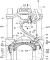
- FIG. 8 is a cross-sectional view taken along arrow 8-8 in FIG. 4 showing the second clamp part.
- FIG. 9 is a cross-sectional view taken along arrow 9-9 in FIG. 4 showing a third clamp portion.
- It is a perspective view of the 1st stay which supports the 1st clamp part.
- It is a perspective view of the holding metal fitting which comprises the 2nd clamp part. It is the principal part rear view of the vehicle which looked at the bottom bridge and the front fork which show the example of rocking
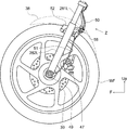
- FIG. 1 is a left side view of a motorcycle that is a saddle-ride type vehicle according to an embodiment of the present invention
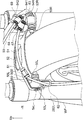
- FIG. 2 is an enlarged view of a main part of FIG. 1
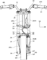
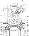
- FIG. 3 is a rear view of FIG. 2 showing a front fork and a front wheel WF.
- the reference numeral shown with an arrow indicates the direction in the motorcycle
- the reference Fr indicates the front
- the reference Rr indicates the rear
- the reference R indicates the right
- the reference L indicates the left.
- the motorcycle 1 is equipped with a single-cylinder four-cycle water-cooled engine 2.
- the body frame 3 of the motorcycle 1 has a main frame 31 that is joined to the upper end of the head pipe 30 and extends obliquely downward and rearward, and a front end that is joined to the lower end of the head pipe 30 and obliquely lower and rearward.
- a down frame 32 extending to the seat frame 33, a seat frame 33 extending obliquely upward and rearward from the middle portion of the main frame 31, and a rear portion joined to the seat frame 33, substantially parallel to the seat frame 33 and slightly lowering forward
- the sub frame 34 is arranged, and a hanger bracket 35 joined to the rear end portion of the main frame 31 and the front end portion of the sub frame 34 and extending downward.
- Ribs 41 and 42 are provided between the seat frame 33 and the subframe 34.
- the above-described members constituting the vehicle body frame 3 are provided on the left and right sides of the vehicle body to form a pair.
- the engine 2 includes a cylinder part 21, a crank chamber 22, and a speed reducer part 23.
- An intake pipe 24 is connected to the rear portion of the cylinder portion 21, and an end portion of the intake pipe 24 communicates with the inside of the air cleaner 4.
- An exhaust pipe 25 is connected to the front part of the cylinder part 21, and the exhaust pipe 25 bypasses the lower part of the vehicle body and is connected to the muffler 5 at the rear part of the vehicle body.
- the engine 2 is coupled to and supported by the lower portions of the hanger bracket 35 and the down frame 32.
- a radiator 43 through which the cooling water of the engine 2 is circulated is attached to the down frame 32.
- a steering stem (not shown) is arranged in the head pipe 30 so as to be directed in the vertical direction, and a top bridge 26 and a bottom bridge 27 are coupled to the top and bottom of the steering stem, respectively.
- a front fork 28 is supported by the top bridge 26 and the bottom bridge 27.
- a stay 36 extends from the head pipe 30 toward the front of the vehicle body, and the headlight 7 and the meter device 8 are supported by the stay 36.
- a front wheel shaft 29 that rotatably supports the front wheel WF is provided at a lower end portion of the front fork 28.
- the steering handle 6 is attached to the upper part of the top bridge 26, and the grip 44 (the right grip 44R and the left grip 44L) and the mirror 45 are attached to the steering handle 6.
- a master cylinder 80 for a front wheel disc brake driven by hydraulic pressure is provided adjacent to the right grip 44R near the center of the vehicle body.
- a front brake lever 81 for operating the master cylinder 80 is provided adjacent to the front of the right grip 44R (see FIG. 3).
- the hanger bracket 35 joined to the vehicle body frame 3 is provided with a pivot 9 extending in the vehicle width direction, and the pivot 9 supports the front portion of the swing arm 10 so as to be swingable in the vertical direction.
- a rear wheel shaft 11 is provided at the rear end of the swing arm 10, and the rear wheel shaft 11 supports a rear wheel WR that is a driving wheel.
- a drive sprocket 37a is coupled to the output shaft 46 of the speed reducer unit 23, and a driven sprocket 37b is coupled to the rear wheel shaft 11.
- the drive chain 12 is spanned between the two sprockets, and the output of the engine 2 is output. It is transmitted to the rear wheel WR.
- the swing arm 10 is supported at the front end by the pivot 9 and at the middle by the cushion unit 13.
- the cushion unit 13 is connected to the swing arm 10 and the vehicle body frame 3 (here, the hanger bracket 35) between the pivot 9 of the swing arm 10 and the rear wheel WR.
- the upper end portion of the cushion unit 13 is supported by the hanger bracket 35 in front of the battery 19, and the lower end portion is connected to the swing arm 10 via a link mechanism 14 disposed below the swing arm 10. That is, it is connected to the stay 15 that is joined to the swing arm 10 and projects downward.
- the fuel tank 16 is disposed at the front part on the main frame 31 and the seat frame 33, the occupant seat 17 is disposed at the rear part, and the air cleaner 4 is disposed at the front lower side of the occupant seat 17.
- the rear fender 18 is supported by the seat frame 33 and the rear frame frame 34, and extends rearward from the vicinity of the upper portion of the hanger bracket 35.
- the rear fender 18 is located above the rear wheel WR and functions as a mudguard that prevents mud and water from scattering, and the upper part is formed in a box shape and includes at least a battery 19 storage part. Used as (article storage unit).
- a rear lamp unit 48 is provided behind the occupant seat 17.
- the front fork 28 includes an inner tube 281 connected to each other at the upper and lower portions by the top bridge 26 and the bottom bridge 27, and an outer tube 282 into which the lower portion of the inner tube 281 is slidably fitted.
- the inner tube 281 includes a right inner tube 281R positioned on the right front side of the head pipe 30 and a left inner tube 281L positioned on the left front side of the head pipe 30.
- the outer tube 282 includes a right outer tube 282R that supports the front wheel WF on the right side. It consists of a left outer tube 282L that supports the front wheel WF on the left side.
- the right outer tube 282R and the left outer tube 282L are connected to each other by a fender bracket 52.
- a front wheel brake disk (hereinafter simply referred to as “disk”) 39 and a brake caliper 47 constituting the front wheel disk brake 40 are provided on the right side of the front wheel WF.
- the disc 39 is coupled to the wheel of the rear wheel WF, and the brake caliper 47 is fixed to the right outer tube 282R of the front fork 28.
- a brake hose 50 is drawn upward from the brake caliper 47 and connected to a master cylinder 80 attached to the steering handle 6.
- an electric wheel speed sensor 49 that detects the rotational speed of the front wheel WF is provided.
- a harness 51 including a power supply line for supplying power to the wheel speed sensor 49 and obtaining a speed detection signal, a ground line (GND), and a signal line is drawn upward from the wheel speed sensor 49, and is illustrated in the meter device 8. Not connected to the sensor output receiving unit.
- the wheel speed sensor 49 only needs to detect the rotation of the front wheel WF, and the application is not limited. For example, the speed of the vehicle is calculated based on the detection output of the wheel speed sensor 49 and displayed on the speed meter in the meter device 8, but is used as a sensor for engine control or ABS (Anti-lock-Brake System). It may be.
- the harness 51 routed upward along the left outer tube 282L is fixed to the first clamp portion 57 attached to the upper portion of the left outer tube 282L, and is guided to the right outer tube 282R side by the first clamp portion 57. .
- the harness 51 guided to the right outer tube 282R side is fixed to the second clamp portion 58 attached to the upper portion of the right outer tube 282R, and the routing direction is changed to the upper inner side.
- the brake hose 50 routed upward along the right outer tube 282R is fixed to the second clamp portion 58 and routed upward inward.
- the harness 51 is bundled with the brake hose 50 so that the harness 51 whose direction is changed upward is routed along the brake hose 50 at least between the second clamp portion 58 and the bottom bridge 27. It is done.
- the harness 51 and the brake hose 50 bundled by the second clamp part 58 are fixed to the third clamp part 59 attached to the bottom bridge 27.
- the second clamp part 58 and the third clamp part are formed so that the harness 51 and the brake hose 50 can project to the left of the vehicle body between the second clamp part 57 and the third clamp part 59 to form the swing part B1.
- the fixing position of the harness 51 and the brake hose 50 with respect to 59 or the directing direction of the harness 51 and the brake hose 50 by the second clamp part 58 and the third clamp part 59 is set.
- the swing part B1 is flexibly changed in curvature. This is effective for ensuring a sufficient length.
- the brake hose 50 and the harness 51 are routed substantially along the right inner tube 281R and connected to the master cylinder 80 and the meter device 8, respectively.
- the harness 51 and the brake hose 50 swing between the second clamp part 58 and the third clamp part 59 in the left-right direction of the vehicle body according to the expansion and contraction of the front fork 28.
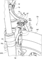
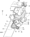
- FIG. 4 is a rear view of the main part of the vehicle viewed from the Z direction orthogonal to the bottom bridge 27 and the front fork 28, and
- FIG. 5 is a perspective view of the main part of the vehicle when the bottom bridge 27 and the front fork 28 are viewed from the lower left of the vehicle body.
- FIG. 7 is a perspective view of the main part of the vehicle when the bottom bridge 27 and the front fork 28 are viewed from the upper left of the vehicle body
- FIG. 7 is a perspective view of the main part of the vehicle when the bottom bridge 27 and the front fork 28 are viewed from the upper left rear of the vehicle body
- FIG. 4 is a sectional view taken along the line 8-8 in FIG. 4 showing the clamp part 58
- FIG. 9 is a sectional view taken along the line 9-9 in FIG.
- a fender bracket 52 for connecting the right outer tube 282R and the left outer tube 282L is provided.
- the fender bracket 52 straddles the upper part of the front wheel WF, and the right and left ends of the right and left bosses 53R and 53L project from the right outer tube 282R and the left outer tube 282L in the front-rear direction from bolts 54 and nuts 55, respectively. Are joined by a fastening member.
- Rubber bushings 56R and 56L are interposed between the right boss 53R and the left boss 53L and the left and right ends of the fender bracket 52, and the front fender 38 together with the fender bracket 52 via the rubber bushings 56R and 56L It is attached to the outer tube 282R and the left outer tube 282L.
- the first clamp portion 57 provided on the upper portion of the left outer tube 282L is in contact with the outer side in the vehicle width direction of the left boss 53L (the left side in the drawing in FIG. 4) and is fixed by a bolt 54L and a nut 55L.
- first stay (Hereinafter referred to as “first stay”) 60 and a cylindrical grommet 61 made of rubber or resin supported by the first stay 60.
- the first stay 60 includes an attachment portion 601 attached to the left boss 53 ⁇ / b> L, and a harness first clamp 602 formed in an annular shape along the outer periphery of the grommet 61 in order to hold the grommet 61.
- the harness first clamp 602 is disposed so as to hold the grommet 61 at a position deviated from the center to the right side at the upper rear of the left outer tube 282L.
- the harness first clamp 602 is arranged so that the harness 51 to be held is directed to the second clamp portion 58 on the right side of the clamp 602 and directed downward along the left outer tube 282L on the left side of the harness first clamp 602. It is arranged on the right side, that is, on the left side.
- the harness 51 held by the grommet 61 is gently arced along the left outer tube 282L at the lower end of the mounting portion 601 of the first stay 60, and is routed without protruding from the left outer tube 282L to the left side.
- the harness guide 62 is welded as described above.
- the harness guide 62 is made of a metal wire (for example, a steel wire) formed in an annular shape. The shape of the first stay 60 will be further described later with reference to FIG.
- the second clamp portion 58 provided on the upper portion of the right outer tube 282R is a second clamp portion stay (hereinafter referred to as “second stay”) that is in contact with the outside of the right boss 53R, that is, the right side and is fixed by a bolt 54R and a nut 55R. 63), a presser fitting 64 welded to the second stay 63, and three grommets 67, 68, and 69 held by the second stay 63 by the presser fitting 64.
- Grommets 67 and 68 hold the harness 51 and are the same as or equivalent to the grommet 61 of the first clamp portion 57.
- the grommet 69 is formed in a size larger than the grommets 67 and 68 for the harness 51 so that the brake hose 50 can be held.
- the second stay 63 includes an attachment portion 631 that is attached to the right boss 53R with a bolt 54R and a nut 55R, and the harness pressing metal 64 welded to the second stay 63 is an outer periphery of the grommets 67 and 68 through which the harness 51 is passed.
- a harness second clamp 641 and a harness third clamp 642 (second harness fixing means) are formed as first harness fixing means that are curved so as to be along substantially half of the circumference.
- the presser fitting 64 is provided with a first hose clamp 643 as a first hose fixing means formed in an annular shape along the outer periphery of the grommet 69.
- the presser fitting 64 is coupled to each other by a bolt 70 that passes through the presser fitting 64 and the second stay 63 and a nut 71 that is screwed into the bolt 70.
- the harness second clamp 641, the harness third clamp 642, and the hose first clamp 643 are at a position deviated to the left from the center of the right outer tube 282 ⁇ / b> R at the upper rear of the right outer tube 282 ⁇ / b> R.
- the harness second clamp 641 is arranged so that the harness 51 to be held is directed to the first clamp portion 57 on the left side of the harness second clamp 641 and the orientation direction of the harness 51 is set to the upper left side on the right side of the harness second clamp 641. It is placed in a right-down or left-up direction so that it turns.
- the harness third clamp 642 as the second harness fixing means is arranged to rise to the left, that is, to the right so that the harness 51 that is turned by the harness second clamp 641 and is directed to the upper left side is routed to the left side as it is. Is done.
- the inclination angle (angle from the horizontal) of the third harness clamp 642 is larger than that of the second harness clamp 641. That is, the harness 51 is routed upwards above the second clamp portion 58.
- the first hose clamp 643 is disposed substantially parallel to the harness third clamp 642 and adjacent to the rear of the harness third clamp 642. Therefore, the harness 51 is routed behind the brake hose 50 (rear side of the vehicle body) along the brake hose 50 above the second clamp portion 58.
- the harness 51 held by the harness second clamp 641 and the harness third clamp 642 is used to supply a relatively small current that supplies power to the wheel speed sensor 49 and detects a signal.
- the electric wires include a plus voltage line 511, a ground line 512, and a signal line 513, which are covered with a vinyl jacket 514, and have low rigidity and flexibility.
- the brake hose 50 held by the first hose clamp 643 includes a protector tube 501 and a hose body 502 accommodated in the protector tube 501.
- the outer diameter of the brake hose 50 (the outer diameter of the protector tube 501) is larger than the outer diameter of the harness 51 (the outer diameter of the jacket 514).
- the harness 51 By arranging the harness 51 so as to be hidden behind the brake hose 50, it is possible to make the harness 51 difficult to get dirty from dust or water from the front. Since the harness 51 has a smaller outer diameter than the brake hose 50, the range of free deformation is wide and the deformation range is difficult to predict, but the minimum curvature radius of the brake hose 50 is smaller than that of the harness 51. For example, the minimum curvature radius of the harness 51 is 30 mm, and the minimum curvature radius of the brake hose 50 is 25 mm.
- the harness 51 is not limited to be routed so as to be hidden behind the brake hose 50, and the curvature radius of the harness 51 in the swing part B1 is set according to the minimum curvature radius of each brake hose.
- the length of the harness 51 can be made longer than the length of the brake hose 50 so that the radius of curvature of 50 becomes large.
- the harness 51 can be routed with a relatively large radius and allowance in the swinging portion B1.
- FIG. 12 is a rear view of the main part of the vehicle when the bottom bridge and the front fork are viewed from the rear, and shows an example of the swinging part B1 in which the length of the harness 51 is longer than the length of the brake hose 50.
- the same reference numerals as those in FIG. 4 denote the same or equivalent parts.
- the harness 51 is not hidden behind the brake hose 50, but can be routed with a larger radius of curvature within the allowable range.
- a boss 271 for the third clamp part 59 protrudes downward from the bottom bridge 27, and a female screw 272 is formed on the boss 271.
- the third clamp portion 59 has a stay (hereinafter referred to as “third stay”) 73 attached to the lower surface of the bottom bridge 27 by a bolt 72 screwed into the female screw 272 from below. Further, the third clamp portion 59 has a holding metal fitting 74 that fixes the harness 51 and the brake hose 50 to the third stay 73. The holding metal fitting 74 is attached to the third stay 73 using a bolt 75 and a nut 76. Combined.
- the hose second clamp 741 as a second hose fixing means that comes into contact with the outer periphery of the grommet 77 and the front fork are parallel to the brake hose 50.
- a harness fourth clamp 742 is provided as third harness fixing means that contacts the outer periphery of the grommet 78. That is, the hose second clamp 741 and the harness fourth clamp 742 are arranged on the lower left side of the bottom bridge 27 via the stay 73 by the holding metal fitting 74 that is an integral part.
- the second hose clamp 741 holds the brake hose 50 in the vehicle width direction
- the fourth harness clamp 742 holds the harness 51 in the vehicle width direction behind the brake hose 50.
- the second hose clamp 741 and the fourth harness clamp 742 are arranged substantially horizontally so as to be oriented in the vehicle width direction.
- the brake hose 50 can be supported on the vehicle body by a hose band 90, a wire 91, or the like that is a guide portion between the brake cylinder 50 and the master cylinder 80 above the third clamp portion 59.
- the harness 51 can be supported by a bracket 30a (see FIG. 9) or the like that extends upward from the head pipe 30 using the band 92 above the third clamp portion 59.
- a presser fitting (wire) 93 that holds a main harness (not shown) that electrically connects the headlight 7, the meter device 8, the battery 19, an ECU (not shown) and the like to the vehicle body rear end of the third stay 73.
- the parts are welded.
- FIG. 10 is a perspective view of the first stay 60.
- the first stay 60 is formed by bending a plate member (for example, a metal plate).
- the first stay 60 is a plate member forming the attachment portion 601. Both end portions 60E and 60F are separated from each other and opened, and the both end portions 60E and 60F are overlapped with each other while being attached to the left boss 53L, and the attachment portion 601 is closed.
- through holes 60c and 60d through which bolts 54L can be passed are formed, respectively.
- FIG. 10 is a perspective view of the grommet 61 held by the harness first clamp 602 together with the first stay 60.
- the harness 51 is passed through the grommet 61, and the grommet 61 is held by the harness first clamp 602 in this state.
- the grommet 61 is a cylindrical body having flanges 611 at both ends, and is formed of an elastic member such as rubber or resin. Therefore, when the grommet 61 is pressed around the harness 51, the harness 51 is tightened by the repulsive force or elasticity of rubber, and the flange 611 contacts the end surface of the first stay 60. Is fixed.
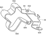
- FIG. 11 is a perspective view of the presser fitting 64 that constitutes the second clamp portion 58.
- a holding metal fitting 64 whose one end is welded to the second stay 63 includes a harness second clamp 641 that is curved with a curvature matching the outer diameter of the outer sheath of the harness 51, a harness third clamp 642,
- the holding metal fitting 64 including the first hose clamp 643 and the second harness clamp 641, the third harness clamp 642, and the first hose clamp 643 can be integrally formed of one steel plate.
- the grommets 67 and 68 can be held by the integrated holding metal fitting 64 to fix the position of the harness 51, and the grommet 69 for the hose can be collectively supported.
- the presser fitting 64 and the second stay 63 welded to each other have a through hole 632 that passes through the presser fixture 64 and the second stay 63, and is formed at the other end of the through hole 632 and the presser fixture 64. Both ends of the presser fitting 64 are tightened using bolts 70 and nuts 71 that pass through the through holes 644, and the grommets 67, 68, and 69 are supported at desired positions.
- the second stay 63 is formed with a through hole 631 through which a bolt 55L for attaching to the left boss 53L of the left outer tube 282L can be passed.
- the harness 51 fixed by the first clamp portion 57 is guided to the second clamp portion 58 on the opposite side of the first clamp portion 57 across the front wheel WF, and once in the second clamp portion 58. It can be fixed and bundled with the brake hose 51. Then, the harness 51 and the brake hose 50 that are bundled together are formed between the front fender 38 and the bottom bridge 27 so as to form a swinging portion B1 that is curved inward in the vehicle width direction, A third clamp part 59 is configured.
- the swinging portion B1 is displaced mainly in the vehicle width direction between the left outer tube 282L and the right outer tube 282R in response to the expansion / contraction operation of the front fork 28, thereby reducing the displacement in the longitudinal direction of the vehicle body.
- the harness 51 is bundled with the brake hose 50 to increase the rigidity, the amount of displacement of the swinging portion B1 in the longitudinal direction of the vehicle body can be generally predicted. Therefore, when the front fork 28 is steered, interference with the adjacent member can be prevented even if the distance between the front fork 28 and the rear adjacent member such as the radiator 43 and the exhaust pipe 25 is shortened with high accuracy. As a result, an efficient layout can be designed without increasing the size of the motorcycle 1.
- the present invention is not limited to the technical idea described in the claims, but is modified to the saddle-ride type vehicle (not only a saddle-ride type two-wheel vehicle but also a saddle-ride type tricycle or four-wheel vehicle).
- the first to third stays 60, 63, 73 constituting the first to third clamp parts 57, 58, 59 hold the harness 51 and the brake hose 50, and the first to third clamp parts 57, If the harness 51 and the brake hose 50 are oriented in the above direction at 58 and 59, the shape is arbitrary.
- the second and third clamp portions 58 and 59 are configured such that the harness 51 and the brake hose 50 are attached to the second stay 63 and the third stay 73 with a common metal fitting. You may attach using a metal fitting.
- harness second holding part (first Harness fixing means), 642 ... Harness 3 Holding part (second harness fixing means), 643 ... hose first holding part (first hose fixing means), 741 ... hose second holding part (second hose fixing means), 742 ... harness fourth holding part (Third harness fixing means)
Landscapes
- Engineering & Computer Science (AREA)
- Mechanical Engineering (AREA)
- General Engineering & Computer Science (AREA)
- Physics & Mathematics (AREA)
- Fluid Mechanics (AREA)
- Motorcycle And Bicycle Frame (AREA)
- Valves And Accessory Devices For Braking Systems (AREA)
Priority Applications (7)
| Application Number | Priority Date | Filing Date | Title |
|---|---|---|---|
| EP13764318.5A EP2829463B1 (de) | 2012-03-21 | 2013-02-08 | Sattelfahrzeug |
| ES13764318.5T ES2622894T3 (es) | 2012-03-21 | 2013-02-08 | Vehículo de sillín |
| CN201380015356.6A CN104203737B (zh) | 2012-03-21 | 2013-02-08 | 跨乘型车辆 |
| JP2014506073A JP5971775B2 (ja) | 2012-03-21 | 2013-02-08 | 鞍乗り型車両 |
| BR112014022906-6A BR112014022906B1 (pt) | 2012-03-21 | 2013-02-08 | veículo com selim |
| KR1020147029310A KR101634029B1 (ko) | 2012-03-21 | 2013-02-08 | 안장형 차량 |
| US14/385,841 US9187049B2 (en) | 2012-03-21 | 2013-02-08 | Saddled vehicle |
Applications Claiming Priority (2)
| Application Number | Priority Date | Filing Date | Title |
|---|---|---|---|
| JP2012063874 | 2012-03-21 | ||
| JP2012-063874 | 2012-03-21 |
Publications (1)
| Publication Number | Publication Date |
|---|---|
| WO2013140891A1 true WO2013140891A1 (ja) | 2013-09-26 |
Family
ID=49222356
Family Applications (1)
| Application Number | Title | Priority Date | Filing Date |
|---|---|---|---|
| PCT/JP2013/053128 WO2013140891A1 (ja) | 2012-03-21 | 2013-02-08 | 鞍乗り型車両 |
Country Status (8)
| Country | Link |
|---|---|
| US (1) | US9187049B2 (de) |
| EP (1) | EP2829463B1 (de) |
| JP (1) | JP5971775B2 (de) |
| KR (1) | KR101634029B1 (de) |
| CN (1) | CN104203737B (de) |
| BR (1) | BR112014022906B1 (de) |
| ES (1) | ES2622894T3 (de) |
| WO (1) | WO2013140891A1 (de) |
Cited By (10)
| Publication number | Priority date | Publication date | Assignee | Title |
|---|---|---|---|---|
| CN105024316A (zh) * | 2014-04-21 | 2015-11-04 | 光阳工业股份有限公司 | 摩托车导线的保护装置 |
| JP2017047763A (ja) * | 2015-09-01 | 2017-03-09 | ヤマハ発動機株式会社 | 鞍乗型車両 |
| WO2018029734A1 (ja) * | 2016-08-08 | 2018-02-15 | 本田技研工業株式会社 | 車両 |
| WO2018124099A1 (ja) * | 2016-12-28 | 2018-07-05 | ヤマハ発動機株式会社 | 鞍乗型車両 |
| JP2019051779A (ja) * | 2017-09-14 | 2019-04-04 | 川崎重工業株式会社 | 自動二輪車 |
| DE112018004939T5 (de) | 2017-09-07 | 2020-06-04 | Honda Motor Co., Ltd. | Frontstruktur für ein fahrzeug vom satteltyp |
| JP2020104838A (ja) * | 2018-12-27 | 2020-07-09 | 本田技研工業株式会社 | 鞍乗り型車両 |
| JP2020164101A (ja) * | 2019-03-29 | 2020-10-08 | 本田技研工業株式会社 | 鞍乗り型車両 |
| US20220048594A1 (en) * | 2020-08-12 | 2022-02-17 | Sun Race Sturmey-Archer Inc. | Structure for locking the cable of bicycle |
| JP7457076B1 (ja) | 2022-09-09 | 2024-03-27 | 本田技研工業株式会社 | 鞍乗型車両 |
Families Citing this family (18)
| Publication number | Priority date | Publication date | Assignee | Title |
|---|---|---|---|---|
| BR112015032716A2 (pt) * | 2013-07-01 | 2017-07-25 | Yamaha Motor Co Ltd | veículo equipado com uma armação do chassi capaz de inclinar e duas rodas dianteiras |
| JP6140569B2 (ja) * | 2013-08-08 | 2017-05-31 | 本田技研工業株式会社 | 鞍乗り型車両 |
| US10272968B2 (en) | 2015-03-20 | 2019-04-30 | Honda Motor Co., Ltd. | Saddle-riding-type vehicle sensor unit attachment structure |
| KR101582277B1 (ko) * | 2015-06-16 | 2016-01-04 | 주식회사 케이지씨코리아 | 자동차용 모노블럭 브레이크캘리퍼의 제조방법 |
| JP2017065533A (ja) * | 2015-09-30 | 2017-04-06 | ヤマハ発動機株式会社 | 車両 |
| EP3225526B1 (de) * | 2016-03-28 | 2019-10-23 | Honda Motor Co., Ltd. | Sattelfahrzeug-kabelhaltestruktur |
| WO2018062421A1 (ja) * | 2016-09-30 | 2018-04-05 | 本田技研工業株式会社 | 鞍乗り型車両の連動ブレーキ支持構造 |
| JP2018058455A (ja) * | 2016-10-04 | 2018-04-12 | ヤマハ発動機株式会社 | 鞍乗型車両 |
| EP3330166B1 (de) * | 2016-12-05 | 2019-03-06 | Yamaha Hatsudoki Kabushiki Kaisha | Grätschsitzfahrzeug |
| CN107089287A (zh) * | 2017-04-06 | 2017-08-25 | 桐乡市洲泉振兴五金塑料制品厂 | 一种摩托车用线束连接架 |
| JP7311240B2 (ja) * | 2017-10-06 | 2023-07-19 | 株式会社シマノ | 自転車用無線ユニット |
| JP2019084965A (ja) * | 2017-11-07 | 2019-06-06 | ヤマハ発動機株式会社 | 鞍乗型車両 |
| EP3705389A4 (de) * | 2018-02-05 | 2021-03-03 | Honda Motor Co., Ltd. | Sattelfahrzeug |
| EP3835189B1 (de) * | 2018-08-09 | 2023-04-12 | Honda Motor Co., Ltd. | Sattelfahrzeug |
| CN111717313B (zh) * | 2019-03-19 | 2022-05-10 | Tvs电机股份有限公司 | 鞍座型车辆 |
| JP7283362B2 (ja) * | 2019-11-29 | 2023-05-30 | スズキ株式会社 | 鞍乗型車両 |
| JP7004121B2 (ja) * | 2020-02-20 | 2022-02-10 | 住友電装株式会社 | ワイヤーハーネス及びワイヤーハーネスの配索構造 |
| CN117341602A (zh) * | 2020-02-20 | 2024-01-05 | 住友电装株式会社 | 线束及线束的布设结构 |
Citations (4)
| Publication number | Priority date | Publication date | Assignee | Title |
|---|---|---|---|---|
| JP2001165949A (ja) | 1999-09-30 | 2001-06-22 | Honda Motor Co Ltd | 車輪速度検出装置 |
| JP2002029395A (ja) * | 2000-07-19 | 2002-01-29 | Honda Motor Co Ltd | 車輪速度検出装置の取付構造 |
| JP2005082024A (ja) * | 2003-09-09 | 2005-03-31 | Honda Motor Co Ltd | ブレーキホースの支持構造 |
| JP2007076555A (ja) * | 2005-09-15 | 2007-03-29 | Kawasaki Heavy Ind Ltd | 自動二輪車 |
Family Cites Families (7)
| Publication number | Priority date | Publication date | Assignee | Title |
|---|---|---|---|---|
| JPS60252084A (ja) * | 1984-05-26 | 1985-12-12 | 本田技研工業株式会社 | 車輪角減速度センサの支持・駆動装置 |
| EP1783018A1 (de) * | 2005-11-04 | 2007-05-09 | Kwang Yang Motor Co., Ltd. | Vorderrahmenaufbau für Motorrad |
| CN201077495Y (zh) * | 2007-06-05 | 2008-06-25 | 江门市大长江集团有限公司 | 一种摩托车速度传感器线束的固定结构 |
| JP5172419B2 (ja) * | 2008-03-28 | 2013-03-27 | 本田技研工業株式会社 | 自動二輪車 |
| JP5129672B2 (ja) * | 2008-07-07 | 2013-01-30 | 本田技研工業株式会社 | 自動二輪車の車体カバー構造 |
| JP5300142B2 (ja) * | 2009-08-31 | 2013-09-25 | 本田技研工業株式会社 | 自動二輪車 |
| JP5969179B2 (ja) * | 2011-07-31 | 2016-08-17 | 本田技研工業株式会社 | 車輪速センサの取付構造 |
-
2013
- 2013-02-08 US US14/385,841 patent/US9187049B2/en active Active
- 2013-02-08 ES ES13764318.5T patent/ES2622894T3/es active Active
- 2013-02-08 KR KR1020147029310A patent/KR101634029B1/ko active IP Right Grant
- 2013-02-08 CN CN201380015356.6A patent/CN104203737B/zh not_active Expired - Fee Related
- 2013-02-08 JP JP2014506073A patent/JP5971775B2/ja active Active
- 2013-02-08 EP EP13764318.5A patent/EP2829463B1/de not_active Not-in-force
- 2013-02-08 BR BR112014022906-6A patent/BR112014022906B1/pt not_active IP Right Cessation
- 2013-02-08 WO PCT/JP2013/053128 patent/WO2013140891A1/ja active Application Filing
Patent Citations (4)
| Publication number | Priority date | Publication date | Assignee | Title |
|---|---|---|---|---|
| JP2001165949A (ja) | 1999-09-30 | 2001-06-22 | Honda Motor Co Ltd | 車輪速度検出装置 |
| JP2002029395A (ja) * | 2000-07-19 | 2002-01-29 | Honda Motor Co Ltd | 車輪速度検出装置の取付構造 |
| JP2005082024A (ja) * | 2003-09-09 | 2005-03-31 | Honda Motor Co Ltd | ブレーキホースの支持構造 |
| JP2007076555A (ja) * | 2005-09-15 | 2007-03-29 | Kawasaki Heavy Ind Ltd | 自動二輪車 |
Non-Patent Citations (1)
| Title |
|---|
| See also references of EP2829463A4 |
Cited By (13)
| Publication number | Priority date | Publication date | Assignee | Title |
|---|---|---|---|---|
| CN105024316A (zh) * | 2014-04-21 | 2015-11-04 | 光阳工业股份有限公司 | 摩托车导线的保护装置 |
| JP2017047763A (ja) * | 2015-09-01 | 2017-03-09 | ヤマハ発動機株式会社 | 鞍乗型車両 |
| WO2018029734A1 (ja) * | 2016-08-08 | 2018-02-15 | 本田技研工業株式会社 | 車両 |
| JPWO2018029734A1 (ja) * | 2016-08-08 | 2019-03-14 | 本田技研工業株式会社 | 車両 |
| WO2018124099A1 (ja) * | 2016-12-28 | 2018-07-05 | ヤマハ発動機株式会社 | 鞍乗型車両 |
| DE112018004939T5 (de) | 2017-09-07 | 2020-06-04 | Honda Motor Co., Ltd. | Frontstruktur für ein fahrzeug vom satteltyp |
| JP2019051779A (ja) * | 2017-09-14 | 2019-04-04 | 川崎重工業株式会社 | 自動二輪車 |
| JP2020104838A (ja) * | 2018-12-27 | 2020-07-09 | 本田技研工業株式会社 | 鞍乗り型車両 |
| JP7113797B2 (ja) | 2018-12-27 | 2022-08-05 | 本田技研工業株式会社 | 鞍乗り型車両 |
| JP2020164101A (ja) * | 2019-03-29 | 2020-10-08 | 本田技研工業株式会社 | 鞍乗り型車両 |
| US20220048594A1 (en) * | 2020-08-12 | 2022-02-17 | Sun Race Sturmey-Archer Inc. | Structure for locking the cable of bicycle |
| US11673624B2 (en) * | 2020-08-12 | 2023-06-13 | Sun Race Sturmey-Archer Inc. | Structure for locking the cable of bicycle |
| JP7457076B1 (ja) | 2022-09-09 | 2024-03-27 | 本田技研工業株式会社 | 鞍乗型車両 |
Also Published As
| Publication number | Publication date |
|---|---|
| KR101634029B1 (ko) | 2016-06-27 |
| EP2829463A1 (de) | 2015-01-28 |
| JPWO2013140891A1 (ja) | 2015-08-03 |
| BR112014022906B1 (pt) | 2020-11-24 |
| ES2622894T3 (es) | 2017-07-07 |
| US9187049B2 (en) | 2015-11-17 |
| US20150076790A1 (en) | 2015-03-19 |
| KR20140139003A (ko) | 2014-12-04 |
| EP2829463A4 (de) | 2015-10-21 |
| CN104203737A (zh) | 2014-12-10 |
| JP5971775B2 (ja) | 2016-08-17 |
| CN104203737B (zh) | 2017-03-01 |
| EP2829463B1 (de) | 2017-04-05 |
Similar Documents
| Publication | Publication Date | Title |
|---|---|---|
| JP5971775B2 (ja) | 鞍乗り型車両 | |
| US8627916B2 (en) | Saddle riding type vehicle | |
| JP5871382B2 (ja) | 鞍乗型車両のハーネス配策構造 | |
| JP2014177928A (ja) | 鞍乗型車両 | |
| JP2009234424A (ja) | 鞍乗り型車両のハーネス保持構造 | |
| JP5697189B2 (ja) | 鞍乗り型車両 | |
| US7104585B2 (en) | Forward disposed part installation structure of motorcycle | |
| JP5607016B2 (ja) | 自動二輪車におけるガードパイプの取付け構造 | |
| CN110015368B (zh) | 鞍座式骑乘车辆 | |
| JP2015227101A (ja) | 鞍乗型車両 | |
| JP6790045B2 (ja) | 鞍乗型車両 | |
| EP3536594B1 (de) | Befestigung der hydraulik- und motorsteuereinheiten eines grätschsitzfahrzeugs | |
| US10442491B2 (en) | Straddle-type vehicle | |
| WO2011117919A1 (ja) | 鞍乗り型車両の吸気系の配置構造 | |
| JP2017121924A (ja) | 鞍乗り型車両 | |
| JP6564129B2 (ja) | 灯火器装置及び鞍乗型車両 | |
| US11072393B2 (en) | Transmission for saddled vehicle | |
| JP7343638B1 (ja) | 鞍乗型車両 | |
| JP7096381B2 (ja) | 鞍乗型車両 | |
| JP7210624B2 (ja) | 鞍乗型車両 | |
| JP2013112258A (ja) | 鞍乗り型車両の灯火器組立体 | |
| JP7061102B2 (ja) | 鞍乗型車両 | |
| JP2023019172A (ja) | 鞍乗型車両のメータブラケット | |
| JP2022155677A (ja) | 鞍乗型車両 | |
| JP2021054263A (ja) | ウインカ装置 |
Legal Events
| Date | Code | Title | Description |
|---|---|---|---|
| 121 | Ep: the epo has been informed by wipo that ep was designated in this application |
Ref document number: 13764318 Country of ref document: EP Kind code of ref document: A1 |
|
| ENP | Entry into the national phase |
Ref document number: 2014506073 Country of ref document: JP Kind code of ref document: A |
|
| REEP | Request for entry into the european phase |
Ref document number: 2013764318 Country of ref document: EP |
|
| WWE | Wipo information: entry into national phase |
Ref document number: 2013764318 Country of ref document: EP |
|
| WWE | Wipo information: entry into national phase |
Ref document number: 14385841 Country of ref document: US |
|
| ENP | Entry into the national phase |
Ref document number: 20147029310 Country of ref document: KR Kind code of ref document: A |
|
| REG | Reference to national code |
Ref country code: BR Ref legal event code: B01A Ref document number: 112014022906 Country of ref document: BR |
|
| NENP | Non-entry into the national phase |
Ref country code: DE |
|
| ENP | Entry into the national phase |
Ref document number: 112014022906 Country of ref document: BR Kind code of ref document: A2 Effective date: 20140916 |