WO2012111116A1 - リチウムイオン二次電池及びその製造方法 - Google Patents
リチウムイオン二次電池及びその製造方法 Download PDFInfo
- Publication number
- WO2012111116A1 WO2012111116A1 PCT/JP2011/053295 JP2011053295W WO2012111116A1 WO 2012111116 A1 WO2012111116 A1 WO 2012111116A1 JP 2011053295 W JP2011053295 W JP 2011053295W WO 2012111116 A1 WO2012111116 A1 WO 2012111116A1
- Authority
- WO
- WIPO (PCT)
- Prior art keywords
- positive electrode
- active material
- electrode active
- lithium ion
- ion secondary
- Prior art date
- Legal status (The legal status is an assumption and is not a legal conclusion. Google has not performed a legal analysis and makes no representation as to the accuracy of the status listed.)
- Ceased
Links
Images







Classifications
-
- H—ELECTRICITY
- H01—ELECTRIC ELEMENTS
- H01M—PROCESSES OR MEANS, e.g. BATTERIES, FOR THE DIRECT CONVERSION OF CHEMICAL ENERGY INTO ELECTRICAL ENERGY
- H01M4/00—Electrodes
- H01M4/02—Electrodes composed of, or comprising, active material
- H01M4/13—Electrodes for accumulators with non-aqueous electrolyte, e.g. for lithium-accumulators; Processes of manufacture thereof
-
- H—ELECTRICITY
- H01—ELECTRIC ELEMENTS
- H01M—PROCESSES OR MEANS, e.g. BATTERIES, FOR THE DIRECT CONVERSION OF CHEMICAL ENERGY INTO ELECTRICAL ENERGY
- H01M4/00—Electrodes
- H01M4/02—Electrodes composed of, or comprising, active material
- H01M4/13—Electrodes for accumulators with non-aqueous electrolyte, e.g. for lithium-accumulators; Processes of manufacture thereof
- H01M4/131—Electrodes based on mixed oxides or hydroxides, or on mixtures of oxides or hydroxides, e.g. LiCoOx
-
- H—ELECTRICITY
- H01—ELECTRIC ELEMENTS
- H01M—PROCESSES OR MEANS, e.g. BATTERIES, FOR THE DIRECT CONVERSION OF CHEMICAL ENERGY INTO ELECTRICAL ENERGY
- H01M10/00—Secondary cells; Manufacture thereof
- H01M10/05—Accumulators with non-aqueous electrolyte
- H01M10/052—Li-accumulators
- H01M10/0525—Rocking-chair batteries, i.e. batteries with lithium insertion or intercalation in both electrodes; Lithium-ion batteries
-
- H—ELECTRICITY
- H01—ELECTRIC ELEMENTS
- H01M—PROCESSES OR MEANS, e.g. BATTERIES, FOR THE DIRECT CONVERSION OF CHEMICAL ENERGY INTO ELECTRICAL ENERGY
- H01M4/00—Electrodes
- H01M4/02—Electrodes composed of, or comprising, active material
- H01M4/13—Electrodes for accumulators with non-aqueous electrolyte, e.g. for lithium-accumulators; Processes of manufacture thereof
- H01M4/139—Processes of manufacture
- H01M4/1391—Processes of manufacture of electrodes based on mixed oxides or hydroxides, or on mixtures of oxides or hydroxides, e.g. LiCoOx
-
- H—ELECTRICITY
- H01—ELECTRIC ELEMENTS
- H01M—PROCESSES OR MEANS, e.g. BATTERIES, FOR THE DIRECT CONVERSION OF CHEMICAL ENERGY INTO ELECTRICAL ENERGY
- H01M4/00—Electrodes
- H01M4/02—Electrodes composed of, or comprising, active material
- H01M4/36—Selection of substances as active materials, active masses, active liquids
- H01M4/48—Selection of substances as active materials, active masses, active liquids of inorganic oxides or hydroxides
- H01M4/50—Selection of substances as active materials, active masses, active liquids of inorganic oxides or hydroxides of manganese
- H01M4/505—Selection of substances as active materials, active masses, active liquids of inorganic oxides or hydroxides of manganese of mixed oxides or hydroxides containing manganese for inserting or intercalating light metals, e.g. LiMn2O4 or LiMn2OxFy
-
- H—ELECTRICITY
- H01—ELECTRIC ELEMENTS
- H01M—PROCESSES OR MEANS, e.g. BATTERIES, FOR THE DIRECT CONVERSION OF CHEMICAL ENERGY INTO ELECTRICAL ENERGY
- H01M4/00—Electrodes
- H01M4/02—Electrodes composed of, or comprising, active material
- H01M4/36—Selection of substances as active materials, active masses, active liquids
- H01M4/48—Selection of substances as active materials, active masses, active liquids of inorganic oxides or hydroxides
- H01M4/52—Selection of substances as active materials, active masses, active liquids of inorganic oxides or hydroxides of nickel, cobalt or iron
- H01M4/525—Selection of substances as active materials, active masses, active liquids of inorganic oxides or hydroxides of nickel, cobalt or iron of mixed oxides or hydroxides containing iron, cobalt or nickel for inserting or intercalating light metals, e.g. LiNiO2, LiCoO2 or LiCoOxFy
-
- H—ELECTRICITY
- H01—ELECTRIC ELEMENTS
- H01M—PROCESSES OR MEANS, e.g. BATTERIES, FOR THE DIRECT CONVERSION OF CHEMICAL ENERGY INTO ELECTRICAL ENERGY
- H01M4/00—Electrodes
- H01M4/02—Electrodes composed of, or comprising, active material
- H01M4/62—Selection of inactive substances as ingredients for active masses, e.g. binders, fillers
- H01M4/621—Binders
- H01M4/622—Binders being polymers
-
- Y—GENERAL TAGGING OF NEW TECHNOLOGICAL DEVELOPMENTS; GENERAL TAGGING OF CROSS-SECTIONAL TECHNOLOGIES SPANNING OVER SEVERAL SECTIONS OF THE IPC; TECHNICAL SUBJECTS COVERED BY FORMER USPC CROSS-REFERENCE ART COLLECTIONS [XRACs] AND DIGESTS
- Y02—TECHNOLOGIES OR APPLICATIONS FOR MITIGATION OR ADAPTATION AGAINST CLIMATE CHANGE
- Y02E—REDUCTION OF GREENHOUSE GAS [GHG] EMISSIONS, RELATED TO ENERGY GENERATION, TRANSMISSION OR DISTRIBUTION
- Y02E60/00—Enabling technologies; Technologies with a potential or indirect contribution to GHG emissions mitigation
- Y02E60/10—Energy storage using batteries
-
- Y—GENERAL TAGGING OF NEW TECHNOLOGICAL DEVELOPMENTS; GENERAL TAGGING OF CROSS-SECTIONAL TECHNOLOGIES SPANNING OVER SEVERAL SECTIONS OF THE IPC; TECHNICAL SUBJECTS COVERED BY FORMER USPC CROSS-REFERENCE ART COLLECTIONS [XRACs] AND DIGESTS
- Y02—TECHNOLOGIES OR APPLICATIONS FOR MITIGATION OR ADAPTATION AGAINST CLIMATE CHANGE
- Y02T—CLIMATE CHANGE MITIGATION TECHNOLOGIES RELATED TO TRANSPORTATION
- Y02T10/00—Road transport of goods or passengers
- Y02T10/60—Other road transportation technologies with climate change mitigation effect
- Y02T10/70—Energy storage systems for electromobility, e.g. batteries
-
- Y—GENERAL TAGGING OF NEW TECHNOLOGICAL DEVELOPMENTS; GENERAL TAGGING OF CROSS-SECTIONAL TECHNOLOGIES SPANNING OVER SEVERAL SECTIONS OF THE IPC; TECHNICAL SUBJECTS COVERED BY FORMER USPC CROSS-REFERENCE ART COLLECTIONS [XRACs] AND DIGESTS
- Y10—TECHNICAL SUBJECTS COVERED BY FORMER USPC
- Y10T—TECHNICAL SUBJECTS COVERED BY FORMER US CLASSIFICATION
- Y10T29/00—Metal working
- Y10T29/49—Method of mechanical manufacture
- Y10T29/49002—Electrical device making
- Y10T29/49108—Electric battery cell making
- Y10T29/49115—Electric battery cell making including coating or impregnating
Definitions
- the present invention relates to a lithium ion secondary battery and a manufacturing method thereof. Specifically, the present invention relates to a positive electrode having a configuration in which a positive electrode material including a positive electrode active material is held by a positive electrode current collector, and a method for manufacturing a lithium ion secondary battery including the positive electrode.
- a lithium ion secondary battery that is charged and discharged by moving lithium ions back and forth between a positive electrode and a negative electrode can be mounted on a vehicle that uses electricity as a drive source, for example, because it is lightweight and has a high energy density. The importance is increasing as a power source or a power source used for personal computers, portable terminals, and other electrical products.
- an electrode material mainly composed of a substance (electrode active material) capable of reversibly occluding and releasing lithium ions on a conductive member (electrode current collector) is layered.
- An electrode having a formed configuration hereinafter, this layered product is referred to as an “electrode mixture layer”.
- a paste-like composition in which a lithium-containing compound as a positive electrode active material, a highly conductive material powder (conductive material), a binder (binder) and the like are dispersed in a suitable solvent and kneaded (
- the paste-like composition includes a slurry-like composition and an ink-like composition.
- a positive electrode current collector for example, an aluminum material
- Patent documents 1 and 2 are mentioned as conventional technology about this kind of positive electrode.
- an aqueous solvent (specifically, water) is employed as a solvent used when preparing a paste-like composition for forming a positive electrode mixture layer.
- a solvent lithium ions may be eluted from the lithium-containing compound (positive electrode active material) into the solvent and the composition itself may exhibit strong alkalinity.
- the binder (binder) contained in the composition is decomposed, or the binder is aggregated (gelled) or the positive electrode active material is aggregated.
- Such decomposition or agglomeration of the material leads to a decrease in viscosity and adhesive strength of the paste-like composition, and further dispersibility decreases.
- the positive electrode composite having a uniform composition with a desired thickness on the positive electrode current collector is obtained. It can be difficult to form a material layer. If the thickness and composition are not uniform, the battery reactivity during charge / discharge deteriorates, and further, the internal resistance of the battery increases, which is not preferable.
- the advantage of using an aqueous solvent is that, compared to the case of using an organic solvent (for example, N-methylpyrrolidone), the organic solvent and the accompanying industrial waste can be reduced, and the equipment and processing costs for that are reduced. Since it does not occur, the environmental load can be reduced as a whole.
- a positive electrode composite material having a property capable of realizing desired battery performance even when an aqueous solvent (typically water) having a low environmental load is used and the aqueous solvent is used.
- a technique capable of forming a layer (and thus a positive electrode) is required.
- the present invention was created to solve the above-described conventional problems (requests), and the object thereof is a battery including a positive electrode formed using a composition comprising an aqueous solvent, and battery performance. It is providing the lithium ion secondary battery which is excellent in. Another object is to provide a method for producing a lithium ion secondary battery including the positive electrode disclosed herein.
- the present invention provides a method for producing a lithium ion secondary battery. That is, the method for producing a lithium ion secondary battery disclosed herein includes a step of forming a positive electrode including a positive electrode mixture layer containing a positive electrode active material on a positive electrode current collector, and a negative electrode active material on a negative electrode current collector. A step of forming a negative electrode comprising a negative electrode composite material layer, and a step of forming an electrode body by combining the formed positive electrode and negative electrode.
- the positive electrode forming step preparing a coated positive electrode active material in which the surface of the positive electrode active material is coated with a hydrophobic film; at least the coated positive electrode active material and a binder dissolved or dispersed in an aqueous solvent, Preparing a paste-like composition for forming a positive electrode mixture layer obtained by adding to an aqueous solvent and kneading; applying the prepared composition for forming a positive electrode mixture layer on the surface of the positive electrode current collector Including.
- the coated positive electrode active material in which the surface of the positive electrode active material is coated with a hydrophobic film is used, a paste-like composition for forming a positive electrode mixture layer
- a paste-like composition for forming a positive electrode mixture layer When preparing (for example) preparing, for example, a lithium transition metal composite oxide as a positive electrode active material and an aqueous solvent (for example, water), the lithium element in the positive electrode active material is incorporated into the aqueous solvent as lithium ions. Elution is suppressed.
- the prepared composition does not exhibit strong alkalinity even when an aqueous solvent is used, and the decomposition and gelation of the binder based on strong alkalinity, aggregation of the active material, the positive electrode current collector and the above composition Reaction (alkali corrosion reaction) is prevented. Therefore, according to the present invention, it is possible to manufacture a high-performance lithium ion secondary battery that prevents an increase in battery reaction resistance and a decrease in durability and has a lower environmental impact than conventional lithium ion secondary batteries. it can.
- an amphiphilic compound is used as the binder.
- the affinity between the hydrophobic coating of the coated positive electrode active material and the aqueous solvent (for example, water) is increased through the amphiphilic compound. Therefore, in the composition for forming a positive electrode mixture layer, The binder is well dispersed. It is particularly preferable to employ polyethylene oxide as the amphiphilic compound.
- the binder contained in the positive electrode mixture layer when the formed positive electrode mixture layer (total amount) is 100 mass%, the binder contained in the positive electrode mixture layer is 2 mass.
- the paste-like composition for forming a positive electrode mixture layer is prepared so as to be 5% to 5% by mass. According to this configuration, since the binder contained in the positive electrode mixture layer is in an appropriate amount, a lithium ion secondary battery with excellent performance can be manufactured.
- a coated positive electrode active material in which the surface of the positive electrode active material is coated with a water-repellent resin as the hydrophobic film is used as the coated positive electrode active material.
- the water repellent resin is a fluororesin.
- polyvinylidene fluoride has good ion permeability, the resistance of a hydrophobic coating formed using such a material is low.
- a coated positive electrode active material in which the surface of the positive electrode active material is coated with a transition metal oxide as the hydrophobic film is used as the coated positive electrode active material.
- the transition metal oxide is tungsten oxide or zirconium oxide.
- the positive electrode active material has a specific surface area based on the BET method of X [m 2 / g], and the mass A [ mg / m and the mass B [g] of the positive electrode active material, where Y / X is 5 mg / m 2 to 50 mg / m, where A / B is the oxide coating amount Y [mg / g]. 2 coated positive electrode active material is used.
- Y / X is in the above range, the positive electrode active material is sufficiently covered with the transition metal oxide, and the ion permeability in the transition metal oxide is improved.
- a secondary battery can be manufactured.
- the positive electrode active material may be represented by the general formula: Li 1 + x (Ni y Co z Mn 1-yz- ⁇ M ⁇ ) O 2 (However, 0 ⁇ x ⁇ 0.2, 0.5 ⁇ y ⁇ 1, 0 ⁇ z ⁇ 0.5, 0 ⁇ ⁇ ⁇ 0.2, 0.5 ⁇ y + z + ⁇ ⁇ 1, M is F, B, Al And at least one element selected from the group consisting of W, Mo, Cr, Ta, Nb, V, Zr, Ti, and Y.) The lithium nickel composite oxide shown by these is used.
- a positive electrode active material mainly composed of a lithium nickel composite oxide having a high composition ratio of nickel (Ni) has various characteristics preferable as a positive electrode active material of a lithium ion secondary battery, while nickel is sensitive to moisture. Therefore, the effect of adopting the configuration of the present invention can be particularly exerted.
- the present invention provides a lithium ion secondary battery including a positive electrode and a negative electrode. That is, in the lithium ion secondary battery disclosed herein, the positive electrode includes a positive electrode current collector and a positive electrode mixture layer formed on the current collector, and includes at least a positive electrode active material and a binder. A positive electrode mixture layer. The surface of the positive electrode active material is coated with a hydrophobic film, and the binder is a binder that dissolves or disperses in an aqueous solvent.
- the lithium ion secondary battery provided by the present invention includes a positive electrode including a positive electrode active material whose surface is coated with a hydrophobic film and a binder that is dissolved or dispersed in an aqueous solvent.
- a positive electrode including a positive electrode active material whose surface is coated with a hydrophobic film and a binder that is dissolved or dispersed in an aqueous solvent.
- the surface of the positive electrode active material is coated with a hydrophobic film, contact between the positive electrode active material and moisture can be suppressed, and contact with an aqueous solvent in the manufacturing process can be prevented.
- it is a high-performance lithium ion secondary battery in which the decomposition and gelation of the binder, the aggregation of the active material, the corrosion of the positive electrode current collector, and the like are prevented and the environmental load is reduced.
- the binder is an amphiphilic compound. It is particularly preferable to employ polyethylene oxide as the amphiphilic compound.
- the binder contained in the positive electrode mixture layer is 2% by mass to 5% by mass.
- the said hydrophobic film is formed from the water repellent resin.
- the water repellent resin is a fluororesin.
- the hydrophobic coating is formed from a transition metal oxide.
- the transition metal oxide is tungsten oxide or zirconium oxide.
- the positive electrode active material has a surface coated with a hydrophobic film made of the transition metal oxide, and the specific surface area of the positive electrode active material based on the BET method is X [m 2 / g], and A / B, which is the ratio of the mass A [mg] of the transition metal oxide as the coating material and the mass B [g] of the positive electrode active material, is the oxide coating amount Y [mg / g]. ],
- the value of Y / X is 5 mg / m 2 to 50 mg / m 2 .
- the positive electrode active material has the general formula: Li 1 + x (Ni y Co z Mn 1-yz- ⁇ M ⁇ ) O 2 (However, 0 ⁇ x ⁇ 0.2, 0.5 ⁇ y ⁇ 1, 0 ⁇ z ⁇ 0.5, 0 ⁇ ⁇ ⁇ 0.2, 0.5 ⁇ y + z + ⁇ ⁇ 1, M is F, B, Al And at least one element selected from the group consisting of W, Mo, Cr, Ta, Nb, V, Zr, Ti, and Y.) Is a lithium nickel composite oxide.
- any of the lithium ion secondary batteries disclosed herein or the lithium ion secondary battery manufactured by any of the methods disclosed herein has suppressed defects such as decomposition of the binder in the positive electrode as described above. Therefore, it can exhibit excellent battery performance (typically improved cycle characteristics). Since such a lithium ion secondary battery is excellent in battery performance as described above, it can be suitably used as a power source for a motor (electric motor) mounted on a vehicle such as an automobile. Therefore, the present invention provides a vehicle (typically, an automobile, particularly a hybrid automobile, an electric automobile, a fuel cell automobile, etc.) having such a secondary battery (may be an assembled battery formed by connecting a plurality of batteries in series) as a power source. A motor vehicle equipped with a simple electric motor).
- FIG. 1 is a perspective view schematically showing the outer shape of a lithium ion secondary battery according to an embodiment of the present invention.
- 2 is a cross-sectional view taken along line II-II in FIG.
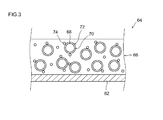
- FIG. 3 is a cross-sectional view schematically showing the structure of the positive electrode according to one embodiment of the present invention.
- FIG. 4 is a graph showing the viscosity ratio of the paste-like composition prepared in one test example.
- FIG. 5 is a graph showing the resistance ratio of the lithium ion secondary battery constructed in one test example.
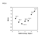
- FIG. 6 is a graph showing the relationship between the binder content and the resistance ratio.
- FIG. 7 is a graph showing the viscosity ratio of a paste-like composition prepared in another test example.
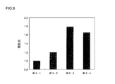
- FIG. 8 is a graph showing the resistance ratio of a lithium ion secondary battery constructed in another test example.
- FIG. 9 is a graph showing the relationship between the Y / X value and the resistance ratio of a lithium ion secondary battery constructed in another test example.
- FIG. 10 is a side view schematically showing a vehicle (automobile) provided with the lithium ion secondary battery according to the present invention.
- the lithium ion secondary battery provided by the present invention includes a positive electrode active material (coated positive electrode active material) whose surface is coated with a hydrophobic film as described above, and a positive electrode including a binder that is dissolved or dispersed in an aqueous solvent. It is characterized by having.
- a positive electrode active material coated positive electrode active material
- a positive electrode including a binder that is dissolved or dispersed in an aqueous solvent It is characterized by having.
- the manufacturing method of the lithium ion secondary battery disclosed here includes a coated positive electrode active material preparing step, a composition preparing step, and a composition applying step.
- the coated positive electrode active material preparation step includes preparing a coated positive electrode active material in which the surface of the positive electrode active material is coated with a hydrophobic film.
- the positive electrode active material used in the positive electrode of the lithium ion secondary battery disclosed herein is a material that can occlude and release lithium ions, and contains lithium and one or more transition metal elements
- a compound for example, lithium transition metal complex oxide
- lithium nickel composite oxide for example, LiNiO 2
- lithium cobalt composite oxide for example, LiCoO 2
- lithium manganese composite oxide for example, LiMn 2 O 4
- lithium nickel cobalt manganese composite oxide for example, LiNi 1).
- LiNi 1.1 lithium nickel composite oxide
- LiCoO 2 lithium manganese composite oxide
- LiMn 2 O 4 lithium nickel cobalt manganese composite oxide
- LiNi 1.1 / 3 Co 1/3 Mn 1/3 O 2 a ternary lithium-containing composite oxide.
- a polyanionic compound for example, LiFePO 4 whose general formula is represented by LiMPO 4, LiMVO 4, or Li 2 MSiO 4 (wherein M is at least one element of Co, Ni, Mn, and Fe), etc. 4 , LiMnPO 4 , LiFeVO 4 , LiMnVO 4 , Li 2 FeSiO 4 , Li 2 MnSiO 4 , Li 2 CoSiO 4 ) may be used as the positive electrode active material.
- Li 1 + x (Ni y Co z Mn 1-yz- ⁇ M ⁇ ) O 2 is preferable.
- the value of x in the above formula is 0 ⁇ x ⁇ 0.2
- the value of y is 0.5 ⁇ y ⁇ 1
- the value of z is 0 ⁇ z ⁇ 0.5
- ⁇ The value of 0 ⁇ ⁇ ⁇ 0.2 and 0.5 ⁇ y + z + ⁇ ⁇ 1.
- M include F, B, Al, W, Mo, Cr, Ta, Nb, V, Zr, Ti, and Y.
- M is one or more transition metal elements (that is, W, Mo, Cr which are Group 6 (chromium group) elements in the periodic table, or V, Nb which are Group 5 (vanadium group) elements. , Ta, or Ti, Zr, which is a Group 4 (titanium group) element, or Y, which is a Group 3 element.
- the present invention can be particularly preferably applied when using such a lithium nickel composite oxide having a high composition ratio of nickel (Ni). Nickel is sensitive to moisture and easily deteriorates.
- the surface of the positive electrode active material is coated with a hydrophobic coating, so that the positive electrode active material is contacted with an aqueous solvent (typically water). Can be prevented.
- aqueous solvent typically water
- the positive electrode active material disclosed herein can be, for example, secondary particles (granular powder formed by agglomerating many fine particles of the positive electrode active material) in a range of about 1 ⁇ m to 15 ⁇ m (for example, about 2 ⁇ m to 10 ⁇ m).
- the average particle diameter here means a median diameter (d50), and can be easily measured by a particle size distribution measuring apparatus based on various commercially available laser diffraction / scattering methods.
- Examples of the hydrophobic coating that covers the surface of the positive electrode active material disclosed herein include water-repellent resins and transition metal oxides.
- the water-repellent resin that covers the surface of the positive electrode active material will be described.
- a fluorine-based resin can be given.
- a polyvinylidene fluoride resin having a relatively high lithium ion permeability (conductivity) can be given.
- the polyvinylidene fluoride resin polyvinylidene fluoride (PVDF) obtained by polymerizing one kind of vinylidene fluoride monomer is preferably used.
- the polyvinylidene fluoride resin may be a copolymer of a vinyl monomer copolymerizable with vinylidene fluoride.
- vinyl monomers copolymerizable with vinylidene fluoride include hexafluoropropylene, tetrafluoroethylene, and ethylene trichloride fluoride. Further, a mixture of two or more of the above homopolymers and copolymers may be used.
- fluororesins include polytetrafluoroethylene (PTFE) and polyvinyl fluoride (PVF). Moreover, it can replace with fluorine resin and can also use resin materials, such as a polyacrylonitrile and a polyamideimide.
- a method of coating the surface of the positive electrode active material with a water repellent resin will be described.
- a paste-like mixture in which the positive electrode active material and the water-repellent resin are dispersed and mixed in an appropriate solvent is prepared, and dried at an appropriate temperature (for example, about 100 ° C. to 180 ° C.).
- a coated positive electrode active material whose surface is coated with a water-repellent resin can be obtained.
- the paste-like mixture can be kneaded using, for example, a planetary mixer.
- the solvent used in the paste-like mixture examples include organic solvents (organic solvents) such as N-methylpyrrolidone (NMP), pyrrolidone, methyl ethyl ketone, methyl isobutyl ketone, ixahexanone, toluene, dimethylformamide, dimethylacetamide, and the like. The combination of 2 or more types of these is mentioned.
- organic solvents such as N-methylpyrrolidone (NMP), pyrrolidone, methyl ethyl ketone, methyl isobutyl ketone, ixahexanone, toluene, dimethylformamide, dimethylacetamide, and the like.
- NMP N-methylpyrrolidone
- pyrrolidone pyrrolidone
- methyl ethyl ketone methyl isobutyl ketone
- ixahexanone ixahexanone
- toluene dimethyl
- the average particle diameter (median diameter: d50) of the positive electrode active material is C [ ⁇ m]
- the mass is D [g]
- the mass of the water-repellent resin covering the surface of the positive electrode active material is E [g. ]
- the relational expression 0.05 ⁇ C ⁇ (E / D) ⁇ 0.20 is satisfied. If it is less than 0.05, the surface of the positive electrode active material cannot be sufficiently coated, and contact with an aqueous solvent may not be suppressed. On the other hand, if it is larger than 0.20, the ion permeability of the water-repellent resin is too low, and the resistance may increase.
- transition metal oxide that covers the surface of the positive electrode active material
- tungsten oxide (WO 3 ) having tungsten as a constituent element, zirconium oxide (ZrO 2 ) having zirconium as a constituent element can be preferably used.
- the “mechanochemical treatment” means that the objects to be treated (here, the positive electrode active material and the transition metal oxide) are subjected to mechanical energy such as compressive force, shearing force, frictional force, etc. Is physically (mechanically) bonded (composite).
- An apparatus for performing the mechanochemical treatment is not particularly limited as long as mechanical energy such as shearing force is added to the positive electrode active material and the transition metal oxide.
- Examples thereof include a table ball mill, a planetary ball mill, a bead mill, a kneading and dispersing device, and a powder mixing device.
- the solvent is removed (for example, evaporated) from a mixed material obtained by kneading a solvent containing a metal alkoxide that can be dissolved in water or alcohol and the positive electrode active material, and this is heated appropriately.
- a coated positive electrode active material in which the surface of the positive electrode active material is coated with a transition metal oxide can be obtained.
- the metal alkoxide include tungsten ethoxide and zirconium butoxide.
- the specific surface area of the positive electrode active material based on the BET method is X [m 2 / g], and the mass A [mg] of the transition metal oxide as the coating material and the mass B [g of the positive electrode active material ],
- a / B is the oxide coating amount Y [mg / g]
- the value of Y / X is about 5 mg / m 2 to 50 mg / m 2 (preferably about 10 mg / m 2 to 40 mg / m 2 ) is preferable. If the value of Y / X is too smaller than 5 mg / m 2 , the surface of the positive electrode active material cannot be sufficiently covered, and contact with an aqueous solvent may not be suppressed.
- the value of Y / X is too larger than 50 mg / m 2 , the ion permeability of the water-repellent resin may be too low, and the resistance may increase.
- the value measured according to JIS K1477 shall be employ
- composition preparation step at least the coated positive electrode active material prepared in the above step and the binder-like positive electrode mixture layer obtained by kneading the aqueous solvent with the binder dissolved or dispersed in the aqueous solvent Preparation of a composition for forming (hereinafter sometimes simply referred to as “composition”) is included.
- the binder (binder) used for the positive electrode of the lithium ion secondary battery disclosed here is a binder that dissolves or disperses in an aqueous solvent because an aqueous solvent is used when the composition is prepared. If there is no particular limitation, it can be used.
- cellulose polymers such as carboxyl methyl cellulose (CMC), methyl cellulose (MC), cellulose acetate phthalate (CAP); polyvinyl alcohol (PVA); polyethylene oxide (PEO), polytetrafluoroethylene (PTFE), polyvinylidene fluoride ( PVDF) and the like; vinyl acetate copolymers; alkyltrimethylammonium salts and the like.
- amphiphilic compounds such as polyethylene oxide and alkyltrimethylammonium salts can be preferably used.
- polyethylene oxide having a mass average molecular weight of 500,000 or more can be preferably used.
- the affinity between the hydrophobic film (water repellent resin or transition metal oxide) of the coated positive electrode active material and the aqueous solvent (for example, water) is increased.
- the positive electrode active material and the binder (amphiphilic compound) are well dispersed.
- the said binder may be used individually by 1 type, and may be used in combination of 2 or more type.
- the added amount (content) of the binder is 100% by mass with respect to the total amount of the positive electrode mixture layer (nonvolatile content in the composition, that is, the total ratio of the coated positive electrode active material, the binder and the conductive material) described later.
- the composition application step includes applying the prepared composition to the positive electrode current collector.
- a conductive member made of a metal having good conductivity is preferably used, like the electrode current collector used for the positive electrode of a conventional lithium ion secondary battery.
- an aluminum material or an alloy material mainly composed of an aluminum material can be used.
- the shape of the positive electrode current collector may vary depending on the shape of the lithium ion secondary battery, and is not particularly limited, and may be various forms such as a rod shape, a plate shape, a sheet shape, a foil shape, and a mesh shape.
- a technique similar to a conventionally known method can be appropriately employed.
- the composition can be suitably applied to the surface of the positive electrode current collector by using an appropriate application device such as a gravure coater, comma coater, slit coater, or die coater. Thereafter, the composition applied to the positive electrode current collector is dried to remove the solvent, and is pressed (compressed) as necessary to form a positive electrode mixture layer. Thereby, the positive electrode (for example, sheet-like positive electrode) for lithium ion secondary batteries provided with a positive electrode electrical power collector and the positive electrode compound material layer formed on this positive electrode electrical power collector can be produced.
- an appropriate application device such as a gravure coater, comma coater, slit coater, or die coater.
- the composition applied to the positive electrode current collector is dried to remove the solvent, and is pressed (compressed) as necessary to form a positive electrode mixture layer.
- the positive electrode for example, sheet-like positive electrode
- the positive electrode compound material layer formed on this positive electrode electrical power collector can be produced.
- FIG. 3 is a cross-sectional view schematically showing the structure of the positive electrode 64 according to an embodiment of the present invention.
- a conductive material may be included in the positive electrode mixture layer 66 of the positive electrode 64, it is not shown in a simplified manner.
- the positive electrode 64 according to this embodiment includes a positive electrode current collector 62 and a positive electrode mixture layer 66 formed on the current collector 62.
- the positive electrode mixture layer 66 includes a coated positive electrode active material 72 in which the surface of the positive electrode active material 68 is coated with a hydrophobic film 70, and a binder 74.
- the positive electrode mixture layer 66 uses an aqueous solvent in the manufacturing process, but the positive electrode active material 68 is covered with the hydrophobic film 70, so that the positive electrode active material 68 and the aqueous solvent are in contact with each other. It is prevented. For this reason, although the obtained positive electrode 64 is produced using an aqueous solvent, alkali corrosion in the positive electrode current collector 62 is prevented. Further, when an amphiphilic compound (for example, polyethylene oxide) is used as the binder 74, a good dispersion arrangement of the coated positive electrode active material 72 can be realized in the positive electrode mixture layer 66 as shown in FIG.
- an amphiphilic compound for example, polyethylene oxide
- the negative electrode for a lithium ion secondary battery which becomes the other electrode, can be produced by the same technique as in the past.
- the negative electrode active material one kind or two or more kinds of materials conventionally used for lithium ion secondary batteries can be used without any particular limitation.
- a particulate carbon material (carbon particles) including a graphite structure (layered structure) at least partially is mentioned. Any carbon material of a so-called graphitic material (graphite), a non-graphitizable carbonaceous material (hard carbon), an easily graphitizable carbonaceous material (soft carbon), or a combination of these materials is preferred.
- graphite particles such as natural graphite can be preferably used.
- Such a negative electrode active material is typically dispersed in a suitable solvent (typically water) together with a binder (binder similar to the positive electrode mixture layer, for example, styrene butadiene rubber (SBR)).
- a paste-like composition for forming a negative electrode mixture layer can be prepared.
- An appropriate amount of this composition is applied onto a negative electrode current collector made of a copper material, a nickel material, or an alloy material mainly composed thereof, and further dried to form a negative electrode mixture layer.
- the negative electrode for lithium ion secondary batteries provided with a negative electrode collector and the negative electrode compound material layer formed on this negative electrode collector can be produced.
- a process of constructing a lithium ion secondary battery by housing the sheet-like positive electrode manufactured by applying the above-described method and the produced sheet-like negative electrode together with an electrolyte in a battery case will be described.
- the positive electrode and the negative electrode are laminated together with a total of two separator sheets and wound to produce a wound electrode body.
- the wound electrode body is accommodated in a battery case (for example, a flat rectangular parallelepiped case), and an electrolytic solution is injected into the battery case.
- a lithium ion secondary battery can be constructed
- the same non-aqueous electrolytic solution conventionally used for lithium ion secondary batteries can be used without any particular limitation.
- a nonaqueous electrolytic solution typically has a composition in which a supporting salt is contained in a suitable nonaqueous solvent.
- a suitable nonaqueous solvent 1 type, or 2 or more types selected from EC, PC, DMC, DEC, EMC etc. can be used, for example.
- the supporting salt for example, it can be used lithium salts such as LiPF 6, LiBF 4.
- the separator sheet include those made of a porous polyolefin resin or the like.
- the present invention is not intended to be limited to such an embodiment. That is, as long as a positive electrode having a positive electrode mixture layer including at least a coated positive electrode active material whose surface is coated with a hydrophobic coating and a binder that is dissolved or dispersed in an aqueous solvent, the positive electrode active material is constructed.
- the shape (outer shape and size) of the lithium ion secondary battery There is no particular limitation on the shape (outer shape and size) of the lithium ion secondary battery.
- a lithium ion secondary battery having a configuration in which a wound electrode body and an electrolytic solution are housed in a rectangular battery case will be described as an example.
- FIG. 1 is a perspective view schematically showing a lithium ion secondary battery 10 according to the present embodiment.
- FIG. 2 is a longitudinal sectional view taken along line II-II in FIG.
- the lithium ion secondary battery 10 according to this embodiment includes a battery case 15 made of metal (a resin or a laminate film is also suitable).
- the case (outer container) 15 includes a flat cuboid case main body 30 having an open upper end, and a lid body 25 that closes the opening 20.
- the lid body 25 seals the opening 20 of the case main body 30 by welding or the like.
- the lid 25 is provided with a safety valve 40 for discharging the gas generated inside the case 15 to the outside of the case 15 when the battery is abnormal, as in the case of the conventional lithium ion secondary battery. .
- the positive electrode 64 and the negative electrode 84 are laminated together with a total of two separator sheets 95 and wound, and then the flat shape produced by crushing and ablating the obtained wound body from the side surface direction.
- the wound electrode body 50 and the electrolyte solution are accommodated.
- the positive electrode mixture layer non-formed portion of the positive electrode 64 that is, the portion where the positive electrode current collector 62 is exposed without forming the positive electrode mixture layer 66
- the positive electrode 64 and the negative electrode 84 are formed so that the negative electrode mixture layer non-formed portion (that is, the portion where the negative electrode collector layer 90 is not formed and the negative electrode collector 82 is exposed) protrudes from both sides in the width direction of the separator sheet 95. Are overlapped with a slight shift in the width direction.
- the electrode mixture layer non-formed portions of the positive electrode 64 and the negative electrode 84 are respectively wound core portions (that is, the positive electrode mixture layer forming portion and the negative electrode 84 of the positive electrode 64.
- the portion where the negative electrode mixture layer forming portion and the two separator sheets 95 are closely wound) protrudes outward.
- the positive electrode terminal 60 is joined to the protruding portion on the positive electrode side, and the positive electrode 64 and the positive electrode terminal 60 of the wound electrode body 50 formed in the flat shape are electrically connected.
- the negative electrode terminal 80 is joined to the protruding portion on the negative electrode side, and the negative electrode 84 and the negative electrode terminal 80 are electrically connected.
- the positive and negative electrode terminals 60 and 80 and the positive and negative electrode current collectors 62 and 82 can be joined by, for example, ultrasonic welding, resistance welding, or the like.
- Example 1 ⁇ Performance Evaluation of Pasty Composition> ⁇ Example 1-1> Li 1.05 Ni 0.75 Co 0.1 Mn 0.1 Al 0.05 O 2 (hereinafter abbreviated as LNO) as a positive electrode active material and a hydrophobic coating (water repellent resin) 2 parts by mass of polyvinylidene fluoride (PVDF) was added to NMP and kneaded by a planetary mixer to prepare a paste-like mixture (solid content concentration of about 10% by mass). The pasty mixture was dried at 120 ° C. for 10 hours in a reduced pressure atmosphere.
- LNO Li 1.05 Ni 0.75 Co 0.1 Mn 0.1 Al 0.05 O 2
- PVDF polyvinylidene fluoride
- the dried aggregate was lightly pulverized in a mortar to prepare a positive electrode active material (coated positive electrode active material) with a PVDF coating in which the surface of LNO was coated with PVDF (hydrophobic coating).
- the mass ratio of the produced positive electrode active material with a PVDF coating, acetylene black (AB) as a conductive material, and polyethylene oxide powder (mass average molecular weight: 500,000) as a binder is 92: 5: 3.
- these materials were dispersed in ion-exchanged water to prepare a paste-like composition for forming a positive electrode mixture layer according to Example 1-1.
- Example 1-2> A paste-like composition for forming a positive electrode mixture layer according to Example 1-2 was prepared in the same manner as Example 1-1 except that PVDF was used as the binder.
- a paste-like composition for forming a positive electrode mixture layer according to Example 1-3 was prepared.
- Example 1-4> A paste-like composition for forming a positive electrode mixture layer according to Example 1-4 was prepared in the same manner as Example 1-3 except that PVDF was used as the binder.
- composition viscosity ratio of the compositions was measured using a B-type viscometer. That is, at room temperature (typically about 25 ° C.), the viscosity (initial viscosity) after the preparation of the composition according to each example was measured at a rotation speed of 20 rpm, and left at room temperature for 24 hours. The viscosity after 24 hours of the composition (viscosity after 24 hours) was measured. At this time, the ratio of the viscosity after 24 hours to the initial viscosity (viscosity after 24 hours / initial viscosity) was defined as the viscosity ratio. The measurement results are shown in FIG.
- the composition in which the surface of the positive electrode active material (LNO) is covered with a hydrophobic coating (water repellent resin) has a smaller change in viscosity than the composition not covered.
- a hydrophobic coating water repellent resin
- the composition using amphiphilic polyethylene oxide as the binder as in Example 1-1 was a stable composition with almost no change in viscosity.
- the composition according to Example 1-3 has a reduced viscosity because the binder (PEO) is decomposed under strong alkali, and the composition according to Example 1-4 has a binder (PVDF) under strong alkali. ) Is gelled, it is considered that the viscosity is increased.
- ⁇ Performance evaluation of lithium ion secondary battery> After applying the paste-like composition for forming a positive electrode mixture layer according to Example 1-1 on a positive electrode current collector (aluminum foil) having a thickness of about 15 ⁇ m at a coating amount of 6 mg / cm 2 per side, and drying, A positive electrode sheet according to Example 1-1 in which a positive electrode mixture layer was formed on the positive electrode current collector was produced by a roll press treatment. On the other hand, weighing is performed so that the mass ratio of flaky graphite as the negative electrode active material, styrene butadiene rubber (SBR) as the binder, and carboxymethyl cellulose (CMC) as the thickener is 98: 1: 1.
- SBR styrene butadiene rubber
- CMC carboxymethyl cellulose
- a paste-like composition for forming a negative electrode mixture layer was prepared.
- the composition was applied onto a negative electrode current collector (copper foil) having a thickness of about 10 ⁇ m at a coating amount of 4 mg / cm 2 per side and dried, and then treated by a roll press to form a coating on the negative electrode current collector.
- a negative electrode sheet according to Example 1-1 on which a negative electrode mixture layer was formed was produced.
- the positive electrode mixture layer of the positive electrode sheet was punched out to 3 cm ⁇ 4 cm to produce a positive electrode.
- the negative electrode mixture layer of the negative electrode sheet was punched out to 3 cm ⁇ 4 cm to produce a negative electrode.
- the lithium ion secondary battery according to Example 1-1 was constructed by housing in a film.
- a solution in which 1 mol / L LiPF 6 was dissolved in a mixed solvent of ethylene carbonate (EC), ethyl methyl carbonate (EMC), and dimethyl carbonate (DMC) in a volume ratio of 4: 3: 3 was used.
- a battery was constructed in the same manner as the lithium ion secondary battery according to Example 1-1 using the compositions according to Examples 1-2 to 1-4.
- ⁇ Resistance measurement test> the initial resistance of the lithium ion secondary battery according to Example 1-1 constructed above was measured. That is, after adjusting to a SOC 60% charge state, a constant current discharge is performed at ⁇ 15 ° C. for 10 seconds under a temperature of ⁇ 15 ° C., and a linear approximation line of the plot value of current (I) ⁇ voltage (V) at this time The initial resistance was determined from the slope of. Next, for the lithium ion secondary battery according to Example 1-1 after the initial resistance measurement, charging and discharging were repeated 1000 cycles, and the resistance after 1000 cycles was measured.
- the charge / discharge conditions for one cycle were as follows: the temperature was 25 ° C., and the charge was performed by the CC / CV method up to an upper limit voltage of 4.1V at 2C, and then the CC discharge was performed at 2C to the lower limit voltage of 3.0V.
- the resistance after 1000 cycles was calculated
- the ratio of the resistance after 1000 cycles to the initial resistance was defined as the resistance ratio.
- the resistance ratio of the lithium ion secondary batteries according to Examples 1-2 to 1-4 was measured. The measurement results are shown in FIG.
- the lithium ion secondary battery including the positive electrode active material covered with the hydrophobic film (water repellent resin) is compared with the lithium ion secondary battery including the positive electrode active material not covered. It was confirmed that the resistance change after 1000 cycles (that is, the increase in resistance) was small.
- a lithium ion secondary battery using amphiphilic polyethylene oxide as a binder is excellent in cycle characteristics with little resistance change even after 1000 cycles of charge and discharge. It was confirmed to be a secondary battery.
- lithium ion secondary batteries according to Examples 2-2 to 2-7 were constructed in the same manner as the battery according to Example 2-1 above.
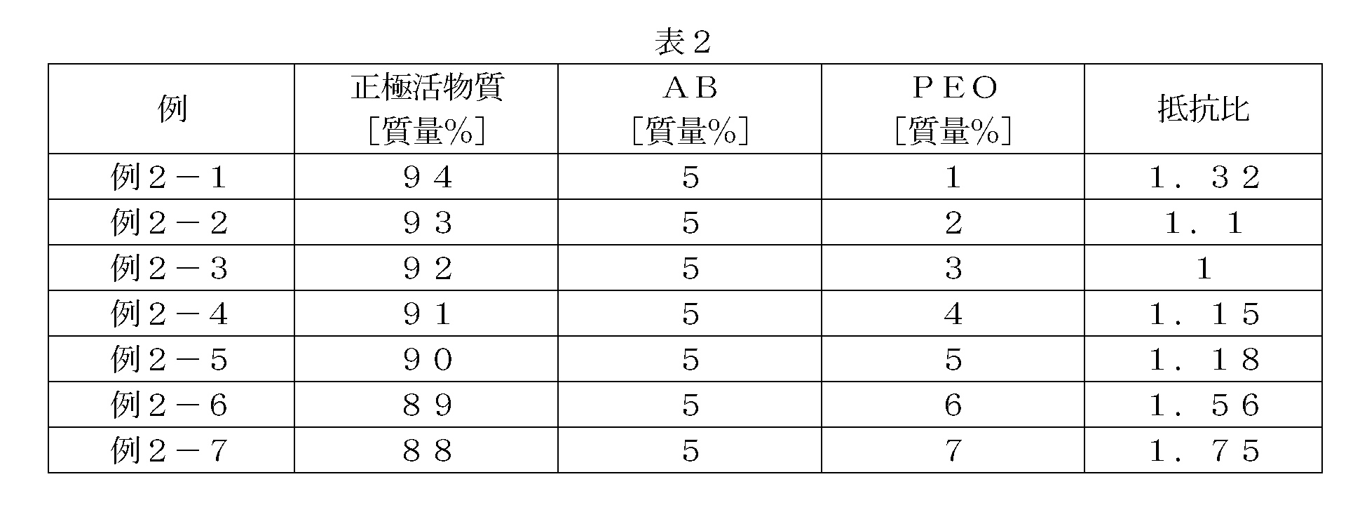
- Table 2 shows the mass ratio of the positive electrode active material with PVDF coating (coated positive electrode active material), AB, and polyethylene oxide (PEO) in each example.
- PVDF coating coated positive electrode active material
- AB coated positive electrode active material
- PEO polyethylene oxide
- the resistance ratio increased for the lithium ion secondary battery having a binder content of 1 mass%.
- the resistance ratio is suppressed to 1.2 or less.
- the resistance ratio hardly changed, and it was confirmed that the cycle characteristics were preferably improved.
- Example 3-1 100 parts by mass of LNO as a positive electrode active material and 3 parts by mass of tungsten oxide nanopowder (WO 3 ) as a hydrophobic coating (transition metal oxide) were put into a table ball mill machine, and mechanochemical treatment (500 rpm, 1 hour) surface of LNO was prepared coated WO 3 with the positive electrode active material (cathode active material coated) with WO 3 by.
- the BET specific surface area of the positive electrode active material (LNO) measured in accordance with JIS K1477 (JIS Z 8830) was 0.5 m 2 / g.
- Example 3-1 A paste-like composition for forming a positive electrode mixture layer according to Example 3-1 was prepared.
- Example 3 was prepared by weighing LNO as a positive electrode active material, AB as a conductive material, and PEO as a binder so as to have a mass ratio of 92: 5: 3, and dispersing these materials in ion-exchanged water.
- a paste-like composition for forming a positive electrode mixture layer according to -3 was prepared.
- a paste-like composition for forming a positive electrode mixture layer according to Example 3-4 was prepared in the same manner as Example 3-3, except that PVDF was used as the binder.
- composition viscosity measurement test> For the compositions according to Examples 3-1 to 3-4 prepared above, the viscosity ratio was measured under the same conditions as the viscosity measurement tests performed on the compositions of Examples 1-1 to 1-4. did. The measurement results are shown in FIG.
- the composition in which the surface of the positive electrode active material (LNO) is covered with a hydrophobic coating (transition metal oxide) has a smaller viscosity change than the composition not covered. I was able to confirm.
- a composition using amphiphilic polyethylene oxide as a binder was confirmed to be a stable composition with almost no change in viscosity.
- a lithium ion secondary battery according to Example 3-1 was constructed in the same manner as in Example 1-1 except that the composition according to Example 3-1 was used.
- a battery was constructed using the compositions according to Examples 3-2 to 3-4 in the same manner as the lithium ion secondary battery according to 3-1 above.
- a lithium ion secondary battery including a positive electrode active material covered with a hydrophobic film is a lithium ion secondary battery including a positive electrode active material that is not covered;
- the resistance change after 1000 cycles that is, the increase in resistance
- a lithium ion secondary battery using amphiphilic polyethylene oxide as a binder has excellent cycle characteristics that hardly change in resistance after 1000 cycles of charge and discharge. It was confirmed to be a secondary battery.
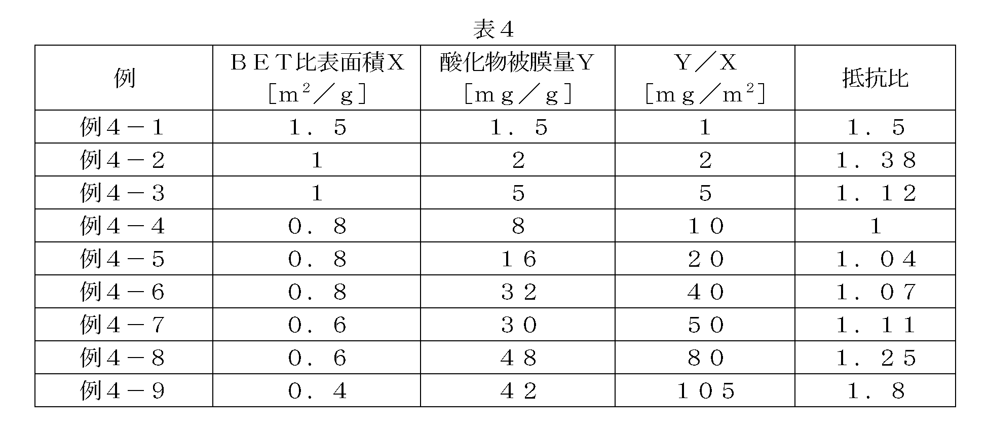
- Example 4-1 LNO 100 g having a BET specific surface area X measured in accordance with JIS K1477 (JIS Z 8830) of 1.5 m 2 / g and WO 3 150 mg were put into a table-top ball mill machine and subjected to mechanochemical treatment (500 rpm, 1 hour). surface of LNO was prepared coated WO 3 with the positive electrode active material (cathode active material coated) with WO 3.
- a / B which is the ratio between the mass A [mg] of WO 3 and the mass B [g] of LNO, is defined as Y / mg oxide coating amount (WO 3 coating amount)
- Y [mg / g] X was 1 mg / m 2 .
- the above prepared positive electrode active material with WO 3 , AB and PEO are weighed so that the mass ratio is 92: 5: 3, and these materials are dispersed in ion-exchanged water to obtain a paste form according to Example 4-1.
- a positive electrode mixture layer forming composition was prepared.
- a lithium ion secondary battery according to Example 4-1 was constructed in the same manner as Example 1-1 except that the composition according to Example 4-1 was used.
- Example 4-2 A lithium ion secondary battery according to Example 4-2 was obtained in the same manner as in Example 4-1, except that 100 g of LNO having a BET specific surface area X [m 2 / g] of 1 m 2 / g and 200 mg of WO 3 were used. It was constructed. At this time, Y / X was 2 mg / m 2 .
- Example 4-4 The lithium ion secondary according to Example 4-4 was used in the same manner as in Example 4-1, except that 100 g of LNO having a BET specific surface area X [m 2 / g] of 0.8 m 2 / g and 800 mg of WO 3 were used. A battery was built. At this time, Y / X was 10 mg / m 2 .
- Example 4-5 The lithium ion secondary according to Example 4-5 was obtained in the same manner as in Example 4-1, except that 100 g of LNO having a BET specific surface area X [m 2 / g] of 0.8 m 2 / g and WO 3 1600 mg were used. A battery was built. At this time, Y / X was 20 mg / m 2 .
- Example 4-6> The lithium ion secondary according to Example 4-6 was used in the same manner as in Example 4-1, except that 100 g of LNO having a BET specific surface area X [m 2 / g] of 0.8 m 2 / g and 3200 mg of WO 3 were used. A battery was built.
- Example 4-7 The lithium ion secondary according to Example 4-7 was obtained in the same manner as in Example 4-1, except that 100 g of LNO having a BET specific surface area X [m 2 / g] of 0.6 m 2 / g and WO 3 of 3000 mg were used. A battery was built. At this time, Y / X was 50 mg / m 2 .
- Example 4-8 Lithium ion secondary according to Example 4-8 in the same manner as in Example 4-1, except that 100 g of LNO having a BET specific surface area X [m 2 / g] of 0.6 m 2 / g and 4800 mg of WO 3 were used. A battery was built. At this time, Y / X was 80 mg / m 2 .
- the lithium ion secondary battery 10 can be used as a lithium ion secondary battery for various applications because it can realize reduction of environmental load in the manufacturing process and has excellent cycle characteristics. It is. For example, as shown in FIG. 10, it can be suitably used as a power source for a vehicle driving motor (electric motor) mounted on a vehicle 100 such as an automobile.
- vehicle 100 such as an automobile.
- the type of vehicle 100 is not particularly limited, but is typically a hybrid vehicle, an electric vehicle, a fuel cell vehicle, or the like.
- Such lithium ion secondary battery 10 may be used alone, or may be used in the form of an assembled battery that is connected in series and / or in parallel.
Landscapes
- Chemical & Material Sciences (AREA)
- Chemical Kinetics & Catalysis (AREA)
- Electrochemistry (AREA)
- General Chemical & Material Sciences (AREA)
- Engineering & Computer Science (AREA)
- Materials Engineering (AREA)
- Inorganic Chemistry (AREA)
- Manufacturing & Machinery (AREA)
- Battery Electrode And Active Subsutance (AREA)
Abstract
Description
一方、水系溶媒を用いる場合の利点としては、有機溶媒(例えばN-メチルピロリドン)を用いた場合と比較して、有機溶媒およびそれに伴う産業廃棄物が少なくて済み、そのための設備及び処理コストが発生しないことから総じて環境負荷が低減され得る。このような利点を考慮すれば、環境負荷の低い水系溶媒(典型的には水)を使用するとともに、該水系溶媒を使用した場合であっても所望する電池性能を実現できる性状の正極合材層(ひいては正極)を形成し得る技術が求められる。
(但し、0≦x≦0.2、0.5≦y≦1、0≦z≦0.5、0≦γ≦0.2、0.5≦y+z+γ≦1、MはF、B、Al、W、Mo、Cr、Ta、Nb、V、Zr、Ti、Yからなる群から選ばれる少なくとも一種の元素である。)
で示されるリチウムニッケル複合酸化物を用いる。
このようなニッケル(Ni)の組成比が高いリチウムニッケル複合酸化物を主成分とする正極活物質は、リチウムイオン二次電池の正極活物質として好ましい種々の特性を有する一方、ニッケルは水分に対する感度が高く劣化しやすい性質を有するため、本発明の構成を採用することによる効果が特に発揮され得る。
かかるリチウムイオン二次電池では、正極活物質の表面が疎水性被膜により被覆されているため正極活物質と水分との接触を抑制することができ、その製造工程において水系溶媒と接触することが防止されている。すなわち、結着材の分解やゲル化、活物質の凝集、正極集電体の腐食等が防止されると共に環境負荷が低減された高性能なリチウムイオン二次電池となっている。
好適な他の一態様では、上記正極合材層(の全量)を100質量%としたとき、該正極合材層に含まれる上記結着材は、2質量%~5質量%である。また、好適な他の一態様では、上記疎水性被膜は、撥水性樹脂から形成されている。好ましくは、上記撥水性樹脂は、フッ素系樹脂である。また、好適な他の一態様では、上記疎水性被膜は、遷移金属酸化物から形成されている。好ましくは、上記遷移金属酸化物は、酸化タングステン又は酸化ジルコニウムである。
また、好適な他の一態様では、上記正極活物質は、その表面が上記遷移金属酸化物からなる疎水性被膜により被覆されており、上記正極活物質のBET法に基づく比表面積をX[m2/g]とし、上記被覆物質である遷移金属酸化物の質量A[mg]と上記正極活物質の質量B[g]との比であるA/Bを酸化物被膜量Y[mg/g]としたときのY/Xの値が5mg/m2~50mg/m2である。また、好適な他の一態様では、上記正極活物質は、一般式:
Li1+x(NiyCozMn1-y-z-γMγ)O2
(但し、0≦x≦0.2、0.5≦y≦1、0≦z≦0.5、0≦γ≦0.2、0.5≦y+z+γ≦1、MはF、B、Al、W、Mo、Cr、Ta、Nb、V、Zr、Ti、Yからなる群から選ばれる少なくとも一種の元素である。)
で示されるリチウムニッケル複合酸化物である。
以下、ここで開示されるリチウムイオン二次電池の製造方法と該製法によって製造されるリチウムイオン二次電池について詳細に説明する。
まず、被覆正極活物質準備工程ついて説明する。被覆正極活物質準備工程には、正極活物質の表面が疎水性被膜によって被覆された被覆正極活物質を用意することが含まれている。
また、一般式がLiMPO4或いはLiMVO4或いはLi2MSiO4(式中のMはCo、Ni、Mn、Feのうちの少なくとも一種以上の元素)等で表記されるようなポリアニオン系化合物(例えばLiFePO4、LiMnPO4、LiFeVO4、LiMnVO4、Li2FeSiO4、Li2MnSiO4、Li2CoSiO4)を上記正極活物質として用いてもよい。
ここで開示される正極活物質は、例えば凡そ1μm~15μm(例えば凡そ2μm~10μm)の範囲内にある二次粒子(正極活物質の微粒子が多数凝集して形成された粒状粉末)であり得る。なお、ここでの平均粒径はメジアン径(d50)をいい、市販されている種々のレーザー回折・散乱法に基づく粒度分布測定装置によって容易に測定することができる。
まず、正極活物質の表面を被覆する撥水性樹脂について説明する。ここで開示される撥水性樹脂を構成する材料としては、例えばフッ素系樹脂が挙げられる。中でもリチウムイオンの透過性(伝導性)が比較的高いポリフッ化ビニリデン系樹脂が挙げられる。ポリフッ化ビニリデン系樹脂としては、フッ化ビニリデンのモノマーを1種類で重合したポリフッ化ビニリデン(PVDF)が好ましく用いられる。また、ポリフッ化ビニリデン系樹脂は、フッ化ビニリデンと共重合可能なビニル系単量体との共重合体であってもよい。フッ化ビニリデンと共重合可能なビニル系単量体としては、ヘキサフルオロプロピレン、テトラフルオロエチレンおよび三塩化フッ化エチレン等が例示される。さらに、上記単独重合体及び共重合体の2種類以上を混合したものであってもよい。その他のフッ素系樹脂としては、ポリテトラフルオロエチレン(PTFE)、ポリフッ化ビニル(PVF)等が挙げられる。また、フッ素系樹脂に代えて、ポリアクリロニトリル、ポリアミドイミド等の樹脂材料を用いることもできる。
また、他の方法として、例えば、水若しくはアルコールに溶解可能な金属アルコキシドを含む溶媒と上記正極活物質を混練して得た混合材料から溶媒を除去(例えば蒸発)させて、これを適当な加熱条件(例えば200℃~700℃)で加熱することによって、正極活物質の表面が遷移金属酸化物で被覆された被覆正極活物質を得ることができる。上記金属アルコキシドとしては、例えば、タングステンエトキシド、ジルコニウムブトキシド等が挙げられる。
ここで開示されるリチウムイオン二次電池の正極に用いられる結着材(バインダ)としては、上記組成物を調製する際に水系溶媒を使用するため、水系溶媒に溶解または分散する結着材であれば特に制限なく使用することができる。例えば、カルボキシルメチルセルロース(CMC)、メチルセルロース(MC)、酢酸フタル酸セルロース(CAP)等のセルロース系ポリマー;ポリビニルアルコール(PVA);ポリエチレンオキシド(PEO)、ポリテトラフルオロエチレン(PTFE)、ポリフッ化ビニリデン(PVDF)等のフッ素系樹脂;酢酸ビニル共重合体;アルキルトリメチルアンモニウム塩等が挙げられる。特に、ポリエチレンオキシドやアルキルトリメチルアンモニウム塩等のような両親媒性の化合物を好ましく用いることができる。さらに、質量平均分子量が50万以上のポリエチレンオキシドを好ましく用いることができる。結着材として上記の両親媒性の化合物を用いると、被覆正極活物質の疎水性被膜(撥水性樹脂或いは遷移金属酸化物)と水系溶媒(例えば水)との親和性が高まるため、組成物において上記正極活物質及び結着材(両親媒性の化合物)が良好に分散する。なお、上記結着材を一種のみ単独で用いてもよいし、二種以上を組み合わせて用いてもよい。
結着材の添加量(含有量)は、後述する正極合材層(組成物中の不揮発分、即ち被覆正極活物質、結着材及び導電材等の合計割合)の全量を100質量%としたときに凡そ2質量%~5質量%(例えば凡そ2質量%~3質量%)の範囲内であることが好ましい。結着材の添加量を上記範囲内となるように調整することでサイクル特性に優れた(抵抗増加の小さい)リチウムイオン二次電池となり得る。
上記正極集電体としては、従来のリチウムイオン二次電池の正極に用いられている電極集電体と同様、導電性の良好な金属からなる導電性部材が好ましく用いられる。例えば、アルミニウム材又はアルミニウム材を主体とする合金材を用いることができる。正極集電体の形状は、リチウムイオン二次電池の形状等に応じて異なり得るため、特に制限はなく、棒状、板状、シート状、箔状、メッシュ状等の種々の形態であり得る。
上記組成物を塗布する方法としては、従来公知の方法と同様の技法を適宜採用することができる。例えば、グラビアコーター、コンマコーター、スリットコーター、ダイコーター等の適当な塗布装置を使用することにより、正極集電体の表面に組成物を好適に塗布することができる。
その後、正極集電体に塗布された組成物を乾燥させて溶媒を除去し、必要に応じてプレス(圧縮)することによって正極合材層を形成する。これにより、正極集電体と該正極集電体上に形成された正極合材層とを備えるリチウムイオン二次電池用の正極(例えばシート状の正極)を作製することができる。
なお、以下の図面において、同じ作用を奏する部材・部位には同じ符号を付し、重複する説明は省略することがある。また、各図における寸法関係(長さ、幅、厚さ等)は、必ずしも実際の寸法関係を反映するものではない。
図1に示すように、本実施形態に係るリチウムイオン二次電池10は、金属製(樹脂製又はラミネートフィルム製も好適である。)の電池ケース15を備える。このケース(外容器)15は、上端が開放された扁平な直方体状のケース本体30と、その開口部20を塞ぐ蓋体25とを備える。溶接等により蓋体25は、ケース本体30の開口部20を封止している。ケース15の上面(すなわち蓋体25)には、捲回電極体50の正極(シート状の正極)64と電気的に接続する正極端子60および該電極体の負極(シート状の負極)84と電気的に接続する負極端子80が設けられている。また、蓋体25には、従来のリチウムイオン二次電池のケースと同様に、電池異常の際にケース15内部で発生したガスをケース15の外部に排出するための安全弁40が設けられている。ケース15の内部には、正極64および負極84を計二枚のセパレータシート95とともに積層して捲回し、次いで得られた捲回体を側面方向から押しつぶして拉げさせることによって作製される扁平形状の捲回電極体50及び上記電解液が収容されている。
[試験例1]
<ペースト状組成物の性能評価>
<例1-1>
正極活物質としてのLi1.05Ni0.75Co0.1Mn0.1Al0.05O2(以下、LNOと省略する。)100質量部と、疎水性被膜(撥水性樹脂)としてのポリフッ化ビニリデン(PVDF)2質量部とを、NMPに添加してプラネタリーミキサーにて混練することによりペースト状の混合物(固形分濃度約10質量%)を調製した。そして該ペースト状の混合物を減圧雰囲気下において120℃で10時間乾燥した。乾燥後、乾燥凝集物を乳鉢で軽く粉砕することにより、LNOの表面がPVDF(疎水性被膜)によって被覆されたPVDF被膜付き正極活物質(被覆正極活物質)を作製した。
上記作製したPVDF被膜付き正極活物質と、導電材としてのアセチレンブラック(AB)と、結着材としてのポリエチレンオキシド粉末(質量平均分子量:50万)との質量比が92:5:3となるように秤量し、これら材料をイオン交換水に分散させて例1-1に係るペースト状の正極合材層形成用組成物を調製した。
結着材としてPVDFを用いた他は例1-1と同様にして、例1-2に係るペースト状の正極合材層形成用組成物を調製した。
<例1-3>
正極活物質としてのLNOと、導電材としてのABと、結着材としてのポリエチレンオキシド(PEO)との質量比が92:5:3となるように秤量し、これら材料をイオン交換水に分散させて例1-3に係るペースト状の正極合材層形成用組成物を調製した。
<例1-4>
結着材としてPVDFを用いた他は例1-3と同様にして、例1-4に係るペースト状の正極合材層形成用組成物を調製した。
例1-1から例1-4に係る組成物に対して、B型粘度計を用いて組成物の粘度比を測定した。即ち、常温(典型的には25℃程度)において、回転数20rpmで各例に係る組成物の調製後の粘度(初期粘度)を測定し、24時間常温中で放置した後、各例に係る組成物の24時間経過後の粘度(24時間後粘度)を測定した。このとき初期粘度に対する24時間後粘度の比(24時間後粘度/初期粘度)を、粘度比とした。測定結果を図4及び表1に示す。

上記例1-1に係るペースト状の正極合材層形成用組成物を厚さ15μm程度の正極集電体(アルミニウム箔)上に片面当たり塗布量6mg/cm2で塗布して乾燥した後、ロールプレスによる処理を行って、該正極集電体上に正極合材層が形成された例1-1に係る正極シートを作製した。
一方、負極活物質としての鱗片状グラファイトと、結着材としてのスチレンブタジエンラバー(SBR)と、増粘材としてのカルボキシメチルセルロース(CMC)との質量比が98:1:1となるように秤量し、これら材料をイオン交換水に分散させてペースト状の負極合材層形成用組成物を調製した。該組成物を厚さ10μm程度の負極集電体(銅箔)上に片面当たり塗布量4mg/cm2で塗布して乾燥した後、ロールプレスによる処理を行って、該負極集電体上に負極合材層が形成された例1-1に係る負極シートを作製した。
次いで、正極シートの正極合材層を3cm×4cmに打ち抜いて、正極を作製した。また、負極シートの負極合材層を3cm×4cmに打ち抜いて、負極を作製した。正極にアルミリードを取り付け、負極にニッケルリードを取り付け、これらをセパレータシート(ポリプロピレン/ポリエチレン/ポリプロピレン複合体多孔質膜)を挟んで対向配置させ(積層させ)、電解液と共にラミネート型のケース(ラミネートフィルム)に収容することにより例1-1に係るリチウムイオン二次電池を構築した。電解液としては、エチレンカーボネート(EC)とエチルメチルカーボネート(EMC)とジメチルカーボネート(DMC)との体積比4:3:3の混合溶媒に1mol/LのLiPF6を溶解させたものを使用した。また、例1-2から例1-4に係る組成物を用いて、上記例1-1に係るリチウムイオン二次電池と同様にして電池を構築した。
まず、上記構築した例1-1に係るリチウムイオン二次電池について、初期抵抗を測定した。即ち、SOC60%の充電状態に調整した後、-15℃の温度条件下、10Cで10秒間の定電流放電を行い、このときの電流(I)‐電圧(V)のプロット値の一次近似直線の傾きから初期抵抗を求めた。
次いで、上記初期抵抗測定後の例1-1に係るリチウムイオン二次電池について、充放電を1000サイクル繰り返し、1000サイクル後の抵抗を測定した。1サイクルの充放電条件は、25℃の温度条件下、2Cで上限電圧4.1VまでCC/CV方式で充電を行い、その後2Cで下限電圧3.0VまでCC放電を行った。1000サイクル後のリチウムイオン二次電池について、上記初期抵抗を測定したときと同様の手法により1000サイクル後の抵抗を求めた。このとき、初期抵抗に対する1000サイクル後の抵抗の比(1000サイクル後の抵抗/初期抵抗)を、抵抗比とした。同様にして、例1-2から例1-4に係るリチウムイオン二次電池について抵抗比を測定した。測定結果を図5及び表1に示す。
上記例1-1のリチウムイオン二次電池では、正極合材層中の結着材の含有量が3質量%であったが、該結着材の含有量によってリチウムイオン二次電池の抵抗比がどのように変化するのかを測定した。ここでは、例2-1から例2-7の7種類のリチウムイオン二次電池を用意した。
例1-1に係るPVDF被膜付き正極活物質と、ABと、ポリエチレンオキシド(PEO)との質量比が94:5:1であるペースト状の正極合材層形成用組成物を用いた他は例1-1と同様にして、例2-1に係るリチウムイオン二次電池を構築した。また、例2-2から例2-7に係るリチウムイオン二次電池を上記例2-1に係る電池と同様にして構築した。このときの各例におけるPVDF被膜付き正極活物質(被覆正極活物質)と、ABと、ポリエチレンオキシド(PEO)との質量比を表2に示す。
上記構築した例2-1から例2-7に係るリチウムイオン二次電池について、上記例1-1から例1-4の各二次電池に対して行った抵抗測定試験と同一の条件下で抵抗比を測定した。測定結果を図6及び表2に示す。
<ペースト状組成物の性能評価>
<例3-1>
正極活物質としてのLNO100質量部と、疎水性被膜(遷移金属酸化物)としての酸化タングステンナノパウダー(WO3)3質量部とを卓上ボールミル機に投入し、メカノケミカル処理(500rmp、1時間)によりLNOの表面がWO3で被覆されたWO3付き正極活物質(被覆正極活物質)を作製した。ここで、JIS K1477(JIS Z 8830)に準拠して測定した上記正極活物質(LNO)のBET比表面積は0.5m2/gであった。
上記作製したWO3付き正極活物質と、導電材としてのABと、結着材としてのPEOとの質量比が92:5:3となるように秤量し、これら材料をイオン交換水に分散させて例3-1に係るペースト状の正極合材層形成用組成物を調製した。
<例3-2>
結着材としてPVDFを用いた他は例3-1と同様にして、例3-2に係るペースト状の正極合材層形成用組成物を調製した。
<例3-3>
正極活物質としてのLNOと、導電材としてのABと、結着材としてのPEOとの質量比が92:5:3となるように秤量し、これら材料をイオン交換水に分散させて例3-3に係るペースト状の正極合材層形成用組成物を調製した。
<例3-4>
結着材としてPVDFを用いた他は例3-3と同様にして、例3-4に係るペースト状の正極合材層形成用組成物を調製した。
上記調製した例3-1から例3-4に係る組成物について、上記例1-1から例1-4の各組成物に対して行った粘度測定試験と同一の条件下で粘度比を測定した。測定結果を図7及び表3に示す。

上記例3-1に係る組成物を用いた他は上記例1-1と同様にして、例3-1に係るリチウムイオン二次電池を構築した。また、例3-2から例3-4に係る組成物を用いて、上記3-1に係るリチウムイオン二次電池と同様にして電池を構築した。
上記構築した例3-1から例3-4に係るリチウムイオン二次電池について、上記例1-1から例1-4の各二次電池に対して行った抵抗測定試験と同一の条件下で抵抗比を測定した。測定結果を図8及び表3に示す。
<例4-1>
JIS K1477(JIS Z 8830)に準拠して測定したBET比表面積Xが1.5m2/gのLNO100gと、WO3150mgとを卓上ボールミル機に投入しメカノケミカル処理(500rpm、1時間)によって、LNOの表面がWO3で被覆されたWO3付き正極活物質(被覆正極活物質)を作製した。ここで、WO3の質量A[mg]とLNOの質量B[g]との比であるA/Bを酸化物被膜量(WO3被膜量)Y[mg/g]とした場合、Y/Xは1mg/m2であった。
上記作製したWO3付き正極活物質と、ABと、PEOとの質量比が92:5:3となるように秤量し、これら材料をイオン交換水に分散させて例4-1に係るペースト状の正極合材層形成用組成物を調製した。該例4-1に係る組成物を用いた他は上記例1-1と同様にして、例4-1に係るリチウムイオン二次電池を構築した。
<例4-2>
BET比表面積X[m2/g]が1m2/gのLNO100gと、WO3200mgとを用いた他は上記例4-1と同様にして、例4-2に係るリチウムイオン二次電池を構築した。このとき、Y/Xは2mg/m2であった。
<例4-3>
BET比表面積X[m2/g]が1m2/gのLNO100gと、WO3500mgとを用いた他は上記例4-1と同様にして、例4-3に係るリチウムイオン二次電池を構築した。このとき、Y/Xは5mg/m2であった。
<例4-4>
BET比表面積X[m2/g]が0.8m2/gのLNO100gと、WO3800mgとを用いた他は上記例4-1と同様にして、例4-4に係るリチウムイオン二次電池を構築した。このとき、Y/Xは10mg/m2であった。
<例4-5>
BET比表面積X[m2/g]が0.8m2/gのLNO100gと、WO31600mgとを用いた他は上記例4-1と同様にして、例4-5に係るリチウムイオン二次電池を構築した。このとき、Y/Xは20mg/m2であった。
<例4-6>
BET比表面積X[m2/g]が0.8m2/gのLNO100gと、WO33200mgとを用いた他は上記例4-1と同様にして、例4-6に係るリチウムイオン二次電池を構築した。このとき、Y/Xは40mg/m2であった。
<例4-7>
BET比表面積X[m2/g]が0.6m2/gのLNO100gと、WO33000mgとを用いた他は上記例4-1と同様にして、例4-7に係るリチウムイオン二次電池を構築した。このとき、Y/Xは50mg/m2であった。
<例4-8>
BET比表面積X[m2/g]が0.6m2/gのLNO100gと、WO34800mgとを用いた他は上記例4-1と同様にして、例4-8に係るリチウムイオン二次電池を構築した。このとき、Y/Xは80mg/m2であった。
<例4-9>
BET比表面積X[m2/g]が0.4m2/gのLNO100gと、WO34200mgとを用いた他は上記例4-1と同様にして、例4-9に係るリチウムイオン二次電池を構築した。このとき、Y/Xは105mg/m2であった。
15 電池ケース
20 開口部
25 蓋体
30 ケース本体
40 安全弁
50 捲回電極体
60 正極端子
62 正極集電体
64 正極(シート状の正極)
66 正極合材層
68 正極活物質
70 疎水性被膜
72 被覆正極活物質
74 結着材
80 負極端子
82 負極集電体
84 負極(シート状の負極)
90 負極合材層
95 セパレータシート
100 車両(自動車)
Claims (20)
- 正極と負極とを備えるリチウムイオン二次電池であって、
前記正極は、正極集電体と、該集電体上に形成された正極合材層であって少なくとも正極活物質と結着材とを含む正極合材層と、を備えており、
前記正極活物質は、その表面が疎水性被膜により被覆されており、
前記結着材は、水系溶媒に溶解または分散する結着材である、リチウムイオン二次電池。 - 前記結着材は、両親媒性の化合物である、請求項1に記載のリチウムイオン二次電池。
- 前記両親媒性の化合物は、ポリエチレンオキシドである、請求項2に記載のリチウムイオン二次電池
- 前記正極合材層を100質量%としたとき、該正極合材層に含まれる前記結着材は、2質量%~5質量%である、請求項1から3のいずれか一項に記載のリチウムイオン二次電池。
- 前記疎水性被膜は、撥水性樹脂から形成されている、請求項1から4のいずれか一項に記載のリチウムイオン二次電池。
- 前記撥水性樹脂は、フッ素系樹脂である、請求項5に記載のリチウムイオン二次電池。
- 前記疎水性被膜は、遷移金属酸化物から形成されている、請求項1から4のいずれか一項に記載のリチウムイオン二次電池。
- 前記遷移金属酸化物は、酸化タングステン又は酸化ジルコニウムである、請求項7に記載のリチウムイオン二次電池。
- 前記正極活物質は、その表面が前記遷移金属酸化物からなる疎水性被膜により被覆されており、前記正極活物質のBET法に基づく比表面積をX[m2/g]とし、前記遷移金属酸化物の質量A[mg]と前記正極活物質の質量B[g]との比であるA/Bを酸化物被膜量Y[mg/g]としたときのY/Xの値が5mg/m2~50mg/m2である、請求項7又は8に記載のリチウムイオン二次電池。
- 前記正極活物質は、一般式:
Li1+x(NiyCozMn1-y-z-γMγ)O2
(但し、0≦x≦0.2、0.5≦y≦1、0≦z≦0.5、0≦γ≦0.2、0.5≦y+z+γ≦1、MはF、B、Al、W、Mo、Cr、Ta、Nb、V、Zr、Ti、Yからなる群から選ばれる少なくとも一種の元素である。)
で示されるリチウムニッケル複合酸化物である、請求項1から9のいずれか一項に記載のリチウムイオン二次電池。 - リチウムイオン二次電池を製造する方法であって、
正極集電体上に正極活物質を含む正極合材層を備える正極を形成する工程と、負極集電体上に負極活物質を含む負極合材層を備える負極を形成する工程と、該形成された正極と負極とを組み合わせて電極体を形成する工程と、を包含しており、
前記正極形成工程において、
前記正極活物質の表面が疎水性被膜により被覆された被覆正極活物質を用意すること、
少なくとも前記被覆正極活物質と、水系溶媒に溶解または分散する結着材とを、水系溶媒に添加して混練して得たペースト状の正極合材層形成用組成物を用意すること、
前記用意した正極合材層形成用組成物を前記正極集電体の表面に塗布すること、
を包含する、リチウムイオン二次電池の製造方法。 - 前記結着材として両親媒性の化合物を用いる、請求項11に記載の製造方法。
- 前記両親媒性の化合物としてポリエチレンオキシドを用いる、請求項12に記載の製造方法。
- 前記形成された正極合材層を100質量%としたとき、該正極合材層に含まれる結着材が2質量%~5質量%となるように前記ペースト状の正極合材層形成用組成物を調製する、請求項11から13のいずれか一項に記載の製造方法。
- 前記被覆正極活物質として、前記正極活物質の表面が前記疎水性被膜としての撥水性樹脂により被覆された被覆正極活物質を用いる、請求項11から14のいずれか一項に記載の製造方法。
- 前記撥水性樹脂は、フッ素系樹脂である、請求項15に記載の製造方法。
- 前記被覆正極活物質として、前記正極活物質の表面が前記疎水性被膜としての遷移金属酸化物により被覆された被覆正極活物質を用いる、請求項11から14のいずれか一項に記載の製造方法。
- 前記遷移金属酸化物は、酸化タングステン又は酸化ジルコニウムである、請求項17に記載の製造方法。
- 前記被覆正極活物質として、前記正極活物質のBET法に基づく比表面積をX[m2/g]とし、前記遷移金属酸化物の質量A[mg]と前記正極活物質の質量B[g]との比であるA/Bを酸化物被膜量Y[mg/g]としたときのY/Xの値が5mg/m2~50mg/m2である被覆正極活物質を用いる、請求項17又は18に記載の製造方法。
- 前記正極活物質として、一般式:
Li1+x(NiyCozMn1-y-z-γMγ)O2
(但し、0≦x≦0.2、0.5≦y≦1、0≦z≦0.5、0≦γ≦0.2、0.5≦y+z+γ≦1、MはF、B、Al、W、Mo、Cr、Ta、Nb、V、Zr、Ti、Yからなる群から選ばれる少なくとも一種の元素である。)
で示されるリチウムニッケル複合酸化物を用いる、請求項11から19のいずれか一項に記載の製造方法。
Priority Applications (4)
| Application Number | Priority Date | Filing Date | Title |
|---|---|---|---|
| JP2012557719A JP5614600B2 (ja) | 2011-02-16 | 2011-02-16 | リチウムイオン二次電池及びその製造方法 |
| CN2011800677295A CN103392249A (zh) | 2011-02-16 | 2011-02-16 | 锂离子二次电池及其制造方法 |
| US13/985,326 US20130330615A1 (en) | 2011-02-16 | 2011-02-16 | Lithium-ion secondary battery and method for manufacturing the same |
| PCT/JP2011/053295 WO2012111116A1 (ja) | 2011-02-16 | 2011-02-16 | リチウムイオン二次電池及びその製造方法 |
Applications Claiming Priority (1)
| Application Number | Priority Date | Filing Date | Title |
|---|---|---|---|
| PCT/JP2011/053295 WO2012111116A1 (ja) | 2011-02-16 | 2011-02-16 | リチウムイオン二次電池及びその製造方法 |
Publications (1)
| Publication Number | Publication Date |
|---|---|
| WO2012111116A1 true WO2012111116A1 (ja) | 2012-08-23 |
Family
ID=46672080
Family Applications (1)
| Application Number | Title | Priority Date | Filing Date |
|---|---|---|---|
| PCT/JP2011/053295 Ceased WO2012111116A1 (ja) | 2011-02-16 | 2011-02-16 | リチウムイオン二次電池及びその製造方法 |
Country Status (4)
| Country | Link |
|---|---|
| US (1) | US20130330615A1 (ja) |
| JP (1) | JP5614600B2 (ja) |
| CN (1) | CN103392249A (ja) |
| WO (1) | WO2012111116A1 (ja) |
Cited By (18)
| Publication number | Priority date | Publication date | Assignee | Title |
|---|---|---|---|---|
| JP2013143380A (ja) * | 2012-01-06 | 2013-07-22 | Samsung Sdi Co Ltd | リチウム電池用の正極素材、それから得られる正極、及び該正極を採用したリチウム電池 |
| JP2015037012A (ja) * | 2013-08-12 | 2015-02-23 | トヨタ自動車株式会社 | リチウムイオン二次電池 |
| WO2015029525A1 (ja) | 2013-08-28 | 2015-03-05 | 住友金属鉱山株式会社 | 非水系電解質二次電池用正極活物質の製造方法、非水系電解質二次電池用正極活物質および非水系電解質二次電池 |
| WO2015036882A3 (en) * | 2013-09-12 | 2015-06-11 | Umicore | Water-based cathode slurry for a lithium ion battery |
| JP2015536558A (ja) * | 2013-10-29 | 2015-12-21 | エルジー・ケム・リミテッド | 正極活物質の製造方法、及びこれによって製造されたリチウム二次電池用正極活物質 |
| WO2015199168A1 (ja) * | 2014-06-26 | 2015-12-30 | 戸田工業株式会社 | 非水電解質二次電池用正極活物質粒子粉末及びその製造方法、並びに非水電解質二次電地 |
| DE102014215268A1 (de) | 2014-08-04 | 2016-02-04 | Robert Bosch Gmbh | Superhydrophobe, nanostrukturierte Schutzschicht für wiederaufladbare Lithium-Batteriezellen mit metallischer Lithium-Anode |
| WO2016051653A1 (ja) * | 2014-09-30 | 2016-04-07 | 三洋電機株式会社 | 非水電解質二次電池用正極及びそれを用いた非水電解質二次電池 |
| JP2017174692A (ja) * | 2016-03-24 | 2017-09-28 | 国立大学法人信州大学 | 電極及び二次電池 |
| JP2017182989A (ja) * | 2016-03-29 | 2017-10-05 | 三星エスディアイ株式会社Samsung SDI Co., Ltd. | 正極合剤スラリー、非水電解質二次電池用正極、及び非水電解質二次電池 |
| JP2018101472A (ja) * | 2016-12-19 | 2018-06-28 | 日産自動車株式会社 | 電気デバイス用正極及びそれを用いた電気デバイス、並びに電気デバイス用正極の製造方法 |
| JP2018517256A (ja) * | 2015-05-27 | 2018-06-28 | ハイドロ−ケベック | 電極材料を水分から保護するための方法 |
| CN109244579A (zh) * | 2018-09-18 | 2019-01-18 | 余姚市鑫和电池材料有限公司 | 一种高比表面积三元前驱体粉末的制备方法 |
| WO2020194510A1 (ja) * | 2019-03-26 | 2020-10-01 | 株式会社 東芝 | 電極、非水電解質電池、及び電池パック |
| JP2020532846A (ja) * | 2017-10-20 | 2020-11-12 | エルジー・ケム・リミテッド | 二次電池用正極活物質の製造方法、及びこれを用いる二次電池 |
| CN116190557A (zh) * | 2023-03-15 | 2023-05-30 | 厦门海辰储能科技股份有限公司 | 一种正极极片及其制备方法、储能装置及用电设备 |
| JP2024520028A (ja) * | 2021-05-27 | 2024-05-21 | ユミコア | 充電式リチウムイオン電池用の正極活物質としてのリチウムニッケル系複合酸化物 |
| EP4498446A1 (en) | 2023-07-20 | 2025-01-29 | Hohsen Corp. | Slurry for positive electrodes of lithium-ion batteries |
Families Citing this family (14)
| Publication number | Priority date | Publication date | Assignee | Title |
|---|---|---|---|---|
| US9793575B2 (en) * | 2012-09-10 | 2017-10-17 | Nec Energy Devices, Ltd. | Polymer gel electrolyte, lithium ion battery and method for producing same |
| DE102014209286A1 (de) * | 2014-05-16 | 2015-11-19 | Robert Bosch Gmbh | Batterieeinheit mit einer Mehrzahl von elektrochemischen Zellen sowie Batteriemodul mit einer Mehrzahl von Batterieeinheiten |
| CN107078303A (zh) * | 2014-10-29 | 2017-08-18 | 昭和电工株式会社 | 电极用集电体、电极用集电体的制造方法、电极、锂离子二次电池、氧化还原液流电池、双电层电容器 |
| CN105336927B (zh) * | 2015-09-28 | 2017-10-24 | 深圳市贝特瑞新能源材料股份有限公司 | 一种改性超疏水材料包覆的锂离子电池高镍正极材料及其制备方法 |
| JP6639889B2 (ja) * | 2015-12-10 | 2020-02-05 | 日立オートモティブシステムズ株式会社 | 二次電池 |
| CN106299299A (zh) * | 2016-09-21 | 2017-01-04 | 哈尔滨工业大学 | 一种具有表面疏水性的锂离子电池正极材料及其制备方法 |
| DE102018215808A1 (de) * | 2018-09-18 | 2020-03-19 | Volkswagen Aktiengesellschaft | Verfahren zur Herstellung einer Lithium-Ionen-Zelle |
| WO2020068134A1 (en) | 2018-09-30 | 2020-04-02 | Seeo, Inc. | High-energy cathode material particles with oxy-fluoride surfaces for aqueous processing |
| EP3809489A1 (en) | 2019-10-14 | 2021-04-21 | ETH Zurich | Aqueous cathode slurry preparation for manufacturing lithium-ion battery cathodes |
| CN112002906B (zh) * | 2020-07-16 | 2023-07-25 | 瑞海泊有限公司 | 疏水电极及其制备方法和电池 |
| CN112750973A (zh) * | 2020-12-31 | 2021-05-04 | 蜂巢能源科技有限公司 | 极片单元及其制备方法 |
| JP7301082B2 (ja) * | 2021-03-08 | 2023-06-30 | プライムプラネットエナジー&ソリューションズ株式会社 | 二次電池用電極の製造方法および二次電池の製造方法 |
| CN120836090A (zh) * | 2023-03-30 | 2025-10-24 | 国立大学法人信州大学 | 电极材料、电极浆料、电极材料的制造方法、电极及电极的制造方法 |
| CN122436543A (zh) * | 2025-01-21 | 2026-07-21 | 宁德时代新能源科技股份有限公司 | 二次电池、正极材料及制备方法、用电设备 |
Citations (3)
| Publication number | Priority date | Publication date | Assignee | Title |
|---|---|---|---|---|
| JP2003288944A (ja) * | 2002-03-28 | 2003-10-10 | Sanyo Electric Co Ltd | 非水電解質二次電池の製造方法 |
| JP2009224097A (ja) * | 2008-03-14 | 2009-10-01 | Panasonic Corp | 非水電解質二次電池 |
| JP2010182477A (ja) * | 2009-02-04 | 2010-08-19 | Sanyo Electric Co Ltd | 非水電解質二次電池 |
Family Cites Families (4)
| Publication number | Priority date | Publication date | Assignee | Title |
|---|---|---|---|---|
| CN1208866C (zh) * | 2001-11-02 | 2005-06-29 | 中国科学院物理研究所 | 以纳米表面包覆复合材料为正极活性物质的锂二次电池 |
| JP5023912B2 (ja) * | 2007-09-19 | 2012-09-12 | トヨタ自動車株式会社 | 正極活物質の製造方法 |
| JPWO2010090028A1 (ja) * | 2009-02-06 | 2012-08-09 | パナソニック株式会社 | リチウムイオン二次電池およびリチウムイオン二次電池の製造方法 |
| CN101615666A (zh) * | 2009-07-27 | 2009-12-30 | 东莞新能源科技有限公司 | 锂离子电池及其阴极片 |
-
2011
- 2011-02-16 JP JP2012557719A patent/JP5614600B2/ja active Active
- 2011-02-16 CN CN2011800677295A patent/CN103392249A/zh active Pending
- 2011-02-16 WO PCT/JP2011/053295 patent/WO2012111116A1/ja not_active Ceased
- 2011-02-16 US US13/985,326 patent/US20130330615A1/en not_active Abandoned
Patent Citations (3)
| Publication number | Priority date | Publication date | Assignee | Title |
|---|---|---|---|---|
| JP2003288944A (ja) * | 2002-03-28 | 2003-10-10 | Sanyo Electric Co Ltd | 非水電解質二次電池の製造方法 |
| JP2009224097A (ja) * | 2008-03-14 | 2009-10-01 | Panasonic Corp | 非水電解質二次電池 |
| JP2010182477A (ja) * | 2009-02-04 | 2010-08-19 | Sanyo Electric Co Ltd | 非水電解質二次電池 |
Cited By (39)
| Publication number | Priority date | Publication date | Assignee | Title |
|---|---|---|---|---|
| JP2013143380A (ja) * | 2012-01-06 | 2013-07-22 | Samsung Sdi Co Ltd | リチウム電池用の正極素材、それから得られる正極、及び該正極を採用したリチウム電池 |
| JP2015037012A (ja) * | 2013-08-12 | 2015-02-23 | トヨタ自動車株式会社 | リチウムイオン二次電池 |
| EP3041070A4 (en) * | 2013-08-28 | 2017-02-01 | Sumitomo Metal Mining Co., Ltd. | Method for producing positive electrode active material for nonaqueous electrolyte secondary batteries, positive electrode active material for nonaqueous electrolyte secondary batteries, and nonaqueous electrolyte secondary battery |
| WO2015029525A1 (ja) | 2013-08-28 | 2015-03-05 | 住友金属鉱山株式会社 | 非水系電解質二次電池用正極活物質の製造方法、非水系電解質二次電池用正極活物質および非水系電解質二次電池 |
| US11069884B2 (en) | 2013-08-28 | 2021-07-20 | Sumitomo Metal Mining Co., Ltd. | Method for producing positive electrode active material for nonaqueous electrolyte secondary batteries, positive electrode active material for nonaqueous electrolyte secondary batteries, and nonaqueous electrolyte secondary battery |
| CN105594024B (zh) * | 2013-08-28 | 2018-09-28 | 住友金属矿山株式会社 | 非水系电解质二次电池用正极活性物质的制造方法及应用 |
| CN105594024A (zh) * | 2013-08-28 | 2016-05-18 | 住友金属矿山株式会社 | 非水系电解质二次电池用正极活性物质的制造方法、非水系电解质二次电池用正极活性物质及非水系电解质二次电池 |
| JP2015046306A (ja) * | 2013-08-28 | 2015-03-12 | 住友金属鉱山株式会社 | 非水系電解質二次電池用正極活物質の製造方法、非水系電解質二次電池用正極活物質および非水系電解質二次電池 |
| EP3044822A4 (en) * | 2013-09-12 | 2017-03-08 | Umicore | Water-based cathode slurry for a lithium ion battery |
| JP2016530692A (ja) * | 2013-09-12 | 2016-09-29 | ユミコア | リチウムイオンバッテリー用水系カソードスラリー |
| CN105531856A (zh) * | 2013-09-12 | 2016-04-27 | 尤米科尔公司 | 用于锂离子电池的水基阴极浆料 |
| WO2015036882A3 (en) * | 2013-09-12 | 2015-06-11 | Umicore | Water-based cathode slurry for a lithium ion battery |
| US10056605B2 (en) | 2013-10-29 | 2018-08-21 | Lg Chem, Ltd. | Manufacturing method of cathode active material, and cathode active material for lithium secondary battery manufactured thereby |
| US10529985B2 (en) | 2013-10-29 | 2020-01-07 | Lg Chem, Ltd. | Cathode active material for lithium secondary battery |
| JP2015536558A (ja) * | 2013-10-29 | 2015-12-21 | エルジー・ケム・リミテッド | 正極活物質の製造方法、及びこれによって製造されたリチウム二次電池用正極活物質 |
| JPWO2015199168A1 (ja) * | 2014-06-26 | 2017-04-20 | 戸田工業株式会社 | 非水電解質二次電池用正極活物質粒子粉末及びその製造方法、並びに非水電解質二次電地 |
| WO2015199168A1 (ja) * | 2014-06-26 | 2015-12-30 | 戸田工業株式会社 | 非水電解質二次電池用正極活物質粒子粉末及びその製造方法、並びに非水電解質二次電地 |
| DE102014215268A1 (de) | 2014-08-04 | 2016-02-04 | Robert Bosch Gmbh | Superhydrophobe, nanostrukturierte Schutzschicht für wiederaufladbare Lithium-Batteriezellen mit metallischer Lithium-Anode |
| WO2016051653A1 (ja) * | 2014-09-30 | 2016-04-07 | 三洋電機株式会社 | 非水電解質二次電池用正極及びそれを用いた非水電解質二次電池 |
| JPWO2016051653A1 (ja) * | 2014-09-30 | 2017-07-13 | 三洋電機株式会社 | 非水電解質二次電池用正極及びそれを用いた非水電解質二次電池 |
| US10601029B2 (en) | 2014-09-30 | 2020-03-24 | Sanyo Electric Co., Ltd. | Positive electrode for nonaqueous electrolyte secondary battery and nonaqueous electrolyte secondary battery using the same |
| US10644319B2 (en) | 2015-05-27 | 2020-05-05 | Transfert Plus, S.E.C. | Process for protecting electrode materials against moisture |
| JP2018517256A (ja) * | 2015-05-27 | 2018-06-28 | ハイドロ−ケベック | 電極材料を水分から保護するための方法 |
| JP2017174692A (ja) * | 2016-03-24 | 2017-09-28 | 国立大学法人信州大学 | 電極及び二次電池 |
| JP2017182989A (ja) * | 2016-03-29 | 2017-10-05 | 三星エスディアイ株式会社Samsung SDI Co., Ltd. | 正極合剤スラリー、非水電解質二次電池用正極、及び非水電解質二次電池 |
| JP2018101472A (ja) * | 2016-12-19 | 2018-06-28 | 日産自動車株式会社 | 電気デバイス用正極及びそれを用いた電気デバイス、並びに電気デバイス用正極の製造方法 |
| US11437609B2 (en) | 2017-10-20 | 2022-09-06 | Lg Chem, Ltd. | Method of preparing positive electrode active material for secondary battery and secondary battery using the same |
| JP2020532846A (ja) * | 2017-10-20 | 2020-11-12 | エルジー・ケム・リミテッド | 二次電池用正極活物質の製造方法、及びこれを用いる二次電池 |
| CN109244579B (zh) * | 2018-09-18 | 2020-07-03 | 余姚市鑫和电池材料有限公司 | 一种高比表面积三元前驱体粉末的制备方法 |
| CN109244579A (zh) * | 2018-09-18 | 2019-01-18 | 余姚市鑫和电池材料有限公司 | 一种高比表面积三元前驱体粉末的制备方法 |
| JP7242834B2 (ja) | 2019-03-26 | 2023-03-20 | 株式会社東芝 | 電極、非水電解質電池、及び電池パック |
| JPWO2020194510A1 (ja) * | 2019-03-26 | 2021-11-25 | 株式会社東芝 | 電極、非水電解質電池、及び電池パック |
| WO2020194510A1 (ja) * | 2019-03-26 | 2020-10-01 | 株式会社 東芝 | 電極、非水電解質電池、及び電池パック |
| US12191495B2 (en) | 2019-03-26 | 2025-01-07 | Kabushiki Kaisha Toshiba | Electrode, nonaqueous electrolyte battery, and battery pack |
| JP2024520028A (ja) * | 2021-05-27 | 2024-05-21 | ユミコア | 充電式リチウムイオン電池用の正極活物質としてのリチウムニッケル系複合酸化物 |
| JP7799710B2 (ja) | 2021-05-27 | 2026-01-15 | ユミコア | 充電式リチウムイオン電池用の正極活物質としてのリチウムニッケル系複合酸化物 |
| CN116190557A (zh) * | 2023-03-15 | 2023-05-30 | 厦门海辰储能科技股份有限公司 | 一种正极极片及其制备方法、储能装置及用电设备 |
| CN116190557B (zh) * | 2023-03-15 | 2025-09-12 | 厦门海辰储能科技股份有限公司 | 一种正极极片及其制备方法、储能装置及用电设备 |
| EP4498446A1 (en) | 2023-07-20 | 2025-01-29 | Hohsen Corp. | Slurry for positive electrodes of lithium-ion batteries |
Also Published As
| Publication number | Publication date |
|---|---|
| JPWO2012111116A1 (ja) | 2014-07-03 |
| CN103392249A (zh) | 2013-11-13 |
| JP5614600B2 (ja) | 2014-10-29 |
| US20130330615A1 (en) | 2013-12-12 |
Similar Documents
| Publication | Publication Date | Title |
|---|---|---|
| JP5614600B2 (ja) | リチウムイオン二次電池及びその製造方法 | |
| JP5229598B2 (ja) | リチウム二次電池及びその製造方法 | |
| JP5648869B2 (ja) | 電池用電極およびその利用 | |
| JP5773209B2 (ja) | リチウム二次電池 | |
| JP5773208B2 (ja) | リチウム二次電池 | |
| JP4487220B1 (ja) | リチウム二次電池用正極およびその製造方法 | |
| JP5696904B2 (ja) | リチウムイオン二次電池およびその製造方法 | |
| WO2011024250A1 (ja) | 非水電解液型リチウムイオン二次電池の製造方法 | |
| JP5392585B2 (ja) | 非水電解液型リチウムイオン二次電池 | |
| JP5831769B2 (ja) | リチウムイオン二次電池及びその製造方法 | |
| JP5737595B2 (ja) | 二次電池 | |
| JP2010282873A (ja) | リチウム二次電池およびその製造方法 | |
| WO2012169030A1 (ja) | リチウムイオン二次電池 | |
| JP2011028898A (ja) | リチウム二次電池用の正極とその製造方法 | |
| JP6493757B2 (ja) | リチウムイオン二次電池 | |
| JP2011146158A (ja) | リチウム二次電池 | |
| JP2013062089A (ja) | リチウムイオン二次電池 | |
| JP5527597B2 (ja) | リチウム二次電池の製造方法 | |
| WO2011108119A1 (ja) | リチウム二次電池および該電池に用いられるセパレータ | |
| WO2012056532A1 (ja) | リチウムイオン二次電池製造方法 | |
| JP2012156061A (ja) | 二次電池とその製造方法 | |
| JP5605614B2 (ja) | リチウム二次電池の製造方法 | |
| JP5708964B2 (ja) | リチウム二次電池とその製造方法 | |
| JP5472743B2 (ja) | リチウム二次電池 | |
| JP2022035065A (ja) | 二次電池用正極および二次電池 |
Legal Events
| Date | Code | Title | Description |
|---|---|---|---|
| 121 | Ep: the epo has been informed by wipo that ep was designated in this application |
Ref document number: 11858496 Country of ref document: EP Kind code of ref document: A1 |
|
| ENP | Entry into the national phase |
Ref document number: 2012557719 Country of ref document: JP Kind code of ref document: A |
|
| WWE | Wipo information: entry into national phase |
Ref document number: 13985326 Country of ref document: US |
|
| NENP | Non-entry into the national phase |
Ref country code: DE |
|
| 122 | Ep: pct application non-entry in european phase |
Ref document number: 11858496 Country of ref document: EP Kind code of ref document: A1 |