WO2020194510A1 - 電極、非水電解質電池、及び電池パック - Google Patents
電極、非水電解質電池、及び電池パック Download PDFInfo
- Publication number
- WO2020194510A1 WO2020194510A1 PCT/JP2019/012883 JP2019012883W WO2020194510A1 WO 2020194510 A1 WO2020194510 A1 WO 2020194510A1 JP 2019012883 W JP2019012883 W JP 2019012883W WO 2020194510 A1 WO2020194510 A1 WO 2020194510A1
- Authority
- WO
- WIPO (PCT)
- Prior art keywords
- active material
- electrode
- binder
- aqueous electrolyte
- negative electrode
- Prior art date
Links
Images


Classifications
-
- H—ELECTRICITY
- H01—ELECTRIC ELEMENTS
- H01M—PROCESSES OR MEANS, e.g. BATTERIES, FOR THE DIRECT CONVERSION OF CHEMICAL ENERGY INTO ELECTRICAL ENERGY
- H01M4/00—Electrodes
- H01M4/02—Electrodes composed of, or comprising, active material
- H01M4/36—Selection of substances as active materials, active masses, active liquids
- H01M4/48—Selection of substances as active materials, active masses, active liquids of inorganic oxides or hydroxides
- H01M4/50—Selection of substances as active materials, active masses, active liquids of inorganic oxides or hydroxides of manganese
- H01M4/505—Selection of substances as active materials, active masses, active liquids of inorganic oxides or hydroxides of manganese of mixed oxides or hydroxides containing manganese for inserting or intercalating light metals, e.g. LiMn2O4 or LiMn2OxFy
-
- H—ELECTRICITY
- H01—ELECTRIC ELEMENTS
- H01M—PROCESSES OR MEANS, e.g. BATTERIES, FOR THE DIRECT CONVERSION OF CHEMICAL ENERGY INTO ELECTRICAL ENERGY
- H01M10/00—Secondary cells; Manufacture thereof
- H01M10/05—Accumulators with non-aqueous electrolyte
- H01M10/052—Li-accumulators
- H01M10/0525—Rocking-chair batteries, i.e. batteries with lithium insertion or intercalation in both electrodes; Lithium-ion batteries
-
- H—ELECTRICITY
- H01—ELECTRIC ELEMENTS
- H01M—PROCESSES OR MEANS, e.g. BATTERIES, FOR THE DIRECT CONVERSION OF CHEMICAL ENERGY INTO ELECTRICAL ENERGY
- H01M4/00—Electrodes
- H01M4/02—Electrodes composed of, or comprising, active material
- H01M4/13—Electrodes for accumulators with non-aqueous electrolyte, e.g. for lithium-accumulators; Processes of manufacture thereof
- H01M4/131—Electrodes based on mixed oxides or hydroxides, or on mixtures of oxides or hydroxides, e.g. LiCoOx
-
- H—ELECTRICITY
- H01—ELECTRIC ELEMENTS
- H01M—PROCESSES OR MEANS, e.g. BATTERIES, FOR THE DIRECT CONVERSION OF CHEMICAL ENERGY INTO ELECTRICAL ENERGY
- H01M4/00—Electrodes
- H01M4/02—Electrodes composed of, or comprising, active material
- H01M4/36—Selection of substances as active materials, active masses, active liquids
- H01M4/48—Selection of substances as active materials, active masses, active liquids of inorganic oxides or hydroxides
- H01M4/483—Selection of substances as active materials, active masses, active liquids of inorganic oxides or hydroxides for non-aqueous cells
-
- H—ELECTRICITY
- H01—ELECTRIC ELEMENTS
- H01M—PROCESSES OR MEANS, e.g. BATTERIES, FOR THE DIRECT CONVERSION OF CHEMICAL ENERGY INTO ELECTRICAL ENERGY
- H01M4/00—Electrodes
- H01M4/02—Electrodes composed of, or comprising, active material
- H01M4/36—Selection of substances as active materials, active masses, active liquids
- H01M4/48—Selection of substances as active materials, active masses, active liquids of inorganic oxides or hydroxides
- H01M4/485—Selection of substances as active materials, active masses, active liquids of inorganic oxides or hydroxides of mixed oxides or hydroxides for inserting or intercalating light metals, e.g. LiTi2O4 or LiTi2OxFy
-
- H—ELECTRICITY
- H01—ELECTRIC ELEMENTS
- H01M—PROCESSES OR MEANS, e.g. BATTERIES, FOR THE DIRECT CONVERSION OF CHEMICAL ENERGY INTO ELECTRICAL ENERGY
- H01M4/00—Electrodes
- H01M4/02—Electrodes composed of, or comprising, active material
- H01M4/36—Selection of substances as active materials, active masses, active liquids
- H01M4/48—Selection of substances as active materials, active masses, active liquids of inorganic oxides or hydroxides
- H01M4/52—Selection of substances as active materials, active masses, active liquids of inorganic oxides or hydroxides of nickel, cobalt or iron
- H01M4/525—Selection of substances as active materials, active masses, active liquids of inorganic oxides or hydroxides of nickel, cobalt or iron of mixed oxides or hydroxides containing iron, cobalt or nickel for inserting or intercalating light metals, e.g. LiNiO2, LiCoO2 or LiCoOxFy
-
- H—ELECTRICITY
- H01—ELECTRIC ELEMENTS
- H01M—PROCESSES OR MEANS, e.g. BATTERIES, FOR THE DIRECT CONVERSION OF CHEMICAL ENERGY INTO ELECTRICAL ENERGY
- H01M4/00—Electrodes
- H01M4/02—Electrodes composed of, or comprising, active material
- H01M4/62—Selection of inactive substances as ingredients for active masses, e.g. binders, fillers
- H01M4/621—Binders
- H01M4/622—Binders being polymers
- H01M4/623—Binders being polymers fluorinated polymers
-
- H—ELECTRICITY
- H01—ELECTRIC ELEMENTS
- H01M—PROCESSES OR MEANS, e.g. BATTERIES, FOR THE DIRECT CONVERSION OF CHEMICAL ENERGY INTO ELECTRICAL ENERGY
- H01M4/00—Electrodes
- H01M4/02—Electrodes composed of, or comprising, active material
- H01M2004/021—Physical characteristics, e.g. porosity, surface area
-
- H—ELECTRICITY
- H01—ELECTRIC ELEMENTS
- H01M—PROCESSES OR MEANS, e.g. BATTERIES, FOR THE DIRECT CONVERSION OF CHEMICAL ENERGY INTO ELECTRICAL ENERGY
- H01M4/00—Electrodes
- H01M4/02—Electrodes composed of, or comprising, active material
- H01M2004/026—Electrodes composed of, or comprising, active material characterised by the polarity
- H01M2004/027—Negative electrodes
-
- H—ELECTRICITY
- H01—ELECTRIC ELEMENTS
- H01M—PROCESSES OR MEANS, e.g. BATTERIES, FOR THE DIRECT CONVERSION OF CHEMICAL ENERGY INTO ELECTRICAL ENERGY
- H01M4/00—Electrodes
- H01M4/02—Electrodes composed of, or comprising, active material
- H01M2004/026—Electrodes composed of, or comprising, active material characterised by the polarity
- H01M2004/028—Positive electrodes
-
- H—ELECTRICITY
- H01—ELECTRIC ELEMENTS
- H01M—PROCESSES OR MEANS, e.g. BATTERIES, FOR THE DIRECT CONVERSION OF CHEMICAL ENERGY INTO ELECTRICAL ENERGY
- H01M2220/00—Batteries for particular applications
- H01M2220/20—Batteries in motive systems, e.g. vehicle, ship, plane
-
- Y—GENERAL TAGGING OF NEW TECHNOLOGICAL DEVELOPMENTS; GENERAL TAGGING OF CROSS-SECTIONAL TECHNOLOGIES SPANNING OVER SEVERAL SECTIONS OF THE IPC; TECHNICAL SUBJECTS COVERED BY FORMER USPC CROSS-REFERENCE ART COLLECTIONS [XRACs] AND DIGESTS
- Y02—TECHNOLOGIES OR APPLICATIONS FOR MITIGATION OR ADAPTATION AGAINST CLIMATE CHANGE
- Y02E—REDUCTION OF GREENHOUSE GAS [GHG] EMISSIONS, RELATED TO ENERGY GENERATION, TRANSMISSION OR DISTRIBUTION
- Y02E60/00—Enabling technologies; Technologies with a potential or indirect contribution to GHG emissions mitigation
- Y02E60/10—Energy storage using batteries
Definitions
- Embodiments of the present invention relate to electrodes, non-aqueous electrolyte batteries, and battery packs.
- non-aqueous electrolyte batteries if the electrodes contain a large amount of alkaline components, a side reaction between the active material and the alkaline components will occur.
- a side reaction occurs, for example, the internal resistance of the non-aqueous electrolyte battery increases due to the generation of gas or the coating of the active material with the compound generated by the side reaction. There is a problem that such an increase in internal resistance can cause a decrease in input / output characteristics.
- An object to be solved by the present invention is to provide an electrode in which an increase in resistance is suppressed, and a non-aqueous electrolyte battery and a battery pack containing this electrode.
- electrodes are provided.
- the electrode contains an active material-containing layer.
- the active material-containing layer contains active material particles and a binder containing a polymer.
- the active material particles are Li a Ni (1-xy) Co x Mn y M z O 2 (0.9 ⁇ a ⁇ 1.2, 0 ⁇ x ⁇ 0.5, 0 ⁇ y ⁇ 0.5, 0 ⁇ z ⁇ 0.1, x ⁇ y, 0.4 ⁇ 1-xy ⁇ 0.8
- M is from B, Mg, Al, Si, Ca, Ti, Zn, Zr, Sn and W It contains a lithium-containing nickel-cobalt-manganese composite oxide represented by at least one element selected).
- the polymer has a repeating unit derived from vinylidene fluoride, and one or more peaks are present in the range of ⁇ 90 ppm or more and ⁇ 88 ppm or less in the nuclear magnetic resonance spectrum with 19F as the detection nucleus.
- a non-aqueous electrolyte battery includes an electrode of the embodiment as a positive electrode, a negative electrode, and a non-aqueous electrolyte.
- a battery pack comprises the non-aqueous electrolyte battery of the embodiment.
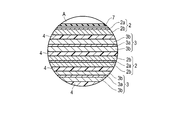
- FIG. 1 is a partially cutaway perspective view showing an example of a non-aqueous electrolyte battery according to a second embodiment.
- FIG. 2 is an enlarged cross-sectional view of part A of the non-aqueous electrolyte battery shown in FIG.
- FIG. 3 is a partially cutaway perspective view showing another example of the non-aqueous electrolyte battery according to the second embodiment.
- FIG. 4 is an exploded perspective view showing an example of the battery pack according to the third embodiment.
- FIG. 5 is a block diagram showing an example of the electric circuit of the battery pack shown in FIG.
- FIG. 6 is a 19F-NMR spectrum of a binder component extracted from the active material-containing layer of the positive electrode of Example 1.
- FIG. 7 is a 19F-NMR spectrum of a binder component extracted from the active material-containing layer of the positive electrode of Comparative Example 3.
- FIG. 8 is a particle size distribution chart of particles constituting the active material-containing layer of the positive electrode of Example 1.
- each figure is a schematic view for explaining the embodiment and promoting its understanding, and there are some differences in its shape, dimensions, ratio, etc. from the actual device, but these are described below and known techniques. The design can be changed as appropriate by taking into consideration.
- Electrodes are provided.
- the electrode contains an active material-containing layer.
- the active material-containing layer contains active material particles and a binder containing a polymer.
- the active material particles are Li a Ni (1-xy) Co x Mn y M z O 2 (0.9 ⁇ a ⁇ 1.2, 0 ⁇ x ⁇ 0.5, 0 ⁇ y ⁇ 0.5, 0 ⁇ z ⁇ 0.1, x ⁇ y, 0.4 ⁇ 1-xy ⁇ 0.8
- M is from B, Mg, Al, Si, Ca, Ti, Zn, Zr, Sn and W It contains a lithium-containing nickel-cobalt-manganese composite oxide represented by at least one element selected).
- the polymer has a repeating unit derived from vinylidene fluoride, and one or more peaks are present in the range of ⁇ 90 ppm or more and ⁇ 88 ppm or less in the nuclear magnetic resonance spectrum with 19F as the detection nucleus.
- Li a Ni (1-xy) Co x Mn y M z O 2 (0.9 ⁇ a ⁇ 1.2, 0 ⁇ x ⁇ 0.5, 0 ⁇ y ⁇ 0.5, 0 ⁇ z ⁇ 0 .1, x ⁇ y, 0.4 ⁇ 1-xy ⁇ 0.8, M is at least one selected from B, Mg, Al, Si, Ca, Ti, Zn, Zr, Sn and W.
- the active material particles containing the lithium-containing nickel-cobalt-manganese composite oxide represented by (element) have a higher Co content in the active material particles than the Mn content.
- an alkaline component for example, lithium hydroxide or lithium carbonate
- an alkaline component tends to remain in the active material.
- a residual alkaline component becomes a film component by being decomposed on the surface of the active material.
- gas for example, carbon dioxide, is generated by the decomposition of the residual alkaline component.
- the active material-containing layer contains a binder containing a polymer, the polymer has a repeating unit derived from vinylidene fluoride, and one or more peaks are present in the nuclear magnetic resonance spectrum with 19F as the detection nucleus. It should be in the range of -90 ppm or more and -88 ppm or less.
- the binder containing the above polymer adheres so as to cover at least a part of the surface of the active material and the residual alkaline component adhering to the surface of the active material, for example. As a result, the increase in resistance can be suppressed.
- the polymer further contains at least one functional group selected from the group consisting of a carbonyl group, an ester bond, and a chloro group.
- the interaction between the residual alkaline component adhering to the active material surface and the active material surface is large, and therefore, for example, the binder covers the residual alkaline component. Easy to adhere. As a result, the increase in resistance can be further suppressed.
- the active material-containing layer contains active material-containing layer-constituting particles containing active material particles and a binder, and the active material-containing layer-consisting particles have peaks A having different mode diameters and peaks A in a particle size distribution chart obtained by a laser diffraction / scattering method.
- Peak B exists, the mode diameter DA of peak A is smaller than the mode diameter DB of peak B, and the ratio PA / PB of the frequency PA in the mode diameter DA to the frequency PB in the mode diameter DB is 0.15 or more and 1.5 or less. It is desirable that it is within the range of.
- the presence of peaks A and B having different mode diameters improves the space filling property of the active material-containing particles. This makes it possible to improve the energy density of the non-aqueous electrolyte battery.
- the mode diameter DA of the peak A is smaller than the mode diameter DB of the peak B, and the ratio PA / PB of the frequency PA in the mode diameter DA and the frequency PB in the mode diameter DB is 0.15 or more. It is within the range of 1.5 or less.
- the interaction between the active material and the binder is sufficient, and the binder adheres so as to appropriately cover the surface of the active material and the residual alkaline component adhering to the surface of the active material. ing. As a result, the increase in resistance can be significantly suppressed.
- the electrode satisfying this has a surface in which the surface of the active material is coated with the above binder at a predetermined ratio. Therefore, the binder is attached to the active material surface and the residual alkaline component so as to sufficiently cover the residual alkaline component attached to the active material surface. As a result, the increase in resistance can be further suppressed.
- the average particle size (D50) in the particle size distribution chart is within the range of 1.5 ⁇ m or more and 6 ⁇ m or less.
- the active material-containing layer constituent particles satisfying the average particle size (D50) are active material particles because the binder is appropriately attached to the surface of the active material particles and the surface of the residual alkaline component adhering to the surface of the active material. A sufficient reaction area on the surface of the surface can be secured. As a result, the increase in resistance can be suppressed even more significantly.
- the electrode according to the first embodiment includes a current collector and an electrode mixture layer as an active material-containing layer supported on one side or both sides of the current collector.
- the electrode mixture layer contains active material particles and a binder.
- the active material contains a lithium-containing nickel-cobalt-manganese composite oxide.
- the lithium-containing nickel-cobalt-manganese composite oxide preferably has a composition formula of Li a Ni (1-xy) Co x Mn y M z O 2 .
- the subscript a is in the range of 0.9 ⁇ a ⁇ 1.2
- the subscript x is in the range of 0 ⁇ x ⁇ 0.5
- the subscript y is in the range of 0 ⁇ y ⁇ 0.5
- the subscript z is in the range of 0 ⁇ z ⁇ 0.1, satisfies x ⁇ y and 0.4 ⁇ 1-xy ⁇ 0.8
- M is B, Mg, Al, Si, Ca.
- Ti, Zn, Zr, Sn and W are preferably at least one element selected from the above.
- active materials may be used together as the active material.
- examples of other active materials include lithium-containing nickel oxide, lithium-containing nickel-cobalt composite oxide, lithium-containing manganese-cobalt composite oxide, and lithium-containing iron phosphate.
- the type of active material may be one type or two or more types.
- the active material may contain residual alkali.
- Residual alkali means lithium carbonate or lithium hydroxide that is not incorporated into the crystal structure of the active material.
- the amount of Li in these lithium compounds is not reflected in the amount of Li in the active material.
- the amount of Li in the composition formula is expressed. The amount of Li in the residual alkali is not reflected in a.
- the Ni atom in the crystal structure of the active material may move to the site of the Li atom which is an empty site.
- an excess amount of a lithium compound as a Li source is added. Therefore, the alkaline component that is not incorporated into the crystal structure tends to remain in the active material.
- the active material particles may be a mixture of primary particles and secondary particles.
- Secondary particles are aggregates of primary particles.
- the secondary particles are preferably densely packed with primary particles. This makes it possible to suppress a decrease in electrode density.
- the lithium-containing nickel-cobalt-manganese composite oxide has a high ratio of particles present as secondary particles to the total number of particles, for example. Further, the lithium-containing cobalt oxide has a high ratio of particles existing as primary particles to the total number of particles. Lithium-containing manganese oxide has a high ratio of particles present as primary particles to the total number of particles.
- the average particle size of the active material particles is, for example, 1 ⁇ m or more and 15 ⁇ m or less, preferably 3 ⁇ m or more and 10 ⁇ m or less.
- suitable secondary and primary particles that can reduce the initial resistance of the battery when some of the secondary particles are crushed by dispersion. The abundance ratio can be realized.
- the binder contains a polymer.
- the polymer preferably contains, for example, polyvinylidene fluoride (PVdF) as a basic skeleton. With such a polymer, the binder can cover the surface of the active material and the alkaline component remaining on the surface of the active material.
- PVdF polyvinylidene fluoride
- the polymer contained in the binder has a repeating unit derived from vinylidene fluoride, and has one or more peaks of -90 ppm or more in a nuclear magnetic resonance spectrum (19F-NMR spectrum) having 19F as a detection nucleus. It is preferably present in the range of 88 ppm or less.
- the peak to be analyzed here is a peak in which the intensity (%) of the peak with respect to the reference peak is 5% or more and exists in the range of ⁇ 90 ppm or more and ⁇ 88 ppm or less.
- the reference peak is a peak having the maximum intensity existing in the range of ⁇ 94 ppm or more and ⁇ 93 ppm or less.
- these target peaks when the chemical shift corresponding to the maximum intensity of one peak is 0.1 ppm or more away from the chemical shift corresponding to the maximum intensity of the other peak, each is regarded as an independent peak. ..
- the binder By satisfying the above conditions, it is possible to suppress an increase in electrode resistance.
- the reason is described below.
- the binder appropriately disperses the surface of the active material. A state of being attached so as to cover is obtained.
- the above binder can be present so as to cover the surface of the residual alkaline component adhering to the surface of the active material.
- the surfaces of the components or members constituting the electrode that may exist around the active material for example, the active material, the binder, the electrode mixture layer constituent particles, the conductive agent, and the surface of the current collector. Can be included.
- This strain may be, for example, a strain that deforms the basic skeleton of the binder, or may be a strain that changes the chemical structure of the basic skeleton of the binder itself. This strain is detected as one or more peaks in the range of ⁇ 90 ppm or more and ⁇ 88 ppm or less by subjecting the binder component extracted from the electrode mixture layer to 19F-NMR spectrum measurement.
- this peak when this peak is detected, it means that the binder and the surface of the active material interact with each other, and the binder is attached so as to appropriately cover the active material particles and the residual alkaline component.
- this peak when this peak is not detected, the binder and the surface of the active material do not sufficiently interact with each other, and the state in which the binder adheres so as to appropriately cover the active material particles and the residual alkaline component is not obtained. Means that.
- the binder adheres so as to excessively cover the surface of the active material, so that the redox reaction of Li ions on the surface of the active material is inhibited, so that the resistance at the electrode increases and the resistance of the non-aqueous electrolyte battery increases. Because.
- the reactivity on the surface of the active material can be suppressed to some extent, so that side reactions such as oxidative decomposition of the electrolyte solvent and electrolyte, and coatings that can be generated by the side reactions and become resistance components Growth is suppressed.
- the increase in the resistance of the electrode can be suppressed, and as a result, the increase in the resistance of the non-aqueous electrolyte battery can be suppressed.
- the binder adheres so as to cover the surface of the active material, in other words, the surface of the active material is protected by the binder, so that irreversible changes in the crystal structure that may occur during the redox reaction of Li ions are suppressed. To. This can suppress the increase in the resistance of the electrode and suppress the capacity deterioration of the non-aqueous electrolyte battery.
- the binder is preferably one in which a substituent other than polyvinylidene fluoride (PVdF) is introduced into the repeating structure of polyvinylidene fluoride (PVdF).
- the substituent preferably contains, for example, at least one functional group selected from the group consisting of a carbonyl group, an ester bond, and a chloro group.
- binder for example, polytetrafluoroethylene (PTFE), polyvinylidene fluoride (PVdF), or fluorine-based rubber is included.
- PTFE polytetrafluoroethylene
- PVdF polyvinylidene fluoride
- fluorine-based rubber is included.
- the type of binder used can be one or more.
- a binder of 0.2 parts by mass or more and 3.5 parts by mass or less with respect to 100 parts by mass of active material particles Since the binder is contained in the range of 0.2 parts by mass or more and 3.5 parts by mass or less with respect to 100 parts by mass of the active material particles, a binder having a high affinity with the active material is appropriately present. , Adheres so as to cover the surface of the active material appropriately. As a result, the increase in resistance of the electrode is suppressed, so that the increase in resistance of the non-aqueous electrolyte battery can be suppressed.
- the number of repeating units derived from polyvinylidene fluoride (PVdF) contained in the binder can be estimated by measuring the weight average molecular weight by the measuring method described later. That is, when the weight average molecular weight is large, the number of repeating units per molecule is also large.
- the constituent elements and chemical structure of the repeating unit itself can be identified, for example, by subjecting a sample obtained according to the method for taking out the electrode mixture layer described later to infrared spectroscopic analysis and measurement of a nuclear magnetic resonance spectrum.
- the electrode mixture layer may further contain a conductive agent.
- the conductive agent can increase the electron conductivity and suppress the contact resistance with the current collector.
- the conductive agent includes, for example, a carbon material such as acetylene black, carbon black, graphite, carbon nanofibers or carbon nanotubes.
- the type of the conductive agent used may be one type or two or more types.
- the electrode mixture layer may contain electrode mixture layer constituent particles as active material-containing layer constituent particles.
- the electrode mixture layer constituent particles include at least an agglomerate in which active material particles and a binder containing a polymer are aggregated. Further, the electrode mixture layer constituent particles may contain a conductive agent.
- the electrode mixture layer constituent particles have peaks A and B having different mode diameters in the particle size distribution chart obtained by the laser diffraction / scattering method.
- the mode diameter is the particle diameter corresponding to the peak top.
- the peak top is the highest frequency at the peak of interest.
- Having peaks with different mode diameters means that electrode mixture layer constituent particles having different particle sizes are present.
- the space filling property by the electrode mixture layer constituent particles is higher than that when only the electrode mixture layer constituent particles having a single particle diameter are present. improves. Therefore, it can contribute to the improvement of energy density.
- the electrode mixture layer constituent particles have a mode diameter DA of peak A smaller than the mode diameter DB of peak B, and the frequency PA in the mode diameter DA and the frequency PB in the mode diameter DB.
- the ratio PA / PB of is preferably in the range of 0.15 or more and 1.5 or less. More preferably, it is 0.2 or more and 1 or less.
- the abundance ratio of peak A attributed to the distribution of particles having a small particle size to peak B is sufficient. That is, it means that the dispersion is properly carried out and the dispersion is neither too small nor excessive.
- the interaction between the active material and the binder is sufficient, and the binder can be attached so as to sufficiently cover the surface of the active material and the residual alkaline component. Therefore, the increase in the resistance of the electrode can be suppressed, and the capacity deterioration of the non-aqueous electrolyte battery can be sufficiently suppressed.
- the average particle size (D50) of the electrode mixture layer constituent particles in the particle size distribution chart is preferably in the range of 1.5 ⁇ m or more and 6 ⁇ m or less, and more preferably in the range of 2 ⁇ m or more and 5 ⁇ m or less.
- the binder When the average particle diameter (D50) of the electrode mixture layer constituent particles is within the range of 1.5 ⁇ m or more and 6 ⁇ m or less, the binder is sufficiently adhered so as to cover the surface of the active material and the residual alkaline component. , Not excessive. Therefore, the reaction area on the surface of the active material exists appropriately, and the reaction resistance does not increase significantly. As a result, the reactivity on the surface of the active material is suppressed, that is, the reactivity on the electrode is suppressed, so that the effect of suppressing the capacity deterioration of the non-aqueous electrolyte battery can be sufficiently obtained.
- the current collector is preferably formed of an aluminum foil or an aluminum alloy foil.
- the average crystal grain size of the aluminum foil and the aluminum alloy foil is preferably 50 ⁇ m or less. More preferably, it is 30 ⁇ m or less. More preferably, it is 5 ⁇ m or less.
- the strength of the aluminum foil or the aluminum alloy foil can be dramatically increased, the positive electrode can be densified with a high press pressure, and the battery capacity can be increased. Can be made to.
- the thickness of the current collector is 20 ⁇ m or less, more preferably 15 ⁇ m or less.
- the purity of the aluminum foil is preferably 99% by mass or more.
- As the aluminum alloy an alloy containing one or more elements selected from the group consisting of magnesium, zinc and silicon is preferable.
- the content of transition metals such as iron, copper, nickel and chromium is preferably 1% by mass or less.
- the blending ratio of the active material, the conductive agent and the binder in the electrode mixture layer is preferably in the range of 80 to 95% by mass of the active material, 2 to 20% by mass of the conductive agent and 0.01 to 2.8% by mass of the binder. ..
- the electrode mixture layer preferably has a porosity of 20% or more and 50% or less.
- An electrode provided with an electrode mixture layer having such a porosity has a high density and has an excellent affinity with a non-aqueous electrolyte.
- a more preferable porosity is 25% or more and 40% or less.
- the density of the electrode mixture layer is preferably 2.5 g / cm 3 or more.
- the electrode mixture layer when the electrode is incorporated in a battery as a positive electrode, first, the positive electrode is taken out from the battery and immersed in ethyl methyl carbonate to remove Li salt and then dried. For the dried positive electrode, only the positive electrode mixture layer is stripped from the current collector with a spatula and immersed in an N-methylpyrrolidone (NMP) solvent. Then, a sample is obtained by dispersing the positive electrode mixture layer in the NMP solvent by using ultrasonic waves while being immersed in the NMP solvent.
- NMP N-methylpyrrolidone
- the ultrasonic treatment for obtaining the dispersion solvent is carried out, for example, by a sample supply system attached to a laser diffraction type distribution measuring device.
- the ultrasonic treatment is carried out at an output of 40 W for 300 seconds.
- the particle size distribution of the constituent particles is measured using a laser diffraction type distribution measuring device.
- the measuring device for example, Microtrack MT3100II manufactured by Microtrack Bell Co., Ltd. can be used.
- peak A and peak B are determined according to the above definition. Further, from this particle size distribution chart, the average particle size (D50) of the particles constituting the electrode mixture layer can be determined.
- ⁇ Measurement method of 19F-NMR spectrum of binder component extracted from electrode mixture layer The sample obtained by the above method is centrifuged, and the supernatant containing the binder from which the solid content has been removed is separated to obtain a sample for 19F-NMR measurement. By measuring this sample, it is possible to measure the state of 19F in the electrode mixture layer instead of the state of 19F existing in the electrolytic solution.
- the measuring device for example, JEM-ECA500 manufactured by JEOL can be used.
- the magnetic field lock solvent is a deuterium solvent (dimethyl sulfoxide-d6 (DMSO-d6)), and the reference substance is 3,5-bistrifluoromethylbenzoic acid (3,5-BTFMBA).
- the presence or absence and the number of peaks appearing in the range of -95 ppm or more and -87 ppm or less and the intensity (%) of the peak with respect to the reference peak is 5% or more according to the above definition. Analyze by checking within the range of -90 ppm or more and -88 ppm or less.
- ⁇ Measurement method of weight average molecular weight of binder component extracted from electrode mixture layer For example, an N-methyl-2-methylpyrrolidone solvent containing 0.1 mol / L lithium chloride is added to the sample obtained by the above method, the mixture is stirred at 75 to 85 ° C. for 90 minutes, and filtered through a filter. By doing so, it becomes a sample for measuring the weight average molecular weight.
- a gel permeation chromatograph GPC
- the detector is a differential refractive index detector, the column is, for example, Showa Denko's Shodex KF-806M, the flow rate is 0.5 mL / min, and the column temperature is 40 ° C.
- the active material, the conductive material and the binder are suspended in a suitable solvent to obtain a dispersion solution.
- a slurry for forming an electrode mixture layer is obtained through a dispersion step of carrying out a bead mill or the like on this dispersion solution.
- the obtained slurry is applied to one side or both sides of the current collector and dried to obtain a laminated body in which the electrode mixture layers are laminated.
- An electrode is produced by pressing the laminate and cutting it if necessary. Conductive tabs may be welded to the current collector.
- the binder can be attached to the surface of the active material particles so as to sufficiently cover the surface of the active material particles. Therefore, in order for the peak to appear within the above range, it is preferable to perform dispersion using a large collision energy such as bead mill dispersion. Specifically, it is preferable to perform bead mill dispersion such as a sand grinder on a paste-like solution in which a material for forming an electrode mixture layer and a solvent such as N-methylpyrrolidone (NMP) are mixed.
- NMP N-methylpyrrolidone
- the binder When the material of the beads, the bead diameter, the bead filling rate, the number of rotations of the blades, and the processing time are adjusted in a complex manner to strongly disperse the dispersion solution, for example, the binder sufficiently covers the surface of the active material particles. Since it can adhere, a peak appears in the range of -90 ppm or more and -88 ppm or less in the 19F-NMR spectrum.
- the material of the beads, the diameter of the beads, the filling rate of the beads, the number of rotations of the blades, and the treatment time are adjusted in a complex manner to weakly disperse the dispersion solution, for example, the binder sufficiently covers the surface of the active material particles. Since it cannot be adhered, no peak appears in the range of -90 ppm or more and -88 ppm or less in the 19F-NMR spectrum.
- the ratio PA / PB also exists in the range of 0.15 or more and 1.5 or less.
- an electrode includes an active material-containing layer containing active material particles and a binder containing a polymer.
- the active material particles are Li a Ni (1-xy) Co x Mn y M z O 2 (0.9 ⁇ a ⁇ 1.2, 0 ⁇ x ⁇ 0.5, 0 ⁇ y ⁇ 0.5, 0 ⁇ z ⁇ 0.1, x ⁇ y, 0.4 ⁇ 1-xy ⁇ 0.8, M is from B, Mg, Al, Si, Ca, Ti, Zn, Zr, Sn and W It contains a lithium-containing nickel-cobalt-manganese composite oxide represented by at least one element selected).
- the polymer has a repeating unit derived from vinylidene fluoride, and one or more peaks are present in the range of ⁇ 90 ppm or more and ⁇ 88 ppm or less in the nuclear magnetic resonance spectrum with 19F as the detection nucleus. Since it has such a configuration, the electrode according to the first embodiment can suppress an increase in resistance. As a result, this non-aqueous electrolyte battery can exhibit excellent input / output characteristics and excellent life characteristics.
- the non-aqueous electrolyte battery according to the second embodiment includes a positive electrode, a negative electrode, a non-aqueous electrolyte, and an exterior member.
- the positive electrode current collector can include a portion that does not support a positive electrode active material-containing layer on the surface. This portion can serve as a positive electrode tab.
- the positive electrode may include a positive electrode tab that is separate from the positive electrode current collector.
- the negative electrode includes a negative electrode active material-containing layer as a negative electrode mixture layer.
- the negative electrode may further include a negative electrode current collector.
- the negative electrode active material-containing layer can be supported on at least one surface of the negative electrode current collector. That is, the negative electrode current collector can support the negative electrode active material-containing layer on one side or both sides. Further, the negative electrode current collector can include a portion that does not support the negative electrode active material-containing layer on the surface. This portion can serve as a negative electrode tab. Alternatively, the negative electrode may include a negative electrode tab that is separate from the negative electrode current collector.
- the positive electrode and the negative electrode can form an electrode group.
- the positive electrode active material-containing layer and the negative electrode active material-containing layer can face each other via, for example, a separator.
- the electrode group can have various structures.
- the electrode group can have a stack type structure.
- the electrode group having a stack type structure can be obtained, for example, by alternately stacking a plurality of positive electrodes and a plurality of negative electrodes with a separator sandwiched between the positive electrode active material-containing layer and the negative electrode active material-containing layer.
- the electrode group can have a wound structure.
- one separator, one negative electrode, another separator, and one positive electrode are laminated in this order to form a laminated body, and this laminated body is formed. It can be obtained by winding.
- the non-aqueous electrolyte battery according to the second embodiment may further include a positive electrode terminal and a negative electrode terminal.
- a part of the positive electrode terminal is electrically connected to a part of the positive electrode, so that the positive electrode terminal can function as a conductor for electrons to move between the positive electrode and the external terminal.
- the positive electrode terminal can be connected to, for example, a positive electrode current collector, particularly a positive electrode tab.
- the negative electrode terminal can act as a conductor for electrons to move between the negative electrode and the external terminal by electrically connecting a part of the negative electrode terminal to a part of the negative electrode.
- the negative electrode terminal can be connected to, for example, a negative electrode current collector, particularly a negative electrode tab.
- the exterior member accommodates the electrode group and the non-aqueous electrolyte.
- the non-aqueous electrolyte can be impregnated in the electrode group within the exterior member.
- a part of each of the positive electrode terminal and the negative electrode terminal can also be extended from the exterior member.
- the positive electrode, the negative electrode, the non-aqueous electrolyte, the separator and the exterior member will be described in more detail.
- ⁇ Positive electrode> for the positive electrode, for example, the electrode of the first embodiment is used.
- the negative electrode has a negative electrode current collector and a negative electrode active material-containing layer supported on one or both sides of the negative electrode current collector and containing a negative electrode active material, a negative electrode conductive agent, and a binder.
- the negative electrode active material contains a titanium-containing oxide.
- the type of the negative electrode active material can be one type or two or more types.
- titanium-containing oxides include lithium titanium composite oxides, anatase-type titanium-containing oxides, rutile-type titanium-containing oxides, bronze-type titanium-containing oxides, orthocrystalline titanium-containing oxides, and monooblique. Includes a crystalline niobium titanium-containing oxide and a metal composite oxide containing Ti and at least one element selected from the group consisting of P, V, Sn, Cu, Ni, Nb and Fe.
- the lithium titanium composite oxide includes a lithium titanium oxide and a lithium titanium composite oxide in which some of the constituent elements of the lithium titanium oxide are replaced with different elements.
- Lithium-titanium oxide includes, for example, lithium titanate having a spinel-type structure (for example, Li 4 + x Ti 5 O 12 (x is a value that changes with charge and discharge, 0 ⁇ x ⁇ 3)), and rams delite-type lithium acid.
- Lithium for example, Li 2 + y Ti 3 O 7 (y is a value that changes with charge and discharge, 0 ⁇ y ⁇ 3)
- Lithium for example, Li 2 + y Ti 3 O 7 (y is a value that changes with charge and discharge, 0 ⁇ y ⁇ 3)
- the molar ratio of oxygen is formally shown as 12 for spinel type Li 4 + x Ti 5 O 12 and 7 for rams delite type Li 2 + y Ti 3 O 7 , but these are due to the influence of oxygen non-stoicometry and the like. The value of can change.
- Examples of the metal composite oxide containing Ti and at least one element selected from the group consisting of P, V, Sn, Cu, Ni, Nb and Fe include TiO 2- P 2 O 5 and TiO.
- This metal composite oxide preferably has a low crystallinity and has a microstructure in which a crystalline phase and an amorphous phase coexist or the amorphous phase alone exists. With such a microstructure, the cycle performance can be significantly improved.
- composition of anatase-type, rutile-type, and bronze-type titanium-containing oxides can be represented by TiO 2 .
- the orbital titanium-containing oxide is represented by the general formula Li 2 + w Na 2-x M1 y Ti 6-z M2 z O 14 + ⁇ , M1 is Cs and / or K, and M2 is Zr, Sn, V. , Nb, Ta, Mo, W, Fe, Co, Mn, and Al, and examples thereof include compounds containing at least one of 0 ⁇ w ⁇ 4, 0 ⁇ x ⁇ 2, 0 ⁇ y ⁇ 2, 0 ⁇ z. ⁇ 6, ⁇ 0.5 ⁇ ⁇ ⁇ 0.5.
- the monoclinic niobium-titanium-containing oxide is represented by the general formula Li x Ti 1-y M3 y Nb 2-z M4 z O 7 + ⁇ , and M3 is composed of Zr, Si, Sn, Fe, Co, Mn and Ni.
- M4 being at least one compound selected from the group consisting of V, Nb, Ta, Mo, W and Bi, 0 ⁇ x ⁇ 5, 0 ⁇ y. ⁇ 1, 0 ⁇ z ⁇ 2, ⁇ 0.3 ⁇ ⁇ ⁇ 0.3.
- a preferable negative electrode active material is one containing a lithium titanium composite oxide.
- the negative electrode containing a titanium-containing oxide such as a lithium-titanium composite oxide has an occlusion potential of 0.4 V (vs. Li / Li + ) or more, the surface of the negative electrode when input / output at a large current is repeated. It is possible to prevent the precipitation of metallic lithium on the above.
- the negative electrode active material may contain an active material other than the lithium titanium composite oxide, but in that case, an active material having a Li storage potential of 0.4 V (vs. Li / Li + ) or more should be used. Is desirable.
- binder examples include polytetrafluoroethylene (PTFE), polyvinylidene fluoride (PVdF), fluorine-based rubber, styrene-butadiene rubber (SBR), carboxymethyl cellulose (CMC), polyimide, and polyamide.
- PTFE polytetrafluoroethylene
- PVdF polyvinylidene fluoride
- SBR styrene-butadiene rubber
- CMC carboxymethyl cellulose
- polyimide polyimide
- polyamide polyamide
- Examples of the negative electrode conductive agent include carbon black such as acetylene black and Ketjen black, graphite, carbon fiber, carbon nanotube, and fullerene.
- the type of the conductive agent can be one type or two or more types.
- the blending ratio of the negative electrode active material, the conductive agent and the binder in the negative electrode active material-containing layer is 70% by mass or more and 95% by mass or less of the negative electrode active material, 0% by mass or more and 25% by mass or less of the conductive agent, and 2% by mass of the binder. It is preferably 10% by mass or less.
- the conductive agent in a proportion of 0% by mass or more, excellent large current characteristics due to high current collecting performance can be obtained.
- the amount of the binder to 2% by mass or more, the binding property between the negative electrode active material-containing layer and the negative electrode current collector can be improved and the cycle characteristics can be improved.
- the negative electrode conductive agent and the binder are preferably 10% by mass or less, respectively.
- the current collector is preferably an aluminum foil or an aluminum alloy foil that is electrochemically stable in a potential range noble than 1.0 V.
- a negative electrode active material, a negative electrode conductive agent, and a binder are suspended in an appropriate solvent, and the obtained slurry is applied to a negative electrode current collector and dried to prepare a negative electrode active material-containing layer. It is produced by applying a press.
- the negative electrode active material, the negative electrode conductive agent, and the binder may be formed in pellet form and used as the negative electrode active material-containing layer.
- the negative electrode active material-containing layer preferably has a porosity of 20% or more and 50% or less.
- the negative electrode active material-containing layer having such a porosity has an excellent affinity with the non-aqueous electrolyte, and it is possible to increase the density.
- a more preferable porosity is 25% or more and 40% or less.
- the density of the negative electrode active material-containing layer is preferably 2.0 g / cm 3 or more.
- Non-aqueous electrolyte examples include a liquid non-aqueous electrolyte prepared by dissolving the electrolyte in a non-aqueous solvent, a gel-like non-aqueous electrolyte obtained by combining a liquid non-aqueous electrolyte and a polymer material, and the like.
- the electrolytes are, for example, lithium perchlorate (LiClO 4 ), lithium hexafluorophosphate (LiPF 6 ), lithium tetrafluoroborate (LiBF 4 ), lithium arsenic hexafluorophosphate (LiAsF 6 ), lithium difluorophosphate.
- Lithium salts such as (LiPO 2 F 2 ), lithium trifluoromethanesulfonate (LiCF 3 SO 3 ), bistrifluoromethylsulfonylimide lithium [LiN (CF 3 SO 2 ) 2 ], lithium tetrafluorofluorophosphate (LiAlF 4 ) Can be mentioned.
- These electrolytes may be used alone or in admixture of two or more.
- the electrolyte is preferably dissolved in a non-aqueous solvent in the range of 0.5 mol / L or more and 2.5 mol / L or less.
- Non-aqueous solvents are, for example, cyclic carbonates such as ethylene carbonate (EC) and propylene carbonate (PC); chain carbonates such as dimethyl carbonate (DMC), ethyl methyl carbonate (EMC) and diethyl carbonate (DEC); tetrahydrofuran (THF).
- Cyclic ethers such as 2-methyltetrahydrofuran (2MeTHF); chain ethers such as dimethoxyethane (DME); cyclic esters such as ⁇ -butyrolactone (GBL); organic solvents such as acetonitrile (AN).
- EC ethylene carbonate
- PC propylene carbonate
- chain carbonates such as dimethyl carbonate (DMC), ethyl methyl carbonate (EMC) and diethyl carbonate (DEC)
- THF tetrahydrofuran
- Cyclic ethers such as 2-methyltetrahydrofuran (2MeTHF)
- the separator is not particularly limited as long as it has insulating properties, and a porous film or non-woven fabric made of a polymer such as polyolefin, cellulose, polyethylene terephthalate, polyvinylidene fluoride (PVdF) or vinylon can be used.
- the material of the separator may be one kind, or two or more kinds may be used in combination.
- the exterior member may be formed of a laminated film or may be composed of a metal container. When using a metal container, the lid can be integrated with or separate from the container.
- the wall thickness of the metal container is more preferably 0.5 mm or less and 0.2 mm or less.
- Examples of the shape of the exterior member include a flat type, a square type, a cylindrical type, a coin type, a button type, a sheet type, and a laminated type. In addition to a small battery loaded in a portable electronic device or the like, a large battery loaded in a two-wheeled or four-wheeled automobile may be used.
- the wall thickness of the laminated film exterior member is 0.2 mm or less.
- An example of a laminated film is a multilayer film containing a resin film and a metal layer arranged between the resin films.
- the metal layer is preferably an aluminum foil or an aluminum alloy foil for weight reduction.
- the resin film for example, a polymer material such as polypropylene (PP), polyethylene (PE), nylon, or polyethylene terephthalate (PET) can be used.
- the laminated film can be sealed into the shape of an exterior member by heat fusion.
- the metal container is made of aluminum or aluminum alloy.
- the aluminum alloy an alloy containing elements such as magnesium, zinc, and silicon is preferable.
- the content of transition metals such as iron, copper, nickel and chromium is 100 ppm or less in order to dramatically improve long-term reliability and heat dissipation in a high temperature environment.
- the metal container made of aluminum or an aluminum alloy has an average crystal grain size of 50 ⁇ m or less, more preferably 30 ⁇ m or less, and further preferably 5 ⁇ m or less.
- the average crystal grain size By setting the average crystal grain size to 50 ⁇ m or less, the strength of the metal container made of aluminum or an aluminum alloy can be dramatically increased, and the thickness of the container can be further reduced. As a result, it is possible to realize a non-aqueous electrolyte battery suitable for in-vehicle use, which is lightweight, has high output, and has excellent long-term reliability.
- FIG. 1 is a partially cutaway perspective view showing an example of a non-aqueous electrolyte battery according to the second embodiment.
- FIG. 2 is an enlarged cross-sectional view of part A of the non-aqueous electrolyte battery shown in FIG.
- the non-aqueous electrolyte battery 100 shown in FIGS. 1 and 2 includes a flat electrode group 1.
- the flat electrode group 1 includes a negative electrode 2, a positive electrode 3, and a separator 4.
- the electrode group 1 has a structure in which a negative electrode 2 and a positive electrode 3 are spirally wound so as to have a flat shape with a separator 4 interposed between them.
- the wound electrode group will be described here, the electrode group may be a laminated electrode group in which a plurality of negative electrodes 2, a separator 4, and a positive electrode 3 are laminated.
- the negative electrode 2 includes a negative electrode current collector 2a and a negative electrode active material-containing layer 2b supported on the negative electrode current collector 2a.
- the positive electrode 3 includes a positive electrode current collector 3a and a positive electrode active material-containing layer 3b supported on the positive electrode current collector 3a.
- a band-shaped negative electrode terminal 5 is electrically connected to the negative electrode 2. More specifically, the negative electrode terminal 5 is connected to the negative electrode current collector 2a. Further, a band-shaped positive electrode terminal 6 is electrically connected to the positive electrode 3. More specifically, the positive electrode terminal 6 is connected to the positive electrode current collector 3a.
- the non-aqueous electrolyte battery 100 further includes an outer container 7 made of a laminated film as a container. That is, the non-aqueous electrolyte battery 100 includes an exterior material made of an exterior container 7 made of a laminated film.
- the electrode group 1 is housed in an outer container 7 made of a laminated film. However, the ends of the negative electrode terminal 5 and the positive electrode terminal 6 extend from the outer container 7.
- a non-aqueous electrolyte (not shown) is housed in the outer container 7 made of a laminated film. The non-aqueous electrolyte is impregnated in the electrode group 1.
- the peripheral portion of the outer container 7 is heat-sealed, whereby the electrode group 1 and the non-aqueous electrolyte are sealed.
- FIG. 3 is a partially cutaway perspective view showing another example of the non-aqueous electrolyte battery according to the second embodiment.
- the non-aqueous electrolyte battery 200 shown in FIG. 3 differs from the non-aqueous electrolyte battery 100 shown in FIGS. 1 and 2 in that the exterior material is composed of a metal container 17a and a sealing plate 17b.
- the flat electrode group 11 includes a negative electrode, a positive electrode, and a separator, similarly to the electrode group 1 in the non-aqueous electrolyte battery 100 shown in FIGS. 1 and 2. Further, the electrode group 11 has the same structure as the electrode group 1. However, in the electrode group 11, the negative electrode tab 15a and the positive electrode tab 16a are connected to the negative electrode and the positive electrode, respectively, instead of the negative electrode terminal 5 and the positive electrode terminal 6, as will be described later.
- such an electrode group 11 is housed in a metal container 17a.
- the metal container 17a further houses a non-aqueous electrolyte (not shown).
- the metal container 17a is sealed by a metal sealing plate 17b.
- the metal container 17a and the sealing plate 17b form, for example, an outer can as an outer material.
- One end of the negative electrode tab 15a is electrically connected to the negative electrode current collector, and the other end is electrically connected to the negative electrode terminal 15.
- One end of the positive electrode tab 16a is electrically connected to the positive electrode current collector, and the other end is electrically connected to the positive electrode terminal 16 fixed to the sealing plate 17b.
- the positive electrode terminal 16 is fixed to the sealing plate 17b via an insulating member 17c.
- the positive electrode terminal 16 and the sealing plate 17b are electrically insulated by an insulating member 17c.
- the non-aqueous electrolyte battery according to the second embodiment includes the electrodes according to the first embodiment. Therefore, the non-aqueous electrolyte battery according to the second embodiment can realize excellent input / output characteristics and cycle life characteristics.
- a battery pack is provided.
- This battery pack includes the non-aqueous electrolyte battery according to the second embodiment.
- the battery pack according to the third embodiment may also include a plurality of non-aqueous electrolyte batteries.
- the plurality of non-aqueous electrolyte batteries can be electrically connected in series or electrically in parallel.
- a plurality of non-aqueous electrolyte batteries can be connected in series and in parallel.
- the battery pack according to the third embodiment may include, for example, five non-aqueous electrolyte batteries. These non-aqueous electrolyte batteries can be connected in series. Further, the non-aqueous electrolyte batteries connected in series can form an assembled battery. That is, the battery pack according to the third embodiment may also include an assembled battery.
- the battery pack according to the third embodiment can include a plurality of assembled batteries.
- a plurality of assembled batteries can be connected in series, in parallel, or in a combination of series and parallel.
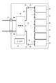
- FIG. 4 is an exploded perspective view showing an example of the battery pack according to the third embodiment.
- FIG. 5 is a block diagram showing an example of the electric circuit of the battery pack shown in FIG.
- the battery pack 20 shown in FIGS. 4 and 5 includes a plurality of cell cells 21.
- the cell 21 may be an example of a flat non-aqueous electrolyte battery 100 according to a second embodiment described with reference to FIG.
- the plurality of cells 21 are laminated so that the negative electrode terminals 5 and the positive electrode terminals 6 extending to the outside are aligned in the same direction, and are fastened with adhesive tape 22 to form the assembled battery 23. These cell batteries 21 are electrically connected in series with each other as shown in FIG.
- the printed wiring board 24 is arranged so as to face the side surface on which the negative electrode terminal 5 and the positive electrode terminal 6 of the cell 21 extend. As shown in FIG. 5, the printed wiring board 24 is equipped with a thermistor 25, a protection circuit 26, and a terminal 27 for energizing an external device. An insulating plate (not shown) is attached to the printed wiring board 24 on the surface facing the assembled battery 23 in order to avoid unnecessary connection with the wiring of the assembled battery 23.
- the positive electrode side lead 28 is connected to the positive electrode terminal 6 located at the bottom layer of the assembled battery 23, and the tip thereof is inserted into the positive electrode side connector 29 of the printed wiring board 24 and electrically connected.
- the negative electrode side lead 30 is connected to the negative electrode terminal 5 located on the uppermost layer of the assembled battery 23, and the tip thereof is inserted into the negative electrode side connector 31 of the printed wiring board 24 and electrically connected. These connectors 29 and 31 are connected to the protection circuit 26 through the wirings 32 and 33 formed on the printed wiring board 24.
- the thermistor 25 detects the temperature of the cell 21 and the detection signal is transmitted to the protection circuit 26.
- the protection circuit 26 can cut off the positive side wiring 34a and the negative side wiring 34b between the protection circuit 26 and the energizing terminal 27 to the external device under predetermined conditions.
- An example of the predetermined condition is when the detection temperature of the thermistor 25 becomes equal to or higher than the predetermined temperature.
- another example of the predetermined condition includes the case where an overcharge, an overdischarge, an overcurrent, or the like of the cell 21 is detected.
- the detection of overcharging or the like is performed on the individual cell 21 or the entire assembled battery 23. When detecting the individual cell 21, the battery voltage may be detected, or the positive electrode potential or the negative electrode potential may be detected.
- a lithium electrode used as a reference electrode is inserted into each cell 21.
- a wiring 35 for voltage detection is connected to each of the cell 21. A detection signal is transmitted to the protection circuit 26 through these wires 35.
- a protective sheet 36 made of rubber or resin is arranged on each of the three side surfaces of the assembled battery 23 except for the side surface on which the positive electrode terminal 6 and the negative electrode terminal 5 protrude.
- the assembled battery 23 is stored in the storage container 37 together with the protective sheet 36 and the printed wiring board 24. That is, the protective sheet 36 is arranged on both inner surfaces in the long side direction and one inner side surface in the short side direction of the storage container 37, and the printed wiring board 24 is arranged on the other inner side surface in the short side direction.
- the assembled battery 23 is located in a space surrounded by the protective sheet 36 and the printed wiring board 24.
- the lid 38 is attached to the upper surface of the storage container 37.
- a heat-shrinkable tape may be used instead of the adhesive tape 22 to fix the assembled battery 23.
- protective sheets are arranged on both side surfaces of the assembled battery, the heat-shrinkable tape is circulated, and then the heat-shrinkable tape is heat-shrinked to bind the assembled battery.
- the cells 21 are connected in series in FIGS. 4 and 5, they may be connected in parallel in order to increase the battery capacity. Further, the assembled battery packs can be connected in series and / or in parallel.
- the mode of the battery pack according to the third embodiment is appropriately changed depending on the application.
- those in which cycle performance with high current performance is desired are preferable.
- Specific applications include power supplies for digital cameras, two-wheeled to four-wheeled hybrid electric vehicles, two-wheeled to four-wheeled electric vehicles, and in-vehicle use such as assisted bicycles.
- the battery pack according to the third embodiment is particularly suitable for in-vehicle use.
- the battery pack according to the third embodiment includes the non-aqueous electrolyte battery according to the second embodiment. Therefore, the battery pack according to the third embodiment can realize excellent input / output characteristics and cycle life characteristics.
- Example 1 In Example 1, the positive electrode and the non-aqueous electrolyte battery of Example 1 were produced by the following procedure.
- particles of a lithium-containing nickel-cobalt-manganese composite oxide represented by the composition formula LiNi 0.6 Co 0.25 Mn 0.15 O 2 having an average particle diameter of 5 ⁇ m were prepared.
- a polymer material having a carbonyl group-containing substituent (polyvinylidene fluoride (PVdF) with a carbonyl group-containing substituent) having a basic skeleton of graphite and acetylene black as a conductive agent and polyvinylidene fluoride (PVdF) as a binder was prepared. ..
- LiNi 0.6 Co 0.25 Mn 0.15 O 2 , graphite, acetylene black, and a polymer material were dispersed in N-methylpyrrolidone (NMP) at a mass ratio of 89: 5: 5: 1. .. In this way, a paste-like dispersion solution was obtained. Beadmill dispersion was carried out on the obtained dispersion solution to uniformly disperse the conductive agent and the active material to obtain a slurry.
- NMP N-methylpyrrolidone
- the bead mill dispersion was performed using a bead type wet fine particle dispersion crusher: sand grinder manufactured by IMEX Co., Ltd.
- As the medium glass beads having a bead diameter of 2 mm were used, and the bead filling rate was 45%.
- the dispersion conditions were a rotation speed of 800 rpm and a processing time of 60 minutes.
- the slurry obtained after carrying out the bead mill dispersion was uniformly applied to both the front and back surfaces of a current collector made of a strip-shaped aluminum foil having a thickness of 20 ⁇ m, and dried to form a positive electrode active material-containing layer. Then, the dried strip was pressed to obtain a positive electrode.
- a spinel-structured Li 4 Ti 5 O 12 was prepared as the negative electrode active material, graphite was prepared as the conductive agent, and polyvinylidene fluoride (PVdF) was prepared as the binder.
- a slurry was prepared by dispersing Li 4 Ti 5 O 12 , graphite, and polyvinylidene fluoride (PVdF) in N-methylpyrrolidone (NMP) at a mass ratio of 85:10: 5. The obtained slurry was uniformly applied to both the front and back surfaces of a current collector made of a strip-shaped aluminum foil having a thickness of 20 ⁇ m, and dried to form a negative electrode active material-containing layer. Next, the dried strip was pressed to obtain a negative electrode.
- ⁇ Preparation of electrode group> As the separator, two polyethylene resin separators were prepared. Next, the separator, the positive electrode, the separator and the negative electrode were laminated in this order to form a laminate. The obtained laminate was spirally wound using a winding core so that the negative electrode was located on the outermost circumference. Next, after the winding core was pulled out, a wound electrode group was produced by pressing while heating.
- a mixed solvent was prepared by mixing ethylene carbonate (EC) and ethyl methyl carbonate (EMC) in a volume ratio of 1: 2.
- a non-aqueous electrolyte was prepared by dissolving lithium hexafluorophosphate (LiPF 6 ) as an electrolyte salt in this mixed solvent so as to have a concentration of 1 M (mol / L).
- a positive electrode terminal and a negative electrode terminal were attached to each of the positive electrode and the negative electrode of the wound electrode group obtained as described above, and the electrode group was placed in a laminated container.
- the non-aqueous electrolyte was injected from the injection port into the container containing the electrode group.
- a non-aqueous electrolyte battery was produced by sealing the liquid injection port. In this way, a flat non-aqueous electrolyte battery having a thickness of 3.5 mm, a width of 35 mm, a height of 65 mm, and a mass of 25 g was produced.
- Example 2 In Example 2, as shown in Table 1, polyvinylidene fluoride (PVdF) was used as a binder when producing the positive electrode, and the treatment time for bead mill dispersion was set to 50 minutes. A battery was prepared in the same manner as in the above.
- PVdF polyvinylidene fluoride
- Example 3 In Example 3, as shown in Table 1, polyvinylidene fluoride (PVdF) having a chloro group-containing substituent introduced as a binder was added in an amount of 1.5% by mass as a binder when preparing the positive electrode. A battery was prepared in the same manner as described in Example 1.
- PVdF polyvinylidene fluoride
- Example 4 In Example 4, as shown in Table 1, when preparing the positive electrode, LiNi 0.5 Co 0.3 Mn 0.2 O 2 was used as the positive electrode active material, and a polyvinylidene fluoride containing an ester bond-containing substituent was introduced as the binder. A battery was prepared by the same method as described in Example 1 except that vinylidene fluoride (PVdF) was added in an amount of 1.5% by mass and the treatment time for bead mill dispersion was 50 minutes.
- PVdF vinylidene fluoride
- Example 5 In Example 5, as shown in Table 1, it is described in Example 1 except that LiNi 0.7 Co 0.18 Mn 0.12 O 2 was used as the positive electrode active material when producing the positive electrode. A battery was prepared in the same manner as in.
- Example 6 In Example 6, as shown in Table 1, it is described in Example 1 except that LiNi 0.8 Co 0.15 Mn 0.05 O 2 was used as the positive electrode active material when producing the positive electrode. A battery was prepared in the same manner as in.
- Example 7 In Example 7, as shown in Table 1, the example was carried out except that LiNi 0.6 Co 0.24 Mn 0.15 Al 0.01 O 2 was used as the positive electrode active material when producing the positive electrode. A battery was prepared in the same manner as described in 1.
- Example 8 In Example 8, as shown in Table 1, it is described in Example 1 except that the filling rate of the bead mill dispersion was 40% by mass, the rotation speed was 500 rpm, and the treatment time was 50 minutes when producing the positive electrode. A battery was prepared in the same manner as in the above.
- Example 9 In Example 9, as shown in Table 1, the same as that described in Example 1 except that the filling rate of the bead mill dispersion was 50% by mass and the treatment time was 100 minutes when preparing the positive electrode. Batteries were made by the method.
- Comparative Example 1 In Comparative Example 1, as shown in Table 1, when producing the positive electrode, the amount of the binder added was 1.5% by mass, the filling rate of the bead mill dispersion was 40% by mass, the rotation speed was 500 rpm, and the treatment was performed. A battery was prepared in the same manner as described in Example 1 except that the time was set to 30 minutes.
- Comparative Example 2 In Comparative Example 2, as shown in Table 1, when producing the positive electrode, the amount of the binder added was 2.5% by mass, the filling rate of the bead mill dispersion was 50% by mass, and the treatment time was 120 minutes. A battery was produced in the same manner as described in Example 1 except for the above.
- Comparative Example 3 In Comparative Example 3, as shown in Table 1, polyvinylidene fluoride (PVdF) was added as a binder in an amount of 2.5% by mass at the time of producing the positive electrode, the filling rate of the bead mill dispersion was 40% by mass, and the number of rotations was 40%.
- a battery was prepared in the same manner as described in Example 1 except that the treatment time was set to 500 rpm and the treatment time was 30 minutes.
- Comparative Example 4 In Comparative Example 4, as shown in Table 1, when producing the positive electrode, LiNi 0.5 Co 0.2 Mn 0.3 O 2 was used as the positive electrode active material, and polyvinylidene fluoride (PVdF) 2 was used as the binder. Batteries were made in the same manner as described in Example 1, except that they were added in an amount of .5% by weight.
- Comparative Example 5 (Comparative Example 5)
- LiNi 0.5 Co 0.2 Mn 0.3 O 2 was used as the positive electrode active material when producing the positive electrode, and the amount of the binder added was 2.5% by mass. Batteries were prepared in the same manner as described in Example 1 except that they were added in the amount of.
- Comparative Example 6 In Comparative Example 6, as shown in Table 1, it was described in Example 1 except that LiNi 1/3 Co 1/3 Mn 1/3 O 2 was used as the positive electrode active material when producing the positive electrode. A battery was prepared in the same manner as in.
- FIGS. 6 and 7 show the results of 19F-NMR spectrum measurement according to the method described above of the binder component extracted from the positive electrode active material-containing layer provided in the non-aqueous electrolyte batteries of Example 1 and Comparative Example 3. Shown.
- the spectrum shown in FIG. 6 is one 19F-NMR spectrum of the binder component extracted from the active material-containing layer of the positive electrode of Example 1.
- the spectrum shown in FIG. 7 is one 19F-NMR spectrum of the binder component extracted from the active material-containing layer of the positive electrode of Comparative Example 3.
- the horizontal axis of FIGS. 6 and 7 is the chemical shift (ppm).
- the vertical axis of FIGS. 6 and 7 is the relative strength.
- Table 2 shows the number of peaks in the range of ⁇ 90 ppm or more and ⁇ 88 ppm or less, which was counted according to the method described above.
- the reference peak p0 exists in the range of -94 ppm or more and -93 ppm or less. From the spectrum shown in FIG. 6, in Example 1, peaks p1 to p3 exist in the range of ⁇ 90 ppm or more and ⁇ 88 ppm or less, that is, one or more peaks exist in the range of ⁇ 90 ppm or more and ⁇ 88 ppm or less. You can see that. On the other hand, in the spectrum shown in FIG. 7, the reference peak p0 exists in the range of ⁇ 94 ppm or more and ⁇ 93 ppm or less. From the spectrum shown in FIG.
- the reference peak p0 exists in the range of -94 ppm or more and -93 ppm or less, and as shown in Table 2, one or more peaks exist in the range of -90 ppm or more and -88 ppm or less. It was confirmed. Further, in Comparative Examples 2 to 6, the reference peak p0 existed in the range of -94 ppm or more and -93 ppm or less, but as shown in Table 2, no peak was confirmed in the range of -90 ppm or more and -88 ppm or less. ..
- FIG. 8 is a particle size distribution chart of the particles constituting the positive electrode active material-containing layer of Example 1.
- the horizontal axis represents the particle size ( ⁇ m) and the vertical axis represents the frequency (%).
- this chart has peaks A and B with different mode diameters. Since the mode diameter DA of the peak A is 0.8 ⁇ m and the mode diameter DB of the peak B is 4.2 ⁇ m, the particle diameter DA is smaller than the particle diameter DB. Further, since the frequency PA corresponding to the peak top of peak A was 3.1% and the frequency PB corresponding to the peak top of peak B was 3.4%, the ratio PA / PB was 0.9. .. That is, the ratio PA / PB was in the range of 0.2 or more and 1.5 or less.
- the battery is discharged from a state where the charge rate is 50% (SOC 50%) at current values of 1C and 10C, and the battery resistance value R1 (1cyc) is calculated from the battery voltage 10 seconds after the discharge. Calculated.
- the resistance value R500 (500 cyc) after 500 cycles is measured in the same manner as the measurement of the resistance value R1 (1 cycl) before the cycle test, and the resistance is increased by dividing R500 by R1. The rate was calculated.
- particle diameter DA indicates the value of the mode diameter of peak A.
- particle diameter DB indicates the value of the mode diameter of peak B.
- the “average particle size (D50) of the particles constituting the positive electrode mixture layer” indicates the average particle size (D50) of the particles constituting the positive electrode active material-containing layer. This average particle size (D50) is a value calculated from the particle size distribution chart obtained by the particle size distribution measurement performed on the positive electrode.
- discharge capacity ratio C (10C) / C (1C) describes the value of the ratio C (10C) / C (1C) obtained by the input / output characteristic evaluation described above.
- “45 ° C. cycle capacity retention rate” describes the number of cycles measured in the above cycle life characteristic evaluation. The "45 ° C.
- cycle resistance increase rate is the value of the ratio R500 / R1 of the resistance value R500 (500 cyc) after 500 cycles to the resistance value R1 (1 cyc) before the cycle test, which was measured in the cycle life characteristic evaluation described above. It is described.
- the non-aqueous electrolyte batteries of Examples 1 to 9 had a larger number of cycles in which the 45 ° C. cycle capacity retention rate was 80% than that of the non-aqueous electrolyte batteries of Comparative Examples 1 to 6. Further, the non-aqueous electrolyte batteries of Examples 1 to 9 had a smaller 45 ° C. cycle resistance increase rate than the non-aqueous electrolyte batteries of Comparative Examples 1 to 6.
- the non-aqueous electrolyte batteries of Examples 1 to 9 have suppressed increase in resistance as compared with the non-aqueous electrolyte batteries of Comparative Examples 1 to 6. This is because in the non-aqueous electrolyte batteries of Comparative Examples 1 to 6, since the 19F-NMR peak of the binder extract is 0, no interaction occurs between the surface of the active material particles and the binder, and an appropriate coating state is obtained. It is probable that this was not obtained. Further, the non-aqueous electrolyte batteries of Examples 1 to 9 having a particle size DA smaller than that of the particle size DB and a ratio PA / PB in the range of 0.15 or more and 1.5 or less have a ratio PA / PB.
- the average particle size (D50) of the particles constituting the positive electrode active material-containing layer is in the range of 1.5 ⁇ m or more and 6 ⁇ m or less, the average particle size (D50) is 1.5 ⁇ m or more and 6 ⁇ m or less.
- Comparative Examples 2 and 3 which are out of the range, the input / output characteristics and the cycle life characteristics are well-balanced and excellent.
- the electrodes according to at least one embodiment and the above-described embodiments include an active material-containing layer containing active material particles and a binder containing a polymer, and the active material particles are Li a Ni (1-x).
- ⁇ Y) Co x Mn y M z O 2 (0.9 ⁇ a ⁇ 1.2, 0 ⁇ x ⁇ 0.5, 0 ⁇ y ⁇ 0.5, 0 ⁇ z ⁇ 0.1, x ⁇ y, 0.4 ⁇ 1-xy ⁇ 0.8, M is represented by at least one element selected from B, Mg, Al, Si, Ca, Ti, Zn, Zr, Sn and W).
- the polymer contains a lithium-containing nickel-cobalt-manganese composite oxide, has a repeating unit derived from vinylidene fluoride, and has one or more peaks of -90 ppm or more in a nuclear magnetic resonance spectrum with 19F as a detection nucleus. It exists in the range of -88 ppm or less.
- a non-aqueous electrolyte battery provided with this electrode can suppress an increase in resistance. As a result, this non-aqueous electrolyte battery can exhibit excellent input / output characteristics and excellent life characteristics.
Landscapes
- Chemical & Material Sciences (AREA)
- Chemical Kinetics & Catalysis (AREA)
- Electrochemistry (AREA)
- General Chemical & Material Sciences (AREA)
- Inorganic Chemistry (AREA)
- Engineering & Computer Science (AREA)
- Materials Engineering (AREA)
- Manufacturing & Machinery (AREA)
- Battery Electrode And Active Subsutance (AREA)
Abstract
実施形態によれば、電極が提供される。電極は、活物質粒子と高分子を含むバインダーとを含む活物質含有層を含む。活物質粒子は、LiaNi(1-x-y)CoxMnyMzO2(0.9≦a≦1.2、0<x≦0.5、0<y≦0.5、0<z≦0.1、x≧y、0.4≦1-x-y≦0.8、MはB、Mg、Al、Si、Ca、Ti、Zn、Zr、Sn及びWの中から選ばれる少なくとも1種の元素)で表されるリチウム含有ニッケルコバルトマンガン複合酸化物を含む。高分子は、フッ化ビニリデンに由来する繰り返し単位を有し、且つ、19Fを検出核とする核磁気共鳴スペクトルにおいて、1つ以上のピークが-90ppm以上-88ppm以下の範囲内に存在する。
Description
本発明の実施形態は、電極、非水電解質電池、及び電池パックに関する。
非水電解質電池は、電極に多量のアルカリ成分が含まれていると、活物質とアルカリ成分との副反応が生じる。副反応が生じると、例えば、ガスの発生や、副反応で生成する化合物による活物質の被覆により、非水電解質電池の内部抵抗が上昇する。このような内部抵抗の上昇は、入出力特性が低下する要因となり得るという問題がある。
本発明が解決しようとする課題は、抵抗上昇が抑制された電極と、この電極を含む非水電解質電池及び電池パックとを提供することである。
実施形態によれば、電極が提供される。電極は、活物質含有層を含む。活物質含有層は、活物質粒子と、高分子を含むバインダーとを含む。活物質粒子は、LiaNi(1-x-y)CoxMnyMzO2(0.9≦a≦1.2、0<x≦0.5、0<y≦0.5、0<z≦0.1、x≧y、0.4≦1-x-y≦0.8、MはB、Mg、Al、Si、Ca、Ti、Zn、Zr、Sn及びWの中から選ばれる少なくとも1種の元素)で表されるリチウム含有ニッケルコバルトマンガン複合酸化物を含む。高分子は、フッ化ビニリデンに由来する繰り返し単位を有し、且つ、19Fを検出核とする核磁気共鳴スペクトルにおいて、1つ以上のピークが-90ppm以上-88ppm以下の範囲内に存在する。
他の実施形態によれば、非水電解質電池が提供される。非水電解質電池は、正極として実施形態の電極と、負極と、非水電解質とを備える。
他の実施形態によれば、電池パックが提供される。電池パックは、実施形態の非水電解質電池を備える。
以下に、実施の形態について図面を参照しながら説明する。なお、実施の形態を通して共通の構成には同一の符号を付すものとし、重複する説明は省略する。また、各図は実施の形態の説明とその理解を促すための模式図であり、その形状や寸法、比などは実際の装置と異なる個所があるが、これらは以下の説明と公知の技術とを参酌して、適宜設計変更することができる。
(第1の実施形態)
第1の実施形態によれば、電極が提供される。電極は、活物質含有層を含む。活物質含有層は、活物質粒子と、高分子を含むバインダーとを含む。活物質粒子は、LiaNi(1-x-y)CoxMnyMzO2(0.9≦a≦1.2、0<x≦0.5、0<y≦0.5、0<z≦0.1、x≧y、0.4≦1-x-y≦0.8、MはB、Mg、Al、Si、Ca、Ti、Zn、Zr、Sn及びWの中から選ばれる少なくとも1種の元素)で表されるリチウム含有ニッケルコバルトマンガン複合酸化物を含む。高分子は、フッ化ビニリデンに由来する繰り返し単位を有し、且つ、19Fを検出核とする核磁気共鳴スペクトルにおいて、1つ以上のピークが-90ppm以上-88ppm以下の範囲内に存在する。
第1の実施形態によれば、電極が提供される。電極は、活物質含有層を含む。活物質含有層は、活物質粒子と、高分子を含むバインダーとを含む。活物質粒子は、LiaNi(1-x-y)CoxMnyMzO2(0.9≦a≦1.2、0<x≦0.5、0<y≦0.5、0<z≦0.1、x≧y、0.4≦1-x-y≦0.8、MはB、Mg、Al、Si、Ca、Ti、Zn、Zr、Sn及びWの中から選ばれる少なくとも1種の元素)で表されるリチウム含有ニッケルコバルトマンガン複合酸化物を含む。高分子は、フッ化ビニリデンに由来する繰り返し単位を有し、且つ、19Fを検出核とする核磁気共鳴スペクトルにおいて、1つ以上のピークが-90ppm以上-88ppm以下の範囲内に存在する。
LiaNi(1-x-y)CoxMnyMzO2(0.9≦a≦1.2、0<x≦0.5、0<y≦0.5、0<z≦0.1、x≧y、0.4≦1-x-y≦0.8、MはB、Mg、Al、Si、Ca、Ti、Zn、Zr、Sn及びWの中から選ばれる少なくとも1種の元素)で表されるリチウム含有ニッケルコバルトマンガン複合酸化物を含む活物質粒子は、活物質粒子中のCoの含有量がMnの含有量と比べて多い。このようなリチウム含有ニッケルコバルトマンガン複合酸化物では、例えば、活物質中にアルカリ成分(例えば、水酸化リチウム、炭酸リチウム)が残留しやすい。このような残留アルカリ成分は、活物質表面において分解されることで被膜成分となる。また、残留アルカリ成分の分解によりガス、例えば、二酸化炭素が発生する。これらにより、例えば、活物質表面の有効な反応面積が減少し、抵抗が上昇する。
そこで、活物質含有層が高分子を含むバインダーを含み、高分子はフッ化ビニリデンに由来する繰り返し単位を有し、且つ、19Fを検出核とする核磁気共鳴スペクトルにおいて、1つ以上のピークが-90ppm以上-88ppm以下の範囲内に存在するようにする。上記の高分子を含むバインダーが、例えば、活物質表面及び活物質表面に付着している残留アルカリ成分の少なくとも一部を覆うように付着する。その結果、抵抗上昇を抑制することができる。
高分子は、カルボニル基、エステル結合、及びクロロ基からなる群から選ばれる少なくとも一つの官能基をさらに含むことが望ましい。
このような高分子を含むバインダーを含む活物質含有層は、活物質表面及び活物質表面に付着している残留アルカリ成分とバインダーとの相互作用が大きいため、例えば、バインダーが残留アルカリ成分を覆うように付着しやすい。その結果、抵抗上昇をさらに抑制することができる。
活物質含有層は、活物質粒子とバインダーとを含む活物質含有層構成粒子を含み、活物質含有層構成粒子は、レーザー回折散乱法により得られる粒度分布チャートにおいて、異なるモード径のピークA及びピークBが存在し、ピークAのモード径DAがピークBのモード径DBより小さく、モード径DAにおける頻度PAとモード径DBにおける頻度PBとの比PA/PBが0.15以上1.5以下の範囲内にあることが望ましい。
レーザー回折散乱法に活物質含有層構成粒子を供することで得られる粒度分布チャートにおいて、異なるモード径のピークA及びピークBが存在すると、活物質構成粒子による空間の充填性が向上する。これにより非水電解質電池のエネルギー密度を向上させることができる。
また、活物質含有層構成粒子は、ピークAのモード径DAがピークBのモード径DBより小さく、モード径DAにおける頻度PAとモード径DBにおける頻度PBとの比PA/PBが0.15以上1.5以下の範囲内にある。このような活物質含有層構成粒子では、活物質とバインダーとの相互作用が十分であり、バインダーが、活物質表面及び活物質表面に付着している残留アルカリ成分を適切に覆うように付着している。その結果、抵抗上昇を大幅に抑制することができる。
100質量部の活物質粒子に対して、0.2質量部以上3.5質量部以下のバインダーを含むことが望ましい。
これを満たす電極は、活物質表面が上記のバインダーにより所定の割合で被覆された表面を有する。そのため、バインダーが、活物質表面及び活物質表面に付着している残留アルカリ成分を十分に覆うように、残留アルカリ成分に付着している。その結果、抵抗上昇を一層抑制することができる。
粒度分布チャートにおける平均粒子径(D50)は、1.5μm以上6μm以下の範囲内にあることが望ましい。
この平均粒子径(D50)を満たす活物質含有層構成粒子は、活物質粒子の表面及び活物質表面に付着している残留アルカリ成分の表面にバインダーが適度に付着しているため、活物質粒子の表面の反応面積を十分に確保できる。その結果、抵抗上昇をより一層大幅に抑制することができる。
第1の実施形態に係る電極について、以下に詳細に説明する。
第1の実施形態に係る電極は、集電体と、集電体の片面又は両面に担持された活物質含有層としての電極合材層とを備える。電極合材層は、活物質粒子とバインダーとを含む。
<活物質>
活物質は、リチウム含有ニッケルコバルトマンガン複合酸化物を含む。
活物質は、リチウム含有ニッケルコバルトマンガン複合酸化物を含む。
リチウム含有ニッケルコバルトマンガン複合酸化物は、組成式がLiaNi(1-x-y)CoxMnyMzO2であることが好ましい。ここで、添字aは0.9≦a≦1.2の範囲内にあり、添字xは0<x≦0.5の範囲内にあり、添字yは0<y≦0.5の範囲内にあり、添字zは0<z≦0.1の範囲内にあり、x≧y及び0.4≦1-x-y≦0.8を満たし、MはB、Mg、Al、Si、Ca、Ti、Zn、Zr、Sn及びWの中から選ばれる少なくとも1種の元素であることが好ましい。このような活物質を用いることで、抵抗の上昇を抑制することができる。
活物質として、他の活物質を併せて用いてもよい。他の活物質として、例えば、リチウム含有ニッケル酸化物、リチウム含有ニッケルコバルト複合酸化物、リチウム含有マンガンコバルト複合酸化物、リチウム含有リン酸鉄などが挙げられる。活物質の種類は、1種類又は2種類以上とすることができる。
活物質は、残留アルカリを含み得る。残留アルカリとは、活物質のうち結晶構造に取り込まれていない、炭酸リチウム又は水酸化リチウムを意味する。これらのリチウム化合物中のLi量は活物質のLi量に反映されない。例えば、活物質として、LiaNi(1-x-y)CoxMnyMzO2で表されるリチウム含有ニッケルコバルトマンガン複合酸化物を用いた場合、その組成式中のLi量を表現するaに残留アルカリ中のLi量が反映されていない。
このような活物質では、活物質を形成する際に、活物質の結晶構造中のNi原子が空きサイトとなっているLi原子のサイトに移動することがある。このような結晶構造中の原子の移動を防ぐため、Li源であるリチウム化合物を過剰量加える。そのため、結晶構造に取り込まれていないアルカリ成分が活物質中に残留しやすい。
活物質粒子は、一次粒子と、二次粒子との混合物であってもよい。二次粒子は、一次粒子の凝集体である。二次粒子は、一次粒子が密に充填されていることが好ましい。これにより電極密度の低下を抑制することができる。
リチウム含有ニッケルコバルトマンガン複合酸化物は、例えば、粒子の総数に対して二次粒子で存在する粒子の比率が高い。また、リチウム含有コバルト酸化物は、粒子の総数に対して一次粒子で存在する粒子の比率が高い。リチウム含有マンガン酸化物は、粒子の総数に対して一次粒子で存在する粒子の比率が高い。
活物質粒子の平均粒子径は、例えば1μm以上15μm以下であり、好ましくは、3μm以上10μm以下である。活物質粒子の平均粒子径がこの範囲内にあると、分散により二次粒子の一部が解砕された際に、電池の初期抵抗を低減することができる適切な二次粒子及び一次粒子の存在比率を実現することができる。
<バインダー>
バインダーは、高分子を含む。高分子は、例えば、ポリフッ化ビニリデン(PVdF)を基本骨格として含むことが好ましい。このような高分子により、バインダーが活物質表面及び活物質表面に残留するアルカリ成分を覆うことができる。
バインダーは、高分子を含む。高分子は、例えば、ポリフッ化ビニリデン(PVdF)を基本骨格として含むことが好ましい。このような高分子により、バインダーが活物質表面及び活物質表面に残留するアルカリ成分を覆うことができる。
バインダーに含まれる高分子は、フッ化ビニリデンに由来する繰り返し単位を有し、且つ、19Fを検出核とする核磁気共鳴スペクトル(19F-NMRスペクトル)において、1つ以上のピークが-90ppm以上-88ppm以下の範囲内に存在することが好ましい。ここで解析の対象とするピークは、基準ピークに対するピークの強度(%)が5%以上であり、且つ、-90ppm以上-88ppm以下の範囲内に存在するピークである。基準ピークとは、-94ppm以上-93ppm以下の範囲内に存在する最大強度のピークである。これらの対象とするピークの内、一のピークの最大強度に対応する化学シフトが他のピークの最大強度に対応する化学シフトから0.1ppm以上離れている場合に、それぞれを独立したピークとする。
上記の条件を満たすことにより、電極の抵抗上昇を抑制することができる。以下にその理由を述べる。活物質と、フッ化ビニリデンに由来する繰り返し単位を有する高分子を含むバインダーとを混合することで得られるスラリーを、例えば、ビーズミル分散などにより適切に分散させると、活物質表面をバインダーが適切に覆うように付着した状態が得られる。その結果、活物質表面に付着している残留アルカリ成分の表面を覆うように上記のバインダーを存在させることができる。ここで、適切に覆うように付着した状態には、例えば、バインダーが活物質近傍に付着したアルカリ成分を覆うように付着し、且つ、活物質粒子を過度に覆うように付着していない状態が挙げられる。また、活物質近傍には、活物質の周囲に存在し得る電極を構成する成分又は部材の表面、例えば、活物質、バインダー、電極合材層構成粒子、導電剤、及び集電体の表面が含まれ得る。
バインダーが、活物質表面に適切に覆うように付着していると、活物質粒子の表面とバインダーとの間に相互作用が生じることで、バインダーの基本骨格、例えば、フッ化ビニリデンに由来する繰り返し単位に歪みを生じる。この歪みは、例えば、バインダーの基本骨格が変形するような歪みであってもよく、バインダーの基本骨格そのものの化学構造が変化するような歪みであってもよい。この歪みは、電極合材層から抽出したバインダー成分を19F-NMRスペクトル測定に供することにより、-90ppm以上-88ppm以下の範囲内の1つ以上のピークとして検出される。すなわち、このピークが検出される場合は、バインダーと活物質表面とが相互作用し、バインダーが活物質粒子及び残留アルカリ成分を適切に覆うように付着した状態が得られていることを意味する。一方で、このピークが検出されない場合は、バインダーと活物質表面とが十分に相互作用しておらず、バインダーが活物質粒子及び残留アルカリ成分を適切に覆うように付着した状態が得られていないことを意味する。
ただし、リチウム含有ニッケルコバルトマンガン複合酸化物とフッ化ビニリデンを基本骨格とする高分子を含むバインダーとを単純に混合しても、抵抗上昇を抑制する効果は得られない。これは、単純な混合では活物質表面に付着している残留アルカリ成分の表面を十分に覆うようにバインダーを付着させることが難しいためである。
また、活物質とフッ化ビニリデンに由来する繰り返し単位を有する高分子を含むバインダーとを混合することで得られるスラリーを過剰に分散させる場合にも、抵抗上昇を抑制する効果は得られない。これは、バインダーが活物質表面を過剰に覆うように付着するため、活物質表面におけるLiイオンの酸化還元反応が阻害されることにより電極における抵抗が上昇し、非水電解質電池の抵抗が増加するためである。
上記のバインダーを用いる場合、活物質表面の反応性をある程度抑制することができるため、電解液溶媒や電解質の酸化分解などの副反応、及び、副反応により生成して抵抗成分になり得る被膜の成長が抑制される。これにより電極の抵抗上昇が抑制される結果、非水電解質電池の抵抗上昇を抑制することができる。
さらに、バインダーが活物質表面を覆うように付着すること、言い換えれば、活物質表面がバインダーにより保護されることで、Liイオンの酸化還元反応時に発生し得る不可逆的な結晶構造の変化が抑制される。これは電極の抵抗上昇を抑制し、非水電解質電池の容量劣化を抑制し得る。
バインダーは、ポリフッ化ビニリデン(PVdF)の繰り返し構造中にポリフッ化ビニリデン(PVdF)以外の置換基を導入したものが好ましい。置換基として、例えば、カルボニル基、エステル結合、及びクロロ基からなる群から選ばれる少なくとも一つの官能基を含むことが好ましい。バインダーがこのような置換基を含むことで、バインダーと、活物質表面及び残留アルカリ成分との相互作用がより大きくなる。その結果、バインダーが活物質表面及び残留アルカリ成分に付着しやすくなり、電極の抵抗上昇がさらに抑制される結果、非水電解質電池の抵抗上昇がより一層抑制される。
バインダーとして、例えば、ポリテトラフルオロエチレン(PTFE)、ポリフッ化ビニリデン(PVdF)、又はフッ素系ゴムが含まれる。使用するバインダーの種類は、1種又は2種以上にすることができる。
100質量部の活物質粒子に対して、0.2質量部以上3.5質量部以下のバインダーを含むことが好ましい。バインダーが100質量部の活物質粒子に対して、0.2質量部以上3.5質量部以下の範囲で含まれていることにより、活物質との高い親和性を有するバインダーが適度に存在し、活物質表面を適度に覆うように付着する。これにより、電極の抵抗上昇が抑制されることで、非水電解質電池の抵抗上昇を抑制することができる。
バインダーに含まれるポリフッ化ビニリデン(PVdF)に由来する繰り返し単位の数は、後述する測定方法により重量平均分子量を測定することで推定することができる。すなわち、重量平均分子量が大きい場合、分子あたりの繰り返し単位の数も多くなる。なお、繰り返し単位そのものの構成元素及び化学構造は、例えば、後述する電極合材層の取り出し方法にしたがって得られたサンプルを、赤外分光分析及び核磁気共鳴スペクトルの測定に供することで同定できる。
<導電剤>
電極合材層は、導電剤をさらに含んでいてもよい。導電剤は、電子導電性を高め、集電体との接触抵抗を抑え得る。導電剤としては、例えば、アセチレンブラック、カーボンブラック、黒鉛、カーボンナノファイバー又はカーボンナノチューブなどの炭素材料が含まれる。使用する導電剤の種類は、1種又は2種以上にすることができる。
電極合材層は、導電剤をさらに含んでいてもよい。導電剤は、電子導電性を高め、集電体との接触抵抗を抑え得る。導電剤としては、例えば、アセチレンブラック、カーボンブラック、黒鉛、カーボンナノファイバー又はカーボンナノチューブなどの炭素材料が含まれる。使用する導電剤の種類は、1種又は2種以上にすることができる。
<電極合材層構成粒子>
電極合材層は、活物質含有層構成粒子として電極合材層構成粒子を含んでいてもよい。電極合材層構成粒子は、少なくとも、活物質粒子と高分子を含むバインダーとが凝集した凝集体を含む。また、電極合材層構成粒子は導電剤を含んでいてもよい。
電極合材層は、活物質含有層構成粒子として電極合材層構成粒子を含んでいてもよい。電極合材層構成粒子は、少なくとも、活物質粒子と高分子を含むバインダーとが凝集した凝集体を含む。また、電極合材層構成粒子は導電剤を含んでいてもよい。
電極合材層構成粒子は、レーザー回折散乱法により得られる粒度分布チャートにおいて、異なるモード径のピークA及びピークBが存在することが好ましい。モード径とは、ピークトップに対応する粒子径である。ピークトップとは、対象とするピークにおける最高頻度である。
異なるモード径のピークを有するということは、異なる粒径の電極合材層構成粒子が存在することを意味する。この場合、異なるモード径のピークを有さない場合、例えば、単一の粒子径を有する電極合材層構成粒子のみが存在する場合と比べて、電極合材層構成粒子による空間の充填性が向上する。そのためエネルギー密度の向上に寄与することができる。
電極合材層構成粒子は、レーザー回折散乱法により得られる粒度分布チャートにおいて、ピークAのモード径DAがピークBのモード径DBより小さく、モード径DAにおける頻度PAとモード径DBにおける頻度PBとの比PA/PBが0.15以上1.5以下の範囲内にあることが好ましい。より好ましくは、0.2以上1以下である。
上記のように、PA/PBの値が0.15以上1.5以下である場合、ピークBに対して粒径の小さい粒子の分布に帰属されるピークAの存在比率が十分であること、すなわち、分散が適切に実施されており、且つ、分散が過少でも過剰でもないことを意味する。分散が適切に実施されていると、活物質とバインダーとの相互作用が十分であり、且つ、バインダーが活物質表面及び残留アルカリ成分を十分に覆うように付着することができる。そのため、電極の抵抗上昇を抑制することができ、ひいては、非水電解質電池の容量劣化を十分に抑制することができる。
粒度分布チャートにおける電極合材層構成粒子の平均粒子径(D50)は、1.5μm以上6μm以下の範囲内にあることが好ましく、2μm以上5μm以下の範囲内にあることがより好ましい。
電極合材層構成粒子の平均粒子径(D50)が1.5μm以上6μm以下の範囲内にあることで、バインダーが、活物質表面及び残留アルカリ成分を覆うように十分に付着しており、且つ、過剰とならない。そのため、活物質表面の反応面積が適度に存在し、且つ、反応抵抗が大きく増加しない。その結果、活物質表面における反応性が抑制されること、すなわち、電極における反応性が抑制されることにより、非水電解質電池の容量劣化を抑制する効果を十分に得ることができる。
<集電体>
集電体は、アルミニウム箔若しくはアルミニウム合金箔から形成されることが好ましい。アルミニウム箔及びアルミニウム合金箔の平均結晶粒径は50μm以下であることが好ましい。より好ましくは、30μm以下である。更に好ましくは5μm以下である。平均結晶粒径が50μm以下であることにより、アルミニウム箔またはアルミニウム合金箔の強度を飛躍的に増大させることができ、正極を高いプレス圧で高密度化することが可能になり、電池容量を増大させることができる。
集電体は、アルミニウム箔若しくはアルミニウム合金箔から形成されることが好ましい。アルミニウム箔及びアルミニウム合金箔の平均結晶粒径は50μm以下であることが好ましい。より好ましくは、30μm以下である。更に好ましくは5μm以下である。平均結晶粒径が50μm以下であることにより、アルミニウム箔またはアルミニウム合金箔の強度を飛躍的に増大させることができ、正極を高いプレス圧で高密度化することが可能になり、電池容量を増大させることができる。
集電体の厚さは、20μm以下、より好ましくは15μm以下である。アルミニウム箔の純度は99質量%以上が好ましい。アルミニウム合金としては、マグネシウム、亜鉛及びケイ素よりなる群から選択される1種類以上の元素を含む合金が好ましい。一方、鉄、銅、ニッケル、クロムなどの遷移金属の含有量は1質量%以下にすることが好ましい。
電極合材層における活物質、導電剤及びバインダーの配合比は、活物質80~95質量%、導電剤2~20質量%、バインダー0.01~2.8質量%の範囲にすることが好ましい。
電極合材層は、20%以上50%以下の気孔率を有することが好ましい。このような気孔率を有する電極合材層を備えた電極は高密度で、かつ非水電解質との親和性に優れる。より好ましい気孔率は、25%以上40%以下である。
電極合材層の密度は、2.5g/cm3以上にすることが好ましい。
次に、電極合材層の粒度分布測定方法、電極合材層から抽出したバインダー成分の19F-NMRスペクトルの測定方法、及び電極合材層から抽出したバインダー成分の重量平均分子量の測定方法について説明する。まず、電極合材層の取り出し方法を説明する。
<電極合材層の取り出し方法>
例えば、電極が正極として電池に組み込まれている場合、まず、電池から正極を取り出し、エチルメチルカーボネートに浸漬してLi塩を除去した後に乾燥させる。乾燥後の正極について、集電体から正極合材層のみをスパチュラにより剥ぎ取り、N-メチルピロリドン(NMP)溶媒へ浸漬させる。その後、NMP溶媒へ浸漬させた状態で超音波を用いて、正極合材層をNMP溶媒へ分散させることでサンプルを得る。
例えば、電極が正極として電池に組み込まれている場合、まず、電池から正極を取り出し、エチルメチルカーボネートに浸漬してLi塩を除去した後に乾燥させる。乾燥後の正極について、集電体から正極合材層のみをスパチュラにより剥ぎ取り、N-メチルピロリドン(NMP)溶媒へ浸漬させる。その後、NMP溶媒へ浸漬させた状態で超音波を用いて、正極合材層をNMP溶媒へ分散させることでサンプルを得る。
上記分散溶媒を得る際の超音波処理は、例えば、レーザー回折式分布測定装置に付随する試料供給システムにより実施する。超音波処理は、40Wの出力で、300秒に亘って実施する。
<電極合材層の粒度分布測定方法>
上記の方法により得たサンプルについて、レーザー回折式分布測定装置を用いて構成粒子の粒度分布測定を実施する。測定装置としては、例えば、マイクロトラック・ベル株式会社製 マイクロトラックMT3100IIを使用することができる。
上記の方法により得たサンプルについて、レーザー回折式分布測定装置を用いて構成粒子の粒度分布測定を実施する。測定装置としては、例えば、マイクロトラック・ベル株式会社製 マイクロトラックMT3100IIを使用することができる。
上記測定により得られた粒度分布チャートから、上記の定義に従ってピークA及びピークBを決定する。また、この粒度分布チャートから、電極合材層を構成する粒子の平均粒子径(D50)を決定することができる。
<電極合材層から抽出したバインダー成分の19F-NMRスペクトルの測定方法>
上記の方法により得たサンプルについて、遠心分離を実施し、固形分を除去したバインダーを含有する上澄み液を分取して、19F-NMR測定用試料とする。この試料を測定することで、電解液中に存在する19Fではなく、電極合材層中の19Fの状態を測定することができる。測定装置としては、例えば、JEOL製 JNM-ECA500を使用することができる。観測核は19F、磁場ロック溶媒は重水素溶媒(ジメチルスルホキシド-d6(DMSO-d6))、基準物質は3,5-ビストリフルオロメチル安息香酸(3,5-BTFMBA)とする。
上記の方法により得たサンプルについて、遠心分離を実施し、固形分を除去したバインダーを含有する上澄み液を分取して、19F-NMR測定用試料とする。この試料を測定することで、電解液中に存在する19Fではなく、電極合材層中の19Fの状態を測定することができる。測定装置としては、例えば、JEOL製 JNM-ECA500を使用することができる。観測核は19F、磁場ロック溶媒は重水素溶媒(ジメチルスルホキシド-d6(DMSO-d6))、基準物質は3,5-ビストリフルオロメチル安息香酸(3,5-BTFMBA)とする。
得られた19F-NMRスペクトルにおいて、上記の定義に従って、-95ppm以上-87ppm以下の範囲内に現れ、且つ、基準ピークに対するピークの強度(%)が5%以上であるピークの有無とその数を-90ppm以上-88ppm以下の範囲内で確認することにより、解析する。
<電極合材層から抽出したバインダー成分の重量平均分子量の測定方法>
上記の方法により得たサンプルに対して、例えば、0.1mol/L塩化リチウムを添加したN-メチル-2-メチルピロリドン溶媒を添加し、75~85℃で90分間攪拌して、フィルターによりろ過することで重量平均分子量の測定用試料とする。測定装置としては、例えば、ゲル浸透クロマトグラフ(GPC)を使用することができる。検出器は示唆屈折率検出器、カラムは、例えば、昭和電工製 Shodex KF-806M、流速は0.5mL/分、カラム温度は40℃とする。
上記の方法により得たサンプルに対して、例えば、0.1mol/L塩化リチウムを添加したN-メチル-2-メチルピロリドン溶媒を添加し、75~85℃で90分間攪拌して、フィルターによりろ過することで重量平均分子量の測定用試料とする。測定装置としては、例えば、ゲル浸透クロマトグラフ(GPC)を使用することができる。検出器は示唆屈折率検出器、カラムは、例えば、昭和電工製 Shodex KF-806M、流速は0.5mL/分、カラム温度は40℃とする。
<電極の製造方法>
例えば、活物質、導電材及びバインダーを適当な溶媒に懸濁させて分散溶液を得る。この分散溶液に対してビーズミルなどを実施する分散工程を経て、電極合材層形成用スラリーを得る。得られたスラリーを、集電体の片面又は両面に塗布して乾燥させることにより電極合材層が積層された積層体を得る。この積層体にプレスを施し、必要に応じて切断することで電極が作製される。集電体には、導電タブが溶接されてもよい。
例えば、活物質、導電材及びバインダーを適当な溶媒に懸濁させて分散溶液を得る。この分散溶液に対してビーズミルなどを実施する分散工程を経て、電極合材層形成用スラリーを得る。得られたスラリーを、集電体の片面又は両面に塗布して乾燥させることにより電極合材層が積層された積層体を得る。この積層体にプレスを施し、必要に応じて切断することで電極が作製される。集電体には、導電タブが溶接されてもよい。
ビーズミルによる分散を実施する際には、例えば、ビーズの材質、ビーズ径、ビーズ充填率、羽根の回転数及び処理時間を複合的に調整することで、19F-NMRスペクトルにおいて、-90ppm以上-88ppm以下の範囲内にピークが現れ得る。さらに、これにより、電極合材層構成粒子の粒度を制御して、ピークA及びピークBの粒子径及び頻度を調整することができる。
19F-NMRスペクトルにおける-90ppm以上-88ppm以下の範囲内にピークが現れるためには、活物質の二次粒子を解砕する必要がある。このような二次粒子の解砕により、活物質粒子の表面を十分に覆うように、バインダーを活物質粒子の表面に付着させることができる。そこで、上記範囲内にピークが現れるためには、ビーズミル分散などの大きな衝突エネルギーを利用した分散を行うことが好ましい。具体的には、電極合材層形成用の材料とN-メチルピロリドン(NMP)などの溶媒を混合したペースト状溶液に対して、サンドグラインダーなどのビーズミル分散を施すことが好ましい。
上記のビーズの材質、ビーズ径、ビーズ充填率、羽根の回転数及び処理時間を複合的に調整して分散溶液を強く分散させると、例えば、活物質粒子の表面をバインダーが十分に覆うように付着できるため、19F-NMRスペクトルにおける-90ppm以上-88ppm以下の範囲内にピークが現れる。他方、ビーズの材質、ビーズ径、ビーズ充填率、羽根の回転数及び処理時間を複合的に調整して分散溶液を弱く分散させると、例えば、バインダーが活物質粒子の表面を十分に覆うように付着できないため、19F-NMRスペクトルにおける-90ppm以上-88ppm以下の範囲内にピークが現れない。
19F-NMRスペクトルにおける-90ppm以上-88ppm以下の範囲内にピークが現れるようにすることで、例えば、上記のビーズの材質、ビーズ径、ビーズ充填率、羽根の回転数及び処理時間が複合的に調整された結果、比PA/PBも0.15以上1.5以下の範囲内に存在するようになる。
以上説明した第1の実施形態によれば、電極が提供される。電極は、活物質粒子と高分子を含むバインダーとを含む活物質含有層を含む。活物質粒子は、LiaNi(1-x-y)CoxMnyMzO2(0.9≦a≦1.2、0<x≦0.5、0<y≦0.5、0<z≦0.1、x≧y、0.4≦1-x-y≦0.8、MはB、Mg、Al、Si、Ca、Ti、Zn、Zr、Sn及びWの中から選ばれる少なくとも1種の元素)で表されるリチウム含有ニッケルコバルトマンガン複合酸化物を含む。高分子は、フッ化ビニリデンに由来する繰り返し単位を有し、且つ、19Fを検出核とする核磁気共鳴スペクトルにおいて、1つ以上のピークが-90ppm以上-88ppm以下の範囲内に存在する。このような構成を有するため、第1の実施形態に係る電極では、抵抗上昇を抑制することができる。その結果、この非水電解質電池は、優れた入出力特性及び優れた寿命特性を示すことができる。
(第2の実施形態)
第2の実施形態に係る非水電解質電池は、正極と、負極と、非水電解質と、外装部材とを具備する。
第2の実施形態に係る非水電解質電池は、正極と、負極と、非水電解質と、外装部材とを具備する。
正極には、例えば、第1実施形態の電極が用いられる。正極集電体は、表面に正極活物質含有層を担持していない部分を含むことができる。この部分は、正極タブとして働くことができる。あるいは、正極は、正極集電体とは別体の正極タブを含むこともできる。
負極は、負極合材層として、負極活物質含有層を含む。負極は、負極集電体を更に含むこともできる。負極活物質含有層は、負極集電体の少なくとも一方の表面に担持されることができる。すなわち、負極集電体は、片面又は両面に負極活物質含有層を担持することができる。また、負極集電体は、表面に負極活物質含有層を担持していない部分を含むことができる。この部分は、負極タブとして働くことができる。あるいは、負極は、負極集電体とは別体の負極タブを含むこともできる。
正極と負極とは、電極群を構成することができる。電極群においては、正極活物質含有層と負極活物質含有層とが、例えば、セパレータを介して対向することができる。
電極群は、様々な構造を有することができる。例えば、電極群は、スタック型の構造を有することができる。スタック型構造の電極群は、例えば、複数の正極及び複数の負極を、正極活物質含有層と負極活物質含有層との間にセパレータを挟んで交互に積層することによって得ることができる。或いは、電極群は、捲回型の構造を有することができる。捲回型の電極群は、例えば、一枚のセパレータと、一枚の負極と、もう一枚のセパレータと、一枚の正極とをこの順で積層させて積層体を作り、この積層体を捲回することによって得ることができる。
第2の実施形態に係る非水電解質電池は、正極端子及び負極端子を更に具備することができる。正極端子は、その一部が正極の一部に電気的に接続されることによって、正極と外部端子との間で電子が移動するための導体として働くことができる。正極端子は、例えば、正極集電体、特に正極タブに接続することができる。同様に、負極端子は、その一部が負極の一部に電気的に接続されることによって、負極と外部端子との間で電子が移動するための導体として働くことができる。負極端子は、例えば、負極集電体、特に負極タブに接続することができる。
外装部材は、電極群及び非水電解質を収容する。非水電解質は、外装部材内で、電極群に含浸され得る。正極端子及び負極端子のそれぞれの一部は、外装部材から延出させることもできる。
以下、正極、負極、非水電解質、セパレータ及び外装部材を、より詳細に説明する。
<正極>
正極には、例えば、第1の実施形態の電極が用いられる。
正極には、例えば、第1の実施形態の電極が用いられる。
<負極>
負極は、負極集電体と、負極集電体の片面もしくは両面に担持され、負極活物質、負極導電剤及び結着剤を含む負極活物質含有層とを有する。
負極は、負極集電体と、負極集電体の片面もしくは両面に担持され、負極活物質、負極導電剤及び結着剤を含む負極活物質含有層とを有する。
負極活物質は、チタン含有酸化物を含む。負極活物質の種類は1種類または2種類以上にすることができる。
チタン含有酸化物の例には、リチウムチタン複合酸化物、アナターゼ型のチタン含有酸化物、ルチル型のチタン含有酸化物、ブロンズ型のチタン含有酸化物、斜方晶型チタン含有酸化物、単斜晶型ニオブチタン含有酸化物、並びにTiとP、V、Sn、Cu、Ni、Nb及びFeよりなる群から選択される少なくとも1種類の元素とを含有する金属複合酸化物が含まれる。
リチウムチタン複合酸化物には、リチウムチタン酸化物、リチウムチタン酸化物の構成元素の一部を異種元素で置換したリチウムチタン複合酸化物が含まれる。リチウムチタン酸化物には、例えば、スピネル型構造を有するチタン酸リチウム(例えばLi4+xTi5O12(xは充放電により変化する値で、0≦x≦3))、ラムスデライト型のチタン酸リチウム(例えばLi2+yTi3O7(yは充放電により変化する値で、0≦y≦3))等を挙げることができる。一方、酸素のモル比についてはスピネル型Li4+xTi5O12では、12、ラムスデライト型Li2+yTi3O7では7と形式的には示しているが、酸素ノンストイキオメトリーなどの影響によってこれらの値は変化し得る。
Tiと、P、V、Sn、Cu、Ni、Nb及びFeよりなる群から選択される少なくとも1種類の元素とを含有する金属複合酸化物としては、例えば、TiO2-P2O5、TiO2-V2O5、TiO2-P2O5-SnO2、TiO2-P2O5-MeO(Meは、Cu、Ni及びFeよりなる群から選択される少なくとも1種類の元素である)などを挙げることができる。この金属複合酸化物は、結晶性が低く、結晶相とアモルファス相とが共存もしくは、アモルファス相単独で存在したミクロ構造であることが好ましい。このようなミクロ構造であることによりサイクル性能を大幅に向上させることができる。
アナターゼ型、ルチル型、ブロンズ型のチタン含有酸化物の組成は、TiO2で表すことができる。
斜方晶型チタン含有酸化物としては、一般式Li2+wNa2-xM1yTi6-zM2zO14+δで表され、M1はCs及び/又はKであり、M2はZr,Sn,V,Nb,Ta,Mo,W,Fe,Co,Mn,及びAlのうち少なくとも1つを含む化合物が挙げられ、0≦w≦4、0≦x≦2、0≦y≦2、0≦z<6、-0.5≦δ≦0.5である。
単斜晶型ニオブチタン含有酸化物としては、一般式LixTi1-yM3yNb2-zM4zO7+δで表され、M3はZr、Si、Sn、Fe、Co、Mn及びNiから成る群から選択される少なくとも1つであり、M4はV,Nb,Ta,Mo,W及びBiから成る群から選択される少なくとも1つである化合物が挙げられ、0≦x≦5、0≦y<1、0≦z<2、-0.3≦δ≦0.3である。
好ましい負極活物質は、リチウムチタン複合酸化物を含むものである。
リチウムチタン複合酸化物のようなチタン含有酸化物を含む負極は、Li吸蔵電位が0.4V(vs.Li/Li+)以上であるため、大電流での入出力を繰り返した際の負極表面上での金属リチウムの析出を防止することができる。負極活物質には、リチウムチタン複合酸化物以外の活物質が含まれていてもよいが、その場合、Li吸蔵電位が0.4V(vs.Li/Li+)以上の活物質を使用することが望ましい。
結着剤は、例えばポリテトラフルオロエチレン(PTFE)、ポリフッ化ビニリデン(PVdF)、フッ素系ゴム、スチレンブタジエンゴム(SBR)、カルボキシメチルセルロース(CMC)、ポリイミド、ポリアミドなどを挙げることができる。結着剤の種類は1種類または2種類以上にすることができる。
負極導電剤としては、例えばアセチレンブラック、ケッチェンブラックなどのカーボンブラック、黒鉛、炭素繊維、カーボンナノチューブ、フラーレンなどを挙げることができる。導電剤の種類は1種類または2種類以上にすることができる。
負極活物質含有層における負極活物質、導電剤および結着剤の配合割合は、負極活物質70質量%以上95質量%以下、導電剤0質量%以上25質量%以下および結着剤2質量%以上10質量%以下にすることが好ましい。導電剤は、0質量%以上の割合で配合することにより高い集電性能による優れた大電流特性が得られる。また、結着剤量を2質量%以上にすることにより、負極活物質含有層と負極集電体の結着性を高くしてサイクル特性を向上することができる。一方、高容量化の観点から、負極導電剤および結着剤はそれぞれ10質量%以下であることが好ましい。
集電体は、1.0Vよりも貴である電位範囲において電気化学的に安定であるアルミニウム箔またはアルミニウム合金箔であることが好ましい。
負極は、例えば負極活物質、負極導電剤及び結着剤を適当な溶媒に懸濁し、得られたスラリーを、負極集電体に塗布し、乾燥し、負極活物質含有層を作製した後、プレスを施すことにより作製される。その他、負極活物質、負極導電剤及び結着剤をペレット状に形成し、負極活物質含有層として用いてもよい。
負極活物質含有層は、20%以上50%以下の気孔率を有することが好ましい。このような気孔率を有する負極活物質含有層は、非水電解質との親和性に優れ、かつ高密度化を図ることが可能になる。より好ましい気孔率は、25%以上40%以下である。
負極活物質含有層の密度は、2.0g/cm3以上にすることが好ましい。
<非水電解質>
非水電解質は、電解質を非水溶媒に溶解し調整される液状非水電解質、液状非水電解質と高分子材料を複合化したゲル状非水電解質等が挙げられる。
非水電解質は、電解質を非水溶媒に溶解し調整される液状非水電解質、液状非水電解質と高分子材料を複合化したゲル状非水電解質等が挙げられる。
電解質は、例えば、過塩素酸リチウム(LiClO4)、六フッ化リン酸リチウム(LiPF6)、四フッ化ホウ酸リチウム(LiBF4)、六フッ化砒素リチウム(LiAsF6)、ジフルオロリン酸リチウム(LiPO2F2)、トリフルオロメタンスルホン酸リチウム(LiCF3SO3)、ビストリフルオロメチルスルホニルイミドリチウム[LiN(CF3SO2)2]、四フッ化アルミニウムリチウム(LiAlF4)などのリチウム塩を挙げることができる。これらの電解質は、単独または2種類以上を混合してもよい。
電解質は、非水溶媒に対して0.5mol/L以上2.5mol/L以下の範囲で溶解させることが好ましい。
非水溶媒は、例えば、エチレンカーボネート(EC)、プロピレンカーボネート(PC)などの環状カーボネート;ジメチルカーボネート(DMC)、エチルメチルカーボネート(EMC)、ジエチルカーボネート(DEC)などの鎖状カーボネート;テトラヒドロフラン(THF)、2メチルテトラヒドロフラン(2MeTHF)などの環状エーテル;ジメトキシエタン(DME)などの鎖状エーテル;γ-ブチロラクトン(GBL)などの環状エステル;アセトニトリル(AN)等の有機溶媒を挙げることができる。これらの有機溶媒は、単独または2種以上の混合物の形態で用いることができる。
<セパレータ>
セパレータは、絶縁性を有するものであれば特に限定されないが、ポリオレフィン、セルロース、ポリエチレンテレフタレート、ポリフッ化ビニリデン(PVdF)又はビニロンのようなポリマーで作られた多孔質フィルム又は不織布を用いることができる。セパレータの材料は1種類であってもよく、或いは、2種類以上を組合せて用いてもよい。
セパレータは、絶縁性を有するものであれば特に限定されないが、ポリオレフィン、セルロース、ポリエチレンテレフタレート、ポリフッ化ビニリデン(PVdF)又はビニロンのようなポリマーで作られた多孔質フィルム又は不織布を用いることができる。セパレータの材料は1種類であってもよく、或いは、2種類以上を組合せて用いてもよい。
<外装部材>
外装部材は、ラミネートフィルムから形成しても金属製容器で構成してもよい。金属製容器を用いる場合、蓋は容器と一体または別部材にすることができる。金属製容器の肉厚は0.5mm以下、0.2mm以下であるとより好ましい。外装部材の形状としては、扁平型、角型、円筒型、コイン型、ボタン型、シート型、積層型などが挙げられる。携帯用電子機器などに積載される小型電池の他、二輪ないしは四輪の自動車に積載される大型電池でもよい。
外装部材は、ラミネートフィルムから形成しても金属製容器で構成してもよい。金属製容器を用いる場合、蓋は容器と一体または別部材にすることができる。金属製容器の肉厚は0.5mm以下、0.2mm以下であるとより好ましい。外装部材の形状としては、扁平型、角型、円筒型、コイン型、ボタン型、シート型、積層型などが挙げられる。携帯用電子機器などに積載される小型電池の他、二輪ないしは四輪の自動車に積載される大型電池でもよい。
ラミネートフィルム製外装部材の肉厚は0.2mm以下であることが望ましい。ラミネートフィルムの例には、樹脂フィルムと樹脂フィルム間に配置された金属層とを含む多層フィルムが挙げられる。金属層は、軽量化のためにアルミニウム箔もしくはアルミニウム合金箔が好ましい。樹脂フィルムは、例えば、ポリプロピレン(PP)、ポリエチレン(PE)、ナイロン、ポリエチレンテレフタレート(PET)などの高分子材料を用いることができる。ラミネートフィルムは、熱融着によりシールを行って外装部材の形状に成形することができる。
金属製容器は、アルミニウムまたはアルミニウム合金などから作られる。アルミニウム合金としては、マグネシウム、亜鉛、ケイ素などの元素を含む合金が好ましい。アルミニウムまたはアルミニウム合金において、鉄、銅、ニッケル、クロムなどの遷移金属の含有量は100ppm以下にすることが高温環境下での長期信頼性、放熱性を飛躍的に向上させる上で好ましい。
アルミニウムまたはアルミニウム合金からなる金属製容器は、平均結晶粒径が50μm以下、より好ましくは30μm以下、さらに好ましくは5μm以下であることが望ましい。平均結晶粒径を50μm以下とすることによって、アルミニウムまたはアルミニウム合金からなる金属製容器の強度を飛躍的に増大させることができ、容器のより一層の薄肉化が可能になる。その結果、軽量かつ高出力で長期信頼性に優れた車載などに適切な非水電解質電池を実現することができる。
次に、実施形態に係る非水電解質電池の具体例を、図面を参照しながら説明する。
図1は、第2の実施形態に係る非水電解質電池の一例を示す一部切欠き斜視図である。図2は、図1に示す非水電解質電池のA部の拡大断面図である。
図1及び図2に示す非水電解質電池100は、扁平型の電極群1を具備する。扁平型の電極群1は、負極2と、正極3と、セパレータ4とを含む。電極群1は、負極2及び正極3をその間にセパレータ4を介在させて偏平形状となるように渦巻き状に捲回した構造を有する。なお、ここでは捲回型電極群について説明するが、電極群は、負極2とセパレータ4と正極3とを複数積層させた積層型電極群であってもよい。
負極2は、図2に示すように、負極集電体2aと、負極集電体2a上に担持された負極活物質含有層2bとを具備する。正極3は、図2に示すように、正極集電体3aと、正極集電体3a上に担持された正極活物質含有層3bとを具備する。
図1に示すように、非水電解質電池100において、負極2には帯状の負極端子5が電気的に接続されている。より具体的には、負極端子5が負極集電体2aに接続されている。また、正極3には帯状の正極端子6が電気的に接続されている。より具体的には、正極端子6が正極集電体3aに接続されている。
また、非水電解質電池100は、容器としてのラミネートフィルム製の外装容器7を更に具備している。即ち、非水電解質電池100は、ラミネートフィルム製の外装容器7からなる外装材を具備する。
電極群1は、ラミネートフィルム製の外装容器7内に収容されている。ただし、負極端子5及び正極端子6の端部が外装容器7から延出している。ラミネートフィルム製の外装容器7内には、図示しない非水電解質が収容されている。非水電解質は、電極群1に含浸されている。外装容器7は、周縁部がヒートシールされており、それにより、電極群1及び非水電解質が封止されている。
次に、第2の実施形態に係る非水電解質電池の他の例を、図3を参照しながら詳細に説明する。図3は、第2の実施形態に係る非水電解質電池の他の例を示す一部切欠き斜視図である。
図3に示す非水電解質電池200は、外装材が金属製容器17a及び封口板17bから構成されている点で、図1及び図2に示す非水電解質電池100と異なる。
扁平型の電極群11は、図1及び図2に示す非水電解質電池100における電極群1と同様に、負極と、正極と、セパレータとを含む。また、電極群11は、電極群1と同様な構造を有している。ただし、電極群11では、後述するとおり負極端子5及び正極端子6に代わって、負極タブ15a及び正極タブ16aが、それぞれ、負極及び正極に接続されている。
図3に示す非水電解質電池200では、このような電極群11が、金属製容器17aの中に収容されている。金属製容器17aは、図示しない非水電解質をさらに収納している。金属製容器17aは、金属製の封口板17bにより封止されている。金属製容器17aと封口板17bとは、例えば外装材としての外装缶を構成する。
負極タブ15aは、その一端が負極集電体に電気的に接続され、他端が負極端子15に電気的に接続されている。正極タブ16aは、その一端が正極集電体に電気的に接続され、他端が封口板17bに固定された正極端子16に電気的に接続されている。正極端子16は、封口板17bに絶縁部材17cを介して固定されている。正極端子16と封口板17bとは、絶縁部材17cにより電気的に絶縁されている。
第2実施形態に係る非水電解質電池は、第1実施形態に係る電極を備えている。したがって、第2実施形態に係る非水電解質電池は、優れた入出力特性及びサイクル寿命特性を実現することができる。
(第3の実施形態)
第3の実施形態によると、電池パックが提供される。この電池パックは、第2の実施形態に係る非水電解質電池を含む。
第3の実施形態によると、電池パックが提供される。この電池パックは、第2の実施形態に係る非水電解質電池を含む。
第3の実施形態に係る電池パックは、複数の非水電解質電池を備えることもできる。複数の非水電解質電池は、電気的に直列に接続することもできるし、又は電気的に並列に接続することもできる。或いは、複数の非水電解質電池を、直列及び並列の組み合わせで接続することもできる。
第3の実施形態に係る電池パックは、例えば、非水電解質電池を5つ具備することもできる。これらの非水電解質電池は、直列に接続されることができる。また、直列に接続された非水電解質電池は、組電池を構成することができる。即ち、第3の実施形態に係る電池パックは、組電池を具備することもできる。
第3の実施形態に係る電池パックは、複数の組電池を具備することができる。複数の組電池は、直列、並列、又は直列及び並列の組み合わせで接続することができる。
以下に、第3の実施形態に係る電池パックの一例を、図4及び図5を参照しながら説明する。図4は、第3の実施形態に係る電池パックの一例を示す分解斜視図である。図5は、図4に示す電池パックの電気回路の一例を示すブロック図である。
図4及び図5に示す電池パック20は、複数個の単電池21を備える。単電池21は、図1を参照しながら説明した第2の実施形態に係る一例の扁平型非水電解質電池100であり得る。
複数の単電池21は、外部に延出した負極端子5及び正極端子6が同じ向きに揃えられるように積層され、粘着テープ22で締結されることにより、組電池23を構成している。これらの単電池21は、図5に示すように互いに電気的に直列に接続されている。
プリント配線基板24は、単電池21の負極端子5及び正極端子6が延出する側面に対向するように配置されている。プリント配線基板24には、図5に示すようにサーミスタ25、保護回路26及び外部機器への通電用端子27が搭載されている。なお、プリント配線基板24には、組電池23と対向する面に、組電池23の配線との不要な接続を回避するために絶縁板(図示せず)が取り付けられている。
正極側リード28は、組電池23の最下層に位置する正極端子6に接続され、その先端はプリント配線基板24の正極側コネクタ29に挿入されて電気的に接続されている。負極側リード30は、組電池23の最上層に位置する負極端子5に接続され、その先端はプリント配線基板24の負極側コネクタ31に挿入されて電気的に接続されている。これらのコネクタ29及び31は、プリント配線基板24に形成された配線32及び33を通して保護回路26に接続されている。
サーミスタ25は、単電池21の温度を検出し、その検出信号は保護回路26に送信される。保護回路26は、所定の条件で保護回路26と外部機器への通電用端子27との間のプラス側配線34a及びマイナス側配線34bを遮断できる。所定の条件の一例としては、サーミスタ25の検出温度が所定温度以上になったときを挙げられる。また、所定の条件の他の例とは、単電池21の過充電、過放電、又は過電流等を検出したときを挙げられる。この過充電等の検出は、個々の単電池21もしくは組電池23全体について行われる。なお、個々の単電池21を検出する場合、電池電圧を検出してもよいし、正極電位又は負極電位を検出してもよい。後者の場合、個々の単電池21中に参照極として用いるリチウム電極が挿入される。図4及び図5の電池パック20は、単電池21それぞれに電圧検出のための配線35が接続されている。これら配線35を通して検出信号が保護回路26に送信される。
正極端子6及び負極端子5が突出する側面を除く組電池23の三側面には、ゴムもしくは樹脂からなる保護シート36がそれぞれ配置されている。
組電池23は、各保護シート36及びプリント配線基板24と共に収納容器37内に収納される。即ち、収納容器37の長辺方向の両方の内側面と短辺方向の一方の内側面それぞれに保護シート36が配置され、短辺方向の他方の内側面にプリント配線基板24が配置される。組電池23は、保護シート36及びプリント配線基板24で囲まれた空間内に位置する。蓋38は、収納容器37の上面に取り付けられている。
なお、組電池23の固定には粘着テープ22に代えて、熱収縮テープを用いてもよい。この場合、組電池の両側面に保護シートを配置し、熱収縮テープを周回させた後、熱収縮テープを熱収縮させて組電池を結束させる。
図4及び図5では単電池21を直列接続した形態を示したが、電池容量を増大させるためには並列に接続してもよい。さらに、組み上がった電池パックを直列及び/又は並列に接続することもできる。
また、第3の実施形態に係る電池パックの態様は用途により適宜変更される。第3の実施形態に係る電池パックの用途としては、大電流性能でのサイクル性能が望まれるものが好ましい。具体的な用途としては、デジタルカメラの電源用や、二輪乃至四輪のハイブリッド電気自動車、二輪乃至四輪の電気自動車、及びアシスト自転車等の車載用が挙げられる。第3の実施形態に係る電池パックの用途としては、特に、車載用が好適である。
第3の実施形態に係る電池パックは、第2の実施形態に係る非水電解質電池を備えている。したがって、第3の実施形態に係る電池パックは、優れた入出力特性及びサイクル寿命特性を実現することができる。
以下に例を挙げ、実施形態をさらに詳しく説明するが、発明の主旨を超えない限り実施形態は以下に掲載される実施例に限定されるものではない。
(実施例1)
実施例1では、以下の手順により、実施例1の正極及び非水電解質電池を作製した。
実施例1では、以下の手順により、実施例1の正極及び非水電解質電池を作製した。
<正極の作製>
正極活物質として、平均粒子径が5μmの組成式LiNi0.6Co0.25Mn0.15O2で表されるリチウム含有ニッケルコバルトマンガン複合酸化物の粒子を準備した。導電剤としてグラファイト及びアセチレンブラック、バインダーとしてポリフッ化ビニリデン(PVdF)を基本骨格としカルボニル基を含有する置換基を有する高分子材料(カルボニル基含有置換基導入のポリフッ化ビニリデン(PVdF))を準備した。LiNi0.6Co0.25Mn0.15O2と、グラファイトと、アセチレンブラックと、高分子材料とを89:5:5:1の質量比でN-メチルピロリドン(NMP)に分散させた。こうして、ペースト状の分散溶液を得た。得られた分散溶液に対してビーズミル分散を実施して、導電剤及び活物質を均一に分散させ、スラリーを得た。
正極活物質として、平均粒子径が5μmの組成式LiNi0.6Co0.25Mn0.15O2で表されるリチウム含有ニッケルコバルトマンガン複合酸化物の粒子を準備した。導電剤としてグラファイト及びアセチレンブラック、バインダーとしてポリフッ化ビニリデン(PVdF)を基本骨格としカルボニル基を含有する置換基を有する高分子材料(カルボニル基含有置換基導入のポリフッ化ビニリデン(PVdF))を準備した。LiNi0.6Co0.25Mn0.15O2と、グラファイトと、アセチレンブラックと、高分子材料とを89:5:5:1の質量比でN-メチルピロリドン(NMP)に分散させた。こうして、ペースト状の分散溶液を得た。得られた分散溶液に対してビーズミル分散を実施して、導電剤及び活物質を均一に分散させ、スラリーを得た。
ビーズミル分散は、アイメックス株式会社製のビーズ式湿式微粒分散粉砕機:サンドグラインダーを用いて行った。メディアとしては、ビーズ径が2mmであるガラスビーズを用い、ビーズ充填率は45%とした。分散条件は、回転数を800rpmとし、処理時間を60分とした。
ビーズミル分散を実施した後に得られたスラリーを、厚さ20μmの帯状のアルミニウム箔からなる集電体の表裏両面に均一に塗布し、乾燥して正極活物質含有層を形成した。次いで、乾燥後の帯状体にプレス処理を施して正極を得た。
<負極の作製>
負極活物質としてスピネル構造のLi4Ti5O12、導電剤としてグラファイト、バインダーとしてポリフッ化ビニリデン(PVdF)を準備した。Li4Ti5O12と、グラファイトと、ポリフッ化ビニリデン(PVdF)とを85:10:5の質量比でN-メチルピロリドン(NMP)に分散させてスラリーを調製した。得られたスラリーを、厚さ20μmの帯状のアルミニウム箔からなる集電体の表裏両面に均一に塗布し、乾燥して負極活物質含有層を形成した。次いで、乾燥後の帯状体にプレス処理を施して負極を得た。
負極活物質としてスピネル構造のLi4Ti5O12、導電剤としてグラファイト、バインダーとしてポリフッ化ビニリデン(PVdF)を準備した。Li4Ti5O12と、グラファイトと、ポリフッ化ビニリデン(PVdF)とを85:10:5の質量比でN-メチルピロリドン(NMP)に分散させてスラリーを調製した。得られたスラリーを、厚さ20μmの帯状のアルミニウム箔からなる集電体の表裏両面に均一に塗布し、乾燥して負極活物質含有層を形成した。次いで、乾燥後の帯状体にプレス処理を施して負極を得た。
<電極群の作製>
セパレータとして、2枚のポリエチレン樹脂製セパレータを用意した。次に、セパレータ、正極、セパレータ及び負極をこの順で重ねて積層体を形成した。得られた積層体を負極が最外周に位置するように巻き芯を利用して渦巻状に捲回した。次いで、巻き芯を抜いたのちに、加熱しながらプレスすることにより捲回型電極群を作製した。
セパレータとして、2枚のポリエチレン樹脂製セパレータを用意した。次に、セパレータ、正極、セパレータ及び負極をこの順で重ねて積層体を形成した。得られた積層体を負極が最外周に位置するように巻き芯を利用して渦巻状に捲回した。次いで、巻き芯を抜いたのちに、加熱しながらプレスすることにより捲回型電極群を作製した。
<非水電解質の調製>
エチレンカーボネート(EC)と、エチルメチルカーボネート(EMC)とを体積比で1:2となるように混合して混合溶媒を調製した。この混合溶媒に、電解質塩として六フッ化リン酸リチウム(LiPF6)を1M(mol/L)の濃度となるように溶解させて、非水電解質を調製した。
エチレンカーボネート(EC)と、エチルメチルカーボネート(EMC)とを体積比で1:2となるように混合して混合溶媒を調製した。この混合溶媒に、電解質塩として六フッ化リン酸リチウム(LiPF6)を1M(mol/L)の濃度となるように溶解させて、非水電解質を調製した。
<電池の作製>
上記のとおりに得られた捲回型電極群の正極及び負極のそれぞれに、正極端子及び負極端子を装着し、ラミネート製の容器に電極群を入れた。次いで、電極群を収容した容器内に、注液口から非水電解質を注入した。次いで、注液口を封止することで非水電解質電池を作製した。このようにして、厚さ3.5mm、幅35mm、高さ65mm、質量25gの扁平型非水電解質電池を作製した。
上記のとおりに得られた捲回型電極群の正極及び負極のそれぞれに、正極端子及び負極端子を装着し、ラミネート製の容器に電極群を入れた。次いで、電極群を収容した容器内に、注液口から非水電解質を注入した。次いで、注液口を封止することで非水電解質電池を作製した。このようにして、厚さ3.5mm、幅35mm、高さ65mm、質量25gの扁平型非水電解質電池を作製した。
(実施例2)
実施例2では、表1に示すように、正極作製の際に、バインダーとしてポリフッ化ビニリデン(PVdF)を使用し、ビーズミル分散の処理時間を50分としたことを除いて、実施例1に記載したのと同様の方法で電池を作製した。
実施例2では、表1に示すように、正極作製の際に、バインダーとしてポリフッ化ビニリデン(PVdF)を使用し、ビーズミル分散の処理時間を50分としたことを除いて、実施例1に記載したのと同様の方法で電池を作製した。
(実施例3)
実施例3では、表1に示すように、正極作製の際に、バインダーとしてクロロ基含有置換基導入のポリフッ化ビニリデン(PVdF)を1.5質量%の量で添加したことを除いて、実施例1に記載したのと同様の方法で電池を作製した。
実施例3では、表1に示すように、正極作製の際に、バインダーとしてクロロ基含有置換基導入のポリフッ化ビニリデン(PVdF)を1.5質量%の量で添加したことを除いて、実施例1に記載したのと同様の方法で電池を作製した。
(実施例4)
実施例4では、表1に示すように、正極作製の際に、正極活物質としてLiNi0.5Co0.3Mn0.2O2を使用し、バインダーとしてエステル結合含有置換基導入のポリフッ化ビニリデン(PVdF)を1.5質量%で添加し、ビーズミル分散の処理時間を50分としたことを除いて、実施例1に記載したのと同様の方法で電池を作製した。
実施例4では、表1に示すように、正極作製の際に、正極活物質としてLiNi0.5Co0.3Mn0.2O2を使用し、バインダーとしてエステル結合含有置換基導入のポリフッ化ビニリデン(PVdF)を1.5質量%で添加し、ビーズミル分散の処理時間を50分としたことを除いて、実施例1に記載したのと同様の方法で電池を作製した。
(実施例5)
実施例5では、表1に示すように、正極作製の際に、正極活物質としてLiNi0.7Co0.18Mn0.12O2を使用したことを除いて、実施例1に記載したのと同様の方法で電池を作製した。
実施例5では、表1に示すように、正極作製の際に、正極活物質としてLiNi0.7Co0.18Mn0.12O2を使用したことを除いて、実施例1に記載したのと同様の方法で電池を作製した。
(実施例6)
実施例6では、表1に示すように、正極作製の際に、正極活物質としてLiNi0.8Co0.15Mn0.05O2を使用したことを除いて、実施例1に記載したのと同様の方法で電池を作製した。
実施例6では、表1に示すように、正極作製の際に、正極活物質としてLiNi0.8Co0.15Mn0.05O2を使用したことを除いて、実施例1に記載したのと同様の方法で電池を作製した。
(実施例7)
実施例7では、表1に示すように、正極作製の際に、正極活物質としてLiNi0.6Co0.24Mn0.15Al0.01O2を使用したことを除いて、実施例1に記載したのと同様の方法で電池を作製した。
実施例7では、表1に示すように、正極作製の際に、正極活物質としてLiNi0.6Co0.24Mn0.15Al0.01O2を使用したことを除いて、実施例1に記載したのと同様の方法で電池を作製した。
(実施例8)
実施例8では、表1に示すように、正極作製の際に、ビーズミル分散の充填率を40質量%、回転数を500rpm、処理時間を50分としたことを除いて、実施例1に記載したのと同様の方法で電池を作製した。
実施例8では、表1に示すように、正極作製の際に、ビーズミル分散の充填率を40質量%、回転数を500rpm、処理時間を50分としたことを除いて、実施例1に記載したのと同様の方法で電池を作製した。
(実施例9)
実施例9では、表1に示すように、正極作製の際に、ビーズミル分散の充填率を50質量%及び処理時間を100分としたことを除いて、実施例1に記載したのと同様の方法で電池を作製した。
実施例9では、表1に示すように、正極作製の際に、ビーズミル分散の充填率を50質量%及び処理時間を100分としたことを除いて、実施例1に記載したのと同様の方法で電池を作製した。
(比較例1)
比較例1では、表1に示すように、正極作製の際に、バインダーの添加量を1.5質量%の量で添加し、ビーズミル分散の充填率を40質量%、回転数を500rpm、処理時間を30分としたことを除いて、実施例1に記載したのと同様の方法で電池を作製した。
比較例1では、表1に示すように、正極作製の際に、バインダーの添加量を1.5質量%の量で添加し、ビーズミル分散の充填率を40質量%、回転数を500rpm、処理時間を30分としたことを除いて、実施例1に記載したのと同様の方法で電池を作製した。
(比較例2)
比較例2では、表1に示すように、正極作製の際に、バインダーの添加量を2.5質量%の量で添加し、ビーズミル分散の充填率を50質量%、処理時間を120分としたことを除いて、実施例1に記載したのと同様の方法で電池を作製した。
比較例2では、表1に示すように、正極作製の際に、バインダーの添加量を2.5質量%の量で添加し、ビーズミル分散の充填率を50質量%、処理時間を120分としたことを除いて、実施例1に記載したのと同様の方法で電池を作製した。
(比較例3)
比較例3では、表1に示すように、正極作製の際に、バインダーとしてポリフッ化ビニリデン(PVdF)を2.5質量%の量で添加し、ビーズミル分散の充填率を40質量%、回転数を500rpm、処理時間を30分としたことを除いて、実施例1に記載したのと同様の方法で電池を作製した。
比較例3では、表1に示すように、正極作製の際に、バインダーとしてポリフッ化ビニリデン(PVdF)を2.5質量%の量で添加し、ビーズミル分散の充填率を40質量%、回転数を500rpm、処理時間を30分としたことを除いて、実施例1に記載したのと同様の方法で電池を作製した。
(比較例4)
比較例4では、表1に示すように、正極作製の際に、正極活物質としてLiNi0.5Co0.2Mn0.3O2を使用し、バインダーとしてポリフッ化ビニリデン(PVdF)を2.5質量%の量で添加したことを除いて、実施例1に記載したのと同様の方法で電池を作製した。
比較例4では、表1に示すように、正極作製の際に、正極活物質としてLiNi0.5Co0.2Mn0.3O2を使用し、バインダーとしてポリフッ化ビニリデン(PVdF)を2.5質量%の量で添加したことを除いて、実施例1に記載したのと同様の方法で電池を作製した。
(比較例5)
比較例5では、表1に示すように、正極作製の際に、正極活物質としてLiNi0.5Co0.2Mn0.3O2を使用し、バインダーの添加量を2.5質量%の量で添加したことを除いて、実施例1に記載したのと同様の方法で電池を作製した。
比較例5では、表1に示すように、正極作製の際に、正極活物質としてLiNi0.5Co0.2Mn0.3O2を使用し、バインダーの添加量を2.5質量%の量で添加したことを除いて、実施例1に記載したのと同様の方法で電池を作製した。
(比較例6)
比較例6では、表1に示すように、正極作製の際に、正極活物質としてLiNi1/3Co1/3Mn1/3O2を使用したことを除いて、実施例1に記載したのと同様の方法で電池を作製した。
比較例6では、表1に示すように、正極作製の際に、正極活物質としてLiNi1/3Co1/3Mn1/3O2を使用したことを除いて、実施例1に記載したのと同様の方法で電池を作製した。

(正極活物質含有層から抽出したバインダー成分の19F-NMRスペクトルの測定)
実施例1及び比較例3の非水電解質電池が備える正極活物質含有層から抽出したバインダー成分を先に説明した方法に従う19F-NMRスペクトル測定に供した結果を、それぞれ、図6及び図7に示す。図6に示すスペクトルは、実施例1の正極の活物質含有層から抽出したバインダー成分についての1つの19F-NMRスペクトルである。図7に示すスペクトルは、比較例3の正極の活物質含有層から抽出したバインダー成分についての1つの19F-NMRスペクトルである。図6及び図7の横軸は化学シフト(ppm)である。図6及び図7の縦軸は相対強度(abundance)である。また、表2に、先に説明した方法に従って数えた、-90ppm以上-88ppm以下の範囲内のピーク数を示す。
実施例1及び比較例3の非水電解質電池が備える正極活物質含有層から抽出したバインダー成分を先に説明した方法に従う19F-NMRスペクトル測定に供した結果を、それぞれ、図6及び図7に示す。図6に示すスペクトルは、実施例1の正極の活物質含有層から抽出したバインダー成分についての1つの19F-NMRスペクトルである。図7に示すスペクトルは、比較例3の正極の活物質含有層から抽出したバインダー成分についての1つの19F-NMRスペクトルである。図6及び図7の横軸は化学シフト(ppm)である。図6及び図7の縦軸は相対強度(abundance)である。また、表2に、先に説明した方法に従って数えた、-90ppm以上-88ppm以下の範囲内のピーク数を示す。
図6に示すスペクトルには、-94ppm以上-93ppm以下の範囲内に基準ピークp0が存在する。図6に示すスペクトルから、実施例1では、-90ppm以上-88ppm以下の範囲内にピークp1~p3が存在すること、すなわち-90ppm以上-88ppm以下の範囲内に1つ以上のピークが存在することがわかる。一方で、図7に示すスペクトルには、-94ppm以上-93ppm以下の範囲内に基準ピークp0が存在する。図7に示すスペクトルから、比較例3では、-90ppm以上-88ppm以下の範囲内にピークが存在しないことがわかる。これは、活物質粒子表面とバインダーとの間に相互作用が生じず、バインダー成分の基本骨格に歪みが生じなかったためと考えられる。
実施例2~9についても、-94ppm以上-93ppm以下の範囲内に基準ピークp0が存在し、表2に示すように、-90ppm以上-88ppm以下の範囲内に1つ以上のピークが存在することを確認した。また、比較例2~6では、-94ppm以上-93ppm以下の範囲内に基準ピークp0が存在するが、表2に示すように、-90ppm以上-88ppm以下の範囲内にピークが確認されなかった。
(評価方法)
<レーザー回折散乱法による粒度分布測定>
実施例1~9及び比較例1~6で作製した電池が含む正極について、先に説明した方法に従う粒度分布測定に供して粒度分布チャートを得た。また、得られた粒度分布チャートに基づいてそれぞれの例に係るピークA及びピークBを決定し、正極活物質含有層を構成する粒子の平均粒子径(D50)を算出した。これらの結果を表2に示す。
<レーザー回折散乱法による粒度分布測定>
実施例1~9及び比較例1~6で作製した電池が含む正極について、先に説明した方法に従う粒度分布測定に供して粒度分布チャートを得た。また、得られた粒度分布チャートに基づいてそれぞれの例に係るピークA及びピークBを決定し、正極活物質含有層を構成する粒子の平均粒子径(D50)を算出した。これらの結果を表2に示す。
また、図8は、実施例1の正極活物質含有層を構成する粒子の粒度分布チャートである。図8において、横軸は粒子径(μm)を示し、縦軸は頻度(%)を示している。図8に示すように、このチャートは、モード径が互いに異なるピークA及びピークBを有している。ピークAのモード径DAは0.8μmであり、ピークBのモード径DBは4.2μmであるため、粒子径DAは粒子径DBと比較してより小さい。また、ピークAのピークトップに対応する頻度PAは3.1%であり、ピークBのピークトップに対応する頻度PBは3.4%であるため、比PA/PBは0.9であった。すなわち、比PA/PBは0.2以上1.5以下の範囲内にあった。
<入出力特性評価>
実施例1~9及び比較例1~6で作製した非水電解質電池について、以下の方法で入出力特性を評価した。充電率100%(SOC100%)の状態の電池を、25℃の温度条件下で、1C及び10Cの電流値でそれぞれ連続放電して、1C放電容量及び10C放電容量を測定した。10C放電容量を1C放電容量で除して得られた比C(10C)/C(1C)を、入出力特性を評価する指標とした。この結果を表2に示す。
実施例1~9及び比較例1~6で作製した非水電解質電池について、以下の方法で入出力特性を評価した。充電率100%(SOC100%)の状態の電池を、25℃の温度条件下で、1C及び10Cの電流値でそれぞれ連続放電して、1C放電容量及び10C放電容量を測定した。10C放電容量を1C放電容量で除して得られた比C(10C)/C(1C)を、入出力特性を評価する指標とした。この結果を表2に示す。
<サイクル寿命特性評価>
実施例1~9及び比較例1~6で作製した非水電解質電池について、以下の方法で45℃の温度条件下におけるサイクル試験を行い、容量維持率及び抵抗増加率を評価した。これらの結果を表2に示す。
実施例1~9及び比較例1~6で作製した非水電解質電池について、以下の方法で45℃の温度条件下におけるサイクル試験を行い、容量維持率及び抵抗増加率を評価した。これらの結果を表2に示す。
具体的には、まず、25℃において、電池を充電率50%(SOC50%)の状態から1C及び10Cの電流値で放電し、放電10秒後の電池電圧から電池抵抗値R1(1cyc)を算出した。
次に、45℃において、電池を2Cの電流値で充電し2Cの電流値で放電することを1回のサイクル(2C/2Cサイクル)と定めて、2C/2Cサイクル試験を繰り返し実施した。このサイクル試験において、初回放電容量に対する複数回(n)サイクル実施後の放電容量の比(C(n)/C(1))が80%の容量維持率となるサイクル数を測定した。
また、500サイクル実施した際に、サイクル試験前の抵抗値R1(1cyc)の測定と同様にして、500サイクル後の抵抗値R500(500cyc)を測定し、R500をR1で除することにより抵抗増加率を算出した。

表2において、「粒子径DA」は、ピークAのモード径の値を示している。「粒子径DB」は、ピークBのモード径の値を示している。「正極合材層構成粒子の平均粒子径(D50)」は、正極活物質含有層を構成している粒子の平均粒子径(D50)を示している。この平均粒子径(D50)は、正極に対して実施した粒度分布測定により得られた粒度分布チャートから算出した値である。「放電容量比C(10C)/C(1C)」は、先に記載した入出力特性評価により得られた比C(10C)/C(1C)の値を記載している。「45℃サイクル容量維持率」は上記サイクル寿命特性評価において測定したサイクル数を記載している。「45℃サイクル抵抗増加率」は先に記載したサイクル寿命特性評価において測定した、サイクル試験前の抵抗値R1(1cyc)に対する500サイクル後の抵抗値R500(500cyc)の比R500/R1の値を記載している。
表2に示すとおり、実施例1~9の非水電解質電池は、比較例1~6の非水電解質電池よりも45℃サイクル容量維持率が80%となるサイクル数が多かった。また、実施例1~9の非水電解質電池は、比較例1~6の非水電解質電池よりも45℃サイクル抵抗増加率が小さかった。
これらの結果から、実施例1~9の非水電解質電池は、比較例1~6の非水電解質電池と比べて、抵抗上昇が抑制されていることがわかる。これは、比較例1~6の非水電解質電池では、バインダー抽出液の19F-NMRピークが0であることから、活物質粒子表面とバインダーとの間に相互作用が生じず、適切な被覆状態が得られなかったためと考えられる。
また、粒子径DAが粒子径DBと比較してより小さく、比PA/PBが0.15以上1.5以下の範囲内にある実施例1~9の非水電解質電池は、比PA/PBが1.5を超えている比較例2、及び、比PA/PBが0.15未満である比較例1及び3の非水電解質電池と比較して、入出力特性及びサイクル寿命の双方がバランスよく優れていた。
また、粒子径DAが粒子径DBと比較してより小さく、比PA/PBが0.15以上1.5以下の範囲内にある実施例1~9の非水電解質電池は、比PA/PBが1.5を超えている比較例2、及び、比PA/PBが0.15未満である比較例1及び3の非水電解質電池と比較して、入出力特性及びサイクル寿命の双方がバランスよく優れていた。
正極活物質含有層を構成する粒子の平均粒子径(D50)が1.5μm以上6μm以下の範囲内にある実施例1~9は、当該平均粒子径(D50)が1.5μm以上6μm以下の範囲外にある比較例2及び3と比較して、入出力特性及びサイクル寿命特性がバランスよく優れている。
すなわち、以上に説明した少なくとも一つの実施形態及び実施例に係る電極は、活物質粒子と高分子を含むバインダーとを含む活物質含有層を含み、活物質粒子は、LiaNi(1-x-y)CoxMnyMzO2(0.9≦a≦1.2、0<x≦0.5、0<y≦0.5、0<z≦0.1、x≧y、0.4≦1-x-y≦0.8、MはB、Mg、Al、Si、Ca、Ti、Zn、Zr、Sn及びWの中から選ばれる少なくとも1種の元素)で表されるリチウム含有ニッケルコバルトマンガン複合酸化物を含み、高分子は、フッ化ビニリデンに由来する繰り返し単位を有し、且つ、19Fを検出核とする核磁気共鳴スペクトルにおいて、1つ以上のピークが-90ppm以上-88ppm以下の範囲内に存在する。この電極を備える非水電解質電池は、抵抗上昇を抑制することができる。その結果、この非水電解質電池は、優れた入出力特性及び優れた寿命特性を示すことができる。
本発明のいくつかの実施形態を説明したが、これらの実施形態は、例として提示したものであり、発明の範囲を限定することは意図していない。これら新規な実施形態は、その他の様々な形態で実施されることが可能であり、発明の要旨を逸脱しない範囲で、種々の省略、置き換え、変更を行うことができる。これら実施形態やその変形は、発明の範囲や要旨に含まれると同様に、特許請求の範囲に記載された発明とその均等の範囲に含まれるものである。
Claims (8)
- 活物質粒子と、高分子を含むバインダーとを含む活物質含有層を備えた電極であって、
前記活物質粒子は、LiaNi(1-x-y)CoxMnyMzO2(0.9≦a≦1.2、0<x≦0.5、0<y≦0.5、0<z≦0.1、x≧y、0.4≦1-x-y≦0.8、MはB、Mg、Al、Si、Ca、Ti、Zn、Zr、Sn及びWの中から選ばれる少なくとも1種の元素)で表されるリチウム含有ニッケルコバルトマンガン複合酸化物を含み、
前記高分子は、フッ化ビニリデンに由来する繰り返し単位を有し、且つ、19Fを検出核とする核磁気共鳴スペクトルにおいて、1つ以上のピークが-90ppm以上-88ppm以下の範囲内に存在する高分子である電極。 - 前記高分子は、カルボニル基、エステル結合、及びクロロ基からなる群から選ばれる少なくとも一つをさらに含む請求項1に記載の電極。
- 前記活物質含有層は、前記活物質粒子と前記バインダーとを含む活物質含有層構成粒子を含み、
前記活物質含有層構成粒子は、レーザー回折散乱法により得られる粒度分布チャートにおいて、異なるモード径のピークA及びピークBが存在し、
前記ピークAのモード径DAが前記ピークBのモード径DBより小さく、
前記モード径DAにおける頻度PAと前記モード径DBにおける頻度PBとの比PA/PBが0.15以上1.5以下の範囲内にある請求項1又は2に記載の電極。 - 100質量部の前記活物質粒子に対して、0.2質量部以上3.5質量部以下の前記バインダーを含む請求項1~3のいずれか1項に記載の電極。
- 前記粒度分布チャートにおける平均粒子径(D50)は、1.5μm以上6μm以下の範囲内にある請求項3又は4に記載の電極。
- 請求項1~5のいずれか1項に記載した電極である正極と、負極活物質を含む負極と、非水電解質とを備える非水電解質電池。
- 前記負極活物質が、リチウムチタン複合酸化物、アナターゼ型のチタン含有酸化物、ルチル型のチタン含有酸化物、ブロンズ型のチタン含有酸化物、斜方晶型チタン含有酸化物、単斜晶型ニオブチタン含有酸化物、並びにTiとP、V、Sn、Cu、Ni、Nb及びFeよりなる群から選択される少なくとも1種類の元素とを含有する金属複合酸化物からなる群から選ばれる少なくとも一つを含む請求項6に記載の非水電解質電池。
- 請求項6又は7に記載の非水電解質電池を備えた電池パック。
Priority Applications (4)
| Application Number | Priority Date | Filing Date | Title |
|---|---|---|---|
| EP19921755.5A EP3951933B1 (en) | 2019-03-26 | 2019-03-26 | Electrode, non-aqueous electrolyte battery, and battery pack |
| PCT/JP2019/012883 WO2020194510A1 (ja) | 2019-03-26 | 2019-03-26 | 電極、非水電解質電池、及び電池パック |
| JP2021508473A JP7242834B2 (ja) | 2019-03-26 | 2019-03-26 | 電極、非水電解質電池、及び電池パック |
| US17/466,391 US20210399307A1 (en) | 2019-03-26 | 2021-09-03 | Electrode, nonaqueous electrolyte battery, and battery pack |
Applications Claiming Priority (1)
| Application Number | Priority Date | Filing Date | Title |
|---|---|---|---|
| PCT/JP2019/012883 WO2020194510A1 (ja) | 2019-03-26 | 2019-03-26 | 電極、非水電解質電池、及び電池パック |
Related Child Applications (1)
| Application Number | Title | Priority Date | Filing Date |
|---|---|---|---|
| US17/466,391 Continuation US20210399307A1 (en) | 2019-03-26 | 2021-09-03 | Electrode, nonaqueous electrolyte battery, and battery pack |
Publications (1)
| Publication Number | Publication Date |
|---|---|
| WO2020194510A1 true WO2020194510A1 (ja) | 2020-10-01 |
Family
ID=72609368
Family Applications (1)
| Application Number | Title | Priority Date | Filing Date |
|---|---|---|---|
| PCT/JP2019/012883 WO2020194510A1 (ja) | 2019-03-26 | 2019-03-26 | 電極、非水電解質電池、及び電池パック |
Country Status (4)
| Country | Link |
|---|---|
| US (1) | US20210399307A1 (ja) |
| EP (1) | EP3951933B1 (ja) |
| JP (1) | JP7242834B2 (ja) |
| WO (1) | WO2020194510A1 (ja) |
Cited By (1)
| Publication number | Priority date | Publication date | Assignee | Title |
|---|---|---|---|---|
| JP7149436B1 (ja) | 2022-03-15 | 2022-10-06 | 積水化学工業株式会社 | 非水電解質二次電池用正極、並びにこれを用いた非水電解質二次電池、電池モジュール、及び電池システム |
Citations (6)
| Publication number | Priority date | Publication date | Assignee | Title |
|---|---|---|---|---|
| WO2012111116A1 (ja) * | 2011-02-16 | 2012-08-23 | トヨタ自動車株式会社 | リチウムイオン二次電池及びその製造方法 |
| JP2013073670A (ja) * | 2011-09-26 | 2013-04-22 | Toyota Motor Corp | リチウム二次電池とその製造方法 |
| JP2015084323A (ja) * | 2013-09-18 | 2015-04-30 | 株式会社東芝 | 非水電解質電池 |
| JP2017037776A (ja) * | 2015-08-10 | 2017-02-16 | 株式会社東芝 | 非水電解質電池 |
| JP6281488B2 (ja) | 2012-02-29 | 2018-02-21 | 日本ゼオン株式会社 | リチウムイオン二次電池電極用複合粒子、リチウムイオン二次電池電極用複合粒子の製造方法、リチウムイオン二次電池電極材料、リチウムイオン二次電池電極及びリチウムイオン二次電池電極の製造方法 |
| JP2018190527A (ja) * | 2017-04-28 | 2018-11-29 | 昭和電工株式会社 | 蓄電デバイス用集電体、その製造方法、およびその製造に用いる塗工液 |
Family Cites Families (3)
| Publication number | Priority date | Publication date | Assignee | Title |
|---|---|---|---|---|
| WO2011108106A1 (ja) * | 2010-03-04 | 2011-09-09 | 株式会社 東芝 | 非水電解質電池、電池パック及び自動車 |
| CN109428076B (zh) * | 2017-09-04 | 2023-04-11 | 三星电子株式会社 | 正极活性材料前体、正极活性材料、制备正极活性材料的方法、正极和锂电池 |
| WO2019054411A1 (ja) * | 2017-09-13 | 2019-03-21 | 日本電気株式会社 | リチウムイオン二次電池 |
-
2019
- 2019-03-26 JP JP2021508473A patent/JP7242834B2/ja active Active
- 2019-03-26 EP EP19921755.5A patent/EP3951933B1/en active Active
- 2019-03-26 WO PCT/JP2019/012883 patent/WO2020194510A1/ja unknown
-
2021
- 2021-09-03 US US17/466,391 patent/US20210399307A1/en active Pending
Patent Citations (6)
| Publication number | Priority date | Publication date | Assignee | Title |
|---|---|---|---|---|
| WO2012111116A1 (ja) * | 2011-02-16 | 2012-08-23 | トヨタ自動車株式会社 | リチウムイオン二次電池及びその製造方法 |
| JP2013073670A (ja) * | 2011-09-26 | 2013-04-22 | Toyota Motor Corp | リチウム二次電池とその製造方法 |
| JP6281488B2 (ja) | 2012-02-29 | 2018-02-21 | 日本ゼオン株式会社 | リチウムイオン二次電池電極用複合粒子、リチウムイオン二次電池電極用複合粒子の製造方法、リチウムイオン二次電池電極材料、リチウムイオン二次電池電極及びリチウムイオン二次電池電極の製造方法 |
| JP2015084323A (ja) * | 2013-09-18 | 2015-04-30 | 株式会社東芝 | 非水電解質電池 |
| JP2017037776A (ja) * | 2015-08-10 | 2017-02-16 | 株式会社東芝 | 非水電解質電池 |
| JP2018190527A (ja) * | 2017-04-28 | 2018-11-29 | 昭和電工株式会社 | 蓄電デバイス用集電体、その製造方法、およびその製造に用いる塗工液 |
Non-Patent Citations (1)
| Title |
|---|
| See also references of EP3951933A4 |
Cited By (3)
| Publication number | Priority date | Publication date | Assignee | Title |
|---|---|---|---|---|
| JP7149436B1 (ja) | 2022-03-15 | 2022-10-06 | 積水化学工業株式会社 | 非水電解質二次電池用正極、並びにこれを用いた非水電解質二次電池、電池モジュール、及び電池システム |
| WO2023176892A1 (ja) * | 2022-03-15 | 2023-09-21 | 積水化学工業株式会社 | 非水電解質二次電池用正極、並びにこれを用いた非水電解質二次電池、電池モジュール、及び電池システム |
| JP2023135371A (ja) * | 2022-03-15 | 2023-09-28 | 積水化学工業株式会社 | 非水電解質二次電池用正極、並びにこれを用いた非水電解質二次電池、電池モジュール、及び電池システム |
Also Published As
| Publication number | Publication date |
|---|---|
| JPWO2020194510A1 (ja) | 2021-11-25 |
| US20210399307A1 (en) | 2021-12-23 |
| EP3951933A1 (en) | 2022-02-09 |
| EP3951933B1 (en) | 2023-05-31 |
| JP7242834B2 (ja) | 2023-03-20 |
| EP3951933A4 (en) | 2022-05-11 |
Similar Documents
| Publication | Publication Date | Title |
|---|---|---|
| JP6100385B2 (ja) | 非水電解質電池用正極、非水電解質電池、電池パック及び車 | |
| JP6416214B2 (ja) | 非水電解質二次電池用活物質、非水電解質二次電池用電極、非水電解質二次電池、電池パックおよび非水電解質二次電池用活物質の製造方法 | |
| EP2980887A1 (en) | Nonaqueous electrolyte battery, battery module, and battery pack | |
| JP6334308B2 (ja) | 非水電解質電池、電池パック、及び車 | |
| JP5665828B2 (ja) | 電池用活物質、非水電解質電池および電池パック | |
| JP2014112536A (ja) | 電池用活物質、非水電解質電池および電池パック | |
| CN109196694B (zh) | 非水电解质电池及电池包 | |
| JP5734813B2 (ja) | 電池用電極、非水電解質電池及び電池パック | |
| WO2020110260A1 (ja) | 電極、電池、及び電池パック | |
| JP6096985B1 (ja) | 非水電解質電池及び電池パック | |
| JP2014154317A (ja) | 電極、非水電解質電池及び電池パック | |
| EP2827413A1 (en) | Non-aqueous electrolyte secondary battery and battery pack | |
| CN109417193B (zh) | 非水电解质电池及电池包 | |
| JP6523483B2 (ja) | 非水電解質電池用正極活物質、非水電解質電池用正極、非水電解質電池および電池パック、車両 | |
| JP7021364B2 (ja) | 非水電解質電池及び電池パック | |
| US20210399307A1 (en) | Electrode, nonaqueous electrolyte battery, and battery pack | |
| JP6054540B2 (ja) | 正極活物質、非水電解質電池及び電池パック | |
| WO2023026482A1 (ja) | 電極、電池、及び電池パック | |
| WO2018062202A1 (ja) | 非水電解質電池及び電池パック | |
| US20200403217A1 (en) | Battery and battery pack | |
| JP7024083B2 (ja) | 正極、非水電解質電池、及び電池パック |
Legal Events
| Date | Code | Title | Description |
|---|---|---|---|
| 121 | Ep: the epo has been informed by wipo that ep was designated in this application |
Ref document number: 19921755 Country of ref document: EP Kind code of ref document: A1 |
|
| ENP | Entry into the national phase |
Ref document number: 2021508473 Country of ref document: JP Kind code of ref document: A |
|
| NENP | Non-entry into the national phase |
Ref country code: DE |
|
| ENP | Entry into the national phase |
Ref document number: 2019921755 Country of ref document: EP Effective date: 20211026 |