WO2011040115A1 - 車両の運動制御装置 - Google Patents
車両の運動制御装置 Download PDFInfo
- Publication number
- WO2011040115A1 WO2011040115A1 PCT/JP2010/062996 JP2010062996W WO2011040115A1 WO 2011040115 A1 WO2011040115 A1 WO 2011040115A1 JP 2010062996 W JP2010062996 W JP 2010062996W WO 2011040115 A1 WO2011040115 A1 WO 2011040115A1
- Authority
- WO
- WIPO (PCT)
- Prior art keywords
- vehicle
- acceleration
- lateral
- motion control
- deceleration
- Prior art date
Links
Images


Classifications
-
- B—PERFORMING OPERATIONS; TRANSPORTING
- B60—VEHICLES IN GENERAL
- B60W—CONJOINT CONTROL OF VEHICLE SUB-UNITS OF DIFFERENT TYPE OR DIFFERENT FUNCTION; CONTROL SYSTEMS SPECIALLY ADAPTED FOR HYBRID VEHICLES; ROAD VEHICLE DRIVE CONTROL SYSTEMS FOR PURPOSES NOT RELATED TO THE CONTROL OF A PARTICULAR SUB-UNIT
- B60W10/00—Conjoint control of vehicle sub-units of different type or different function
- B60W10/04—Conjoint control of vehicle sub-units of different type or different function including control of propulsion units
-
- B—PERFORMING OPERATIONS; TRANSPORTING
- B60—VEHICLES IN GENERAL
- B60W—CONJOINT CONTROL OF VEHICLE SUB-UNITS OF DIFFERENT TYPE OR DIFFERENT FUNCTION; CONTROL SYSTEMS SPECIALLY ADAPTED FOR HYBRID VEHICLES; ROAD VEHICLE DRIVE CONTROL SYSTEMS FOR PURPOSES NOT RELATED TO THE CONTROL OF A PARTICULAR SUB-UNIT
- B60W30/00—Purposes of road vehicle drive control systems not related to the control of a particular sub-unit, e.g. of systems using conjoint control of vehicle sub-units, or advanced driver assistance systems for ensuring comfort, stability and safety or drive control systems for propelling or retarding the vehicle
- B60W30/18—Propelling the vehicle
- B60W30/18009—Propelling the vehicle related to particular drive situations
- B60W30/18145—Cornering
-
- B—PERFORMING OPERATIONS; TRANSPORTING
- B60—VEHICLES IN GENERAL
- B60T—VEHICLE BRAKE CONTROL SYSTEMS OR PARTS THEREOF; BRAKE CONTROL SYSTEMS OR PARTS THEREOF, IN GENERAL; ARRANGEMENT OF BRAKING ELEMENTS ON VEHICLES IN GENERAL; PORTABLE DEVICES FOR PREVENTING UNWANTED MOVEMENT OF VEHICLES; VEHICLE MODIFICATIONS TO FACILITATE COOLING OF BRAKES
- B60T8/00—Arrangements for adjusting wheel-braking force to meet varying vehicular or ground-surface conditions, e.g. limiting or varying distribution of braking force
- B60T8/17—Using electrical or electronic regulation means to control braking
- B60T8/1755—Brake regulation specially adapted to control the stability of the vehicle, e.g. taking into account yaw rate or transverse acceleration in a curve
-
- B—PERFORMING OPERATIONS; TRANSPORTING
- B60—VEHICLES IN GENERAL
- B60W—CONJOINT CONTROL OF VEHICLE SUB-UNITS OF DIFFERENT TYPE OR DIFFERENT FUNCTION; CONTROL SYSTEMS SPECIALLY ADAPTED FOR HYBRID VEHICLES; ROAD VEHICLE DRIVE CONTROL SYSTEMS FOR PURPOSES NOT RELATED TO THE CONTROL OF A PARTICULAR SUB-UNIT
- B60W10/00—Conjoint control of vehicle sub-units of different type or different function
- B60W10/04—Conjoint control of vehicle sub-units of different type or different function including control of propulsion units
- B60W10/08—Conjoint control of vehicle sub-units of different type or different function including control of propulsion units including control of electric propulsion units, e.g. motors or generators
-
- B—PERFORMING OPERATIONS; TRANSPORTING
- B60—VEHICLES IN GENERAL
- B60W—CONJOINT CONTROL OF VEHICLE SUB-UNITS OF DIFFERENT TYPE OR DIFFERENT FUNCTION; CONTROL SYSTEMS SPECIALLY ADAPTED FOR HYBRID VEHICLES; ROAD VEHICLE DRIVE CONTROL SYSTEMS FOR PURPOSES NOT RELATED TO THE CONTROL OF A PARTICULAR SUB-UNIT
- B60W10/00—Conjoint control of vehicle sub-units of different type or different function
- B60W10/119—Conjoint control of vehicle sub-units of different type or different function including control of all-wheel-driveline means, e.g. transfer gears or clutches for dividing torque between front and rear axle
-
- B—PERFORMING OPERATIONS; TRANSPORTING
- B60—VEHICLES IN GENERAL
- B60W—CONJOINT CONTROL OF VEHICLE SUB-UNITS OF DIFFERENT TYPE OR DIFFERENT FUNCTION; CONTROL SYSTEMS SPECIALLY ADAPTED FOR HYBRID VEHICLES; ROAD VEHICLE DRIVE CONTROL SYSTEMS FOR PURPOSES NOT RELATED TO THE CONTROL OF A PARTICULAR SUB-UNIT
- B60W10/00—Conjoint control of vehicle sub-units of different type or different function
- B60W10/18—Conjoint control of vehicle sub-units of different type or different function including control of braking systems
- B60W10/184—Conjoint control of vehicle sub-units of different type or different function including control of braking systems with wheel brakes
-
- B—PERFORMING OPERATIONS; TRANSPORTING
- B60—VEHICLES IN GENERAL
- B60W—CONJOINT CONTROL OF VEHICLE SUB-UNITS OF DIFFERENT TYPE OR DIFFERENT FUNCTION; CONTROL SYSTEMS SPECIALLY ADAPTED FOR HYBRID VEHICLES; ROAD VEHICLE DRIVE CONTROL SYSTEMS FOR PURPOSES NOT RELATED TO THE CONTROL OF A PARTICULAR SUB-UNIT
- B60W30/00—Purposes of road vehicle drive control systems not related to the control of a particular sub-unit, e.g. of systems using conjoint control of vehicle sub-units, or advanced driver assistance systems for ensuring comfort, stability and safety or drive control systems for propelling or retarding the vehicle
- B60W30/02—Control of vehicle driving stability
- B60W30/045—Improving turning performance
-
- B—PERFORMING OPERATIONS; TRANSPORTING
- B60—VEHICLES IN GENERAL
- B60T—VEHICLE BRAKE CONTROL SYSTEMS OR PARTS THEREOF; BRAKE CONTROL SYSTEMS OR PARTS THEREOF, IN GENERAL; ARRANGEMENT OF BRAKING ELEMENTS ON VEHICLES IN GENERAL; PORTABLE DEVICES FOR PREVENTING UNWANTED MOVEMENT OF VEHICLES; VEHICLE MODIFICATIONS TO FACILITATE COOLING OF BRAKES
- B60T2270/00—Further aspects of brake control systems not otherwise provided for
- B60T2270/30—ESP control system
- B60T2270/302—ESP control system for all-wheel drive vehicles
-
- B—PERFORMING OPERATIONS; TRANSPORTING
- B60—VEHICLES IN GENERAL
- B60W—CONJOINT CONTROL OF VEHICLE SUB-UNITS OF DIFFERENT TYPE OR DIFFERENT FUNCTION; CONTROL SYSTEMS SPECIALLY ADAPTED FOR HYBRID VEHICLES; ROAD VEHICLE DRIVE CONTROL SYSTEMS FOR PURPOSES NOT RELATED TO THE CONTROL OF A PARTICULAR SUB-UNIT
- B60W2720/00—Output or target parameters relating to overall vehicle dynamics
- B60W2720/14—Yaw
-
- B—PERFORMING OPERATIONS; TRANSPORTING
- B60—VEHICLES IN GENERAL
- B60W—CONJOINT CONTROL OF VEHICLE SUB-UNITS OF DIFFERENT TYPE OR DIFFERENT FUNCTION; CONTROL SYSTEMS SPECIALLY ADAPTED FOR HYBRID VEHICLES; ROAD VEHICLE DRIVE CONTROL SYSTEMS FOR PURPOSES NOT RELATED TO THE CONTROL OF A PARTICULAR SUB-UNIT
- B60W2720/00—Output or target parameters relating to overall vehicle dynamics
- B60W2720/30—Wheel torque
Definitions
- This relates to a vehicle motion control device capable of controlling the driving force and braking force of four wheels.
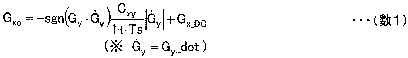
- Non-Patent Document 1 A command value for automatically performing acceleration / deceleration linked to the steering wheel operation is shown in Non-Patent Document 1, for example (Equation 1).
- the value obtained by multiplying the lateral jerk G y _dot by the gain C xy and adding the first order delay is used as the front / rear acceleration / deceleration control command G xc (which is the same as the target longitudinal acceleration / deceleration control command (G xt )). It is a control law. It has been confirmed in Non-Patent Document 2 that a part of the linkage control strategy of the expert driver's lateral and back-and-forth motion can be simulated.
- G x — DC in this equation is a deceleration component not linked to the lateral motion. This term is required when there is a foreseeable deceleration when there is a corner ahead or when there is a section speed command.
- the sgn (signum) term is a term provided so that the above operation can be obtained for both the right corner and the left corner. Specifically, the vehicle decelerates when turning in at the start of steering, and can stop when decelerating (because the lateral jerk becomes zero), and can perform an operation of accelerating when exiting the corner at the start of steering return.
- G the combined acceleration of longitudinal acceleration and lateral acceleration
- G-Vectoring control the acceleration of longitudinal acceleration and lateral acceleration
- Non-Patent Document 3 a skid prevention device for improving safety performance in the limit operation region is described in Non-Patent Document 3, in which the signs of ⁇ and ⁇ _dot are the same in the phase plane of the vehicle skid angle ⁇ and the vehicle skid angular velocity ( ⁇ _dot) It is reported that it is effective when used to make judgments for the start of skid prevention devices, because it is unstable (divergence direction) when the vehicle behavior transitions to a region far from the origin in the (III quadrant). .
- Non-Patent Documents 1 and 2 this control method is extracted from the brake and accelerator operations corresponding to the steering operation that is optionally performed by the expert driver.
- the simulation results show the mechanical rationality, maneuverability and stability improvement of this control method.
- This means that the acceleration / deceleration is controlled so that the behavior of the vehicle appropriately responds to the driver's steering operation, and as a result, it is possible to prevent the side slip angle of the vehicle from increasing. In particular, it is effective in reducing the so-called “understeer” in which the turning radius becomes too large for steering.
- this control does not compensate for reliably reducing the skid angle when the skid angle increases for some reason.
- the lateral acceleration becomes constant and the lateral jerk becomes zero.
- the acceleration / deceleration control command represented by (Equation 1) becomes zero, and the vehicle is in a stable state while drifting. Although it is stable mechanically, there is no guarantee that all drivers will be able to drive comfortably.
- skid prevention device described in Non-Patent Document 3 is operated based on the skid information, no skid is generated or a guideline for operation from a small daily area is not shown.
- side slip prevention device means that a moment is applied only after a large amount of side slip occurs. For this reason, control tends to be performed later, and a large moment is required to reduce understeer. As a result, the understeer reducing effect is reduced, and there is a concern that an uncomfortable feeling may be caused by unnecessarily slowing down.
- An object of the present invention is to provide a vehicle operation control device that can reliably reduce skid in the limit driving range, have less discomfort, and improve safety performance.
- the present invention provides a vehicle motion control apparatus capable of independently controlling the driving force and braking force of four wheels, based on a longitudinal acceleration / deceleration control command linked to the lateral motion of the vehicle.
- a vehicle motion control apparatus capable of independently controlling the driving force and braking force of four wheels, based on a longitudinal acceleration / deceleration control command linked to the lateral motion of the vehicle.
- the first mode for generating substantially the same driving force and braking force on the left and right wheels of the wheels, and the target yaw moment calculated from the side slip information of the vehicle.
- a second mode for generating a braking force and the first mode is selected when the target yaw moment is less than or equal to a predetermined threshold, and the second mode is selected when the target yaw moment is greater than the threshold. It is assumed that the configuration is selected.
- FIG. 1 is a diagram showing an overall configuration of a vehicle motion control device according to the present invention. It is a figure which shows lateral acceleration and lateral jerk estimation using the vehicle model of this invention. It is a figure which shows lateral acceleration and lateral jerk estimation using the acceleration sensor of this invention. It is a figure which shows the concept of the mutual complement by the estimation signal and measurement signal of this invention. It is a figure which shows the mode from the left corner approach of the G-Vectoring control vehicle of this invention to escape. It is a figure which shows the time series data in driving
- FIG. 1 shows the overall configuration of an embodiment of a vehicle motion control apparatus of the present invention.
- the vehicle 0 is constituted by a so-called by-wire system, and there is no mechanical coupling between the driver and the steering mechanism, the acceleration mechanism, and the deceleration mechanism.
- Vehicle 0 is a rear left wheel 63 by the motor 1, to drive the right rear wheel 64, the left front wheel 61 in the left front wheel motor 121, driving the right front wheel 62 at the right front wheel motor 122 four-wheel drive vehicle (A ll W heel D rive: an AWD vehicle).
- a driving force distribution mechanism 2 that is connected to the motor 1 and can freely distribute the torque of the motor to the left and right wheels is mounted.
- the present invention is not closely related to differences in power sources such as electric motors and internal combustion engines.
- the driving force and braking force of the four wheels can be freely controlled. The configuration will be described in detail below.
- the left front wheel 61, the right front wheel 62, the left rear wheel 63, and the right rear wheel 64 are each equipped with a brake rotor, a wheel speed detection rotor, and a wheel speed pickup on the vehicle side so that the wheel speed of each wheel can be detected. It has become.
- the depression amount of the accelerator pedal 10 of the driver is detected by the accelerator position sensor 31, and is processed by the central controller 40 which is a vehicle motion control device via the pedal controller 48.
- This calculation process includes torque distribution information corresponding to “slip prevention control” as an object of the present invention.
- the power train controller 46 controls the outputs of the motor 1, the left front wheel motor 121, and the right front wheel motor 122 according to this amount.
- the output of the motor 1 is distributed to the left rear wheel 63 and the right rear wheel 64 at an optimum ratio via the driving force distribution mechanism 2 controlled by the power train controller 46.
- Accelerator reaction force motor 51 is also connected to accelerator pedal 10, and reaction force is controlled by pedal controller 48 based on a calculation command from central controller 40.
- the central controller 40 which is a vehicle motion control device, is a vehicle motion control device that can independently control the driving force and braking force of the four wheels.
- Each of the left front wheel 61, the right front wheel 62, the left rear wheel 63, and the right rear wheel 64 is provided with a brake rotor, and a caliper that decelerates the wheel by sandwiching the brake rotor with a pad (not shown) on the vehicle body side. Is installed.
- the caliper is a hydraulic type or an electric type having an electric motor for each caliper.
- Each caliper is basically controlled by a brake controller 451 (for front wheels) and 452 (for rear wheels) based on a calculation command from the central controller 40.
- the brake reaction force motor 52 is also connected to the brake pedal 11, and the reaction force is controlled by the pedal controller 48 based on the calculation command of the central controller 40.
- the central controller 40 determines the integrated control command in an integrated manner, the brake controller 451 (for front wheels), 452 (for rear wheels), the powertrain controller 46, the motor 1, the driving force distribution mechanism 2 Is properly controlled through
- the steering system of the vehicle 0 has a steer-by-wire structure in which there is no mechanical connection between the steering angle of the driver and the tire turning angle.
- the power steering 7 includes a steering angle sensor (not shown), the steering 16, the driver steering angle sensor 33, and a steering controller 44.
- the steering amount of the driver's steering wheel 16 is detected by the driver steering angle sensor 33 and is processed by the central controller 40 via the steering controller 44.
- the steering controller 44 controls the power steering 7 according to this amount.
- Steer reaction force motor 53 is also connected to the steering wheel 16, and reaction force control is performed by the steering controller 44 based on a calculation command from the central controller 40.
- the amount of depression of the brake pedal 11 of the driver is detected by the brake pedal position sensor 32 and is processed by the central controller 40 via the pedal controller 48.
- the sensor for measuring the movement of the vehicle in this embodiment is equipped with an absolute vehicle speedometer, a yaw rate sensor, an acceleration sensor, and the like.
- vehicle speed and yaw rate are estimated by a wheel speed sensor, and yaw rate and lateral acceleration are estimated simultaneously using a vehicle speed, a steering angle, and a vehicle motion model.
- the vehicle 0 is mounted millimeter-wave ground vehicle velocity sensor 70, the speed V y of the longitudinal direction of the velocity V x and the lateral direction is independently detectable. Further, the wheel speeds of the respective wheels are inputted to the brake controllers 451 and 452 as described above.
- the absolute vehicle speed can be estimated by averaging the wheel speeds of the front wheels (non-drive wheels) from the wheel speeds of these four wheels. In the present invention, the method disclosed in Japanese Patent Laid-open No. Hei 5-16789 is used, and even when the wheel speed drops simultaneously at the four wheels by adding the signal of the acceleration sensor for detecting the wheel speed and the acceleration in the longitudinal direction of the vehicle.
- the absolute vehicle speed (V x ) is accurately measured.
- a configuration for estimating the yaw rate of the vehicle body by taking the difference between the left and right wheel speeds of the front wheels (non-driving wheels) is included, thereby improving the robustness of the sensing signal.
- the estimated absolute vehicle speed is compared and referred to the signal of the millimeter-wave to ground vehicle speed sensor 70, and is configured to complement each other when any of the signals is defective.
- the lateral acceleration sensor 21, the longitudinal acceleration sensor 22, and the yaw rate sensor 38 are disposed in the vicinity of the center of gravity. Differentiating circuits 23 and 24 are mounted for differentiating the outputs of the respective acceleration sensors to obtain jerk information. Further, a differentiation circuit 25 for differentiating the sensor output of the yaw rate sensor 38 to obtain a yaw angular acceleration signal is mounted.
- each sensor is installed in order to clarify the existence of the differentiation circuit.
- the acceleration signal is directly input to the central controller 40 to perform various arithmetic processes and then the differentiation process. May be. Therefore, the yaw angular acceleration of the vehicle body may be obtained by performing differentiation in the central controller 40 using the yaw rate estimated from the wheel speed sensor.
- an acceleration sensor and a differentiation circuit are used.
- the jerk sensor disclosed in Japanese Patent Application No. 2002-39435 may be used.
- a method of estimating the lateral acceleration and the lateral jerk is also employed.
- FIG. 2 describes a method of estimating the lateral acceleration estimated value G ye and lateral jerk estimate G ye _dot from the steering angle [delta].
- stability factor A and wheelbase l are parameters specific to the vehicle, and are fixed values obtained experimentally.
- the lateral acceleration G y of the vehicle can be expressed by the following equation (Equation 3) as the vehicle speed V, the lateral slip angle change speed ⁇ _dot of the vehicle, and the yaw rate r.
- ⁇ _dot is a motion within the linear range of the tire force and can be omitted as being small.
- the lateral acceleration G ye-wod is calculated by multiplying the yaw rate r with the dynamic characteristics omitted and the vehicle speed V.
- This lateral acceleration does not take into account the dynamic characteristics of a vehicle having response delay characteristics in the low frequency region. This is due to the following reason.
- the method of calculating the lateral acceleration and the lateral jerk using the steering angle has the advantages of suppressing the influence of noise and reducing the response delay between the lateral acceleration and the lateral jerk.
- this estimation method omits various vehicle slip information and ignores non-linear characteristics of tires. Therefore, when the skid angle increases, it measures the actual vehicle side acceleration and uses it. There is a need to do.
- FIG. 3 shows a method of obtaining lateral acceleration G ys and lateral jerk information G ys _dot for control using the detection signal G yso of the lateral acceleration sensor 21. Since noise components such as road surface unevenness are included, it is necessary to pass the sensor signal through a low-pass filter (time constant T lpfs ) (not dynamics compensation).
- the present embodiment employs a method of using both signals in a complementary manner as shown in FIG.
- the estimated signal (indicated by the subscript e as stimulated) and the detection signal (indicated by the subscript s as sensed) are multiplied by a variable gain based on the skid information (sideslip angle ⁇ , yaw rate r, etc.). Will be added together.
- variable gain K je (K je ⁇ 1) with respect to the lateral jerk estimation signal G ye —dot is changed to take a large value in a region where the side slip angle is small and to take a small value when the side slip increases.
- variable gain K js (K js ⁇ 1) with respect to the lateral jerk detection signal G ys —dot is changed to take a small value in a region where the side slip angle is small and to take a large value as the side slip increases.
- variable gain K ge (K ge ⁇ 1) for the lateral acceleration estimation signal G ye is changed to take a large value in a region where the side slip angle is small, and to take a small value when the side slip increases.
- variable gain K gs (K gs ⁇ 1) with respect to the lateral acceleration detection signal G ys is changed to take a small value in a region where the side slip angle is small and to take a large value as the side slip increases.
- Non-Patent Document 1 A guideline for acceleration / deceleration control linked to the lateral motion is disclosed in Non-Patent Document 1, for example.
- Non-Patent Document 2 a part of the linkage control strategy of the expert driver's lateral and back-and-forth motion can be simulated.
- G x — DC in ( Equation 1) is a deceleration component (acceleration / deceleration command that is automatically input based on the driver or external information) that is not linked to the lateral motion. This term is required when there is a foreseeable deceleration when there is a corner ahead or when there is a section speed command.
- the front / rear acceleration / deceleration control command G xc is the same as the target front / rear acceleration / deceleration control command G xt .
- the sgn (signum) term is a term provided so that the above operation can be obtained for both the right corner and the left corner.
- the vehicle decelerates when turning in at the start of steering, and can stop when decelerating (because the lateral jerk becomes zero), and can perform an operation of accelerating when exiting the corner at the start of steering return.
- Acceleration / deceleration according to lateral jerk can be understood as decelerating when lateral acceleration increases and accelerating when lateral acceleration decreases.
- the combined acceleration (represented as G) of longitudinal acceleration and lateral acceleration is a diagram in which the horizontal axis represents the longitudinal acceleration of the vehicle and the vertical axis represents the lateral acceleration of the vehicle.
- G-Vectoring control because it is directed to make a transition (Vectoring).
- FIG. 5 assumes a general traveling scene of entering and exiting a corner, such as a straight path A, a transition section B, a steady turning section C, a transition section D, and a straight section E. At this time, the acceleration / deceleration operation by the driver is not performed.
- FIG. 6 is a time calendar waveform for steering angle, lateral acceleration, lateral jerk, front / rear acceleration / deceleration control command calculated by (Equation 1), and braking and driving force of four wheels (61, 62, 63, 64).
- FIG. 6 As will be described in detail later, the front outer ring (62 when turning left), the front inner ring (61), the rear outer ring (64), and the rear inner ring (63) have the same value on the left and right (inner and outer). The braking force and driving force are distributed.
- the braking / driving force is a generic name for the force generated in the vehicle longitudinal direction of each wheel, the braking force is a force in the direction of decelerating the vehicle, and the driving force is defined as a force in the direction of accelerating the vehicle.
- the vehicle enters the corner from straight road section A.
- transient interval B point 1 to the point 3
- lateral acceleration G y of the vehicle increases.
- the lateral jerk G y _dot takes a positive value while the lateral acceleration in the vicinity of the point 2 is increasing (returns to zero at the time point 3 at which the lateral acceleration increase ends).
- the transient interval D points 5-7
- the lateral acceleration G y of the vehicle decreases by the switching-back operation of the steering of the driver.
- the lateral jerk G y _dot of the vehicle is negative
- the longitudinal acceleration / deceleration control command G xc is generated in the control vehicle from (Equation 1).
- substantially the same magnitude of driving force (+ sign) is applied to the front outer, front inner, rear outer, and rear inner wheels.
- the lateral jerk G y is 0 and the lateral jerk G y _dot is also zero, so acceleration / deceleration control is not performed.
- the vehicle decelerates from the turn-in at the start of steering (point 1) to the clipping point (point 3), stops during a steady circular turn (points 3 to 5), and starts steering return (points). Accelerate when exiting the corner from 5) (point 7).
- G-Vectoring control is applied to the vehicle, the driver can realize acceleration / deceleration motion linked to lateral motion only by steering for turning.
- this motion is expressed in a “gg” diagram that shows the acceleration mode generated in the vehicle, the longitudinal acceleration is plotted on the horizontal axis and the horizontal acceleration is plotted on the vertical axis, it is a characteristic motion that transitions into a smooth curved line.
- Become This means that the longitudinal acceleration / deceleration control command is determined so as to make a curved transition on the diagram with the passage of time.
- This curved transition left corner becomes a transition clockwise as shown in figure
- the right corner becomes a transition path obtained by inverting the G x-axis, the transition direction is counter-clockwise.
- the pitching motion generated in the vehicle by the longitudinal acceleration and the roll motion generated by the lateral acceleration are suitably linked, and the peak values of the roll rate and the pitch rate are reduced.
- FIG. 7 is a schematic diagram showing a situation in which a yaw moment in a direction (positive) that promotes turning is input from the counterclockwise turning standard state (A) of the vehicle 0.
- equations for the lateral motion and yawing (rotation) motion of the vehicle 0 in the standard state are shown below (Equation 4) and (Equation 5).
- m mass of the vehicle
- G y lateral acceleration applied to the vehicle
- F yf the lateral force of the front 2 wheels
- F yr lateral force of the rear two wheels
- M a yaw moment
- I z vehicle 0
- r_dot yaw angular acceleration of the vehicle 0 (r is yaw rate)
- l f distance between the center of gravity of the vehicle 0 and the front axle
- l r distance between the center of gravity of the vehicle 0 and the rear axle.
- (B) shows an example in which only the inner rear wheel (left rear wheel 63) is braked to give a braking force (F xrl ), and (C) in addition to this, the inner front wheel is braked and braking force is applied.
- (D) is an example in which driving forces (F xfr , F xrr ) are given to the outer front and rear wheels in addition to (C).
- the following yawing moment acts on the vehicle 0 (Equation 6).
- the force in the forward direction that is, the driving direction is positive
- the force in the braking direction is negative
- d indicates the distance (tread) between the left and right wheels.
- the combined braking / driving force of the left front and rear wheels is F xl
- the combined braking / driving force of the right front and rear wheels is F xr .
- FIG. 8 shows a distribution of braking / driving force that generates a negative moment, that is, a yaw moment in a negative direction, that is, a clockwise (restoring side) yaw when turning left. Also in this case, the equation of yawing motion is (Expression 6).
- the longitudinal acceleration G x and the lateral acceleration G y of the measured vehicle, positive direction of the vehicle acceleration in a lateral axis, in the negative direction takes deceleration, left of the vehicle in the positive direction of the longitudinal axis
- the target yaw moment M t is a clockwise value when viewed from the top of the vehicle in the diagram showing the lateral acceleration in the direction and the right acceleration in the negative direction
- the left wheel has a greater deceleration than the right wheel.
- the right wheel is given a greater driving force than the left wheel, and when the target yaw moment M t is counterclockwise when viewed from above the vehicle, the right wheel is given a greater deceleration than the left wheel Suppose that the left wheel is given a greater driving force than the right wheel.
- the measured longitudinal acceleration G x and lateral acceleration G y of the vehicle are obtained by taking the acceleration of the vehicle in the positive direction of the horizontal axis and the deceleration in the negative direction, and in the left direction of the vehicle in the positive direction of the vertical axis.
- acceleration in the right direction in the negative direction when starting counterclockwise movement when viewed from above the vehicle, it shows a clockwise curvilinear transition over time
- acceleration / deceleration in the front-rear direction is determined according to lateral motion so as to show a counterclockwise curvilinear transition as time passes.
- FIG. 9 shows a case where “understeer” and “oversteer” are as follows for the traveling scenes of entry into and exit from a corner, such as a straight path A, a transition section B, a steady turning section C, a transition section D, and a straight section E.
- the result of performing the “slip prevention control” in a situation where the vehicle slips and the vehicle deviates from the course is shown.
- FIG. 10 shows a steering angle, a yaw rate including an estimated value, an estimated vehicle side slip angle, a yaw moment command obtained therefrom, and braking of four wheels (61, 62, 63, 64), which are used for the intervention condition of the “slip prevention control”.
- Driving force, vehicle longitudinal acceleration and lateral acceleration at this time are shown as time calendar waveforms.
- the yaw rate r ⁇ obtained from the steering is calculated using (Equation 2) using the stability factor A, the wheel base 1, the vehicle speed V, and the steering angle ⁇ . Since the steering angle of the driver is used as an input, it can be considered that the intention of the driver is reflected best.
- the yaw rate r Gy obtained from the lateral acceleration is obtained by omitting the side slip angle change ⁇ _dot and dividing the lateral acceleration by the vehicle speed as in (Equation 7) as in (Equation 3). Is.
- This value is considered to indicate the revolution speed of the vehicle, and is considered to be an amount indicating the vehicle turning limit.
- the yaw rate r s detected by the yaw rate sensor 38 indicates the actual rotation speed of the vehicle.
- the skid angle ⁇ is defined as the arc tangent arctan (v / u) obtained by using the vehicle speed u in the longitudinal direction and the vehicle speed v in the lateral direction.
- the arrow passing through the center of gravity of the vehicle in FIGS. 7 and 8 indicates the vehicle traveling direction, the angle formed by this and the longitudinal direction of the vehicle is the side slip angle, and the vehicle fixed coordinate system counterclockwise is positive.
- FIG. 7 shows a state in which oversteer ⁇ spin is induced when the side slip angle is negative and large.
- FIG. 8 shows a state in which understeer ⁇ path protrusion is induced in a state where the side slip angle is positive and large.
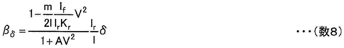
- the side slip angle ⁇ ⁇ obtained from the steering can be calculated as follows using the vehicle motion model.
- m vehicle mass, K r is a cornering stiffness representing the gain of the lateral force per unit side slip angle of the rear wheels.
- the side slip angle is detected by the millimeter-wave-to-ground vehicle speed sensor 70 independently of the longitudinal velocity V x and the lateral velocity V y , and may be obtained by the following (Equation 9) or as (Equation 10).
- An integration method may be used.
- ⁇ a method similar to that disclosed in Japanese Patent Laid-Open No. 09-315277 is used to determine (1) the “side slip prevention control” intervention condition and (2) the yaw moment control amount.
- Intervention conditions The yaw rate obtained from the lateral acceleration is compared with the actual yaw rate. When the actual yaw rate is small, it is determined that the vehicle is understeer, when it is large, it is oversteered. The The threshold value, dead zone, and the like at this time are adjusted by a sensitivity test such as a test driver.
- Yaw moment control amount Basically, the yaw moment is added so that the actual value is close to the yaw rate obtained from the steering and the side slip angle. Further, the side slip angle differential value or the like is multiplied by a gain adjusted to fit the feeling, and correction is performed using a value obtained by adding these.
- the equivalent cornering stiffness of the rear wheels is relatively lowered in the maximum lateral acceleration state, and it is likely that oversteer will occur to induce spin. This can be detected because the actual yaw rate r s is larger than the yaw rate r Gy obtained from the lateral acceleration, and the side slip angle is larger than the threshold value ⁇ th , resulting in a large side slip angle. It can be detected from being.
- braking force is generated on both the right (outer) front wheel and the rear wheel, and a clockwise moment is applied. Due to this braking force, as shown in the longitudinal acceleration (second from the bottom) in FIG. 10, the deceleration of the profile similar to the sum of the braking forces of the front outer wheel and the rear outer wheel acts.
- the front outer ring (62 when turning left), the front inner ring (61), the rear outer ring (64) and the rear inner ring (63) have different values on the left and right (inner and outer).
- the braking force is distributed so that
- the present invention addresses such problems by automatically performing acceleration / deceleration linked to the steering operation operated from the daily operation range (G-Vectoring), and reliably reducing the side slip in the limit operation range (side slip prevention control). By fusing together, there is little sense of incongruity and safety performance can be improved.
- G-Vectoring acceleration / deceleration linked to the steering operation operated from the daily operation range
- side slip prevention control side slip prevention control
- FIG. 11 schematically shows the relation between the arithmetic control logic of the central controller 40 and the observer that estimates the skid angle based on signals from the vehicle 0, the sensor group, and the sensors (although calculation is performed in the central controller 40). It is shown in.
- the entire logic is roughly composed of a vehicle lateral motion model 401, a G-Vectoring controller unit 402, a yaw moment controller unit 403, and a braking force / driving force distribution unit 404.
- the vehicle lateral motion model 401 uses the steering angle ⁇ input from the driver steering angle sensor 33 and the vehicle speed V to calculate the estimated lateral acceleration (G ye ), target, using ( Equation 2), (Equation 3), or (Equation 8).
- the yaw rate r t and the target skid angle ⁇ t are estimated.
- the target yaw rate r t is set to be the same as the yaw rate r ⁇ obtained from the steering described above.
- the logic 410 is a logic that calculates a lateral acceleration and a lateral jerk based on the estimated lateral acceleration (G ye ) estimated and the actual lateral acceleration actually measured.
- the G-Vectoring controller 402 uses these lateral acceleration and lateral jerk to determine the component linked to the current vehicle lateral motion in the target longitudinal acceleration / deceleration control command G Xt according to (Equation 1). Furthermore, a target longitudinal acceleration / deceleration control command G Xt is calculated by adding G x — DC which is a deceleration component not linked to the current lateral vehicle motion, and is output to the braking force / driving force distribution unit 404.
- G x_DC is a term that is necessary when there is a predictive deceleration when there is a corner ahead or when there is a section speed command. Since the section speed command is information determined by the coordinates at which the vehicle is present, it can be determined by checking the coordinate data obtained by GPS or the like against the map information on which the section speed command is posted. . Next, foreseeable deceleration with respect to the front corner, although details of detection are omitted in the present embodiment, for example, a camera such as a monocular camera, a stereo camera, a ranging radar such as a laser and a millimeter wave, or GPS information, etc.
- the target yaw rate r t (r ⁇ ), the target skid angle ⁇ t , the actual yaw rate, and the actual (estimated) according to the logic described above.
- a target yaw moment M t is calculated based on the deviations ⁇ r and ⁇ from the sideslip angle and output to the braking force / driving force distribution unit 404.
- the braking force / driving force distribution unit 404 determines the braking / driving forces (F xfl , F xfr , F xrl , F xrr) of the four wheels of the vehicle 0 based on the target longitudinal acceleration / deceleration control command G Xt or the target yaw moment M t. ).
- the target longitudinal acceleration / deceleration control command G Xt or the target yaw moment M t. shows a basic distribution law, which in addition to the characteristic in the "G-Vectoring" control in the present invention, indirect yaw moment control: for (IYC I ndirect Y aw-moment C ontrol) effect
- Equation 11 Equation 12
- Equation 13 Equation 14
- the front / rear acceleration / deceleration control command by “G-Vectoring” control and the moment command by “slip prevention control” can be made compatible. ⁇
- the driving force could be distributed.
- these are distributed to the front and rear wheels according to the vertical load ratio of the front and rear wheels. Assuming that the height of the sprung center of gravity of the vehicle 0 from the ground is h, and the vehicle 0 is accelerating and decelerating with the target longitudinal acceleration / deceleration control command G xt , the load for the two wheels of the front wheel and the rear wheel ( W f , W r ) are as follows (Equation 21) and (Equation 22), respectively.
- Equation 28 The details of (Equation 28) are calculated using a method similar to that disclosed in Japanese Patent Laid-Open No. 09-315277.
- the central controller 40 which is a vehicle motion control device of the present invention, it is necessary to fuse and decouple the “G-Vectoring control” that works from the daily range and the “side slip prevention device” that works in the limit range.
- yawing motion Considering vehicle motion as motion on a plane, it can be described by (1) back-and-forth motion, (2) lateral motion, and rotation around the center of gravity, that is, (3) yawing motion.
- “G-Vectoring control” that realizes acceleration / deceleration linked to lateral movement is (1) controlling acceleration / deceleration in the front-rear direction, and (3) not directly controlling yawing moment.
- the yawing moment is “arbitrary” and has a degree of freedom.
- the “side skid prevention device” directly controls (3) the yaw moment, not (1) acceleration / deceleration. That is, the longitudinal acceleration / deceleration is “arbitrary” and has a degree of freedom.
- the longitudinal acceleration is controlled according to the acceleration / deceleration control command linked to the lateral motion determined by the “G-Vectoring control”, and the “skid prevention control device” is determined.
- the yawing moment may be controlled in accordance with the yaw moment command to be performed.
- the device is configured to have the following two modes.
- the commanded acceleration / deceleration can be realized while maintaining the commanded yawing moment (the fusion of the two controls and the non-interference).
- the first mode (G) generates substantially the same driving force and braking force on the left and right wheels of the four wheels based on the longitudinal acceleration / deceleration control command G xc linked to the lateral movement of the vehicle. -Vectoring control) and different driving force and control for the left and right wheels of the four wheels based on the target yaw moment M t calculated from the side slip information of the vehicle (steer angle ⁇ , vehicle speed V, yaw rate r, side slip angle ⁇ ).
- a second mode for generating power (side slip prevention control), and when the target yaw moment M t is less than or equal to a predetermined threshold value M th, the first mode is selected and the target yaw moment is less than the threshold value.
- a desired driving force may not be generated.
- “side skid prevention control” is given priority, and a moment is surely generated to ensure safety.
- the tire lateral force is proportional to the tire side slip angle when the side slip angle is small, and has a saturation characteristic when it is large. Since it is assumed that the loads on the front and rear wheels are equal, the same lateral force is generated for the same side slip angle.
- the front wheel load increases as shown in ( Expression 21), and the rear wheel load decreases as shown in (Expression 22).
- the lateral force F yf of the front wheels increases and the lateral force F yr of the rear wheels decreases. If this phenomenon is considered based on the yawing equation of motion of (Equation 17), a moment that promotes turning will work. Further, if the vehicle accelerates during turning, the restoring side yaw moment acts as shown in the lower part of FIG.
- the lateral acceleration increases, that is, the vehicle decelerates when starting a turn, and therefore the yaw moment in the direction of promoting the turn works. Further, when the lateral acceleration decreases, that is, when the turn is finished, the acceleration is performed, so that the yaw moment in the direction toward restoring the turn and going straight goes on.
- Step (1) the vehicle speed V, the yaw rate r, the lateral acceleration G y, lateral jerk G y _dot, sideslip angle beta, the slip angular velocity ⁇ _dot detected or estimated (Step (1)), linked to the lateral motion based on the G-Vectoring control law
- the target longitudinal acceleration / deceleration control command G xt is calculated (step (2)).
- (1) intervention conditions and (2) a control amount, that is, a target yaw moment M t is calculated so as to reduce the side slip of the vehicle (step (3)).
- some explanation is added about the target yaw moment M t .
- a cornering force approximately proportional to the cornering stiffness (unit N / rad) representing the lateral stiffness of the tire is generated.
- the cornering force generated by the front wheels and the turn acceleration side yaw moment expressed by the product of the distance from the vehicle center of gravity to the front axle, and the cornering force generated by the rear wheels and the turn expressed by the distance from the vehicle center of gravity to the rear axle
- the combined moment of the yaw moment on the stop side is the restored yaw moment that naturally occurs in the vehicle when a side slip occurs.
- the target yaw moment command is less than or equal to the restored yaw moment, it naturally converges to a state of small skid without intentionally adding yaw moment control. If the control is applied in such a state, it gives an impression of excessive control as a driver feeling. In order to avoid such a phenomenon, the yaw moment control is not performed below a threshold value that is a restored yaw moment unique to the vehicle. In the current skid prevention device, a test drive is repeatedly performed by a test driver, and this dead zone is set based on feeling evaluation.
- the target yaw moment command M t obtained in step (3) indicates a specific control command value in a situation where control is required as a value equal to or greater than the dead zone (a value obtained simply from skid information). However, if it is below the dead zone, M t is zero).
- This yaw moment command is a basic yaw moment command when acceleration / deceleration is not performed.
- step (4) it is determined whether or not there is a longitudinal acceleration / deceleration control command.
- step (5) the control law is switched based on the magnitude of the target yaw moment M t .
- the target yaw moment M t is compared with a preset threshold value M th to determine whether yaw moment control is performed so that the braking and driving forces of the left and right wheels are separately distributed ((7) to (10). )), It is determined whether to perform only G-Vectoring that distributes substantially equal braking and driving force between the left and right wheels (5).
- the restoration yaw moment for determining the dead zone can be roughly set from the tire characteristics and vehicle specifications.
- the tire characteristics have load dependency as described in the explanation of FIG.
- the restored yaw moment changes in an equivalent manner and the required amount of yaw moment control is further reduced.
- step (6) compared with the absolute value of the basic yaw moment command M t determined in step (3), when M t is equal to or less than M th , acceleration / deceleration control with equal distribution of left and right wheels by G-Vectoring control is performed. It is the structure to perform (step (6)).
- the G-Vectoring control when the G-Vectoring control is operating as shown in FIG. 14, the left / right distribution of the braking force / driving force is not performed unless the yaw moment control amount exceeds a certain threshold. It is configured to include such logic.
- the first mode G-Vectoring (step (6))
- the second mode side slip prevention control (step ( 7) to (10)).
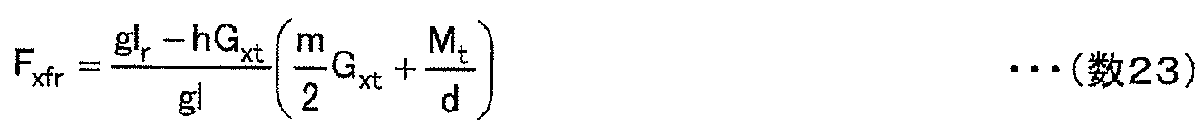
- the vehicle longitudinal acceleration realized in the second mode that generates different braking / driving forces on the left and right wheels of the four wheels is different from the (G-Vectoring) longitudinal acceleration / deceleration control command. Is corrected so that substantially equal braking / driving force is applied to the left and right wheels of the four wheels (see also step (9) (Equation 23) to (Equation 26)).
- the left and right of the four wheels are not necessarily
- the vehicle longitudinal acceleration realized in the second mode (side slip prevention control) that generates different braking / driving forces on the wheels does not coincide with the longitudinal acceleration / deceleration control command in (G-Vectoring).
- step (10) if brake control is performed when the G-Vectoring command is zero, deceleration will inevitably occur (step (10)).
- the G-Vectoring control command is larger than the deceleration generated by the skid prevention control command, the braking / driving is substantially equal to the left and right wheels of the four wheels so that the difference from the G-Vectoring control command is close.
- Correction control can be performed so as to apply force, and there are scenes that solve the problems of the present invention, and are within the scope of the present invention.
- the present invention determines target longitudinal deceleration control command G xt is whether zero, if target longitudinal deceleration control command G xt is not zero, and the threshold target yaw moment M t is predetermined M
- the braking / driving force distribution unit 404 determines the braking driving force (F xfl , F xfr , F xrl , F xrr ) of each wheel of the vehicle based on the target longitudinal acceleration / deceleration control command G xt
- the brake driving force is calculated so as to be distributed approximately equally.
- target longitudinal deceleration control command G xt is whether zero, if target longitudinal deceleration control command G xt is zero, or if the target longitudinal acceleration or deceleration control command G xt is not 0, and
- the braking force / driving force distribution unit 404 uses the braking yaw moment (F xfl , F xfr , F xrl) of each wheel of the vehicle based on the target yaw moment M t. , F xrr ) are calculated so as to distribute the braking driving force of the left and right wheels separately.
- FIGS. 15, 16, and 17 are examples in which the present invention is applied to scenes to which only the “slip prevention control” shown in FIGS. 9 and 10 is applied. Further, FIG. 16 assumes the case where “under steer” and “over steer” occur at the same point as in FIGS. 10 and 15, but with a slight change in the steer characteristic.
- FIG. 15 shows the longitudinal acceleration / deceleration control command, yaw moment control command, wheel braking / drive distribution determined according to the lateral motion generated according to the steering angle, vehicle yaw moment, vehicle longitudinal acceleration realized thereby, The vehicle lateral acceleration is shown.
- the dotted line is the front / rear acceleration / deceleration control command for only “G-Vectoring” control
- the broken line is the deceleration amount based on the yaw moment command for “side slip prevention control”.
- the longitudinal acceleration follows the command of the “G-Vectoring” control, and the yaw moment required by the “slip prevention control” You can see that it has been realized. Further, at points 4 to 5, the braking force of the front outer wheel and the rear outer wheel is reduced, the driving force is given to the front inner wheel and the rear inner wheel, and the vehicle longitudinal acceleration is controlled by the command of the “G-Vectoring” control. It can be seen that the vehicle is following the command of “slip prevention control”.
- a yaw moment command for reducing understeer is generated from points 2 to 3, but the longitudinal acceleration / deceleration control command is Since the yaw moment command is smaller than the threshold value M th in a certain state, the left and right wheel independent braking / driving control is omitted (the same braking force for the left and right wheels, step (6) in FIG. 14).
- the yaw moment command is smaller than the threshold value M th , but there is no front-rear acceleration / deceleration control command by “G-Vectoring”, and load movement does not occur on the front and rear wheels.
- the actual longitudinal acceleration Gx is measured by the longitudinal acceleration sensor 22, and multiplied by the gain K1 or differentiated to obtain the longitudinal jerk, the value multiplied by the gain K2 and the target longitudinal acceleration / deceleration. It is only necessary to compare the control command G xt and determine the braking force, driving force F xff and F xrr based on the deviation ⁇ G x .
- “S” of K2s is a Laplace operator, and a differential value is slightly fed back to improve responsiveness.
- the gain K2 is intended to improve control responsiveness and is not an essential configuration.
- the actual acceleration of the vehicle may be measured by using a differential value of the wheel speed or the like to estimate the inclination.
- the actual longitudinal acceleration can be made to follow the target longitudinal acceleration regardless of disturbances such as tilt, and control deterioration can be reduced.
- the threshold value is used, and the longitudinal acceleration command below the threshold value is configured not to perform control and to reduce the jerky feeling.
- a threshold value is provided for the absolute value of the longitudinal acceleration control command.
- a low-pass filter that passes only the frequency of the lateral motion of the vehicle (at most 2 Hz) is passed.
- Actual actuator control may be performed based on the vehicle longitudinal acceleration command. As a result, the jerky feeling in the front-rear direction can be reduced even when the road surface is uneven.
- the lateral acceleration which is an estimated value using a vehicle model for the steering angle as shown in FIG.
- a difference in amplitude and a phase occur between the lateral jerk, the lateral acceleration actually measured by the lateral acceleration sensor 21, and the lateral jerk obtained by time differentiation.
- the measured value is delayed with respect to the model estimated value.
- the lateral movement is performed using (Equation 1). A linked vehicle longitudinal acceleration command was formed.
- the target front / rear acceleration / deceleration control command G xt includes a plurality of modes having different calculation methods depending on the traveling road surface, and switching means for switching the plurality of modes.
- control mode can be switched by a driver with a control selector 81 (switching means) installed in the passenger compartment.
- AUTOMATIC automatically switches modes, and in accordance with changes in road surface conditions such as the friction coefficient, the gains of linear combination, select high, lateral jerk due to model estimates, and lateral jerk due to measured values Configured to adjust. For example, braking force and driving force control is performed in accordance with the longitudinal acceleration command, the actual longitudinal acceleration is detected, and if the actual longitudinal acceleration is significantly smaller than the command value, select high control is performed assuming that the friction coefficient is small. It is configured to improve the feeling of feeling by automatically selecting or increasing the gain of jerk on the model estimated value side.
- These mode switching and gain switching may be in a map format corresponding to the estimated friction coefficient. Accordingly, it is possible to automatically obtain a longitudinal acceleration / deceleration control command linked to a suitable lateral movement according to the road surface condition. Furthermore, although detailed description is omitted in the present embodiment, the AUTOMATIC mode is further subdivided, and the model estimated jerk gain is increased so that the model moves sharply with respect to steering. Comfort mode, etc. that can increase the acceleration gain and realize a relaxed movement may be set. Moreover, you may switch a gain and a mode as emergency avoidance mode by taking in external information.
- modes other than AUTOMATIC are modes that the driver can select arbitrarily.
- TARMAC is assumed to be used mainly for traveling on dry pavement, and jerk linear combination mode is used. Since the responsiveness of the vehicle motion to the steering is high, the model estimated lateral jerk and the lateral jerk by the measurement value are almost the same value. Further, the gain of the model estimated lateral jerk and the gain of the lateral jerk based on the measured value are substantially the same.
- GRAVEL is assumed to be used mainly for traveling on wet roads and dirt roads, and the control threshold shown in FIG. 21 is set to be slightly larger. Further, although the linear combination mode is adopted, the gain of the model estimated lateral jerk is slightly larger than the gain of the lateral jerk based on the measured value, so that the steering is improved.
- SNOW is assumed to be mainly used for running on snowy roads, and the control threshold shown in FIG. 21 is set to be slightly larger than GRAVEL.
- select high control is adopted.
- the model estimated lateral jerk gain is larger than the lateral jerk gain measured. This ensures good steering and continuity of motion for lateral motion with delayed response.
- the change in the vehicle response accompanying the change in the road surface condition has a great influence on the driving operation of the driver, and the vehicle movement itself also changes greatly. It is important to perform an appropriate driving operation with respect to the vehicle response that changes from time to time.
- the control state and the motion state of the vehicle are displayed on the multi-information display 82 in the passenger compartment, thereby supporting the driver's precise driving operation.
- the display mode shows the current vehicle motion state by showing the “gg” diagram with the vehicle's longitudinal acceleration on the horizontal axis and the vehicle's lateral acceleration on the vertical axis, and time-series data of acceleration. It has a plurality of modes for displaying reference information for determining driving operations.
- tire braking / driving force or generated yaw moment is displayed to clarify the control state, and whether the current vehicle is in the “G-Vectoring control state” or “DYC state” Is displayed.
- This is intended to clarify the control effect on the currently occurring vehicle motion and to make the driver perform the vehicle driving operation more accurately.
- “G-Vectoring control” imitates “acceleration / deceleration operation linked to lateral movement” performed by an expert driver, and does not independently control braking / driving force of four wheels. For this reason, if the driver can perform an equivalent acceleration / deceleration operation, there is a possibility that an equivalent movement can be realized without the system side actively controlling. It is considered that the driver is more likely to be able to perform “G-Vectoring control” himself / herself by experiencing his / her driving operation and the accompanying vehicle motion, and by viewing the control state on the multi-information display 82.
- the conventional skid prevention device controls the left and right braking force or driving force after the skid occurs.
- emergency avoidance to avoid obstacles ahead, the driver performs a sudden steering operation.When understeer occurs, the driver must apply left and right braking forces to wait for understeer and generate a moment to counteract understeer. Will be added. That is, during the occurrence of understeering ⁇ detection, the vehicle is in a no-brake state and the vehicle approaches an obstacle.
- the present invention since the braking force is generated from the moment when the driver starts steering, the relative speed with respect to the obstacle can obviously be reduced, and the emergency avoidance performance can be greatly improved.
- the absolute value of the initial steering angle for avoidance becomes smaller, and the return steering after avoidance can be reduced. For this reason, a stable avoidance operation can be realized without making the vehicle response self-vibrating due to a delay in the steering response (this can provide a similar effect even when turning a sharp curve).
Abstract
Description
M. Yamakado, M. Abe: Improvement of Vehicle Agility and Stability by G-Vectoring Control, Proc. of AVEC2008-080420. M. Yamakado, M. Abe: Proposal of the longitudinal driver model in coordination with vehicle lateral motion based upon jerk information, Review of Automotive Engineering, Vol.29.No.4.October 2008,P.533~541. S. Inagaki, I. Kushiro, M. Yamamoto: Analysis on Vehicle Stability in Critical Cornering Using Phase-Plane Method, Proc. of AVEC1994- 9438411
1 モータ
2 駆動力配分機構
7 パワーステアリング
10 アクセルペダル
11 ブレーキペダル
16 ステアリング
21 横加速度センサ
22 前後加速度センサ
23,24,25 微分回路
31 アクセルセンサ
32 ブレーキセンサ
33 舵角センサ
38 ヨーレイトセンサ
40 中央コントローラ
44 ステアリングコントローラ
46 パワートレインコントローラ
48 ペダルコントローラ
51 アクセル反力モータ
52 ブレーキ反力モータ
53 ステアリング反力モータ
61 左前輪
62 右前輪
63 左後輪
64 右後輪
70 ミリ波対地車速センサ
81 制御セレクター
82 マルチインフォメーションディスプレイ
121 左前輪モータ
122 右前輪モータ
451,452 ブレーキコントローラ
車両0はモータ1により左後輪63、右後輪64を駆動するとともに、左前輪モータ121で左前輪61を、右前輪モータ122で右前輪62を駆動する四輪駆動車(All Wheel Drive:AWD車)である。モータ1に連接して、モータのトルクを左右輪に自由に配分することが可能な駆動力配分機構2が装着されている。ここで、特に電気モータや内燃機関などの動力源の差異については、本発明に密接な関係は無い。本発明を示す、最も好適な例として、また、あとで示す四輪独立ブレーキと組み合わせることにより、四輪の駆動力および制動力を自由に制御できるような構成となっている。以下、詳細に構成を示していく。
左前輪61,右前輪62,左後輪63,右後輪64には、それぞれブレーキロータが配備され、車体側にはこのブレーキロータをパッド(図示せず)で挟み込むことにより車輪を減速させるキャリパーが搭載されている。キャリパーは油圧式、あるいはキャリパー毎に電機モータを有する電機式である。
本発明においては、横滑り角情報に基づいて左右輪に異なる制動力や駆動力を発生させることになるが、ヨーモーメントとして寄与するのは左右の制動力あるいは駆動力の差分である。したがってこの差分を実現するために片側は駆動して、反対側を制動するなどの通常とは異なる動作もありうる。このような状況での統合制御指令は中央コントローラ40が統合的に指令を決定し、ブレーキコントローラ451(前輪用),452(後輪用),パワートレインコントローラ46,モータ1,駆動力配分機構2を介して適切に制御される。
車両0の操舵系はドライバの舵角とタイヤ切れ角の間に機械的な結合の無い、ステアバイワイヤ構造となっている。内部に舵角センサ(図示せず)を含むパワーステアリング7とステアリング16とドライバ舵角センサ33とステアリングコントローラ44で構成されている。ドライバのステアリング16の操舵量は、ドライバ舵角センサ33により検出され、ステアリングコントローラ44を経て、中央コントローラ40で演算処理される。そしてステアリングコントローラ44はこの量に応じて、パワーステアリング7を制御する。
つぎに本発明の運動センサ群について述べる。本実施例における車両の運動を計測するセンサについては、絶対車速計,ヨーレイトセンサ,加速度センサなどを搭載している。これに加え、車速,ヨーレイトについては車輪速センサによる推定,ヨーレイト,横加速度については、車速と操舵角と車両運動モデルを用いた推定などを同時に行っている。


横運動に連係した加減速制御の指針は、例えば非特許文献1に示されている。
つぎに、左右輪駆動・制動力配分によるヨーモーメント制御について図面を用いて簡単に示す。図7は車両0の反時計回りの旋回標準状態(A)から旋回を促進する方向(正)のヨーモーメントを入力した状況を示す模式図である。まず、標準状態での車両0の横方向の運動方程式とヨーイング(回転)運動の方程式を以下(数4)(数5)に示す。


横加速度から求めたヨーレイトと実ヨーレイトを比較して、実ヨーレイトが小さいときは、アンダーステア、大きいときはオーバーステア、さらに横滑り角が負で大きい場合はオーバーステアであると判断される。このときの閾値、不感帯などは、テストドライバなどの感応試験により調整される。
基本的には操舵から求めたヨーレイトと、横滑り角に実際の値が近くなるようにヨーモーメントを加える。さらには横滑り角微分値などにフィーリングに合うように調整されたゲインを掛け合わせ、これらを足し合わせた値を用いて補正を行っている。
図11は、中央コントローラ40の演算制御ロジックと、車両0、センサ群およびセンサからの信号をもとに(中央コントローラ40内で演算するのであるが)横滑り角を推定するオブザーバーの関係を模式的に示したものである。ロジック全体はおおまかに、車両横運動モデル401,G-Vectoringコントローラ部402,ヨーモーメントコントローラ部403,制動力・駆動力配分部404にて構成されている。


(2)路面凹凸入力による横加速度に起因する加減速制御のギクシャク感
(3)路面性状変化による操舵応答の変化
それぞれについて、課題を明確化し、本発明における解決方法について開示していく。
車両重量をMとすると、図19に示すように、傾斜θの角度を有するスロープを降りている際に、車両には、Mg・sinθの重力成分が前後に加わる。前後加減速制御指令Gxcに対し、オープンループでブレーキ液圧制御、あるいはモータトルク制御等を行って前輪前後力Fxff,後輪前後力Fxrrを制御していると、減速指令値に対し、実際の車両減速度はGx=Gxc-Mg・sinθとなってしまい、目標どおりの制御を行うことができなくなる。これに対し、図20に示すように実前後加速度Gxを前後加速度センサ22で計測し、それにゲインK1を掛ける、あるいは微分して前後加加速度を求め、ゲインK2を掛けた値と目標前後加減速制御指令Gxtとを比較してその偏差ΔGxにもとづいて制動力,駆動力Fxff,Fxrrを決定すれば良い。K2sの“s”はラプラス演算子であり、応答性改善のために、若干微分値をフィードバックしているものである。
さらに前後加速度センサ22を搭載しないようなシステムを考える場合、車輪速の微分値を用いるなどして、車両の実加速度を計測し、傾斜推定を行っても良い。
図21に示すように路面がフラットではなく、路肩部分が凍結した雪に覆われていたりした場合、凹凸路に乗り上げたときには路肩側のタイヤは絶えず路面から加振され、ドライバの舵角に細かいキックバックトルクを発生させ、舵角変化Δδが発生する。また、小刻みなロールが発生して重心点に横加速度変化ΔGyが発生し、結果として横加加速度にノイズが発生する。このような状況で図4に示すような方法のみをとっていると、図に示すように、前後加速度に細かな高周波成分が発生することになる。このような状況を避けるために、本発明においては閾値を用いて、閾値以下の前後加速度指令については、制御を行わないようにしてギクシャク感を低減するような構成となっている。また、本実施例では前後加速度制御指令の絶対値に閾値を設けているが、周波数に閾値を用いるような考えとして、車両の横運動の周波数(高々2Hz)のみを通過させるローパスフィルターを通した車両前後加速度指令に基づいて実際のアクチュエータ制御を行っても良い。これにより路面凹凸があるような場合でも前後方向のギクシャク感を低減することができる。
図22に示すように雪面などで、路面摩擦状況が変化すると、図2に示したような操舵角に対する車両モデルを用いた推定値である横加速度,横加加速度と、実際横加速度センサ21で計測された横加速度、それを時間微分して得られた横加加速度の間に、振幅の違いおよび位相の違いが発生する。低摩擦領域においては、計測値がモデル推定値に対して遅れ気味になる。先の実施例においては、図に示すように、モデル推定値による横加加速度と、計測値による横加加速度にゲインを乗じて足し合わせた線形結合値に基づいて(数1)を用いて横運動に連係した車両前後加速度指令を形成していた。このように構成された車両において圧雪路を走行した場合、操舵を開始した瞬間の手ごたえ感、回頭性が低下するとともに、実際の横加速度がまだ増加している状態で減速度が低下してしまい、ロール運動とピッチ運動の連続性が希薄となってしまう。このような状況では操舵操作に対して応答遅れの少ないモデル推定値による横加加速度と、実際の車両の横運動と連係が取れた計測値である横加加速度のどちらか振幅の大きいほうを選ぶ、いわゆるセレクトハイで得られる信号に基づいて(数1)を用い、前後加速度を選ぶことにより、手ごたえ感と運動の連続感を両立することができる。また、セレクトハイで得られた制御指令をローパスフィルターに通すことにより平滑化することにより、さらに運動の連続感を向上させることができる。
Claims (17)
- 四輪の駆動力と制動力を独立に制御可能な車両の運動制御装置において、
前記車両の横運動に連係した目標前後加減速制御指令に基づいて、前記四輪のうちの左右輪に略同一の駆動力及び制動力を発生する第1のモードと、前記車両の横滑り情報から算出した目標ヨーモーメントに基づいて、前記四輪のうちの左右輪に異なる駆動力及び制動力を発生する第2のモードと、を有し、
前記目標ヨーモーメントが予め定めた閾値以下のときは前記第1のモードが選択され、前記目標ヨーモーメントが前記閾値よりも大きいときは第2のモードが選択される車両の運動制御装置。 - 請求項1記載の車両の運動制御装置において、
入力された舵角δと、車速Vに基づいて推定横加速度,目標ヨーレイト,目標横滑り角を推定する車両横運動モデルと、
前記推定横加速度と実横加速度に基づいて算出された横加速度と横加加速度に基づいて前記目標前後加減速制御指令を算出する第1の処理部と、
前記目標ヨーレイトと入力された実ヨーレイトとの偏差と、前記目標横滑り角と入力された実横滑り角との偏差と、に基づいて目標ヨーモーメントを算出する第2の処理部と、
前記目標前後加減速制御指令又は前記目標ヨーモーメントに基づいて車両の各輪の制動駆動力を算出する制動力駆動力配分部と、を有する車両の運動制御装置。 - 請求項2記載の車両の運動制御装置において、
前記目標前後加減速制御指令が0か否かを判断し、前記目標前後加減速制御指令が0ではない場合、且つ前記目標ヨーモーメントが予め定めた閾値以下の場合、前記制動力駆動力配分部で前記目標前後加減速制御指令に基づいて車両の各輪の制動駆動力を左右輪の制動駆動力を略等しく配分するように算出する車両の運動制御装置。 - 請求項2記載の車両の運動制御装置において、
前記目標前後加減速制御指令が0か否かを判断し、前記目標前後加減速制御指令が0である場合、又は、前記目標前後加減速制御指令が0ではない場合、且つ前記目標ヨーモーメントが予め定めた閾値より大きい場合、前記制動力駆動力配分部で前記目標ヨーモーメントに基づいて車両の各輪の制動駆動力を左右輪の制動駆動力を別々に配分するように算出する車両の運動制御装置。 - 請求項1記載の車両の運動制御装置において、
前記第2のモードで制御中の実前後加速度は、前記目標前後加減速制御指令との差が小さくなるように、前記四輪のうちの左右輪に略等しい制駆動力を加えるように補正制御される車両の運動制御装置。 - 請求項1記載の車両の運動制御装置において、
前記目標前後加減速制御指令は、横軸に車両の前後加速度、縦軸に車両の横加速度をとるダイアグラムを定義したときに、時間の経過と共に前記ダイアグラム上で曲線的な遷移をするように決定される車両の運動制御装置。 - 請求項1記載の車両の運動制御装置において、
前記目標前後加減速制御指令は、前記車両の横加速度が増加するときに前記車両が減速し、前記車両の横加速度が減少するときに前記車両が加速するように決定される車両の運動制御装置。 - 請求項1記載の車両の運動制御装置において、
前記目標前後加減速制御指令が、前記車両の操舵角が増加するときに車両が減速し、前記車両の操舵角が減少するときに前記車両が加速するように決定される車両の運動制御装置。 - 請求項1記載の車両の運動制御装置において、
前記目標前後加減速制御指令Gxcは、

で決定される車両の運動制御装置。 - 請求項1記載の車両の運動制御装置において、
計測された前記車両の前後加速度と横加速度を、横軸の正の方向に車両の加速度、負の方向に減速度をとり、縦軸の正の方向に車両の左方向の横加速度、負の方向に右方向の加速度をとるダイアグラムに示した場合に、前記目標ヨーモーメントが車両の上方から眺めて時計回りの値であるときには、左輪に右輪よりも大きな減速力を与えるか、右輪に左輪よりも大きな駆動力を与え、前記目標ヨーモーメントが車両の上方から眺めて反時計回りの値であるときには、右輪に左輪よりも大きな減速力を与えるか、左輪に右輪よりも大きな駆動力を与える車両の運動制御装置。 - 請求項6記載の車両の運動制御装置において、
計測された前記車両の前後加速度と横加速度を、横軸の正の方向に車両の加速度、負の方向に減速度をとり、縦軸の正の方向に車両の左方向の横加速度、負の方向に右方向の加速度をとるダイアグラムに示した場合に、車両の上方から眺めて反時計回りの運動を開始するときには、時間の経過とともに時計回りの曲線的な遷移を示し、車両の上方から眺めて時計回りの運動を開始するときには、時間の経過とともに反時計回りの曲線的な遷移を示すように横運動に応じて前後方向の加減速が決定される車両の運動制御装置。 - 請求項1記載の車両の運動制御装置において、
前記車両の前記横滑り情報とは、舵角と、車速と、ヨーレイトと、横滑り角とを有する車両の運動制御装置。 - 請求項2記載の車両の運動制御装置において、
前記制動力駆動力配分部は、前記目標前後加減速制御指令と、計測された実前後加速度に予め定めたゲインを掛ける又は微分した値と、の偏差に基づいて車両の各輪の制動駆動力を算出する車両の運動制御装置。 - 請求項2記載の車両の運動制御装置において、
前記目標前後加減速制御指令は、前記車両横運動モデルで推定された推定横加速度を用いて算出された横加加速度と、実測された車両の横加速度を微分して得られる実横加加速度との、どちらか一方の値を用いて決定された車両の運動制御装置。 - 請求項2記載の車両の運動制御装置において、
前記目標前後加減速制御指令の算出方法が異なる複数のモードを有し、
前記複数のモードを切り替える切替手段を有する車両の運動制御装置。 - 請求項15記載の車両の運動制御装置において、
前記複数のモードは、走行路面に応じて異なる目標前後加減速制御指令の算出方法のモードである車両の運動制御装置。 - 請求項15記載の車両の運動制御装置において、
前記切替手段は、車内に搭載され、ドライバの操作によって切り替え可能な制御セレクターである車両の運動制御装置。
Priority Applications (4)
| Application Number | Priority Date | Filing Date | Title |
|---|---|---|---|
| EP10820235.9A EP2484572B1 (en) | 2009-09-30 | 2010-08-02 | Vehicle motion control device |
| US13/395,015 US20120179349A1 (en) | 2009-09-30 | 2010-08-02 | Vehicle Motion Control Device |
| CN201080036853.0A CN102481930B (zh) | 2009-09-30 | 2010-08-02 | 车辆的运动控制装置 |
| US14/248,863 US8989981B2 (en) | 2009-09-30 | 2014-04-09 | Vehicle motion control device |
Applications Claiming Priority (2)
| Application Number | Priority Date | Filing Date | Title |
|---|---|---|---|
| JP2009225938A JP5143103B2 (ja) | 2009-09-30 | 2009-09-30 | 車両の運動制御装置 |
| JP2009-225938 | 2009-09-30 |
Related Child Applications (2)
| Application Number | Title | Priority Date | Filing Date |
|---|---|---|---|
| US13/395,015 A-371-Of-International US20120179349A1 (en) | 2009-09-30 | 2010-08-02 | Vehicle Motion Control Device |
| US14/248,863 Continuation US8989981B2 (en) | 2009-09-30 | 2014-04-09 | Vehicle motion control device |
Publications (1)
| Publication Number | Publication Date |
|---|---|
| WO2011040115A1 true WO2011040115A1 (ja) | 2011-04-07 |
Family
ID=43825949
Family Applications (1)
| Application Number | Title | Priority Date | Filing Date |
|---|---|---|---|
| PCT/JP2010/062996 WO2011040115A1 (ja) | 2009-09-30 | 2010-08-02 | 車両の運動制御装置 |
Country Status (5)
| Country | Link |
|---|---|
| US (2) | US20120179349A1 (ja) |
| EP (1) | EP2484572B1 (ja) |
| JP (1) | JP5143103B2 (ja) |
| CN (1) | CN102481930B (ja) |
| WO (1) | WO2011040115A1 (ja) |
Cited By (4)
| Publication number | Priority date | Publication date | Assignee | Title |
|---|---|---|---|---|
| WO2014119171A1 (ja) * | 2013-01-31 | 2014-08-07 | 日立オートモティブシステムズ株式会社 | 車両の走行制御装置 |
| CN111619574A (zh) * | 2020-05-18 | 2020-09-04 | 奇瑞汽车股份有限公司 | 车辆控制方法、装置、控制器和存储介质 |
| CN112793561A (zh) * | 2021-02-26 | 2021-05-14 | 常州机电职业技术学院 | 一种基于独立式epb的快速过弯控制方法 |
| CN114802140A (zh) * | 2021-01-20 | 2022-07-29 | 本田技研工业株式会社 | 车辆控制系统 |
Families Citing this family (118)
| Publication number | Priority date | Publication date | Assignee | Title |
|---|---|---|---|---|
| JP5414454B2 (ja) * | 2009-10-23 | 2014-02-12 | 日立オートモティブシステムズ株式会社 | 車両運動制御装置 |
| US8521468B2 (en) * | 2010-08-25 | 2013-08-27 | GM Global Technology Operations LLC | Diagnostic method for use with a vehicle dynamic control system (VDCS) |
| JP5618767B2 (ja) * | 2010-10-29 | 2014-11-05 | アイシン精機株式会社 | 車両の横方向運動制御装置 |
| DE112011105177B4 (de) * | 2011-04-22 | 2022-06-15 | Toyota Jidosha Kabushiki Kaisha | Bremsanlage |
| JP5764656B2 (ja) * | 2011-05-11 | 2015-08-19 | 日立オートモティブシステムズ株式会社 | 車両運動制御装置 |
| JP5417386B2 (ja) | 2011-07-01 | 2014-02-12 | 日立オートモティブシステムズ株式会社 | 車両運動制御装置 |
| KR101360038B1 (ko) | 2011-07-28 | 2014-02-07 | 현대자동차주식회사 | 인휠 모터를 이용한 차량 제어 방법 |
| JP5809506B2 (ja) * | 2011-09-27 | 2015-11-11 | 日立オートモティブシステムズ株式会社 | 車両運動制御装置及びサスペンション制御装置 |
| US9550480B2 (en) | 2011-10-21 | 2017-01-24 | Autoliv Nissin Brake Systems Japan Co., Ltd. | Vehicle brake hydraulic pressure control apparatus and road surface friction coefficient estimating device |
| WO2013105869A1 (en) * | 2012-01-13 | 2013-07-18 | Pulse Function F6 Limited | Telematics system with 3d inertial sensors |
| JP5780996B2 (ja) | 2012-03-28 | 2015-09-16 | 日立オートモティブシステムズ株式会社 | 車両走行制御装置 |
| KR101380885B1 (ko) * | 2012-09-04 | 2014-04-03 | 주식회사 만도 | 브레이크 제어 장치 및 그 제어 방법 |
| EP2712780B1 (en) * | 2012-09-28 | 2018-04-04 | Hitachi, Ltd. | Method and apparatus for performing driving assistance |
| JP5970322B2 (ja) | 2012-10-01 | 2016-08-17 | 日立オートモティブシステムズ株式会社 | 車両の運動制御装置 |
| JP5704147B2 (ja) * | 2012-10-25 | 2015-04-22 | 株式会社デンソー | 減速制御装置 |
| JP5840112B2 (ja) * | 2012-11-09 | 2016-01-06 | 本田技研工業株式会社 | 車両挙動安定化制御装置 |
| US9398423B2 (en) * | 2012-12-26 | 2016-07-19 | Truemotion, Inc. | Methods and systems for driver identification |
| US9376107B2 (en) * | 2013-01-11 | 2016-06-28 | Nissan Motor Co., Ltd. | Vehicle travel control apparatus and vehicle travel control method |
| JP2014193691A (ja) * | 2013-03-29 | 2014-10-09 | Hitachi Automotive Systems Ltd | 車両の運動制御装置 |
| DE102014208773A1 (de) * | 2013-05-10 | 2014-11-13 | Robert Bosch Gmbh | Dynamische fahrzeuganzeige zum kommunizieren von mehreren fahrzeugparametern |
| JP6152705B2 (ja) * | 2013-05-29 | 2017-06-28 | トヨタ自動車株式会社 | 車両制御装置 |
| JP6171661B2 (ja) * | 2013-07-23 | 2017-08-02 | 日産自動車株式会社 | 車両挙動制御装置及び車両挙動制御方法 |
| EP2853457B1 (en) | 2013-09-30 | 2019-11-27 | Hitachi, Ltd. | Method and apparatus for performing driving assistance |
| EP2853458B1 (en) * | 2013-09-30 | 2019-12-18 | Hitachi, Ltd. | Method and apparatus for performing driving assistance |
| JP6138655B2 (ja) * | 2013-10-10 | 2017-05-31 | 日立オートモティブシステムズ株式会社 | 車両の運動制御装置 |
| JP2015101310A (ja) * | 2013-11-28 | 2015-06-04 | トヨタ自動車株式会社 | 車両の走行状態表示装置 |
| JP6106106B2 (ja) | 2014-02-04 | 2017-03-29 | オートリブ日信ブレーキシステムジャパン株式会社 | 車両挙動制御装置 |
| JP6318795B2 (ja) * | 2014-04-08 | 2018-05-09 | 日産自動車株式会社 | 車両用旋回走行制御装置、車両用旋回走行制御方法 |
| JP6350003B2 (ja) * | 2014-06-19 | 2018-07-04 | 三菱自動車工業株式会社 | 車両の制御装置 |
| DE102015109134A1 (de) * | 2014-06-27 | 2015-12-31 | Ford Global Technologies, Llc | Überwachung des Fahrzeugbetriebs |
| JP6472626B2 (ja) * | 2014-09-01 | 2019-02-20 | Ntn株式会社 | 車両の横滑り防止制御装置 |
| JP6416574B2 (ja) | 2014-09-29 | 2018-10-31 | 日立オートモティブシステムズ株式会社 | 車両の制御方法、車両制御システム、車両制御装置、および制御プログラム |
| JP6222475B2 (ja) | 2014-11-10 | 2017-11-01 | マツダ株式会社 | 車両加減速制御装置 |
| JP6198009B2 (ja) * | 2014-11-10 | 2017-09-20 | マツダ株式会社 | 車両加減速制御装置 |
| JP6198010B2 (ja) * | 2014-11-10 | 2017-09-20 | マツダ株式会社 | 車両加減速制御装置 |
| JP6198008B2 (ja) * | 2014-11-10 | 2017-09-20 | マツダ株式会社 | 車両加減速制御装置 |
| CN104691555B (zh) * | 2015-01-05 | 2017-08-25 | 联合汽车电子有限公司 | 整车功能安全监控系统 |
| CN107107908B (zh) * | 2015-01-13 | 2020-02-07 | 本田技研工业株式会社 | 驱动装置的控制装置及控制方法以及记录介质 |
| JP6453103B2 (ja) * | 2015-02-19 | 2019-01-16 | 本田技研工業株式会社 | 車両運動制御装置 |
| CN104724113B (zh) * | 2015-03-17 | 2017-07-14 | 北京理工大学 | 一种用于多轴分布式机电驱动车辆的操纵稳定性控制系统 |
| EP3281832B1 (en) * | 2015-04-10 | 2022-09-21 | Hitachi Astemo, Ltd. | Travel control device for vehicle |
| JP6292161B2 (ja) * | 2015-04-20 | 2018-03-14 | トヨタ自動車株式会社 | 制動力制御装置 |
| JP6329105B2 (ja) * | 2015-05-13 | 2018-05-23 | トヨタ自動車株式会社 | 四輪駆動車両の駆動力制御装置 |
| CN106467111B (zh) * | 2015-08-20 | 2019-06-07 | 比亚迪股份有限公司 | 车身稳定控制方法、系统及汽车 |
| CN106608201B (zh) * | 2015-10-26 | 2019-04-19 | 比亚迪股份有限公司 | 电动车辆及其主动安全控制系统和方法 |
| JP6252993B2 (ja) | 2015-11-06 | 2017-12-27 | マツダ株式会社 | 車両用挙動制御装置 |
| JP6194940B2 (ja) | 2015-11-06 | 2017-09-13 | マツダ株式会社 | 車両用挙動制御装置 |
| EP3372463B1 (en) * | 2015-11-06 | 2020-12-30 | Advics Co., Ltd. | Vehicle travel assistance system |
| JP6252992B2 (ja) | 2015-11-06 | 2017-12-27 | マツダ株式会社 | 車両用挙動制御装置 |
| JP6198181B2 (ja) | 2015-11-06 | 2017-09-20 | マツダ株式会社 | 車両用挙動制御装置 |
| JP6168484B2 (ja) * | 2015-11-20 | 2017-07-26 | マツダ株式会社 | エンジンの制御装置 |
| US9694849B2 (en) | 2015-12-01 | 2017-07-04 | Caterpillar Inc. | Steering control system for multi-path electric drive |
| JP6252994B2 (ja) | 2015-12-22 | 2017-12-27 | マツダ株式会社 | 車両用挙動制御装置 |
| EP3446914B1 (en) * | 2016-04-19 | 2020-03-25 | Nissan Motor Co., Ltd. | Electric vehicle control method and electric vehicle control device |
| EP3246210B1 (en) * | 2016-05-17 | 2018-12-26 | Volvo Car Corporation | System and method for activation of warning lights of a vehicle |
| CN106004834B (zh) * | 2016-05-30 | 2019-01-08 | 北京汽车股份有限公司 | 汽车紧急制动的控制方法、系统及车辆 |
| DE102016210921A1 (de) * | 2016-06-20 | 2018-01-04 | Robert Bosch Gmbh | Verfahren zur Durchführung eines fahrerunabhängigen Bremsvorgangs eines Kraftfahrzeugs |
| US10065636B2 (en) * | 2016-06-23 | 2018-09-04 | Ford Global Technologies, Llc | Vehicle tire saturation estimator |
| JP6497359B2 (ja) * | 2016-06-28 | 2019-04-10 | 株式会社アドヴィックス | 車両の運転支援装置 |
| JP6213904B1 (ja) | 2016-06-30 | 2017-10-18 | マツダ株式会社 | 車両用挙動制御装置 |
| JP2016182959A (ja) * | 2016-06-30 | 2016-10-20 | 日立オートモティブシステムズ株式会社 | 車両の運動制御装置 |
| KR102419260B1 (ko) * | 2016-07-12 | 2022-07-12 | 현대모비스 주식회사 | Sbw 시스템의 조향 제어 장치 및 그 방법 |
| US10040460B2 (en) * | 2016-07-29 | 2018-08-07 | Gm Global Technology Operations, Llc | Corner-based longitudinal speed estimation |
| JP6764292B2 (ja) * | 2016-09-16 | 2020-09-30 | Ntn株式会社 | 滑り抑制制御装置 |
| JP6330986B1 (ja) * | 2016-10-14 | 2018-05-30 | 日本精工株式会社 | 電動パワーステアリング装置 |
| JP6764312B2 (ja) | 2016-10-19 | 2020-09-30 | 日立オートモティブシステムズ株式会社 | 車両運動制御装置、車両運動制御方法、車両運動制御プログラム |
| CN108116403A (zh) * | 2016-11-29 | 2018-06-05 | 长城汽车股份有限公司 | 车辆的控制方法、系统及车辆 |
| JP6577448B2 (ja) * | 2016-12-20 | 2019-09-18 | トヨタ自動車株式会社 | 車両安定制御装置 |
| CN110191833B (zh) * | 2017-01-23 | 2022-02-22 | 本田技研工业株式会社 | 车辆控制系统、车辆控制方法及存储介质 |
| JP6547780B2 (ja) * | 2017-02-16 | 2019-07-24 | トヨタ自動車株式会社 | 車両旋回制御装置 |
| JP6692313B2 (ja) * | 2017-03-14 | 2020-05-13 | 日信工業株式会社 | バーハンドル車両用ブレーキ制御装置 |
| JP6814710B2 (ja) * | 2017-08-10 | 2021-01-20 | 日立オートモティブシステムズ株式会社 | 車両運動制御装置及びその方法、並びに、目標軌道生成装置及びその方法 |
| DE102017215595B4 (de) | 2017-09-05 | 2019-06-13 | Volkswagen Aktiengesellschaft | Verfahren zur Berechnung einer Referenztrajektorie mit einer Angabe zu einem Verlauf einer Referenzgeschwindigkeit entlang einer vorbestimmten Referenzlinie |
| JP6506812B2 (ja) * | 2017-10-06 | 2019-04-24 | 日立オートモティブシステムズ株式会社 | 車両の運動制御装置、及び運動制御プログラム |
| JP6844500B2 (ja) * | 2017-10-30 | 2021-03-17 | トヨタ自動車株式会社 | 車両の挙動制御装置 |
| US10814727B2 (en) * | 2018-01-15 | 2020-10-27 | Ford Global Technologies, Llc | Regenerative vehicle braking with wheel slip control and yaw stability control |
| JP6944129B2 (ja) * | 2018-02-23 | 2021-10-06 | マツダ株式会社 | 車両の制御方法及び車両システム |
| EP3536568B1 (en) * | 2018-03-06 | 2021-01-13 | Volvo Car Corporation | Method and system for enhanced yaw response for a vehicle |
| JP7026886B2 (ja) * | 2018-03-26 | 2022-03-01 | マツダ株式会社 | 車両の制御装置 |
| JP6970384B2 (ja) | 2018-03-28 | 2021-11-24 | マツダ株式会社 | 車両の制御装置 |
| US10752288B2 (en) | 2018-04-20 | 2020-08-25 | Ford Global Technologies, Llc | Lateral motion control for cornering and regenerative braking energy capture |
| JP6991466B2 (ja) | 2018-06-22 | 2022-01-12 | マツダ株式会社 | 車両制御システム及び方法 |
| KR102485350B1 (ko) * | 2018-07-19 | 2023-01-06 | 현대자동차주식회사 | 저크 기반 부주의 운전 상태 판단 장치 및 방법, 그리고 차량 시스템 |
| JP7185219B2 (ja) * | 2018-09-10 | 2022-12-07 | マツダ株式会社 | 車両の制御方法、車両システム及び車両の制御装置 |
| JP7185218B2 (ja) * | 2018-09-10 | 2022-12-07 | マツダ株式会社 | 車両の制御方法、車両システム及び車両の制御装置 |
| JP6734905B2 (ja) * | 2018-11-07 | 2020-08-05 | 本田技研工業株式会社 | 車両挙動安定化装置 |
| CN111267853B (zh) * | 2018-12-03 | 2021-06-18 | 广州汽车集团股份有限公司 | 一种自适应车辆弯道辅助控制方法、装置、计算机设备和存储介质 |
| JP6832331B2 (ja) * | 2018-12-24 | 2021-02-24 | 本田技研工業株式会社 | 車両制御装置 |
| CN109774682B (zh) * | 2019-01-17 | 2020-07-10 | 中科安达(北京)科技有限公司 | Aebs控制系统 |
| CN109910845B (zh) * | 2019-01-17 | 2020-08-14 | 中科安达(北京)科技有限公司 | 基于aebs的自动制动方法 |
| JP7206970B2 (ja) | 2019-02-04 | 2023-01-18 | 日産自動車株式会社 | 車両運動制御方法及び車両運動制御装置 |
| JP7206971B2 (ja) | 2019-02-04 | 2023-01-18 | 日産自動車株式会社 | 車両運動制御方法及び車両運動制御装置 |
| FR3093689B1 (fr) * | 2019-03-12 | 2021-04-09 | Renault | Procédé d’élaboration d’une consigne de pilotage mixte d’un système de braquage de roues et d’un système de freinage différentiel d’un véhicule automobile |
| FR3094317B1 (fr) * | 2019-04-01 | 2021-03-05 | Renault Sas | Module anticipateur, dispositif de contrôle en temps réel de trajectoire et procédé associés |
| CN109808686B (zh) * | 2019-04-02 | 2020-08-25 | 上海快仓智能科技有限公司 | 车辆避障方法、装置和车辆 |
| US11247561B2 (en) * | 2019-04-10 | 2022-02-15 | Akrus Inc. | Systems and methods for controlling driving dynamics in a vehicle |
| US11618439B2 (en) * | 2019-04-11 | 2023-04-04 | Phantom Auto Inc. | Automatic imposition of vehicle speed restrictions depending on road situation analysis |
| CN110606075B (zh) * | 2019-08-28 | 2021-03-09 | 中国第一汽车股份有限公司 | 分布式四驱电动车的扭矩分配控制方法、系统和车辆 |
| JP7215391B2 (ja) * | 2019-10-15 | 2023-01-31 | トヨタ自動車株式会社 | 自動運転車両の車両制御システム及び車両制御装置 |
| FR3102444B1 (fr) * | 2019-10-25 | 2021-10-08 | Safran Electronics & Defense | Procédé de commande d’un véhicule roulant en condition d’adhérence précaire |
| JP7074118B2 (ja) * | 2019-11-08 | 2022-05-24 | トヨタ自動車株式会社 | 制御装置、方法、プログラム、及び車両 |
| CN111674402A (zh) * | 2020-05-12 | 2020-09-18 | 坤泰车辆系统(常州)有限公司 | 自动驾驶系统车道居中辅助功能方向盘动作的控制方法 |
| JP7180638B2 (ja) * | 2020-06-08 | 2022-11-30 | トヨタ自動車株式会社 | 車両の走行状態制御装置及び方法 |
| JP7409266B2 (ja) * | 2020-09-08 | 2024-01-09 | トヨタ自動車株式会社 | 轍判定装置、轍判定方法、プログラム |
| CN112238860B (zh) * | 2020-12-10 | 2021-03-16 | 上海拿森汽车电子有限公司 | 一种识别方法、识别装置及计算机可读存储介质 |
| CN112677992B (zh) * | 2020-12-31 | 2022-08-26 | 北京理工大学 | 用于分布式驱动无人驾驶车辆的路径跟踪优化控制方法 |
| CN112644457B (zh) * | 2021-01-08 | 2022-01-11 | 江苏大学 | 一种分布式驱动车辆转向稳定性控制系统及其控制方法 |
| JP2022108414A (ja) * | 2021-01-13 | 2022-07-26 | 本田技研工業株式会社 | 車両制御装置 |
| JP2022113315A (ja) | 2021-01-25 | 2022-08-04 | マツダ株式会社 | 車両の制御システム |
| CN113211438B (zh) * | 2021-05-08 | 2023-06-16 | 东方红卫星移动通信有限公司 | 基于预瞄距离自适应的轮式机器人控制方法及控制系统 |
| CN114701461B (zh) * | 2021-05-25 | 2023-06-23 | 长城汽车股份有限公司 | 车辆制动的方法、装置、电子设备及车辆 |
| JP2023005696A (ja) * | 2021-06-29 | 2023-01-18 | 株式会社アドヴィックス | 制御装置 |
| IT202100021065A1 (it) * | 2021-08-04 | 2023-02-04 | Ferrari Spa | Metodo per determinare una distribuzione di coppia ottimizzata alle ruote motrici di un veicolo stradale e relativo veicolo stradale |
| CN113753054B (zh) * | 2021-09-23 | 2023-01-20 | 扬州亚星客车股份有限公司 | 一种车辆线控底盘控制方法、装置、电子设备及介质 |
| US11845422B2 (en) * | 2021-09-29 | 2023-12-19 | Canoo Technologies Inc. | Path tracking control for self-driving of vehicle with yaw moment distribution |
| US11801866B2 (en) * | 2021-09-29 | 2023-10-31 | Canoo Technologies Inc. | Emergency motion control for vehicle using steering and torque vectoring |
| US11845465B2 (en) | 2021-09-29 | 2023-12-19 | Canoo Technologies Inc. | Autonomous lateral control of vehicle using direct yaw moment control |
| CN114578809A (zh) * | 2022-01-13 | 2022-06-03 | 达闼机器人股份有限公司 | 可移动设备的速度控制方法、装置及可移动设备 |
Citations (9)
| Publication number | Priority date | Publication date | Assignee | Title |
|---|---|---|---|---|
| JPH0516789A (ja) | 1991-07-08 | 1993-01-26 | Hitachi Ltd | アンチスキツドブレーキ制御方法及びその装置 |
| JPH0752629A (ja) * | 1993-08-17 | 1995-02-28 | Toyota Motor Corp | 流体圧式アクティブサスペンション制御装置 |
| JPH09315277A (ja) | 1996-05-31 | 1997-12-09 | Unisia Jecs Corp | 車両運動制御装置 |
| JP2002039435A (ja) | 2000-07-27 | 2002-02-06 | Shin Meiwa Ind Co Ltd | 真空ゲート弁 |
| JP2005096710A (ja) * | 2003-09-26 | 2005-04-14 | Nissan Motor Co Ltd | 車線逸脱防止装置 |
| JP2005306285A (ja) * | 2004-04-23 | 2005-11-04 | Nissan Motor Co Ltd | 減速制御装置 |
| JP2008290720A (ja) * | 2005-12-27 | 2008-12-04 | Honda Motor Co Ltd | 車両の制御装置 |
| JP2009107447A (ja) * | 2007-10-29 | 2009-05-21 | Hitachi Ltd | 車両制御装置 |
| JP2009225938A (ja) | 2008-03-21 | 2009-10-08 | Olympia:Kk | パチンコ機 |
Family Cites Families (17)
| Publication number | Priority date | Publication date | Assignee | Title |
|---|---|---|---|---|
| JP3417410B2 (ja) | 1992-02-17 | 2003-06-16 | 株式会社日立製作所 | 加々速度センサ |
| EP0780748B1 (en) * | 1992-02-17 | 2002-11-13 | Hitachi, Ltd. | A controller for controlling a moving object, a method of controlling that object, and a sensor for use in such a controller |
| US6205391B1 (en) * | 1998-05-18 | 2001-03-20 | General Motors Corporation | Vehicle yaw control based on yaw rate estimate |
| JP3960740B2 (ja) * | 2000-07-31 | 2007-08-15 | トヨタ自動車株式会社 | 車両の制動制御装置 |
| DE602004008541T2 (de) * | 2003-07-07 | 2008-04-30 | Nissan Motor Co., Ltd., Yokohama | Steuersystem für ein Fahrzeug zum Halten der Fahrspur |
| JP4519439B2 (ja) * | 2003-10-08 | 2010-08-04 | 富士重工業株式会社 | 車両挙動検出装置、及び車両挙動検出装置を用いた車両挙動制御装置 |
| JP4638185B2 (ja) * | 2004-08-04 | 2011-02-23 | 富士重工業株式会社 | 車両の挙動制御装置 |
| JP4114657B2 (ja) * | 2004-10-25 | 2008-07-09 | 三菱自動車工業株式会社 | 車両の旋回挙動制御装置 |
| JP4069921B2 (ja) * | 2004-10-25 | 2008-04-02 | 三菱自動車工業株式会社 | 車両の旋回挙動制御装置 |
| JP2006335171A (ja) * | 2005-06-01 | 2006-12-14 | Toyota Motor Corp | 車輌の制駆動力制御装置 |
| US8008791B2 (en) * | 2006-02-08 | 2011-08-30 | Hitachi, Ltd. | Right-and-left-wheel differential torque generator of vehicle |
| JP4724593B2 (ja) * | 2006-04-27 | 2011-07-13 | 日立オートモティブシステムズ株式会社 | 車両の運動制御装置 |
| JP4568302B2 (ja) * | 2007-05-18 | 2010-10-27 | 株式会社日立製作所 | 加加速度情報を用いた車両の前後加速度制御装置 |
| EP2050642A3 (en) * | 2007-10-16 | 2009-09-30 | Hitachi Ltd. | Braking/driving control apparatus and vehicle having the apparatus |
| JP4602444B2 (ja) * | 2008-09-03 | 2010-12-22 | 株式会社日立製作所 | ドライバ運転技能支援装置及びドライバ運転技能支援方法 |
| JP4920054B2 (ja) * | 2009-03-30 | 2012-04-18 | 株式会社日立製作所 | 車両運動制御装置 |
| JP5572485B2 (ja) * | 2010-08-31 | 2014-08-13 | 日立オートモティブシステムズ株式会社 | サスペンション制御装置 |
-
2009
- 2009-09-30 JP JP2009225938A patent/JP5143103B2/ja active Active
-
2010
- 2010-08-02 US US13/395,015 patent/US20120179349A1/en not_active Abandoned
- 2010-08-02 CN CN201080036853.0A patent/CN102481930B/zh active Active
- 2010-08-02 WO PCT/JP2010/062996 patent/WO2011040115A1/ja active Application Filing
- 2010-08-02 EP EP10820235.9A patent/EP2484572B1/en active Active
-
2014
- 2014-04-09 US US14/248,863 patent/US8989981B2/en active Active
Patent Citations (9)
| Publication number | Priority date | Publication date | Assignee | Title |
|---|---|---|---|---|
| JPH0516789A (ja) | 1991-07-08 | 1993-01-26 | Hitachi Ltd | アンチスキツドブレーキ制御方法及びその装置 |
| JPH0752629A (ja) * | 1993-08-17 | 1995-02-28 | Toyota Motor Corp | 流体圧式アクティブサスペンション制御装置 |
| JPH09315277A (ja) | 1996-05-31 | 1997-12-09 | Unisia Jecs Corp | 車両運動制御装置 |
| JP2002039435A (ja) | 2000-07-27 | 2002-02-06 | Shin Meiwa Ind Co Ltd | 真空ゲート弁 |
| JP2005096710A (ja) * | 2003-09-26 | 2005-04-14 | Nissan Motor Co Ltd | 車線逸脱防止装置 |
| JP2005306285A (ja) * | 2004-04-23 | 2005-11-04 | Nissan Motor Co Ltd | 減速制御装置 |
| JP2008290720A (ja) * | 2005-12-27 | 2008-12-04 | Honda Motor Co Ltd | 車両の制御装置 |
| JP2009107447A (ja) * | 2007-10-29 | 2009-05-21 | Hitachi Ltd | 車両制御装置 |
| JP2009225938A (ja) | 2008-03-21 | 2009-10-08 | Olympia:Kk | パチンコ機 |
Non-Patent Citations (3)
| Title |
|---|
| M. YAMAKADO; M. ABE: "Improvement of Vehicle Agility and Stability by G-Vectoring Control", PROC. OF AVEC2008-080420 |
| M. YAMAKADO; M. ABE: "Proposal of the longitudinal driver model in coordination with vehicle lateral motion based upon jerk information", REVIEW OF AUTOMOTIVE ENGINEERING, vol. 29, no. 4, October 2008 (2008-10-01), pages 533 - 54 1 |
| S. INAGALCI; 1. KUSHIRO; M. YAMAMOTO: "Analysis on Vehicle Stability in Critical Cornering Using Phase-Plane Method", PROC. OF AVEC1994- 9438411 |
Cited By (8)
| Publication number | Priority date | Publication date | Assignee | Title |
|---|---|---|---|---|
| WO2014119171A1 (ja) * | 2013-01-31 | 2014-08-07 | 日立オートモティブシステムズ株式会社 | 車両の走行制御装置 |
| JP2014148182A (ja) * | 2013-01-31 | 2014-08-21 | Hitachi Automotive Systems Ltd | 車両の走行制御装置 |
| US9643607B2 (en) | 2013-01-31 | 2017-05-09 | Hitachi Automotive Systems, Ltd. | Vehicle motion control system |
| CN111619574A (zh) * | 2020-05-18 | 2020-09-04 | 奇瑞汽车股份有限公司 | 车辆控制方法、装置、控制器和存储介质 |
| CN114802140A (zh) * | 2021-01-20 | 2022-07-29 | 本田技研工业株式会社 | 车辆控制系统 |
| CN114802140B (zh) * | 2021-01-20 | 2023-08-18 | 本田技研工业株式会社 | 车辆控制系统 |
| CN112793561A (zh) * | 2021-02-26 | 2021-05-14 | 常州机电职业技术学院 | 一种基于独立式epb的快速过弯控制方法 |
| CN112793561B (zh) * | 2021-02-26 | 2022-07-19 | 常州机电职业技术学院 | 一种基于独立式epb的快速过弯控制方法 |
Also Published As
| Publication number | Publication date |
|---|---|
| JP2011073534A (ja) | 2011-04-14 |
| US8989981B2 (en) | 2015-03-24 |
| JP5143103B2 (ja) | 2013-02-13 |
| US20120179349A1 (en) | 2012-07-12 |
| EP2484572A4 (en) | 2014-06-04 |
| CN102481930B (zh) | 2015-08-19 |
| US20140222309A1 (en) | 2014-08-07 |
| CN102481930A (zh) | 2012-05-30 |
| EP2484572B1 (en) | 2017-07-05 |
| EP2484572A1 (en) | 2012-08-08 |
Similar Documents
| Publication | Publication Date | Title |
|---|---|---|
| JP5143103B2 (ja) | 車両の運動制御装置 | |
| JP5193885B2 (ja) | 車両の運動制御装置 | |
| JP6054960B2 (ja) | 車両動作制御装置及び方法 | |
| JP5462373B2 (ja) | 車両の運動制御装置 | |
| US9145165B2 (en) | Drive controlling apparatus for a vehicle | |
| US9827982B2 (en) | Vehicle steering | |
| JP4568302B2 (ja) | 加加速度情報を用いた車両の前後加速度制御装置 | |
| US10005455B2 (en) | Method in order to control vehicle behaviour | |
| CN108248601B (zh) | 一种基于四轮独立驱动电动车的转向稳定性控制系统及方法 | |
| JP4724593B2 (ja) | 車両の運動制御装置 | |
| JP4491400B2 (ja) | 車両タイヤ状態検出方法および車両タイヤ状態検出装置 | |
| JP5265717B2 (ja) | 車両の運動制御装置 | |
| CN105683018A (zh) | 车辆速度控制的改进 | |
| CN105283364B (zh) | 车辆速度控制系统 | |
| JP5452696B2 (ja) | 車両の運動制御装置 | |
| JP4990384B2 (ja) | 加加速度情報を用いた車両の運動制御方法 | |
| JP5559833B2 (ja) | 加加速度情報を用いた車両の運動制御装置および方法 | |
| JP5993843B2 (ja) | 車両の運動制御装置 | |
| JP4284210B2 (ja) | 車両の操舵制御装置 | |
| JP5918303B2 (ja) | 加加速度情報を用いて運動制御される車両 |
Legal Events
| Date | Code | Title | Description |
|---|---|---|---|
| WWE | Wipo information: entry into national phase |
Ref document number: 201080036853.0 Country of ref document: CN |
|
| 121 | Ep: the epo has been informed by wipo that ep was designated in this application |
Ref document number: 10820235 Country of ref document: EP Kind code of ref document: A1 |
|
| REEP | Request for entry into the european phase |
Ref document number: 2010820235 Country of ref document: EP |
|
| WWE | Wipo information: entry into national phase |
Ref document number: 13395015 Country of ref document: US Ref document number: 2010820235 Country of ref document: EP |
|
| NENP | Non-entry into the national phase |
Ref country code: DE |