WO2010050483A1 - X線撮像装置およびx線撮像方法 - Google Patents
X線撮像装置およびx線撮像方法 Download PDFInfo
- Publication number
- WO2010050483A1 WO2010050483A1 PCT/JP2009/068434 JP2009068434W WO2010050483A1 WO 2010050483 A1 WO2010050483 A1 WO 2010050483A1 JP 2009068434 W JP2009068434 W JP 2009068434W WO 2010050483 A1 WO2010050483 A1 WO 2010050483A1
- Authority
- WO
- WIPO (PCT)
- Prior art keywords
- phase
- moire
- intensity distribution
- grating
- ray imaging
- Prior art date
Links
- 238000003384 imaging method Methods 0.000 title claims abstract description 49
- 238000009826 distribution Methods 0.000 claims abstract description 66
- 238000010521 absorption reaction Methods 0.000 claims abstract description 49
- 238000001228 spectrum Methods 0.000 claims abstract description 43
- 238000000034 method Methods 0.000 claims abstract description 21
- 238000011084 recovery Methods 0.000 claims abstract description 6
- LFEUVBZXUFMACD-UHFFFAOYSA-H lead(2+);trioxido(oxo)-$l^{5}-arsane Chemical compound [Pb+2].[Pb+2].[Pb+2].[O-][As]([O-])([O-])=O.[O-][As]([O-])([O-])=O LFEUVBZXUFMACD-UHFFFAOYSA-H 0.000 claims description 8
- 238000005520 cutting process Methods 0.000 claims description 5
- 230000000694 effects Effects 0.000 claims description 5
- 230000003595 spectral effect Effects 0.000 claims description 5
- 238000007689 inspection Methods 0.000 claims description 3
- 230000003287 optical effect Effects 0.000 claims description 2
- 230000001131 transforming effect Effects 0.000 claims 1
- 230000009466 transformation Effects 0.000 abstract 1
- 230000005540 biological transmission Effects 0.000 description 8
- 238000004458 analytical method Methods 0.000 description 4
- 239000000463 material Substances 0.000 description 3
- 239000000470 constituent Substances 0.000 description 2
- 238000010586 diagram Methods 0.000 description 2
- 230000010354 integration Effects 0.000 description 2
- 230000000737 periodic effect Effects 0.000 description 2
- 239000000126 substance Substances 0.000 description 2
- OKTJSMMVPCPJKN-UHFFFAOYSA-N Carbon Chemical compound [C] OKTJSMMVPCPJKN-UHFFFAOYSA-N 0.000 description 1
- 238000003491 array Methods 0.000 description 1
- QVGXLLKOCUKJST-UHFFFAOYSA-N atomic oxygen Chemical compound [O] QVGXLLKOCUKJST-UHFFFAOYSA-N 0.000 description 1
- 229910052799 carbon Inorganic materials 0.000 description 1
- 230000001066 destructive effect Effects 0.000 description 1
- PCHJSUWPFVWCPO-UHFFFAOYSA-N gold Chemical compound [Au] PCHJSUWPFVWCPO-UHFFFAOYSA-N 0.000 description 1
- 239000010931 gold Substances 0.000 description 1
- 229910052737 gold Inorganic materials 0.000 description 1
- 229910052739 hydrogen Inorganic materials 0.000 description 1
- 239000001257 hydrogen Substances 0.000 description 1
- 125000004435 hydrogen atom Chemical class [H]* 0.000 description 1
- 238000004519 manufacturing process Methods 0.000 description 1
- 229910052760 oxygen Inorganic materials 0.000 description 1
- 239000001301 oxygen Substances 0.000 description 1
- 230000002093 peripheral effect Effects 0.000 description 1
- 230000035699 permeability Effects 0.000 description 1
- 239000012466 permeate Substances 0.000 description 1
- 230000005855 radiation Effects 0.000 description 1
- 238000002601 radiography Methods 0.000 description 1
- 238000000926 separation method Methods 0.000 description 1
- 238000010008 shearing Methods 0.000 description 1
- 229910052710 silicon Inorganic materials 0.000 description 1
- 239000010703 silicon Substances 0.000 description 1
- 239000007779 soft material Substances 0.000 description 1
- 210000004872 soft tissue Anatomy 0.000 description 1
- 210000001519 tissue Anatomy 0.000 description 1
- 238000011144 upstream manufacturing Methods 0.000 description 1
Images


Classifications
-
- G—PHYSICS
- G01—MEASURING; TESTING
- G01N—INVESTIGATING OR ANALYSING MATERIALS BY DETERMINING THEIR CHEMICAL OR PHYSICAL PROPERTIES
- G01N23/00—Investigating or analysing materials by the use of wave or particle radiation, e.g. X-rays or neutrons, not covered by groups G01N3/00 – G01N17/00, G01N21/00 or G01N22/00
- G01N23/02—Investigating or analysing materials by the use of wave or particle radiation, e.g. X-rays or neutrons, not covered by groups G01N3/00 – G01N17/00, G01N21/00 or G01N22/00 by transmitting the radiation through the material
- G01N23/04—Investigating or analysing materials by the use of wave or particle radiation, e.g. X-rays or neutrons, not covered by groups G01N3/00 – G01N17/00, G01N21/00 or G01N22/00 by transmitting the radiation through the material and forming images of the material
- G01N23/041—Phase-contrast imaging, e.g. using grating interferometers
-
- G—PHYSICS
- G06—COMPUTING; CALCULATING OR COUNTING
- G06T—IMAGE DATA PROCESSING OR GENERATION, IN GENERAL
- G06T7/00—Image analysis
- G06T7/0002—Inspection of images, e.g. flaw detection
-
- G—PHYSICS
- G01—MEASURING; TESTING
- G01J—MEASUREMENT OF INTENSITY, VELOCITY, SPECTRAL CONTENT, POLARISATION, PHASE OR PULSE CHARACTERISTICS OF INFRARED, VISIBLE OR ULTRAVIOLET LIGHT; COLORIMETRY; RADIATION PYROMETRY
- G01J9/00—Measuring optical phase difference; Determining degree of coherence; Measuring optical wavelength
- G01J9/02—Measuring optical phase difference; Determining degree of coherence; Measuring optical wavelength by interferometric methods
-
- G—PHYSICS
- G01—MEASURING; TESTING
- G01N—INVESTIGATING OR ANALYSING MATERIALS BY DETERMINING THEIR CHEMICAL OR PHYSICAL PROPERTIES
- G01N23/00—Investigating or analysing materials by the use of wave or particle radiation, e.g. X-rays or neutrons, not covered by groups G01N3/00 – G01N17/00, G01N21/00 or G01N22/00
- G01N23/02—Investigating or analysing materials by the use of wave or particle radiation, e.g. X-rays or neutrons, not covered by groups G01N3/00 – G01N17/00, G01N21/00 or G01N22/00 by transmitting the radiation through the material
- G01N23/04—Investigating or analysing materials by the use of wave or particle radiation, e.g. X-rays or neutrons, not covered by groups G01N3/00 – G01N17/00, G01N21/00 or G01N22/00 by transmitting the radiation through the material and forming images of the material
-
- G—PHYSICS
- G01—MEASURING; TESTING
- G01N—INVESTIGATING OR ANALYSING MATERIALS BY DETERMINING THEIR CHEMICAL OR PHYSICAL PROPERTIES
- G01N23/00—Investigating or analysing materials by the use of wave or particle radiation, e.g. X-rays or neutrons, not covered by groups G01N3/00 – G01N17/00, G01N21/00 or G01N22/00
- G01N23/20—Investigating or analysing materials by the use of wave or particle radiation, e.g. X-rays or neutrons, not covered by groups G01N3/00 – G01N17/00, G01N21/00 or G01N22/00 by using diffraction of the radiation by the materials, e.g. for investigating crystal structure; by using scattering of the radiation by the materials, e.g. for investigating non-crystalline materials; by using reflection of the radiation by the materials
- G01N23/20075—Investigating or analysing materials by the use of wave or particle radiation, e.g. X-rays or neutrons, not covered by groups G01N3/00 – G01N17/00, G01N21/00 or G01N22/00 by using diffraction of the radiation by the materials, e.g. for investigating crystal structure; by using scattering of the radiation by the materials, e.g. for investigating non-crystalline materials; by using reflection of the radiation by the materials by measuring interferences of X-rays, e.g. Borrmann effect
-
- G—PHYSICS
- G21—NUCLEAR PHYSICS; NUCLEAR ENGINEERING
- G21K—TECHNIQUES FOR HANDLING PARTICLES OR IONISING RADIATION NOT OTHERWISE PROVIDED FOR; IRRADIATION DEVICES; GAMMA RAY OR X-RAY MICROSCOPES
- G21K1/00—Arrangements for handling particles or ionising radiation, e.g. focusing or moderating
- G21K1/06—Arrangements for handling particles or ionising radiation, e.g. focusing or moderating using diffraction, refraction or reflection, e.g. monochromators
-
- A—HUMAN NECESSITIES
- A61—MEDICAL OR VETERINARY SCIENCE; HYGIENE
- A61B—DIAGNOSIS; SURGERY; IDENTIFICATION
- A61B6/00—Apparatus or devices for radiation diagnosis; Apparatus or devices for radiation diagnosis combined with radiation therapy equipment
- A61B6/42—Arrangements for detecting radiation specially adapted for radiation diagnosis
- A61B6/4291—Arrangements for detecting radiation specially adapted for radiation diagnosis the detector being combined with a grid or grating
-
- A—HUMAN NECESSITIES
- A61—MEDICAL OR VETERINARY SCIENCE; HYGIENE
- A61B—DIAGNOSIS; SURGERY; IDENTIFICATION
- A61B6/00—Apparatus or devices for radiation diagnosis; Apparatus or devices for radiation diagnosis combined with radiation therapy equipment
- A61B6/48—Diagnostic techniques
- A61B6/484—Diagnostic techniques involving phase contrast X-ray imaging
-
- G—PHYSICS
- G01—MEASURING; TESTING
- G01N—INVESTIGATING OR ANALYSING MATERIALS BY DETERMINING THEIR CHEMICAL OR PHYSICAL PROPERTIES
- G01N2223/00—Investigating materials by wave or particle radiation
- G01N2223/40—Imaging
- G01N2223/401—Imaging image processing
-
- G—PHYSICS
- G21—NUCLEAR PHYSICS; NUCLEAR ENGINEERING
- G21K—TECHNIQUES FOR HANDLING PARTICLES OR IONISING RADIATION NOT OTHERWISE PROVIDED FOR; IRRADIATION DEVICES; GAMMA RAY OR X-RAY MICROSCOPES
- G21K2201/00—Arrangements for handling radiation or particles
- G21K2201/06—Arrangements for handling radiation or particles using diffractive, refractive or reflecting elements
- G21K2201/067—Construction details
Definitions
- the present invention relates to an X-ray imaging apparatus and an X-ray imaging method.
- X-rays Since X-rays have high substance permeability and high spatial resolution imaging is possible, they are used for non-destructive inspection of objects for industrial use and radiography for medical use. In these methods, a contrast image is formed by utilizing a difference in absorption at the time of X-ray transmission due to a constituent element or density difference in an object or a living body, which is called an X-ray absorption contrast method.
- an X-ray absorption contrast method a difference in absorption at the time of X-ray transmission due to a constituent element or density difference in an object or a living body.
- X-ray absorption contrast method since X-ray absorption is very small in light elements, it is difficult to image a biological soft tissue or soft material composed of carbon, hydrogen, oxygen, etc., which are constituent elements of a living body, by the X-ray absorption contrast method.
- Patent Document 1 X-ray phase contrast method using Talbot interference as a method that can use a normal X-ray tube
- the method using Talbot interference described in Patent Document 1 is an X-ray tube that generates X-rays, a phase grating that modulates the phase of the X-rays to generate an interference intensity distribution, and the interference intensity distribution is an intensity of moire. It comprises an absorption grating that converts to a distribution and an X-ray detector that detects the interference intensity distribution.
- imaging is performed by scanning the absorption grating in the grating period direction. By this scanning, the detected moire moves, and when the scanning amount reaches one period of the absorption grating, the moire image returns to the original state.
- a differential phase image is acquired by performing arithmetic processing using at least three or more pieces of imaging data being scanned.
- Patent Document 1 is a method of obtaining a differential phase image by performing imaging of at least three sheets and calculating a phase image from the differential phase image.
- Patent Document 1 since the method described in Patent Document 1 requires three or more images, there is a problem that the image quality deteriorates when the subject moves during the imaging.
- the longer imaging time causes an increase in the X-ray dose to the subject, which is not preferable in consideration of medical use.
- an object of the present invention is to provide an X-ray imaging apparatus and an X-ray imaging method capable of acquiring a differential phase image or a phase image of a subject from at least one imaging.
- An X-ray imaging apparatus includes an X-ray source, a phase grating that forms an interference intensity distribution due to the Talbot effect by transmitting X-rays from the X-ray source, and interference formed by the phase grating.
- An absorption grating that generates moiré by shielding a part of the intensity distribution, a detector that detects the intensity distribution of the moiré generated by the absorption grating, and the intensity distribution of the moiré detected by the detector
- An arithmetic device that images and outputs information, and the arithmetic device performs a Fourier transform on the moire intensity distribution obtained by the detector to obtain a spatial frequency spectrum, and the Fourier transform step.
- the phase that separates the spectrum corresponding to the carrier frequency from the spatial frequency spectrum obtained by, and acquires the differential phase image using the inverse Fourier transform Characterized in that it is configured to perform a recovery step.
- an X-ray imaging apparatus and an X-ray imaging method capable of acquiring a differential phase image or phase image of a subject from at least one imaging.
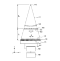
- FIG. 1 An example of the configuration of an X-ray imaging apparatus using Talbot interference is shown in FIG. A process until obtaining a phase image using an X-ray imaging apparatus will be specifically described.
- X-ray source X-rays 111 generated from the X-ray source 110 pass through the subject 120.
- X-ray 111 passes through the subject 120, a change in phase and absorption according to the composition, shape, and the like of the subject 120 occur.
- the X-ray either a continuous X-ray or a characteristic X-ray may be used.
- the wavelength is appropriately selected from about 0.1 to 5 mm.
- a wavelength selection filter or a grating for the radiation source may be provided as appropriate.
- phase grating When the X-ray 111 transmitted through the subject 120 passes through the phase grating 130, an interference intensity distribution 140 is formed by the Talbot effect.
- the phase grating 130 is arranged on the upstream side or the downstream side of the subject 120.
- the phase grating 130 includes a phase advance portion 131 and a phase delay portion 132 that are configured by periodically changing the thickness of the X-ray transmitting member.
- the phase progression unit 131 and the phase delay unit 132 may be formed so as to have a phase difference with respect to the transmitted X-ray.
- the configuration is such that the phase of the X-ray transmitted through the phase advancer 131 advances by ⁇ with respect to the phase of the X-ray transmitted through the phase delay unit 132.
- the amount of change in thickness is determined by the wavelength and member of the X-ray used.
- the phase grating 130 modulates the phase of the X-ray transmitted through the phase delay unit 132 by ⁇ or ⁇ / 2 with respect to the phase of the X-ray transmitted through the phase delay unit 132.
- the former may be referred to as a ⁇ phase grating and the latter as a ⁇ / 2 phase grating.
- the phase modulation amount may be periodic, and may be, for example, ⁇ / 3 modulated.
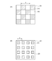
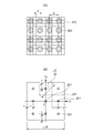
- the phase grating 130 may have a one-dimensional linear shape, or may be configured with a two-dimensional checkered pattern as shown in FIG. Moreover, you may be comprised by the screen door-like pattern as shown to FIG. 2 (B).
- d is a period
- 201 is a two-dimensional phase grating
- 210 is a phase progression unit
- 220 is a phase delay unit.
- phase advance part 210 or the phase delay part 220 is a square in FIG. 2 (A) and FIG. 2 (B)
- an outer edge may deform
- it can be used as a phase grating.
- phase grating 130 When the phase grating 130 has a one-dimensional period, only the phase gradient information of the subject 120 in the one-dimensional direction can be acquired. However, when the phase grating 130 has a two-dimensional period, it is advantageous in that phase gradient information in a two-dimensional direction can be acquired.
- the material constituting the phase grating 130 is preferably a substance that transmits X-rays.
- silicon or the like can be used.
- the interference intensity distribution formed after transmission through the phase grating 130 is the distance Z 0 between the X-ray source and the phase grating 130, the distance Z 1 from the absorption grating 150 satisfies the following formula (1). Appears most clearly.
- the “interference intensity distribution” is a periodic intensity distribution reflecting the grating period of the phase grating 130.
- ⁇ is the wavelength of the X-ray
- d is the grating period of the phase grating 130.
- N is a different value depending on the form of the phase grating, and is a real number that can be expressed as follows. Note that n is a natural number.
- One-dimensional array of ⁇ phase grating: N n / 4 ⁇ 1 / 8
- Two-dimensional checkered pattern ⁇ phase grating: N n / 4 ⁇ 1 / 8
- Two-dimensional checkered pattern ⁇ / 2 phase grating: N n / 2 ⁇ 1 / 4
- Absorption grid Since the period of the interference intensity distribution is generally smaller than the pixel size of the X-ray detector 170, the interference intensity distribution cannot be detected as it is. Therefore, by using the absorption grating 150, moire having a period larger than the pixel size of the X-ray detector 170 is generated, and the moire intensity distribution is detected by the X-ray detector 170.
- Absorption grating 150 is preferably provided apart from the phase grating 130 by the distance Z 1 position.
- the absorption grating 150 includes a transmission portion 151 and a light shielding portion 152 that are periodically arranged, and is arranged so as to shield a part of a bright portion of the interference intensity distribution 140 formed by the phase grating 130.
- the transmission part 151 should just be comprised so that a part of X-rays can permeate
- the material constituting the absorption grating 150 may be any material that absorbs X-rays well, and for example, gold can be used.
- the period of the absorption grating 150 is the same as or slightly different from the interference intensity distribution.
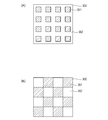
- the transmission portions 151 may be arranged one-dimensionally or two-dimensionally.
- the transmission part 351 and the light shielding part 352 are two-dimensionally arranged as shown in FIG.
- a screen door-shaped absorption grating 300 is used.
- the checkered ⁇ / 2 phase grating shown in FIG. 2A is used, a checkered pattern in which the transmission part 351 and the light shielding part 352 are two-dimensionally arranged as shown in FIG. 3B.
- the absorption grating 300 is used.
- phase grating and the absorption grating are possible.
- the X-ray detector 170 is an element that can detect information on the X-ray interference intensity distribution.
- an FPD Full Panel Detector
- FPD Full Panel Detector
- the arithmetic device 180 has, for example, a CPU (Central Processing Unit).
- the interference intensity distribution When the interference intensity distribution is formed, a large number of diffracted lights interfere and interfere with each other, and therefore include a fundamental frequency (hereinafter referred to as a carrier frequency) and a number of harmonic components thereof.
- a carrier frequency a fundamental frequency
- the moire since the moire has a shape in which the carrier frequency component of the interference intensity distribution is spatially enlarged, the moire can be expressed by equation (2) when a one-dimensional phase grating whose score line is orthogonal to the x axis is used. it can.
- Equation (2) indicates that moire is represented by the sum of the first term of the background and the second term having periodicity.
- a (x, y) represents the background
- b (x, y) represents the amplitude of the carrier frequency component.
- F 0 represents the carrier frequency of the interference fringes
- ⁇ (x, y) represents the phase of the carrier frequency component.
- the carrier frequency component is generated by the interference between the 0th-order diffracted light and the + 1st-order diffracted light, and the interference between the 0th-order diffracted light and the ⁇ 1st-order diffracted light. Further, when a checkered ⁇ phase grating is used as the phase grating 130, a carrier frequency component is generated due to interference between the + 1st order diffracted light and the ⁇ 1st order diffracted light.
- these interferences are shearing interference in which a shear amount s is Nd in the case of a ⁇ / 2 phase grating and a shear amount s is 2Nd in the case of a ⁇ phase grating.
- phase image of the subject 120 at the position of the phase grating 130 is W (x, y)
- the phase ⁇ (x, y) and the phase image W (x, y) have the following relationship.
- phase ⁇ (x, y) is information obtained by differentiating the phase image W (x, y) of the subject 120. Therefore, the phase image W (x, y) of the subject 120 can be obtained by integrating ⁇ (x, y).
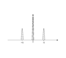
- FIG. 4 is a spectrum pattern of the interference intensity distribution when a one-dimensional grating is used. Usually, three peaks occur as shown in FIG. Central peak is the peak derived from predominantly A (f x, f y) to. On the other hand, the both sides of each peak C (f x, f y) and C * (f x, f y ) is the carrier frequency peak derived from, these peaks occur at the position of ⁇ f 0.
- the peaks derived from f y ) or C * (f x , f y ) are separated.
- phase ⁇ (x, y) that is, differential phase information is obtained from complex number information obtained by inverse Fourier transform.
- 5A shows a checkered ⁇ / 2 phase grating (FIG. 2A) and a screened absorption grating (FIG. 3A), or a checkered absorption grating (FIG. 3A).
- B)) is an example of the intensity distribution of moiré
- 510 is a bright portion of moiré
- 520 is a dark portion of moiré.
- a checkered ⁇ phase grating (FIG. 2A) and a checkered absorption grating (FIG. 3B) are used, a moire intensity distribution is generated in such an oblique direction.
- FIG. 5B shows the intensity distribution of moiré when a checkered ⁇ phase grating (FIG. 2A) and a screened absorption grating (FIG. 3A) are used.
- Moire light part 540 is a moire dark part. In this case, a moire intensity distribution is generated in the vertical and horizontal directions.
- moiré intensity distribution as described above can also be obtained using a screen door-shaped phase grating (FIG. 2B).
- FIGS. 5C and 5D are spatial frequencies obtained by performing FFT (Fast Fourier Transform) processing, which is a kind of Fourier transform, on the moire intensity distribution shown in FIGS. 5A and 5B, respectively. It is a spectrum.
- the maximum spatial frequency that can be calculated by FFT is 1 / (2P), where P is the pixel period of the X-ray detector 170.
- Each of the two peaks 570 and 571 and 580 and 581 at orthogonal positions is cut out in the same manner as in the above-described one-dimensional case, and moved to the origin to perform inverse Fourier transform.
- a broken line indicates a cutout region. Then, differential phase information in two orthogonal directions is obtained from the complex number information obtained by the inverse Fourier transform.
- the differential phase information is in the direction of ⁇ 45 degrees
- the differential phase information is in the X and Y directions.
- the differential phase information obtained in this way is often convoluted (wrapped) between 2 ⁇ regions. That is, if the true phase at any point on a screen is ⁇ (x, y) and the convolved phase is ⁇ wrap (x, y)
- n is an integer
- ⁇ wrap (x, y) is determined so as to be in a region having a width of 2 ⁇ , for example, between 0 to 2 ⁇ and ⁇ to + ⁇ .
- phase connection (unwrapping) of ⁇ (x, y) wrap is performed to restore the original ⁇ (x, y).
- phase image W (x, y) of the subject can be obtained by integrating ⁇ (x, y) restored by the equation (8).
- the integration direction can only be a direction orthogonal to the grid engraving direction. Therefore, in order to correctly measure the phase image W (x, y), the phase image is set so that one side parallel to the engraving direction of the X-ray detector 170 is irradiated with X-rays that do not pass through the subject 120. It is necessary to provide a portion where W (x, y) is known.
- phase image W (x, y) can be correctly measured even when the entire surface of the X-ray detector 170 is irradiated with X-rays passing through the subject 120.
- a peak separation step of cutting out a spectrum corresponding to the carrier frequency (a spectrum carrying the phase information) is performed (S631).
- a peak separation step of cutting out a spectrum corresponding to the carrier frequency (a spectrum carrying the phase information) is performed (S631).
- phase ⁇ (x, y) that is a differential phase image is obtained from the complex number information obtained in S632 (S633).
- S631, S632, and S633 may be referred to as a phase recovery step (S630).
- ⁇ (x, y) is wrapped, unwrap processing is performed to obtain true ⁇ (x, y) (S640). This is sometimes referred to as a phase connection process. If ⁇ (x, y) is not wrapped, this S640 can be omitted.
- ⁇ (x, y) is differential phase information (differential phase image).
- phase image W (x, y) is acquired by integrating ⁇ (x, y) (S650).
- an X-ray imaging apparatus and an X-ray imaging method capable of acquiring a phase image of a subject from at least one imaging. It is also possible to provide a program that causes a computer to execute the above steps.
- FIG. 7B shows the spatial frequency spectrum described in the present embodiment.
- the basic period of the two-dimensional moire generated in the interference intensity distribution and the absorption grating is set to the pixel period of the X-ray detector.
- the moiré direction is adjusted to be inclined 45 degrees with respect to the pixel array.
- FIG. 7A is a diagram showing the moire intensity distribution on the X-ray detector in such a state.
- 710 is a light receiving surface of the X-ray detector
- 720 is a bright portion of moire
- d is a moire cycle
- P is a pixel cycle of the X-ray detector.
- a checkered ⁇ / 2 phase grating (FIG. 2A) and a checkered absorption grating (FIG. 3B) are used.
- other phase gratings and absorption gratings may be used.
- FIG. 7B is a spatial frequency spectrum obtained by performing FFT processing on the moiré intensity distribution of FIG. 7A. If the number of pixel arrays is n both vertically and horizontally, the spectrum space obtained by FFT also becomes n ⁇ n discrete data. The maximum frequency that can be expressed is 1 / (2P) where P is the pixel period of the X-ray detector 170.
- a carrier peak 711 that is a peak corresponding to the carrier frequency of the moiré intensity distribution is generated at the position.
- the phase image of the subject can be restored.
- the spatial resolution can be increased by cutting out the spectral region as wide as possible.
- an unnecessary peak 721 that is the peak of the high frequency component and the DC component exists at the position of the sum or difference of the peak coordinates of the carrier frequency component.
- the cutout spectrum region is a cutout region 731 inside the intermediate line between the carrier frequency peak and the unnecessary peak 721.
- the spatial frequency of the phase image that can be restored in the present embodiment is 1 ⁇ 2 of the size of the cutout region 731. Therefore, as can be seen from FIG. 7B, the maximum frequency in the pixel array direction is 1 / (4P), and the maximum frequency in the 45 degree direction is
- the cutout region in FIG. 7B is wider than the cutout region in FIG. Therefore, according to the present embodiment, it is possible to improve the spatial resolution as compared with the above embodiment.
- FIG. 3 A third embodiment of the X-ray imaging apparatus according to the present invention will be described with reference to FIG. This embodiment is also devised to improve the spatial resolution compared to the spatial frequency spectrum of FIG. 5D described in the first embodiment.
- FIG. 8B shows the spatial frequency spectrum described in the present embodiment.
- the basic period of the two-dimensional moire generated in the interference intensity distribution and the absorption grating is set to three times the pixel period of the X-ray detector, and the direction of moire coincides with the pixel array.
- FIG. 8 (A) is a diagram showing the moire intensity distribution on the X-ray detector in such a state.
- 810 is a light receiving surface of the X-ray detector
- 820 is a bright portion of moire
- d is a moire cycle
- P is a pixel cycle of the X-ray detector.
- a checkered ⁇ phase grating (FIG. 2A) and a screen door absorption grating (FIG. 3A) are used.
- other phase gratings and absorption gratings may be used.
- FIG. 8A is a spatial frequency spectrum obtained by performing FFT processing on the moire intensity distribution shown in FIG. 8B.
- the absolute value of the carrier frequency is 1 / (3P). Therefore, in spectral space
- a carrier peak 811 that is a peak corresponding to the carrier frequency in the intensity distribution of the moire occurs.
- the process described in the first embodiment is performed. The phase image of the subject can be restored.
- the cutout spectral region is a cutout region 831 inside the intermediate line between the carrier frequency peak and the unnecessary peak 821.
- the spatial frequency of the phase image that can be restored in this embodiment is 1 ⁇ 2 of the size of the cutout region 831. Therefore, from FIG. 8B, the maximum frequency in the pixel array direction is 1 / (6P), and the maximum frequency in the 45 degree direction is
- the present embodiment is superior to the second embodiment in the spatial resolution in the direction of 45 degrees with respect to the pixel array.
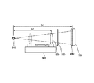
- the X-ray imaging apparatus according to the present embodiment is an X-ray imaging apparatus according to any one of Embodiments 1 to 3 equipped with an inspection object moving device 900.
- the subject moving device 900 can move the subject 920 in the X-ray optical axis direction.
- the imaging magnification of the subject 920 in the X-ray detector is L1 / L2 if the distance between the X-ray source 910 and the absorption grating 940 is L1, and the distance between the X-ray source 910 and the absorption grating 940 is L2.
- L2 becomes large, so that imaging can be performed at a low magnification.
- L2 becomes small, so that imaging can be performed at a high magnification.
Landscapes
- Physics & Mathematics (AREA)
- Engineering & Computer Science (AREA)
- Health & Medical Sciences (AREA)
- Life Sciences & Earth Sciences (AREA)
- General Physics & Mathematics (AREA)
- Chemical & Material Sciences (AREA)
- Spectroscopy & Molecular Physics (AREA)
- Pathology (AREA)
- General Health & Medical Sciences (AREA)
- Immunology (AREA)
- Analytical Chemistry (AREA)
- Biochemistry (AREA)
- High Energy & Nuclear Physics (AREA)
- Medical Informatics (AREA)
- Nuclear Medicine, Radiotherapy & Molecular Imaging (AREA)
- Radiology & Medical Imaging (AREA)
- General Engineering & Computer Science (AREA)
- Crystallography & Structural Chemistry (AREA)
- Theoretical Computer Science (AREA)
- Computer Vision & Pattern Recognition (AREA)
- Quality & Reliability (AREA)
- Molecular Biology (AREA)
- Heart & Thoracic Surgery (AREA)
- Surgery (AREA)
- Animal Behavior & Ethology (AREA)
- Public Health (AREA)
- Veterinary Medicine (AREA)
- Biomedical Technology (AREA)
- Optics & Photonics (AREA)
- Biophysics (AREA)
- Analysing Materials By The Use Of Radiation (AREA)
- Apparatus For Radiation Diagnosis (AREA)
- Measurement Of Radiation (AREA)
Priority Applications (9)
| Application Number | Priority Date | Filing Date | Title |
|---|---|---|---|
| EP09823593.0A EP2343537B1 (en) | 2008-10-29 | 2009-10-27 | X-ray imaging device and x-ray imaging method |
| JP2010535804A JP5174180B2 (ja) | 2008-10-29 | 2009-10-27 | X線撮像装置およびx線撮像方法 |
| DE112009002606.0T DE112009002606B4 (de) | 2008-10-29 | 2009-10-27 | Röntgenstrahlabbildungsgerät und Röntgenstrahlabbildungsverfahren |
| KR1020117011759A KR101258927B1 (ko) | 2008-10-29 | 2009-10-27 | X선 촬상장치 및 x선 촬상방법 |
| CN2009801428377A CN102197303A (zh) | 2008-10-29 | 2009-10-27 | X射线成像装置和x射线成像方法 |
| US12/842,937 US8009797B2 (en) | 2008-10-29 | 2010-07-23 | X-ray imaging apparatus, X-ray imaging method, and X-ray imaging program |
| US13/085,199 US8559594B2 (en) | 2008-10-29 | 2011-04-12 | Imaging apparatus and imaging method |
| US13/190,770 US8340243B2 (en) | 2008-10-29 | 2011-07-26 | X-ray imaging apparatus, X-ray imaging method, and X-ray imaging program |
| US13/682,445 US8537966B2 (en) | 2008-10-29 | 2012-11-20 | X-ray imaging apparatus, X-ray imaging method, and X-ray imaging program |
Applications Claiming Priority (2)
| Application Number | Priority Date | Filing Date | Title |
|---|---|---|---|
| JP2008-278425 | 2008-10-29 | ||
| JP2008278425 | 2008-10-29 |
Related Child Applications (1)
| Application Number | Title | Priority Date | Filing Date |
|---|---|---|---|
| US12/842,937 Continuation US8009797B2 (en) | 2008-10-29 | 2010-07-23 | X-ray imaging apparatus, X-ray imaging method, and X-ray imaging program |
Publications (1)
| Publication Number | Publication Date |
|---|---|
| WO2010050483A1 true WO2010050483A1 (ja) | 2010-05-06 |
Family
ID=41664696
Family Applications (2)
| Application Number | Title | Priority Date | Filing Date |
|---|---|---|---|
| PCT/JP2009/068434 WO2010050483A1 (ja) | 2008-10-29 | 2009-10-27 | X線撮像装置およびx線撮像方法 |
| PCT/JP2009/068863 WO2010050611A1 (en) | 2008-10-29 | 2009-10-28 | Analysis method, radiation imaging apparatus using analysis method, and analysis program for executing analysis method |
Family Applications After (1)
| Application Number | Title | Priority Date | Filing Date |
|---|---|---|---|
| PCT/JP2009/068863 WO2010050611A1 (en) | 2008-10-29 | 2009-10-28 | Analysis method, radiation imaging apparatus using analysis method, and analysis program for executing analysis method |
Country Status (8)
| Country | Link |
|---|---|
| US (5) | US8520799B2 (ko) |
| EP (2) | EP2343537B1 (ko) |
| JP (4) | JP5174180B2 (ko) |
| KR (1) | KR101258927B1 (ko) |
| CN (3) | CN102197303A (ko) |
| DE (1) | DE112009002606B4 (ko) |
| RU (1) | RU2519663C2 (ko) |
| WO (2) | WO2010050483A1 (ko) |
Cited By (34)
| Publication number | Priority date | Publication date | Assignee | Title |
|---|---|---|---|---|
| JP2012005820A (ja) * | 2010-05-27 | 2012-01-12 | Canon Inc | X線撮像装置 |
| WO2012023356A1 (ja) * | 2010-08-19 | 2012-02-23 | 富士フイルム株式会社 | 放射線撮影システム及びその画像処理方法 |
| WO2012038857A1 (en) * | 2010-09-20 | 2012-03-29 | Koninklijke Philips Electronics N.V. | Phase gradient unwrapping in differential phase contrast imaging |
| WO2012056724A1 (ja) * | 2010-10-29 | 2012-05-03 | 富士フイルム株式会社 | 放射線位相画像撮影装置 |
| JP2012103237A (ja) * | 2010-10-14 | 2012-05-31 | Canon Inc | 撮像装置 |
| JP2012108098A (ja) * | 2010-10-20 | 2012-06-07 | Canon Inc | トールボット干渉を用いた撮像装置および撮像装置の調整方法 |
| JP2012143553A (ja) * | 2010-12-24 | 2012-08-02 | Fujifilm Corp | 放射線画像撮影装置および放射線画像検出器 |
| WO2012128335A1 (ja) * | 2011-03-23 | 2012-09-27 | コニカミノルタエムジー株式会社 | 医用画像表示システム |
| JP2012187341A (ja) * | 2011-03-14 | 2012-10-04 | Canon Inc | X線撮像装置 |
| WO2012133553A1 (ja) * | 2011-03-29 | 2012-10-04 | 富士フイルム株式会社 | 放射線撮影システム及び放射線撮影方法 |
| WO2012147749A1 (ja) * | 2011-04-25 | 2012-11-01 | 富士フイルム株式会社 | 放射線撮影システム及び放射線撮影方法 |
| US20120275564A1 (en) * | 2011-04-26 | 2012-11-01 | Fujifilm Corporation | Radiation imaging apparatus |
| JP2012228371A (ja) * | 2011-04-26 | 2012-11-22 | Canon Inc | 撮像装置 |
| WO2012169427A1 (ja) * | 2011-06-10 | 2012-12-13 | 富士フイルム株式会社 | 放射線撮影システム |
| WO2012169426A1 (ja) * | 2011-06-08 | 2012-12-13 | 富士フイルム株式会社 | 放射線撮影システム |
| JP2013002845A (ja) * | 2011-06-13 | 2013-01-07 | Canon Inc | 撮像装置、干渉縞解析プログラム及び干渉縞解析方法 |
| WO2013027519A1 (ja) * | 2011-08-22 | 2013-02-28 | 富士フイルム株式会社 | 放射線撮影装置及びアンラップ処理方法 |
| JP2013050441A (ja) * | 2011-08-03 | 2013-03-14 | Canon Inc | 波面測定装置、波面測定方法、及びプログラム並びにx線撮像装置 |
| WO2013038881A1 (ja) * | 2011-09-12 | 2013-03-21 | 富士フイルム株式会社 | 放射線撮影装置及び画像処理方法 |
| WO2013047011A1 (ja) * | 2011-09-30 | 2013-04-04 | 富士フイルム株式会社 | 放射線画像検出器及びその製造方法、並びに放射線画像検出器を用いた放射線撮影システム |
| EP2578156A1 (en) | 2011-10-04 | 2013-04-10 | Fujifilm Corporation | Radiation imaging apparatus and image processing method |
| JP2013102951A (ja) * | 2011-11-14 | 2013-05-30 | Canon Inc | 撮像装置および画像処理方法 |
| JP2013536723A (ja) * | 2010-09-03 | 2013-09-26 | コーニンクレッカ フィリップス エヌ ヴェ | 微分位相差イメージングにおける正規化位相回復 |
| JP2013540031A (ja) * | 2010-10-19 | 2013-10-31 | コーニンクレッカ フィリップス エヌ ヴェ | 微分位相コントラスト画像形成 |
| JP2014108358A (ja) * | 2012-11-30 | 2014-06-12 | Canon Inc | 逆リース変換による差分画像の合成 |
| WO2014092206A1 (en) | 2012-12-13 | 2014-06-19 | Canon Kabushiki Kaisha | Object information obtaining apparatus, program, and imaging system |
| US8767916B2 (en) | 2011-04-20 | 2014-07-01 | Fujifilm Corporation | Radiation imaging apparatus and image processing method |
| JP2014121614A (ja) * | 2012-12-24 | 2014-07-03 | Canon Inc | 位相画像を再構成する方法、コンピュータ可読記憶媒体、及び装置 |
| EP2827339A1 (en) | 2013-07-16 | 2015-01-21 | Canon Kabushiki Kaisha | Source grating, interferometer, and object information acquisition system |
| EP2924972A1 (en) | 2014-03-27 | 2015-09-30 | Canon Kabushiki Kaisha | Image processing apparatus and imaging system |
| US9855018B2 (en) | 2013-04-08 | 2018-01-02 | Konica Minolta, Inc. | Diagnostic medical image system and method of introducing Talbot capturing device to diagnostic medical image system used for general capturing |
| EP3530189A1 (en) | 2018-02-23 | 2019-08-28 | Konica Minolta, Inc. | X-ray imaging system |
| WO2019240165A1 (ja) | 2018-06-12 | 2019-12-19 | 国立大学法人筑波大学 | 位相画像撮影方法とそれを利用した位相画像撮影装置 |
| US10725186B2 (en) | 2016-02-23 | 2020-07-28 | Canon Kabushiki Kaisha | Scintillator plate, radiation detector, and radiation measurement system |
Families Citing this family (65)
| Publication number | Priority date | Publication date | Assignee | Title |
|---|---|---|---|---|
| JP5339975B2 (ja) * | 2008-03-13 | 2013-11-13 | キヤノン株式会社 | X線位相イメージングに用いられる位相格子、該位相格子を用いたx線位相コントラスト像の撮像装置、x線コンピューター断層撮影システム |
| WO2010050483A1 (ja) * | 2008-10-29 | 2010-05-06 | キヤノン株式会社 | X線撮像装置およびx線撮像方法 |
| CN101943668B (zh) * | 2009-07-07 | 2013-03-27 | 清华大学 | X射线暗场成像系统和方法 |
| JP5586899B2 (ja) * | 2009-08-26 | 2014-09-10 | キヤノン株式会社 | X線用位相格子及びその製造方法 |
| US8532252B2 (en) * | 2010-01-27 | 2013-09-10 | Canon Kabushiki Kaisha | X-ray shield grating, manufacturing method therefor, and X-ray imaging apparatus |
| JP5631013B2 (ja) * | 2010-01-28 | 2014-11-26 | キヤノン株式会社 | X線撮像装置 |
| JP5725870B2 (ja) * | 2010-02-22 | 2015-05-27 | キヤノン株式会社 | X線撮像装置およびx線撮像方法 |
| US8995614B2 (en) * | 2010-09-29 | 2015-03-31 | Konica Minolta Medical & Graphic, Inc. | Method for displaying medical images and medical image display system |
| WO2012052881A1 (en) * | 2010-10-19 | 2012-04-26 | Koninklijke Philips Electronics N.V. | Differential phase-contrast imaging |
| JP2012095865A (ja) * | 2010-11-02 | 2012-05-24 | Fujifilm Corp | 放射線撮影装置、放射線撮影システム |
| JP2012200567A (ja) * | 2011-03-28 | 2012-10-22 | Fujifilm Corp | 放射線撮影システム及び放射線撮影方法 |
| JP2013024731A (ja) | 2011-07-21 | 2013-02-04 | Canon Inc | 放射線検出装置 |
| EP2586373B1 (en) * | 2011-10-28 | 2014-12-03 | CSEM Centre Suisse D'electronique Et De Microtechnique SA | X-ray interferometer |
| US20150117599A1 (en) | 2013-10-31 | 2015-04-30 | Sigray, Inc. | X-ray interferometric imaging system |
| US9597050B2 (en) * | 2012-01-24 | 2017-03-21 | Koninklijke Philips N.V. | Multi-directional phase contrast X-ray imaging |
| WO2013151342A1 (ko) * | 2012-04-05 | 2013-10-10 | 단국대학교 산학협력단 | 방사선 위상차 영상 장치 |
| JP2014006247A (ja) * | 2012-05-28 | 2014-01-16 | Canon Inc | 被検体情報取得装置、被検体情報取得方法及びプログラム |
| JP6079204B2 (ja) * | 2012-12-18 | 2017-02-15 | コニカミノルタ株式会社 | 医用画像システム |
| US10096098B2 (en) | 2013-12-30 | 2018-10-09 | Carestream Health, Inc. | Phase retrieval from differential phase contrast imaging |
| US10578563B2 (en) | 2012-12-21 | 2020-03-03 | Carestream Health, Inc. | Phase contrast imaging computed tomography scanner |
| US9357975B2 (en) | 2013-12-30 | 2016-06-07 | Carestream Health, Inc. | Large FOV phase contrast imaging based on detuned configuration including acquisition and reconstruction techniques |
| US9364191B2 (en) * | 2013-02-11 | 2016-06-14 | University Of Rochester | Method and apparatus of spectral differential phase-contrast cone-beam CT and hybrid cone-beam CT |
| KR20140111818A (ko) | 2013-03-12 | 2014-09-22 | 삼성전자주식회사 | 엑스선 영상 장치 및 그 제어 방법 |
| JP2014171799A (ja) * | 2013-03-12 | 2014-09-22 | Canon Inc | X線撮像装置及びx線撮像システム |
| JP2014178130A (ja) * | 2013-03-13 | 2014-09-25 | Canon Inc | X線撮像装置及びx線撮像システム |
| US10295485B2 (en) | 2013-12-05 | 2019-05-21 | Sigray, Inc. | X-ray transmission spectrometer system |
| US10416099B2 (en) | 2013-09-19 | 2019-09-17 | Sigray, Inc. | Method of performing X-ray spectroscopy and X-ray absorption spectrometer system |
| DE102013221818A1 (de) * | 2013-10-28 | 2015-04-30 | Siemens Aktiengesellschaft | Bildgebendes System und Verfahren zur Bildgebung |
| CN105637351B (zh) * | 2013-10-31 | 2018-11-13 | 国立大学法人东北大学 | 非破坏检查装置 |
| USRE48612E1 (en) | 2013-10-31 | 2021-06-29 | Sigray, Inc. | X-ray interferometric imaging system |
| JP6396472B2 (ja) | 2013-12-17 | 2018-09-26 | コーニンクレッカ フィリップス エヌ ヴェKoninklijke Philips N.V. | 走査微分位相コントラストシステムのための位相回復 |
| AU2013273822A1 (en) | 2013-12-23 | 2015-07-09 | Canon Kabushiki Kaisha | Modulation guided phase unwrapping |
| US10393681B2 (en) | 2014-02-14 | 2019-08-27 | Canon Kabushiki Kaisha | X-ray Talbot interferometer and X-ray Talbot interferometer system |
| JP2015166676A (ja) * | 2014-03-03 | 2015-09-24 | キヤノン株式会社 | X線撮像システム |
| JP6362914B2 (ja) * | 2014-04-30 | 2018-07-25 | キヤノンメディカルシステムズ株式会社 | X線診断装置及び画像処理装置 |
| US10401309B2 (en) | 2014-05-15 | 2019-09-03 | Sigray, Inc. | X-ray techniques using structured illumination |
| CN104111120B (zh) * | 2014-07-25 | 2017-05-31 | 中国科学院上海光学精密机械研究所 | 基于朗奇剪切干涉仪的相位提取方法 |
| JP2016032573A (ja) * | 2014-07-31 | 2016-03-10 | キヤノン株式会社 | トールボット干渉計、トールボット干渉システム、及び縞走査法 |
| MX2017006619A (es) * | 2014-11-24 | 2017-08-10 | Koninklijke Philips Nv | Sistema de formacion de imagenes y detector para la formacion de imagenes de tomosintesis de contraste de fase de rayos-x. |
| US10117629B2 (en) | 2014-12-03 | 2018-11-06 | Board Of Supervisors Of Louisiana State University And Agricultural And Mechanical College | High energy grating techniques |
| KR101636438B1 (ko) * | 2015-03-18 | 2016-07-05 | 제이피아이헬스케어 주식회사 | 단일 그리드를 이용한 pci 기반의 엑스선 영상 생성 방법 및 그 장치 |
| JP6604772B2 (ja) * | 2015-08-05 | 2019-11-13 | キヤノン株式会社 | X線トールボット干渉計 |
| JP6608246B2 (ja) * | 2015-10-30 | 2019-11-20 | キヤノン株式会社 | X線回折格子及びx線トールボット干渉計 |
| DE102015226571B4 (de) * | 2015-12-22 | 2019-10-24 | Carl Zeiss Smt Gmbh | Vorrichtung und Verfahren zur Wellenfrontanalyse |
| JP6613988B2 (ja) * | 2016-03-30 | 2019-12-04 | コニカミノルタ株式会社 | 放射線撮影システム |
| DE102016206559B3 (de) * | 2016-04-19 | 2017-06-08 | Siemens Healthcare Gmbh | Verfahren zur Korrektur eines Röntgenbilds auf Effekte eines Streustrahlenrasters, Röntgeneinrichtung, Computerprogramm und elektronisch lesbarer Datenträger |
| US10247683B2 (en) | 2016-12-03 | 2019-04-02 | Sigray, Inc. | Material measurement techniques using multiple X-ray micro-beams |
| CN109087348B (zh) * | 2017-06-14 | 2022-04-29 | 北京航空航天大学 | 一种基于自适应区域投射的单像素成像方法 |
| JP6838531B2 (ja) * | 2017-09-06 | 2021-03-03 | 株式会社島津製作所 | 放射線位相差撮影装置 |
| JP6835242B2 (ja) * | 2017-10-11 | 2021-02-24 | 株式会社島津製作所 | X線位相差撮影システムおよび位相コントラスト画像補正方法 |
| US10578566B2 (en) | 2018-04-03 | 2020-03-03 | Sigray, Inc. | X-ray emission spectrometer system |
| DE112019002822T5 (de) | 2018-06-04 | 2021-02-18 | Sigray, Inc. | Wellenlängendispersives röntgenspektrometer |
| JP7117452B2 (ja) | 2018-07-26 | 2022-08-12 | シグレイ、インコーポレイテッド | 高輝度反射型x線源 |
| US10656105B2 (en) | 2018-08-06 | 2020-05-19 | Sigray, Inc. | Talbot-lau x-ray source and interferometric system |
| DE112019004433T5 (de) | 2018-09-04 | 2021-05-20 | Sigray, Inc. | System und verfahren für röntgenstrahlfluoreszenz mit filterung |
| CN112823280A (zh) | 2018-09-07 | 2021-05-18 | 斯格瑞公司 | 用于深度可选x射线分析的系统和方法 |
| DE102019111463A1 (de) * | 2019-05-03 | 2020-11-05 | Wipotec Gmbh | Röntgenstrahlungsdetektorvorrichtung und Vorrichtung zur Röntgeninspektion von Produkten, insbesondere von Lebensmitteln |
| DE112020004169T5 (de) | 2019-09-03 | 2022-05-25 | Sigray, Inc. | System und verfahren zur computergestützten laminografieröntgenfluoreszenz-bildgebung |
| CN111089871B (zh) * | 2019-12-12 | 2022-12-09 | 中国科学院苏州生物医学工程技术研究所 | X射线光栅相衬图像的相位信息分离方法及系统、储存介质、设备 |
| US11175243B1 (en) | 2020-02-06 | 2021-11-16 | Sigray, Inc. | X-ray dark-field in-line inspection for semiconductor samples |
| CN115667896A (zh) | 2020-05-18 | 2023-01-31 | 斯格瑞公司 | 使用晶体分析器和多个检测器元件的x射线吸收光谱的系统和方法 |
| WO2022061347A1 (en) | 2020-09-17 | 2022-03-24 | Sigray, Inc. | System and method using x-rays for depth-resolving metrology and analysis |
| WO2022126071A1 (en) | 2020-12-07 | 2022-06-16 | Sigray, Inc. | High throughput 3d x-ray imaging system using a transmission x-ray source |
| WO2023215204A1 (en) | 2022-05-02 | 2023-11-09 | Sigray, Inc. | X-ray sequential array wavelength dispersive spectrometer |
| CN117475172B (zh) * | 2023-12-28 | 2024-03-26 | 湖北工业大学 | 一种基于深度学习的高噪声环境相位图解包裹方法和系统 |
Citations (8)
| Publication number | Priority date | Publication date | Assignee | Title |
|---|---|---|---|---|
| JP2003090807A (ja) * | 2001-09-19 | 2003-03-28 | Hitachi Ltd | X線撮像法 |
| WO2004058070A1 (ja) * | 2002-12-26 | 2004-07-15 | Atsushi Momose | X線撮像装置および撮像方法 |
| US20050117699A1 (en) | 2003-11-28 | 2005-06-02 | Akio Yoneyama | X-ray imaging apparatus and x-ray imaging method |
| DE102006037257A1 (de) | 2006-02-01 | 2007-08-02 | Siemens Ag | Verfahren und Messanordnung zur zerstörungsfreien Analyse eines Untersuchungsobjektes durch Röntgenstrahlung |
| JP2008026098A (ja) * | 2006-07-20 | 2008-02-07 | Hitachi Ltd | X線撮像装置及び撮像方法 |
| JP2008200359A (ja) * | 2007-02-21 | 2008-09-04 | Konica Minolta Medical & Graphic Inc | X線撮影システム |
| JP2008200360A (ja) * | 2007-02-21 | 2008-09-04 | Konica Minolta Medical & Graphic Inc | X線撮影システム |
| JP2009244260A (ja) * | 2008-03-13 | 2009-10-22 | Canon Inc | X線位相イメージングに用いられる位相格子、該位相格子を用いたx線位相コントラスト像の撮像装置、x線コンピューター断層撮影システム |
Family Cites Families (14)
| Publication number | Priority date | Publication date | Assignee | Title |
|---|---|---|---|---|
| SU1673933A1 (ru) * | 1988-12-28 | 1991-08-30 | Ереванский политехнический институт им.К.Маркса | Рентгеноинтерферометрический способ исследовани кристаллов |
| SU1748030A1 (ru) * | 1990-06-07 | 1992-07-15 | Ереванский политехнический институт им.К.Маркса | Способ получени рентгеновских проекционных топограмм |
| US5424743A (en) * | 1994-06-01 | 1995-06-13 | U.S. Department Of Energy | 2-D weighted least-squares phase unwrapping |
| US5812629A (en) | 1997-04-30 | 1998-09-22 | Clauser; John F. | Ultrahigh resolution interferometric x-ray imaging |
| JP2000088772A (ja) * | 1998-09-11 | 2000-03-31 | Hitachi Ltd | X線撮像装置 |
| US7268891B2 (en) * | 2003-01-15 | 2007-09-11 | Asml Holding N.V. | Transmission shear grating in checkerboard configuration for EUV wavefront sensor |
| JP2006263180A (ja) * | 2005-03-24 | 2006-10-05 | Fuji Photo Film Co Ltd | 画像処理装置およびこれを用いた放射線撮影システム |
| EP1731099A1 (en) * | 2005-06-06 | 2006-12-13 | Paul Scherrer Institut | Interferometer for quantitative phase contrast imaging and tomography with an incoherent polychromatic x-ray source |
| CN101011257B (zh) * | 2006-02-01 | 2011-07-06 | 西门子公司 | 产生投影或断层造影相位对比图像的焦点-检测器装置 |
| DE102006063048B3 (de) * | 2006-02-01 | 2018-03-29 | Siemens Healthcare Gmbh | Fokus/Detektor-System einer Röntgenapparatur zur Erzeugung von Phasenkontrastaufnahmen |
| JP2008197593A (ja) * | 2007-02-16 | 2008-08-28 | Konica Minolta Medical & Graphic Inc | X線用透過型回折格子、x線タルボ干渉計およびx線撮像装置 |
| WO2008102598A1 (ja) * | 2007-02-21 | 2008-08-28 | Konica Minolta Medical & Graphic, Inc. | 放射線画像撮影装置及び放射線画像撮影システム |
| WO2010050483A1 (ja) * | 2008-10-29 | 2010-05-06 | キヤノン株式会社 | X線撮像装置およびx線撮像方法 |
| JP2010253157A (ja) * | 2009-04-28 | 2010-11-11 | Konica Minolta Medical & Graphic Inc | X線干渉計撮影装置及びx線干渉計撮影方法 |
-
2009
- 2009-10-27 WO PCT/JP2009/068434 patent/WO2010050483A1/ja active Application Filing
- 2009-10-27 CN CN2009801428377A patent/CN102197303A/zh active Pending
- 2009-10-27 KR KR1020117011759A patent/KR101258927B1/ko not_active IP Right Cessation
- 2009-10-27 EP EP09823593.0A patent/EP2343537B1/en active Active
- 2009-10-27 CN CN201410089754.9A patent/CN103876761B/zh active Active
- 2009-10-27 DE DE112009002606.0T patent/DE112009002606B4/de active Active
- 2009-10-27 JP JP2010535804A patent/JP5174180B2/ja active Active
- 2009-10-28 WO PCT/JP2009/068863 patent/WO2010050611A1/en active Application Filing
- 2009-10-28 JP JP2011514216A patent/JP5456032B2/ja not_active Expired - Fee Related
- 2009-10-28 EP EP09788095A patent/EP2342551A1/en not_active Withdrawn
- 2009-10-28 CN CN2009801423636A patent/CN102197302B/zh not_active Expired - Fee Related
- 2009-10-28 US US13/060,112 patent/US8520799B2/en not_active Expired - Fee Related
-
2010
- 2010-07-23 US US12/842,937 patent/US8009797B2/en active Active
-
2011
- 2011-07-26 US US13/190,770 patent/US8340243B2/en not_active Expired - Fee Related
-
2012
- 2012-09-05 RU RU2012137875/28A patent/RU2519663C2/ru not_active IP Right Cessation
- 2012-11-20 US US13/682,445 patent/US8537966B2/en active Active
- 2012-12-27 JP JP2012284424A patent/JP5595473B2/ja active Active
-
2013
- 2013-07-17 US US13/943,932 patent/US8681934B2/en not_active Expired - Fee Related
-
2014
- 2014-08-07 JP JP2014161638A patent/JP2014205079A/ja active Pending
Patent Citations (10)
| Publication number | Priority date | Publication date | Assignee | Title |
|---|---|---|---|---|
| JP2003090807A (ja) * | 2001-09-19 | 2003-03-28 | Hitachi Ltd | X線撮像法 |
| WO2004058070A1 (ja) * | 2002-12-26 | 2004-07-15 | Atsushi Momose | X線撮像装置および撮像方法 |
| US20050286680A1 (en) | 2002-12-26 | 2005-12-29 | Atsushi Momose | X-ray imaging system and imaging method |
| US20050117699A1 (en) | 2003-11-28 | 2005-06-02 | Akio Yoneyama | X-ray imaging apparatus and x-ray imaging method |
| JP2005152500A (ja) * | 2003-11-28 | 2005-06-16 | Hitachi Ltd | X線撮像装置及び撮像方法 |
| DE102006037257A1 (de) | 2006-02-01 | 2007-08-02 | Siemens Ag | Verfahren und Messanordnung zur zerstörungsfreien Analyse eines Untersuchungsobjektes durch Röntgenstrahlung |
| JP2008026098A (ja) * | 2006-07-20 | 2008-02-07 | Hitachi Ltd | X線撮像装置及び撮像方法 |
| JP2008200359A (ja) * | 2007-02-21 | 2008-09-04 | Konica Minolta Medical & Graphic Inc | X線撮影システム |
| JP2008200360A (ja) * | 2007-02-21 | 2008-09-04 | Konica Minolta Medical & Graphic Inc | X線撮影システム |
| JP2009244260A (ja) * | 2008-03-13 | 2009-10-22 | Canon Inc | X線位相イメージングに用いられる位相格子、該位相格子を用いたx線位相コントラスト像の撮像装置、x線コンピューター断層撮影システム |
Non-Patent Citations (2)
| Title |
|---|
| M. JIANG ET AL.: "X-Ray Phase-Contrast Imaging with Three 2D Gratings", INTERNATIONAL JOURNAL OF BIOMEDICAL IMAGING, vol. 2008, 24 March 2008 (2008-03-24), pages 1 - 8, XP002671455, DOI: doi:10.1155/2008/827152 |
| See also references of EP2343537A4 |
Cited By (46)
| Publication number | Priority date | Publication date | Assignee | Title |
|---|---|---|---|---|
| JP2012005820A (ja) * | 2010-05-27 | 2012-01-12 | Canon Inc | X線撮像装置 |
| US8824629B2 (en) | 2010-08-19 | 2014-09-02 | Fujifilm Corporation | Radiation imaging system and image processing method |
| WO2012023356A1 (ja) * | 2010-08-19 | 2012-02-23 | 富士フイルム株式会社 | 放射線撮影システム及びその画像処理方法 |
| CN103068311A (zh) * | 2010-08-19 | 2013-04-24 | 富士胶片株式会社 | 放射线摄影系统及其图像处理方法 |
| JP2012061300A (ja) * | 2010-08-19 | 2012-03-29 | Fujifilm Corp | 放射線撮影システム及びその画像処理方法 |
| JP2013536723A (ja) * | 2010-09-03 | 2013-09-26 | コーニンクレッカ フィリップス エヌ ヴェ | 微分位相差イメージングにおける正規化位相回復 |
| WO2012038857A1 (en) * | 2010-09-20 | 2012-03-29 | Koninklijke Philips Electronics N.V. | Phase gradient unwrapping in differential phase contrast imaging |
| JP2012103237A (ja) * | 2010-10-14 | 2012-05-31 | Canon Inc | 撮像装置 |
| JP2013540031A (ja) * | 2010-10-19 | 2013-10-31 | コーニンクレッカ フィリップス エヌ ヴェ | 微分位相コントラスト画像形成 |
| JP2012108098A (ja) * | 2010-10-20 | 2012-06-07 | Canon Inc | トールボット干渉を用いた撮像装置および撮像装置の調整方法 |
| US9194825B2 (en) | 2010-10-20 | 2015-11-24 | Canon Kabushiki Kaisha | Imaging apparatus using talbot interference and adjusting method for imaging apparatus |
| CN103188996A (zh) * | 2010-10-29 | 2013-07-03 | 富士胶片株式会社 | 放射线照相相衬成像设备 |
| WO2012056724A1 (ja) * | 2010-10-29 | 2012-05-03 | 富士フイルム株式会社 | 放射線位相画像撮影装置 |
| US8781069B2 (en) | 2010-10-29 | 2014-07-15 | Fujifilm Corporation | Radiographic phase-contrast imaging apparatus |
| JP5796908B2 (ja) * | 2010-10-29 | 2015-10-21 | 富士フイルム株式会社 | 放射線位相画像撮影装置 |
| JP2012143553A (ja) * | 2010-12-24 | 2012-08-02 | Fujifilm Corp | 放射線画像撮影装置および放射線画像検出器 |
| JP2012187341A (ja) * | 2011-03-14 | 2012-10-04 | Canon Inc | X線撮像装置 |
| JP5915645B2 (ja) * | 2011-03-23 | 2016-05-11 | コニカミノルタ株式会社 | 医用画像表示システム |
| WO2012128335A1 (ja) * | 2011-03-23 | 2012-09-27 | コニカミノルタエムジー株式会社 | 医用画像表示システム |
| WO2012133553A1 (ja) * | 2011-03-29 | 2012-10-04 | 富士フイルム株式会社 | 放射線撮影システム及び放射線撮影方法 |
| US8767916B2 (en) | 2011-04-20 | 2014-07-01 | Fujifilm Corporation | Radiation imaging apparatus and image processing method |
| WO2012147749A1 (ja) * | 2011-04-25 | 2012-11-01 | 富士フイルム株式会社 | 放射線撮影システム及び放射線撮影方法 |
| US20120275564A1 (en) * | 2011-04-26 | 2012-11-01 | Fujifilm Corporation | Radiation imaging apparatus |
| JP2012228371A (ja) * | 2011-04-26 | 2012-11-22 | Canon Inc | 撮像装置 |
| WO2012169426A1 (ja) * | 2011-06-08 | 2012-12-13 | 富士フイルム株式会社 | 放射線撮影システム |
| WO2012169427A1 (ja) * | 2011-06-10 | 2012-12-13 | 富士フイルム株式会社 | 放射線撮影システム |
| JP2013002845A (ja) * | 2011-06-13 | 2013-01-07 | Canon Inc | 撮像装置、干渉縞解析プログラム及び干渉縞解析方法 |
| JP2013050441A (ja) * | 2011-08-03 | 2013-03-14 | Canon Inc | 波面測定装置、波面測定方法、及びプログラム並びにx線撮像装置 |
| WO2013027519A1 (ja) * | 2011-08-22 | 2013-02-28 | 富士フイルム株式会社 | 放射線撮影装置及びアンラップ処理方法 |
| WO2013038881A1 (ja) * | 2011-09-12 | 2013-03-21 | 富士フイルム株式会社 | 放射線撮影装置及び画像処理方法 |
| WO2013047011A1 (ja) * | 2011-09-30 | 2013-04-04 | 富士フイルム株式会社 | 放射線画像検出器及びその製造方法、並びに放射線画像検出器を用いた放射線撮影システム |
| EP2578156A1 (en) | 2011-10-04 | 2013-04-10 | Fujifilm Corporation | Radiation imaging apparatus and image processing method |
| JP2013102951A (ja) * | 2011-11-14 | 2013-05-30 | Canon Inc | 撮像装置および画像処理方法 |
| JP2014108358A (ja) * | 2012-11-30 | 2014-06-12 | Canon Inc | 逆リース変換による差分画像の合成 |
| JP2014117336A (ja) * | 2012-12-13 | 2014-06-30 | Canon Inc | 演算装置、プログラム及び撮像システム |
| WO2014092206A1 (en) | 2012-12-13 | 2014-06-19 | Canon Kabushiki Kaisha | Object information obtaining apparatus, program, and imaging system |
| US20150308967A1 (en) * | 2012-12-13 | 2015-10-29 | Canon Kabushiki Kaisha | Object information obtaining apparatus, program, and imaging system |
| US9702831B2 (en) | 2012-12-13 | 2017-07-11 | Canon Kabushiki Kaisha | Object information obtaining apparatus, program, and imaging system |
| JP2014121614A (ja) * | 2012-12-24 | 2014-07-03 | Canon Inc | 位相画像を再構成する方法、コンピュータ可読記憶媒体、及び装置 |
| US9855018B2 (en) | 2013-04-08 | 2018-01-02 | Konica Minolta, Inc. | Diagnostic medical image system and method of introducing Talbot capturing device to diagnostic medical image system used for general capturing |
| EP2827339A1 (en) | 2013-07-16 | 2015-01-21 | Canon Kabushiki Kaisha | Source grating, interferometer, and object information acquisition system |
| EP2924972A1 (en) | 2014-03-27 | 2015-09-30 | Canon Kabushiki Kaisha | Image processing apparatus and imaging system |
| US10725186B2 (en) | 2016-02-23 | 2020-07-28 | Canon Kabushiki Kaisha | Scintillator plate, radiation detector, and radiation measurement system |
| EP3530189A1 (en) | 2018-02-23 | 2019-08-28 | Konica Minolta, Inc. | X-ray imaging system |
| WO2019240165A1 (ja) | 2018-06-12 | 2019-12-19 | 国立大学法人筑波大学 | 位相画像撮影方法とそれを利用した位相画像撮影装置 |
| US11181487B2 (en) | 2018-06-12 | 2021-11-23 | University Of Tsukuba | Phase imaging method and phase imaging apparatus using phase imaging method |
Also Published As
Similar Documents
| Publication | Publication Date | Title |
|---|---|---|
| JP5595473B2 (ja) | 被検体情報取得装置、x線撮像装置、被検体情報取得方法及びプログラム | |
| JP6422123B2 (ja) | 放射線画像生成装置 | |
| JP5777360B2 (ja) | X線撮像装置 | |
| JP5538936B2 (ja) | 解析方法、プログラム、記憶媒体、x線位相イメージング装置 | |
| JP4445397B2 (ja) | X線撮像装置および撮像方法 | |
| JP2013063099A (ja) | X線撮像装置 | |
| JP2011153969A (ja) | X線撮像装置、波面計測装置 | |
| JP2011174715A (ja) | X線撮像装置 | |
| JP2012005820A (ja) | X線撮像装置 | |
| CN105992557B (zh) | X射线Talbot干涉仪和X射线Talbot干涉仪系统 | |
| JP2018102558A (ja) | X線位相撮影装置 | |
| JP2013164339A (ja) | X線撮像装置 | |
| WO2015156379A1 (en) | Image processing unit and control method for image processing unit | |
| JP7180566B2 (ja) | X線イメージング装置およびx線イメージング方法 | |
| JP2017090414A (ja) | 二次元干渉パターン撮像装置 | |
| RU2472137C1 (ru) | Устройство формирования рентгеновских изображений и способ формирования рентгеновских изображений | |
| WO2018168621A1 (ja) | 放射線画像生成装置 | |
| JP2013042983A (ja) | トモシンセシス撮像装置及びトモシンセシス画像の撮像方法 | |
| WO2013051647A1 (ja) | 放射線撮影装置及び画像処理方法 | |
| JP2011237773A (ja) | 撮像装置及び撮像方法 | |
| JP2020038153A (ja) | 放射線画像生成装置 |
Legal Events
| Date | Code | Title | Description |
|---|---|---|---|
| WWE | Wipo information: entry into national phase |
Ref document number: 200980142837.7 Country of ref document: CN |
|
| 121 | Ep: the epo has been informed by wipo that ep was designated in this application |
Ref document number: 09823593 Country of ref document: EP Kind code of ref document: A1 |
|
| ENP | Entry into the national phase |
Ref document number: 2010535804 Country of ref document: JP Kind code of ref document: A |
|
| WWE | Wipo information: entry into national phase |
Ref document number: 2009823593 Country of ref document: EP |
|
| WWE | Wipo information: entry into national phase |
Ref document number: 1120090026060 Country of ref document: DE |
|
| ENP | Entry into the national phase |
Ref document number: 20117011759 Country of ref document: KR Kind code of ref document: A |
|
| WWE | Wipo information: entry into national phase |
Ref document number: 3616/CHENP/2011 Country of ref document: IN |
|
| WWE | Wipo information: entry into national phase |
Ref document number: 2011121670 Country of ref document: RU |