US9511555B2 - Tire vulcanizer-unloading device and tire vulcanizer - Google Patents
Tire vulcanizer-unloading device and tire vulcanizer Download PDFInfo
- Publication number
- US9511555B2 US9511555B2 US14/760,920 US201314760920A US9511555B2 US 9511555 B2 US9511555 B2 US 9511555B2 US 201314760920 A US201314760920 A US 201314760920A US 9511555 B2 US9511555 B2 US 9511555B2
- Authority
- US
- United States
- Prior art keywords
- tire
- section
- vulcanizer
- vulcanized
- vulcanized tire
- Prior art date
- Legal status (The legal status is an assumption and is not a legal conclusion. Google has not performed a legal analysis and makes no representation as to the accuracy of the status listed.)
- Active
Links
Images


Classifications
-
- B—PERFORMING OPERATIONS; TRANSPORTING
- B29—WORKING OF PLASTICS; WORKING OF SUBSTANCES IN A PLASTIC STATE IN GENERAL
- B29D—PRODUCING PARTICULAR ARTICLES FROM PLASTICS OR FROM SUBSTANCES IN A PLASTIC STATE
- B29D30/00—Producing pneumatic or solid tyres or parts thereof
- B29D30/06—Pneumatic tyres or parts thereof (e.g. produced by casting, moulding, compression moulding, injection moulding, centrifugal casting)
- B29D30/0601—Vulcanising tyres; Vulcanising presses for tyres
- B29D30/0603—Loading or unloading the presses
-
- B—PERFORMING OPERATIONS; TRANSPORTING
- B29—WORKING OF PLASTICS; WORKING OF SUBSTANCES IN A PLASTIC STATE IN GENERAL
- B29D—PRODUCING PARTICULAR ARTICLES FROM PLASTICS OR FROM SUBSTANCES IN A PLASTIC STATE
- B29D30/00—Producing pneumatic or solid tyres or parts thereof
- B29D30/0016—Handling tyres or parts thereof, e.g. supplying, storing, conveying
-
- B—PERFORMING OPERATIONS; TRANSPORTING
- B29—WORKING OF PLASTICS; WORKING OF SUBSTANCES IN A PLASTIC STATE IN GENERAL
- B29D—PRODUCING PARTICULAR ARTICLES FROM PLASTICS OR FROM SUBSTANCES IN A PLASTIC STATE
- B29D30/00—Producing pneumatic or solid tyres or parts thereof
- B29D30/06—Pneumatic tyres or parts thereof (e.g. produced by casting, moulding, compression moulding, injection moulding, centrifugal casting)
- B29D30/0601—Vulcanising tyres; Vulcanising presses for tyres
- B29D30/0633—After-treatment specially adapted for vulcanising tyres
- B29D30/0643—Cooling during post cure inflation; Post cure inflators used therefor
-
- B—PERFORMING OPERATIONS; TRANSPORTING
- B65—CONVEYING; PACKING; STORING; HANDLING THIN OR FILAMENTARY MATERIAL
- B65G—TRANSPORT OR STORAGE DEVICES, e.g. CONVEYORS FOR LOADING OR TIPPING, SHOP CONVEYOR SYSTEMS OR PNEUMATIC TUBE CONVEYORS
- B65G47/00—Article or material-handling devices associated with conveyors; Methods employing such devices
- B65G47/74—Feeding, transfer, or discharging devices of particular kinds or types
- B65G47/90—Devices for picking-up and depositing articles or materials
- B65G47/904—Devices for picking-up and depositing articles or materials provided with rotary movements only
-
- B—PERFORMING OPERATIONS; TRANSPORTING
- B65—CONVEYING; PACKING; STORING; HANDLING THIN OR FILAMENTARY MATERIAL
- B65G—TRANSPORT OR STORAGE DEVICES, e.g. CONVEYORS FOR LOADING OR TIPPING, SHOP CONVEYOR SYSTEMS OR PNEUMATIC TUBE CONVEYORS
- B65G65/00—Loading or unloading
-
- B—PERFORMING OPERATIONS; TRANSPORTING
- B29—WORKING OF PLASTICS; WORKING OF SUBSTANCES IN A PLASTIC STATE IN GENERAL
- B29D—PRODUCING PARTICULAR ARTICLES FROM PLASTICS OR FROM SUBSTANCES IN A PLASTIC STATE
- B29D30/00—Producing pneumatic or solid tyres or parts thereof
- B29D30/0016—Handling tyres or parts thereof, e.g. supplying, storing, conveying
- B29D2030/0027—Handling cured tyres, e.g. transferring or storing after vulcanizing
-
- B—PERFORMING OPERATIONS; TRANSPORTING
- B29—WORKING OF PLASTICS; WORKING OF SUBSTANCES IN A PLASTIC STATE IN GENERAL
- B29K—INDEXING SCHEME ASSOCIATED WITH SUBCLASSES B29B, B29C OR B29D, RELATING TO MOULDING MATERIALS OR TO MATERIALS FOR MOULDS, REINFORCEMENTS, FILLERS OR PREFORMED PARTS, e.g. INSERTS
- B29K2105/00—Condition, form or state of moulded material or of the material to be shaped
- B29K2105/24—Condition, form or state of moulded material or of the material to be shaped crosslinked or vulcanised
-
- B—PERFORMING OPERATIONS; TRANSPORTING
- B65—CONVEYING; PACKING; STORING; HANDLING THIN OR FILAMENTARY MATERIAL
- B65G—TRANSPORT OR STORAGE DEVICES, e.g. CONVEYORS FOR LOADING OR TIPPING, SHOP CONVEYOR SYSTEMS OR PNEUMATIC TUBE CONVEYORS
- B65G2201/00—Indexing codes relating to handling devices, e.g. conveyors, characterised by the type of product or load being conveyed or handled
- B65G2201/02—Articles
- B65G2201/0273—Tires
Definitions
- the present invention relates to an unloading device which transports a vulcanized tire in a tire vulcanizer, and a tire vulcanizer including the same.
- a tire vulcanizer in which a tire made of raw rubber formed in advance into a shape close to a finished product is put into a mold, and the tire is subjected to a vulcanization process by applying heat and pressure to the tire so as to be finished into a shape of a finished tire is known.
- a cooling device which receives the vulcanized tire from the mold and cools the vulcanized tire, and an unloading device which transfers the vulcanized tire to a discharge conveyor are provided.
- the unloading device for example, there is a device described in PTL 1. This device transports the tire between the position of the mold, the position of a post-cure inflator (cooling device), and the position of the discharge conveyor by rotating a turning arm while gripping the vulcanized tire.
- the mold, the post-cure inflator (cooling device), and the discharge conveyor need to be arranged so that the positions thereof where the tire is received and transferred are on the same rotational path of the turning arm of the unloading device.
- the mold, the post-cure inflator (cooling device), and the discharge conveyor need to be arranged at positions where they do not interfere with each other during the processing of the tire. Therefore, due to the two limitations regarding the arrangement, the length dimension of the turning arm is determined. Accordingly, further reduction in the length dimension of the turning arm is difficult, and it is difficult to achieve a further compact size of the tire vulcanizer using the same structure.
- the present invention has been made taking foregoing problems into consideration, and an object thereof is to provide an unloading device of a tire vulcanizer capable of achieving a compact size and space saving, and a tire vulcanizer.
- an unloading device of a tire vulcanizer in which a vulcanized tire vulcanized by a vulcanizer main body is taken out of a mold installed in the vulcanizer main body and is transported to a cooling position at which the vulcanized tire is cooled, and the vulcanized tire cooled at the cooling position is transported to a discharge position for transfer to an exporting device for discharging the vulcanized tire, includes: a support section which is able to support the vulcanized tire; a rotational movement section which rotates the support section in a plan view; and a linear movement section which linearly moves the support section.
- the rotational center of the support section may be positioned outside the support section.
- the rotational movement of the support section and the linear movement of the support section may be performed on the same virtual plane or on virtual planes parallel to each other.
- the unloading device when the vulcanized tire is supported and transported by the support section, transportation as a combination of rotational movement and linear movement can be achieved by the rotational movement section and the linear movement section. Therefore, unlike in a case where the vulcanized tire is transported only by rotational movement, there is no need to arrange the position of the mold installed in the vulcanizer main body, the cooling position, and the discharge position on the same rotational path, and this positional arrangement increases the degree of freedom.
- the device components at each of the position of the mold installed in the vulcanizer main body, the cooling position, and the discharge position and the vulcanized tire at each of the positions do not interfere with each other, and the vulcanized tire can be transported to the positions. Therefore, the rotational radius of the support section is suppressed, and thus the width dimension of the tire vulcanizer can be reduced.
- the installation pitch therebetween can be reduced, and the tires output can be increased within the same spatial area.
- a length dimension to the rotational center of the support section can be reduced, and thus a reduction in the cost of materials for the support section is possible.
- the length dimension of the support section can be reduced as described above, a reduction in the bending moment is possible, and thus strength required of the peripheral members that support the rotational center of the support section in the rotational movement section can be suppressed, resulting in a reduction in the weight and the cost of materials for the tire vulcanizer.
- the rotational radius of the support section is suppressed to be small, time needed for the transportation of the vulcanized tire can be reduced, and thus the cycle time during tire production can be reduced, resulting in an increase in the tires output.
- the linear movement section may be able to move along a direction toward the discharge position from the vulcanizer main body, and the rotational movement section may be rotatably supported by the linear movement section.
- rotational movement section is supported by the linear movement section as described above, movement as a combination of rotational movement and linear movement can be realized with a simple structure. Therefore, while suppressing the rotational radius of the support section to be small, the transportation of the vulcanized tire from the mold of the vulcanizer main body to the discharge position is possible.
- the rotational movement section may rotate the vulcanized tire from a position where the vulcanized tire is taken out of the mold, to the cooling position, and the linear movement section linearly may move the vulcanized tire from the cooling position to the discharge position.
- the stroke of the cylinder can be reduced. That is, if the movement from the position of the mold to the cooling position is linear movement, the vulcanized tire needs to be linearly moved to a position where the external shape of the mold does not interfere with the vulcanized tire, and thus in a case where a slide cylinder is used in the linear movement section, the stroke of the cylinder is increased. Therefore, by setting the movement from the position of the mold to the cooling position to rotational movement, there are advantages in terms of space saving and cost.
- An elevating section which vertically elevates the linear movement section may also be included.
- the elevating section is provided as described above, the degree of freedom in the movement paths of the support section, the rotational movement section, and the linear movement section is increased.
- a detection unit which detects a height position of the linear movement section; and a controller which controls the elevating section on the basis of the height position detected by the detection unit may also be included.
- the elevating section is controlled by detecting the height position at the detection unit, the support section, the rotational movement section, and the linear movement section can be positioned at appropriate positions in the height direction.
- an unloading device of a tire vulcanizer in which a vulcanized tire vulcanized by a vulcanizer main body is taken out of a mold installed in the vulcanizer main body and is transported to a cooling position at which the vulcanized tire is cooled, and the vulcanized tire cooled at the cooling position is transported to a discharge position for transfer to an exporting device for discharging the vulcanized tire, includes: a support section which is able to support the vulcanized tire; and a linear movement section which linearly moves the support section.
- the vulcanized tire can be transported without rotating the support section, and thus the width dimension of the tire vulcanizer can be reduced, resulting in a compact size.
- the installation pitch therebetween in the width direction can be reduced, and thus space saving in the width direction can be achieved.
- a tire vulcanizer of the present invention includes: any one of the above-described unloading device; a vulcanizer main body which performs vulcanization on a green tire which is not vulcanized; a post-cure inflator which cools the vulcanized tire vulcanized by the vulcanizer main body, at the cooling position; and an exporting device for discharging the vulcanized tire cooled at the cooling position.
- the width dimension of the tire vulcanizer can be reduced compared to a case where the transportation to the cooling position or the discharge position is performed only by rotational movement.
- the installation pitch between the tire vulcanizers can be reduced, and the tires output can be increased within the same spatial area.
- the post-cure inflator may be fixed to the vulcanizer main body.
- the vulcanizer main body and the post-cure inflator can be installed to be close to each other, and thus further reduction in the installation space is possible.
- the support section is moved by a combination of the rotational movement section and the linear movement section or by the linear movement section, a compact size of the devices and space saving can be achieved.
- FIG. 1 is a side view of a tire vulcanizer according to an embodiment of the present invention and illustrates a state at the end of a vulcanization process at a vulcanization position.
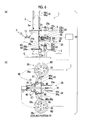
- FIG. 2 is a partial cutaway plan view illustrating the tire vulcanizer according to the embodiment of the present invention and illustrates the relationship between the arrangement positions of a green tire and a vulcanized tire in the tire vulcanizer.
- FIG. 3 is a side view of the tire vulcanizer according to the embodiment of the present invention and illustrates main parts of FIG. 1 .
- FIG. 4 relates to the tire vulcanizer according to the embodiment of the present invention and illustrates a state where the vulcanized tire is supported by a support section after the end of vulcanization in a vulcanizer main body, in which FIG. 4( a ) is a side view and FIG. 4( b ) is a partial plan view.
- FIG. 5 is a side view of the tire vulcanizer according to the embodiment of the present invention and illustrates a state where the vulcanized tire is transported after the end of the vulcanization process in the vulcanizer main body.
- FIG. 6 relates to the tire vulcanizer according to the embodiment of the present invention and illustrates a state after the vulcanized tire is transported to a cooling position, in which FIG. 6( a ) is a side view and FIG. 6( b ) is a partial plan view.
- FIG. 7 is a side view of the tire vulcanizer according to the embodiment of the present invention and illustrates a state where the vulcanized tire is set in a post-cure inflator at the cooling position.
- FIG. 8 relates to the tire vulcanizer according to the embodiment of the present invention and illustrates a state where the support section is evacuated after the vulcanized tire is set in a lower rim elevating device of the post-cure inflator, in which FIG. 8( a ) is a side view and FIG. 8( b ) is a partial plan view.
- FIG. 9 is a side view of the tire vulcanizer according to the embodiment of the present invention and illustrates a state where the vulcanized tire is set in the post-cure inflator.
- FIG. 10 is a side view of the tire vulcanizer according to the embodiment of the present invention and illustrates a state where a cooling process of the vulcanized tire is performed in the post-cure inflator.
- FIG. 11 is a side view of the tire vulcanizer according to the embodiment of the present invention and illustrates a state after the completion of the cooling process of the vulcanized tire in the post-cure inflator.
- FIG. 12 is a side view of the tire vulcanizer according to the embodiment of the present invention and illustrates a state after the completion of the cooling process and before the start of the transportation of the vulcanized tire.
- FIG. 13 is a side view of the tire vulcanizer according to the embodiment of the present invention and illustrates a state where the vulcanized tire after being subjected to the cooling process is transported to an exporting device.
- FIG. 14 is a side view of the tire vulcanizer according to the embodiment of the present invention and illustrates a state where the cooled vulcanized tire is transported to the exporting device and a state where the support section is positioned at a discharge position.
- FIG. 15 is a side view of the tire vulcanizer according to the embodiment of the present invention and illustrates a state after the vulcanized tire is transferred to the exporting device.
- FIG. 16 is a side view of the tire vulcanizer according to the embodiment of the present invention and illustrates a state where the vulcanized tire is discharged from the exporting device.
- FIG. 17 illustrates the relationship between the arrangement positions of vulcanized tires in a tire vulcanizer, in which FIG. 17( a ) illustrates a case where an unloading device is formed only by a rotational movement section, and FIG. 17( b ) is a partial plan view of the tire vulcanizer according to the embodiment of the present invention and illustrates a simplified form of FIG. 2 .
- FIG. 18 is a schematic plan view of an unloading device of a tire vulcanizer according to a first modification example of the embodiment of the present invention.
- FIG. 19 is a schematic plan view of an unloading device of a tire vulcanizer according to a second modification example of the embodiment of the present invention.
- FIG. 20 is a schematic plan view of an unloading device of a tire vulcanizer according to a third modification example of the embodiment of the present invention.
- FIG. 21 is a schematic plan view of an unloading device of a tire vulcanizer according to a fourth modification example of the embodiment of the present invention.
- a tire vulcanizer 1 of this embodiment imports an unvulcanized green tire W 1 before a vulcanization process from the front side (on the left in FIG. 1 ), performs the vulcanization process thereon to produce a vulcanized tire W 2 , performs a cooling process on the vulcanized tire W 2 , and thereafter discharges the tire toward the rear side.
- the tire vulcanizer 1 sequentially includes, from the front side toward the rear side, an importing device 2 which imports the green tire W 1 , a vulcanizer main body 3 which performs the vulcanization process on the green tire W 1 , a post-cure inflator 4 which cools the vulcanized tire W 2 vulcanized by the vulcanizer main body 3 , and an exporting device 5 which discharges the vulcanized tire W 2 cooled by the post-cure inflator 4 .
- the tire vulcanizer 1 includes a loading device 10 which transfers the green tire W 1 from the importing device 2 to the vulcanizer main body 3 , and an unloading device 20 which transfers the vulcanized tire W 2 from the vulcanizer main body 3 to the post-cure inflator 4 and the exporting device 5 .
- the importing device 2 , the vulcanizer main body 3 , the post-cure inflator 4 , the exporting device 5 , the loading device 10 , and the unloading device 20 all have a bilaterally symmetrical structure and perform a bilaterally symmetrical operation.
- the right and left directions are directions perpendicular to the forward and rearward directions.
- the front side, the rear side, the left side, and the right side are respectively referred to as F, B, L, and R.
- a position where the green tire W 1 is received by the importing device 2 is referred to as an importing position P 0
- the position of the green tire W 1 and the vulcanized tire W 2 in the vulcanizer main body 3 is referred to as a mold position P 1
- the position of the vulcanized tire W 2 in the post-cure inflator 4 is referred to as a cooling position P 2
- the position of the vulcanized tire W 2 in the exporting device 5 is referred to as a discharge position P 3 .
- the importing device 2 is disposed on the foremost side of the tire vulcanizer 1 and prepares the green tire W 1 produced outside the tire vulcanizer 1 .
- the loading device 10 includes a pair of loading chucks 11 which respectively support the green tires W 1 , and loading arms 13 which respectively support the loading chucks 11 and extend toward the center position in the right and left directions.
- the loading chucks 11 and the loading arms 13 are provided to be vertically displaced along guides (not illustrated).
- Each of the loading chucks 11 includes a claw 11 a (see FIG. 1 ) which is squeezed into the inside of a bead of the green tire W 1 from above and widens so as to hook the inner periphery of the bead along the entire periphery.
- the loading chuck 11 grips the inner peripheral side of the green tire W 1 prepared in the importing device 2 and supports and raises the green tire W 1 .
- the loading arms 13 horizontally rotate the pair of loading chucks 11 on a horizontal plane in a direction in which the loading chucks 11 become separated from each other about the end portions thereof on the center position side as the rotational centers.
- a mechanism that rotates the loading arm 13 for example, the same mechanism as that of rotational movement sections 40 of the unloading device 20 , which will be described later, may be used.
- the vulcanizer main body 3 includes a mold 15 for the green tire W 1 , a guide frame 3 a which stands upright from a floor G, a guide rail 3 b which is provided in the guide frame 3 a , a mounting portion 3 c provided in the guide frame 3 a , and an upper mold elevating device 16 which is provided in the guide frame 3 a .
- the mold 15 includes a lower mold 15 b and an upper mold 15 a .
- the green tire W 1 received from the loading device 10 is interposed between the upper mold 15 a and the lower mold 15 b and is accommodated in the mold 15 .
- the vulcanizer main body 3 performs the vulcanization process by heating and pressurizing the green tire W 1 in a state in which a bladder (not illustrated) is inserted into the green tire W 1 and presses against the inner surface of the green tire W 1 .
- the mold 15 which is employed is metal
- the mold is not limited to being metal
- the upper mold 15 a is supported by the upper mold elevating device 16 .
- the upper mold elevating device 16 includes a cylinder 16 a which is provided in the guide frame 3 a standing upright from the floor G and is able to extend and retract in the upward and downward directions.
- the lower mold 15 b is fixed so as to be unable to move relative to the guide frame 3 a , and before the start of the vulcanization process or after the end of the vulcanization process, the mold 15 is opened by moving the upper mold 15 a upward.
- the post-cure inflator 4 is disposed on the rear side of the vulcanizer main body 3 and is fixed to the guide frame 3 a of the vulcanizer main body 3 .
- the post-cure inflator 4 includes support frames 21 which are fixed to the guide frame 3 a and extend rearward, upper tire holding sections 23 which are provided on the support frame 21 , and lower tire holding sections 22 which are fixed to the guide frame 3 a and are disposed below the upper tire holding section 23 .
- the post-cure inflator 4 includes two support frames 21 , two upper tire holding sections 23 , and two lower tire holding sections 22 .
- Each of the two support frames 21 , the two upper tire holding sections 23 , and the two lower tire holding sections 22 are arranged in bilateral symmetry.
- the lower tire holding section 22 is fixed to the guide frame 3 a to oppose the upper tire holding section 23 and extends upward to a position where the lower tire holding section 22 does not interfere with the upper tire holding section 23 .
- the lower tire holding section 22 includes a lower rim 22 a which is provided on the upper end portion thereof and receives the vulcanized tire W 2 from the vulcanizer main body 3 so as to be fixed to the upper portion of the lower rim 22 a , and a lower rim elevating device 22 b which vertically elevates the lower rim 22 a .
- the lower rim elevating device 22 b includes, for example, an elevating cylinder, and has a function of controlling the elevation of the elevating cylinder may be included in a controller 52 , which will be described later, and may be separately provided.
- the upper tire holding section 23 includes an arm 23 c which is provided to rotate about the support frame 21 as the rotational center, and upper rims 23 a which are respectively provided at both end portions of the arm 23 c .
- the two upper rims 23 a are the same distance from the rotational center of the arm 23 c . That is, the two upper rims 23 a are symmetrical to each other with respect to the rotational center of the arm 23 c .
- the upper tire holding section 23 can be rotated to be vertically inverted about the support frame 21 as the rotational center, and after receiving the vulcanized tire W 2 from the lower tire holding section 22 , introduces compressed air into the vulcanized tire W 2 to perform the cooling process thereon.
- the exporting device 5 includes a conveyor.
- the conveyor is disposed to be tilted downward in the rearward direction on the rear side of the post-cure inflator 4 and discharges the vulcanized tire W 2 subjected to the cooling process onto a main conveyor along the tilt for transportation to a subsequent process.
- the exporting device 5 includes a pair of conveyors. One conveyor and the other conveyor constituting the pair of conveyors are arranged in bilateral symmetry.
- the unloading device 20 includes support sections 25 which support the vulcanized tire W 2 , the rotational movement sections 40 which rotate the support sections 25 on the horizontal plane, and a linear movement section 30 which linearly moves the support section 25 in the forward and rearward directions on the horizontal plane.
- the unloading device 20 includes two support sections 25 and two rotational movement sections 40 .
- the two support sections 25 are arranged in bilateral symmetry with respect to the linear movement section 30
- the two rotational movement sections 40 are also arranged in bilateral symmetry with respect to the linear movement section 30 .
- Each of the support sections 25 includes an unloading chuck 26 which supports the vulcanized tire W 2 , and an unloading arm 27 which supports the unloading chuck 26 and extends toward the center position in the right and left directions.
- the unloading chuck 26 includes a claw 26 a which is squeezed into the inside of the bead of the vulcanized tire W 2 from above and widens so as to hook the inner periphery of the bead along the entire periphery.
- the unloading chuck 26 grips the inner peripheral side of the vulcanized tire W 2 from the vulcanizer main body 3 and supports and raises the vulcanized tire W 2 .
- the unloading arms 27 horizontally rotate the pair of loading chucks 26 on the horizontal plane in a direction in which the unloading chucks 26 become separated from each other about the end portions thereof on the center position side as the rotational center.
- the linear movement section 30 includes a base 31 which is mounted on the guide frame 3 a of the vulcanizer main body 3 and is provided to extend rearward, a slider 32 which is provided above the base 31 and is able to advance and retract, and a slide cylinder 34 which is interposed between the slider 32 and the base 31 .
- the base 31 includes an elevating guide 31 b provided at the front end portion thereof on the front side. As the elevating guide 31 b meshes with the guide rail 3 b that is mounted on the rear side of the guide frame 3 a and extends in the upward and downward directions, the base 31 is slidably elevated relative to the guide frame 3 a in the upward and downward directions.
- the base 31 includes a plurality of (in this embodiment, two) bar-shaped slide guides 31 a (see FIG. 3 ) which extend in the forward and rearward directions and are vertically arranged with an interval therebetween.
- the slider 32 is disposed above the base 31 and is provided to penetrate through the slide guides 31 a of the base 31 and slide in the forward and rearward directions relative to the base 31 while being guided by the slide guides 31 a.
- the slide cylinder 34 includes a first cylinder main body 34 a and a first rod 34 b which is able to extend and retract in the forward and rearward directions with respect to the first cylinder main body 34 a , the first cylinder main body 34 a is mounted at a front position in the base 31 , and the end portion of the first rod 34 b is mounted to the slider 32 .
- a hydraulic cylinder or the like is used to enable the slider 32 to linearly move in the forward and rearward directions with respect to the base 31 as the first rod 34 b extends and retracts.
- the linear movement section 30 as another linear movement means which can slide, a ball screw, a rack gear and a pinion gear, and a combined mechanism of a chain and a motor such as a sprocket may also be used for the movement.
- the specification of the slide cylinder 34 is determined so that the vulcanized tire W 2 positioned at the cooling position P 2 can be supported in a state where the first rod 34 b is shortest, and the vulcanized tire W 2 supported by the support section 25 can be positioned at the discharge position P 3 in a state where the first rod 34 b is longest. That is, the linear movement section 30 linearly moves the vulcanized tire W 2 from the cooling position P 2 to the discharge position P 3 .
- Each of the two rotational movement sections 40 is provided on the slider 32 of the linear movement section and includes a support pin 41 that fixes the end portion of the unloading arm 27 on the center position side and extends in the upward and downward directions and a swing cylinder 44 which is interposed between an intermediate position of the unloading arm 27 in the extension direction thereof and the slider 32 .
- the support pin 41 of one rotational movement section 40 and the support pin 41 of the other rotational movement section 40 in the two rotational movement sections 40 are arranged in bilateral symmetry.
- the swing cylinder 44 of one rotational movement section 40 and the swing cylinder 44 of the other rotational movement section 40 in the two rotational movement sections 40 are arranged in bilateral symmetry.
- the rotational movement section 40 includes a first stopper 45 which restricts, as illustrated in FIG. 4( b ) , when the vulcanized tire W 2 supported by the support section 25 is positioned at the mold position P 1 , a forward operation of the unloading arm from the mold position P 1 , and a second stopper 46 which restricts, as illustrated in FIG. 6( b ) , when the vulcanized tire W 2 is positioned at the cooling position P 2 , a rearward operation of the unloading arm 27 from the cooling position P 2 .
- the first stopper 45 of one rotational movement section 40 and the first stopper 45 of the other rotational movement section 40 in the two rotational movement sections 40 are arranged in bilateral symmetry.
- the second stopper 46 of one rotational movement section 40 and the second stopper 46 of the other rotational movement section 40 in the two rotational movement sections 40 are arranged in bilateral symmetry.
- Each of the support pins 41 is provided to rotate relative to the slider 32 about the upward and downward directions as the rotation axis, and the unloading arm 27 rotates about the rotation axis.
- Each of the swing cylinders 44 includes a second cylinder main body 44 a , and a second rod 44 b which is able to extend and retract in the forward and rearward directions with respect to the second cylinder main body 44 a .
- the second cylinder main body 44 a is mounted at a position closer to the rear side than the support pin 41 in the slider 32 .
- the end portion of the second rod 44 b extends forward from the second cylinder main body 44 a and is mounted at an intermediate position of the unloading arm 27 in the extension direction thereof.
- a hydraulic cylinder or the like is used to enable the unloading arm 27 to rotate about the rotation axis of the support pin 41 as the second rod 44 b extends and retracts.
- Each of the first stoppers 45 is fixed to a plate-like member mounted on the front end portion of the slider 32 .
- the first stopper 45 is a mechanical stopper which restricts the movement of the support section 25 so as not to allow the support section 25 to move forward from the mold position P 1 as the front side of the unloading arm 27 abuts the first stopper 45 .
- Each of the second stoppers 46 is fixed to a plate-like member mounted on the rear end portion of the slider 32 .
- the second stopper 46 is the same mechanical stopper as the first stopper 45 , which restricts the movement of the support section 25 so as not to allow the support section 25 to move rearward from the cooling position P 2 as the rear side of the unloading arm 27 abuts the second stopper 46 .
- the rotational movement section 40 can rotate the vulcanized tire W 2 from the mold position P 1 to the cooling position P 2 and position the vulcanized tire W 2 at the mold position P 1 and the cooling position P 2 with good accuracy.
- the rotational movement section 40 is supported by the linear movement section 30 to take the vulcanized tire W 2 out of the mold 15 and rotate the vulcanized tire W 2 from the mold position P 1 to the cooling position P 2 . That is, the rotational movement section 40 is provided integrally with the linear movement section 30 .
- the unloading device 20 further includes an elevating section 50 which can move the linear movement section 30 in the upward and downward directions, a detection unit 51 which detects the height position of the linear movement section 30 , and the controller 52 which adjusts the height position of the linear movement section 30 according to a signal of the detection unit 51 .
- the elevating section 50 is an elevating cylinder which is interposed between the guide frame 3 a of the vulcanizer main body 3 and the base 31 of the linear movement section 30 .
- the elevating section includes an elevating cylinder main body 50 a and an elevating rod 50 b which is able to extend and retract in the upward and downward directions with respect to the elevating cylinder main body 50 a.
- the elevating cylinder main body 50 a is mounted on the mounting portion 3 c provided at the lower position in the guide frame 3 a .
- an end portion of the elevating rod 50 b is mounted at the front position of the base 31 .
- the base 31 of the linear movement section 30 is slidably elevated in the upward and downward directions in a state where the elevating guide 31 b meshes with the guide rail 3 b as the elevating rod 50 b extends and retracts.
- the detection unit 51 is a sensor that detects the height position of the linear movement section 30 .
- a detection unit 51 for example, a proximity switch, a limit switch, or a linear sensor may be used.
- the detection unit 51 outputs a signal indicating that the linear movement section 30 has a predetermined height position at each of the mold position P 1 , the cooling position P 2 , and the discharge position P 3 .
- the detection unit 51 outputs a signal indicating each of the heights.
- the controller 52 controls the height position of the linear movement section 30 at the mold position P 1 , the cooling position P 2 , and the discharge position P 3 by supplying power to the elevating section 50 and operating the elevating section 50 according to the detection signal from the detection unit 51 . Accordingly, the vulcanized tire W 2 can be supported by the support section 25 at each of the positions, and reception or transportation of the vulcanized tire W 2 by the loading device 10 and the unloading device 20 between the devices at each of the positions can be performed.
- the controller 52 supplies power to the swing cylinder 44 to operate the swing cylinder 44 according to the detection signal from the detection unit 51 at a predetermined timing set in advance, thereby rotating the support section 25 from the mold position P 1 to the cooling position P 2 .
- the controller 52 supplies power to the slide cylinder 34 to operate the slide cylinder 34 , thereby linearly moving the support section 25 from the cooling position P 2 to the discharge position P 3 .
- the green tire W 1 transported from the importing device 2 to the mold position P 1 of the vulcanizer main body 3 by the loading device 10 is subjected to the vulcanization process in the mold 15 .
- the upper mold 15 a is moved upward by the upper mold elevating device 16 and thus the mold 15 is opened.
- the support section 25 is moved to the mold position P 1 so that the unloading chuck 26 of the unloading device 20 is positioned above the vulcanized tire W 2 .
- the controller 52 drives the elevating section 50 to move the base 31 of the linear movement section 30 downward on the basis of the detection result of the detection unit 51 such that the claw 26 a is squeezed into the bead of the vulcanized tire W 2 disposed on the lower mold 15 b . Thereafter, by widening the claw 26 a , the claw 26 a is hooked on the bead such that the vulcanized tire W 2 is supported by the support section 25 .
- the controller 52 drives the elevating section 50 on the basis of the detection result of the detection unit 51 to move the base 31 of the linear movement section 30 upward at the mold position P 1 as illustrated in FIG. 5 .
- the controller 52 drives the swing cylinder 44 of the rotational movement section 40 to move the support section 25 to the cooling position P 2 as illustrated in FIGS. 6( a ) and 6( b ) .
- the controller 52 drives the elevating section 50 on the basis of the detection result of the detection unit 51 to move the base of the linear movement section 30 downward at the cooling position P 2 as illustrated in FIG. 7 .
- the vulcanized tire W 2 is transferred to the lower rim 22 a of the lower tire holding section 22 of the post-cure inflator 4 .
- the controller 52 drives the elevating section 50 to raise the base 31 of the linear movement section 30 to a position where the vulcanized tire W 2 and the unloading chuck 26 do not interfere with each other. Thereafter, the controller 52 drives the slide cylinder 34 of the linear movement section 30 to move the support section 25 to the discharge position P 3 and to move the support section 25 to a position that does not influence the cooling process and the inverting operation of the post-cure inflator 4 .
- the controller 52 moves the lower rim 22 a and a lower rim side connection device 22 c of the lower tire holding section 22 upward using the lower rim elevating device 22 b and connects an upper rim side connection device 23 b and the lower rim side connection device 22 c to each other. Accordingly, the vulcanized tire W 2 is interposed between the upper rim 23 a and the lower rim 22 a and is held.
- the cooling process requires a longer amount of time than the vulcanization process, and thus the cooling process of the vulcanized tires W 2 is performed vertically sequentially in the upper tire holding section 23 . That is, while the cooling process is performed on one side of the upper tire holding section 23 , the vulcanized tire W 2 after the cooling process ends is discharged to the exporting device 5 by the unloading device 20 , and a new vulcanized tire W 2 is transported from the vulcanizer main body 3 and the new vulcanized tire W 2 is set on the lower tire holding section 22 .
- the vulcanized tire W 2 held on the lower rim side connection device 22 c and the lower rim 22 a is received and the vulcanized tire W 2 is moved downward again by the lower rim elevating device 22 b of the lower tire holding section 22 .
- the controller 52 drives the slide cylinder 34 of the linear movement section 30 to linearly move the support section 25 to the cooling position P 2 . Thereafter, the controller 52 drives the elevating section 50 to move the base 31 downward at the cooling position P 2 such that the claw 26 a is squeezed into the bead of the vulcanized tire W 2 . Thereafter, by widening the claw 26 a , the claw 26 a is hooked on the bead and thus the vulcanized tire W 2 is supported by the support section 25 .
- the controller 52 drives the elevating section 50 on the basis of the detection result of the detection unit 51 to move the base 31 of the linear movement section 30 upward at the cooling position P 2 as illustrated in FIG. 13 .
- the controller 52 drives the slide cylinder 34 of the linear movement section 30 to move the support section 25 to the discharge position P 3 as illustrated in FIG. 14 .
- the controller 52 drives the elevating section 50 on the basis of the detection result of the detection unit 51 to move the base of the linear movement section 30 downward at the discharge position P 3 as illustrated in FIG. 15 .
- the vulcanized tire W 2 is transferred from the support section 25 to the exporting device 5 and the vulcanized tire W 2 is discharged.
- the length dimensions of the unloading arm 27 are reduced as described above, when a plurality of tire vulcanizers 1 are installed to be adjacent to each other, the installation pitch therebetween can be reduced, and thus the tires output can be increased.
- the length dimensions of the unloading arm 27 are reduced, a reduction in the cost of materials can be achieved, and due to a reduction in the bending moment in the unloading arm 27 , strength required of the peripheral members that support the rotational center of the arm member in the rotational movement section 40 , that is, the slider 32 or the support pin 41 can be suppressed, resulting in a reduction in weight and the cost of materials.
- the rotational radius of the unloading arm 27 is suppressed to be small, the amount of time required for the transportation of the vulcanized tire W 2 can be reduced, and thus the cycle time during tire production can be reduced, resulting in an increase in the tires output.
- rotational movement section 40 is supported by the linear movement section 30 , movement as a combination of rotational movement and linear movement can be realized with a simple structure.
- the elevating section 50 since the elevating section 50 is used, the degree of freedom of the movement paths of the support section 25 , the rotational movement section 40 , and the linear movement section 30 is increased. Furthermore, since the controller 52 is controlled by the detection unit 51 , the support section 25 , the rotational movement section 40 , and the linear movement section 30 can be moved to appropriate height positions. Therefore, the transfer of the vulcanized tire W 2 is reliably performed, and thus the transportation thereof is possible.
- the post-cure inflator 4 is fixed to the vulcanizer main body 3 , the vulcanizer main body 3 and the post-cure inflator 4 can be installed to be close to each other, further reduction in the installation space is possible. In addition, the adjustment of the installation positions of the vulcanizer main body 3 and the post-cure inflator 4 is unnecessary.
- the support section 25 is moved by a combination of the rotational movement section 40 and the linear movement section 30 in the unloading device 20 , and thus a compact size and space saving can be achieved.
- the post-cure inflator 4 does not necessarily need to be fixed to the vulcanizer main body 3 .
- the rotational movement section 40 is supported by and integrated with the linear movement section 30 .
- the rotational movement section 40 and the linear movement section 30 may not necessarily be integrated with each other.
- the vulcanized tire W 2 is transported from the mold position P 1 to the cooling position P 2 by the rotational movement section 40 and is transported from the cooling position P 2 to the discharge position P 3 by the linear movement section 30 .
- the unloading device 20 is not limited thereto, and the vulcanized tire W 2 may also be transported from the mold position P 1 to the cooling position P 2 by the linear movement section 30 and be transported from the cooling position P 2 to the discharge position P 3 by the rotational movement section 40 .
- the rotational movement section and the linear movement section may have different structures from those described above.
- the unloading device may include a rotational movement section 90 and a linear movement section 80 .
- the rotational movement section 90 includes a rack gear 91 which extends in the forward and rearward directions at the center position, and right and left pinion gears 92 which form a pair and are provided to mesh with the rack gear 91 and rotate about the upward and downward directions.
- the support section 25 is mounted on each of the pinion gears 92 , and the support section 25 is rotated by the forward and rearward movements of the rack gear 91 .
- the rack gear 91 is provided with teeth 91 a in a predetermined range in the forward and rearward directions such that the vulcanized tire W 2 supported by the support section 25 is rotated by the forward movement of the rack gear 91 itself and when the vulcanized tire W 2 is positioned at the cooling position P 2 , the meshing of the rack gear 91 and the pinion gear 92 is released.
- the linear movement section 80 includes a cylinder (not illustrated) which slidably moves the support section 25 toward the rear of each of the pinion gears 92 in the state where the meshing of the rack gear and the pinion gear 92 is released at the cooling position P 2 as described above.
- the unloading device may include rotational and linear movement sections 100 and 110 (see FIGS. 19 and 20 ) which transport the vulcanized tire W 2 by allowing the vulcanized tire W 2 to linearly move while rotating.
- an unloading chuck 106 slides in the forward and rearward directions at the tip end of the unloading arm 107 on the outside in the radial direction thereof.
- the unloading device does not include a rotational movement section and may include a linear movement section 120 which supports an unloading arm 127 with the end portions thereof on the center position side in the right and left directions and moves an unloading chuck 126 in the forward and rearward directions.
- the vulcanized tire W 2 is transported by linear movement only without rotational movement, and thus the width dimension of the tire vulcanizer 1 in the right and left directions can be reduced, resulting in a compact size.
- the installation pitch therebetween in the right and left directions can be reduced, and thus space saving in the right and left directions can be achieved.
- the above-described linear movement sections 30 , 80 , and 120 , the rotational movement section 90 , and the rotational and linear movement sections 100 and 110 may also be applied to the loading device 10 .
- linear movement section 30 and the rotational movement section 40 may also be driven by a single drive source.
- linear movement section 80 and the rotational movement section 90 , and the rotational and linear movement sections 100 and 110 may also be driven by single drive sources in the same manner.
- a compact size of the devices and space saving can be achieved.
Landscapes
- Engineering & Computer Science (AREA)
- Mechanical Engineering (AREA)
- Moulds For Moulding Plastics Or The Like (AREA)
- Heating, Cooling, Or Curing Plastics Or The Like In General (AREA)
- Physics & Mathematics (AREA)
- Health & Medical Sciences (AREA)
- Oral & Maxillofacial Surgery (AREA)
- Thermal Sciences (AREA)
Applications Claiming Priority (3)
| Application Number | Priority Date | Filing Date | Title |
|---|---|---|---|
| JP2013033810A JP5968249B2 (ja) | 2013-02-22 | 2013-02-22 | タイヤ加硫機のアンローディング装置、及び、タイヤ加硫機 |
| JP2013-033810 | 2013-02-22 | ||
| PCT/JP2013/066563 WO2014128987A1 (ja) | 2013-02-22 | 2013-06-17 | タイヤ加硫機のアンローディング装置、及び、タイヤ加硫機 |
Publications (2)
| Publication Number | Publication Date |
|---|---|
| US20150343729A1 US20150343729A1 (en) | 2015-12-03 |
| US9511555B2 true US9511555B2 (en) | 2016-12-06 |
Family
ID=51390806
Family Applications (1)
| Application Number | Title | Priority Date | Filing Date |
|---|---|---|---|
| US14/760,920 Active US9511555B2 (en) | 2013-02-22 | 2013-06-17 | Tire vulcanizer-unloading device and tire vulcanizer |
Country Status (8)
| Country | Link |
|---|---|
| US (1) | US9511555B2 (ja) |
| EP (1) | EP2960034B8 (ja) |
| JP (1) | JP5968249B2 (ja) |
| KR (1) | KR101743854B1 (ja) |
| CN (1) | CN104936755B (ja) |
| HR (1) | HRP20180586T1 (ja) |
| TW (1) | TWI547361B (ja) |
| WO (1) | WO2014128987A1 (ja) |
Cited By (1)
| Publication number | Priority date | Publication date | Assignee | Title |
|---|---|---|---|---|
| US20150125241A1 (en) * | 2012-04-27 | 2015-05-07 | Michelin Recherche Et Technique, S.A. | Method for manufacturing tire covers |
Families Citing this family (14)
| Publication number | Priority date | Publication date | Assignee | Title |
|---|---|---|---|---|
| CN105939827B (zh) * | 2014-02-06 | 2019-01-29 | 三菱重工机械系统株式会社 | 轮胎支承装置以及轮胎冷却系统 |
| CN105947652B (zh) * | 2016-06-08 | 2019-06-25 | 海宁市睿创机械科技有限公司 | 轮胎胎胚转移系统 |
| CN106426667B (zh) * | 2016-11-18 | 2018-11-09 | 青岛双星橡塑机械有限公司 | 自动换模装置 |
| CN106426997B (zh) * | 2016-12-26 | 2018-09-25 | 桂林橡胶机械有限公司 | 硫化机抓胎器 |
| CN106426998A (zh) * | 2016-12-26 | 2017-02-22 | 桂林橡胶机械有限公司 | 平移垂直升降翻转式后充气装置 |
| DE102017210338A1 (de) * | 2017-06-21 | 2018-12-27 | Continental Reifen Deutschland Gmbh | Vorrichtung und Verfahren zur Bestrahlung von Rohreifen mit Elektronenstrahlen |
| WO2019003352A1 (ja) * | 2017-06-28 | 2019-01-03 | 三菱重工機械システム株式会社 | インフレート装置 |
| WO2019077695A1 (ja) * | 2017-10-18 | 2019-04-25 | 三菱重工機械システム株式会社 | アンローディング装置およびこれを備えたタイヤ加硫機、並びに、加硫済タイヤの製造方法およびアンローディング装置の改造方法 |
| JP7079891B2 (ja) * | 2019-02-20 | 2022-06-02 | 三菱重工機械システム株式会社 | タイヤ加硫システム及び加硫済みタイヤの製造方法 |
| EP3912782A4 (en) * | 2019-02-20 | 2022-01-19 | Mitsubishi Heavy Industries Machinery Systems, Ltd. | TIRE VULCANIZATION SYSTEM, VULCANIZED TIRE MANUFACTURING METHOD AND TIRE TRANSPORT DEVICE |
| JP7346782B2 (ja) * | 2019-09-02 | 2023-09-20 | Toyo Tire株式会社 | タイヤ成型装置 |
| CN112978343B (zh) * | 2019-12-16 | 2022-08-02 | 沈阳新松机器人自动化股份有限公司 | 一种轮胎自动转运工作站 |
| CN113021971B (zh) * | 2021-03-23 | 2022-12-27 | 山东省三利轮胎制造有限公司 | 一种用于汽车轮胎生产的装置 |
| CN113665151A (zh) * | 2021-09-22 | 2021-11-19 | 福建省益震科技有限公司 | 一种内胎自动硫化机及其工作方法 |
Citations (22)
| Publication number | Priority date | Publication date | Assignee | Title |
|---|---|---|---|---|
| US3343208A (en) * | 1965-01-30 | 1967-09-26 | Pirelli | Device for removing a pneumatic tire from the curing unit and for postinflating and discharging it |
| US4169698A (en) * | 1978-01-26 | 1979-10-02 | Nrm Corporation | Post cure inflator |
| US4702669A (en) * | 1985-10-24 | 1987-10-27 | Kabushiki Kaisha Kobe Seiko Sho | Mechanism for transferring cured tires from tire press to post-inflator |
| JPH0796526A (ja) | 1993-09-29 | 1995-04-11 | Mitsubishi Heavy Ind Ltd | 空気入タイヤ用把持冷却装置 |
| TW260636B (en) | 1994-05-24 | 1995-10-21 | Kobe Steel Ltd | Tire vulcanizing system |
| JPH07314455A (ja) | 1994-05-26 | 1995-12-05 | Kobe Steel Ltd | タイヤ加硫機の締付機構 |
| JPH07314452A (ja) | 1994-05-27 | 1995-12-05 | Kobe Steel Ltd | タイヤ搬送ローダ |
| US5492464A (en) * | 1992-01-24 | 1996-02-20 | Mitsubishi Jukogyo Kabushiki Kaisha | Tire vulcanizing press |
| JPH08300357A (ja) | 1995-04-28 | 1996-11-19 | Bridgestone Corp | タイヤ加硫システム |
| US5681594A (en) * | 1994-10-31 | 1997-10-28 | Mitsubishi Jukogyo Kabushiki Kaisha | Tire vulcanizer |
| US5741528A (en) | 1994-08-25 | 1998-04-21 | Kabushiki Kaisha Kobe Seiko Sho | Tire vulcanizing system |
| JP2896108B2 (ja) | 1995-11-28 | 1999-05-31 | 株式会社神戸製鋼所 | タイヤ加硫機用アンローダ |
| JPH11268039A (ja) | 1998-03-23 | 1999-10-05 | Kobe Steel Ltd | タイヤ加硫機 |
| US6241501B1 (en) | 1998-03-20 | 2001-06-05 | Kabushiki Kaisha Kobe Seiko Sho | Tire vulcanizer |
| JP3340560B2 (ja) | 1994-06-01 | 2002-11-05 | 株式会社神戸製鋼所 | 加硫済タイヤの搬送方法 |
| US20040013755A1 (en) | 2001-01-09 | 2004-01-22 | Hironobu Ichimaru | Tire catching device of post-vulcanization inflating device |
| JP3657421B2 (ja) | 1998-03-20 | 2005-06-08 | 株式会社神戸製鋼所 | タイヤ加硫装置用搬送ローダ |
| US7744359B2 (en) * | 2006-05-31 | 2010-06-29 | Sumitomo Rubber Industries, Ltd. | Tire vulcanizing apparatus |
| US8029256B2 (en) * | 2007-03-12 | 2011-10-04 | Mitsubishi Heavy Industries, Ltd | Laterally independently operated column-equipped vulcanizer |
| US8337187B2 (en) * | 2008-06-13 | 2012-12-25 | Mitsubishi Heavy Industries, Ltd. | Tire holding mechanism and post cure inflator |
| US8366426B2 (en) * | 2009-10-21 | 2013-02-05 | Mcneil & Nrm, Inc. | Combination loader and post cure inflator |
| US8821782B2 (en) * | 2009-06-10 | 2014-09-02 | Bridgestone Corporation | Method and apparatus for manufacturing tire |
-
2013
- 2013-02-22 JP JP2013033810A patent/JP5968249B2/ja not_active Expired - Fee Related
- 2013-06-17 EP EP13875688.7A patent/EP2960034B8/en not_active Not-in-force
- 2013-06-17 CN CN201380069209.7A patent/CN104936755B/zh not_active Expired - Fee Related
- 2013-06-17 WO PCT/JP2013/066563 patent/WO2014128987A1/ja active Application Filing
- 2013-06-17 KR KR1020157017720A patent/KR101743854B1/ko active IP Right Grant
- 2013-06-17 US US14/760,920 patent/US9511555B2/en active Active
- 2013-08-08 TW TW102128466A patent/TWI547361B/zh not_active IP Right Cessation
-
2018
- 2018-04-12 HR HRP20180586TT patent/HRP20180586T1/hr unknown
Patent Citations (26)
| Publication number | Priority date | Publication date | Assignee | Title |
|---|---|---|---|---|
| US3343208A (en) * | 1965-01-30 | 1967-09-26 | Pirelli | Device for removing a pneumatic tire from the curing unit and for postinflating and discharging it |
| US4169698A (en) * | 1978-01-26 | 1979-10-02 | Nrm Corporation | Post cure inflator |
| US4702669A (en) * | 1985-10-24 | 1987-10-27 | Kabushiki Kaisha Kobe Seiko Sho | Mechanism for transferring cured tires from tire press to post-inflator |
| US5492464A (en) * | 1992-01-24 | 1996-02-20 | Mitsubishi Jukogyo Kabushiki Kaisha | Tire vulcanizing press |
| JPH0796526A (ja) | 1993-09-29 | 1995-04-11 | Mitsubishi Heavy Ind Ltd | 空気入タイヤ用把持冷却装置 |
| US5683726A (en) * | 1994-05-24 | 1997-11-04 | Kabushiki Kaisha Kobe Seiko Sho | Tire vulcanizing system |
| TW260636B (en) | 1994-05-24 | 1995-10-21 | Kobe Steel Ltd | Tire vulcanizing system |
| JPH07314455A (ja) | 1994-05-26 | 1995-12-05 | Kobe Steel Ltd | タイヤ加硫機の締付機構 |
| JPH07314452A (ja) | 1994-05-27 | 1995-12-05 | Kobe Steel Ltd | タイヤ搬送ローダ |
| JP3340560B2 (ja) | 1994-06-01 | 2002-11-05 | 株式会社神戸製鋼所 | 加硫済タイヤの搬送方法 |
| US5741528A (en) | 1994-08-25 | 1998-04-21 | Kabushiki Kaisha Kobe Seiko Sho | Tire vulcanizing system |
| US5681594A (en) * | 1994-10-31 | 1997-10-28 | Mitsubishi Jukogyo Kabushiki Kaisha | Tire vulcanizer |
| JPH08300357A (ja) | 1995-04-28 | 1996-11-19 | Bridgestone Corp | タイヤ加硫システム |
| JP2896108B2 (ja) | 1995-11-28 | 1999-05-31 | 株式会社神戸製鋼所 | タイヤ加硫機用アンローダ |
| US6318950B1 (en) | 1995-11-28 | 2001-11-20 | Kabushiki Kaisha Kobe Seiko Sho | Unloader for tire vulcanizer |
| US6241501B1 (en) | 1998-03-20 | 2001-06-05 | Kabushiki Kaisha Kobe Seiko Sho | Tire vulcanizer |
| JP3657421B2 (ja) | 1998-03-20 | 2005-06-08 | 株式会社神戸製鋼所 | タイヤ加硫装置用搬送ローダ |
| JPH11268039A (ja) | 1998-03-23 | 1999-10-05 | Kobe Steel Ltd | タイヤ加硫機 |
| US20040013755A1 (en) | 2001-01-09 | 2004-01-22 | Hironobu Ichimaru | Tire catching device of post-vulcanization inflating device |
| US6890165B2 (en) * | 2001-01-09 | 2005-05-10 | Ichimaru Giken Co., Ltd. | Tire catching device of post-vulcanization inflating device |
| CN100404224C (zh) | 2001-01-09 | 2008-07-23 | 株式会社市丸技研 | 加硫后充气处理装置的轮胎夹持装置 |
| US7744359B2 (en) * | 2006-05-31 | 2010-06-29 | Sumitomo Rubber Industries, Ltd. | Tire vulcanizing apparatus |
| US8029256B2 (en) * | 2007-03-12 | 2011-10-04 | Mitsubishi Heavy Industries, Ltd | Laterally independently operated column-equipped vulcanizer |
| US8337187B2 (en) * | 2008-06-13 | 2012-12-25 | Mitsubishi Heavy Industries, Ltd. | Tire holding mechanism and post cure inflator |
| US8821782B2 (en) * | 2009-06-10 | 2014-09-02 | Bridgestone Corporation | Method and apparatus for manufacturing tire |
| US8366426B2 (en) * | 2009-10-21 | 2013-02-05 | Mcneil & Nrm, Inc. | Combination loader and post cure inflator |
Non-Patent Citations (5)
| Title |
|---|
| China Patent Office, "Office Action for Chinese Patent Application No. 201380069209.7," Jun. 2, 2016. |
| Europe Patent Office, "Search Report for European Patent Application No. 13875688.7," Jan. 21, 2016. |
| PCT/ISA/210, "International Search Report for International Application No. PCT/JP2013/066563," Aug. 27, 2013. |
| PCT/ISA/237, "Written Opinion of the International Searching Authority for International Application No. PCT/JP2013/066563," Aug. 27, 2013. |
| Taiwan Patent Office, "Office Action for Taiwan Patent Application No. 102128466," Jan. 20, 2016. |
Cited By (2)
| Publication number | Priority date | Publication date | Assignee | Title |
|---|---|---|---|---|
| US20150125241A1 (en) * | 2012-04-27 | 2015-05-07 | Michelin Recherche Et Technique, S.A. | Method for manufacturing tire covers |
| US9701078B2 (en) * | 2012-04-27 | 2017-07-11 | Compagnie Generale Des Etablissements Michelin | Method for manufacturing tires with two supports for green and cured tires |
Also Published As
| Publication number | Publication date |
|---|---|
| JP2014162068A (ja) | 2014-09-08 |
| CN104936755B (zh) | 2017-03-15 |
| EP2960034A4 (en) | 2016-02-24 |
| KR20150091394A (ko) | 2015-08-10 |
| KR101743854B1 (ko) | 2017-06-05 |
| TWI547361B (zh) | 2016-09-01 |
| JP5968249B2 (ja) | 2016-08-10 |
| TW201433437A (zh) | 2014-09-01 |
| EP2960034B1 (en) | 2018-03-21 |
| WO2014128987A1 (ja) | 2014-08-28 |
| US20150343729A1 (en) | 2015-12-03 |
| HRP20180586T1 (hr) | 2018-07-13 |
| EP2960034B8 (en) | 2018-05-02 |
| EP2960034A1 (en) | 2015-12-30 |
| CN104936755A (zh) | 2015-09-23 |
Similar Documents
| Publication | Publication Date | Title |
|---|---|---|
| US9511555B2 (en) | Tire vulcanizer-unloading device and tire vulcanizer | |
| CN106395363A (zh) | 一种实心胎搬运机械手及具有该机械手的轮胎转运装置 | |
| CN106042428B (zh) | 一种双层双模液压式定型硫化机后充气装置 | |
| US9746396B2 (en) | Tire transport method, tire transport and fastening apparatus, and tire inspection system | |
| JP6371097B2 (ja) | タイヤインフレーション装置 | |
| EP2949442B1 (en) | Unloading device | |
| US20160322246A1 (en) | End effector device | |
| CN104209213B (zh) | 一种全自动轮胎内喷涂机 | |
| CN106113541B (zh) | 一种轮胎定型硫化机后充气装置 | |
| TWI494205B (zh) | 輪胎硫化機及輪胎硫化設備 | |
| KR100301943B1 (ko) | 타이어 가황기 | |
| CN204149386U (zh) | 双模农业工程胎硫化机 | |
| JP6809104B2 (ja) | タイヤ加硫装置、及びタイヤ加硫方法 | |
| CN104416936A (zh) | 轮胎成型机滚压装置 | |
| JP2011140193A (ja) | タイヤの加硫装置 | |
| JP2799256B2 (ja) | ポストキュアインフレータ及びそれへの搬入装置 | |
| CN109070510B (zh) | 用于操纵轮胎的方法和装置 | |
| JP3692209B2 (ja) | タイヤ加硫機 | |
| US20220388262A1 (en) | Device and method for handling tyres and tyre curing press | |
| TWI520833B (zh) | 卸載裝置 | |
| JP5805431B2 (ja) | タイヤの製造方法および装置 | |
| JP2002205307A (ja) | タイヤ加硫機用ハンドリング機構およびこれを用いたタイヤ加硫機並びにタイヤ加硫装置 |
Legal Events
| Date | Code | Title | Description |
|---|---|---|---|
| AS | Assignment |
Owner name: MITSUBISHI HEAVY INDUSTRIES MACHINERY TECHNOLOGY C Free format text: ASSIGNMENT OF ASSIGNORS INTEREST;ASSIGNORS:OKADA, SHINJI;MORITA, MITSURU;GOTO, SHINYA;AND OTHERS;SIGNING DATES FROM 20150625 TO 20150708;REEL/FRAME:036082/0840 |
|
| STCF | Information on status: patent grant |
Free format text: PATENTED CASE |
|
| AS | Assignment |
Owner name: MITSUBISHI HEAVY INDUSTRIES MACHINERY SYSTEMS, LTD., JAPAN Free format text: ASSIGNMENT OF ASSIGNORS INTEREST;ASSIGNOR:MITSUBISHI HEAVY INDUSTRIES MACHINERY TECHNOLOGY CORPORATION;REEL/FRAME:044951/0069 Effective date: 20180115 Owner name: MITSUBISHI HEAVY INDUSTRIES MACHINERY SYSTEMS, LTD Free format text: ASSIGNMENT OF ASSIGNORS INTEREST;ASSIGNOR:MITSUBISHI HEAVY INDUSTRIES MACHINERY TECHNOLOGY CORPORATION;REEL/FRAME:044951/0069 Effective date: 20180115 |
|
| MAFP | Maintenance fee payment |
Free format text: PAYMENT OF MAINTENANCE FEE, 4TH YEAR, LARGE ENTITY (ORIGINAL EVENT CODE: M1551); ENTITY STATUS OF PATENT OWNER: LARGE ENTITY Year of fee payment: 4 |