US8522398B2 - Carriage for holding a separation element and separation element - Google Patents
Carriage for holding a separation element and separation element Download PDFInfo
- Publication number
- US8522398B2 US8522398B2 US12/662,688 US66268810A US8522398B2 US 8522398 B2 US8522398 B2 US 8522398B2 US 66268810 A US66268810 A US 66268810A US 8522398 B2 US8522398 B2 US 8522398B2
- Authority
- US
- United States
- Prior art keywords
- carriage
- holding
- housing
- holding unit
- separation element
- Prior art date
- Legal status (The legal status is an assumption and is not a legal conclusion. Google has not performed a legal analysis and makes no representation as to the accuracy of the status listed.)
- Active, expires
Links
- 238000000926 separation method Methods 0.000 title claims abstract description 49
- 240000008042 Zea mays Species 0.000 claims 1
- 235000005824 Zea mays ssp. parviglumis Nutrition 0.000 claims 1
- 235000002017 Zea mays subsp mays Nutrition 0.000 claims 1
- 235000005822 corn Nutrition 0.000 claims 1
- 238000005096 rolling process Methods 0.000 abstract description 3
- 238000006073 displacement reaction Methods 0.000 description 8
- 239000011521 glass Substances 0.000 description 6
- 239000002023 wood Substances 0.000 description 2
- 238000004873 anchoring Methods 0.000 description 1
- 230000007547 defect Effects 0.000 description 1
- 230000010354 integration Effects 0.000 description 1
- 239000000463 material Substances 0.000 description 1
- 239000002184 metal Substances 0.000 description 1
- 239000004033 plastic Substances 0.000 description 1
- 239000000725 suspension Substances 0.000 description 1
Images


Classifications
-
- E—FIXED CONSTRUCTIONS
- E06—DOORS, WINDOWS, SHUTTERS, OR ROLLER BLINDS IN GENERAL; LADDERS
- E06B—FIXED OR MOVABLE CLOSURES FOR OPENINGS IN BUILDINGS, VEHICLES, FENCES OR LIKE ENCLOSURES IN GENERAL, e.g. DOORS, WINDOWS, BLINDS, GATES
- E06B3/00—Window sashes, door leaves, or like elements for closing wall or like openings; Layout of fixed or moving closures, e.g. windows in wall or like openings; Features of rigidly-mounted outer frames relating to the mounting of wing frames
- E06B3/32—Arrangements of wings characterised by the manner of movement; Arrangements of movable wings in openings; Features of wings or frames relating solely to the manner of movement of the wing
- E06B3/50—Arrangements of wings characterised by the manner of movement; Arrangements of movable wings in openings; Features of wings or frames relating solely to the manner of movement of the wing with more than one kind of movement
- E06B3/5045—Arrangements of wings characterised by the manner of movement; Arrangements of movable wings in openings; Features of wings or frames relating solely to the manner of movement of the wing with more than one kind of movement specially adapted for furniture
-
- E—FIXED CONSTRUCTIONS
- E05—LOCKS; KEYS; WINDOW OR DOOR FITTINGS; SAFES
- E05D—HINGES OR SUSPENSION DEVICES FOR DOORS, WINDOWS OR WINGS
- E05D15/00—Suspension arrangements for wings
- E05D15/06—Suspension arrangements for wings for wings sliding horizontally more or less in their own plane
- E05D15/0621—Details, e.g. suspension or supporting guides
- E05D15/0626—Details, e.g. suspension or supporting guides for wings suspended at the top
- E05D15/063—Details, e.g. suspension or supporting guides for wings suspended at the top on wheels with fixed axis
- E05D15/0634—Details, e.g. suspension or supporting guides for wings suspended at the top on wheels with fixed axis with height adjustment
-
- E—FIXED CONSTRUCTIONS
- E05—LOCKS; KEYS; WINDOW OR DOOR FITTINGS; SAFES
- E05D—HINGES OR SUSPENSION DEVICES FOR DOORS, WINDOWS OR WINGS
- E05D15/00—Suspension arrangements for wings
- E05D15/56—Suspension arrangements for wings with successive different movements
- E05D15/58—Suspension arrangements for wings with successive different movements with both swinging and sliding movements
-
- E—FIXED CONSTRUCTIONS
- E05—LOCKS; KEYS; WINDOW OR DOOR FITTINGS; SAFES
- E05Y—INDEXING SCHEME RELATING TO HINGES OR OTHER SUSPENSION DEVICES FOR DOORS, WINDOWS OR WINGS AND DEVICES FOR MOVING WINGS INTO OPEN OR CLOSED POSITION, CHECKS FOR WINGS AND WING FITTINGS NOT OTHERWISE PROVIDED FOR, CONCERNED WITH THE FUNCTIONING OF THE WING
- E05Y2201/00—Constructional elements; Accessories therefore
- E05Y2201/60—Suspension or transmission members; Accessories therefore
- E05Y2201/622—Suspension or transmission members elements
- E05Y2201/638—Cams; Ramps
-
- E—FIXED CONSTRUCTIONS
- E05—LOCKS; KEYS; WINDOW OR DOOR FITTINGS; SAFES
- E05Y—INDEXING SCHEME RELATING TO HINGES OR OTHER SUSPENSION DEVICES FOR DOORS, WINDOWS OR WINGS AND DEVICES FOR MOVING WINGS INTO OPEN OR CLOSED POSITION, CHECKS FOR WINGS AND WING FITTINGS NOT OTHERWISE PROVIDED FOR, CONCERNED WITH THE FUNCTIONING OF THE WING
- E05Y2201/00—Constructional elements; Accessories therefore
- E05Y2201/60—Suspension or transmission members; Accessories therefore
- E05Y2201/622—Suspension or transmission members elements
- E05Y2201/64—Carriers
-
- E—FIXED CONSTRUCTIONS
- E05—LOCKS; KEYS; WINDOW OR DOOR FITTINGS; SAFES
- E05Y—INDEXING SCHEME RELATING TO HINGES OR OTHER SUSPENSION DEVICES FOR DOORS, WINDOWS OR WINGS AND DEVICES FOR MOVING WINGS INTO OPEN OR CLOSED POSITION, CHECKS FOR WINGS AND WING FITTINGS NOT OTHERWISE PROVIDED FOR, CONCERNED WITH THE FUNCTIONING OF THE WING
- E05Y2201/00—Constructional elements; Accessories therefore
- E05Y2201/60—Suspension or transmission members; Accessories therefore
- E05Y2201/622—Suspension or transmission members elements
- E05Y2201/696—Screw mechanisms
- E05Y2201/702—Spindles; Worms
-
- E—FIXED CONSTRUCTIONS
- E05—LOCKS; KEYS; WINDOW OR DOOR FITTINGS; SAFES
- E05Y—INDEXING SCHEME RELATING TO HINGES OR OTHER SUSPENSION DEVICES FOR DOORS, WINDOWS OR WINGS AND DEVICES FOR MOVING WINGS INTO OPEN OR CLOSED POSITION, CHECKS FOR WINGS AND WING FITTINGS NOT OTHERWISE PROVIDED FOR, CONCERNED WITH THE FUNCTIONING OF THE WING
- E05Y2600/00—Mounting or coupling arrangements for elements provided for in this subclass
- E05Y2600/10—Adjustable or movable
- E05Y2600/20—Adjustable or movable characterised by the movement transmission
-
- E—FIXED CONSTRUCTIONS
- E05—LOCKS; KEYS; WINDOW OR DOOR FITTINGS; SAFES
- E05Y—INDEXING SCHEME RELATING TO HINGES OR OTHER SUSPENSION DEVICES FOR DOORS, WINDOWS OR WINGS AND DEVICES FOR MOVING WINGS INTO OPEN OR CLOSED POSITION, CHECKS FOR WINGS AND WING FITTINGS NOT OTHERWISE PROVIDED FOR, CONCERNED WITH THE FUNCTIONING OF THE WING
- E05Y2900/00—Application of doors, windows, wings or fittings thereof
- E05Y2900/20—Application of doors, windows, wings or fittings thereof for furnitures, e.g. cabinets
- E05Y2900/212—Doors disappearing in pockets in the furniture body
Definitions
- the invention relates to a carriage for holding separation elements and to a separation element provided with such a carriage.
- U.S. Pat. No. 5,149,180 A discloses an article of furniture with a displacement device, by means of which a door held pivotally on a bracket can be sunk from a position of use into a door compartment, which comprises at least one side wall.
- the bracket is held in a vertical position during travel into the door compartment and travel outwards by a scissor assembly, which comprises two crossed beams connected to each other in an articulated way.
- One of the two crossed beams is held with its upper end on the upper side of the bracket on a scissor assembly bearing so as to be pivotable and with the lower end within the door compartment in a guide device so as to be pivotable and vertically displaceable.
- the second beam is held with the upper end within the door compartment in anchoring means so as to be pivotable and with the lower end on the lower side of the bracket so as to be pivotable and vertically displaceable.
- anchoring means so as to be pivotable and with the lower end on the lower side of the bracket so as to be pivotable and vertically displaceable.
- the upper ends of the crossed beams thus remain constantly at the same height while the lower ends are vertically displaced.
- the pivot points at the ends of the crossed beams constantly form a rectangle.
- the correct setting of the height of the bracket held by the carriage is essential.
- the optimal functioning of the displacement device is indeed only guaranteed if all elements are tailored to each other without defects. It is therefore in turn of central importance that the height of the bracket can be precisely set in relation to the running rail extending perpendicular thereto with simple measures. Thereby it shall be avoided that the carriage must be released from the bracket and displaced for adjustment purposes, which would make simple and precise adjustment practically impossible.
- a carriage for a sliding door which comprises a holding body, which is inserted in a suitable recess provided at the upper edge of the sliding door.
- a rotatable load-bearing pin which comprises a bevelled wheel at its lower end, is provided in the holding body and can be turned by application of a Philips screwdriver through an aperture in the holding body.
- sliding door can be vertically displaced with a reference to the suspension means.
- sufficient space is required below the carriage for the holding body.
- the upper edge of the sliding doors must be machine accordingly in order to provide said recess, which involves considerable efforts and may not be possible with various sliding doors, particularly glass doors.
- a carriage shall be created, which has a compact structure and which requires little space only, so that the sliding door can maximally be lifted towards the rail.
- a slidable and, if appropriate rotatable, separation elements shall be created, which is connected to such a carriage.
- the carriage which serves for holding a slidable separation element, comprises a carriage body and at least one running wheel, which is a rolling along a rail when the separation elements is displaced.
- the carriage body comprises a housing with an interior space, in which a holding unit is provided, which is protruding through an opening out of the housing and which is seated slidable in a direction at least approximately vertically to the running direction of the carriage, and which the holding unit comprises a holding element that interacts within the housing with an adjusting element, that is displaceable in relation to the holding element by means of an adjusting screw, which is held by the carriage body, so that the holding unit is held at a selected position, whereas either the part of the holding unit that is protruding out of the housing is provided with the at least one running wheel and the carriage body is connected to the separation element; or the part of the holding unit that is protruding out of the housing is connected to the separation element and the carriage body is provided with the at least one running wheel.
- an adjustment device By the integration of an adjustment device into the carriage body or into a housing provided in the carriage body, an extraordinary compact structure of the carriage is obtained.
- This carriage allows lifting separation elements, such as sliding doors made of glass or wood, closely up to the rail or even into the rail. Disturbing gaps below the rail, through which wind and noise can pass through, can and thus be avoided. Bezels that cover disturbing gaps are normally not needed. At least bezels with reduced dimensions can be used.
- inventive carriage can be adjusted in a simple manner. Particularly advantageous is thereby, that the required tool can be introduced from the side, so that there is no need to keep space free below the carriage for manipulations by the installer.
- the carriage can be adjusted from both sides, so that the installer can select a suitable side.
- the adjustment device provided within the carriage is optimally protected against external influences, so that the carriage operates faultlessly after long periods of operation, also when installed at problematic sites, which are exposed to weather.
- the part of the holding unit which protrudes out of the housing, is pivotally connected to a support lever, which on both sides holds one wheel axle with a running wheel.
- a support lever which on both sides holds one wheel axle with a running wheel.
- the holding unit can advantageously be adapted to the fitting provided on the sliding door.
- the holding unit preferably comprises a holding bar, on the upper side of which the support lever is rotatably held by means of a central axle, and on the lower side of which holding bar a holding wedge is provided.
- the upper wedge face of the holding wedge which is inclined in relation to the running direction of the carriage, cooperates with the lower wedge face of an adjusting wedge, which can be displaced in relation to the holding wedge by means of an adjusting screw held by the carriage body. With the displacement of the adjusting wedge the holding wedge is thus displaced upwards or downwards.
- the adjusting screw is typically mounted in the carriage housing parallel to the running direction of the carriage.
- an adjusting screw provided with a threaded shank
- which adjusting screw has a screw head at each end, said screw heads being held so as to be rotatable in a bearing opening of the carriage housing but not displaceable.
- the bearing openings are provided in two sides of the carriage housing lying opposite each other and the adjusting screw thus runs completely through the carriage housing.
- the threaded shank of the adjusting screw is held in a threaded channel of the adjusting wedge and the latter is thus displaced with each rotation of the adjusting screw along said adjusting screw. Access to the adjusting screw is thus possible from both sides of the carriage housing. An adjustment is in turn possible from both sides of the carriage.
- the inventive carriage can be used particularly advantageously in the displacement device described below and for mounting separation elements of any kind, such as sliding doors or sliding shutters.
- FIG. 1 shows an inventive carriage 4 that is guided along the rail 27 and that comprises a mounting element 412 , which is connected to a mounting bracket 21 , which, by hinges 3 , can be coupled to separation elements, which are slidable or slidable and rotatable;
- FIG. 2 the carriage 4 of FIG. 1 , which comprises a carriage body 41 with the carriage housing 411 (housing lid 42 removed), in which an adjusting wedge 452 , which can be displaced horizontally by means of an adjusting screw 46 , acts upon a holding wedge 47 , which is coupled with the running wheels 44 by means of the holding unit 45 and a support lever 43 ;
- FIG. 3 the carriage 4 of FIG. 2 in an exploded view
- FIG. 4 the carriage 4 and the bracket 21 of FIG. 1 with a mounted separation element 11 seen from another direction;
- FIG. 5 the carriage 4 of FIG. 2 with a mounting part that is connected to a fitting 111 of the separation element 11 ;
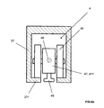
- FIG. 6 the carriage 4 of FIG. 2 in a particularly preferred embodiment, in which the holding unit 45 is connected to the fitting 111 on the sliding door 11 and the body 41 of the carriage 4 is provided on one or both sides with wheel axles 441 , on which running wheels 44 are held.
- FIG. 1 shows a displacement device 2 for an article of furniture 1 , which comprises a mounting bracket 21 , on which hinges 3 are provided, which serve for holding a separation element 11 (see FIG. 4 ).
- the mounting bracket 21 will typically be held in vertical alignment by means of a scissor assembly, as it is disclosed in [1].
- the displacement device 2 allows transferring the separation elements 11 into a door compartment 14 , which is delimited by an outer sidewall and by an intermediate wall 13 of the article of furniture 1 .
- the mounting brackets 21 is held by an inventive carriage 4 and guided along an upper rail 27 .
- the load of the separation elements 11 is absorbed by the carriage 4 , and thus reducing the load on the scissor assembly.
- the inventive carriage 4 which comprises the carriage body 41 with a carriage housing 411 , in which an adjustment device is located, will be described below more closely with reference to FIGS. 1 , 2 , and 3 .
- FIG. 2 shows the carriage 4 of FIG. 1 with opened carriage housing 411 , in which the elements of the adjustment device 45 , 451 , 452 as well as 46 and 47 are provided.
- FIG. 3 shows the carriage 4 of FIG. 2 in an exploded view.
- the carriage 4 comprises a carriage body 41 with a carriage housing 411 , in which an holding unit 45 is mounted so as to be displaceable in height.
- Said holding unit 45 consists of a vertically orientated holding bar 451 and a holding wedge 452 fixed to the lower side of the holding bar 451 .
- On the upper side of the holding bar 451 a bearing opening 453 is provided, into which a central axle 431 can be introduced, which pivotally holds a support lever 43 in the middle.
- the support lever 43 comprises on each of its two sides a receiving opening 432 , in which the axles 441 of running wheels 44 are held.
- the support lever 43 thus serves as a rocker element, which follows the inclination of the running rail 27 and distributes the load evenly on both running wheels 44 .
- the holding bar 451 is held in the housing 411 of the carriage body 41 between two guide beams 4114 so as to be vertically displaceable and projects outwards through a housing opening 4111 .
- the holding bar 453 is held by means of a bearing block 421 , which is arranged on the lid 42 of the carriage housing 411 .
- On the housing lid 42 receiving openings 422 for end screws 423 are provided, whereby said end screws 423 can be rotated in threaded bores 4113 in the carriage body 41 . After the fixing the holding bar 451 is thus held so as to be vertically displaceable.
- an adjusting screw 46 is provided in the carriage housing 411 , which adjusting screw 46 comprises at both ends a screw head 461 and between them a screw shank 462 with a thread.
- the two screw heads 461 are rotatably held in bearing openings 4112 , which are provided in sides of the carriage housing 411 lying opposite each other.
- the bearing openings 4112 lie at the same height and the adjusting screw 46 is thus orientated horizontally and at the same time perpendicularly to the displacement direction of the holding bar 451 .
- the screw shank 462 of the adjusting screw 46 is turned into a threaded channel 471 , which runs completely through an adjusting wedge 47 .
- the adjusting wedge 47 thereby lies above the holding wedge 452 , whereby two wedge faces inclined against the horizontal lie against each other as soon as the holding bar 451 is drawn upwards.
- the adjusting wedge 47 moves in horizontal direction from one side to the other of the carriage housing 411 , whereby the holding wedge 452 is displaced downwards or, under load, upwards.
- the height of the carriage body 41 and of the bracket 21 connected thereto with the aid of the mounting part 412 can be precisely set.
- the adjusting screw 46 can be manipulated from two sides of the housing 411 and thus also from the front side of the article of furniture 1 .
- the height is thereby set in such a way that the weight of the separation element 11 is preferably completely assumed by the carriage 4 and the separation element 11 is simultaneously held at the provided height.
- FIG. 4 shows the carriage 4 and is the mounting brackets 21 of FIG. 1 with the mounted separation elements 11 .
- the mounting part 412 which is connected to the carriage body 41 , has been inserted into a mounting channel 2111 provided in the mounting bracket 21 .
- Separation elements 11 i.e. the door of the article of furniture, is projecting frontally away from the article of furniture, so that it can either be transferred to the door compartment or be turned in order to close the article of furniture.
- the inventive carriage 4 with the height adjustment described can also be advantageously used with other devices. It is not thereby compulsory for the holding bar 451 to be connected via a pivotable support lever 43 to the running wheels.
- the support lever 43 can also be fixedly connected to the holding bar 451 .
- running wheels 44 or running rollers which can be provided in any number, can also be directly connected to the carriage body 41 , while the holding bar 451 is connected to a separation element 11 , for example a sliding door, and can hold this at an optionally adjustable height.
- the holding bar 451 can thereby be designed as desired.
- the holding bar can be formed as a thin hook, by means of which the fitting of a separation element 11 , e.g. a wooden panel or a glass panel, is detected.
- Screw connections between the carriage 4 and the fitting 111 of the separation element 11 as described for example in [4], U.S. Pat. No. 6,052,867, can thus be drastically simplified.
- the fitting connected to the separation element can be reduced in its dimensions to the minimum and no longer requires the mounting of movable parts such as screws.
- the holding bar as a screw, which is preferably rotatably connected to the holding wedge.
- a rough setting can be carried out and, with the aid of the adjusting screw, a fine setting can be carried out.
- a detent element is preferably provided in the carriage body, for example a locking screw, by means of which the screw-form holding bar can be fixed.
- a vertically extending groove is provided in the holding bar, into which groove the locking screw can be rotated in order to hold it in a rotationally secure way, in which it can be displaced merely vertically.
- the inventive carriage 4 can thus be connected in various ways to any desired separation elements 11 .
- the separation elements can be produced from any desired materials such as glass, metal, wood or plastic.
- FIG. 5 shows the carriage 4 of FIG. 2 with a mounting part 412 that is connected to a fitting 111 of a sliding door 11 .
- FIG. 6 shows the carriage 4 of FIG. 2 in a particularly preferred embodiment, in which the holding unit 45 comprises a connecting element 455 that is attached to the fitting 111 of the sliding door 11 .
- the connecting element 455 comprises the form of a screw head, which is coupled with the fitting 111 .
- the body 41 of the carriage 4 is on one side or on both sides provided with wheel axles 441 that hold a running wheel 44 each.
- the carriage 4 including the adjustment device provided in the carriage housing 411 , is completely integrated within the rail 27 .
- FIG. 6 a shows that any rail 27 can be used for the inventive carriages 4 .
- normally L-profiled rails 27 are used for carriages 4 that are provided with running wheels 44 on one side only.
- normally U-profiled rails 27 are used for carriages 4 that are provided with running wheels 44 on both sides.
- the running wheels 44 rolling on foot elements 271 of the rail 27 .
- the inventive carriage 4 can be used in various ways. Hence, it is pointed to the fact, that various further embodiments can the result by reversal of functions, such as kinematic reversal.
Applications Claiming Priority (3)
| Application Number | Priority Date | Filing Date | Title |
|---|---|---|---|
| EP09158984 | 2009-04-28 | ||
| EP09158984.6 | 2009-04-28 | ||
| EP09158984A EP2246509B1 (fr) | 2009-04-28 | 2009-04-28 | Dispositif de déplacement pour éléments de séparation maintenus de manière rotative et élément de mobilier |
Publications (2)
| Publication Number | Publication Date |
|---|---|
| US20100269291A1 US20100269291A1 (en) | 2010-10-28 |
| US8522398B2 true US8522398B2 (en) | 2013-09-03 |
Family
ID=41011865
Family Applications (2)
| Application Number | Title | Priority Date | Filing Date |
|---|---|---|---|
| US12/662,688 Active 2031-10-23 US8522398B2 (en) | 2009-04-28 | 2010-04-28 | Carriage for holding a separation element and separation element |
| US12/662,684 Active 2031-02-10 US8336972B2 (en) | 2009-04-28 | 2010-04-28 | Displacement device for pivotally held separation elements and article of furniture |
Family Applications After (1)
| Application Number | Title | Priority Date | Filing Date |
|---|---|---|---|
| US12/662,684 Active 2031-02-10 US8336972B2 (en) | 2009-04-28 | 2010-04-28 | Displacement device for pivotally held separation elements and article of furniture |
Country Status (10)
| Country | Link |
|---|---|
| US (2) | US8522398B2 (fr) |
| EP (3) | EP2527576B1 (fr) |
| JP (2) | JP5915825B2 (fr) |
| CN (2) | CN101876228B (fr) |
| AU (2) | AU2010201663B2 (fr) |
| CA (2) | CA2701247C (fr) |
| ES (3) | ES2513642T3 (fr) |
| NZ (2) | NZ584905A (fr) |
| PL (2) | PL2246509T3 (fr) |
| TW (2) | TWI494494B (fr) |
Cited By (16)
| Publication number | Priority date | Publication date | Assignee | Title |
|---|---|---|---|---|
| US20130160955A1 (en) * | 2010-07-06 | 2013-06-27 | Somfy Sas | Motorized carriage for a curtain and concealment facility comprising such a carriage |
| US20130333292A1 (en) * | 2012-05-14 | 2013-12-19 | Abp Beyerle Gmbh | Sliding door |
| US20140237769A1 (en) * | 2013-02-25 | 2014-08-28 | Anthony Innovations Pty, Ltd. | Roller Wheel Carriage and Bearing Assembly |
| US20150074942A1 (en) * | 2013-09-18 | 2015-03-19 | Hawa Ag | Adjustable mounting device for a sliding element and sliding device |
| US9009918B2 (en) | 2013-07-26 | 2015-04-21 | Hawa Ag | Adjustable carriage and shifting device |
| US20150211275A1 (en) * | 2014-01-28 | 2015-07-30 | Terno Scorrevoli Srl | Support bracket for sliding doors with side locking and adjustment |
| US9284761B2 (en) | 2012-12-05 | 2016-03-15 | Hawa Ag | Displacement device for slidable and turnable separation elements and functional entity |
| US20170231413A1 (en) * | 2014-08-19 | 2017-08-17 | Silent Gliss International Ag | Suspension Unit for a Curtain Device |
| US9976329B1 (en) * | 2017-05-05 | 2018-05-22 | Caldwell Manufacturing Company North America, LLC | Adjustable carriage assembly for suspending a panel |
| US9995073B2 (en) * | 2014-02-10 | 2018-06-12 | Dynamic Closures Corporation | Folding door trolley |
| US10323447B2 (en) * | 2017-03-23 | 2019-06-18 | Hawa Sliding Solutions Ag | Adjustable guide device for a sliding element |
| US11118386B2 (en) * | 2017-05-11 | 2021-09-14 | Julius Blum Gmbh | Guide carriage for the displaceable mounting of a furniture part |
| US11391076B2 (en) | 2017-05-11 | 2022-07-19 | Julius Blum Gmbh | Rail for guiding a carriage of a furniture door |
| US11781355B1 (en) * | 2022-06-06 | 2023-10-10 | Tracy Lammers | Roller assembly with side-accessed adjustment mechanism |
| US11879283B2 (en) | 2018-11-13 | 2024-01-23 | Julius Blum Gmbh | Arrangement for guiding a sliding door |
| US11913270B2 (en) | 2018-11-14 | 2024-02-27 | Julius Blum Gmbh | Guide system for guiding a movably mounted door leaf |
Families Citing this family (56)
| Publication number | Priority date | Publication date | Assignee | Title |
|---|---|---|---|---|
| EP2218858B1 (fr) * | 2009-02-15 | 2013-10-16 | Hawa Ag | Train de roulement pour un élément de séparation, élément de séparation et dispositif |
| IT1402815B1 (it) | 2010-12-03 | 2013-09-27 | Borrtoluzzi Lab S R L | Dispositivo per l'applicazione di porte a scomparsa laterale, particolarmente per mobili |
| US8850659B2 (en) * | 2011-11-03 | 2014-10-07 | K. Bradley Ewing | Top hung sliding panel apparatus and method |
| US8578558B2 (en) * | 2012-02-23 | 2013-11-12 | Sub-Zero, Inc. | Hinge support |
| CN102777094A (zh) * | 2012-06-19 | 2012-11-14 | 无锡市百顺机械厂 | 导向装置 |
| SI2685039T1 (sl) * | 2012-07-11 | 2020-01-31 | Hawa Sliding Solutions Ag | Vodilna naprava, tekalni mehanizem in tekalna tirnica |
| US9085924B2 (en) | 2012-12-04 | 2015-07-21 | Milgard Manufacturing Incorporated | Lift adjust sliding door roller |
| CA2799761C (fr) * | 2012-12-20 | 2019-06-11 | Fleurco Products Inc. | Systeme de butee de porte coulissante |
| AU2014208204B2 (en) * | 2013-08-09 | 2018-07-05 | Azuma Design Pty Limited | A roller assembly |
| DE102013223459A1 (de) * | 2013-08-19 | 2015-02-19 | Kl Megla Gmbh | Tür mit elektrischer Kontaktierung |
| CA2861977A1 (fr) * | 2013-09-06 | 2015-03-06 | Mark A. Johnson | Butoir de porte de douche |
| CN104563690A (zh) * | 2013-10-23 | 2015-04-29 | 天津海州科工贸有限公司 | 一种可调间隙的门与框构件 |
| CN104563691A (zh) * | 2013-10-23 | 2015-04-29 | 天津海州科工贸有限公司 | 一种机动车门与框体多向调整的机构 |
| EP2876233A1 (fr) * | 2013-11-21 | 2015-05-27 | Planet GDZ AG | Pêne dormant et système d'étanchéité de porte |
| EP2886762B1 (fr) * | 2013-12-20 | 2017-12-13 | Electrolux Appliances Aktiebolag | Charnière à bras multiples |
| RU2667139C2 (ru) | 2014-01-22 | 2018-09-14 | Кобленц С.п.А. | Регулируемый узел каретки для подвешивания разделительных элементов |
| US8925258B1 (en) * | 2014-01-27 | 2015-01-06 | Gregory Header | Wall and door panel adjustment device |
| US9440727B2 (en) * | 2014-07-11 | 2016-09-13 | B/E Aerospace, Inc. | Telescoping aircraft panel door |
| US9976336B2 (en) * | 2014-07-11 | 2018-05-22 | B/E Aerospace, Inc. | Telescoping aircraft panel door |
| JP7064804B2 (ja) * | 2014-09-24 | 2022-05-11 | ハワ スライディング ソリューションズ アーゲー | 摺動要素の調節可能取り付け装置、および摺動装置 |
| AT516567B1 (de) * | 2014-11-26 | 2018-01-15 | Blum Gmbh Julius | Anordnung aus einer Möbeltüre und einem Hohlraum |
| EP3029248B1 (fr) | 2014-12-02 | 2019-10-02 | Hawa Sliding Solutions AG | Dispositif de coulissement pour un élément de séparation et pièce de meuble |
| CN105003146A (zh) * | 2015-06-12 | 2015-10-28 | 佛山联升压铸科技有限公司 | 一种安全门滚轮的安装结构 |
| CN105098569B (zh) * | 2015-09-23 | 2018-05-08 | 江苏卓远激光科技有限公司 | 一种激光器电极板的浮动式安装结构 |
| JP6587885B2 (ja) * | 2015-09-30 | 2019-10-09 | アトムリビンテック株式会社 | 引戸の跳ね上がり抑制装置 |
| DE202015008693U1 (de) * | 2015-12-18 | 2017-03-21 | Grass Gmbh | Führungsvorrichtung zur Führung eines relativ zu einem Möbelkorpus bewegbaren Möbelteils |
| USD798220S1 (en) * | 2016-03-01 | 2017-09-26 | European Trailer Systems GmgH | Tarpaulin roller assembly for trucks |
| USD795157S1 (en) * | 2016-03-01 | 2017-08-22 | European Trailer Systems Gmbh | Tarpaulin roller assembly for trucks |
| US9894996B1 (en) * | 2016-10-31 | 2018-02-20 | Larry Mitchell Grela | Cabinet |
| IT201700081786A1 (it) * | 2017-07-19 | 2019-01-19 | Terno Scorrevoli S P A Unipersonale | Dispositivo di scorrimento per porte e ante di armadi provvisto di regolazioni multiple |
| CN107654145B (zh) * | 2017-10-30 | 2019-05-03 | 江苏彬飞冶金设备制造有限公司 | 一种密封专用的导轨滑轮 |
| CN111406143B (zh) * | 2017-11-28 | 2022-03-22 | 博尔托卢齐系统股份公司 | 用于家具扇页的伺服机构 |
| AU2017279738B1 (en) * | 2017-12-21 | 2018-08-30 | Assa Abloy New Zealand Limited | Multi panel components |
| US10914105B2 (en) * | 2018-05-01 | 2021-02-09 | Whirlpool Corporation | Cabinet door assembly for a household appliance |
| AT521133B1 (de) * | 2018-11-14 | 2019-11-15 | Blum Gmbh Julius | Führungssystem zur Führung eines bewegbar gelagerten Türflügels |
| CN111568159B (zh) * | 2019-02-18 | 2021-04-16 | 宁波方太厨具有限公司 | 一种面板可翻转的烹饪电器 |
| CN109914982A (zh) * | 2019-04-25 | 2019-06-21 | 韩建军 | 一种平移推拉门窗 |
| EP3980619B1 (fr) * | 2019-06-07 | 2023-09-13 | Hawa Sliding Solutions AG | Meuble comprenant une porte tenue par un dispositif de déplacement |
| CN110638228A (zh) * | 2019-10-10 | 2020-01-03 | 重庆电子工程职业学院 | 一种物联网家用鞋柜 |
| IT201900020904A1 (it) * | 2019-11-12 | 2021-05-12 | Metalglas Bonomi S R L | Sistema a pannelli mobili con dispositivo carrello |
| CN111075295B (zh) * | 2019-12-13 | 2022-04-15 | 广东坚朗五金制品股份有限公司 | 轮滑机构及移轮门窗 |
| AT17257U1 (de) * | 2019-12-19 | 2021-10-15 | Blum Gmbh Julius | Verfahren zur Montage einer Führungsanordnung für ein bewegbares Möbelteil |
| CN112796601A (zh) * | 2020-12-31 | 2021-05-14 | 中山市福瑞卫浴设备有限公司 | 折叠式移门连接件及淋浴房门 |
| DE202021004263U1 (de) | 2021-04-28 | 2023-05-08 | Hawa Sliding Solutions Ag | Verschiebevorrichtung für eine Schiebetür, Anordnung und Antriebsvorrichtung |
| EP4083359A1 (fr) | 2021-04-28 | 2022-11-02 | Hawa Sliding Solutions AG | Dispositif coulissant pour une porte coulissante et meuble |
| DE202021004262U1 (de) | 2021-04-28 | 2023-05-05 | Hawa Sliding Solutions Ag | Faltvorrichtung für eine Falttür und Möbel mit einer Falttür |
| EP4083361A1 (fr) | 2021-04-28 | 2022-11-02 | Hawa Sliding Solutions AG | Dispositif pliant pour une porte pliante et mobilier pourvu de porte pliante |
| EP4083362A1 (fr) | 2021-04-28 | 2022-11-02 | Hawa Sliding Solutions AG | Dispositif de tirage pour une porte pliante et meuble doté d'une porte pliante |
| EP4083363A1 (fr) * | 2021-04-28 | 2022-11-02 | Hawa Sliding Solutions AG | Dispositif coulissant pour porte coulissante, agencement et dispositif d'entraînement |
| CN114310929B (zh) * | 2021-11-30 | 2023-10-24 | 杭州申昊科技股份有限公司 | 一种轨道巡检机器人的行走机构 |
| EP4286633A1 (fr) | 2022-06-01 | 2023-12-06 | Hawa Sliding Solutions AG | Dispositif coulissant doté d'un profilé de montage et unité fonctionnelle |
| EP4286631A1 (fr) | 2022-06-01 | 2023-12-06 | Hawa Sliding Solutions AG | Dispositif coulissant doté d'un profilé de montage, procédé d'installation et unité fonctionnelle |
| WO2023232440A1 (fr) | 2022-06-01 | 2023-12-07 | Hawa Sliding Solutions Ag | Dispositif de coulissement comprenant un élément de montage profilé, et unité fonctionnelle |
| EP4286632A1 (fr) | 2022-06-01 | 2023-12-06 | Hawa Sliding Solutions AG | Unité fonctionnelle dotée d'un compartiment de porte pour une porte maintenue coulissante |
| EP4299867A1 (fr) * | 2022-07-01 | 2024-01-03 | Hawa Sliding Solutions AG | Charnière de porte pliante et unité fonctionnelle dotée d'une porte pliante |
| CN115405182A (zh) * | 2022-09-29 | 2022-11-29 | 佛山市南海伊盾家居科技有限公司 | 一种隐轨推拉门 |
Citations (16)
| Publication number | Priority date | Publication date | Assignee | Title |
|---|---|---|---|---|
| US524609A (en) * | 1894-08-14 | Theodore c | ||
| US956025A (en) * | 1909-06-30 | 1910-04-26 | Coburn Trolley Track Mfg Company | Door-hanger. |
| CA1040933A (fr) | 1975-09-08 | 1978-10-24 | Joseph F. Steigerwald | Galet pour fermeture coulissante |
| US5018306A (en) * | 1989-05-22 | 1991-05-28 | Ferco International | Bearing device for sliding leaf of doors, windows or the like |
| US5149180A (en) | 1989-03-14 | 1992-09-22 | Karl Haab | Article of furniture with a door slidable into door compartment |
| US5791089A (en) * | 1996-04-10 | 1998-08-11 | Ferco International | Rolling device for a sliding leaf of a door window or the like |
| US5860189A (en) * | 1997-03-06 | 1999-01-19 | An; Tae-Heup | Door wheel |
| US6021547A (en) * | 1997-05-20 | 2000-02-08 | Anthony Bearings Pty Ltd. | Door adjustment mechanism |
| US6052867A (en) | 1997-06-24 | 2000-04-25 | Hawa Ag | Device for connecting a displaceable element to a guide device |
| KR20020011199A (ko) | 2000-08-01 | 2002-02-08 | 추두련 | 걸이식 미닫이 문 및 매달린 바퀴 |
| US6418588B1 (en) | 1999-04-27 | 2002-07-16 | Hawa Ag | Suspension device |
| EP1460225A1 (fr) | 2003-03-21 | 2004-09-22 | Eku Ag | Chariot pour une porte coulissante |
| US20050011041A1 (en) * | 2003-06-18 | 2005-01-20 | Ness John T. | Precision machined roller wheel assembly |
| US20060230684A1 (en) * | 2005-04-13 | 2006-10-19 | Craig Poole | Pocket door trolly assembly |
| CN101063392A (zh) | 2006-04-28 | 2007-10-31 | 李根浚 | 拉门用滚轮 |
| US7712258B2 (en) * | 2004-04-22 | 2010-05-11 | K. Bradley Ewing | Suspension and sill system for sliding members |
Family Cites Families (41)
| Publication number | Priority date | Publication date | Assignee | Title |
|---|---|---|---|---|
| US972412A (en) * | 1909-08-04 | 1910-10-11 | Maurice Taussig | Disappearing door. |
| US1606587A (en) * | 1925-09-25 | 1926-11-09 | Walter H May | Display rack |
| CH384805A (de) * | 1960-12-30 | 1965-02-26 | Erismann Paul | Schrank mit einer schwenkbaren Türe und wenigstens einer Schublade |
| CH436019A (de) * | 1963-08-30 | 1967-05-15 | Asquini Valentino | Schnappscharnier, insbesondere für Möbel |
| US4186972A (en) * | 1978-05-26 | 1980-02-05 | Hagen Magnus F | Linearly movable stabilizer for slidable structures |
| DE2847578A1 (de) | 1978-11-02 | 1980-05-08 | Schock Metallwerk | Fuehrungsvorrichtung fuer an einem traeger linear verstellbar angeordnete gegenstaende, insbesondere zur parallelverstellung von moebeleinschueben |
| DE7832884U1 (de) | 1978-11-06 | 1980-01-03 | Baus, Heinz Georg, Thun (Schweiz) | Eckverbinder fuer den rahmen einer verschiebbaren wandtafel einer schiebetrennwand |
| DE2947153A1 (de) * | 1979-11-22 | 1981-06-04 | Alfred Grass GmbH Metallwarenfabrik, 6973 Höchst, Vorarlberg | Tuerscharnier mit schliessdruckvorrichtung |
| DE3218375C2 (de) * | 1982-05-15 | 1985-12-12 | Karl Lautenschläger KG, Möbelbeschlagfabrik, 6107 Reinheim | Eingelenk-Möbelscharnier |
| DE3338146C2 (de) | 1983-01-14 | 1985-03-07 | Heinz Georg Hünibach Thun Baus | Duschabtrennung |
| AT381136B (de) * | 1984-05-07 | 1986-08-25 | Blum Gmbh Julius | Scharnier |
| CH670555A5 (fr) * | 1986-07-02 | 1989-06-30 | Karl Haab | |
| JPH056367Y2 (fr) * | 1987-11-09 | 1993-02-18 | ||
| US4821375A (en) * | 1988-01-29 | 1989-04-18 | Viking Metal Cabinet Co., Inc. | Recessing hinge mechanism |
| NL8800936A (nl) * | 1988-04-11 | 1989-11-01 | Pella Bv | Scheidingswand, bestaande uit scharnierbaar aan elkaar gekoppelde dubbelwandige panelen. |
| US4987640A (en) * | 1989-03-02 | 1991-01-29 | Hu Lin Industrial Co., Ltd. | Super-thin hinge with resiliently biased catch |
| DE3914103A1 (de) | 1989-04-28 | 1990-10-31 | Lautenschlaeger Kg Karl | Schnaepperscharnier |
| DE3920141C1 (fr) * | 1989-06-20 | 1990-08-16 | Arturo Salice S.P.A., Novedrate, Como, It | |
| JPH0411181A (ja) * | 1990-04-28 | 1992-01-16 | Nissan Motor Co Ltd | 自動車用フードヒンジ構造 |
| DE4217640C2 (de) * | 1992-05-28 | 1994-05-26 | Bembnowski Jorge | Scharnier, insbesondere für Möbeltüren |
| US5395165A (en) * | 1993-03-25 | 1995-03-07 | Hafele America Co. | Suspension system for pocket-type doors |
| JPH0682356U (ja) * | 1993-05-14 | 1994-11-25 | 松下電工株式会社 | 戸のランナーの高さ調整装置 |
| JPH0921268A (ja) | 1995-07-07 | 1997-01-21 | Yogou Sumikin Sangyo Kk | 引戸吊具 |
| GR960100122A (el) * | 1996-04-11 | 1997-12-31 | Συστημα αναρτησης συρομενης πορτας με μηχανισμο ρυθμισης υψους και κλισης της πορτας. | |
| EP0909864A3 (fr) | 1997-10-17 | 1999-05-06 | Julius Blum Gesellschaft m.b.H. | Charnière |
| JP3909961B2 (ja) * | 1998-08-19 | 2007-04-25 | 不二サッシ株式会社 | 吊車の高さ位置調節装置 |
| AT407416B (de) | 1999-04-28 | 2001-03-26 | Blum Gmbh Julius | Scharnier mit einem scharnierarm |
| JP2002081258A (ja) * | 2000-09-07 | 2002-03-22 | Meiko:Kk | 吊り車型ランナ装置 |
| EP1231346B1 (fr) * | 2001-02-13 | 2012-02-01 | Liebherr-Hausgeräte Ochsenhausen GmbH | Articulation à charnière |
| JP2003106034A (ja) * | 2001-10-02 | 2003-04-09 | Kuriki Manufacture Co Ltd | 吊戸用吊車 |
| AT5924U1 (de) * | 2001-11-19 | 2003-01-27 | Blum Gmbh Julius | Scharnier, vorzugsweise einachsscharnier |
| JP2003278440A (ja) * | 2002-03-20 | 2003-10-02 | Inoue Kanamono Kk | アーム式ヒンジ |
| TWM254942U (en) * | 2004-04-23 | 2005-01-11 | Guang-Tai Ge | Structure of cabinet hinge with continuous slow movement functions |
| ITTO20040439A1 (it) * | 2004-06-28 | 2004-09-28 | Savio Spa | Gruppo di articolazione superiore per serramenti apribili ad anta e a ribalta |
| TWM303254U (en) * | 2006-06-28 | 2006-12-21 | Auspice Internat Co Ltd G | Dual-purpose upper rail set for glass door |
| FR2903446B1 (fr) | 2006-07-07 | 2009-10-30 | S E E D Sarl | Dispositif porte-roue pour panneau coulissant,en particulier de porte |
| WO2008024469A2 (fr) * | 2006-08-25 | 2008-02-28 | Terry Moseley | Charnière avec angle d'ouverture maximal ajustable |
| TWM313711U (en) * | 2006-10-23 | 2007-06-11 | Good Credit Corp | Structure of rail connection of sliding door |
| JP4750673B2 (ja) * | 2006-11-01 | 2011-08-17 | 信行 坪井 | 引き戸の吊下げ支持装置 |
| JP4512102B2 (ja) * | 2006-11-01 | 2010-07-28 | 進 早雲 | 調整戸車及びこれを備えた戸 |
| ES2919854T3 (es) * | 2009-10-26 | 2022-07-28 | Panoramic Doors Llc | Estructura de puerta corredera con puertas correderas y puertas pivotantes |
-
2009
- 2009-04-28 PL PL09158984T patent/PL2246509T3/pl unknown
- 2009-04-28 ES ES12179325.1T patent/ES2513642T3/es active Active
- 2009-04-28 ES ES09158984T patent/ES2397458T3/es active Active
- 2009-04-28 EP EP12179325.1A patent/EP2527576B1/fr not_active Revoked
- 2009-04-28 EP EP09158984A patent/EP2246509B1/fr active Active
-
2010
- 2010-04-19 ES ES10160247.2T patent/ES2563727T3/es active Active
- 2010-04-19 EP EP10160247.2A patent/EP2248976B1/fr active Active
- 2010-04-19 PL PL10160247T patent/PL2248976T3/pl unknown
- 2010-04-20 CA CA2701247A patent/CA2701247C/fr active Active
- 2010-04-20 CA CA2701263A patent/CA2701263C/fr active Active
- 2010-04-21 JP JP2010098228A patent/JP5915825B2/ja active Active
- 2010-04-21 JP JP2010098225A patent/JP5783483B2/ja active Active
- 2010-04-26 NZ NZ584905A patent/NZ584905A/en unknown
- 2010-04-26 TW TW099113003A patent/TWI494494B/zh active
- 2010-04-26 TW TW099113004A patent/TWI494496B/zh active
- 2010-04-26 NZ NZ584904A patent/NZ584904A/en unknown
- 2010-04-27 CN CN201010170524.7A patent/CN101876228B/zh active Active
- 2010-04-27 AU AU2010201663A patent/AU2010201663B2/en active Active
- 2010-04-27 CN CN201010170405.1A patent/CN101876229B/zh active Active
- 2010-04-27 AU AU2010201662A patent/AU2010201662B2/en active Active
- 2010-04-28 US US12/662,688 patent/US8522398B2/en active Active
- 2010-04-28 US US12/662,684 patent/US8336972B2/en active Active
Patent Citations (16)
| Publication number | Priority date | Publication date | Assignee | Title |
|---|---|---|---|---|
| US524609A (en) * | 1894-08-14 | Theodore c | ||
| US956025A (en) * | 1909-06-30 | 1910-04-26 | Coburn Trolley Track Mfg Company | Door-hanger. |
| CA1040933A (fr) | 1975-09-08 | 1978-10-24 | Joseph F. Steigerwald | Galet pour fermeture coulissante |
| US5149180A (en) | 1989-03-14 | 1992-09-22 | Karl Haab | Article of furniture with a door slidable into door compartment |
| US5018306A (en) * | 1989-05-22 | 1991-05-28 | Ferco International | Bearing device for sliding leaf of doors, windows or the like |
| US5791089A (en) * | 1996-04-10 | 1998-08-11 | Ferco International | Rolling device for a sliding leaf of a door window or the like |
| US5860189A (en) * | 1997-03-06 | 1999-01-19 | An; Tae-Heup | Door wheel |
| US6021547A (en) * | 1997-05-20 | 2000-02-08 | Anthony Bearings Pty Ltd. | Door adjustment mechanism |
| US6052867A (en) | 1997-06-24 | 2000-04-25 | Hawa Ag | Device for connecting a displaceable element to a guide device |
| US6418588B1 (en) | 1999-04-27 | 2002-07-16 | Hawa Ag | Suspension device |
| KR20020011199A (ko) | 2000-08-01 | 2002-02-08 | 추두련 | 걸이식 미닫이 문 및 매달린 바퀴 |
| EP1460225A1 (fr) | 2003-03-21 | 2004-09-22 | Eku Ag | Chariot pour une porte coulissante |
| US20050011041A1 (en) * | 2003-06-18 | 2005-01-20 | Ness John T. | Precision machined roller wheel assembly |
| US7712258B2 (en) * | 2004-04-22 | 2010-05-11 | K. Bradley Ewing | Suspension and sill system for sliding members |
| US20060230684A1 (en) * | 2005-04-13 | 2006-10-19 | Craig Poole | Pocket door trolly assembly |
| CN101063392A (zh) | 2006-04-28 | 2007-10-31 | 李根浚 | 拉门用滚轮 |
Non-Patent Citations (1)
| Title |
|---|
| Examination Report on New Zealand Patent Application No. 584905, mailed on May 4, 2010. |
Cited By (23)
| Publication number | Priority date | Publication date | Assignee | Title |
|---|---|---|---|---|
| US20130160955A1 (en) * | 2010-07-06 | 2013-06-27 | Somfy Sas | Motorized carriage for a curtain and concealment facility comprising such a carriage |
| US9101239B2 (en) * | 2010-07-06 | 2015-08-11 | Somfy Sas | Motorized carriage for a curtain and concealment facility comprising such a carriage |
| US20130333292A1 (en) * | 2012-05-14 | 2013-12-19 | Abp Beyerle Gmbh | Sliding door |
| US9027283B2 (en) * | 2012-05-14 | 2015-05-12 | Abp Beyerle Gmbh | Sliding door |
| US9624705B2 (en) * | 2012-12-05 | 2017-04-18 | Hawa Ag | Displacement device for slidable and turnable separation elements and functional entity |
| US20160201368A1 (en) * | 2012-12-05 | 2016-07-14 | Hawa Ag | Displacement device for slidable and turnable separation elements and functional entity |
| US9284761B2 (en) | 2012-12-05 | 2016-03-15 | Hawa Ag | Displacement device for slidable and turnable separation elements and functional entity |
| US20140237769A1 (en) * | 2013-02-25 | 2014-08-28 | Anthony Innovations Pty, Ltd. | Roller Wheel Carriage and Bearing Assembly |
| US8984716B2 (en) * | 2013-02-25 | 2015-03-24 | Anthony Innovations Pty Ltd. | Roller wheel carriage and bearing assembly |
| US9009918B2 (en) | 2013-07-26 | 2015-04-21 | Hawa Ag | Adjustable carriage and shifting device |
| US9341011B2 (en) * | 2013-09-18 | 2016-05-17 | Hawa Ag | Adjustable mounting device for a sliding element and sliding device |
| US20150074942A1 (en) * | 2013-09-18 | 2015-03-19 | Hawa Ag | Adjustable mounting device for a sliding element and sliding device |
| US9376848B2 (en) * | 2014-01-28 | 2016-06-28 | Terno Scorrevoli Srl | Support bracket for sliding doors with side locking and adjustment |
| US20150211275A1 (en) * | 2014-01-28 | 2015-07-30 | Terno Scorrevoli Srl | Support bracket for sliding doors with side locking and adjustment |
| US9995073B2 (en) * | 2014-02-10 | 2018-06-12 | Dynamic Closures Corporation | Folding door trolley |
| US20170231413A1 (en) * | 2014-08-19 | 2017-08-17 | Silent Gliss International Ag | Suspension Unit for a Curtain Device |
| US10323447B2 (en) * | 2017-03-23 | 2019-06-18 | Hawa Sliding Solutions Ag | Adjustable guide device for a sliding element |
| US9976329B1 (en) * | 2017-05-05 | 2018-05-22 | Caldwell Manufacturing Company North America, LLC | Adjustable carriage assembly for suspending a panel |
| US11118386B2 (en) * | 2017-05-11 | 2021-09-14 | Julius Blum Gmbh | Guide carriage for the displaceable mounting of a furniture part |
| US11391076B2 (en) | 2017-05-11 | 2022-07-19 | Julius Blum Gmbh | Rail for guiding a carriage of a furniture door |
| US11879283B2 (en) | 2018-11-13 | 2024-01-23 | Julius Blum Gmbh | Arrangement for guiding a sliding door |
| US11913270B2 (en) | 2018-11-14 | 2024-02-27 | Julius Blum Gmbh | Guide system for guiding a movably mounted door leaf |
| US11781355B1 (en) * | 2022-06-06 | 2023-10-10 | Tracy Lammers | Roller assembly with side-accessed adjustment mechanism |
Also Published As
Similar Documents
| Publication | Publication Date | Title |
|---|---|---|
| US8522398B2 (en) | Carriage for holding a separation element and separation element | |
| US7891052B2 (en) | Device with a carriage for holding panels and a separation element | |
| CA2331459C (fr) | Dispositif tampon | |
| US10794100B2 (en) | Hinged bottom roller assembly and counterbalance mechanism for overhead door | |
| US8695165B2 (en) | Bogey assembly | |
| US8413299B2 (en) | Hinge for door or window | |
| GB2284234A (en) | Adjustable pivot for mounting glass doors | |
| US5121976A (en) | Furniture article with a door slidable into door compartment | |
| WO1994013915A1 (fr) | Ensemble de montage pour la suspension d'une porte vitree coulissante | |
| US4773465A (en) | Sliding door with folding panel | |
| GB2313405A (en) | Adjuster for a vent hinge | |
| US10982476B1 (en) | Support attachments for a door and a door frame | |
| JPH0635104Y2 (ja) | 間仕切り | |
| JP3160669B2 (ja) | 引戸のガイド装置 | |
| AU2014221269B2 (en) | Bogey assembly | |
| HU216613B (hu) | Billenőajtó | |
| GB2404687A (en) | Door assembly for a shower enclosure |
Legal Events
| Date | Code | Title | Description |
|---|---|---|---|
| AS | Assignment |
Owner name: HAWA AG, SWITZERLAND Free format text: ASSIGNMENT OF ASSIGNORS INTEREST;ASSIGNORS:HAAB, GREGOR;FREI, MARTIN;STUTZ, ALFRED;REEL/FRAME:024427/0146 Effective date: 20100503 |
|
| FEPP | Fee payment procedure |
Free format text: PAYOR NUMBER ASSIGNED (ORIGINAL EVENT CODE: ASPN); ENTITY STATUS OF PATENT OWNER: SMALL ENTITY |
|
| STCF | Information on status: patent grant |
Free format text: PATENTED CASE |
|
| FPAY | Fee payment |
Year of fee payment: 4 |
|
| MAFP | Maintenance fee payment |
Free format text: PAYMENT OF MAINTENANCE FEE, 8TH YR, SMALL ENTITY (ORIGINAL EVENT CODE: M2552); ENTITY STATUS OF PATENT OWNER: SMALL ENTITY Year of fee payment: 8 |