EP4286631A1 - Dispositif coulissant doté d'un profilé de montage, procédé d'installation et unité fonctionnelle - Google Patents
Dispositif coulissant doté d'un profilé de montage, procédé d'installation et unité fonctionnelle Download PDFInfo
- Publication number
- EP4286631A1 EP4286631A1 EP22176723.9A EP22176723A EP4286631A1 EP 4286631 A1 EP4286631 A1 EP 4286631A1 EP 22176723 A EP22176723 A EP 22176723A EP 4286631 A1 EP4286631 A1 EP 4286631A1
- Authority
- EP
- European Patent Office
- Prior art keywords
- carriage
- cable connection
- profile
- mounting profile
- drive
- Prior art date
- Legal status (The legal status is an assumption and is not a legal conclusion. Google has not performed a legal analysis and makes no representation as to the accuracy of the status listed.)
- Pending
Links
- 238000006073 displacement reaction Methods 0.000 title claims abstract description 124
- 238000009434 installation Methods 0.000 title claims abstract description 27
- 238000000034 method Methods 0.000 title claims description 9
- 238000013016 damping Methods 0.000 description 9
- 230000008878 coupling Effects 0.000 description 7
- 238000010168 coupling process Methods 0.000 description 7
- 238000005859 coupling reaction Methods 0.000 description 7
- 238000005192 partition Methods 0.000 description 7
- 238000012423 maintenance Methods 0.000 description 4
- 125000006850 spacer group Chemical group 0.000 description 4
- 230000005540 biological transmission Effects 0.000 description 3
- 238000013461 design Methods 0.000 description 3
- 238000005516 engineering process Methods 0.000 description 3
- 239000002184 metal Substances 0.000 description 3
- 238000003825 pressing Methods 0.000 description 3
- 238000011900 installation process Methods 0.000 description 2
- 229910000831 Steel Inorganic materials 0.000 description 1
- 230000001133 acceleration Effects 0.000 description 1
- 230000008859 change Effects 0.000 description 1
- 239000003086 colorant Substances 0.000 description 1
- 238000004040 coloring Methods 0.000 description 1
- 230000000295 complement effect Effects 0.000 description 1
- 238000012937 correction Methods 0.000 description 1
- 230000000694 effects Effects 0.000 description 1
- 230000004048 modification Effects 0.000 description 1
- 238000012986 modification Methods 0.000 description 1
- 239000010970 precious metal Substances 0.000 description 1
- 230000036316 preload Effects 0.000 description 1
- 230000008569 process Effects 0.000 description 1
- 238000005096 rolling process Methods 0.000 description 1
- 238000004904 shortening Methods 0.000 description 1
- 239000010959 steel Substances 0.000 description 1
- 238000012360 testing method Methods 0.000 description 1
Images


Classifications
-
- E—FIXED CONSTRUCTIONS
- E05—LOCKS; KEYS; WINDOW OR DOOR FITTINGS; SAFES
- E05D—HINGES OR SUSPENSION DEVICES FOR DOORS, WINDOWS OR WINGS
- E05D15/00—Suspension arrangements for wings
- E05D15/26—Suspension arrangements for wings for folding wings
-
- E—FIXED CONSTRUCTIONS
- E05—LOCKS; KEYS; WINDOW OR DOOR FITTINGS; SAFES
- E05D—HINGES OR SUSPENSION DEVICES FOR DOORS, WINDOWS OR WINGS
- E05D15/00—Suspension arrangements for wings
- E05D15/26—Suspension arrangements for wings for folding wings
- E05D15/264—Suspension arrangements for wings for folding wings for bi-fold wings
-
- E—FIXED CONSTRUCTIONS
- E05—LOCKS; KEYS; WINDOW OR DOOR FITTINGS; SAFES
- E05D—HINGES OR SUSPENSION DEVICES FOR DOORS, WINDOWS OR WINGS
- E05D15/00—Suspension arrangements for wings
- E05D15/56—Suspension arrangements for wings with successive different movements
- E05D15/58—Suspension arrangements for wings with successive different movements with both swinging and sliding movements
-
- E—FIXED CONSTRUCTIONS
- E05—LOCKS; KEYS; WINDOW OR DOOR FITTINGS; SAFES
- E05Y—INDEXING SCHEME ASSOCIATED WITH SUBCLASSES E05D AND E05F, RELATING TO CONSTRUCTION ELEMENTS, ELECTRIC CONTROL, POWER SUPPLY, POWER SIGNAL OR TRANSMISSION, USER INTERFACES, MOUNTING OR COUPLING, DETAILS, ACCESSORIES, AUXILIARY OPERATIONS NOT OTHERWISE PROVIDED FOR, APPLICATION THEREOF
- E05Y2201/00—Constructional elements; Accessories therefor
- E05Y2201/40—Motors; Magnets; Springs; Weights; Accessories therefor
- E05Y2201/47—Springs
- E05Y2201/488—Traction springs
-
- E—FIXED CONSTRUCTIONS
- E05—LOCKS; KEYS; WINDOW OR DOOR FITTINGS; SAFES
- E05Y—INDEXING SCHEME ASSOCIATED WITH SUBCLASSES E05D AND E05F, RELATING TO CONSTRUCTION ELEMENTS, ELECTRIC CONTROL, POWER SUPPLY, POWER SIGNAL OR TRANSMISSION, USER INTERFACES, MOUNTING OR COUPLING, DETAILS, ACCESSORIES, AUXILIARY OPERATIONS NOT OTHERWISE PROVIDED FOR, APPLICATION THEREOF
- E05Y2201/00—Constructional elements; Accessories therefor
- E05Y2201/60—Suspension or transmission members; Accessories therefor
- E05Y2201/606—Accessories therefor
- E05Y2201/62—Synchronisation of suspension or transmission members
-
- E—FIXED CONSTRUCTIONS
- E05—LOCKS; KEYS; WINDOW OR DOOR FITTINGS; SAFES
- E05Y—INDEXING SCHEME ASSOCIATED WITH SUBCLASSES E05D AND E05F, RELATING TO CONSTRUCTION ELEMENTS, ELECTRIC CONTROL, POWER SUPPLY, POWER SIGNAL OR TRANSMISSION, USER INTERFACES, MOUNTING OR COUPLING, DETAILS, ACCESSORIES, AUXILIARY OPERATIONS NOT OTHERWISE PROVIDED FOR, APPLICATION THEREOF
- E05Y2201/00—Constructional elements; Accessories therefor
- E05Y2201/60—Suspension or transmission members; Accessories therefor
- E05Y2201/622—Suspension or transmission members elements
- E05Y2201/644—Flexible elongated pulling elements
- E05Y2201/654—Cables
-
- E—FIXED CONSTRUCTIONS
- E05—LOCKS; KEYS; WINDOW OR DOOR FITTINGS; SAFES
- E05Y—INDEXING SCHEME ASSOCIATED WITH SUBCLASSES E05D AND E05F, RELATING TO CONSTRUCTION ELEMENTS, ELECTRIC CONTROL, POWER SUPPLY, POWER SIGNAL OR TRANSMISSION, USER INTERFACES, MOUNTING OR COUPLING, DETAILS, ACCESSORIES, AUXILIARY OPERATIONS NOT OTHERWISE PROVIDED FOR, APPLICATION THEREOF
- E05Y2201/00—Constructional elements; Accessories therefor
- E05Y2201/60—Suspension or transmission members; Accessories therefor
- E05Y2201/622—Suspension or transmission members elements
- E05Y2201/658—Members cooperating with flexible elongated pulling elements
- E05Y2201/672—Tensioners, tension sensors
-
- E—FIXED CONSTRUCTIONS
- E05—LOCKS; KEYS; WINDOW OR DOOR FITTINGS; SAFES
- E05Y—INDEXING SCHEME ASSOCIATED WITH SUBCLASSES E05D AND E05F, RELATING TO CONSTRUCTION ELEMENTS, ELECTRIC CONTROL, POWER SUPPLY, POWER SIGNAL OR TRANSMISSION, USER INTERFACES, MOUNTING OR COUPLING, DETAILS, ACCESSORIES, AUXILIARY OPERATIONS NOT OTHERWISE PROVIDED FOR, APPLICATION THEREOF
- E05Y2900/00—Application of doors, windows, wings or fittings thereof
- E05Y2900/20—Application of doors, windows, wings or fittings thereof for furniture, e.g. cabinets
- E05Y2900/212—Doors disappearing in pockets in the furniture body
Definitions
- the invention relates to a displacement device with a mounting profile, which is connected to a one-piece or multi-part door, possibly a folding sliding door, vertically aligned and preferably automatically displaceable within a door compartment, a functional unit, in particular a piece of furniture or a room unit, with at least one displacement device, and a method for installing the displacement device within the functional unit.
- one-piece or multi-part doors are often used, which are moved into a door compartment of the functional unit after the opening has been released in order not to appear disruptive.
- the US8336972B2 discloses a piece of furniture with a displacement device, by means of which a mounting profile connected to a one-piece door can be displaced within a door compartment.
- the displacement device comprises a holding device in the form of a scissor cross, by means of which the mounting profile is held displaceably in a vertical orientation.
- the displacement device also includes running rails along which the mounting profile is slidably mounted by means of drives.
- the US9284761B2 discloses a piece of furniture with a displacement device, by means of which a mounting profile connected to a folding sliding door can be displaced within a door compartment.
- the folding sliding door comprises two door elements, of which the first door element is connected at the back by stop hinges to the mounting profile and at the front by door hinges to the back of the second door element, which is connected at the front to a drive which is displaceable along a running rail, the two aligned perpendicular to each other and has rail sections connected to one another by a curve section, of which a first rail section runs into the door compartment and a second rail section runs along the front of the piece of furniture.
- Displacement devices are also known in which a mounting profile connected to a sliding door can be automatically moved within a door compartment by means of a drive device.
- the DE2045763A1 discloses a piece of furniture with a displacement device with a scissor cross, the scissor arms of which are connected to one another by a spring in order to automatically pull a mounting profile held by the scissor cross and connected to a door into a door compartment or eject it from the door compartment.
- the scissor cross takes up a relatively large amount of space and is typically adapted to the dimensions of the respective door compartment.
- the US10227806B2 discloses a further displacement device with a control cam, by means of which a mounting profile connected to a door can be automatically moved within a door compartment.
- the drive devices and the other elements of the displacement devices must therefore be adapted to one another and are therefore subject to significant restrictions. It should be noted that there is usually little space within the door compartment, which may be intended to accommodate more than one door element, which is why the restrictions when integrating the drive device into the displacement device are particularly critical.
- the EP1394349A1 discloses a displacement device with a displaceably mounted mounting profile, which is held perpendicular to the direction of displacement by means of a holding device with two metal cables.
- the mounting profile is provided with two lower running wheels at the lower end and two upper running wheels at the upper end, which are intended for rolling on an upper and a lower guide rail.
- the first metal cable is guided clockwise around the associated upper impeller and counterclockwise around the associated lower impeller and is held and tensioned on both sides by means of cable connection devices which are arranged on the front and rear of the displacement device.
- the second Metal cable is guided counterclockwise around the assigned upper impeller and clockwise around the assigned lower impeller and is held and tensioned on both sides by means of cable connection devices which are arranged on the front and back of the displacement device.
- the disadvantage of this device is that the function of the holding device depends largely on the adjustment of the rope tensions. If the rope tensions are not set correctly, the mounting profile may not be held correctly or blockages may occur. It should also be noted that installations of the displacement device are carried out by different installers at the installation site. This results in different settings, which impair the function of the displacement device and result in maintenance work.
- the present invention is therefore based on the object of creating an improved displacement device, by means of which a mounting profile, which is connected or connectable to a one-piece or multi-part door, can be displaced vertically aligned within a door compartment of a functional unit, a piece of furniture or a room unit. Furthermore, a method for installing the displacement device must be specified. Furthermore, a functional unit, a piece of furniture or a room unit, is to be created with at least one improved displacement device, by means of which a mounting profile connected to a door, possibly a folding sliding door, can be advantageously displaced within a door compartment of the functional unit.
- the displacement device should have a compact structure and be easy to assemble and take up little space, so that a lot of space can be kept free within the door compartment of the functional unit and the door compartment can be realized with reduced dimensions.
- the displacement device should be easily and precisely adjustable so that the displacement device is always optimally adjusted, regardless of the installer.
- the displacement device should function reliably even in the event of undesirable forces and should not be exposed to any loads that could cause damage.
- the displacement device should be robust and resilient. Maintenance work and readjustments should be largely avoided, even under high stress and strain.
- the mounting profile of the displacement device should be able to be moved automatically within the door compartment, so that a mounted door is automatically retracted into the door compartment or automatically ejected from the door compartment.
- the displacement device which is intended for installation in a door compartment of a functional unit, comprises a rod-shaped mounting profile, which is held vertically aligned by a holding device and is displaceable between a first end position and a second end position of a travel path and is connected or connectable to a one-piece or multi-part door by stop hinges is.
- the second rear cable connection device comprises a second tensioning device with a second connection carriage, which on the one hand is connected to the associated second tether and which, on the other hand, is connected by a second tension spring to a second tension carriage, into which a stationary second tensioning screw is screwed, by means of which the second pulling carriage and the second connecting carriage can be displaced relative to one another within a second bearing profile along the longitudinal axis of the latter;
- the first front cable connection device comprises a first adjusting device with a first adjusting slide, which on the one hand is connected to the fixed first tether and which, on the other hand, cooperates with a stationary adjusting screw which is rotatably held in the first adjusting slide.
- the two retaining cables of the holding device for example steel cables, which may be coated with precious metal and/or plastic, always hold the mounting profile in a perpendicular orientation to the guide rails during displacement within the door compartment.
- a kinematic reversal or a mirroring of the device parts described is possible.
- one of the retaining ropes of the holding device is always held elastically, while the other retaining rope, which is not held elastically, is used to adjust the mounting profile. Holding the second pull rope elastically ensures that no blockages occur. Impacts can be absorbed elastically so that no excessive loads are placed on the displacement device.
- the displacement device according to the invention can therefore be operated maintenance-free for a longer period of time.
- the front adjusting device can be easily adjusted directly at the entrance to the door compartment.
- the portion of the first tether that is effective in the holding device is lengthened or shortened, whereby the inclination of the mounting profile is adjusted.
- This setting is facilitated by the elastic coupling of the second tether.
- the first retaining rope prevents the mounting profile from tipping forward towards the exit of the door compartment under the influence of the weight of the mounted door.
- the tensile force is set to a predetermined value, at least in the elastically held tether.
- a predetermined tensile force is also set or impressed in the first tether.
- the tensile forces set in the retaining ropes are preferably identical.
- the tensile force should not be too low, but also not too high, to avoid instabilities on the one hand and blockages or overloads on the other.
- the pulling carriage By actuating the second tensioning device, the pulling carriage can be moved relative to the connecting carriage, whereby the tension spring is stretched and a tensile force is exerted on the second traction cable.
- optimal values for the tensile stress or the mutual displacement of the connecting carriage and the tension carriage or the elongation of the tension spring can be determined.
- an optimal mutual displacement of the pulling carriage and the connecting carriage can always be specified and set.
- the first rear cable connection device comprises a first tensioning device with a first connection carriage, which on the one hand is connected to the first tether and on the other hand is connected by a first tension spring to a first tension carriage in which a first tension screw is held axially displaceably, by means of which the first pulling carriage and the first connecting carriage can be displaced relative to one another within a first bearing profile along its longitudinal axis.
- the first and second clamping devices have identical device parts.
- the first and second tethers can therefore be tensioned with a predetermined tensile force.
- the first connecting carriage is fixed relative to the bearing housing, after which the vertical alignment of the mounting profile is carried out by actuating the adjusting device, as above was described.
- the holding device therefore always works with an optimal setting and optimal tensile forces in the holding ropes.
- a measuring rod is preferably connected to the pulling carriage in the pulling devices, which overlaps the connecting carriage and which indicates the mutual displacement of the pulling carriage and the connecting carriage.
- the measuring rod is connected to the connection slide, which overlaps the pull slide and which indicates the mutual displacement of the pull slide and the connection slide.
- the measuring rod preferably comprises a control element, such as a control window or a pointer, by means of which the position on the connection carriage or on the pull carriage is displayed, which corresponds to the mutual displacement of the connection carriage and the pull carriage and which can be read from the control element.
- the connecting slide or the pull slide overlapped by the measuring rod has a corresponding grid or coloring that makes reading easier. Markings such as colors or a scale are preferably provided.
- the clamping screw is turned until the control element reaches the mark that is to be adjusted according to the previously determined recommendation. For example, a table is provided in which tensile forces to be set for different dimensions of the held door are specified. So that the mutual displacement of the connecting carriage and the pulling carriage within the bearing profile can be seen, the bearing profile preferably has at least one elongated profile opening.
- the bearing profiles, at the entrance of which an input roller is preferably provided, are preferably aligned perpendicular to the guide rails. In this way, a relatively long bearing channel can be provided in the bearing profiles, which allows the connecting carriage and the associated pulling carriage to be adjusted over a long distance if necessary.
- the installation of the displacement device described below can be carried out particularly easily if the first front cable connection device or the first rear cable connection device comprises a clamping device by means of which the facing first or second end piece of the first tether can be clamped and held, and / or if the second front Cable connection device or the second rear cable connection device comprises a clamping device, by means of which the facing first or second end piece of the second tether can be clamped and held. Due to these measures, it is not necessary for the retaining ropes to be precisely dimensioned and, for example, to be provided with connection eyelets. Instead, the tethers can be inserted, tensioned and clamped manually. Regardless of the dimensions of the displacement device, the installation of the retaining ropes can be carried out advantageously. The retaining ropes can then be pretensioned to a predetermined tensile force, preferably by means of the tension springs.
- the clamping devices are preferably provided in the form of connecting carriages in the rear cable connecting devices.
- the mounting profile is connected at an upper end piece to an upper guide drive, which has an upper drive body and which is slidably mounted on an upper guide rail; and/or that the mounting profile is connected at a lower end piece to a lower guide drive, which has a lower drive body and which is slidably mounted on a lower guide rail.
- the first front cable connection device is arranged at the front end of the lower guide rail and is held by the latter, and / or that the first rear cable connection device is arranged at the rear end of the upper guide rail and is held by it, and / or that the second front cable connection device is arranged at the front end of the upper guide rail and held by it, and / or that the second rear cable connection device is arranged at the rear end of the lower guide rail.
- the preferably provided drive device is also connected to the mounting profile or one of the guide drives.
- the configuration of the displacement device according to the invention can therefore be installed particularly easily in any door compartment.
- the first lower roller unit and the second lower roller unit are preferably held in coaxial alignment with one another by a lower bearing shaft which is connected to the lower drive body of the lower guide drive.
- the first upper roller unit and the second upper roller unit are preferably supported in coaxial alignment with one another by an upper bearing shaft connected to the upper track body of the upper guide track. It is also possible to connect the bearing shafts to the mounting profile. However, the bearing shafts can be easily integrated into the guide drives. This also results in a larger distance between the two bearing shafts.
- the roller units can rotate freely and independently of each other, so that the mounting profile can be moved smoothly. This also ensures that the automatic displacement can be carried out efficiently by means of the at least one drive device.
- the displacement device preferably comprises at least one drive device which has a housing in which a drive element and a transmission medium are provided, by means of which a force can be transferred from the drive element to the mounting profile.
- a so-called damping/retraction device is used, by means of which the mounting profile or a part connected to it is captured and pulled to an end stop.
- a drive device is firmly connected to the housing with the mounting profile or one of the guide drives and can be moved together with the mounting profile.
- the transmission medium of this drive device is preferably a traction cable, which is guided by the drive device directly or via a first deflection roller or via the first deflection roller and a second deflection roller to a traction cable connection, which is arranged stationary at the first or second end position of the travel path or with a part connected to the functional unit.
- the mounting profile can be automatically moved in one direction towards the first end position or in the other direction towards the second end position.
- the drive device or the housing of the drive device is preferably arranged laterally next to the mounting profile or laterally next to one of the guide drives in relation to the displacement axis of the mounting profile or in relation to the travel path of the mounting profile.
- This arrangement of the drive device avoids a shortening of the route. Ie, it will avoided that the housing of the drive device hits a stop before one of the guide drives or the mounting profile hits a stop. The use of the drive device therefore does not cause any restriction in the displaceability of the mounting profile.
- the drive device is slidably connected to the mounting profile or a guide drive and does not have to be mounted on a part of the functional unit within the door compartment that is hardly accessible and possibly only after removing a rear wall or side wall of the functional unit. Maintenance of the displacement device is also made easier. If, for example, the drive device needs to be serviced, only the mounting profile can be pulled towards the front of the door compartment in order to be able to easily access the drive device.
- the drive device can also be completely or partially integrated into the associated guide drive, so that an even more compact design of the displacement device can be realized.
- the drive element is a spring element, a driving spring, such as a helical spring or a spiral spring, and that the traction cable is wound onto a traction cable pulley which is rotatably mounted and connected to the drive element, wherein by rotating the traction cable pulley in The drive element can be tensioned in one direction and the drive element can be relaxed by rotating the pulley pulley in the other direction.
- first deflection roller is provided, it is preferably connected directly or indirectly to the mounting profile or to one of the guide drives.
- a second deflection roller if provided, is preferably connected directly or indirectly to the mounting profile or to one of the guide drives.
- the pull rope can be guided if necessary and the displacement device can still be constructed in a compact manner.
- the pull rope is guided and deflected close to the mounting profile, which is why no additional space is required. In principle, however, it is also possible to guide the pull rope over a deflection pulley, which may not be connected to the mounting profile.
- the first deflection roller is mounted displaceably with respect to the housing of the drive device and with respect to the second deflection roller and thereby a preload can be transferred to the drive element.
- the pull rope is preferably from the housing the drive device to the first deflection roller and preferably at least approximately parallel back to the second deflection roller.
- the first deflection roller is preferably rotatably held by a deflection unit, which is held in a form-fitting and / or non-positive manner in a guide channel of the mounting profile so that it can be moved and locked.
- the deflection unit is preferably displaceable parallel to the longitudinal axis of the mounting profile and can be fixed in a suitable position with a fixing screw.
- the body of the deflection unit engages in a form-fitting manner in the guide channel and is clamped therein by means of the fixing screw. Due to the length of the guide channel, which preferably extends over the entire length of the mounting profile, a correspondingly large adjustment range results, which can be traversed by moving the deflection unit with one hand movement.
- the pull cable connection is preferably arranged on a stop device which comprises a stop buffer and which is mounted in the upper or lower guide rail and which forms an end stop for the upper or lower guide carriage.
- two drive devices are provided, which are firmly connected to the mounting profile or one of the guide drives and can be moved together with the mounting profile, and which each have a pull cable, which is pulled from the associated drive device directly or via a first deflection roller or via the first deflection roller and a second deflection roller is guided to and connected to an associated pull cable connection, which is arranged stationary at the first or second end position of the travel path.
- the mounting profile is connected to an auxiliary drive which has an extendable piston which is supported by a spring element and which rests on a stop device after the mounting profile has entered the door compartment.
- the spring element of the auxiliary drive is tensioned as soon as the mounting profile moves towards the first end position within the door compartment. After reaching the end position, the spring element of the auxiliary drive is loaded and can support the drive device at the beginning of the extension of the mounting profile towards the second end position.
- the drive device and the Auxiliary drive therefore complement each other ideally.
- the auxiliary drive therefore serves to quickly accelerate the door from the end position over a short distance of 2 cm - 10 cm, while the main drive continues to move the mounting profile over the entire travel path.
- the mounting profile is preferably connected to a cyclically operating locking device, which comprises an actuating rod and a gripper, which cooperate with a stationary mounted gripping element and can be closed and released cyclically by pressing on the actuating rod.
- the gripper is closed by a first displacement of the actuating rod, which is supported by a spring, and the gripper is opened again by a second displacement of the actuating rod.
- the actuating rod is preferably arranged coaxially to the central axis of the gripper, so that the actuating rod can be actuated by the gripping element, which is gripped by the gripper and released again.
- the locking device preferably comprises a locking body which has a locking groove on one or both sides, into which a locking element engages.
- the closure groove preferably runs around a central closure part and is designed in such a way that the associated closure element is guided cyclically in the same direction around the closure part when the actuating rod moves and engages once in a locking area with each revolution and is released again from the locking area.
- the displacement device according to the invention can be used for any functional units that include a lockable space and that are usually limited by walls or partitions.
- the functional units can have rooms delimited by wooden walls and relate to pieces of furniture, especially cupboards.
- Functional units on the other hand, can also have rooms delimited by walls, which can be locked using one-piece or multi-part doors, possibly folding sliding doors.
- the holding device can be easily adapted to the size of the door compartment and always works optimally with the holding profile. Provided If a longer mounting profile has to be moved over a greater distance in a larger door compartment, only longer retaining ropes need to be provided.
- the retaining ropes can be guided close to the guide rails and preferably run at a short distance from the mounting profile when changing from the upper to the lower guide rail or from the lower to the upper guide rail. During these changes of direction, the retaining cables typically cross each other approximately in the middle of the mounting profile. The space inside the door compartment is practically only taken up by the rod-shaped mounting profile.
- the displacement device according to the invention can be constructed compactly.
- the door compartment can accommodate larger one-piece or multi-piece doors, possibly folding sliding doors, which are connected to the mounting profile by stop hinges.
- a functional unit can have one door compartment or several door compartments.
- door compartments are provided on both sides of the functional unit, which limit the usable space of the functional unit.
- a door compartment can also have two displacement devices with one-piece or multi-part doors, possibly folding sliding doors, by means of which a usable space of the functional unit can be closed off on both sides of the door compartment.
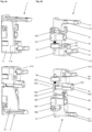
- Fig. 1 shows a functional unit according to the invention or a piece of furniture 1 in the design of a cupboard, in which a door compartment 18 is integrated on both sides.
- the piece of furniture 1 includes side walls 1A, a top shelf 1B, a subfloor 1C and partition walls 1D, each of which delimits a door compartment 18 with an associated side wall 1A.
- a displacement device 10 according to the invention with a mounting profile 14 is arranged in each door compartment 18, which can be moved automatically within the door compartment 18, but without an electric drive motor. Doors 11 are held by the mounting profile 14 and are moved into or out of the associated door compartment 18 when the mounting profile 14 is moved.
- a folding sliding door 11 is held in the first door compartment 18 and has a first and a second door element 111, 112, which are connected to one another in an articulated manner.
- the folding sliding door 11 is completely pulled out of the first door compartment 10 and fully unfolded so that the door elements 111, 112 are aligned in one plane.
- the door elements 111, 112 of the folding sliding door 11 and the door element 111 of the one-piece door 11 are the same size, which is why two thirds of the cabinet opening 100 are covered by the folding sliding door 11 shown in the closed position.
- the edge of the first door element 111 that trails when the folding sliding door 11 is extended is connected by stop hinges 131 to the symbolically shown mounting profile 14, which is held at the exit of the door compartment 18 after the folding sliding door 11 has been extended.
- the leading edge of the first door member 111 is connected by door hinges 132 to the trailing edge of the second door member 112, the leading edge of which is connected at the top to a front drive 5F.
- the front drive 5F is guided in a connecting rail 150, which is connected to the upper guide rails 15 by curved sections, which run into the door compartments 18. When entering the door compartment 18 and when traveling along the connecting rail 150, the front drive 5F runs ahead, with the change of direction taking place within the curve section.
- Fig. 2 shows the one in the first door compartment 18 of the functional unit 1 of Fig. 1 arranged displacement device 10 with a holding device 4 according to Fig. 6 or Fig. 7 (in Fig. 2 shown schematically), from which the mounting profile 14 is held displaceably in a vertical orientation.
- the mounting profile 14, which is held in a vertical orientation by the holding device 4 and which is connected to the folding sliding door 11 by the stop hinges 131, is connected to a drive device 2 and to an auxiliary drive 3.
- the mounting profile 14 can be moved along a travel path S between a first end position S1 on the back of the door compartment 18 and a second end position S2 on the front of the door compartment 18.
- the mounting profile 14 is connected at the upper end to an upper guide drive 5, which is guided in an upper guide rail 15, and at the lower end by a lower guide drive 6, which is guided in a lower guide rail 16.
- the upper guide drive 5 includes support rollers 591 and guide rollers 592 and, in addition to the guide functions, also has a carrying function.
- the lower guide drive 6 includes guide rollers 692 which are guided in the lower guide rail 16.
- the upper guide drive 5 and the lower guide drive 6 lie in Fig. 2 at the second end position S2 on an upper stop device 7 and on a lower stop device 8, which will be described below with reference to Fig. 6 and Fig. 8a and Fig. 8b be explained in more detail.
- a stop device 90 with a stop or a stop plate 9 is provided on the rear first end position S1, which limits the travel path S of the mounting profile 14 on the back of the door compartment 18.
- the displacement device 10 preferably comprises a drive device 2 with a pull cable 22, which is in Fig. 2 not yet installed.
- the mounting profile 14 can preferably be moved over the entire travel path S.
- a drive device 2 with the same function or on the upper guide drive 5 is provided not only at the upper end of the mounting profile 14 or on the upper guide drive 5, but also at the lower end of the mounting profile 14 or on the lower guide drive 6.
- a functionally identical or identical drive device 2 is provided . What is desirable is a high acceleration at the beginning and then a uniform movement of the mounting profile 14.
- an auxiliary drive 3 is provided, by means of which the at least one drive device 2 is in the area of the rear first end position S1 is supported.
- the mounting profile 14 is released from the rear end position S1 or from the stop plate 9, it is additionally accelerated by the auxiliary drive 3 over a relatively short distance.
- a rapid movement sequence is achieved with the auxiliary drive 3.
- the mounting profile 14 does not move sluggishly from the end position S1, but is accelerated quickly.
- damping devices 99 which have a damping piston 991, which is displaced when it hits the stop plate 9 and dampens the movements of the mounting profile 14 and avoids a disruptive impact.
- a cyclically operating locking device 95 which includes an actuating rod 952 and a gripper 951, which can cooperate with a stationarily mounted gripping element 96 and which is activated by pressure on the actuating rod 952, which is activated when the first end position S1 is reached of the gripping element 96 is exercised, can be closed cyclically and released again (see Fig. 11 ). This can thus be locked by manually or motorically exerted pressure on the locking device 95 and unlocked again by further pressure.
- Fig. 2 also shows a retraction device E, by means of which the mounting profile 14 or one of the guide drives 5, 6 can be detected and pulled to the first end position S1.
- the holding device 4 according to the invention can therefore be used without or optionally in combination with one or more drive devices 2, E.
- Fig. 3 shows part of the displacement device 10 from Fig. 2 with the upper end piece of the mounting profile 14, which is connected to an upper guide drive 5, which is slidably mounted in an upper guide rail 15 and which is connected to a drive device 2.
- the drive device 2 comprises a drive unit 21 with a housing 210, in which a drive element 211 is provided and a pulley 212 connected thereto, onto which a pull rope 22 is wound, is rotatably held.
- the drive element 211 is preferably a driving spring, such as a spiral spring or a helical spring, which is tensioned or relaxed as the pulley 212 rotates.
- the pulley 212 is rotatably mounted by means of a bearing shaft 215 (shown schematically).
- the spiral-shaped drive element 211 also encloses the bearing shaft 215 and has a first end piece 2111 with the pulley 212 and a second End piece 2112 is firmly connected to the bearing shaft 215.
- the pulley 212 rotates when the pull rope 22 is pulled out, the first end piece 2111 of the drive element 211 is therefore guided around the bearing shaft 215, while the second end piece 2112 of the drive element 211 is held in place.
- the pulley 212 is turned back again by the tensioned drive element 211.
- the coupling element 221 is suspended at the end of the pull rope 22, for example on the front of a pull rope connection, and the mounting profile 14 is inserted into the door compartment 18, the pull rope 22 is pulled out of the drive unit 21, the pulley 212 is rotated and the drive element 211 is tensioned.
- the mounting profile 14 can now be locked with the locking device 95 when the second end position S2 is reached.
- the pulley 212 is turned back by the drive element 211 and the pull rope 22 is retracted and the mounting profile 14 is moved from the first end position S1 to the second end position S2.
- a door 11 connected to the mounting profile 14 is therefore automatically extended from the door compartment 18.
- the displacement device 10 can be installed in differently sized door compartments 18 without modification . As described below, adjustments and adjustments can be made with minimal effort. Even if the displacement device 10 is provided with a drive device 2 on the top of the mounting profile 14 and a drive device 2 on the underside of the mounting profile 14, the assembly of the displacement device 10 can be carried out with minimal effort.
- Fig. 3 also shows that the mounting profile 14 has two guide channels 141, 142 and a mounting channel 143, in which the stop hinges 131 are held in a form-fitting manner and can be fixed by locking screws 1311.
- At least one of the guide channels 141, 142 serves to hold a deflection unit 230, which can be moved along the mounting profile 14 and fixed at a suitable location using locking screws.
- the upper guide drive 5 comprises a two-part drive body 51 with a first drive body part 511 and a second drive body part 512, of which vertically aligned support rollers 591 and horizontally aligned guide rollers 592 are held.
- the two drive body parts 511, 512 can be connected to one another in one piece, but in this embodiment they are connected to one another by a coupling part 55.
- the support rollers 591 are supported on a running element 151 of the upper guide rail 15 and the guide rollers 592 are guided in a guide channel 152 of the upper guide rail 15.
- a buffer or damper 58 is inserted into the drive body 51.
- the upper guide drive 5 includes a stop part 53, which can cooperate with a buffer or damper on the front stop device 7.
- Fig. 4 shows the upper guide drive 5 of Fig. 3 from the other side and detached from the mounting profile 14, on which a deflection unit 230 with a first deflection roller 23 is held in a displaceable and fixable manner.
- the deflection unit 230 is held in a form-fitting manner in a guide channel 141 or 142 and can be moved along this and locked at a suitable location.
- the pull rope 22 of the drive device 2 is guided around the first deflection roller 23 to a second deflection roller 24, which is held by the drive body 51 of the upper guide drive. From the second deflection roller 24, the pull rope 22 is guided further to a pull rope connection 72, which is arranged on the upper stop device 7 (see Fig. 5 ).
- the path from the pull rope pulley 212 to the second deflection pulley 24 can be lengthened or shortened.
- a corresponding length of the pull cable 22 is pulled out of the drive unit 21, the pull cable pulley 212 is rotated accordingly and the drive element 211 is pretensioned accordingly.
- Pretensioning the drive element 211 therefore causes it to act on the traction cable 22 with a higher tensile force and the mounting profile 14 to be moved with a higher force from the first end position S1 towards the second end position S2. This setting can be easily made in just a few steps.
- Fig. 4 further shows that the first drive body part 511 has a downwardly directed mounting sword 5111, which can be inserted into a mounting opening 140 of the mounting profile 14. A part of the mounting profile 14 is held between the mounting sword 5111 and a holding plate 5112.
- the first drive body part 511 also holds a bearing shaft 415, from which a first upper roller unit 411 and a second upper roller unit 412 are rotatably supported.
- the first and second roller units 411, 412 the form a pair of rollers 41, are part of the holding device 4, which is explained below.
- a functional part 57 rests above the pair of rollers 41, which in Fig. 6 tethers 421, 422 shown.
- a damper channel 5120 is provided in the second drive body part 512, in which a drive damper 58 is arranged and fixed by means of a locking element, possibly a fixing screw 5121.
- Fig. 5 shows the upper part of the displacement device 10 from Fig. 2 with the drive device 2, from which the pull cable 22 is guided via the first deflection roller 23 of the deflection unit 230 which is slidably connected to the mounting profile 14 and the second deflection roller 24 connected to the upper guide carriage 5 to a pull cable connection 72 on the upper stop device 7, which is on the Front side of the upper guide rail 15 is held.
- the coupling part 221 is grasped at the end of the pull rope 2, guided around the first and second deflection rollers 23, 24 and hooked into the pull rope connection 72 of the upper stop device 7. This process can be carried out in just a few steps.
- the stop device 7 is equipped with a mounting beam 711 (see Fig. 8b ) held in a holding channel 157, which is provided on the underside of the running element 151 of the upper guide rail 15.
- a mounting beam 711 (see Fig. 8b ) held in a holding channel 157, which is provided on the underside of the running element 151 of the upper guide rail 15.
- Above the running element 151 is therefore the running technology with the support rollers 591 and the guide rollers 592 of the upper guide drive 5 (see Fig. 3 ) and an adjusting part 159 for adjusting the damper engagement depth, which can interact with the drive damper 58.
- the drive technology with the pull rope 22 and the holding technology of the holding device 4 with holding ropes 421, 422 are provided (see also Fig. 6 ).
- the stop device 7 includes a spacer roller 79 on one or both sides, on which the held door 11, which is shown in a sectional view, can roll without closing the body 71 of the stop device 7 touch.
- the upper stop device 7 includes a cable connection device 74, by means of which one of the retaining cables 421 of the retaining device 4 is held.
- a stop damper or stop buffer 78 is provided, which can interact with the stop part 53 of the upper guide drive 5 (see Fig. 4 ).
- Fig. 6 shows the displacement device 10 from Fig. 2 with a holding device 4 according to the invention, which comprises two holding ropes 421, 422.
- the upper guide drive 5 provided at the upper end of the mounting profile 14 is guided in the upper guide rail 15 and the lower guide drive 6 provided at the lower end of the mounting profile 14 is guided on a lower guide rail 16.
- the upper stop device 7 is shown on the front of the upper guide rail 15 and the lower stop device 8 is shown on the front of the lower guide rail 16 (see also Fig. 7 ).
- the guide rails 15, 16 are not shown.
- the upper front stop device 7 with the mounting beam 711, the pull rope connection 72 and the rope connection device 74 for the second tether 422 has already been described with reference to Fig. 5 explained.
- the rotary lever 75 serves to hold the mounting profile 14 in the front end position S2. In this position, the mounting profile 14 is held vertically aligned, so that the door 11 or the door elements 111, 112 can be mounted particularly easily.
- the upper cable connection device 74 includes a mounting channel 741 (see Fig. 8b ) with a subsequent recess into which an end piece of the upper retaining cable 422 can be inserted.
- the lower stop device 8 and the upper stop device 7 are referred to below Fig. 8a and Fig. 8b described.
- the second pull rope 422 is held in place by the pull rope connection 74 of the upper stop device 7.
- the pull cable connection 84 of the lower stop device 8 comprises an adjusting slide 842, which is slidably mounted and adjustable by means of an adjusting screw 845.
- An adjusting device 840 is formed by the adjusting screw 845 and the adjusting slide 842.
- the holding device 4 comprises a first front cable connection device 84, a first lower roller unit 431, which is arranged at the lower end of the mounting profile 14, a first upper roller unit 411, which is arranged at the upper end of the mounting profile 14, and a first rear cable connection device 44, which is arranged at the rear end of the upper guide rail 15, as well as the first tether 421, which is connected with a first end piece to the first front cable connection device 84, guided counterclockwise around the first lower roller unit 431 and clockwise around the first upper roller unit 411 and with a second end piece is connected to the first rear cable connection device 44.
- the holding device 4 comprises a second front cable connection device 74, a second upper roller unit 412, which is arranged at the upper end of the mounting profile 14, a second lower roller unit 432, which is arranged at the lower end of the mounting profile 14, and a second rear cable connection device 45, which is arranged at the rear end of the lower guide rail 16, as well as the second tether 422, which is connected with a first end piece to the second front cable connection device 74, guided clockwise around the second upper roller unit 412 and counterclockwise around the second lower roller unit 432 and with a second end piece is connected to the second rear cable connection device 45.
- the first front cable connection device 84 is provided at the front end of the lower guide rail 16 on the lower stop device 8.
- the second front cable connection device 74 is arranged at the front end of the upper guide rail 15 on the upper stop device 7.
- the second rear cable connection device 45 comprises a second tensioning device 450 with a second tension spring 453, which is connected, on the one hand, directly or via a second connection carriage 452 (shown in dash-dotted lines) to the second tether 422 and, on the other hand, to a second tension carriage 454, in which a stationary one is connected second tensioning screw 455 is screwed in, by means of which the second tension carriage 454 can be displaced within a second bearing profile 459 along its longitudinal axis in order to tension the second tension spring 453.
- the tension spring 453 is tensioned and a corresponding tensile force is transferred to the second retaining cable 422.
- one of the holding ropes in this embodiment the second holding rope 422, is therefore always held elastically.
- the first tether 421 is held inelastically or firmly by the first front cable connection device 84 and the first rear cable connection device 44.
- the vertical alignment of the mounting profile 14 can be carried out using the first adjusting device 840.
- the second tension spring 453 is prestressed or stretched by a predetermined amount. If the second tension spring 453 is connected on the one hand to the tension carriage 454 and on the other hand to the connection carriage 452 is, the amount of mutual displacement of the pulling carriage 454 and the connecting carriage 452 corresponds to the tensile force in the tension spring 453. The impressed tensile force can therefore be easily determined based on this displacement. When using a connection carriage 452, the tether 422 can be connected more easily, as described below.
- a tensile force is preferably also impressed into the first tether 421 before it is fixed.
- a tensile force is preferably also impressed into the first tether 421 before it is fixed.
- the preferably provided drive device 2 which is held by the upper guide carriage 5, was described with reference to Fig. 3 already described.
- the pull cable 22 of the drive device 2 is guided via the first deflection roller 23 and the second deflection roller 24 to the pull cable connection 72, which is provided on the upper front stop device 7.
- the deflection unit 230 is held in a form-fitting manner with a shaped element 232 in the first guide channel 141 and can be moved along the mounting profile 14.
- Fig. 7 shows the displacement device 10 from Fig. 6 with the two rear cable connection devices 44, 45 of the holding device 4, each of which has a bearing profile 449, 459 which is connected to the rear end piece of the upper or lower guide rail 15, 16.
- the bearing profiles 449, 459 have an elongated bearing opening 4490, 4590 through which the device parts are only partially visible.
- the device parts provided in the bearing profiles 449, 459, each of which includes a tension spring 443, 453, were therefore duplicated and shown separately.
- the tension springs 443, 453 are also shown separately.
- Each of the cable connection devices 44, 45 comprises an input roller 441, 451, a connection carriage 442, 452, a tension spring 443, 453, a tension carriage 444, 454, a tension screw 445, 455 and a screw holder 446, 456 anchored in the bearing profile 449, 459, by means of which holds the clamping screw 445, 455.
- the screw holders 446, 456 are each secured by means of a month screw 4461 with the associated bearing profile 449; 459 connected.
- the facing end piece of the associated tether 421, 422 is guided via the input roller 441, 451 to the connecting carriage 442, 452, which is connected by the tension spring 443, 453 to the tension carriage 444, 454, which in turn is connected to the screw holder by the tension screw 445, 455 446, 456 is connected.
- the tension spring 443, 453 is tensioned.
- the tensile force exerted by the tension spring 443, 453 is transmitted to the connected tether 421, 422 via the connecting carriage 442, 452.
- the parts of the cable connection devices 44, 45 mentioned therefore form tensioning devices 440, 450, by means of which a tensile force in the retaining cables 421, 422 can be adjusted.
- connection carriage 452 in the second cable connection device 45 is only provided as an option.
- the connection carriage 442 is always present so that the first traction cable 421 can be fixed after the tensile force has been impressed.
- a fixing screw 448 is provided in the connecting carriage 442 of the first rear cable connection device 44, which is passed through the profile opening 4490 in the bearing profile 449 and is clamped to the bearing profile 449 when tightened. Parts of the bearing profile 449 are therefore shown symbolically below the fixing screw 448.
- a predetermined tensile stress is impressed in the second tether 422 and the mounting profile 14 is vertically aligned by means of the tensioned first tether 421.
- This installation process is optimized by impressing a predetermined tensile force in the first retaining cable 421 before the adjustment or vertical alignment of the mounting profile 14. After impressing a predetermined tensile force in both retaining cables 421, 422, the effort required to adjust or vertically align the mounting profile 14 is reduced.
- the first tether 421 is additionally connected in the first rear cable connection device 44 to the first connection carriage 442, after which the first tension screw 445 is rotated and the first tension carriage 444 and the first connection carriage 442 are connected to one another by the first tension spring 443 are to be shifted relative to one another by a predetermined amount.
- the predetermined tensile forces are impressed in both pull ropes 421, 422. These adjustments are preferably made taking into account the measuring rods, which determine the extent of the mutual displacement of the Display the connection carriage 442, 452 and the pull carriage 444, 454 preferably on a scale with markings, if necessary color markings.
- the first connecting carriage 442 is fixed to the associated first bearing profile 449 after the predetermined tensile stress has been impressed.
- the first front adjusting device 840 is then actuated, as described, in order to vertically align the no longer fixed mounting profile 14. Usually only minimal corrections are necessary.
- a second drive device 2' and a second displaceably mounted deflection unit with a first deflection roller 23' can also be provided on the underside of the mounting profile 14.
- the lower pull rope would in turn be guided via the first deflection roller 23 'and a deflection roller which is attached, for example, to the lower guide drive 6 to a pull cable connection 82 on the lower stop device 8.
- Fig. 8a shows the upper stop device 7 and the lower stop device 8 from Fig. 7 in spatial representation.
- Fig. 8b shows the upper stop device 7 and the lower stop device 8 from Fig. 7 in sectional view.
- the upper stop device 7 and the lower stop device 8 each have a device body 71, 81 and a mounting beam 711, 811 formed thereon, which can be locked in the associated upper or lower guide rail 15, 16 by means of locking screws 712, 812.
- the upper stop device 7 has a hook-shaped pull rope connection 72, in which the coupling part 221 of the pull rope 22 can be suspended.
- each stop device 7, 8 preferably has a spacer roller 79, 89 on both sides, which keeps the passing door 11 at a distance, and a rotatable locking lever 75, 85, by means of which the mounting profile 14 can be fixed at the front in order to carry out installation work, maintenance work or adjustments .
- the locking lever 85 could also be used as a pull cable connection 82.
- the locking levers 75, 85 are held by a holding shell 710, 810, which is connected to the device body 71, 81 by a screw.
- each stop device 7, 8 has a preferably adjustable stop buffer 78, 88 with a buffer body 781, 881 and an adjusting screw 782, 882.
- the cable connection device 74 of the upper stop device 7 is designed simply and has a holding block 742 with an upwardly open mounting channel 741 into which an end piece of the second holding cable 422 can be hung.
- the lower stop device 8 includes a cable connection device 84 with an adjusting device 840, which is formed by a displaceable adjusting slide 842 and an adjusting screw 845, by means of which the adjusting slide 842 can be displaced within a bearing profile 843.
- the adjusting carriage 842 has a mounting channel 841 into which the end piece of the first retaining cable 421 can be hung.
- the lower stop device 8 has a plunger 86, which is axially displaceable by means of an adjusting screw 861 and which can interact with the integrated drive damper 68 of the lower guide drive 6.
- Fig. 9a shows the upper rear cable connection device 44 and Fig. 9b shows the lower rear cable connection device 45, which is related to Fig. 7 have already been briefly described.
- the input roller 441 of the upper rear cable connection device 44 is held by a roller holder 4411, which can be clamped within the bearing profile 449 by means of a tensioning element 4412.
- the input roller 451 of the lower rear cable connection device 45 is held by a roller holder 4511, which can be clamped within the bearing profile 459 by means of a tensioning element 4512.
- the optional connecting carriages 442, 452 have clamping jaws 4421, 4422 or 4521, 4522, which can be pressed against each other by clamping screws 4423, 4523 in order to fix the end piece of the relevant tether 421, 422 inserted between them.
- the retaining ropes 421, 422 can therefore be pulled through the connecting carriages 442, 452, tensioned and fixed manually.
- the fixing screw 448 by means of which the first connecting carriage 442 can be fixed to the associated first bearing profile 449. After fixing the first connection carriage 442, the first Tension spring 443 no longer has a relevant effect. The elasticity of the holding device 4 subsequently determines the tension spring 453 of the second cable connection device 45, which is still active.
- the mentioned parts of the cable connection devices 44, 45 form tensioning devices 440, 450, by means of which a tensile force in the retaining cables 421, 422 can be adjusted.
- a measuring rod 447, 457 with a control window 4570 is provided to set a desired tensile force.
- the measuring rod 457 is connected to the connecting carriage 452 and overlaps a scale 4471, 4571 which is provided on the pulling carriage 444, 454.
- the mutual displacement of the connecting carriage 442, 452 and the pulling carriage 444, 454, which are slidably mounted in the bearing profile 449, 459, can therefore be read using the measuring rod 447, 457.
- Fig. 10 shows the auxiliary drive 3 of Fig. 2 , which is held by the mounting profile 14 and which interacts with a rear end stop 9 after the sliding door 11 has been pushed into the door compartment 18.
- the auxiliary drive 3 comprises a housing 33 and at least one extendable piston 32, which is supported by a spring element 31 and which rests on the end stop 9 after the mounting profile 14 has entered the door compartment 18.
- the spring element 31 of the auxiliary drive 3 is tensioned as soon as the mounting profile 14 moves towards the first end position S1 within the door compartment 18. After reaching the end position, the spring element 31 of the auxiliary drive 3 is loaded and can support the drive device 2 at the beginning of the exit of the mounting profile 14 towards the second end position S2.
- the mounting profile 14 is also connected to a cyclically operating locking device 95, which includes an actuating rod 952 and a gripper 951, which cooperate with a stationary mounted gripping element 96 and can be closed and released cyclically by pressing on the actuating rod 952.
- the gripper 951 is closed by a first displacement of the actuating rod 952, which is arranged in a device housing 953 and supported by a spring, and the gripper 951 is opened again by a second displacement of the actuating rod 952.
- the actuating rod 952 is preferably arranged coaxially to the central axis of the gripper 951, so that the actuating rod 952 can be actuated by the gripping element 96, which is gripped by the gripper 951 and released again.
- the gripping element 96 is arranged on the stop plate 9 of the stop device 90, which is attached to the intermediate wall 1D functional unit 1.
- the displacement path of the actuating rod 952 is shown by a dash-dotted line. Shortly before reaching At the end position S1 it hits the gripping element 96 and is pushed back by it, whereby the gripping device 95 is actuated and coupled to the gripping element 96.
- damping devices 99 with damping pistons 991 are provided, which hit the stop plate 9 as soon as the mounting profile 14 reaches the end position S1.
- auxiliary drive 3, the gripping device 95 and the damping devices 99 are optionally provided and can be replaced by functionally identical devices.
- Fig. 11 shows a mounting configuration of the displacement device 10, which has a mounting profile set 14 ', which releasably holds the upper guide drive 5 and the lower guide drive 6, an upper guide rail set 15', which releasably holds the upper stop device 7 and the first rear cable connection device 44 and with the upper guide drive 5 is connected, a lower guide rail replacement 16 ', which releasably holds the lower stop device 8 and the second rear cable connection device 45 and is connected to the lower guide carriage 6, as well as the pre-assembled tethers 421, 422.
- the retaining ropes 421, 422 are connected at the front to the rope connection devices 74, 84 of the stop devices 8, 7 and at the rear to the rope connection devices 44, 45.
- Fig. 11 also shows one of the partition walls 1D of Fig. 1 , on which the lower and upper guide rails 15, 16 are already mounted and to which the displacement device 10 present in the mounting configuration is transferred. Installation is particularly easy if the partition 1D is aligned horizontally.
- the assembly configuration of the displacement device 10 can therefore advantageously be created by the manufacturer during the installation of the Displacement device 10 at the installation site can be carried out by the user in a simple manner with almost no instructions, for example with the installation steps described below.
- the mounting profile set 14' is replaced by the mounting profile 14 in a first installation step.
- the guide drives 5, 6, which are now connected to the mounting profile 14, are inserted into the associated upper or lower guide rails 15, 16, which are connected to the intermediate wall 1D.
- the stop devices 7, 8 are detached from the upper and lower guide rail replacements 15', 16' and inserted into the upper and lower guide rails 5, 6.
- the mounting beam 711 of the upper stop device 7 is inserted into the mounting channel 153 of the upper guide rail 5 and the mounting beam 811 of the lower stop device 8 is inserted into the mounting channel 163 of the lower guide rail.
- the rear cable connection devices 44, 45 are detached from the upper and lower guide rail replacements 15', 16' and connected to the upper and lower guide rails 5, 6.
- a mounting strip 4495 of the first rear cable connection device 44 is screwed to a mounting connection 154 of the upper guide rail 15.
- the second rear cable connection device 45 is inserted into the mounting channel 163 of the lower guide rail 16 with a mounting beam 45111, which is connected to the associated roller holder 4511.
- the upper guide rail replacement 15' is detached from the upper guide track 5 and the lower guide rail replacement 16' is detached from the lower guide drive 6.
- the displacement device 10 is connected solely to the upper and lower guide rails 15, 16.
Landscapes
- Engineering & Computer Science (AREA)
- Mechanical Engineering (AREA)
- Power-Operated Mechanisms For Wings (AREA)
- Closing And Opening Devices For Wings, And Checks For Wings (AREA)
Priority Applications (3)
| Application Number | Priority Date | Filing Date | Title |
|---|---|---|---|
| EP22176723.9A EP4286631A1 (fr) | 2022-06-01 | 2022-06-01 | Dispositif coulissant doté d'un profilé de montage, procédé d'installation et unité fonctionnelle |
| PCT/EP2023/062855 WO2023232441A1 (fr) | 2022-06-01 | 2023-05-12 | Dispositif coulissant doté d'un profilé de montage, procédé d'installation et unité fonctionnelle |
| TW112118128A TW202413784A (zh) | 2022-06-01 | 2023-05-16 | 具有安裝型材的位移裝置、安裝方法和功能實體 |
Applications Claiming Priority (1)
| Application Number | Priority Date | Filing Date | Title |
|---|---|---|---|
| EP22176723.9A EP4286631A1 (fr) | 2022-06-01 | 2022-06-01 | Dispositif coulissant doté d'un profilé de montage, procédé d'installation et unité fonctionnelle |
Publications (1)
| Publication Number | Publication Date |
|---|---|
| EP4286631A1 true EP4286631A1 (fr) | 2023-12-06 |
Family
ID=81878113
Family Applications (1)
| Application Number | Title | Priority Date | Filing Date |
|---|---|---|---|
| EP22176723.9A Pending EP4286631A1 (fr) | 2022-06-01 | 2022-06-01 | Dispositif coulissant doté d'un profilé de montage, procédé d'installation et unité fonctionnelle |
Country Status (3)
| Country | Link |
|---|---|
| EP (1) | EP4286631A1 (fr) |
| TW (1) | TW202413784A (fr) |
| WO (1) | WO2023232441A1 (fr) |
Citations (6)
| Publication number | Priority date | Publication date | Assignee | Title |
|---|---|---|---|---|
| DE2045763A1 (de) | 1970-08-13 | 1972-06-15 | Hawa Ag, Mettmenstetten (Schweiz) | Türe |
| US5078461A (en) * | 1989-04-25 | 1992-01-07 | Herman Miller, Inc. | Cabinet with pocketing doors |
| EP1394349A1 (fr) | 2002-08-27 | 2004-03-03 | Hawa Ag | Dispositif de translation pour éléments de séparation montées pivotantes et meuble ainsi équipé |
| US8336972B2 (en) | 2009-04-28 | 2012-12-25 | Hawa Ag | Displacement device for pivotally held separation elements and article of furniture |
| US9284761B2 (en) | 2012-12-05 | 2016-03-15 | Hawa Ag | Displacement device for slidable and turnable separation elements and functional entity |
| US10227806B2 (en) | 2014-11-26 | 2019-03-12 | Julius Blum Gmbh | Arrangement of a door and cavity for an article of furniture |
Family Cites Families (1)
| Publication number | Priority date | Publication date | Assignee | Title |
|---|---|---|---|---|
| US4976502A (en) | 1989-04-25 | 1990-12-11 | Herman Miller, Inc. | Cabinet with pocketing doors |
-
2022
- 2022-06-01 EP EP22176723.9A patent/EP4286631A1/fr active Pending
-
2023
- 2023-05-12 WO PCT/EP2023/062855 patent/WO2023232441A1/fr unknown
- 2023-05-16 TW TW112118128A patent/TW202413784A/zh unknown
Patent Citations (6)
| Publication number | Priority date | Publication date | Assignee | Title |
|---|---|---|---|---|
| DE2045763A1 (de) | 1970-08-13 | 1972-06-15 | Hawa Ag, Mettmenstetten (Schweiz) | Türe |
| US5078461A (en) * | 1989-04-25 | 1992-01-07 | Herman Miller, Inc. | Cabinet with pocketing doors |
| EP1394349A1 (fr) | 2002-08-27 | 2004-03-03 | Hawa Ag | Dispositif de translation pour éléments de séparation montées pivotantes et meuble ainsi équipé |
| US8336972B2 (en) | 2009-04-28 | 2012-12-25 | Hawa Ag | Displacement device for pivotally held separation elements and article of furniture |
| US9284761B2 (en) | 2012-12-05 | 2016-03-15 | Hawa Ag | Displacement device for slidable and turnable separation elements and functional entity |
| US10227806B2 (en) | 2014-11-26 | 2019-03-12 | Julius Blum Gmbh | Arrangement of a door and cavity for an article of furniture |
Also Published As
| Publication number | Publication date |
|---|---|
| WO2023232441A1 (fr) | 2023-12-07 |
| TW202413784A (zh) | 2024-04-01 |
Similar Documents
| Publication | Publication Date | Title |
|---|---|---|
| WO2009076785A1 (fr) | Dispositif de traction et d'amortissement d'une porte coulissante logée dans un rail profilé pour le guidage de mécanismes de roulement, vers la position terminale | |
| EP3997293B1 (fr) | Dispositif pour guider une porte coulissante ou une porte accordéon sur une paroi de meuble | |
| EP1314842A1 (fr) | Dispositif d'ouverture et de fermeture pour une partie de meuble mobile | |
| EP3199078B1 (fr) | Séparation de douche comprenant une porte coulissante pouvant se déplacer dans des positions finales au moyen d'une unité d'amortisseurs à ressort | |
| EP2992156B1 (fr) | Système de guidage d'une porte coulissante, porte coulissante et meuble | |
| EP4004316B1 (fr) | Ensemble raccord pour un ouvrant qui peut être éloigné en parallèle et ensemble fermeture pour une ouverture de bâtiment | |
| EP3399127A1 (fr) | Ferrure de meuble pour un mouvement coulissant d'une porte en plusieurs parties et meuble doté d'une telle ferrure de meuble | |
| EP4286631A1 (fr) | Dispositif coulissant doté d'un profilé de montage, procédé d'installation et unité fonctionnelle | |
| DE112006000292B4 (de) | Dämpfungs- und Auszugsvorrichtung für zwei Möbelteile | |
| EP3833837B1 (fr) | Dispositif pour fermer la porte coulissante d'un arrangement de porte coulissante | |
| EP4286633A1 (fr) | Dispositif coulissant doté d'un profilé de montage et unité fonctionnelle | |
| EP4083363A1 (fr) | Dispositif coulissant pour porte coulissante, agencement et dispositif d'entraînement | |
| AT522708B1 (de) | Anordnung zur Führung einer Schiebetür oder Falt-Schiebetür an einer Möbelwand | |
| DE102022203507A1 (de) | Haushaltsgerät mit versenkbarer Tür und dazu spezifisch ausgebildeter Seilzugvorrichtung | |
| EP2045425B1 (fr) | Porte basculante à un panneau et dispositif de précontrainte correspondant | |
| DE202021004263U1 (de) | Verschiebevorrichtung für eine Schiebetür, Anordnung und Antriebsvorrichtung | |
| EP4083361A1 (fr) | Dispositif pliant pour une porte pliante et mobilier pourvu de porte pliante | |
| EP2527575B1 (fr) | Ferrure de porte coulissante | |
| DE102010030136A1 (de) | Möbelstück mit Auszug | |
| WO2023232440A1 (fr) | Dispositif de coulissement comprenant un élément de montage profilé, et unité fonctionnelle | |
| DE19859706C2 (de) | Zwei-Schienen-Fensterheber zum Anheben und Absenken einer Scheibe | |
| WO2023232979A1 (fr) | Unité fonctionnelle dotée d'un compartiment de porte pour une porte pouvant être maintenue avec faculté de déplacement | |
| AT526951B1 (de) | Verfahren zur Montage eines Führungssystems zur Führung wenigstens eines bewegbar gelagerten Türflügels entlang einer Möbelwand | |
| DE102010052374B4 (de) | Torantrieb mit Linearführung | |
| AT502660B1 (de) | Einzugsvorrichtung |
Legal Events
| Date | Code | Title | Description |
|---|---|---|---|
| PUAI | Public reference made under article 153(3) epc to a published international application that has entered the european phase |
Free format text: ORIGINAL CODE: 0009012 |
|
| STAA | Information on the status of an ep patent application or granted ep patent |
Free format text: STATUS: THE APPLICATION HAS BEEN PUBLISHED |
|
| AK | Designated contracting states |
Kind code of ref document: A1 Designated state(s): AL AT BE BG CH CY CZ DE DK EE ES FI FR GB GR HR HU IE IS IT LI LT LU LV MC MK MT NL NO PL PT RO RS SE SI SK SM TR |