EP4286631A1 - Displacement device with a mounting profile, installation method and functional unit - Google Patents
Displacement device with a mounting profile, installation method and functional unit Download PDFInfo
- Publication number
- EP4286631A1 EP4286631A1 EP22176723.9A EP22176723A EP4286631A1 EP 4286631 A1 EP4286631 A1 EP 4286631A1 EP 22176723 A EP22176723 A EP 22176723A EP 4286631 A1 EP4286631 A1 EP 4286631A1
- Authority
- EP
- European Patent Office
- Prior art keywords
- carriage
- cable connection
- profile
- mounting profile
- drive
- Prior art date
- Legal status (The legal status is an assumption and is not a legal conclusion. Google has not performed a legal analysis and makes no representation as to the accuracy of the status listed.)
- Pending
Links
- 238000006073 displacement reaction Methods 0.000 title claims abstract description 124
- 238000009434 installation Methods 0.000 title claims abstract description 27
- 238000000034 method Methods 0.000 title claims description 9
- 238000013016 damping Methods 0.000 description 9
- 230000008878 coupling Effects 0.000 description 7
- 238000010168 coupling process Methods 0.000 description 7
- 238000005859 coupling reaction Methods 0.000 description 7
- 238000005192 partition Methods 0.000 description 7
- 238000012423 maintenance Methods 0.000 description 4
- 125000006850 spacer group Chemical group 0.000 description 4
- 230000005540 biological transmission Effects 0.000 description 3
- 238000013461 design Methods 0.000 description 3
- 238000005516 engineering process Methods 0.000 description 3
- 239000002184 metal Substances 0.000 description 3
- 238000003825 pressing Methods 0.000 description 3
- 238000011900 installation process Methods 0.000 description 2
- 229910000831 Steel Inorganic materials 0.000 description 1
- 230000001133 acceleration Effects 0.000 description 1
- 230000008859 change Effects 0.000 description 1
- 239000003086 colorant Substances 0.000 description 1
- 238000004040 coloring Methods 0.000 description 1
- 230000000295 complement effect Effects 0.000 description 1
- 238000012937 correction Methods 0.000 description 1
- 230000000694 effects Effects 0.000 description 1
- 230000004048 modification Effects 0.000 description 1
- 238000012986 modification Methods 0.000 description 1
- 239000010970 precious metal Substances 0.000 description 1
- 230000036316 preload Effects 0.000 description 1
- 230000008569 process Effects 0.000 description 1
- 238000005096 rolling process Methods 0.000 description 1
- 238000004904 shortening Methods 0.000 description 1
- 239000010959 steel Substances 0.000 description 1
- 238000012360 testing method Methods 0.000 description 1
Images


Classifications
-
- E—FIXED CONSTRUCTIONS
- E05—LOCKS; KEYS; WINDOW OR DOOR FITTINGS; SAFES
- E05D—HINGES OR SUSPENSION DEVICES FOR DOORS, WINDOWS OR WINGS
- E05D15/00—Suspension arrangements for wings
- E05D15/26—Suspension arrangements for wings for folding wings
-
- E—FIXED CONSTRUCTIONS
- E05—LOCKS; KEYS; WINDOW OR DOOR FITTINGS; SAFES
- E05D—HINGES OR SUSPENSION DEVICES FOR DOORS, WINDOWS OR WINGS
- E05D15/00—Suspension arrangements for wings
- E05D15/26—Suspension arrangements for wings for folding wings
- E05D15/264—Suspension arrangements for wings for folding wings for bi-fold wings
-
- E—FIXED CONSTRUCTIONS
- E05—LOCKS; KEYS; WINDOW OR DOOR FITTINGS; SAFES
- E05D—HINGES OR SUSPENSION DEVICES FOR DOORS, WINDOWS OR WINGS
- E05D15/00—Suspension arrangements for wings
- E05D15/56—Suspension arrangements for wings with successive different movements
- E05D15/58—Suspension arrangements for wings with successive different movements with both swinging and sliding movements
-
- E—FIXED CONSTRUCTIONS
- E05—LOCKS; KEYS; WINDOW OR DOOR FITTINGS; SAFES
- E05Y—INDEXING SCHEME RELATING TO HINGES OR OTHER SUSPENSION DEVICES FOR DOORS, WINDOWS OR WINGS AND DEVICES FOR MOVING WINGS INTO OPEN OR CLOSED POSITION, CHECKS FOR WINGS AND WING FITTINGS NOT OTHERWISE PROVIDED FOR, CONCERNED WITH THE FUNCTIONING OF THE WING
- E05Y2201/00—Constructional elements; Accessories therefore
- E05Y2201/40—Motors; Magnets; Springs; Weights; Accessories therefore
- E05Y2201/47—Springs; Spring tensioners
- E05Y2201/488—Traction springs
-
- E—FIXED CONSTRUCTIONS
- E05—LOCKS; KEYS; WINDOW OR DOOR FITTINGS; SAFES
- E05Y—INDEXING SCHEME RELATING TO HINGES OR OTHER SUSPENSION DEVICES FOR DOORS, WINDOWS OR WINGS AND DEVICES FOR MOVING WINGS INTO OPEN OR CLOSED POSITION, CHECKS FOR WINGS AND WING FITTINGS NOT OTHERWISE PROVIDED FOR, CONCERNED WITH THE FUNCTIONING OF THE WING
- E05Y2201/00—Constructional elements; Accessories therefore
- E05Y2201/60—Suspension or transmission members; Accessories therefore
- E05Y2201/606—Accessories therefore
- E05Y2201/62—Synchronisation of transmission members
-
- E—FIXED CONSTRUCTIONS
- E05—LOCKS; KEYS; WINDOW OR DOOR FITTINGS; SAFES
- E05Y—INDEXING SCHEME RELATING TO HINGES OR OTHER SUSPENSION DEVICES FOR DOORS, WINDOWS OR WINGS AND DEVICES FOR MOVING WINGS INTO OPEN OR CLOSED POSITION, CHECKS FOR WINGS AND WING FITTINGS NOT OTHERWISE PROVIDED FOR, CONCERNED WITH THE FUNCTIONING OF THE WING
- E05Y2201/00—Constructional elements; Accessories therefore
- E05Y2201/60—Suspension or transmission members; Accessories therefore
- E05Y2201/622—Suspension or transmission members elements
- E05Y2201/644—Flexible elongated pulling elements; Members cooperating with flexible elongated pulling elements
- E05Y2201/654—Cables
-
- E—FIXED CONSTRUCTIONS
- E05—LOCKS; KEYS; WINDOW OR DOOR FITTINGS; SAFES
- E05Y—INDEXING SCHEME RELATING TO HINGES OR OTHER SUSPENSION DEVICES FOR DOORS, WINDOWS OR WINGS AND DEVICES FOR MOVING WINGS INTO OPEN OR CLOSED POSITION, CHECKS FOR WINGS AND WING FITTINGS NOT OTHERWISE PROVIDED FOR, CONCERNED WITH THE FUNCTIONING OF THE WING
- E05Y2201/00—Constructional elements; Accessories therefore
- E05Y2201/60—Suspension or transmission members; Accessories therefore
- E05Y2201/622—Suspension or transmission members elements
- E05Y2201/644—Flexible elongated pulling elements; Members cooperating with flexible elongated pulling elements
- E05Y2201/658—Members cooperating with flexible elongated pulling elements
- E05Y2201/672—Tensioners, tension sensors
-
- E—FIXED CONSTRUCTIONS
- E05—LOCKS; KEYS; WINDOW OR DOOR FITTINGS; SAFES
- E05Y—INDEXING SCHEME RELATING TO HINGES OR OTHER SUSPENSION DEVICES FOR DOORS, WINDOWS OR WINGS AND DEVICES FOR MOVING WINGS INTO OPEN OR CLOSED POSITION, CHECKS FOR WINGS AND WING FITTINGS NOT OTHERWISE PROVIDED FOR, CONCERNED WITH THE FUNCTIONING OF THE WING
- E05Y2900/00—Application of doors, windows, wings or fittings thereof
- E05Y2900/20—Application of doors, windows, wings or fittings thereof for furnitures, e.g. cabinets
- E05Y2900/212—Doors disappearing in pockets in the furniture body
Definitions
- the invention relates to a displacement device with a mounting profile, which is connected to a one-piece or multi-part door, possibly a folding sliding door, vertically aligned and preferably automatically displaceable within a door compartment, a functional unit, in particular a piece of furniture or a room unit, with at least one displacement device, and a method for installing the displacement device within the functional unit.
- one-piece or multi-part doors are often used, which are moved into a door compartment of the functional unit after the opening has been released in order not to appear disruptive.
- the US8336972B2 discloses a piece of furniture with a displacement device, by means of which a mounting profile connected to a one-piece door can be displaced within a door compartment.
- the displacement device comprises a holding device in the form of a scissor cross, by means of which the mounting profile is held displaceably in a vertical orientation.
- the displacement device also includes running rails along which the mounting profile is slidably mounted by means of drives.
- the US9284761B2 discloses a piece of furniture with a displacement device, by means of which a mounting profile connected to a folding sliding door can be displaced within a door compartment.
- the folding sliding door comprises two door elements, of which the first door element is connected at the back by stop hinges to the mounting profile and at the front by door hinges to the back of the second door element, which is connected at the front to a drive which is displaceable along a running rail, the two aligned perpendicular to each other and has rail sections connected to one another by a curve section, of which a first rail section runs into the door compartment and a second rail section runs along the front of the piece of furniture.
- Displacement devices are also known in which a mounting profile connected to a sliding door can be automatically moved within a door compartment by means of a drive device.
- the DE2045763A1 discloses a piece of furniture with a displacement device with a scissor cross, the scissor arms of which are connected to one another by a spring in order to automatically pull a mounting profile held by the scissor cross and connected to a door into a door compartment or eject it from the door compartment.
- the scissor cross takes up a relatively large amount of space and is typically adapted to the dimensions of the respective door compartment.
- the US10227806B2 discloses a further displacement device with a control cam, by means of which a mounting profile connected to a door can be automatically moved within a door compartment.
- the drive devices and the other elements of the displacement devices must therefore be adapted to one another and are therefore subject to significant restrictions. It should be noted that there is usually little space within the door compartment, which may be intended to accommodate more than one door element, which is why the restrictions when integrating the drive device into the displacement device are particularly critical.
- the EP1394349A1 discloses a displacement device with a displaceably mounted mounting profile, which is held perpendicular to the direction of displacement by means of a holding device with two metal cables.
- the mounting profile is provided with two lower running wheels at the lower end and two upper running wheels at the upper end, which are intended for rolling on an upper and a lower guide rail.
- the first metal cable is guided clockwise around the associated upper impeller and counterclockwise around the associated lower impeller and is held and tensioned on both sides by means of cable connection devices which are arranged on the front and rear of the displacement device.
- the second Metal cable is guided counterclockwise around the assigned upper impeller and clockwise around the assigned lower impeller and is held and tensioned on both sides by means of cable connection devices which are arranged on the front and back of the displacement device.
- the disadvantage of this device is that the function of the holding device depends largely on the adjustment of the rope tensions. If the rope tensions are not set correctly, the mounting profile may not be held correctly or blockages may occur. It should also be noted that installations of the displacement device are carried out by different installers at the installation site. This results in different settings, which impair the function of the displacement device and result in maintenance work.
- the present invention is therefore based on the object of creating an improved displacement device, by means of which a mounting profile, which is connected or connectable to a one-piece or multi-part door, can be displaced vertically aligned within a door compartment of a functional unit, a piece of furniture or a room unit. Furthermore, a method for installing the displacement device must be specified. Furthermore, a functional unit, a piece of furniture or a room unit, is to be created with at least one improved displacement device, by means of which a mounting profile connected to a door, possibly a folding sliding door, can be advantageously displaced within a door compartment of the functional unit.
- the displacement device should have a compact structure and be easy to assemble and take up little space, so that a lot of space can be kept free within the door compartment of the functional unit and the door compartment can be realized with reduced dimensions.
- the displacement device should be easily and precisely adjustable so that the displacement device is always optimally adjusted, regardless of the installer.
- the displacement device should function reliably even in the event of undesirable forces and should not be exposed to any loads that could cause damage.
- the displacement device should be robust and resilient. Maintenance work and readjustments should be largely avoided, even under high stress and strain.
- the mounting profile of the displacement device should be able to be moved automatically within the door compartment, so that a mounted door is automatically retracted into the door compartment or automatically ejected from the door compartment.
- the displacement device which is intended for installation in a door compartment of a functional unit, comprises a rod-shaped mounting profile, which is held vertically aligned by a holding device and is displaceable between a first end position and a second end position of a travel path and is connected or connectable to a one-piece or multi-part door by stop hinges is.
- the second rear cable connection device comprises a second tensioning device with a second connection carriage, which on the one hand is connected to the associated second tether and which, on the other hand, is connected by a second tension spring to a second tension carriage, into which a stationary second tensioning screw is screwed, by means of which the second pulling carriage and the second connecting carriage can be displaced relative to one another within a second bearing profile along the longitudinal axis of the latter;
- the first front cable connection device comprises a first adjusting device with a first adjusting slide, which on the one hand is connected to the fixed first tether and which, on the other hand, cooperates with a stationary adjusting screw which is rotatably held in the first adjusting slide.
- the two retaining cables of the holding device for example steel cables, which may be coated with precious metal and/or plastic, always hold the mounting profile in a perpendicular orientation to the guide rails during displacement within the door compartment.
- a kinematic reversal or a mirroring of the device parts described is possible.
- one of the retaining ropes of the holding device is always held elastically, while the other retaining rope, which is not held elastically, is used to adjust the mounting profile. Holding the second pull rope elastically ensures that no blockages occur. Impacts can be absorbed elastically so that no excessive loads are placed on the displacement device.
- the displacement device according to the invention can therefore be operated maintenance-free for a longer period of time.
- the front adjusting device can be easily adjusted directly at the entrance to the door compartment.
- the portion of the first tether that is effective in the holding device is lengthened or shortened, whereby the inclination of the mounting profile is adjusted.
- This setting is facilitated by the elastic coupling of the second tether.
- the first retaining rope prevents the mounting profile from tipping forward towards the exit of the door compartment under the influence of the weight of the mounted door.
- the tensile force is set to a predetermined value, at least in the elastically held tether.
- a predetermined tensile force is also set or impressed in the first tether.
- the tensile forces set in the retaining ropes are preferably identical.
- the tensile force should not be too low, but also not too high, to avoid instabilities on the one hand and blockages or overloads on the other.
- the pulling carriage By actuating the second tensioning device, the pulling carriage can be moved relative to the connecting carriage, whereby the tension spring is stretched and a tensile force is exerted on the second traction cable.
- optimal values for the tensile stress or the mutual displacement of the connecting carriage and the tension carriage or the elongation of the tension spring can be determined.
- an optimal mutual displacement of the pulling carriage and the connecting carriage can always be specified and set.
- the first rear cable connection device comprises a first tensioning device with a first connection carriage, which on the one hand is connected to the first tether and on the other hand is connected by a first tension spring to a first tension carriage in which a first tension screw is held axially displaceably, by means of which the first pulling carriage and the first connecting carriage can be displaced relative to one another within a first bearing profile along its longitudinal axis.
- the first and second clamping devices have identical device parts.
- the first and second tethers can therefore be tensioned with a predetermined tensile force.
- the first connecting carriage is fixed relative to the bearing housing, after which the vertical alignment of the mounting profile is carried out by actuating the adjusting device, as above was described.
- the holding device therefore always works with an optimal setting and optimal tensile forces in the holding ropes.
- a measuring rod is preferably connected to the pulling carriage in the pulling devices, which overlaps the connecting carriage and which indicates the mutual displacement of the pulling carriage and the connecting carriage.
- the measuring rod is connected to the connection slide, which overlaps the pull slide and which indicates the mutual displacement of the pull slide and the connection slide.
- the measuring rod preferably comprises a control element, such as a control window or a pointer, by means of which the position on the connection carriage or on the pull carriage is displayed, which corresponds to the mutual displacement of the connection carriage and the pull carriage and which can be read from the control element.
- the connecting slide or the pull slide overlapped by the measuring rod has a corresponding grid or coloring that makes reading easier. Markings such as colors or a scale are preferably provided.
- the clamping screw is turned until the control element reaches the mark that is to be adjusted according to the previously determined recommendation. For example, a table is provided in which tensile forces to be set for different dimensions of the held door are specified. So that the mutual displacement of the connecting carriage and the pulling carriage within the bearing profile can be seen, the bearing profile preferably has at least one elongated profile opening.
- the bearing profiles, at the entrance of which an input roller is preferably provided, are preferably aligned perpendicular to the guide rails. In this way, a relatively long bearing channel can be provided in the bearing profiles, which allows the connecting carriage and the associated pulling carriage to be adjusted over a long distance if necessary.
- the installation of the displacement device described below can be carried out particularly easily if the first front cable connection device or the first rear cable connection device comprises a clamping device by means of which the facing first or second end piece of the first tether can be clamped and held, and / or if the second front Cable connection device or the second rear cable connection device comprises a clamping device, by means of which the facing first or second end piece of the second tether can be clamped and held. Due to these measures, it is not necessary for the retaining ropes to be precisely dimensioned and, for example, to be provided with connection eyelets. Instead, the tethers can be inserted, tensioned and clamped manually. Regardless of the dimensions of the displacement device, the installation of the retaining ropes can be carried out advantageously. The retaining ropes can then be pretensioned to a predetermined tensile force, preferably by means of the tension springs.
- the clamping devices are preferably provided in the form of connecting carriages in the rear cable connecting devices.
- the mounting profile is connected at an upper end piece to an upper guide drive, which has an upper drive body and which is slidably mounted on an upper guide rail; and/or that the mounting profile is connected at a lower end piece to a lower guide drive, which has a lower drive body and which is slidably mounted on a lower guide rail.
- the first front cable connection device is arranged at the front end of the lower guide rail and is held by the latter, and / or that the first rear cable connection device is arranged at the rear end of the upper guide rail and is held by it, and / or that the second front cable connection device is arranged at the front end of the upper guide rail and held by it, and / or that the second rear cable connection device is arranged at the rear end of the lower guide rail.
- the preferably provided drive device is also connected to the mounting profile or one of the guide drives.
- the configuration of the displacement device according to the invention can therefore be installed particularly easily in any door compartment.
- the first lower roller unit and the second lower roller unit are preferably held in coaxial alignment with one another by a lower bearing shaft which is connected to the lower drive body of the lower guide drive.
- the first upper roller unit and the second upper roller unit are preferably supported in coaxial alignment with one another by an upper bearing shaft connected to the upper track body of the upper guide track. It is also possible to connect the bearing shafts to the mounting profile. However, the bearing shafts can be easily integrated into the guide drives. This also results in a larger distance between the two bearing shafts.
- the roller units can rotate freely and independently of each other, so that the mounting profile can be moved smoothly. This also ensures that the automatic displacement can be carried out efficiently by means of the at least one drive device.
- the displacement device preferably comprises at least one drive device which has a housing in which a drive element and a transmission medium are provided, by means of which a force can be transferred from the drive element to the mounting profile.
- a so-called damping/retraction device is used, by means of which the mounting profile or a part connected to it is captured and pulled to an end stop.
- a drive device is firmly connected to the housing with the mounting profile or one of the guide drives and can be moved together with the mounting profile.
- the transmission medium of this drive device is preferably a traction cable, which is guided by the drive device directly or via a first deflection roller or via the first deflection roller and a second deflection roller to a traction cable connection, which is arranged stationary at the first or second end position of the travel path or with a part connected to the functional unit.
- the mounting profile can be automatically moved in one direction towards the first end position or in the other direction towards the second end position.
- the drive device or the housing of the drive device is preferably arranged laterally next to the mounting profile or laterally next to one of the guide drives in relation to the displacement axis of the mounting profile or in relation to the travel path of the mounting profile.
- This arrangement of the drive device avoids a shortening of the route. Ie, it will avoided that the housing of the drive device hits a stop before one of the guide drives or the mounting profile hits a stop. The use of the drive device therefore does not cause any restriction in the displaceability of the mounting profile.
- the drive device is slidably connected to the mounting profile or a guide drive and does not have to be mounted on a part of the functional unit within the door compartment that is hardly accessible and possibly only after removing a rear wall or side wall of the functional unit. Maintenance of the displacement device is also made easier. If, for example, the drive device needs to be serviced, only the mounting profile can be pulled towards the front of the door compartment in order to be able to easily access the drive device.
- the drive device can also be completely or partially integrated into the associated guide drive, so that an even more compact design of the displacement device can be realized.
- the drive element is a spring element, a driving spring, such as a helical spring or a spiral spring, and that the traction cable is wound onto a traction cable pulley which is rotatably mounted and connected to the drive element, wherein by rotating the traction cable pulley in The drive element can be tensioned in one direction and the drive element can be relaxed by rotating the pulley pulley in the other direction.
- first deflection roller is provided, it is preferably connected directly or indirectly to the mounting profile or to one of the guide drives.
- a second deflection roller if provided, is preferably connected directly or indirectly to the mounting profile or to one of the guide drives.
- the pull rope can be guided if necessary and the displacement device can still be constructed in a compact manner.
- the pull rope is guided and deflected close to the mounting profile, which is why no additional space is required. In principle, however, it is also possible to guide the pull rope over a deflection pulley, which may not be connected to the mounting profile.
- the first deflection roller is mounted displaceably with respect to the housing of the drive device and with respect to the second deflection roller and thereby a preload can be transferred to the drive element.
- the pull rope is preferably from the housing the drive device to the first deflection roller and preferably at least approximately parallel back to the second deflection roller.
- the first deflection roller is preferably rotatably held by a deflection unit, which is held in a form-fitting and / or non-positive manner in a guide channel of the mounting profile so that it can be moved and locked.
- the deflection unit is preferably displaceable parallel to the longitudinal axis of the mounting profile and can be fixed in a suitable position with a fixing screw.
- the body of the deflection unit engages in a form-fitting manner in the guide channel and is clamped therein by means of the fixing screw. Due to the length of the guide channel, which preferably extends over the entire length of the mounting profile, a correspondingly large adjustment range results, which can be traversed by moving the deflection unit with one hand movement.
- the pull cable connection is preferably arranged on a stop device which comprises a stop buffer and which is mounted in the upper or lower guide rail and which forms an end stop for the upper or lower guide carriage.
- two drive devices are provided, which are firmly connected to the mounting profile or one of the guide drives and can be moved together with the mounting profile, and which each have a pull cable, which is pulled from the associated drive device directly or via a first deflection roller or via the first deflection roller and a second deflection roller is guided to and connected to an associated pull cable connection, which is arranged stationary at the first or second end position of the travel path.
- the mounting profile is connected to an auxiliary drive which has an extendable piston which is supported by a spring element and which rests on a stop device after the mounting profile has entered the door compartment.
- the spring element of the auxiliary drive is tensioned as soon as the mounting profile moves towards the first end position within the door compartment. After reaching the end position, the spring element of the auxiliary drive is loaded and can support the drive device at the beginning of the extension of the mounting profile towards the second end position.
- the drive device and the Auxiliary drive therefore complement each other ideally.
- the auxiliary drive therefore serves to quickly accelerate the door from the end position over a short distance of 2 cm - 10 cm, while the main drive continues to move the mounting profile over the entire travel path.
- the mounting profile is preferably connected to a cyclically operating locking device, which comprises an actuating rod and a gripper, which cooperate with a stationary mounted gripping element and can be closed and released cyclically by pressing on the actuating rod.
- the gripper is closed by a first displacement of the actuating rod, which is supported by a spring, and the gripper is opened again by a second displacement of the actuating rod.
- the actuating rod is preferably arranged coaxially to the central axis of the gripper, so that the actuating rod can be actuated by the gripping element, which is gripped by the gripper and released again.
- the locking device preferably comprises a locking body which has a locking groove on one or both sides, into which a locking element engages.
- the closure groove preferably runs around a central closure part and is designed in such a way that the associated closure element is guided cyclically in the same direction around the closure part when the actuating rod moves and engages once in a locking area with each revolution and is released again from the locking area.
- the displacement device according to the invention can be used for any functional units that include a lockable space and that are usually limited by walls or partitions.
- the functional units can have rooms delimited by wooden walls and relate to pieces of furniture, especially cupboards.
- Functional units on the other hand, can also have rooms delimited by walls, which can be locked using one-piece or multi-part doors, possibly folding sliding doors.
- the holding device can be easily adapted to the size of the door compartment and always works optimally with the holding profile. Provided If a longer mounting profile has to be moved over a greater distance in a larger door compartment, only longer retaining ropes need to be provided.
- the retaining ropes can be guided close to the guide rails and preferably run at a short distance from the mounting profile when changing from the upper to the lower guide rail or from the lower to the upper guide rail. During these changes of direction, the retaining cables typically cross each other approximately in the middle of the mounting profile. The space inside the door compartment is practically only taken up by the rod-shaped mounting profile.
- the displacement device according to the invention can be constructed compactly.
- the door compartment can accommodate larger one-piece or multi-piece doors, possibly folding sliding doors, which are connected to the mounting profile by stop hinges.
- a functional unit can have one door compartment or several door compartments.
- door compartments are provided on both sides of the functional unit, which limit the usable space of the functional unit.
- a door compartment can also have two displacement devices with one-piece or multi-part doors, possibly folding sliding doors, by means of which a usable space of the functional unit can be closed off on both sides of the door compartment.
- Fig. 1 shows a functional unit according to the invention or a piece of furniture 1 in the design of a cupboard, in which a door compartment 18 is integrated on both sides.
- the piece of furniture 1 includes side walls 1A, a top shelf 1B, a subfloor 1C and partition walls 1D, each of which delimits a door compartment 18 with an associated side wall 1A.
- a displacement device 10 according to the invention with a mounting profile 14 is arranged in each door compartment 18, which can be moved automatically within the door compartment 18, but without an electric drive motor. Doors 11 are held by the mounting profile 14 and are moved into or out of the associated door compartment 18 when the mounting profile 14 is moved.
- a folding sliding door 11 is held in the first door compartment 18 and has a first and a second door element 111, 112, which are connected to one another in an articulated manner.
- the folding sliding door 11 is completely pulled out of the first door compartment 10 and fully unfolded so that the door elements 111, 112 are aligned in one plane.
- the door elements 111, 112 of the folding sliding door 11 and the door element 111 of the one-piece door 11 are the same size, which is why two thirds of the cabinet opening 100 are covered by the folding sliding door 11 shown in the closed position.
- the edge of the first door element 111 that trails when the folding sliding door 11 is extended is connected by stop hinges 131 to the symbolically shown mounting profile 14, which is held at the exit of the door compartment 18 after the folding sliding door 11 has been extended.
- the leading edge of the first door member 111 is connected by door hinges 132 to the trailing edge of the second door member 112, the leading edge of which is connected at the top to a front drive 5F.
- the front drive 5F is guided in a connecting rail 150, which is connected to the upper guide rails 15 by curved sections, which run into the door compartments 18. When entering the door compartment 18 and when traveling along the connecting rail 150, the front drive 5F runs ahead, with the change of direction taking place within the curve section.
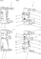
- Fig. 2 shows the one in the first door compartment 18 of the functional unit 1 of Fig. 1 arranged displacement device 10 with a holding device 4 according to Fig. 6 or Fig. 7 (in Fig. 2 shown schematically), from which the mounting profile 14 is held displaceably in a vertical orientation.
- the mounting profile 14, which is held in a vertical orientation by the holding device 4 and which is connected to the folding sliding door 11 by the stop hinges 131, is connected to a drive device 2 and to an auxiliary drive 3.
- the mounting profile 14 can be moved along a travel path S between a first end position S1 on the back of the door compartment 18 and a second end position S2 on the front of the door compartment 18.
- the mounting profile 14 is connected at the upper end to an upper guide drive 5, which is guided in an upper guide rail 15, and at the lower end by a lower guide drive 6, which is guided in a lower guide rail 16.
- the upper guide drive 5 includes support rollers 591 and guide rollers 592 and, in addition to the guide functions, also has a carrying function.
- the lower guide drive 6 includes guide rollers 692 which are guided in the lower guide rail 16.
- the upper guide drive 5 and the lower guide drive 6 lie in Fig. 2 at the second end position S2 on an upper stop device 7 and on a lower stop device 8, which will be described below with reference to Fig. 6 and Fig. 8a and Fig. 8b be explained in more detail.
- a stop device 90 with a stop or a stop plate 9 is provided on the rear first end position S1, which limits the travel path S of the mounting profile 14 on the back of the door compartment 18.
- the displacement device 10 preferably comprises a drive device 2 with a pull cable 22, which is in Fig. 2 not yet installed.
- the mounting profile 14 can preferably be moved over the entire travel path S.
- a drive device 2 with the same function or on the upper guide drive 5 is provided not only at the upper end of the mounting profile 14 or on the upper guide drive 5, but also at the lower end of the mounting profile 14 or on the lower guide drive 6.
- a functionally identical or identical drive device 2 is provided . What is desirable is a high acceleration at the beginning and then a uniform movement of the mounting profile 14.
- an auxiliary drive 3 is provided, by means of which the at least one drive device 2 is in the area of the rear first end position S1 is supported.
- the mounting profile 14 is released from the rear end position S1 or from the stop plate 9, it is additionally accelerated by the auxiliary drive 3 over a relatively short distance.
- a rapid movement sequence is achieved with the auxiliary drive 3.
- the mounting profile 14 does not move sluggishly from the end position S1, but is accelerated quickly.
- damping devices 99 which have a damping piston 991, which is displaced when it hits the stop plate 9 and dampens the movements of the mounting profile 14 and avoids a disruptive impact.
- a cyclically operating locking device 95 which includes an actuating rod 952 and a gripper 951, which can cooperate with a stationarily mounted gripping element 96 and which is activated by pressure on the actuating rod 952, which is activated when the first end position S1 is reached of the gripping element 96 is exercised, can be closed cyclically and released again (see Fig. 11 ). This can thus be locked by manually or motorically exerted pressure on the locking device 95 and unlocked again by further pressure.
- Fig. 2 also shows a retraction device E, by means of which the mounting profile 14 or one of the guide drives 5, 6 can be detected and pulled to the first end position S1.
- the holding device 4 according to the invention can therefore be used without or optionally in combination with one or more drive devices 2, E.
- Fig. 3 shows part of the displacement device 10 from Fig. 2 with the upper end piece of the mounting profile 14, which is connected to an upper guide drive 5, which is slidably mounted in an upper guide rail 15 and which is connected to a drive device 2.
- the drive device 2 comprises a drive unit 21 with a housing 210, in which a drive element 211 is provided and a pulley 212 connected thereto, onto which a pull rope 22 is wound, is rotatably held.
- the drive element 211 is preferably a driving spring, such as a spiral spring or a helical spring, which is tensioned or relaxed as the pulley 212 rotates.
- the pulley 212 is rotatably mounted by means of a bearing shaft 215 (shown schematically).
- the spiral-shaped drive element 211 also encloses the bearing shaft 215 and has a first end piece 2111 with the pulley 212 and a second End piece 2112 is firmly connected to the bearing shaft 215.
- the pulley 212 rotates when the pull rope 22 is pulled out, the first end piece 2111 of the drive element 211 is therefore guided around the bearing shaft 215, while the second end piece 2112 of the drive element 211 is held in place.
- the pulley 212 is turned back again by the tensioned drive element 211.
- the coupling element 221 is suspended at the end of the pull rope 22, for example on the front of a pull rope connection, and the mounting profile 14 is inserted into the door compartment 18, the pull rope 22 is pulled out of the drive unit 21, the pulley 212 is rotated and the drive element 211 is tensioned.
- the mounting profile 14 can now be locked with the locking device 95 when the second end position S2 is reached.
- the pulley 212 is turned back by the drive element 211 and the pull rope 22 is retracted and the mounting profile 14 is moved from the first end position S1 to the second end position S2.
- a door 11 connected to the mounting profile 14 is therefore automatically extended from the door compartment 18.
- the displacement device 10 can be installed in differently sized door compartments 18 without modification . As described below, adjustments and adjustments can be made with minimal effort. Even if the displacement device 10 is provided with a drive device 2 on the top of the mounting profile 14 and a drive device 2 on the underside of the mounting profile 14, the assembly of the displacement device 10 can be carried out with minimal effort.
- Fig. 3 also shows that the mounting profile 14 has two guide channels 141, 142 and a mounting channel 143, in which the stop hinges 131 are held in a form-fitting manner and can be fixed by locking screws 1311.
- At least one of the guide channels 141, 142 serves to hold a deflection unit 230, which can be moved along the mounting profile 14 and fixed at a suitable location using locking screws.
- the upper guide drive 5 comprises a two-part drive body 51 with a first drive body part 511 and a second drive body part 512, of which vertically aligned support rollers 591 and horizontally aligned guide rollers 592 are held.
- the two drive body parts 511, 512 can be connected to one another in one piece, but in this embodiment they are connected to one another by a coupling part 55.
- the support rollers 591 are supported on a running element 151 of the upper guide rail 15 and the guide rollers 592 are guided in a guide channel 152 of the upper guide rail 15.
- a buffer or damper 58 is inserted into the drive body 51.
- the upper guide drive 5 includes a stop part 53, which can cooperate with a buffer or damper on the front stop device 7.
- Fig. 4 shows the upper guide drive 5 of Fig. 3 from the other side and detached from the mounting profile 14, on which a deflection unit 230 with a first deflection roller 23 is held in a displaceable and fixable manner.
- the deflection unit 230 is held in a form-fitting manner in a guide channel 141 or 142 and can be moved along this and locked at a suitable location.
- the pull rope 22 of the drive device 2 is guided around the first deflection roller 23 to a second deflection roller 24, which is held by the drive body 51 of the upper guide drive. From the second deflection roller 24, the pull rope 22 is guided further to a pull rope connection 72, which is arranged on the upper stop device 7 (see Fig. 5 ).
- the path from the pull rope pulley 212 to the second deflection pulley 24 can be lengthened or shortened.
- a corresponding length of the pull cable 22 is pulled out of the drive unit 21, the pull cable pulley 212 is rotated accordingly and the drive element 211 is pretensioned accordingly.
- Pretensioning the drive element 211 therefore causes it to act on the traction cable 22 with a higher tensile force and the mounting profile 14 to be moved with a higher force from the first end position S1 towards the second end position S2. This setting can be easily made in just a few steps.
- Fig. 4 further shows that the first drive body part 511 has a downwardly directed mounting sword 5111, which can be inserted into a mounting opening 140 of the mounting profile 14. A part of the mounting profile 14 is held between the mounting sword 5111 and a holding plate 5112.
- the first drive body part 511 also holds a bearing shaft 415, from which a first upper roller unit 411 and a second upper roller unit 412 are rotatably supported.
- the first and second roller units 411, 412 the form a pair of rollers 41, are part of the holding device 4, which is explained below.
- a functional part 57 rests above the pair of rollers 41, which in Fig. 6 tethers 421, 422 shown.
- a damper channel 5120 is provided in the second drive body part 512, in which a drive damper 58 is arranged and fixed by means of a locking element, possibly a fixing screw 5121.
- Fig. 5 shows the upper part of the displacement device 10 from Fig. 2 with the drive device 2, from which the pull cable 22 is guided via the first deflection roller 23 of the deflection unit 230 which is slidably connected to the mounting profile 14 and the second deflection roller 24 connected to the upper guide carriage 5 to a pull cable connection 72 on the upper stop device 7, which is on the Front side of the upper guide rail 15 is held.
- the coupling part 221 is grasped at the end of the pull rope 2, guided around the first and second deflection rollers 23, 24 and hooked into the pull rope connection 72 of the upper stop device 7. This process can be carried out in just a few steps.
- the stop device 7 is equipped with a mounting beam 711 (see Fig. 8b ) held in a holding channel 157, which is provided on the underside of the running element 151 of the upper guide rail 15.
- a mounting beam 711 (see Fig. 8b ) held in a holding channel 157, which is provided on the underside of the running element 151 of the upper guide rail 15.
- Above the running element 151 is therefore the running technology with the support rollers 591 and the guide rollers 592 of the upper guide drive 5 (see Fig. 3 ) and an adjusting part 159 for adjusting the damper engagement depth, which can interact with the drive damper 58.
- the drive technology with the pull rope 22 and the holding technology of the holding device 4 with holding ropes 421, 422 are provided (see also Fig. 6 ).
- the stop device 7 includes a spacer roller 79 on one or both sides, on which the held door 11, which is shown in a sectional view, can roll without closing the body 71 of the stop device 7 touch.
- the upper stop device 7 includes a cable connection device 74, by means of which one of the retaining cables 421 of the retaining device 4 is held.
- a stop damper or stop buffer 78 is provided, which can interact with the stop part 53 of the upper guide drive 5 (see Fig. 4 ).
- Fig. 6 shows the displacement device 10 from Fig. 2 with a holding device 4 according to the invention, which comprises two holding ropes 421, 422.
- the upper guide drive 5 provided at the upper end of the mounting profile 14 is guided in the upper guide rail 15 and the lower guide drive 6 provided at the lower end of the mounting profile 14 is guided on a lower guide rail 16.
- the upper stop device 7 is shown on the front of the upper guide rail 15 and the lower stop device 8 is shown on the front of the lower guide rail 16 (see also Fig. 7 ).
- the guide rails 15, 16 are not shown.
- the upper front stop device 7 with the mounting beam 711, the pull rope connection 72 and the rope connection device 74 for the second tether 422 has already been described with reference to Fig. 5 explained.
- the rotary lever 75 serves to hold the mounting profile 14 in the front end position S2. In this position, the mounting profile 14 is held vertically aligned, so that the door 11 or the door elements 111, 112 can be mounted particularly easily.
- the upper cable connection device 74 includes a mounting channel 741 (see Fig. 8b ) with a subsequent recess into which an end piece of the upper retaining cable 422 can be inserted.
- the lower stop device 8 and the upper stop device 7 are referred to below Fig. 8a and Fig. 8b described.
- the second pull rope 422 is held in place by the pull rope connection 74 of the upper stop device 7.
- the pull cable connection 84 of the lower stop device 8 comprises an adjusting slide 842, which is slidably mounted and adjustable by means of an adjusting screw 845.
- An adjusting device 840 is formed by the adjusting screw 845 and the adjusting slide 842.
- the holding device 4 comprises a first front cable connection device 84, a first lower roller unit 431, which is arranged at the lower end of the mounting profile 14, a first upper roller unit 411, which is arranged at the upper end of the mounting profile 14, and a first rear cable connection device 44, which is arranged at the rear end of the upper guide rail 15, as well as the first tether 421, which is connected with a first end piece to the first front cable connection device 84, guided counterclockwise around the first lower roller unit 431 and clockwise around the first upper roller unit 411 and with a second end piece is connected to the first rear cable connection device 44.
- the holding device 4 comprises a second front cable connection device 74, a second upper roller unit 412, which is arranged at the upper end of the mounting profile 14, a second lower roller unit 432, which is arranged at the lower end of the mounting profile 14, and a second rear cable connection device 45, which is arranged at the rear end of the lower guide rail 16, as well as the second tether 422, which is connected with a first end piece to the second front cable connection device 74, guided clockwise around the second upper roller unit 412 and counterclockwise around the second lower roller unit 432 and with a second end piece is connected to the second rear cable connection device 45.
- the first front cable connection device 84 is provided at the front end of the lower guide rail 16 on the lower stop device 8.
- the second front cable connection device 74 is arranged at the front end of the upper guide rail 15 on the upper stop device 7.
- the second rear cable connection device 45 comprises a second tensioning device 450 with a second tension spring 453, which is connected, on the one hand, directly or via a second connection carriage 452 (shown in dash-dotted lines) to the second tether 422 and, on the other hand, to a second tension carriage 454, in which a stationary one is connected second tensioning screw 455 is screwed in, by means of which the second tension carriage 454 can be displaced within a second bearing profile 459 along its longitudinal axis in order to tension the second tension spring 453.
- the tension spring 453 is tensioned and a corresponding tensile force is transferred to the second retaining cable 422.
- one of the holding ropes in this embodiment the second holding rope 422, is therefore always held elastically.
- the first tether 421 is held inelastically or firmly by the first front cable connection device 84 and the first rear cable connection device 44.
- the vertical alignment of the mounting profile 14 can be carried out using the first adjusting device 840.
- the second tension spring 453 is prestressed or stretched by a predetermined amount. If the second tension spring 453 is connected on the one hand to the tension carriage 454 and on the other hand to the connection carriage 452 is, the amount of mutual displacement of the pulling carriage 454 and the connecting carriage 452 corresponds to the tensile force in the tension spring 453. The impressed tensile force can therefore be easily determined based on this displacement. When using a connection carriage 452, the tether 422 can be connected more easily, as described below.
- a tensile force is preferably also impressed into the first tether 421 before it is fixed.
- a tensile force is preferably also impressed into the first tether 421 before it is fixed.
- the preferably provided drive device 2 which is held by the upper guide carriage 5, was described with reference to Fig. 3 already described.
- the pull cable 22 of the drive device 2 is guided via the first deflection roller 23 and the second deflection roller 24 to the pull cable connection 72, which is provided on the upper front stop device 7.
- the deflection unit 230 is held in a form-fitting manner with a shaped element 232 in the first guide channel 141 and can be moved along the mounting profile 14.
- Fig. 7 shows the displacement device 10 from Fig. 6 with the two rear cable connection devices 44, 45 of the holding device 4, each of which has a bearing profile 449, 459 which is connected to the rear end piece of the upper or lower guide rail 15, 16.
- the bearing profiles 449, 459 have an elongated bearing opening 4490, 4590 through which the device parts are only partially visible.
- the device parts provided in the bearing profiles 449, 459, each of which includes a tension spring 443, 453, were therefore duplicated and shown separately.
- the tension springs 443, 453 are also shown separately.
- Each of the cable connection devices 44, 45 comprises an input roller 441, 451, a connection carriage 442, 452, a tension spring 443, 453, a tension carriage 444, 454, a tension screw 445, 455 and a screw holder 446, 456 anchored in the bearing profile 449, 459, by means of which holds the clamping screw 445, 455.
- the screw holders 446, 456 are each secured by means of a month screw 4461 with the associated bearing profile 449; 459 connected.
- the facing end piece of the associated tether 421, 422 is guided via the input roller 441, 451 to the connecting carriage 442, 452, which is connected by the tension spring 443, 453 to the tension carriage 444, 454, which in turn is connected to the screw holder by the tension screw 445, 455 446, 456 is connected.
- the tension spring 443, 453 is tensioned.
- the tensile force exerted by the tension spring 443, 453 is transmitted to the connected tether 421, 422 via the connecting carriage 442, 452.
- the parts of the cable connection devices 44, 45 mentioned therefore form tensioning devices 440, 450, by means of which a tensile force in the retaining cables 421, 422 can be adjusted.
- connection carriage 452 in the second cable connection device 45 is only provided as an option.
- the connection carriage 442 is always present so that the first traction cable 421 can be fixed after the tensile force has been impressed.
- a fixing screw 448 is provided in the connecting carriage 442 of the first rear cable connection device 44, which is passed through the profile opening 4490 in the bearing profile 449 and is clamped to the bearing profile 449 when tightened. Parts of the bearing profile 449 are therefore shown symbolically below the fixing screw 448.
- a predetermined tensile stress is impressed in the second tether 422 and the mounting profile 14 is vertically aligned by means of the tensioned first tether 421.
- This installation process is optimized by impressing a predetermined tensile force in the first retaining cable 421 before the adjustment or vertical alignment of the mounting profile 14. After impressing a predetermined tensile force in both retaining cables 421, 422, the effort required to adjust or vertically align the mounting profile 14 is reduced.
- the first tether 421 is additionally connected in the first rear cable connection device 44 to the first connection carriage 442, after which the first tension screw 445 is rotated and the first tension carriage 444 and the first connection carriage 442 are connected to one another by the first tension spring 443 are to be shifted relative to one another by a predetermined amount.
- the predetermined tensile forces are impressed in both pull ropes 421, 422. These adjustments are preferably made taking into account the measuring rods, which determine the extent of the mutual displacement of the Display the connection carriage 442, 452 and the pull carriage 444, 454 preferably on a scale with markings, if necessary color markings.
- the first connecting carriage 442 is fixed to the associated first bearing profile 449 after the predetermined tensile stress has been impressed.
- the first front adjusting device 840 is then actuated, as described, in order to vertically align the no longer fixed mounting profile 14. Usually only minimal corrections are necessary.
- a second drive device 2' and a second displaceably mounted deflection unit with a first deflection roller 23' can also be provided on the underside of the mounting profile 14.
- the lower pull rope would in turn be guided via the first deflection roller 23 'and a deflection roller which is attached, for example, to the lower guide drive 6 to a pull cable connection 82 on the lower stop device 8.
- Fig. 8a shows the upper stop device 7 and the lower stop device 8 from Fig. 7 in spatial representation.
- Fig. 8b shows the upper stop device 7 and the lower stop device 8 from Fig. 7 in sectional view.
- the upper stop device 7 and the lower stop device 8 each have a device body 71, 81 and a mounting beam 711, 811 formed thereon, which can be locked in the associated upper or lower guide rail 15, 16 by means of locking screws 712, 812.
- the upper stop device 7 has a hook-shaped pull rope connection 72, in which the coupling part 221 of the pull rope 22 can be suspended.
- each stop device 7, 8 preferably has a spacer roller 79, 89 on both sides, which keeps the passing door 11 at a distance, and a rotatable locking lever 75, 85, by means of which the mounting profile 14 can be fixed at the front in order to carry out installation work, maintenance work or adjustments .
- the locking lever 85 could also be used as a pull cable connection 82.
- the locking levers 75, 85 are held by a holding shell 710, 810, which is connected to the device body 71, 81 by a screw.
- each stop device 7, 8 has a preferably adjustable stop buffer 78, 88 with a buffer body 781, 881 and an adjusting screw 782, 882.
- the cable connection device 74 of the upper stop device 7 is designed simply and has a holding block 742 with an upwardly open mounting channel 741 into which an end piece of the second holding cable 422 can be hung.
- the lower stop device 8 includes a cable connection device 84 with an adjusting device 840, which is formed by a displaceable adjusting slide 842 and an adjusting screw 845, by means of which the adjusting slide 842 can be displaced within a bearing profile 843.
- the adjusting carriage 842 has a mounting channel 841 into which the end piece of the first retaining cable 421 can be hung.
- the lower stop device 8 has a plunger 86, which is axially displaceable by means of an adjusting screw 861 and which can interact with the integrated drive damper 68 of the lower guide drive 6.
- Fig. 9a shows the upper rear cable connection device 44 and Fig. 9b shows the lower rear cable connection device 45, which is related to Fig. 7 have already been briefly described.
- the input roller 441 of the upper rear cable connection device 44 is held by a roller holder 4411, which can be clamped within the bearing profile 449 by means of a tensioning element 4412.
- the input roller 451 of the lower rear cable connection device 45 is held by a roller holder 4511, which can be clamped within the bearing profile 459 by means of a tensioning element 4512.
- the optional connecting carriages 442, 452 have clamping jaws 4421, 4422 or 4521, 4522, which can be pressed against each other by clamping screws 4423, 4523 in order to fix the end piece of the relevant tether 421, 422 inserted between them.
- the retaining ropes 421, 422 can therefore be pulled through the connecting carriages 442, 452, tensioned and fixed manually.
- the fixing screw 448 by means of which the first connecting carriage 442 can be fixed to the associated first bearing profile 449. After fixing the first connection carriage 442, the first Tension spring 443 no longer has a relevant effect. The elasticity of the holding device 4 subsequently determines the tension spring 453 of the second cable connection device 45, which is still active.
- the mentioned parts of the cable connection devices 44, 45 form tensioning devices 440, 450, by means of which a tensile force in the retaining cables 421, 422 can be adjusted.
- a measuring rod 447, 457 with a control window 4570 is provided to set a desired tensile force.
- the measuring rod 457 is connected to the connecting carriage 452 and overlaps a scale 4471, 4571 which is provided on the pulling carriage 444, 454.
- the mutual displacement of the connecting carriage 442, 452 and the pulling carriage 444, 454, which are slidably mounted in the bearing profile 449, 459, can therefore be read using the measuring rod 447, 457.
- Fig. 10 shows the auxiliary drive 3 of Fig. 2 , which is held by the mounting profile 14 and which interacts with a rear end stop 9 after the sliding door 11 has been pushed into the door compartment 18.
- the auxiliary drive 3 comprises a housing 33 and at least one extendable piston 32, which is supported by a spring element 31 and which rests on the end stop 9 after the mounting profile 14 has entered the door compartment 18.
- the spring element 31 of the auxiliary drive 3 is tensioned as soon as the mounting profile 14 moves towards the first end position S1 within the door compartment 18. After reaching the end position, the spring element 31 of the auxiliary drive 3 is loaded and can support the drive device 2 at the beginning of the exit of the mounting profile 14 towards the second end position S2.
- the mounting profile 14 is also connected to a cyclically operating locking device 95, which includes an actuating rod 952 and a gripper 951, which cooperate with a stationary mounted gripping element 96 and can be closed and released cyclically by pressing on the actuating rod 952.
- the gripper 951 is closed by a first displacement of the actuating rod 952, which is arranged in a device housing 953 and supported by a spring, and the gripper 951 is opened again by a second displacement of the actuating rod 952.
- the actuating rod 952 is preferably arranged coaxially to the central axis of the gripper 951, so that the actuating rod 952 can be actuated by the gripping element 96, which is gripped by the gripper 951 and released again.
- the gripping element 96 is arranged on the stop plate 9 of the stop device 90, which is attached to the intermediate wall 1D functional unit 1.
- the displacement path of the actuating rod 952 is shown by a dash-dotted line. Shortly before reaching At the end position S1 it hits the gripping element 96 and is pushed back by it, whereby the gripping device 95 is actuated and coupled to the gripping element 96.
- damping devices 99 with damping pistons 991 are provided, which hit the stop plate 9 as soon as the mounting profile 14 reaches the end position S1.
- auxiliary drive 3, the gripping device 95 and the damping devices 99 are optionally provided and can be replaced by functionally identical devices.
- Fig. 11 shows a mounting configuration of the displacement device 10, which has a mounting profile set 14 ', which releasably holds the upper guide drive 5 and the lower guide drive 6, an upper guide rail set 15', which releasably holds the upper stop device 7 and the first rear cable connection device 44 and with the upper guide drive 5 is connected, a lower guide rail replacement 16 ', which releasably holds the lower stop device 8 and the second rear cable connection device 45 and is connected to the lower guide carriage 6, as well as the pre-assembled tethers 421, 422.
- the retaining ropes 421, 422 are connected at the front to the rope connection devices 74, 84 of the stop devices 8, 7 and at the rear to the rope connection devices 44, 45.
- Fig. 11 also shows one of the partition walls 1D of Fig. 1 , on which the lower and upper guide rails 15, 16 are already mounted and to which the displacement device 10 present in the mounting configuration is transferred. Installation is particularly easy if the partition 1D is aligned horizontally.
- the assembly configuration of the displacement device 10 can therefore advantageously be created by the manufacturer during the installation of the Displacement device 10 at the installation site can be carried out by the user in a simple manner with almost no instructions, for example with the installation steps described below.
- the mounting profile set 14' is replaced by the mounting profile 14 in a first installation step.
- the guide drives 5, 6, which are now connected to the mounting profile 14, are inserted into the associated upper or lower guide rails 15, 16, which are connected to the intermediate wall 1D.
- the stop devices 7, 8 are detached from the upper and lower guide rail replacements 15', 16' and inserted into the upper and lower guide rails 5, 6.
- the mounting beam 711 of the upper stop device 7 is inserted into the mounting channel 153 of the upper guide rail 5 and the mounting beam 811 of the lower stop device 8 is inserted into the mounting channel 163 of the lower guide rail.
- the rear cable connection devices 44, 45 are detached from the upper and lower guide rail replacements 15', 16' and connected to the upper and lower guide rails 5, 6.
- a mounting strip 4495 of the first rear cable connection device 44 is screwed to a mounting connection 154 of the upper guide rail 15.
- the second rear cable connection device 45 is inserted into the mounting channel 163 of the lower guide rail 16 with a mounting beam 45111, which is connected to the associated roller holder 4511.
- the upper guide rail replacement 15' is detached from the upper guide track 5 and the lower guide rail replacement 16' is detached from the lower guide drive 6.
- the displacement device 10 is connected solely to the upper and lower guide rails 15, 16.
Abstract
Verschiebevorrichtung (10), die für die Installation in einem Türfach (18) einer Funktionseinheit (1) vorgesehen ist, umfasst ein stabförmiges Montageprofil (14), das von einer Haltevorrichtung (4) senkrecht ausgerichtet gehalten zwischen einer ersten Endposition (S1) und einer zweiten Endposition (S2) eines Fahrwegs (S) verschiebbar und durch Anschlagscharniere (131) mit einer einteiligen oder mehrteiligen Tür (11) verbunden oder verbindbar ist. Die Haltevorrichtung (4) umfasst erste und zweite frontseitige Seilanschlussvorrichtungen (74, 84) und erste und zweite rückseitige Seilanschlussvorrichtungen (44, 45) die durch erste und zweite Halteseile (421, 422) miteinander verbunden sind. Erfindungsgemäss umfasst die zweite rückseitige Seilanschlussvorrichtung (45) eine zweite Spannvorrichtung (450) mit einem zweiten Anschlussschlitten (452), der einerseits mit dem zugehörigen zweiten Halteseil (422) verbunden ist und der andererseits durch eine zweite Zugfeder (453) mit einem zweiten Zugschlitten (454) verbunden ist, in den eine ortsfest gehaltene zweite Spannschraube (455) eingedreht ist, mittels der der zweite Zugschlitten (454) und der zweite Anschlussschlitten (452) innerhalb eines zweiten Lagerprofils (459) entlang dessen Längsachse gegeneinander verschiebbar sind; wobei die erste frontseitige Seilanschlussvorrichtung (84) eine erste Stellvorrichtung (840) mit einem ersten Stellschlitten (842) umfasst, der einerseits mit dem fixierten ersten Halteseil (421) verbunden ist und der andererseits mit einer ortsfest gehaltenen Stellschraube (845) zusammenwirkt, die im ersten Stellschlitten (842) drehbar gehalten ist.Displacement device (10), which is intended for installation in a door compartment (18) of a functional unit (1), comprises a rod-shaped mounting profile (14), which is held vertically aligned by a holding device (4) between a first end position (S1) and a second end position (S2) of a travel path (S) is displaceable and connected or connectable to a one-piece or multi-part door (11) by stop hinges (131). The holding device (4) comprises first and second front cable connection devices (74, 84) and first and second rear cable connection devices (44, 45) which are connected to one another by first and second holding cables (421, 422). According to the invention, the second rear cable connection device (45) comprises a second tensioning device (450) with a second connection carriage (452), which on the one hand is connected to the associated second retaining cable (422) and on the other hand is connected to a second tension carriage (453) by a second tension spring (453). 454) is connected, into which a stationary second clamping screw (455) is screwed, by means of which the second pulling carriage (454) and the second connecting carriage (452) can be displaced relative to one another within a second bearing profile (459) along its longitudinal axis; wherein the first front cable connection device (84) comprises a first adjusting device (840) with a first adjusting carriage (842), which on the one hand is connected to the fixed first tether (421) and which, on the other hand, cooperates with a stationary adjusting screw (845), which is in first adjusting slide (842) is rotatably held.
Description
Die Erfindung betrifft eine Verschiebevorrichtung mit einem Montageprofil, das verbunden mit einer einteiligen oder mehrteiligen Tür, gegebenenfalls einer Faltschiebetür, senkrecht ausgerichtet vorzugsweise selbsttätig innerhalb eines Türfachs verschiebbar ist, eine Funktionseinheit, insbesondere ein Möbelstück oder eine Raumeinheit, mit wenigstens einer Verschiebevorrichtung, sowie ein Verfahren zur Installation der Verschiebevorrichtung innerhalb der Funktionseinheit.The invention relates to a displacement device with a mounting profile, which is connected to a one-piece or multi-part door, possibly a folding sliding door, vertically aligned and preferably automatically displaceable within a door compartment, a functional unit, in particular a piece of furniture or a room unit, with at least one displacement device, and a method for installing the displacement device within the functional unit.
Zum Abschliessen von Öffnungen von Funktionseinheiten, wie Möbelstücken, Raumeinheiten, Küchen oder Schlafecken, werden oft einteilige oder mehrteilige Türen, gegebenenfalls Faltschiebetüren verwendet, die nach der Freigabe der Öffnung in ein Türfach der Funktionseinheit verschoben werden, um nicht störend in Erscheinung zu treten.To close openings of functional units, such as pieces of furniture, room units, kitchens or sleeping areas, one-piece or multi-part doors, possibly folding sliding doors, are often used, which are moved into a door compartment of the functional unit after the opening has been released in order not to appear disruptive.
Die
Die
Bei den genannten Verschiebevorrichtungen wird das Montageprofil mit der Schiebetür manuell in das Türfach eingeschoben und manuell aus dem Türfach wieder herausgezogen. Bekannt sind ferner Verschiebevorrichtungen, bei denen ein mit einer Schiebetür verbundenes Montageprofil mittels einer Antriebsvorrichtung selbsttätig innerhalb eines Türfachs verschiebbar ist.With the displacement devices mentioned, the mounting profile with the sliding door is manually pushed into the door compartment and manually pulled out of the door compartment again. Displacement devices are also known in which a mounting profile connected to a sliding door can be automatically moved within a door compartment by means of a drive device.
Die
Die
Die zuletzt beschriebenen Verschiebevorrichtungen weisen zum selbsttätigen Verschieben des Montageprofils eine Antriebsvorrichtung auf, die entweder mit speziell ausgebildete Haltevorrichtungen zusammenwirken und in diese zu integrieren sind, oder die als separate Antriebsvorrichtungen nahe einem Endanschlag des Montageprofils dieses erfassen und in die Endpositionen ziehen. Die separaten Antriebsvorrichtungen benötigen in der Regel viel Raum und sind nur in der Lage, das Montageprofil über eine kurze Distanz zu fördern. Diese Antriebsvorrichtungen sind zudem relativ teuer und nur in vorgegebenen Grössen erhältlich.The displacement devices described last have a drive device for automatically moving the mounting profile, which either cooperate with specially designed holding devices and are to be integrated into them, or which, as separate drive devices, capture the mounting profile near an end stop and pull it into the end positions. The separate drive devices usually require a lot of space and are only able to convey the mounting profile over a short distance. These drive devices are also relatively expensive and only available in specified sizes.
Die Antriebsvorrichtungen und die weiteren Elemente der Verschiebevorrichtungen sind daher aneinander anzupassen und somit wesentlichen Restriktionen unterworfen. Zu beachten ist, dass innerhalb des Türfachs, das gegebenenfalls zur Aufnahme mehr als eines Türelements vorgesehen ist, normalerweise wenig Raum vorhanden ist, weshalb die Restriktionen bei der Integration der Antriebsvorrichtung in die Verschiebevorrichtung besonders kritisch ist.The drive devices and the other elements of the displacement devices must therefore be adapted to one another and are therefore subject to significant restrictions. It should be noted that there is usually little space within the door compartment, which may be intended to accommodate more than one door element, which is why the restrictions when integrating the drive device into the displacement device are particularly critical.
Die
Nachteilig bei dieser Vorrichtung ist, dass die Funktion der Haltevorrichtung wesentlich von der Einstellung der Seilspannungen abhängt. Sofern die Seilspannungen nicht korrekt eingestellt sind, wird das Montageprofil möglicherweise nicht korrekt gehalten oder es können Blockierungen auftreten. Zudem ist zu beachten, dass Installationen der Verschiebevorrichtung am Installationsort von unterschiedlichen Installateuren durchgeführt werden. Dabei resultieren jeweils unterschiedliche Einstellungen, welche die Funktion der Verschiebevorrichtung beeinträchtigen und Wartungseinsätze zur Folge haben.The disadvantage of this device is that the function of the holding device depends largely on the adjustment of the rope tensions. If the rope tensions are not set correctly, the mounting profile may not be held correctly or blockages may occur. It should also be noted that installations of the displacement device are carried out by different installers at the installation site. This results in different settings, which impair the function of the displacement device and result in maintenance work.
Bei Krafteinwirkungen können zudem übermässige Belastungen in nicht optimal installierten Verschiebevorrichtungen auftreten, welche Schäden verursachen und Nachjustierungen erfordern können.When forces are applied, excessive loads can also occur in shifting devices that are not optimally installed, which can cause damage and require readjustments.
Selbst bei optimaler Einstellung der Verschiebevorrichtung besteht das Problem, dass bei Krafteinwirkungen auf die Verschiebevorrichtung Blockierungen auftreten können.Even if the displacement device is optimally adjusted, there is the problem that blockages can occur when force is applied to the displacement device.
Der vorliegenden Erfindung liegt daher die Aufgabe zugrunde, eine verbesserte Verschiebevorrichtung zu schaffen, mittels der ein Montageprofil, das mit einer einteiligen oder mehrteiligen Tür verbunden oder verbindbar ist, senkrecht ausgerichtet innerhalb eines Türfachs einer Funktionseinheit, eines Möbelstücks oder einer Raumeinheit, verschiebbar ist. Weiterhin ist ein Verfahren zur Installation der Verschiebevorrichtung anzugeben. Ferner ist eine Funktionseinheit, ein Möbelstück oder eine Raumeinheit, mit wenigstens einer verbesserten Verschiebevorrichtung zu schaffen, mittels der ein mit einer Tür, gegebenenfalls einer Faltschiebetür verbundenes Montageprofil innerhalb eines Türfachs der Funktionseinheit vorteilhaft verschiebbar ist.The present invention is therefore based on the object of creating an improved displacement device, by means of which a mounting profile, which is connected or connectable to a one-piece or multi-part door, can be displaced vertically aligned within a door compartment of a functional unit, a piece of furniture or a room unit. Furthermore, a method for installing the displacement device must be specified. Furthermore, a functional unit, a piece of furniture or a room unit, is to be created with at least one improved displacement device, by means of which a mounting profile connected to a door, possibly a folding sliding door, can be advantageously displaced within a door compartment of the functional unit.
Die Verschiebevorrichtung soll kompakt aufgebaut und einfach montierbar sein und nur wenig Raum in Anspruch nehmen, sodass innerhalb des Türfachs der Funktionseinheit viel Raum freigehalten werden kann und das Türfach mit reduzierten Dimensionen realisiert werden kann.The displacement device should have a compact structure and be easy to assemble and take up little space, so that a lot of space can be kept free within the door compartment of the functional unit and the door compartment can be realized with reduced dimensions.
Die Verschiebevorrichtung soll einfach und präzise justierbar sein, sodass die Verschiebevorrichtung unabhängig vom jeweiligen Installateur stets optimal eingestellt ist.The displacement device should be easily and precisely adjustable so that the displacement device is always optimally adjusted, regardless of the installer.
Die Verschiebevorrichtung soll auch bei unerwünschten Krafteinwirkungen zuverlässig funktionieren und keinen Belastungen ausgesetzt werden, die Schäden nach sich ziehen können. Die Verschiebevorrichtung soll robust und belastbar sein. Wartungsarbeiten und Nachjustierungen sollen auch bei hoher Beanspruchung und Belastung weitgehend vermieden werden.The displacement device should function reliably even in the event of undesirable forces and should not be exposed to any loads that could cause damage. The displacement device should be robust and resilient. Maintenance work and readjustments should be largely avoided, even under high stress and strain.
Vorzugsweise soll das Montageprofil der Verschiebevorrichtung innerhalb des Türfachs selbsttätig verschiebbar sein, sodass eine montierte Tür selbsttätig in das Türfach eingefahren oder selbsttätig aus dem Türfach ausgestossen wird.Preferably, the mounting profile of the displacement device should be able to be moved automatically within the door compartment, so that a mounted door is automatically retracted into the door compartment or automatically ejected from the door compartment.
Diese Aufgabe wird mit einer Verschiebevorrichtung gemäss Anspruch 1, einem Verfahren zur Installation dieser Verschiebevorrichtung gemäss Anspruch 13 und einer verbesserten Funktionseinheit gemäss Anspruch 16, die wenigstens ein Türfach mit einer darin angeordneten Verschiebevorrichtung gemäss Anspruch 1 aufweist, gelöst. Vorteilhafte Ausgestaltungen der Erfindung sind in weiteren Ansprüchen angegeben.This object is achieved with a displacement device according to
Die Verschiebevorrichtung, die für die Installation in einem Türfach einer Funktionseinheit vorgesehen ist, umfasst ein stabförmiges Montageprofil, das von einer Haltevorrichtung senkrecht ausgerichtet gehalten zwischen einer ersten Endposition und einer zweiten Endposition eines Fahrwegs verschiebbar und durch Anschlagscharniere mit einer einteiligen oder mehrteiligen Tür verbunden oder verbindbar ist.The displacement device, which is intended for installation in a door compartment of a functional unit, comprises a rod-shaped mounting profile, which is held vertically aligned by a holding device and is displaceable between a first end position and a second end position of a travel path and is connected or connectable to a one-piece or multi-part door by stop hinges is.
Die Haltevorrichtung umfasst
- eine erste frontseitige Seilanschlussvorrichtung, eine erste untere Rolleneinheit, die an einem unteren Ende des Montageprofils angeordnet ist, eine erste obere Rolleneinheit, die an einem oberen Ende des Montageprofils angeordnet ist, und eine erste rückseitige Seilanschlussvorrichtung, sowie ein erstes Halteseil, das mit einem ersten Endstück mit der ersten frontseitigen Seilanschlussvorrichtung verbunden, vorzugsweise im Gegenuhrzeigersinn um die erste untere Rolleneinheit und vorzugsweise im Uhrzeigersinn um die erste obere Rolleneinheit geführt und mit einem zweiten Endstück mit der ersten rückseitigen Seilanschlussvorrichtung verbunden ist; und
- eine zweite frontseitige Seilanschlussvorrichtung, eine zweite obere Rolleneinheit, die am oberen Ende des Montageprofils angeordnet ist, eine zweite untere Rolleneinheit, die am unteren Ende des Montageprofils angeordnet ist, und eine zweite rückseitige Seilanschlussvorrichtung, sowie ein zweites Halteseil, das mit einem ersten Endstück mit der zweiten frontseitigen Seilanschlussvorrichtung verbunden, vorzugsweise im Uhrzeigersinn um die zweite obere Rolleneinheit und vorzugsweise im Gegenuhrzeigersinn um die zweite untere Rolleneinheit geführt und mit einem zweiten Endstück mit der zweiten rückseitigen Seilanschlussvorrichtung verbunden ist.
- a first front cable connection device, a first lower roller unit, which is arranged at a lower end of the mounting profile, a first upper roller unit, which is arranged at an upper end of the mounting profile, and a first rear cable connection device, and a first tether which is connected to a first End piece connected to the first front cable connection device, preferably guided counterclockwise around the first lower roller unit and preferably clockwise around the first upper roller unit and connected with a second end piece to the first rear cable connection device; and
- a second front cable connection device, a second upper roller unit, which is arranged at the upper end of the mounting profile, a second lower roller unit, which is arranged at the lower end of the mounting profile, and a second rear cable connection device, and a second tether which has a first end piece connected to the second front cable connection device, preferably guided clockwise around the second upper roller unit and preferably counterclockwise around the second lower roller unit and connected with a second end piece to the second rear cable connection device.
Erfindungsgemäss umfasst die zweite rückseitige Seilanschlussvorrichtung eine zweite Spannvorrichtung mit einem zweiten Anschlussschlitten, der einerseits mit dem zugehörigen zweiten Halteseil verbunden ist und der andererseits durch eine zweite Zugfeder mit einem zweiten Zugschlitten verbunden ist, in den eine ortsfest gehaltene zweite Spannschraube eingedreht ist, mittels der der zweite Zugschlitten und der zweite Anschlussschlitten innerhalb eines zweiten Lagerprofils entlang dessen Längsachse gegeneinander verschiebbar sind; wobei die erste frontseitige Seilanschlussvorrichtung eine erste Stellvorrichtung mit einem ersten Stellschlitten umfasst, der einerseits mit dem fixierten ersten Halteseil verbunden ist und der andererseits mit einer ortsfest gehaltenen Stellschraube zusammenwirkt, die im ersten Stellschlitten drehbar gehalten ist.According to the invention, the second rear cable connection device comprises a second tensioning device with a second connection carriage, which on the one hand is connected to the associated second tether and which, on the other hand, is connected by a second tension spring to a second tension carriage, into which a stationary second tensioning screw is screwed, by means of which the second pulling carriage and the second connecting carriage can be displaced relative to one another within a second bearing profile along the longitudinal axis of the latter; wherein the first front cable connection device comprises a first adjusting device with a first adjusting slide, which on the one hand is connected to the fixed first tether and which, on the other hand, cooperates with a stationary adjusting screw which is rotatably held in the first adjusting slide.
Die beiden Halteseile der Haltevorrichtung, beispielsweise Seile aus Stahl, die gegebenenfalls mit Edelmetall und/oder Kunststoff beschichtet sind, halten das Montageprofil während der Verschiebung innerhalb des Türfachs stets in senkrechter Ausrichtung zu den Führungsschienen. Möglich ist eine kinematische Umkehr oder eine Spiegelung der beschriebenen Vorrichtungsteile.The two retaining cables of the holding device, for example steel cables, which may be coated with precious metal and/or plastic, always hold the mounting profile in a perpendicular orientation to the guide rails during displacement within the door compartment. A kinematic reversal or a mirroring of the device parts described is possible.
Erfindungsgemäss wird immer eines der Halteseile der Haltevorrichtung elastisch gehalten, während das andere Halteseil, das nicht elastisch gehalten ist, zur Justierung des Montageprofils verwendet wird. Durch das elastische Halten des zweiten Zugseils wird sichergestellt, dass keine Blockierungen auftreten. Einwirkende Stösse können elastisch aufgefangen werden, sodass keine übermässigen Belastungen der Verschiebevorrichtung auftreten. Die erfindungsgemässe Verschiebevorrichtung kann daher über eine längere Zeit wartungsfrei betrieben werden. Die Einstellung der frontseitigen Stellvorrichtung kann unmittelbar am Eingang des Türfachs in einfacher Weise vollzogen werden.According to the invention, one of the retaining ropes of the holding device is always held elastically, while the other retaining rope, which is not held elastically, is used to adjust the mounting profile. Holding the second pull rope elastically ensures that no blockages occur. Impacts can be absorbed elastically so that no excessive loads are placed on the displacement device. The displacement device according to the invention can therefore be operated maintenance-free for a longer period of time. The front adjusting device can be easily adjusted directly at the entrance to the door compartment.
Durch Betätigung der Stellvorrichtung wird der Anteil des ersten Halteseils, der in der Haltevorrichtung wirksam ist, verlängert oder verkürzt, wodurch die Neigung des Montageprofils eingestellt wird. Diese Einstellung wird durch die elastische Ankopplung des zweiten Halteseils begünstigt. Durch das erste Halteseil wird dabei verhindert, dass das Montageprofil unter Einwirkung des Gewichts der montierten Tür nach vorne zum Ausgang des Türfachs kippt.By actuating the adjusting device, the portion of the first tether that is effective in the holding device is lengthened or shortened, whereby the inclination of the mounting profile is adjusted. This setting is facilitated by the elastic coupling of the second tether. The first retaining rope prevents the mounting profile from tipping forward towards the exit of the door compartment under the influence of the weight of the mounted door.
Damit die Haltevorrichtung optimal funktioniert, wird die Zugkraft zumindest im elastisch gehaltenen Halteseil auf einen vorgegebenen Wert eingestellt. Vorzugsweise wird auch eine vorgegebene Zugkraft im ersten Halteseil eingestellt oder eingeprägt. Die in den Halteseilen eingestellten Zugkräfte sind vorzugsweise identisch.In order for the holding device to function optimally, the tensile force is set to a predetermined value, at least in the elastically held tether. Preferably, a predetermined tensile force is also set or impressed in the first tether. The tensile forces set in the retaining ropes are preferably identical.
Die Zugkraft soll dabei nicht zu gering, aber auch nicht zu hoch sein, damit einerseits Instabilitäten und andererseits Blockierungen oder Überbelastungen vermieden werden. Durch Betätigung der zweiten Spannvorrichtung kann der Zugschlitten gegenüber dem Anschlussschlitten verschoben werden, wodurch die Zugfeder gedehnt und eine Zugkraft auf das zweite Zugseil ausgeübt wird. Durch Prüfung des Verhaltens der Verschiebevorrichtung können optimale Werte für die Zugspannung bzw. die gegenseitige Verschiebung des Anschlussschlittens und des Zugschlittens bzw. der Dehnung der Zugfeder ermittelt werden. Für die Installation der Verschiebevorrichtung kann daher stets eine optimale gegenseitige Verschiebung des Zugschlittens und des Anschlussschlittens vorgegeben und eingestellt werden.The tensile force should not be too low, but also not too high, to avoid instabilities on the one hand and blockages or overloads on the other. By actuating the second tensioning device, the pulling carriage can be moved relative to the connecting carriage, whereby the tension spring is stretched and a tensile force is exerted on the second traction cable. By testing the behavior of the displacement device, optimal values for the tensile stress or the mutual displacement of the connecting carriage and the tension carriage or the elongation of the tension spring can be determined. When installing the displacement device, an optimal mutual displacement of the pulling carriage and the connecting carriage can always be specified and set.
In einer besonders bevorzugten Ausgestaltung ist daher vorgesehen, dass die erste rückseitige Seilanschlussvorrichtung eine erste Spannvorrichtung mit einem ersten Anschlussschlitten umfasst, der einerseits mit dem ersten Halteseil verbunden ist und der andererseits durch eine erste Zugfeder mit einem ersten Zugschlitten verbunden ist, in dem eine erste Spannschraube axial verschiebbar gehalten ist, mittels der der erste Zugschlitten und der erste Anschlussschlitten innerhalb eines ersten Lagerprofils entlang dessen Längsachse gegeneinander verschiebbar sind. Vorzugsweise weisen die erste und die zweite Spannvorrichtung identische Vorrichtungsteile auf.In a particularly preferred embodiment, it is therefore provided that the first rear cable connection device comprises a first tensioning device with a first connection carriage, which on the one hand is connected to the first tether and on the other hand is connected by a first tension spring to a first tension carriage in which a first tension screw is held axially displaceably, by means of which the first pulling carriage and the first connecting carriage can be displaced relative to one another within a first bearing profile along its longitudinal axis. Preferably, the first and second clamping devices have identical device parts.
In dieser vorzugsweisen Ausgestaltung können somit das erste und das zweite Halteseil mit einer vorgegebenen Zugkraft gespannt werden. Noch Einprägung der Zugkraft in das erste Halteseil wird der erste Anschlussschlitten gegenüber dem Lagergehäuse fixiert, wonach die vertikale Ausrichtung des Montageprofils durch Betätigung der Stellvorrichtung erfolgt, wie dies oben beschrieben wurde. Die Haltevorrichtung arbeitet daher stets mit einer optimalen Einstellung und optimalen Zugkräften in den Halteseilen.In this preferred embodiment, the first and second tethers can therefore be tensioned with a predetermined tensile force. By impressing the tensile force into the first tether, the first connecting carriage is fixed relative to the bearing housing, after which the vertical alignment of the mounting profile is carried out by actuating the adjusting device, as above was described. The holding device therefore always works with an optimal setting and optimal tensile forces in the holding ropes.
Zur Einstellung einer gewünschten Zugkraft in den Halteseilen ist in den Zugvorrichtungen vorzugsweise ein Messstab mit dem Zugschlitten verbunden, der den Anschlussschlitten überlappt und der die gegenseitige Verschiebung des Zugschlittens und des Anschlussschlittens anzeigt. Alternativ ist der Messstab mit dem Anschlussschlitten verbunden, der den Zugschlitten überlappt und der die gegenseitige Verschiebung des Zugschlittens und des Anschlussschlittens anzeigt.To set a desired tensile force in the retaining ropes, a measuring rod is preferably connected to the pulling carriage in the pulling devices, which overlaps the connecting carriage and which indicates the mutual displacement of the pulling carriage and the connecting carriage. Alternatively, the measuring rod is connected to the connection slide, which overlaps the pull slide and which indicates the mutual displacement of the pull slide and the connection slide.
Der Messstab umfasst vorzugsweise ein Kontrollelement, wie ein Kontrollfenster oder ein Zeiger, mittels dessen die Position auf dem Anschlussschlitten oder auf dem Zugschlitten angezeigt wird, die zur gegenseitigen Verschiebung des Anschlussschlittens und des Zugschlittens korrespondiert und die beim Kontrollelement abgelesen werden kann. Der vom Messstab überlappte Anschlussschlitten oder der Zugschlitten weist eine entsprechende Rasterung oder Färbung auf, welche die Ablesung erleichtert. Vorzugsweise sind Markierungen, wie Farben oder eine Skala vorgesehen. Die Spannschraube wird gedreht, bis das Kontrollelement die Markierung erreicht, die gemäss zuvor ermittelter Empfehlung einzustellen ist. Beispielsweise ist eine Tabelle vorgesehen, in der für unterschiedliche Dimensionen der gehaltenen Tür einzustellende Zugkräfte angegeben sind. Damit die gegenseitige Verschiebung des Anschlussschlittens und des Zugschlittens innerhalb des Lagerprofils ersichtlich ist, weist das Lagerprofil vorzugsweise wenigstens eine langgestreckte Profilöffnung auf.The measuring rod preferably comprises a control element, such as a control window or a pointer, by means of which the position on the connection carriage or on the pull carriage is displayed, which corresponds to the mutual displacement of the connection carriage and the pull carriage and which can be read from the control element. The connecting slide or the pull slide overlapped by the measuring rod has a corresponding grid or coloring that makes reading easier. Markings such as colors or a scale are preferably provided. The clamping screw is turned until the control element reaches the mark that is to be adjusted according to the previously determined recommendation. For example, a table is provided in which tensile forces to be set for different dimensions of the held door are specified. So that the mutual displacement of the connecting carriage and the pulling carriage within the bearing profile can be seen, the bearing profile preferably has at least one elongated profile opening.
Die Lagerprofile, an deren Eingang vorzugsweise eine Eingangsrolle vorgesehen ist, sind vorzugsweise senkrecht zu den Führungsschienen ausgerichtet. Auf diese Weise kann in den Lagerprofilen ein relativ langer Lagerkanal vorgesehen werden, welche erlaubt, den Anschlussschlitten und den zugehörigen Zugschlitten über eine weite Distanz bedarfsweise zu verstellen.The bearing profiles, at the entrance of which an input roller is preferably provided, are preferably aligned perpendicular to the guide rails. In this way, a relatively long bearing channel can be provided in the bearing profiles, which allows the connecting carriage and the associated pulling carriage to be adjusted over a long distance if necessary.
Die nachstehend beschriebene Installation der Verschiebevorrichtung kann besonders einfach vollzogen werden, wenn die erste frontseitige Seilanschlussvorrichtung oder die erste rückseitige Seilanschlussvorrichtung eine Klemmvorrichtung umfasst, mittels der das zugewandte erste oder zweite Endstück des ersten Halteseils festgeklemmt und gehalten werden kann, und/oder wenn die zweite frontseitige Seilanschlussvorrichtung oder die zweite rückseitige Seilanschlussvorrichtung eine Klemmvorrichtung umfasst, mittels der das zugewandte erste oder zweite Endstück des zweiten Halteseils festgeklemmt und gehalten werden kann. Aufgrund dieser Massnahmen ist es nicht erforderlich, dass die Halteseile exakt dimensioniert und beispielsweise mit Anschlussösen versehen werden müssen. Stattdessen können die Halteseile manuell eingelegt, manuell gespannt und festgeklemmt werden. Unabhängig von den Dimensionen der Verschiebevorrichtung kann die Installation der Halteseile vorteilhaft vollzogen werden. Anschliessend können die Halteseile vorzugsweise mittels der Spannfedern auf eine vorgegebene Zugkraft vorgespannt werden. Vorzugsweise sind die Klemmvorrichtungen in Form von Anschlussschlitten in den rückseitigen Seilanschlussvorrichtungen vorgesehen.The installation of the displacement device described below can be carried out particularly easily if the first front cable connection device or the first rear cable connection device comprises a clamping device by means of which the facing first or second end piece of the first tether can be clamped and held, and / or if the second front Cable connection device or the second rear cable connection device comprises a clamping device, by means of which the facing first or second end piece of the second tether can be clamped and held. Due to these measures, it is not necessary for the retaining ropes to be precisely dimensioned and, for example, to be provided with connection eyelets. Instead, the tethers can be inserted, tensioned and clamped manually. Regardless of the dimensions of the displacement device, the installation of the retaining ropes can be carried out advantageously. The retaining ropes can then be pretensioned to a predetermined tensile force, preferably by means of the tension springs. The clamping devices are preferably provided in the form of connecting carriages in the rear cable connecting devices.
In einer bevorzugten Ausgestaltung ist vorgesehen, dass das Montageprofil an einem oberen Endstück mit einem oberen Führungslaufwerk verbunden ist, das einen oberen Laufwerkskörper aufweist und das an einer oberen Führungsschiene verschiebbar gelagert ist; und/oder dass das Montageprofil an einem unteren Endstück mit einem unteren Führungslaufwerk verbunden ist, das einen unteren Laufwerkskörper aufweist und das an einer unteren Führungsschiene verschiebbar gelagert ist. Durch Verwendung eines oberen Führungslaufwerks und/oder eines unteren Führungslaufwerks werden Kräfte aufgenommen, die senkrecht auf das Montageprofil einwirken. Mittels der Haltevorrichtung sind daher nur Drehmomente aufzunehmen, die auf das Montageprofil einwirken.In a preferred embodiment it is provided that the mounting profile is connected at an upper end piece to an upper guide drive, which has an upper drive body and which is slidably mounted on an upper guide rail; and/or that the mounting profile is connected at a lower end piece to a lower guide drive, which has a lower drive body and which is slidably mounted on a lower guide rail. By using an upper guide drive and/or a lower guide drive, forces are absorbed that act vertically on the mounting profile. The holding device therefore only needs to absorb torques that act on the mounting profile.
Vorzugsweise ist vorgesehen, dass die erste frontseitige Seilanschlussvorrichtung am frontseitigen Ende der unteren Führungsschiene angeordnet von dieser gehalten ist, und/oder dass die erste rückseitige Seilanschlussvorrichtung am rückseitigen Ende der oberen Führungsschiene angeordnet und von dieser gehalten ist, und/oder dass die zweite frontseitige Seilanschlussvorrichtung am frontseitigen Ende der oberen Führungsschiene angeordnet und von dieser gehalten ist, und/oder dass die zweite rückseitige Seilanschlussvorrichtung am rückseitigen Ende der unteren Führungsschiene angeordnet. Auf diese Weise resultiert eine einfache und stabile Montage der Seilanschlussvorrichtungen. Mit einer Seitenwand der Funktionseinheit sind daher nur die Führungsschienen zu verbinden, während praktisch alle weiteren Teile der Verschiebevorrichtung, einschliesslich frontseitiger Anschlagvorrichtungen mit den Führungsschienen verbunden werden können.It is preferably provided that the first front cable connection device is arranged at the front end of the lower guide rail and is held by the latter, and / or that the first rear cable connection device is arranged at the rear end of the upper guide rail and is held by it, and / or that the second front cable connection device is arranged at the front end of the upper guide rail and held by it, and / or that the second rear cable connection device is arranged at the rear end of the lower guide rail. This results in a simple and stable installation of the cable connection devices. Therefore, only the guide rails need to be connected to a side wall of the functional unit, while practically all other parts of the displacement device, including front-side stop devices, can be connected to the guide rails.
Die vorzugsweise vorgesehen Antriebsvorrichtung ist ebenfalls mit dem Montageprofil oder einem der Führungslaufwerke verbunden. Die erfindungsgemässe Verschiebevorrichtung kann somit in ihrer Konfiguration besonders einfach in beliebige Türfächer eingebaut werden.The preferably provided drive device is also connected to the mounting profile or one of the guide drives. The configuration of the displacement device according to the invention can therefore be installed particularly easily in any door compartment.
Die erste untere Rolleneinheit und die zweite untere Rolleneinheit sind vorzugsweise koaxial zueinander ausgerichtet von einer unteren Lagerwelle gehalten, die mit dem unteren Laufwerkskörper des unteren Führungslaufwerks verbunden ist. Die erste obere Rolleneinheit und die zweite obere Rolleneinheit sind vorzugsweise koaxial zueinander ausgerichtet von einer oberen Lagerwelle gehalten, die mit dem oberen Laufwerkskörper des oberen Führungslaufwerks verbunden ist. Möglich ist auch eine Verbindung der Lagerwellen mit dem Montageprofil. Die Lagerwellen können jedoch in einfacher Weise in die Führungslaufwerke integriert werden. Zudem resultiert ein grösserer Abstand zwischen den beiden Lagerwellen. Die Rolleneinheiten können frei und unabhängig voneinander drehen, sodass die Verschiebung des Montageprofils reibungsfrei erfolgen kann. Dadurch wird auch gewährleistet, dass die selbsttätige Verschiebung mittels der wenigstens einen Antriebsvorrichtung effizient erfolgen kann.The first lower roller unit and the second lower roller unit are preferably held in coaxial alignment with one another by a lower bearing shaft which is connected to the lower drive body of the lower guide drive. The first upper roller unit and the second upper roller unit are preferably supported in coaxial alignment with one another by an upper bearing shaft connected to the upper track body of the upper guide track. It is also possible to connect the bearing shafts to the mounting profile. However, the bearing shafts can be easily integrated into the guide drives. This also results in a larger distance between the two bearing shafts. The roller units can rotate freely and independently of each other, so that the mounting profile can be moved smoothly. This also ensures that the automatic displacement can be carried out efficiently by means of the at least one drive device.
Die erfindungsgemässe Verschiebevorrichtung umfasst vorzugsweise wenigstens eine Antriebsvorrichtung, die ein Gehäuse aufweist, in der ein Antriebselement und ein Übertragungsmedium vorgesehen sind, mittels dessen eine Kraft vom Antriebselement auf das Montageprofil übertragbar ist.The displacement device according to the invention preferably comprises at least one drive device which has a housing in which a drive element and a transmission medium are provided, by means of which a force can be transferred from the drive element to the mounting profile.
Beispielsweise wird eine sogenannte Dämpfungs-/Einzugsvorrichtung eingesetzt, mittels der das Montageprofil oder ein damit verbundenes Teil erfasst und zu einem Endanschlag gezogen wird.For example, a so-called damping/retraction device is used, by means of which the mounting profile or a part connected to it is captured and pulled to an end stop.
In einer bevorzugten Ausgestaltung ist eine Antriebsvorrichtung mit dem Gehäuse mit dem Montageprofil oder einem der Führungslaufwerke fest verbunden und zusammen mit dem Montageprofil verschiebbar. Das Übertragungsmedium dieser Antriebsvorrichtung ist vorzugsweise ein Zugseil, welches von der Antriebsvorrichtung direkt oder über eine erste Umlenkrolle oder über die erste Umlenkrolle und eine zweite Umlenkrolle zu einem Zugseilanschluss geführt wird, der stationär an der ersten oder zweiten Endposition des Fahrwegs angeordnet bzw. mit einem Teil der Funktionseinheit verbunden ist.In a preferred embodiment, a drive device is firmly connected to the housing with the mounting profile or one of the guide drives and can be moved together with the mounting profile. The transmission medium of this drive device is preferably a traction cable, which is guided by the drive device directly or via a first deflection roller or via the first deflection roller and a second deflection roller to a traction cable connection, which is arranged stationary at the first or second end position of the travel path or with a part connected to the functional unit.
Mittels der Antriebsvorrichtung kann das Montageprofil selbsttätig in die eine Richtung gegen die erste Endposition oder in die andere Richtung gegen die zweite Endposition gefahren werden.By means of the drive device, the mounting profile can be automatically moved in one direction towards the first end position or in the other direction towards the second end position.
Die Antriebsvorrichtung bzw. das Gehäuse der Antriebsvorrichtung ist in Bezug auf die Verschiebungssachse des Montageprofils bzw. in Bezug auf den Fahrweg des Montageprofils vorzugsweise seitlich neben dem Montageprofil oder seitlich neben einem der Führungslaufwerke angeordnet. Diese Anordnung der Antriebsvorrichtung vermeidet eine Verkürzung des Fahrwegs. D.h., es wird vermieden, dass das Gehäuse der Antriebsvorrichtung auf einen Anschlag trifft, bevor eines der Führungslaufwerke oder das Montageprofil auf einen Anschlag trifft. Der Einsatz der Antriebsvorrichtung verursacht daher keine Einschränkung der Verschiebbarkeit des Montageprofils.The drive device or the housing of the drive device is preferably arranged laterally next to the mounting profile or laterally next to one of the guide drives in relation to the displacement axis of the mounting profile or in relation to the travel path of the mounting profile. This arrangement of the drive device avoids a shortening of the route. Ie, it will avoided that the housing of the drive device hits a stop before one of the guide drives or the mounting profile hits a stop. The use of the drive device therefore does not cause any restriction in the displaceability of the mounting profile.
Besonders vorteilhaft ist, dass die Antriebsvorrichtung verschiebbar mit dem Montageprofil oder einem Führungslaufwerk verbunden ist und nicht an einem Teil der Funktionseinheit innerhalb des Türfachs montiert werden muss, der kaum und gegebenenfalls erst nach Entfernung einer Rückwand oder Seitenwand der Funktionseinheit zugänglich ist. Ebenso wird die Wartung der Verschiebevorrichtung erleichtert. Sofern beispielsweise die Antriebsvorrichtung gewartet werden muss, so kann lediglich das Montageprofil zur Frontseite des Türfachs hingezogen werden, um in einfacher Weise auf die Antriebsvorrichtung zugreifen zu können.It is particularly advantageous that the drive device is slidably connected to the mounting profile or a guide drive and does not have to be mounted on a part of the functional unit within the door compartment that is hardly accessible and possibly only after removing a rear wall or side wall of the functional unit. Maintenance of the displacement device is also made easier. If, for example, the drive device needs to be serviced, only the mounting profile can be pulled towards the front of the door compartment in order to be able to easily access the drive device.
Die Antriebsvorrichtung kann auch ganz oder teilweise in das zugeordnete Führungslaufwerk integriert werden, sodass ein noch kompakterer Aufbau der Verschiebevorrichtung realisiert werden kann.The drive device can also be completely or partially integrated into the associated guide drive, so that an even more compact design of the displacement device can be realized.
In vorzugsweise Ausgestaltungen ist vorgesehen, dass das Antriebselement ein Federelement, eine Triebfeder, wie z.B. eine Schraubenfeder oder eine Spiralfeder ist, und dass das Zugseil auf eine Zugseilrolle aufgewickelt ist, die drehbar gelagert und mit dem Antriebselement verbunden ist, wobei durch Drehung der Zugseilrolle in die eine Richtung das Antriebselement spannbar und durch Drehung der Zugseilrolle in die andere Richtung das Antriebselement entspannbar ist.In preferred embodiments it is provided that the drive element is a spring element, a driving spring, such as a helical spring or a spiral spring, and that the traction cable is wound onto a traction cable pulley which is rotatably mounted and connected to the drive element, wherein by rotating the traction cable pulley in The drive element can be tensioned in one direction and the drive element can be relaxed by rotating the pulley pulley in the other direction.
Sofern eine erste Umlenkrolle vorgesehen ist, so ist diese vorzugsweise direkt oder indirekt mit dem Montageprofil oder mit einem der Führungslaufwerke verbunden. Auch eine zweite Umlenkrolle, sofern vorgesehen, ist vorzugsweise direkt oder indirekt mit dem Montageprofil oder mit einem der Führungslaufwerke verbunden. Auf diese Weise kann das Zugseil bedarfsweise geführt und die Verschiebevorrichtung noch immer kompakt aufgebaut werden. Das Zugseil wird nahe am Montageprofil geführt und umgelenkt, weshalb kein zusätzlicher Raum benötigt wird. Grundsätzlich ist es jedoch auch möglich, das Zugseil über eine Umlenkrolle zu führen, die gegebenenfalls nicht mit dem Montageprofil verbunden ist.If a first deflection roller is provided, it is preferably connected directly or indirectly to the mounting profile or to one of the guide drives. A second deflection roller, if provided, is preferably connected directly or indirectly to the mounting profile or to one of the guide drives. In this way, the pull rope can be guided if necessary and the displacement device can still be constructed in a compact manner. The pull rope is guided and deflected close to the mounting profile, which is why no additional space is required. In principle, however, it is also possible to guide the pull rope over a deflection pulley, which may not be connected to the mounting profile.
In vorzugsweise Ausgestaltungen ist vorgesehen, dass die erste Umlenkrolle in Bezug auf das Gehäuse der Antriebsvorrichtung und in Bezug auf die zweite Umlenkrolle verschiebbar gelagert ist und dadurch eine Vorspannung auf das Antriebselement übertragbar ist. Das Zugseil wird vorzugsweise vom Gehäuse der Antriebsvorrichtung zur ersten Umlenkrolle und vorzugsweise zumindest annähernd parallel zurück zur zweiten Umlenkrolle geführt.In preferred embodiments, it is provided that the first deflection roller is mounted displaceably with respect to the housing of the drive device and with respect to the second deflection roller and thereby a preload can be transferred to the drive element. The pull rope is preferably from the housing the drive device to the first deflection roller and preferably at least approximately parallel back to the second deflection roller.
Die erste Umlenkrolle ist vorzugsweise von einer Umlenkeinheit drehbar gehalten, die formschlüssig und/oder kraftschlüssig in einem Führungskanal des Montageprofils verschiebbar und arretierbar gehalten ist. Dies erlaubt es, die Verschiebevorrichtung vorteilhaft einzustellen, das Antriebselement vorzuspannen und an das Gewicht der einteiligen oder mehrteiligen Tür anzupassen, die mit dem Montageprofil verbunden ist. Die Umlenkeinheit ist vorzugsweise parallel zur Längsachse des Montageprofils verschiebbar und mit einer Fixierschraube in einer passenden Position fixierbar. Beispielsweise greift der Körper der Umlenkeinheit formschlüssig in den Führungskanal ein und wird mittels der Fixierschraube darin verspannt. Aufgrund der Länge des Führungskanals, der sich vorzugsweise über die gesamte Länge des Montageprofils erstreckt, resultiert ein entsprechend grosser Einstellbereich, der durch Verschiebung der Umlenkeinheit mit einer Handbewegung abgefahren werden kann.The first deflection roller is preferably rotatably held by a deflection unit, which is held in a form-fitting and / or non-positive manner in a guide channel of the mounting profile so that it can be moved and locked. This allows the displacement device to be adjusted advantageously, the drive element to be pretensioned and adapted to the weight of the one-piece or multi-piece door that is connected to the mounting profile. The deflection unit is preferably displaceable parallel to the longitudinal axis of the mounting profile and can be fixed in a suitable position with a fixing screw. For example, the body of the deflection unit engages in a form-fitting manner in the guide channel and is clamped therein by means of the fixing screw. Due to the length of the guide channel, which preferably extends over the entire length of the mounting profile, a correspondingly large adjustment range results, which can be traversed by moving the deflection unit with one hand movement.
Der Zugseilanschluss ist vorzugsweise an einer Anschlagvorrichtung angeordnet, die einen Anschlagpuffer umfasst und die in der oberen oder unteren Führungsschiene montiert ist und die einen Endanschlag für das obere oder untere Führungslaufwerk bildet.The pull cable connection is preferably arranged on a stop device which comprises a stop buffer and which is mounted in the upper or lower guide rail and which forms an end stop for the upper or lower guide carriage.
Vorzugsweise sind zwei Antriebsvorrichtungen vorgesehen, die mit dem Montageprofil oder je einem der Führungslaufwerke fest verbunden und zusammen mit dem Montageprofil verschiebbar sind, und die je ein Zugseil aufweisen, welches von der zugehörigen Antriebsvorrichtung direkt oder über eine erste Umlenkrolle oder über die erste Umlenkrolle und eine zweite Umlenkrolle zu einem zugehörigen Zugseilanschluss, der stationär an der ersten oder zweiten Endposition des Fahrwegs angeordnet ist, geführt und mit diesem verbunden ist.Preferably, two drive devices are provided, which are firmly connected to the mounting profile or one of the guide drives and can be moved together with the mounting profile, and which each have a pull cable, which is pulled from the associated drive device directly or via a first deflection roller or via the first deflection roller and a second deflection roller is guided to and connected to an associated pull cable connection, which is arranged stationary at the first or second end position of the travel path.
In einer weiteren vorzugsweisen Ausgestaltung ist vorgesehen, dass das Montageprofil mit einem Hilfsantrieb verbunden ist, der einen ausfahrbaren Kolben aufweist, der durch ein Federelement gestützt ist und der nach der Einfahrt des Montageprofils in das Türfach an einer Anschlagvorrichtung anliegt. Das Federelement des Hilfsantriebs wird gespannt, sobald das Montageprofil gegen die erste Endposition innerhalb des Türfachs fährt. Nach Erreichen der Endposition ist das Federelement des Hilfsantriebs geladen und kann die Antriebsvorrichtung zu Beginn der Ausfahrt des Montageprofils gegen die zweite Endposition unterstützen. Die Antriebsvorrichtung und der Hilfsantrieb, ergänzen sich daher ideal. Der Hilfsantrieb dient daher über eine kurze Strecke von 2 cm-10 cm der raschen Beschleunigung der Tür aus der Endposition, während der Hauptantrieb das Montageprofil weiter über den gesamten Fahrweg verschiebt.In a further preferred embodiment it is provided that the mounting profile is connected to an auxiliary drive which has an extendable piston which is supported by a spring element and which rests on a stop device after the mounting profile has entered the door compartment. The spring element of the auxiliary drive is tensioned as soon as the mounting profile moves towards the first end position within the door compartment. After reaching the end position, the spring element of the auxiliary drive is loaded and can support the drive device at the beginning of the extension of the mounting profile towards the second end position. The drive device and the Auxiliary drive therefore complement each other ideally. The auxiliary drive therefore serves to quickly accelerate the door from the end position over a short distance of 2 cm - 10 cm, while the main drive continues to move the mounting profile over the entire travel path.
Das Montageprofil ist vorzugsweise mit einer zyklisch arbeitenden Verriegelungsvorrichtung verbunden, die einen Betätigungsstab und einen Greifer umfasst, der mit einem stationär montierten Greifelement zusammenwirken und durch Druck auf den Betätigungsstab zyklisch verschliessbar und wieder lösbar ist. Durch eine erste Verschiebung des Betätigungsstabs, der von einer Feder gestützt ist, wird der Greifer verschlossen und durch eine zweite Verschiebung des Betätigungsstabs wird der Greifer wieder geöffnet. Der Betätigungsstab ist vorzugsweise koaxial zur Mittelachse des Greifers angeordnet, sodass der Betätigungsstab vom Greifelement betätigt werden kann, welches vom Greifer erfasst und wieder freigegeben wird.The mounting profile is preferably connected to a cyclically operating locking device, which comprises an actuating rod and a gripper, which cooperate with a stationary mounted gripping element and can be closed and released cyclically by pressing on the actuating rod. The gripper is closed by a first displacement of the actuating rod, which is supported by a spring, and the gripper is opened again by a second displacement of the actuating rod. The actuating rod is preferably arranged coaxially to the central axis of the gripper, so that the actuating rod can be actuated by the gripping element, which is gripped by the gripper and released again.
Vorzugsweise umfasst die Verriegelungsvorrichtung einen Verschlusskörper, der einseitig oder beidseitig eine Verschlussnut aufweist, in die je ein Verschlusselement eingreift. Die Verschlussnut umläuft vorzugsweise ein zentrales Verschlussteil und ist derart ausgebildet, dass das zugehörige Verschlusselement bei Bewegungen des Betätigungsstabs zyklisch in gleicher Richtung um das Verschlussteil herumgeführt wird und bei jedem Umlauf einmal in einen Rastbereich einrastet und aus dem Rastbereich wieder gelöst wird. Beim Erreichen der ersten Endposition innerhalb des Türfachs wird die Verriegelungsvorrichtung daher betätigt und vom Greifer gehalten. Durch einen Druck auf die montierte Tür wird der Betätigungsstab verschoben und der Greifer wieder gelöst. Die Tür kann daher innerhalb des Türfachs durch einen Druck verriegelt und durch einen weiteren Druck wieder gelöst werden.The locking device preferably comprises a locking body which has a locking groove on one or both sides, into which a locking element engages. The closure groove preferably runs around a central closure part and is designed in such a way that the associated closure element is guided cyclically in the same direction around the closure part when the actuating rod moves and engages once in a locking area with each revolution and is released again from the locking area. When the first end position within the door compartment is reached, the locking device is therefore actuated and held by the gripper. By pressing on the assembled door, the actuating rod is moved and the gripper is released again. The door can therefore be locked within the door compartment with one press and released again with another press.
Die erfindungsgemässe Verschiebevorrichtung kann für beliebige Funktionseinheiten eingesetzt werden, die einen abschliessbaren Raum umfassen, und die in der Regel durch Wände oder Zwischenwände begrenzt sind. Die Funktionseinheiten können durch Holzwände begrenzte Räume aufweisen und Möbelstücke, insbesondere Schränke, betreffen. Funktionseinheiten können hingegen auch durch Mauern begrenzte Räume aufweisen, die mittels einteiligen oder mehrteiligen Türen, gegebenenfalls Faltschiebetüren abschliessbar sind.The displacement device according to the invention can be used for any functional units that include a lockable space and that are usually limited by walls or partitions. The functional units can have rooms delimited by wooden walls and relate to pieces of furniture, especially cupboards. Functional units, on the other hand, can also have rooms delimited by walls, which can be locked using one-piece or multi-part doors, possibly folding sliding doors.
Die Haltevorrichtung kann in einfacher Weise an die Grösse des Türfachs angepasst werden und stets optimal mit dem Halteprofil zusammenwirken. Sofern in einem grösseren Türfach ein längeres Montageprofil über eine grössere Distanz zu verschieben ist, so sind lediglich längere Halteseile vorzusehen.The holding device can be easily adapted to the size of the door compartment and always works optimally with the holding profile. Provided If a longer mounting profile has to be moved over a greater distance in a larger door compartment, only longer retaining ropes need to be provided.
Die Halteseile können nahe bei den Führungsschienen geführt werden und verlaufen beim Wechsel von der oberen zur unteren Führungsschiene bzw. von der unteren zur oberen Führungsschiene vorzugsweise mit geringem Abstand zum Montageprofil. Bei diesen Richtungswechseln kreuzen sich die Halteseile typischerweise etwa in der Mitte des Montageprofils. Der Raum innerhalb des Türfachs wird dabei praktisch nur durch das stabförmigen Montageprofil in Anspruch genommen.The retaining ropes can be guided close to the guide rails and preferably run at a short distance from the mounting profile when changing from the upper to the lower guide rail or from the lower to the upper guide rail. During these changes of direction, the retaining cables typically cross each other approximately in the middle of the mounting profile. The space inside the door compartment is practically only taken up by the rod-shaped mounting profile.
Durch die Vermeidung eines Scherenkreuzes kann die erfindungsgemässe Verschiebevorrichtung kompakt aufgebaut werden. Das Türfach kann grössere einteilige oder mehrteilige Türen, gegebenenfalls Faltschiebetüren, die durch Anschlagscharniere mit dem Montageprofil verbunden sind, aufnehmen.By avoiding a scissor cross, the displacement device according to the invention can be constructed compactly. The door compartment can accommodate larger one-piece or multi-piece doors, possibly folding sliding doors, which are connected to the mounting profile by stop hinges.
Eine Funktionseinheit kann ein Türfach oder mehrere Türfächer aufweisen. Beispielsweise sind beidseits der Funktionseinheit Türfächer vorgesehen, die den Nutzraum der Funktionseinheit begrenzen. Ein Türfach kann zudem zwei Verschiebevorrichtungen mit einteiligen oder mehrteiligen Türen, gegebenenfalls Faltschiebetüren, aufweisen, mittels denen beidseits des Türfachs ein Nutzraum der Funktionseinheit abgeschlossen werden kann.A functional unit can have one door compartment or several door compartments. For example, door compartments are provided on both sides of the functional unit, which limit the usable space of the functional unit. A door compartment can also have two displacement devices with one-piece or multi-part doors, possibly folding sliding doors, by means of which a usable space of the functional unit can be closed off on both sides of the door compartment.
Nachfolgend wird die Erfindung anhand von Zeichnungen näher erläutert. Dabei zeigt:
- Fig. 1
- eine erfindungsgemässe Funktionseinheit 1 in der Ausgestaltung eines Möbelstücks mit einem ersten Türfach 18, in
dem ein Montageprofil 14 einer erfindungsgemässen Verschiebevorrichtung 10, das mit einerFaltschiebetür 11 verbunden ist und mittels einer Haltevorrichtung 4 verschiebbar gehalten ist, und einem zweiten Türfach 18, in demein weiteres Montageprofil 14 einer erfindungsgemässen Verschiebevorrichtung 10, das mit einer einteiligen Tür 11 verbunden ist, mittels einer Haltevorrichtung 4 verschiebbar gehalten ist; - Fig. 2
- die
im ersten Türfach 18der Funktionseinheit 1 vonFig. 1 angeordnete Verschiebevorrichtung 10mit dem Montageprofil 14, das optional mit einerAntriebsvorrichtung 2 und/oder optionalmit einem Hilfsantrieb 3 verbunden ist,das durch Anschlagscharniere 131mit der Faltschiebetür 11 verbunden ist und das von einer Haltevorrichtung 4 (schematisch gezeigt) in senkrechter Ausrichtung gehalten ist; - Fig. 3
- einen Teil der Verschiebevorrichtung 10 von
Fig. 2 mit dem oberen Endstück des Montageprofils 14, welches mit einem oberen Führungslaufwerk 5 verbunden ist, das in einer oberen Führungsschiene 15 verschiebbar gelagert ist und das mit einer vorzugsweise vorgesehenen Antriebsvorrichtung 2 verbunden ist, dieeine Seilrolle 212 hält, dievon einem Zugseil 22 umwickelt ist; - Fig. 4
das obere Führungslaufwerk 5 vonFig. 3 , von der anderen Seite und gelöst vom Montageprofil 14, andem eine Umlenkeinheit 230 mit einer ersten Umlenkrolle 23 verschiebbar und fixierbar gehalten ist, mit einem oberen Rollenpaar 41der Haltevorrichtung 4, das von einer oberen Lagerwelle 415 gehalten ist;- Fig. 5
- den oberen Teil der Verschiebevorrichtung 10 von
Fig. 2 mit einem ersten Halteseil 421der Haltevorrichtung 4 und der optionalen Antriebsvorrichtung 2, vonder ein Zugseil 22 über eine erste Umlenkrolle 23 einer verschiebbarmit dem Montageprofil 14verbundene Umlenkeinheit 230 und eine mitdem oberen Führungslaufwerk 5 verbundene zweite Umlenkrolle 24 zu einem Zugseilanschluss 72 an einer oberen Anschlagvorrichtung 7 geführt ist, die an der Frontseite der oberen Führungsschiene 15 gehalten ist; - Fig. 6
- die
Verschiebevorrichtung 10 vonFig. 2 mit der erfindungsgemässen Haltevorrichtung 4 in einer ersten vorzugsweisen Ausgestaltung mitdem ersten Halteseil 421, das mit einer ersten frontseitigen Seilanschlussvorrichtung 84 und einer ersten rückseitigen Seilanschlussvorrichtung 44 verbunden ist, und mit einem zweiten Halteseil 422, das mit einer zweiten frontseitigen Seilanschlussvorrichtung 74 und einer zweiten rückseitigen Seilanschlussvorrichtung 45 verbunden ist, in derdas zweite Halteseil 422 von einer gespannten zweiten Zugfeder 453 elastisch gehalten ist; - Fig. 7
- die
Verschiebevorrichtung 10 vonFig. 6 mitden rückseitigen Seilanschlussvorrichtungen Halteseile der Haltevorrichtung 4 geführt sind; - Fig. 8a
- die obere Anschlagvorrichtung 7 und die untere Anschlagvorrichtung 8 von
Fig. 7 in räumlicher Darstellung; - Fig. 8b
- die obere Anschlagvorrichtung 7 und die untere Anschlagvorrichtung 8 von
Fig. 7 in Schnittdarstellung; - Fig. 9a
- die obere rückseitige Seilanschlussvorrichtung 44 von
Fig. 7 ; - Fig. 9b
- die untere rückseitige Seilanschlussvorrichtung 45 von
Fig. 7 ; - Fig. 10
den Hilfsantrieb 3 vonFig. 2 , der vom Montageprofil 14 gehalten ist und der nach dem Einschieben der Schiebetür 11 indas Türfach 18 mit einem rückseitigen Endanschlag 9 zusammenwirkt; und- Fig. 11
- eine zu Installationszwecken vorgesehene Montagekonfiguration der Verschiebevorrichtung 10, die einen Montageprofilersatz 14', der
das obere Führungslaufwerk 5 unddas untere Führungslaufwerk 6 hält, einen oberen Führungsschienenersatz 15', der die obere Anschlagvorrichtung 7 und die erste rückseitige Seilanschlussvorrichtung 44 hält und mitdem oberen Führungslaufwerk 5 verbunden ist, und einer unteren Führungsschienenersatz 16', der die untere Anschlagvorrichtung 8 und die zweite rückseitige Seilanschlussvorrichtung 45 hält und mitdem unteren Führungslaufwerk 6 verbunden ist, sowie diemontierten Halteseile Zwischenwände 1D vonFig. 1 , an der die untere und die obere Führungsschiene 15, 16 bereits montiert sind und auf die die in der Montagekonfiguration vorliegende Verschiebevorrichtung 10 übertragen wird.
- Fig. 1
- a
functional unit 1 according to the invention in the design of a piece of furniture with afirst door compartment 18, in which a mountingprofile 14 of adisplacement device 10 according to the invention, which is connected to afolding sliding door 11 and is held displaceably by means of aholding device 4, and asecond door compartment 18, in which a further mountingprofile 14 of adisplacement device 10 according to the invention, which is connected to a one-piece door 11, is held displaceably by means of aholding device 4; - Fig. 2
- which in the
first door compartment 18 of thefunctional unit 1 ofFig. 1 arrangeddisplacement device 10 with the mountingprofile 14, which is optionally connected to adrive device 2 and / or optionally to anauxiliary drive 3, which is connected to thefolding sliding door 11 by stop hinges 131 and which is held in a vertical orientation by a holding device 4 (shown schematically); - Fig. 3
- a part of the
displacement device 10 fromFig. 2 with the upper end piece of the mountingprofile 14, which is connected to anupper guide drive 5, which is slidably mounted in anupper guide rail 15 and which is connected to a preferably provideddrive device 2, which holds apulley 212 which is wrapped by apull rope 22 ; - Fig. 4
- the
upper guide drive 5 ofFig. 3 , from the other side and detached from the mountingprofile 14, on which adeflection unit 230 with afirst deflection roller 23 is held displaceably and fixably, with an upper pair ofrollers 41 of the holdingdevice 4, which is held by anupper bearing shaft 415; - Fig. 5
- the upper part of the
displacement device 10 fromFig. 2 with afirst tether 421 of the holdingdevice 4 and theoptional drive device 2, from which apull rope 22 via afirst deflection roller 23 of adeflection unit 230 slidably connected to the mountingprofile 14 and asecond deflection roller 24 connected to theupper guide drive 5 to atraction cable connection 72 on oneupper stop device 7 is guided, which is held on the front of theupper guide rail 15; - Fig. 6
- the
displacement device 10 fromFig. 2 with the holdingdevice 4 according to the invention in a first preferred embodiment with thefirst tether 421, which is connected to a first frontcable connection device 84 and a first rearcable connection device 44, and with asecond tether 422, which is connected to a second frontcable connection device 74 and a second rear oneCable connection device 45 is connected, in which thesecond tether 422 is held elastically by a tensionedsecond tension spring 453; - Fig. 7
- the
displacement device 10 fromFig. 6 with the rearcable connection devices cables device 4 are guided; - Fig. 8a
- the
upper stop device 7 and thelower stop device 8 fromFig. 7 in spatial representation; - Fig. 8b
- the
upper stop device 7 and thelower stop device 8 fromFig. 7 in sectional view; - Fig. 9a
- the upper rear
cable connection device 44 fromFig. 7 ; - Fig. 9b
- the lower rear
cable connection device 45 fromFig. 7 ; - Fig. 10
- the
auxiliary drive 3 fromFig. 2 which is held by the mountingprofile 14 and which interacts with arear end stop 9 after the slidingdoor 11 has been pushed into thedoor compartment 18; and - Fig. 11
- a mounting configuration of the
displacement device 10 intended for installation purposes, which has a mounting profile set 14 ', which holds theupper guide drive 5 and thelower guide drive 6, an upper guide rail replacement 15 ', which holds theupper stop device 7 and the first rearcable connection device 44 and with theupper guide drive 5, and a lower guide rail replacement 16', which holds thelower stop device 8 and the second rearcable connection device 45 and is connected to thelower guide carriage 6, as well as themounted tethers partition walls 1D ofFig. 1 , on which the lower and upper guide rails 15, 16 are already mounted and to which thedisplacement device 10 present in the mounting configuration is transferred.
Im ersten Türfach 18 ist eine Faltschiebetür 11 gehalten, die ein erstes und ein zweites Türelement 111, 112 aufweist, die gelenkig miteinander verbunden sind. Die innerhalb des zweiten Türfachs 18 von einem Montageprofil 14 gehaltene Tür 11 weist hingegen nur ein Türelement 111 auf und ist somit einteilig ausgebildet.A
Die Faltschiebetür 11 ist vollständig aus dem ersten Türfach 10 ausgezogen und vollständig aufgefaltet, so dass die Türelemente 111, 112 in einer Ebene ausgerichtet sind. Die Türelemente 111, 112 der Faltschiebetür 11 und das Türelement 111 der einteiligen Tür 11 sind gleich gross, weshalb durch die in der Schliessstellung gezeigte Faltschiebetür 11 zwei Drittel der Schranköffnung 100 abgedeckt werden.The
Die beim Ausfahren der Faltschiebetür 11 nachlaufende Kante des ersten Türelements 111 ist durch Anschlagscharniere 131 mit dem symbolisch gezeigten Montageprofil 14 verbunden, das nach der Ausfahrt der Faltschiebetür 11 am Ausgang des Türfachs 18 gehalten ist.The edge of the
Die vorlaufende Kante des ersten Türelements 111 ist durch Türscharniere 132 mit der nachlaufenden Kante des zweiten Türelements 112 verbunden, dessen vorlaufende Kante oben mit einem Frontlaufwerk 5F verbunden ist. Das Frontlaufwerk 5F ist in einer Verbindungsschiene 150 geführt, die durch Kurvenabschnitte den oberen Führungsschienen 15 verbunden ist, die in die Türfächer 18 hinein verlaufen. Bei der Einfahrt in das Türfach 18 sowie bei der Fahrt entlang der Verbindungsschiene 150 läuft das Frontlaufwerk 5F jeweils voran, wobei der Richtungswechsel innerhalb des Kurvenabschnitts erfolgt.The leading edge of the
Optional ist das Montageprofil 14, das von der Haltevorrichtung 4 in senkrechter Ausrichtung gehalten ist und das durch die Anschlagscharniere 131 mit der Faltschiebetür 11 verbunden ist, mit einer Antriebsvorrichtung 2 und mit einem Hilfsantrieb 3 verbunden.Optionally, the mounting
Das Montageprofil 14 ist entlang eines Fahrwegs S zwischen einer ersten Endposition S1 an der Rückseite des Türfachs 18 und einer zweiten Endposition S2 an der Frontseite des Türfachs 18 verschiebbar.The mounting
Wie dies nachstehend mit Bezug auf
Das obere Führungslaufwerk 5 und das untere Führungslaufwerk 6 liegen in
Auf der rückseitigen ersten Endposition S1 ist eine Anschlagvorrichtung 90 mit einem Anschlag bzw. einer Anschlagplatte 9 vorgesehen, die den Fahrweg S des Montageprofils 14 auf der Rückseite des Türfachs 18 beschränkt.A
Die erfindungsgemässe Verschiebevorrichtung 10 umfasst vorzugsweise eine Antriebsvorrichtung 2 mit einem Zugseil 22, das in
Eine noch vorteilhafterer Bewegungsverlauf des Montageprofils 14 kann erzielt werden, wenn nicht nur am oberen Ende des Montageprofils 14 oder am oberen Führungslaufwerk 5 eine Antriebsvorrichtung 2, sondern auch am unteren Ende des Montageprofils 14 oder am unteren Führungslaufwerk 6 eine funktionsgleiche oder identische Antriebsvorrichtung 2 vorgesehen wird. Wünschenswert ist dabei eine zu Beginn hohe Beschleunigung und anschliessend eine gleichmässige Bewegung des Montageprofils 14.An even more advantageous course of movement of the mounting
Optional ist ein Hilfsantrieb 3 vorgesehenen, mittels dessen die wenigstens eine Antriebsvorrichtung 2 im Bereich der rückseitigen ersten Endposition S1 unterstützt wird. Sobald das Montageprofil 14 von der rückseitigen Endposition S1 bzw. von der Anschlagplatte 9 gelöst wird, wird es zusätzlich über eine relativ kurze Strecke zusätzlich vom Hilfsantrieb 3 beschleunigt. Mit dem Hilfsantrieb 3 wird ein rascher Bewegungsablauf realisiert. Das Montageprofil 14 bewegt sich nicht träge aus der Endposition S1, sondern wird rasch beschleunigt.Optionally, an
Oberhalb und unterhalb des Hilfsantriebs 3 sind Dämpfungsvorrichtungen 99 vorgesehen, die einen Dämpfungskolben 991 aufweisen, der beim Auftreffen auf die Anschlagplatte 9 verschoben wird und die Bewegungen des Montageprofils 14 dämpft und einen störenden Aufschlag vermeidet.Above and below the
Zwischen den beiden Dämpfungsvorrichtungen 99 ist zudem eine zyklisch arbeitende Verriegelungsvorrichtung 95 vorgesehen, die einen Betätigungsstab 952 und einen Greifer 951 umfasst, der mit einem stationär montierten Greifelement 96 zusammenwirken kann und der durch Druck auf den Betätigungsstab 952, der beim Erreichen der ersten Endposition S1 mittels des Greifelements 96 ausgeübt wird, zyklisch verschliessbar und wieder lösbar ist (siehe
Durch die Verbindung der Antriebsvorrichtung 2 mit dem Montageprofil 14 oder dem Führungslaufwerk 5 entfällt die Montage an einer Rückwand, einer Trennwand 1D oder einer Seitenwand 1A der Funktionseinheit 1. Besonders vorteilhaft ist, dass die Verschiebevorrichtung 10 ohne Modifikation in unterschiedlich dimensionierte Türfächer 18 eingebaut werden kann. Wie dies nachstehend beschrieben ist, können Einstellungen und Justierungen mit minimalem Aufwand durchgeführt werden. Selbst wenn die Verschiebevorrichtung 10 mit einer Antriebsvorrichtung 2 an der Oberseite des Montageprofils 14 und einer Antriebsvorrichtung 2 an der Unterseite des Montageprofils 14 versehen ist, kann die Montage der Verschiebevorrichtung 10 mit minimalem Aufwand vollzogen werden.By connecting the
Zumindest einer der Führungskanäle 141, 142 dient dem Halten einer Umlenkeinheit 230, die entlang dem Montageprofil 14 verschiebbar und an passender Stelle mittels Arretierschrauben fixierbar ist.At least one of the
Das obere Führungslaufwerk 5 umfasst einen zweiteiligen Laufwerkskörper 51 mit einem ersten Laufwerkskörperteil 511 und einem zweiten Laufwerkskörperteil 512, von dem vertikal ausgerichtete Tragrollen 591 und horizontal ausgerichtete Führungsrollen 592 gehalten sind. Die beiden Laufwerkskörperteile 511, 512 können einstückig miteinander verbunden sein, sind in dieser Ausgestaltung aber durch ein Kopplungsteil 55 miteinander verbunden. Die Tragrollen 591 sind auf ein Laufelement 151 der oberen Führungsschiene 15 abgestützt und die Führungsrollen 592 sind in einem Führungskanal 152 der oberen Führungsschiene 15 geführt. In den Laufwerkskörper 51 ist ein Puffer oder Dämpfer 58 eingesetzt. Weiterhin umfasst das oberen Führungslaufwerk 5 ein Anschlagteil 53, welches mit einem Puffer oder Dämpfer an der frontseitigen Anschlagvorrichtung 7 zusammenwirken kann.The
Durch Verschiebung der Umlenkeinheit 230 entlang dem Montageprofil 14 kann der Weg von der Zugseilrolle 212 zur zweiten Umlenkrolle 24 verlängert oder verkürzt werden. Durch Verlängerung dieses Weges wird eine entsprechende Länge des Zugseils 22 aus der Antriebseinheit 21 herausgezogen, die Zugseilrolle 212 entsprechend gedreht und das Antriebselement 211 entsprechend vorgespannt. Durch Vorspannung des Antriebselements 211 wird daher bewirkt, dass dieses mit einer höheren Zugkraft auf das Zugseil 22 einwirkt und das Montageprofil 14 mit einer höheren Kraft aus der ersten Endposition S1 in Richtung zur zweiten Endposition S2 bewegt wird. Diese Einstellung kann mit wenigen Handgriffen bequem vollzogen werden.By moving the
Das erste Laufwerkskörperteil 511 hält zudem eine Lagerwelle 415, von der eine erste obere Rolleneinheit 411 und eine zweite obere Rolleneinheit 412 drehbar gehalten sind. Die erste und die zweite Rolleneinheit 411, 412, die ein Rollenpaar 41 bilden, sind Teil der Haltevorrichtung 4, die nachstehend erläutert wird. Über dem Rollenpaar 41 ruht ein Funktionsteil 57, welches die in
Im zweiten Laufwerkskörperteil 512 ist ein Dämpferkanal 5120 vorgesehen, in dem ein Laufwerksdämpfer 58 angeordnet und mittels eines Arretierelements, gegebenenfalls einer Fixierschraube 5121 fixiert ist.A
Zur Inbetriebsetzung der Antriebsvorrichtung 2 wird das Kopplungsteil 221 am Ende des Zugseils 2 erfasst, um die erste und zweite Umlenkrolle 23, 24 geführt und in den Zugseilanschluss 72 der oberen Anschlagvorrichtung 7 eingehängt. Dieser Vorgang kann mit wenigen Handgriffen vollzogen werden.To start the
Die Anschlagvorrichtung 7 ist mit einem Montagebalken 711 (siehe
Die Anschlagvorrichtung 7 umfasst je nach Vorliegen einer Tür mit einem Türelement 111 oder zwei Türelementen 111, 112 einseitig oder beidseitig eine Distanzhalterolle 79, an der die gehaltene Tür 11, die in Schnittdarstellung gezeigt ist, abrollen kann, ohne den Körper 71 der Anschlagvorrichtung 7 zu berühren. Weiterhin umfasst die obere Anschlagvorrichtung 7 eine Seilanschlussvorrichtung 74, mittels der eines der Halteseile 421 der Haltevorrichtung 4 gehalten wird. Zudem ist ein Anschlagdämpfer oder Anschlagpuffer 78 vorgesehen, der mit dem Anschlagteil 53 des oberen Führungslaufwerks 5 zusammenwirken kann (siehe
Die obere frontseitige Anschlagvorrichtung 7 mit dem Montagebalken 711, dem Zugseilanschluss 72 und der Seilanschlussvorrichtung 74 für das zweite Halteseil 422 wurde bereits mit Bezug auf
Die untere Anschlagvorrichtung 8 und die obere Anschlagvorrichtung 7 sind nachstehend mit Bezug auf
Die Haltevorrichtung 4 umfasst eine erste frontseitige Seilanschlussvorrichtung 84, eine erste untere Rolleneinheit 431, die am unteren Ende des Montageprofils 14 angeordnet ist, eine erste obere Rolleneinheit 411, die am oberen Ende des Montageprofils 14 angeordnet ist, und eine erste rückseitige Seilanschlussvorrichtung 44, die am rückseitigen Ende der oberen Führungsschiene 15 angeordnet ist, sowie das erste Halteseil 421, das mit einem ersten Endstück mit der ersten frontseitigen Seilanschlussvorrichtung 84 verbunden, im Gegenuhrzeigersinn um die erste untere Rolleneinheit 431 und im Uhrzeigersinn um die erste obere Rolleneinheit 411 geführt und mit einem zweiten Endstück mit der ersten rückseitigen Seilanschlussvorrichtung 44 verbunden ist.The holding
Weiterhin umfasst die Haltevorrichtung 4 eine zweite frontseitige Seilanschlussvorrichtung 74, eine zweite obere Rolleneinheit 412, die am oberen Ende des Montageprofils 14 angeordnet ist, eine zweite untere Rolleneinheit 432, die am unteren Ende des Montageprofils 14 angeordnet ist, und eine zweite rückseitige Seilanschlussvorrichtung 45, die am rückseitigen Ende der unteren Führungsschiene 16 angeordnet ist, sowie das zweite Halteseil 422, das mit einem ersten Endstück mit der zweiten frontseitigen Seilanschlussvorrichtung 74 verbunden, im Uhrzeigersinn um die zweite obere Rolleneinheit 412 und im Gegenuhrzeigersinn um die zweite untere Rolleneinheit 432 geführt und mit einem zweiten Endstück mit der zweiten rückseitigen Seilanschlussvorrichtung 45 verbunden ist.Furthermore, the holding
Die erste frontseitige Seilanschlussvorrichtung 84 ist in dieser vorzugsweisen Ausgestaltung am frontseitigen Ende der unteren Führungsschiene 16 an der unteren Anschlagvorrichtung 8 vorgesehen. Die zweite frontseitige Seilanschlussvorrichtung 74 ist in dieser vorzugsweisen Ausgestaltung am frontseitigen Ende der oberen Führungsschiene 15 an der oberen Anschlagvorrichtung 7 angeordnet.In this preferred embodiment, the first front
Die zweite rückseitige Seilanschlussvorrichtung 45 umfasst eine zweite Spannvorrichtung 450 mit einer zweiten Zugfeder 453, die einerseits direkt oder über einen zweiten Anschlussschlitten 452 (strichpunktiert gezeigt) mit dem zweiten Halteseil 422 und die andererseits mit einem zweiten Zugschlitten 454 verbunden ist, in den eine ortsfest gehaltene zweite Spannschraube 455 eingedreht ist, mittels der der zweite Zugschlitten 454 innerhalb eines zweiten Lagerprofils 459 entlang dessen Längsachse verschiebbar ist, um die zweite Zugfeder 453 zu spannen. Bei der Installation wird die Zugfeder 453 gespannt und eine entsprechende Zugkraft auf das zweite Halteseil 422 übertragen.The second rear
Bei der erfindungsgemässen Haltevorrichtung 4 ist daher stets eines der Halteseile, in dieser Ausgestaltung das zweite Halteseil 422, elastisch gehalten. Das erste Halteseil 421 ist nach der Installation hingegen von der ersten frontseitigen Seilanschlussvorrichtung 84 und der ersten rückseitigen Seilanschlussvorrichtung 44 unelastisch oder fest gehalten. Die vertikale Ausrichtung des Montageprofils 14 kann mittels der ersten Stellvorrichtung 840 vollzogen werden.In the
Vorzugsweise wird die zweite Zugfeder 453 um ein vorgegebenes Mass vorgespannt oder gedehnt. Sofern die zweite Zugfeder 453 einerseits mit dem Zugschlitten 454 und andererseits mit dem Anschlussschlitten 452 verbunden ist, entspricht das Mass der gegenseitigen Verschiebung des Zugschlittens 454 und des Anschlussschlittens 452 die Zugkraft in der Zugfeder 453. Die eingeprägte Zugkraft kann daher anhand dieser Verschiebung leicht bestimmt werden. Bei Verwendung eines Anschlussschlittens 452 kann das Halteseil 422 einfacher angeschlossen werden, wie dies nachstehend beschrieben ist.Preferably, the
Mit Bezug auf
Die vorzugsweise vorgesehene Antriebsvorrichtung 2, die vom oberen Führungslaufwerk 5 gehalten ist, wurde mit Bezug auf
Jede der Seilanschlussvorrichtungen 44, 45 umfasst eine Eingangsrolle 441, 451, einen Anschlussschlitten 442, 452, eine Zugfeder 443, 453, einen Zugschlitten 444, 454, eine Spannschraube 445, 455 und eine im Lagerprofil 449, 459 verankerte Schraubenhalterung 446, 456, mittels der die Spannschraube 445, 455 gehalten ist. Die Schraubenhalterungen 446, 456 sind je mittels einer Monateschraube 4461 mit dem zugehörigen Lagerprofil 449; 459 verbunden. Das zugewandte Endstück des zugehörigen Halteseils 421, 422 wird über die Eingangsrolle 441, 451 zum Anschlussschlitten 442, 452 geführt, der durch die Zugfeder 443, 453 mit dem Zugschlitten 444, 454 verbunden ist, der seinerseits durch die Spannschraube 445, 455 mit der Schraubenhalterung 446, 456 verbunden ist. Durch Anziehen der Spannschraube 445, 455 wird der Zugschlitten 445, 455 gegen die Schraubenhalterung 446, 456 gezogen und die Zugfeder 443, 453 gespannt. Die von der Zugfeder 443, 453 ausgeübte Zugkraft wird über den Anschlussschlitten 442, 452 auf das angeschlossenen Halteseil 421, 422 übertragen. Die genannten Teile der Seilanschlussvorrichtungen 44, 45 bilden daher Spannvorrichtungen 440, 450, mittels denen eine Zugkraft in den Halteseilen 421, 422 einstellbar ist.Each of the
Mit Bezug auf
Sofern der erste Anschlussschlitten 442 nach Einstellen der Zugkraft im ersten Halteseil 421 fixiert wird, so wird die eingestellte Zugkraft anschliessend aufrechterhalten. Zu diesem Zweck ist im Anschlussschlitten 442 der ersten rückseitigen Seilanschlussvorrichtung 44 eine Fixierschraube 448 vorgesehen, die durch die Profilöffnung 4490 im Lagerprofil 449 hindurchgeführt ist und beim Anziehen mit dem Lagerprofil 449 verklemmt wird. Unterhalb der Fixierschraube 448 sind daher Teile des Lagerprofils 449 symbolisch gezeigt.If the first connecting
Die Installation der erfindungsgemässen Verschiebevorrichtung erfolgt vorzugsweise wie folgt:
Das Montageprofil 14 wird senkrecht ausgerichtet und vorzugsweise fixiert. Die Fixierung erfolgt beispielsweise durch dieArretierhebel den Anschlagvorrichtungen 7und 8.Das erste Halteseil 421 wird mit einem ersten Endstück mit der ersten frontseitigen Seilanschlussvorrichtung 84 verbunden, um die erste untere oderober Rolleneinheit 431 und um die erste obere oder untere Rolleneinheit 411 geführt und mit einem zweiten Endstück mit der ersten rückseitigen Seilanschlussvorrichtung 44 verbunden und manuell gespannt.Die Rolleneinheiten Das zweite Halteseil 422 wird mit einem ersten Endstück mit der zweiten frontseitigen Seilanschlussvorrichtung 74 verbunden, um die zweite obere oder untere Rolleneinheit 412 und um die zweite untere oder obere Rolleneinheit 432 geführt und mit einem zweiten Endstück mit der zweiten rückseitigen Seilanschlussvorrichtung 45 verbunden und manuell gespannt.Die Rolleneinheiten - Das zweite Halteseil wird 422 wird in der zweiten rückseitigen Seilanschlussvorrichtung 45 mit
dem zweiten Anschlussschlitten 452 verbunden, wonachdie zweite Spannschraube 455 gedreht und der zweite Zugschlitten 454 und der zweiteAnschlussschlitten 452, die durch diezweite Zugfeder 453 miteinander verbunden sind, um ein vorbestimmtes Mass gegeneinander verschoben werden. - Der erste frontseitige Stellschlitten 842 der ersten frontseitigen Stellvorrichtung 840 der ersten frontseitigen Seilanschlussvorrichtung 84, der einerseits mit dem fixierten ersten Halteseil 421 verbunden ist, wird nun mittels der ortsfest gehaltenen Stellschraube 845 justiert,
um das Montageprofil 14 vertikal auszurichten bzw. um die vertikale Ausrichtung des Montageprofils 14, das zuvor gelöst wird, zu optimieren.
- The mounting
profile 14 is aligned vertically and preferably fixed. The fixation is carried out, for example, by the locking levers 75, 85 on thestop devices - The
first tether 421 is connected with a first end piece to the first frontcable connection device 84, guided around the first lower orupper roller unit 431 and around the first upper orlower roller unit 411 and connected with a second end piece to the first rearcable connection device 44 and tensioned manually . Theroller units first tether 421 in a clockwise and counterclockwise direction, or vice versa. - The
second tether 422 is connected with a first end piece to the second frontcable connection device 74, around the second upper orlower roller unit 412 and around the second lower orupper Roller unit 432 guided and connected with a second end piece to the second rearcable connection device 45 and tensioned manually. Theroller units second tether 421 in a clockwise and counterclockwise direction, or vice versa. - The
second tether 422 is connected to the second connectingcarriage 452 in the second rearcable connection device 45, after which thesecond tensioning screw 455 is rotated and thesecond tension carriage 454 and thesecond connection carriage 452, which are connected to one another by thesecond tension spring 453, by a predetermined amount be moved against each other. - The first
front adjustment slide 842 of the firstfront adjustment device 840 of the first frontcable connection device 84, which is connected on the one hand to the fixedfirst tether 421, is now adjusted by means of thestationary adjustment screw 845 in order to vertically align the mountingprofile 14 or to ensure the vertical alignment of the To optimize the mountingprofile 14, which is previously solved.
Nach Abschluss des Installationsverfahrens ist im zweiten Halteseil 422 eine vorbestimmte Zugspannung eingeprägt und das Montageprofil 14 ist mittels des gespannten ersten Halteseils 421 vertikal ausgerichtet.After completion of the installation process, a predetermined tensile stress is impressed in the
Diese Installationsvorgang wird optimiert, indem vor der Justierung bzw. vertikaler Ausrichtung des Montageprofils 14 auch im ersten Halteseil 421 eine vorbestimmte Zugkraft eingeprägt. Nach Einprägung einer vorbestimmten Zugkraft in beiden Halteseilen 421, 422 reduziert sich der Aufwand zur Justierung bzw. vertikaler Ausrichtung des Montageprofils 14.This installation process is optimized by impressing a predetermined tensile force in the
In der bevorzugten Ausführung des Installationsverfahrens wird zusätzlich das erste Halteseil 421 in der ersten rückseitigen Seilanschlussvorrichtung 44 mit dem ersten Anschlussschlitten 442 verbunden, wonach die erste Spannschraube 445 gedreht und der erste Zugschlitten 444 und der erste Anschlussschlitten 442, die durch die erste Zugfeder 443 miteinander verbunden sind, um ein vorbestimmtes Mass gegeneinander verschoben werden.In the preferred embodiment of the installation method, the
Nach diesem Schritt sind in beiden Zugseilen 421, 422 die vorbestimmten Zugkräfte eingeprägt. Diese Einstellungen erfolgen vorzugsweise unter Beachtung der Messstäbe, welche das Mass der gegenseitigen Verschiebung der Anschlussschlitten 442, 452 und der Zugschlitten 444, 454 vorzugsweise auf einer Skala mit Markierungen, gegebenenfalls Farbmarkierungen, anzeigen.After this step, the predetermined tensile forces are impressed in both pull
Der erste Anschlussschlitten 442 wird nach Einprägung der vorbestimmten Zugspannung am zugehörigen ersten Lagerprofil 449 fixiert. Anschliessend erfolgt, wie beschrieben, die Betätigung der ersten frontseitigen Stellvorrichtung 840, um das nicht mehr fixierte Montageprofil 14 vertikal auszurichten. Dabei sind üblicherweise nur noch minimale Korrekturen notwendig.The first connecting
In
Die obere Anschlagvorrichtung 7 und die untere Anschlagvorrichtung 8 weisen je einen Vorrichtungskörper 71, 81 und einen daran angeformten Montagebalken 711, 811 auf, der mittels Arretierschrauben 712, 812 in der zugehörigen oberen oder unteren Führungsschiene 15, 16 arretierbar ist. Die obere Anschlagvorrichtung 7 weist einen hakenförmigen Zugseilanschluss 72 auf, in denen das Kopplungsteil 221 des Zugseils 22 eingehängt werden kann.The
Weiterhin weist jede Anschlagvorrichtung 7, 8 vorzugsweise beidseits eine Distanzhalterolle 79, 89, die die vorbeifahrende Tür 11 auf Distanz hält, und einen drehbaren Arretierhebel 75, 85 auf, mittels dessen das Montageprofil 14 frontseitig fixiert werden kann, um Installationsarbeiten, Wartungsarbeiten oder Justierungen auszuführen. Sofern eine zweite Antriebsvorrichtung 2'vorgesehen ist könnte der Arretierhebel 85 auch als Zugseilanschluss 82 verwendet werden. Die Arretierhebel 75, 85 werden von einer Halteschale 710, 810 gehalten, die durch eine Schraube mit dem Vorrichtungskörper 71, 81 verbunden ist.Furthermore, each
Ferner weist jede Anschlagvorrichtung 7, 8 einen vorzugsweise einstellbaren Anschlagpuffer 78, 88 mit einem Pufferkörper 781, 881 und einer Justierschraube 782, 882 auf.Furthermore, each
Die Seilanschlussvorrichtung 74 der oberen Anschlagvorrichtung 7 ist einfach ausgestaltet und weist einen Halteblock 742 mit einem nach oben geöffneten Montagekanal 741 auf, in den ein Endstück des zweiten Halteseils 422 eingehängt werden kann.The
Die untere Anschlagvorrichtung 8 umfasst eine Seilanschlussvorrichtung 84 mit einer Stellvorrichtung 840, die durch einen verschiebbaren Stellschlitten 842 und eine Stellschraube 845 gebildet wird, mittels der der Stellschlitten 842 innerhalb eines Lagerprofils 843 verschiebbar ist. Der Stellschlitten 842 weist einen Montagekanal 841 auf, in den das Endstück des ersten Halteseils 421 eingehängt werden kann.The
Weiterhin weist die untere Anschlagvorrichtung 8 einen Stössel 86 auf, der mittels einer Justierschraube 861 axial verschiebbar ist und der mit dem integrierten Laufwerksdämpfer 68 des unteren Führungslaufwerks 6 zusammenwirken kann.Furthermore, the
Die Eingangsrolle 441 der oberen rückseitige Seilanschlussvorrichtung 44 ist von einer Rollenhalterung 4411 gehalten, die innerhalb des Lagerprofils 449 mittels eines Spannelements 4412 verspannt werden kann. Die Eingangsrolle 451 der unteren rückseitige Seilanschlussvorrichtung 45 ist von einer Rollenhalterung 4511 gehalten, die innerhalb des Lagerprofils 459 mittels eines Spannelements 4512 verspannt werden kann.The
Die optionalen Anschlussschlitten 442, 452 weisen Klemmbacken 4421, 4422 bzw. 4521, 4522 auf, die durch Klemmschrauben 4423, 4523 gegeneinander gepresst werden können, um das dazwischen eingelegte Endstück des betreffenden Halteseils 421, 422 zu fixieren. Die Halteseile 421, 422 können daher durch die Anschlussschlitten 442, 452 gezogen, manuell gespannt und fixiert werden.The optional connecting
Gezeigt ist ferner die Fixierschraube 448, mittels der der erste Anschlussschlitten 442 am zugehörigen ersten Lagerprofil 449 fixiert werden kann. Nach der Fixierung des ersten Anschlussschlittens 442 hat die erste Zugfeder 443 keine relevante Wirkung mehr. Die Elastizität der Haltevorrichtung 4 bestimmt in der Folge die noch immer aktive Zugfeder 453 der zweiten Seilanschlussvorrichtung 45.Also shown is the fixing
Wie erwähnt, bilden die genannten Teile der Seilanschlussvorrichtungen 44, 45 Spannvorrichtungen 440, 450, mittels denen eine Zugkraft in den Halteseilen 421, 422 einstellbar ist. Zur Einstellung einer gewünschten Zugkraft ist ein Messstab 447, 457 mit einem Kontrollfenster 4570 vorgesehen. Der Messstab 457 ist mit dem Anschlussschlitten 452 verbunden und überlappt eine Skala 4471, 4571, die auf dem Zugschlitten 444, 454 vorgesehen ist. Die gegenseitige Verschiebung des Anschlussschlittens 442, 452 und des Zugschlittens 444, 454, die im Lagerprofil 449, 459 verschiebbar gelagert sind, kann daher mittels des Messstabs 447, 457 abgelesen werden.As mentioned, the mentioned parts of the
Das Montageprofil 14 ist zudem mit einer zyklisch arbeitenden Verriegelungsvorrichtung 95 verbunden, die einen Betätigungsstab 952 und einen Greifer 951 umfasst, der mit einem stationär montierten Greifelement 96 zusammenwirken und durch Druck auf den Betätigungsstab 952 zyklisch verschliessbar und wieder lösbar ist. Durch eine erste Verschiebung des Betätigungsstabs 952, der in einem Vorrichtungsgehäuse 953 angeordnet und von einer Feder gestützt ist, wird der Greifer 951 verschlossen und durch eine zweite Verschiebung des Betätigungsstabs 952 wird der Greifer 951 wieder geöffnet. Der Betätigungsstab 952 ist vorzugsweise koaxial zur Mittelachse des Greifers 951 angeordnet, sodass der Betätigungsstab 952 vom Greifelement 96 betätigt werden kann, welches vom Greifer 951 erfasst und wieder freigegeben wird. Das Greifelement 96 ist auf der Anschlagplatte 9 der Anschlagvorrichtung 90 angeordnet, die an der Zwischenwand 1D Funktionseinheit 1 befestigt ist. Durch eine strichpunktierten Linie ist der Verschiebungsweg des Betätigungsstabs 952 eingezeichnet. Kurz vor Erreichen der Endposition S1 trifft er auf das Greifelement 96 und wird von diesem zurück geschoben, wodurch die Greifvorrichtung 95 betätigt und an das Greifelement 96 angekoppelt wird.The mounting
Weiterhin sind Dämpfungsvorrichtungen 99 mit Dämpfungskolben 991 vorgesehen, welche auf die Anschlagplatte 9 auftreffen, sobald das Montageprofil 14 die Endposition S1 erreicht.Furthermore, damping
Der Hilfsantrieb 3, die Greifvorrichtung 95 und die Dämpfungsvorrichtungen 99 sind optional vorgesehen und können durch funktionsgleiche Vorrichtungen ersetzt werden.The
Die Halteseile 421, 422 sind frontseitig mit den Seilanschlussvorrichtungen 74, 84 der Anschlagvorrichtungen 8, 7 und rückseitig mit den Seilanschlussvorrichtungen 44, 45 verbunden.The retaining
Zur Installation der in der Montagekonfiguration vorliegenden Verschiebevorrichtung 10 ist es daher lediglich erforderlich, den Montageprofilersatz 14' durch das Montageprofil 14 und den oberen und unteren Führungsschienenersatz 15', 16' durch die obere und untere Führungsschiene 15, 16 zu ersetzen. In der Folge können die beschriebenen Massnahmen zum Spannen der Halteseile 421, 422 und zur Ausrichtung des Montageprofils 14 ausgeführt werden.To install the
Die Montagekonfiguration der Verschiebevorrichtung 10 kann daher vorteilhaft durch den Hersteller erstellt werden, während die Installation der Verschiebevorrichtung 10 am Installationsort durch den Anwender fast ohne Instruktionen in einfacher Weise beispielsweise mit den nachstehend beschriebenen Installationsschritten vollzogen werden kann.The assembly configuration of the
Vorzugsweisewird wird in einem ersten Installationsschritt der Montageprofilersatz 14' durch das Montageprofil 14 ersetzt.Preferably, the mounting profile set 14' is replaced by the mounting
Die nun mit dem Montageprofil 14 verbundenen Führungslaufwerke 5, 6 werden in einem zweiten Installationsschritt in die mit der Zwischenwand 1D verbundene zugehörige obere oder untere Führungsschiene 15, 16 eingeschoben.In a second installation step, the guide drives 5, 6, which are now connected to the mounting
In einem dritten Installationsschritt werden die Anschlagvorrichtungen 7, 8 vom oberen und unteren Führungsschienenersatz 15', 16' gelöst und in die obere und untere Führungsschiene 5, 6 eingesetzt. Dazu wird der Montagebalken 711 der oberen Anschlagvorrichtung 7 in den Montagekanal 153 der oberen Führungsschiene 5 und der Montagebalken 811 der unteren Anschlagvorrichtung 8 in den Montagekanal 163 der unteren Führungsschiene eingesetzt.In a third installation step, the
In einem vierten Installationsschritt werden die rückseitigen Seilanschlussvorrichtungen 44, 45 vom oberen und unteren Führungsschienenersatz 15', 16' gelöst und mit der oberen und unteren Führungsschiene 5, 6 verbunden. Dazu wird eine Montageleiste 4495 der ersten rückseitigen Seilanschlussvorrichtung 44 mit einem Montageanschluss 154 der oberen Führungsschiene 15 verschraubt. Die zweite rückseitige Seilanschlussvorrichtung 45, wird mit einem Montagebalken 45111, der mit der zugehörigen Rollenhalterung 4511 verbunden ist, in den Montagekanal 163 der unteren Führungsschiene 16 eingesetzt.In a fourth installation step, the rear
In einem abschliessenden Installationsschritt wird der obere Führungsschienenersatz 15' vom oberen Führungslaufwerk 5 und der untere Führungsschienenersatz 16' vom unteren Führungslaufwerk 6 gelöst.In a final installation step, the upper guide rail replacement 15' is detached from the
Nach diesen Installationsschritten, die auch untereinander austauschbar sind, ist die erfindungsgemässe Verschiebevorrichtung 10 alleine mit den oberen und unteren Führungsschiene 15, 16 verbunden.After these installation steps, which can also be interchanged with one another, the
In der Folge werden die Halteseile 421, 422 gespannt, wie dies bereits beschrieben wurde.As a result, the
- 11
- Funktionseinheit, Möbelstück oder RaumeinheitFunctional unit, piece of furniture or room unit
- 1A1A
- Seitenwändeside walls
- 1B1B
- OberbodenTopsoil
- 1C1C
- Unterbodensubfloor
- 1D1D
- Trennwandpartition wall
- 1010
- VerschiebevorrichtungDisplacement device
- 100100
- MöbelöffnungFurniture opening
- 1111
- Tür, gegebenenfalls FaltschiebetürDoor, folding sliding door if necessary
- 111111
- erstes Türelement der Faltschiebetürfirst door element of the folding sliding door
- 112112
- zweites Türelement der Faltschiebetürsecond door element of the folding sliding door
- 131131
- AnschlagscharniereStop hinges
- 13111311
- ArretierschraubenLocking screws
- 132132
- TürscharniereDoor hinges
- 1414
- MontageprofilMounting profile
- 14'14'
- MontageprofilersatzMounting profile replacement
- 140140
- MontageöffnungAssembly opening
- 141141
- erster Führungskanalfirst guide channel
- 142142
- zweiter Führungskanalsecond guide channel
- 143143
- MontagekanalMounting channel
- 1515
- obere Führungsschieneupper guide rail
- 15'15'
- oberer Führungsschienenersatzupper guide rail replacement
- 150150
- Verbindungsschieneconnecting rail
- 151151
- LaufelementRunning element
- 152152
- FührungskanalGuide channel
- 153153
- MontagekanalMounting channel
- 154154
- MontageanschlussMounting connection
- 157157
- Haltekanalholding channel
- 159159
- JustierteilAdjustment part
- 1616
- untere Führungsschienelower guide rail
- 16'16'
- unterer Führungsschienenersatzlower guide rail replacement
- 163163
- MontagekanalMounting channel
- 1818
- Türfachdoor compartment
- 22
- AntriebsvorrichtungDrive device
- 2121
- AntriebseinheitDrive unit
- 210210
- GehäuseHousing
- 211211
- Antriebselement, AntriebsfederDrive element, drive spring
- 21112111
- erstes Endstück des Antriebselementsfirst end piece of the drive element
- 21122112
- zweites Endstück des Antriebselementssecond end piece of the drive element
- 212212
- Zugseilrollepulley pulley
- 215215
- Lagerwellebearing shaft
- 2222
- Übertragungsmedium, ZugseilTransmission medium, pull rope
- 221221
- Kopplungsteil, ggf. Endstück des ZugseilsCoupling part, if necessary end piece of the pull rope
- 2323
- erste Umlenkrollefirst pulley
- 230230
- Umlenkeinheitdeflection unit
- 231231
- Fixierschraubefixing screw
- 232232
- FormelementShape element
- 2424
- zweite Umlenkrollesecond deflection roller
- 2929
- Verbindungsteilconnecting part
- 33
- HilfsantriebAuxiliary drive
- 3131
- Antriebselement, AntriebsfederDrive element, drive spring
- 3232
- KolbenPistons
- 3333
- GehäuseHousing
- 44
- HaltevorrichtungHolding device
- 4141
- oberes Rollenpaarupper pair of rollers
- 411411
- erste obere Rolleneinheitfirst upper roller unit
- 412412
- zweite obere Rolleneinheitsecond upper roller unit
- 415415
- obere Lagerwelleupper bearing shaft
- 421421
- erstes Halteseilfirst tether
- 422422
- zweites Halteseilsecond tether
- 4343
- unteres Rollenpaarlower pair of rollers
- 431431
- erste untere Rolleneinheitfirst lower roller unit
- 432432
- zweite untere Rolleneinheitsecond lower roller unit
- 435435
- untere Lagerwellelower bearing shaft
- 4444
- erste rückseitige Seilanschlussvorrichtung, vorzugsweise rückseitige obere Seilanschlussvorrichtungfirst rear cable connection device, preferably rear upper cable connection device
- 440440
- erste Spannvorrichtungfirst clamping device
- 441441
- erste Eingangsrollefirst entry role
- 44114411
- RollenhalterungRoll holder
- 44124412
- Spannelement, vorzugsweise Spannschraube oder NietClamping element, preferably a clamping screw or rivet
- 442442
- erster Anschlussschlittenfirst connecting carriage
- 4421, 44224421, 4422
- KlemmbackenJaws
- 44234423
- Klemmschraubeclamping screw
- 443443
- erste Zugfederfirst tension spring
- 444444
- erster Zugschlittenfirst train sleigh
- 445445
- erste Spannschraubefirst tension screw
- 446446
- erste Schraubenhalterungfirst screw bracket
- 44614461
- MontageschraubeMounting screw
- 447447
- erste Messstabfirst measuring stick
- 44714471
- Skalascale
- 448448
- erste Fixierschraubefirst fixing screw
- 449449
- erstes Lagerprofilfirst bearing profile
- 44904490
- erste Profilöffnungfirst profile opening
- 44954495
- MontageleisteMounting strip
- 4545
- zweite rückseitige Seilanschlussvorrichtung, vorzugsweise rückseitige untere Seilanschlussvorrichtungsecond rear cable connection device, preferably rear lower cable connection device
- 450450
- zweite Spannvorrichtungsecond clamping device
- 451451
- zweite Eingangsrollesecond entrance role
- 45114511
- RollenhalterungRoll holder
- 4511145111
- MontagebalkenMounting beam
- 45124512
- Spannelement, vorzugsweise Spannschraube oder NietClamping element, preferably a clamping screw or rivet
- 452452
- zweiter Anschlussschlittensecond connection carriage
- 4521, 45224521, 4522
- KlemmbackenJaws
- 45234523
- Klemmschraubeclamping screw
- 453453
- zweite Zugfedersecond tension spring
- 454454
- zweiter Zugschlittensecond towing carriage
- 455455
- zweite Spannschraubesecond tension screw
- 456456
- zweite Schraubenhalterungsecond screw holder
- 457457
- zweiter Messstabsecond measuring stick
- 45704570
- KontrollfensterControl window
- 45714571
- Skalascale
- 459459
- LagerprofilBearing profile
- 45904590
- ProfilöffnungProfile opening
- 45914591
- LageröffnungenWarehouse openings
- 55
- oberes Führungslaufwerkupper guide drive
- 5F5F
- FrontlaufwerkFront drive
- 5151
- oberer Laufwerkskörperupper drive body
- 511511
- erstes Laufwerkskörperteilfirst drive body part
- 51115111
- MontageschwertAssembly sword
- 51125112
- HalteplatteRetaining plate
- 512512
- zweites Laufwerkskörperteilsecond drive body part
- 51205120
- DämpferkanalDamper channel
- 51215121
- Fixierschraubefixing screw
- 5353
- Anschlagteilstop part
- 5555
- KopplungsteilCoupling part
- 5757
- FunktionsteilFunctional part
- 5858
- integrierter Laufwerksdämpferintegrated drive damper
- 591591
- TragrollenSupport rollers
- 592592
- FührungsrollenLeadership roles
- 66
- unteres Führungslaufwerklower guide drive
- 6161
- unterer Laufwerkskörperlower drive body
- 6868
- integrierter Laufwerksdämpferintegrated drive damper
- 692692
- FührungsrollenLeadership roles
- 77
- obere Anschlagvorrichtungupper stop device
- 7171
- VorrichtungskörperDevice body
- 710710
- Halteschaleholding tray
- 711711
- MontagebalkenMounting beam
- 712712
- ArretierschraubenLocking screws
- 7272
- ZugseilanschlussPull rope connection
- 7474
- frontseitige zweite Seilanschlussvorrichtungsecond cable connection device on the front
- 741741
- MontagekanalMounting channel
- 742742
- HalteblockHolding block
- 7575
- oberer Arretierhebelupper locking lever
- 7878
- oberer Anschlagdämpfer oder Anschlagpufferupper stop damper or stop buffer
- 781781
- PufferkörperBuffer body
- 782782
- JustierschraubeAdjusting screw
- 7979
- obere Distanzhalterollenupper spacer rollers
- 88th
- untere Anschlagvorrichtunglower stop device
- 8181
- VorrichtungskörperDevice body
- 810810
- Halteschaleholding tray
- 811811
- MontagebalkenMounting beam
- 812812
- ArretierschraubenLocking screws
- 8282
- Arretierhebel oder unterer ZugseilanschlussLocking lever or lower pull cable connection
- 8484
- frontseitige erste SeilanschlussvorrichtungFirst cable connection device on the front
- 840840
- StellvorrichtungAdjusting device
- 841841
- MontagekanalMounting channel
- 842842
- Stellschlittenadjusting slide
- 843843
- LagerprofilBearing profile
- 845845
- Stellschraubeadjusting screw
- 846846
- HaltekörperteilHolding body part
- 8585
- unterer Arretierhebellower locking lever
- 8686
- justierbarer Stösseladjustable plunger
- 861861
- JustierschraubeAdjusting screw
- 8888
- unterer Anschlagdämpfer oder Anschlagpufferlower bump stop or bump stop
- 881881
- PufferkörperBuffer body
- 882882
- JustierschraubeAdjusting screw
- 8989
- untere Distanzhalterollenlower spacer rollers
- 99
- rückseitiger Anschlag, Anschlagplatterear stop, stop plate
- 9090
- rückseitige Anschlagvorrichtungrear stop device
- 9595
- zyklisch arbeitende Verriegelungsvorrichtungcyclically working locking device
- 951951
- GreiferGrabber
- 952952
- Betätigungsstabactuating rod
- 953953
- VorrichtungsgehäuseDevice housing
- 9696
- GreifelementGripping element
- 9999
- DämpfungsvorrichtungDamping device
- 991991
- DämpfungskolbenDamping piston
- EE
- EinzugsvorrichtungFeeding device
- SS
-
Fahrweg des Montageprofils 14Travel path of the mounting
profile 14 - S1S1
-
erste Endposition des Montageprofils 14first end position of the mounting
profile 14 - S2S2
-
zweite Endposition des Montageprofils 14second end position of the mounting
profile 14
Claims (16)
Priority Applications (2)
| Application Number | Priority Date | Filing Date | Title |
|---|---|---|---|
| EP22176723.9A EP4286631A1 (en) | 2022-06-01 | 2022-06-01 | Displacement device with a mounting profile, installation method and functional unit |
| PCT/EP2023/062855 WO2023232441A1 (en) | 2022-06-01 | 2023-05-12 | Sliding device with a mounting profile, installation method, and functional unit |
Applications Claiming Priority (1)
| Application Number | Priority Date | Filing Date | Title |
|---|---|---|---|
| EP22176723.9A EP4286631A1 (en) | 2022-06-01 | 2022-06-01 | Displacement device with a mounting profile, installation method and functional unit |
Publications (1)
| Publication Number | Publication Date |
|---|---|
| EP4286631A1 true EP4286631A1 (en) | 2023-12-06 |
Family
ID=81878113
Family Applications (1)
| Application Number | Title | Priority Date | Filing Date |
|---|---|---|---|
| EP22176723.9A Pending EP4286631A1 (en) | 2022-06-01 | 2022-06-01 | Displacement device with a mounting profile, installation method and functional unit |
Country Status (2)
| Country | Link |
|---|---|
| EP (1) | EP4286631A1 (en) |
| WO (1) | WO2023232441A1 (en) |
Citations (6)
| Publication number | Priority date | Publication date | Assignee | Title |
|---|---|---|---|---|
| DE2045763A1 (en) | 1970-08-13 | 1972-06-15 | Hawa Ag, Mettmenstetten (Schweiz) | door |
| US5078461A (en) * | 1989-04-25 | 1992-01-07 | Herman Miller, Inc. | Cabinet with pocketing doors |
| EP1394349A1 (en) | 2002-08-27 | 2004-03-03 | Hawa Ag | Translation device for pivotally mounted dividing elements and piece of furniture provided therewith |
| US8336972B2 (en) | 2009-04-28 | 2012-12-25 | Hawa Ag | Displacement device for pivotally held separation elements and article of furniture |
| US9284761B2 (en) | 2012-12-05 | 2016-03-15 | Hawa Ag | Displacement device for slidable and turnable separation elements and functional entity |
| US10227806B2 (en) | 2014-11-26 | 2019-03-12 | Julius Blum Gmbh | Arrangement of a door and cavity for an article of furniture |
Family Cites Families (1)
| Publication number | Priority date | Publication date | Assignee | Title |
|---|---|---|---|---|
| US4976502A (en) | 1989-04-25 | 1990-12-11 | Herman Miller, Inc. | Cabinet with pocketing doors |
-
2022
- 2022-06-01 EP EP22176723.9A patent/EP4286631A1/en active Pending
-
2023
- 2023-05-12 WO PCT/EP2023/062855 patent/WO2023232441A1/en unknown
Patent Citations (6)
| Publication number | Priority date | Publication date | Assignee | Title |
|---|---|---|---|---|
| DE2045763A1 (en) | 1970-08-13 | 1972-06-15 | Hawa Ag, Mettmenstetten (Schweiz) | door |
| US5078461A (en) * | 1989-04-25 | 1992-01-07 | Herman Miller, Inc. | Cabinet with pocketing doors |
| EP1394349A1 (en) | 2002-08-27 | 2004-03-03 | Hawa Ag | Translation device for pivotally mounted dividing elements and piece of furniture provided therewith |
| US8336972B2 (en) | 2009-04-28 | 2012-12-25 | Hawa Ag | Displacement device for pivotally held separation elements and article of furniture |
| US9284761B2 (en) | 2012-12-05 | 2016-03-15 | Hawa Ag | Displacement device for slidable and turnable separation elements and functional entity |
| US10227806B2 (en) | 2014-11-26 | 2019-03-12 | Julius Blum Gmbh | Arrangement of a door and cavity for an article of furniture |
Also Published As
| Publication number | Publication date |
|---|---|
| WO2023232441A1 (en) | 2023-12-07 |
Similar Documents
| Publication | Publication Date | Title |
|---|---|---|
| WO2009076785A1 (en) | Device for pulling a sliding door into the end position and damping said door, the same being supported by traveling gears and guided in a profile rail | |
| EP1314842A1 (en) | Device for opening and closing a movable furniture part | |
| EP2829678A1 (en) | Adjustable carriage and sliding device | |
| EP3199078B1 (en) | Shower enclosure with a sliding door which can be actively moved using a spring/damper unit into end positions | |
| EP3997293B1 (en) | Arrangement for guiding a sliding door or folding-sliding door on a furniture wall | |
| DE102018008201A1 (en) | Intake device for two end positions | |
| EP2992156B1 (en) | Guiding assembly of a sliding door, a sliding door and a piece of furniture | |
| EP3399127A1 (en) | Furniture fitting for a sliding motion of a multipart door and furniture with such a fitting for furniture | |
| EP4286631A1 (en) | Displacement device with a mounting profile, installation method and functional unit | |
| DE112006000292B4 (en) | Damping and extraction device for two furniture parts | |
| EP4286633A1 (en) | Displacement device with a mounting profile and functional unit | |
| AT522708B1 (en) | Arrangement for guiding a sliding door or folding sliding door on a furniture wall | |
| EP2045425B1 (en) | Single-leaf overhead gate and pre-tensioning device therefor | |
| EP2527575B1 (en) | Sliding door fitting | |
| EP3272981A1 (en) | Guide device for a sliding door of a furniture | |
| DE102010030136A1 (en) | Furniture piece i.e. kitchen furniture, has cable acting against lowering of pull-out unit by partial compensation of gravitational force-conditional torque, that strikes on pull-out unit, when pull-out unit is extracted from body | |
| WO2023232440A1 (en) | Sliding device having a profiled mounting element, and functional unit | |
| DE19859706C2 (en) | Two-rail window regulators for lifting and lowering a pane | |
| WO2023232979A1 (en) | Functional unit with a door compartment for a displaceably held door | |
| EP4083363A1 (en) | Sliding device for sliding door, arrangement and drive device | |
| DE102010052374B4 (en) | Door drive with linear guide | |
| DE2036560A1 (en) | Device for the automatic opening and closing of gates, windows, flaps oddgl | |
| AT502660B1 (en) | FEEDER DEVICE | |
| WO2008000320A1 (en) | Hinge for doors, windows, or the like | |
| EP4083362A1 (en) | Pulling device for a folding door and furniture with a folding door |
Legal Events
| Date | Code | Title | Description |
|---|---|---|---|
| PUAI | Public reference made under article 153(3) epc to a published international application that has entered the european phase |
Free format text: ORIGINAL CODE: 0009012 |
|
| STAA | Information on the status of an ep patent application or granted ep patent |
Free format text: STATUS: THE APPLICATION HAS BEEN PUBLISHED |
|
| AK | Designated contracting states |
Kind code of ref document: A1 Designated state(s): AL AT BE BG CH CY CZ DE DK EE ES FI FR GB GR HR HU IE IS IT LI LT LU LV MC MK MT NL NO PL PT RO RS SE SI SK SM TR |