US7288313B2 - Laminated body - Google Patents
Laminated body Download PDFInfo
- Publication number
- US7288313B2 US7288313B2 US10/473,950 US47395003A US7288313B2 US 7288313 B2 US7288313 B2 US 7288313B2 US 47395003 A US47395003 A US 47395003A US 7288313 B2 US7288313 B2 US 7288313B2
- Authority
- US
- United States
- Prior art keywords
- laminated material
- layer
- thin
- deposition layer
- material according
- Prior art date
- Legal status (The legal status is an assumption and is not a legal conclusion. Google has not performed a legal analysis and makes no representation as to the accuracy of the status listed.)
- Expired - Lifetime, expires
Links
Images


Classifications
-
- B—PERFORMING OPERATIONS; TRANSPORTING
- B32—LAYERED PRODUCTS
- B32B—LAYERED PRODUCTS, i.e. PRODUCTS BUILT-UP OF STRATA OF FLAT OR NON-FLAT, e.g. CELLULAR OR HONEYCOMB, FORM
- B32B9/00—Layered products comprising a layer of a particular substance not covered by groups B32B11/00 - B32B29/00
- B32B9/04—Layered products comprising a layer of a particular substance not covered by groups B32B11/00 - B32B29/00 comprising such particular substance as the main or only constituent of a layer, which is next to another layer of the same or of a different material
-
- B—PERFORMING OPERATIONS; TRANSPORTING
- B05—SPRAYING OR ATOMISING IN GENERAL; APPLYING FLUENT MATERIALS TO SURFACES, IN GENERAL
- B05D—PROCESSES FOR APPLYING FLUENT MATERIALS TO SURFACES, IN GENERAL
- B05D7/00—Processes, other than flocking, specially adapted for applying liquids or other fluent materials to particular surfaces or for applying particular liquids or other fluent materials
- B05D7/50—Multilayers
- B05D7/56—Three layers or more
- B05D7/57—Three layers or more the last layer being a clear coat
-
- B—PERFORMING OPERATIONS; TRANSPORTING
- B32—LAYERED PRODUCTS
- B32B—LAYERED PRODUCTS, i.e. PRODUCTS BUILT-UP OF STRATA OF FLAT OR NON-FLAT, e.g. CELLULAR OR HONEYCOMB, FORM
- B32B27/00—Layered products comprising a layer of synthetic resin
- B32B27/06—Layered products comprising a layer of synthetic resin as the main or only constituent of a layer, which is next to another layer of the same or of a different material
-
- C—CHEMISTRY; METALLURGY
- C08—ORGANIC MACROMOLECULAR COMPOUNDS; THEIR PREPARATION OR CHEMICAL WORKING-UP; COMPOSITIONS BASED THEREON
- C08J—WORKING-UP; GENERAL PROCESSES OF COMPOUNDING; AFTER-TREATMENT NOT COVERED BY SUBCLASSES C08B, C08C, C08F, C08G or C08H
- C08J7/00—Chemical treatment or coating of shaped articles made of macromolecular substances
- C08J7/04—Coating
- C08J7/042—Coating with two or more layers, where at least one layer of a composition contains a polymer binder
- C08J7/0423—Coating with two or more layers, where at least one layer of a composition contains a polymer binder with at least one layer of inorganic material and at least one layer of a composition containing a polymer binder
-
- C—CHEMISTRY; METALLURGY
- C08—ORGANIC MACROMOLECULAR COMPOUNDS; THEIR PREPARATION OR CHEMICAL WORKING-UP; COMPOSITIONS BASED THEREON
- C08J—WORKING-UP; GENERAL PROCESSES OF COMPOUNDING; AFTER-TREATMENT NOT COVERED BY SUBCLASSES C08B, C08C, C08F, C08G or C08H
- C08J7/00—Chemical treatment or coating of shaped articles made of macromolecular substances
- C08J7/04—Coating
- C08J7/043—Improving the adhesiveness of the coatings per se, e.g. forming primers
-
- C—CHEMISTRY; METALLURGY
- C08—ORGANIC MACROMOLECULAR COMPOUNDS; THEIR PREPARATION OR CHEMICAL WORKING-UP; COMPOSITIONS BASED THEREON
- C08J—WORKING-UP; GENERAL PROCESSES OF COMPOUNDING; AFTER-TREATMENT NOT COVERED BY SUBCLASSES C08B, C08C, C08F, C08G or C08H
- C08J7/00—Chemical treatment or coating of shaped articles made of macromolecular substances
- C08J7/04—Coating
- C08J7/044—Forming conductive coatings; Forming coatings having anti-static properties
-
- C—CHEMISTRY; METALLURGY
- C08—ORGANIC MACROMOLECULAR COMPOUNDS; THEIR PREPARATION OR CHEMICAL WORKING-UP; COMPOSITIONS BASED THEREON
- C08J—WORKING-UP; GENERAL PROCESSES OF COMPOUNDING; AFTER-TREATMENT NOT COVERED BY SUBCLASSES C08B, C08C, C08F, C08G or C08H
- C08J7/00—Chemical treatment or coating of shaped articles made of macromolecular substances
- C08J7/04—Coating
- C08J7/048—Forming gas barrier coatings
-
- C—CHEMISTRY; METALLURGY
- C23—COATING METALLIC MATERIAL; COATING MATERIAL WITH METALLIC MATERIAL; CHEMICAL SURFACE TREATMENT; DIFFUSION TREATMENT OF METALLIC MATERIAL; COATING BY VACUUM EVAPORATION, BY SPUTTERING, BY ION IMPLANTATION OR BY CHEMICAL VAPOUR DEPOSITION, IN GENERAL; INHIBITING CORROSION OF METALLIC MATERIAL OR INCRUSTATION IN GENERAL
- C23C—COATING METALLIC MATERIAL; COATING MATERIAL WITH METALLIC MATERIAL; SURFACE TREATMENT OF METALLIC MATERIAL BY DIFFUSION INTO THE SURFACE, BY CHEMICAL CONVERSION OR SUBSTITUTION; COATING BY VACUUM EVAPORATION, BY SPUTTERING, BY ION IMPLANTATION OR BY CHEMICAL VAPOUR DEPOSITION, IN GENERAL
- C23C16/00—Chemical coating by decomposition of gaseous compounds, without leaving reaction products of surface material in the coating, i.e. chemical vapour deposition [CVD] processes
- C23C16/22—Chemical coating by decomposition of gaseous compounds, without leaving reaction products of surface material in the coating, i.e. chemical vapour deposition [CVD] processes characterised by the deposition of inorganic material, other than metallic material
- C23C16/30—Deposition of compounds, mixtures or solid solutions, e.g. borides, carbides, nitrides
-
- Y—GENERAL TAGGING OF NEW TECHNOLOGICAL DEVELOPMENTS; GENERAL TAGGING OF CROSS-SECTIONAL TECHNOLOGIES SPANNING OVER SEVERAL SECTIONS OF THE IPC; TECHNICAL SUBJECTS COVERED BY FORMER USPC CROSS-REFERENCE ART COLLECTIONS [XRACs] AND DIGESTS
- Y02—TECHNOLOGIES OR APPLICATIONS FOR MITIGATION OR ADAPTATION AGAINST CLIMATE CHANGE
- Y02T—CLIMATE CHANGE MITIGATION TECHNOLOGIES RELATED TO TRANSPORTATION
- Y02T50/00—Aeronautics or air transport
- Y02T50/60—Efficient propulsion technologies, e.g. for aircraft
-
- Y—GENERAL TAGGING OF NEW TECHNOLOGICAL DEVELOPMENTS; GENERAL TAGGING OF CROSS-SECTIONAL TECHNOLOGIES SPANNING OVER SEVERAL SECTIONS OF THE IPC; TECHNICAL SUBJECTS COVERED BY FORMER USPC CROSS-REFERENCE ART COLLECTIONS [XRACs] AND DIGESTS
- Y10—TECHNICAL SUBJECTS COVERED BY FORMER USPC
- Y10T—TECHNICAL SUBJECTS COVERED BY FORMER US CLASSIFICATION
- Y10T428/00—Stock material or miscellaneous articles
- Y10T428/24—Structurally defined web or sheet [e.g., overall dimension, etc.]
- Y10T428/24942—Structurally defined web or sheet [e.g., overall dimension, etc.] including components having same physical characteristic in differing degree
- Y10T428/2495—Thickness [relative or absolute]
- Y10T428/24967—Absolute thicknesses specified
- Y10T428/24975—No layer or component greater than 5 mils thick
-
- Y—GENERAL TAGGING OF NEW TECHNOLOGICAL DEVELOPMENTS; GENERAL TAGGING OF CROSS-SECTIONAL TECHNOLOGIES SPANNING OVER SEVERAL SECTIONS OF THE IPC; TECHNICAL SUBJECTS COVERED BY FORMER USPC CROSS-REFERENCE ART COLLECTIONS [XRACs] AND DIGESTS
- Y10—TECHNICAL SUBJECTS COVERED BY FORMER USPC
- Y10T—TECHNICAL SUBJECTS COVERED BY FORMER US CLASSIFICATION
- Y10T428/00—Stock material or miscellaneous articles
- Y10T428/26—Web or sheet containing structurally defined element or component, the element or component having a specified physical dimension
- Y10T428/263—Coating layer not in excess of 5 mils thick or equivalent
- Y10T428/264—Up to 3 mils
- Y10T428/265—1 mil or less
-
- Y—GENERAL TAGGING OF NEW TECHNOLOGICAL DEVELOPMENTS; GENERAL TAGGING OF CROSS-SECTIONAL TECHNOLOGIES SPANNING OVER SEVERAL SECTIONS OF THE IPC; TECHNICAL SUBJECTS COVERED BY FORMER USPC CROSS-REFERENCE ART COLLECTIONS [XRACs] AND DIGESTS
- Y10—TECHNICAL SUBJECTS COVERED BY FORMER USPC
- Y10T—TECHNICAL SUBJECTS COVERED BY FORMER US CLASSIFICATION
- Y10T428/00—Stock material or miscellaneous articles
- Y10T428/31504—Composite [nonstructural laminate]
- Y10T428/31551—Of polyamidoester [polyurethane, polyisocyanate, polycarbamate, etc.]
- Y10T428/31573—Next to addition polymer of ethylenically unsaturated monomer
- Y10T428/31576—Ester monomer type [polyvinylacetate, etc.]
-
- Y—GENERAL TAGGING OF NEW TECHNOLOGICAL DEVELOPMENTS; GENERAL TAGGING OF CROSS-SECTIONAL TECHNOLOGIES SPANNING OVER SEVERAL SECTIONS OF THE IPC; TECHNICAL SUBJECTS COVERED BY FORMER USPC CROSS-REFERENCE ART COLLECTIONS [XRACs] AND DIGESTS
- Y10—TECHNICAL SUBJECTS COVERED BY FORMER USPC
- Y10T—TECHNICAL SUBJECTS COVERED BY FORMER US CLASSIFICATION
- Y10T428/00—Stock material or miscellaneous articles
- Y10T428/31504—Composite [nonstructural laminate]
- Y10T428/31551—Of polyamidoester [polyurethane, polyisocyanate, polycarbamate, etc.]
- Y10T428/31598—Next to silicon-containing [silicone, cement, etc.] layer
-
- Y—GENERAL TAGGING OF NEW TECHNOLOGICAL DEVELOPMENTS; GENERAL TAGGING OF CROSS-SECTIONAL TECHNOLOGIES SPANNING OVER SEVERAL SECTIONS OF THE IPC; TECHNICAL SUBJECTS COVERED BY FORMER USPC CROSS-REFERENCE ART COLLECTIONS [XRACs] AND DIGESTS
- Y10—TECHNICAL SUBJECTS COVERED BY FORMER USPC
- Y10T—TECHNICAL SUBJECTS COVERED BY FORMER US CLASSIFICATION
- Y10T428/00—Stock material or miscellaneous articles
- Y10T428/31504—Composite [nonstructural laminate]
- Y10T428/31652—Of asbestos
- Y10T428/31667—Next to addition polymer from unsaturated monomers, or aldehyde or ketone condensation product
-
- Y—GENERAL TAGGING OF NEW TECHNOLOGICAL DEVELOPMENTS; GENERAL TAGGING OF CROSS-SECTIONAL TECHNOLOGIES SPANNING OVER SEVERAL SECTIONS OF THE IPC; TECHNICAL SUBJECTS COVERED BY FORMER USPC CROSS-REFERENCE ART COLLECTIONS [XRACs] AND DIGESTS
- Y10—TECHNICAL SUBJECTS COVERED BY FORMER USPC
- Y10T—TECHNICAL SUBJECTS COVERED BY FORMER US CLASSIFICATION
- Y10T428/00—Stock material or miscellaneous articles
- Y10T428/31504—Composite [nonstructural laminate]
- Y10T428/31786—Of polyester [e.g., alkyd, etc.]
- Y10T428/31797—Next to addition polymer from unsaturated monomers
Definitions
- the present invention relates to a laminated material having gas barrier properties and, more particularly, to a laminated material to be used as packaging materials for food, non-food products, medicines, and the like and as members of electronic apparatuses.
- a film to be used as packaging materials for food, non-food products, medicines, and the like and as members of electronic apparatuses is required to have gas barrier properties which prevent oxygen, water vapor, and some other gases which deteriorate the contents from passing through the film, in order to suppress deterioration of the contents and maintain the functions and properties of the contents.
- films having ordinary gas barrier levels a vinylidene chloride resin film having relatively good gas barrier properties as a polymer and a laminated film coated with this vinylidene chloride resin film are often used.
- these films are unsatisfactory when high gas barrier levels are required. Therefore, it is necessary to use a laminated film containing a metal foil made of a metal such as aluminum.
- This laminated film containing a metal foil or the like has high-level gas barrier properties regardless of temperature and humidity.
- this laminated film has many problems, e.g., the film must be discarded as an incombustible material after used, the weight per unit area of the film is large, and the contents cannot be inspected by a metal detector.
- U.S. Pat. No. 3,442,686, Jpn. Pat. Appln. KOKOKU Publication No. 63-28017, and the like disclose deposited films which metal oxides, e.g., inorganic oxides such as silicon oxide, aluminum oxide, and magnesium oxide are deposited on plastic films by using depositing method such as vacuum deposition method and sputtering method. These deposited films are regarded as suitable for packaging materials which have transparency unobtainable by metal foils, which have gas barrier properties against gases such as oxygen and water vapor, and which are light in weight and readily disposable.
- Such deposited films are not singly used as packaging materials in most cases.
- a deposited film is processed into a packaging material through various steps of, e.g., printing characters and patterns on the surface of the deposited film, bonding the deposited film on another film, and processing the deposited film into a packaging material such as a vessel.
- the abovementioned deposited films were bonded on a sealant film and the barrier properties such as the oxygen permeability and the water vapor permeability were measured.
- the gas barrier properties were equal or superior to those of polymeric gas-barrier films, but did not reach the gas barrier properties of metal foils.
- the conventional deposited films are light in weight and readily disposable, realize high transparency, and allow inspection of contents by a metal detector.
- no such high-level gas barrier properties as those of metal foils cannot be obtained.
- a laminated material of the present invention is characterized by comprising a substrate made of a plastic material, a first thin deposition layer formed on the substrate, a gas-barrier intermediate layer formed on the first thin deposition layer by coating with a coating agent containing at least a water-soluble polymer, and a second thin deposition layer formed on the intermediate layer.
- FIG. 1 is a sectional view showing the first example of a laminated material of the present invention
- FIG. 2 is a sectional view showing the second example of the structure of the laminated material of the present invention.
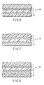
- FIG. 3 is a sectional view showing the third example of the structure of the laminated material of the present invention.
- FIG. 4 is a sectional view showing the fourth example of the structure of the laminated material of the present invention.
- FIG. 5 is a sectional view showing the fifth example of the structure of the laminated material of the present invention.
- FIG. 6 is a sectional view showing the sixth example of the structure of the laminated material of the present invention.
- FIG. 7 is a sectional view showing the seventh example of the structure of the laminated material of the present invention.
- FIG. 8 is a sectional view showing the eighth example of the structure of the laminated material of the present invention.
- FIG. 9 is a sectional view showing the ninth example of the structure of the laminated material of the present invention.
- FIG. 10 is a sectional view showing the 10th example of the structure of the laminated material of the present invention.
- FIG. 11 is a sectional view showing the 11th example of the structure of the laminated material of the present invention.
- a laminated material of the present invention comprises a substrate made of a plastic material, a first thin deposition layer formed on the substrate, a gas-barrier intermediate layer formed on the first thin deposition layer by coating with a coating agent containing at least a water-soluble polymer, and a second thin deposition layer formed on the intermediate layer.
- the present invention can provide a highly practical laminated material having superior gas barrier properties equivalent to those of metal foils, without using any metal foils.
- FIG. 1 is a sectional view showing the first example of the laminated material according to the present invention.
- This laminated material 10 has a structure in which a first thin deposition layer 2 , a gas-barrier intermediate layer 3 , and a second thin deposition layer 4 are laminated in this order on a plastic substrate 1 .
- Such excellent gas barrier properties cannot be achieved by any of a structure in which a single thin deposited film is formed on a substrate, a structure in which two such thin deposition layers are formed on a substrate, and a structure in which a gas-barrier resin layer similar to a gas-barrier intermediate layer is formed on these two thin deposition layers formed on a substrate.
- the present inventors conducted extensive research and have found that it is important to form a structure in which a gas-barrier intermediate layer 3 is sandwiched between first and second thin deposition layers 2 and 4 on a substrate 1 . This significantly lowers the oxygen permeability and the water vapor permeability. Consequently, a conventionally unobtainable, highly practical laminated material having gas barrier properties equivalent to those of metal foils is obtained.
- the gas barrier properties of the laminated material of the present invention can be represented by, e.g., the water vapor permeability and the oxygen permeability.
- the laminated material of the present invention preferably has a water vapor permeability of 0.2 (g/m 2 ⁇ day) or less, when, e.g., measurement is performed at a temperature of 40° C. and a humidity of 90% by using the Mokon method. Within this range, gas barrier properties equivalent to those of metal foils are obtained.
- the water vapor permeability is more preferably 0.01 (g/m 2 ⁇ day) to 0.1 (g/m 2 ⁇ day).
- the oxygen permeability is preferably 0.2 or less (cm 3 /m 2 ⁇ day ⁇ atm) at, e.g., a temperature of 30° C. and a humidity of 70%. Within this range, gas barrier properties equivalent to those of metal foils are obtained.
- the oxygen permeability is particularly preferably 0.01 to 0.1 (cm 3 /m 2 ⁇ day ⁇ atm).
- plastic substrate a single film and various laminated films can be used by taking into account the suitability as a packaging material or of a member of an electronic apparatus.
- main material of the plastic substrate it is possible to use, e.g., polyester films such as polyethyleneterephthalate (PET) and polyethylenenaphthalate (PEN), polyolefin films such as polyethylene and polypropyrene, a polystyrene film, a polyamide film, a polycarbonate film, a polyacrylonitrile film, and a polyimide film.
- a transparent film substrate is preferred.
- the plastic substrate can be either stretched or unstretched provided that it has mechanical strength and dimensional stability.
- the plastic material is usually processed into a film.
- a polyethyleneterephthalate film or polyamide film arbitrarily stretched in two axial directions is preferably used from the viewpoint of heat resistance.
- a pre-treatment on the surface of the plastic substrate examples are a corona treatment, low-temperature plasma treatment, ion bombarding treatment, chemical treatment, and solvent treatment.
- additives and stabilizers such as an antistatic agent, ultraviolet inhibitor, plasticizer, and lubricant can be used on the surface of this substrate away from the surface on which the thin deposition layers are formed.
- the practical thickness of the plastic substrate is preferably 3 to 200 ⁇ m, and more preferably, 6 to 30 ⁇ m.
- the first and second thin deposition layers are obtained by depositing a material having barrier properties against oxygen, water vapor, and the like.
- this material it is possible to use at least one type of material selected from metals such as aluminum, copper, and silver or metal oxides such as yttrium tantalum oxide, aluminum oxide, silicon oxide, and magnesium oxide.
- the first and second thin deposition layers can be made of the same material or different materials.
- FIGS. 2 and 3 are sectional views showing the second and third examples of the structure of the laminated material according to the present invention.
- a transparent laminated material 20 has a structure in which a first thin transparent deposition layer 6 substantially made of an inorganic oxide, a transparent gas-barrier intermediate layer 7 , and a second thin transparent deposition layer 8 substantially made of an inorganic oxide are laminated in this order on a transparent substrate 5 .
- At least one type of inorganic oxide selected from yttrium tantalum oxide, aluminum oxide, silicon oxide, and magnesium oxide can be used in the first and second thin deposition layers.
- a metal can be used in at least one of the first and second thin deposition layers.
- a laminated material 30 having shielding properties has a structure in which a first thin deposition layer 10 substantially made of a metal, a gas-barrier intermediate layer 11 , and a second thin deposition layer 12 substantially made of a metal are laminated in this order on a substrate 9 .
- the metal it is possible to use at least one type of a metal selected from aluminum, copper, and silver.
- aluminum, aluminum oxide, silicon oxide, and magnesium oxide are preferably used in at least one of the first and second thin deposition layers.
- the thickness of the first and second thin deposition layers is preferably 5 to 300 nm, although it depends upon the types of metal and oxide used and upon the composition of the thin deposition layers. If the film thickness of the thin deposition layers is less than 5 nm, no uniform films can be obtained, resulting in unsatisfactory gas barrier properties. If the film thickness exceeds 300 nm, no satisfactory flexibility can be held, so cracks are often formed by external factors such as bending and pulling. The thickness of the first and second thin deposition layers is more preferably 10 to 150 nm.
- the thickness of the first thin deposition layer is 10 to 40 nm
- the thickness of the second thin deposition layer is 10 to 40 nm.
- translucency can be obtained if the thickness of the metal is 5 to 30 nm, although this depends upon the type of the metal. High translucency can be obtained when the thickness of the metal is 5 to 15 nm.
- a 5- to 30-nm thick aluminum layer is formed as at least one of the first and second thin deposition layers, not only translucency but also electromagnetic wave shielding properties, an antistat effect, and gas barrier properties can be obtained.
- the thickness of this aluminum layer is more preferably 5 to 15 nm, since the translucency further increases.
- FIG. 4 is a sectional view showing the fourth example of the structure of the laminated material according to the present invention.
- this laminated material 40 has the same structure as in FIG. 2 except that a translucent second thin deposition layer having a film thickness of 5 to 30 nm and substantially made of a metal such as aluminum is formed as the second deposition layer instead of the second thin transparent deposition layer 8 .
- this thin translucent aluminum deposition layer can be formed as at least one of the first and second thin deposition layers.
- a conventional vacuum deposition method can be used as a method of forming this thin deposition layer. It is also possible to use, e.g., sputtering, ion plating, or plasma chemical vapor deposition (plasma CVD). When the productivity is taken into consideration, the vacuum deposition method is preferred. As a heating means of this vacuum deposition method, one of electron beam heating, resistance heating, and induction heating is preferred.
- deposition can be performed by using a plasma assisting method or an ion beam assisting method.
- reactive deposition by which oxygen gas or the like is blown during deposition can be performed.
- the gas-barrier intermediate layer sandwiched between the first and second thin deposition layers is formed by coating with a coating agent containing at least a water-soluble polymer component.
- water-soluble polymer examples include polyvinyl alcohol, polyvinyl pyrrolidone, starch, methyl cellulose, carboxymethyl cellulose, and sodium alginate.
- Polyvinyl alcohol (to be abbreviated as PVA hereinafter) is particularly preferred because the gas barrier properties improve.
- PVA herein mentioned is generally obtained by saponifying polyvinyl acetate.
- PVA is not particularly limited and includes so-called partially saponified PVA in which several tens of % of an acetic acid group remain and complete PVA in which only a few % of an acetic acid remain.
- the gas-barrier intermediate layer can be formed by coating the first thin deposition layer with a coating agent containing a water-soluble polymer component, and heating and drying this coating agent.
- the coating agent contains primarily at least one of i) one or more types of metal alkoxides and their hydrolyzed products and ii) tin chloride, and water or a water-alcohol solution mixture. That is, a solution in which a water-soluble polymer or tin chloride is dissolved in water or in a water-alcohol solution mixture, or a solution in which a water-soluble polymer and a metal alkoxide are dissolved, either directly or pre-hydrolyzed, in water or in a water-alcohol solution mixture, can be prepared as the coating agent.
- Tin chloride preferably used in the coating agent is stannous chloride (SnCl 2 ), stannic chloride (SnCl 4 ), or a mixture thereof.
- anhydrides and hydrates of these tin chlorides are suitably usable.
- the metal alkoxide is a compound represented by the formula M(OR) n wherein M is one member selected from metals such as Si, Ti, Al, and Zr, and R is one member selected from alkyl groups such as CH 3 and —C 2 H 5 .
- M is one member selected from metals such as Si, Ti, Al, and Zr
- R is one member selected from alkyl groups such as CH 3 and —C 2 H 5 .
- Practical examples are tetraethoxysilane Si(OC 3 H 6 ) 4 and triisopropoxy aluminum Al(O-2′-C 3 H 7 ) 3 . Of these compounds, tetraethoxysilane and triisopropoxy aluminum are preferred because they are relatively stable in an aqueous solvent after being hydrolyzed.
- An isocyanate compound to be added to the coating agent preferably has two or more isocyanate groups contained in each molecule.
- this isocyanate compound are monomers such as tolyleneisocyanate, triphenylmethanetriisocyanate, and trimethylxylenediisocyanate, and polymers and derivatives of these monomers.
- the coating agent As a method of coating the coating agent, it is possible to use a conventionally known coating means such as dipping, roll coating, screen printing, spraying, and gravure printing.
- the dried thickness of the gas-barrier intermediate layer is preferably 200 to 600 nm.
- the ratio of the thickness of the thin deposition layers (layers A and C) to the thickness of the gas-barrier intermediate layer is preferably 0.005 to 0.25.
- this thickness ratio of the thin deposition layers is lower than 0.005 or the dried thickness of the gas-barrier intermediate layer is less than 200 nm, no uniform coating film is obtained, and the gas barrier properties are often unsatisfactory. If the thickness ratio exceeds 0.25 or the dried thickness exceeds 600 nm, cracks are often produced because the flexibility is unsatisfactory.
- a primer layer can also be formed between the plastic substrate and the first thin deposition layer.
- FIG. 5 is a sectional view showing the fifth example of the structure of the laminated material according to the present invention.
- this laminated material 50 has the same structure as in FIG. 1 except that a primer layer 14 is formed between a substrate 1 and a first thin deposition layer 2 .
- the adhesion between the substrate 1 and the first thin deposition layer 2 can be increased. This can prevent peeling of the thin deposition layer after boiling sterilization or retort sterilization.
- a material suitable as the primer layer is a composition comprising of, e.g., polyesterpolyol or acrylpolyol, an isocyanate compound, and a silane coupling agent.
- Acrylpolyol used in the present invention is a polymeric compound which is obtained by polymerizing an acrylic acid derivative monomer or by copolymerizing an acrylic acid derivative monomer and another monomer, and which has a hydroxyl group at the end. This acrylpolyol is allowed to react with an isocyanate group of an isocyanate compound to be added later. It is particularly preferable to use acrylpolyol obtained by singly polymerizing an acrylic acid derivative monomer such as ethylmethacrylate, hydroxyethylmethacrylate, hydroxypropylmethacrylate, or hydroxybutylmethacrylate, or by copolymerizing any of these monomers and another monomer such as styrene. When the reactivity to an isocyanate compound is taken into consideration, the hydroxyl value is preferably 5 to 200 (KOH mg/g).
- Polyesterpolyol preferably used in the present invention is a polyester-based resin which is obtained from an acid material and an alcohol material by a known manufacturing method, and which has two or more hydroxyl groups at the end to be react with isocyanate groups of isocyanate compounds which are added late.
- the acid material are terephthalic acid, isophthalic acid, phthalic acid, methylphthalic acid, trimellitic acid, pyromellitic acid, adipic acid, sebacic acid, succinic acid, maleic acid, fumaric acid, tetrahydrophthalic acid, methyltetrahydrophthalic acid, hexahydrophthalic acid, and reactive derivatives of these acids.
- Examples of the alcohol material are ethyleneglycol, propyleneglycol, 1,3-butanediol, 1,4-hexanediol, diethyleneglycol, dipropyleneglycol, 1,4-cyclohexanedimethanol, neopentylglycol, bishydroxyethylterephthalate, trimethylolmethane, trimethylolpropane, glycerin, and pentaerythritol.
- This polyesterpolyol is allowed to react with an isocyanate group of an isocyanate compound to be added later.
- the isocyanate compound used in the present invention is added to increase the adhesion between the substrate and the thin deposition layer by urethane bonds formed when this isocyanate compound reacts with polyesterpolyol or acrylpolyol.
- the isocyanate compound functions primarily as a crosslinking agent or hardener.
- isocyanate compound it is possible to use monomers such as tolylenediisocyanate (TDI) and diphenylmethanediisocyanate (MDI) as aromatic compounds, xylenediisocyanate (XDI), hexalenediisocyanate (HMDI) and isophoronediisocyanate (IPDI) as aliphatic compounds, and polymers and derivatives of these monomers.
- TDI tolylenediisocyanate
- MDI diphenylmethanediisocyanate
- XDI xylenediisocyanate
- HMDI hexalenediisocyanate
- IPDI isophoronediisocyanate
- the blending ratio of polyesterpolyol or acrylpolyol to the isocyanate compound is not particularly restricted. However, if the amount of isocyanate compound is too small, poor hardening sometimes occurs; if the amount of isocyanate compound is too large, blocking or the like takes place, resulting in processing problems. Therefore, the blending ratio of polyesterpolyol or acrylpolyol to the isocyanate compound is preferably such that an isocyanate group derived from the isocyanate compound is 50 times a hydroxyl group derived from polyesterpolyol or acrylpolyol or less. It is particularly preferable that equal amounts of an isocyanate group and a hydroxyl group be blended.
- the mixing method is not particularly limited, so any known method can be used.
- any silane coupling agent containing an arbitrary organic functional group can be used.
- silane coupling agents such as ethyltrimethoxysilane, vinyltrimethoxysilane, ⁇ -chloropropylmethyldimethoxysilane, ⁇ -chloropropyltrimethoxysilane, glycidoxypropyltrimethoxysilane, ⁇ -methacryloxypropyltrimethoxysilane, and ⁇ -methacryloxypropylmethyldimethoxysilane, and hydrolyzed products of these silane coupling agents.
- silane coupling agents a silane coupling agent having a functional group which reacts with at least one of a hydroxyl group of acrylpolyol, a hydroxyl group of polyesterpolyol, and an isocyanate group of an isocyanate compound is particularly preferable.
- silane coupling agent examples include those containing an isocyanate group, such as ⁇ -isocyanatepropyltriethoxysilane and ⁇ -isocyanatepropyltrimethoxysilane, those containing an amino group, such as ⁇ -aminopropyltriethoxysilane, ⁇ -aminopropyltrimethoxysilane, N- ⁇ -(aminoethyl)- ⁇ -aminopropyltriethoxysilane, and ⁇ -phenylaminopropyltrimethoxysilane, and those containing an epoxy group, such as ⁇ -glycidoxypropyltrimethoxysilane and ⁇ -(3,4-epoxycyclohexyl)ethyltrimethoxysilane.
- an isocyanate group such as ⁇ -isocyanatepropyltriethoxysilane and ⁇ -isocyanatepropyltrimethoxysilane
- amino group
- silane coupling agents can be used singly or in the form of a mixture of two types thereof.
- An organic functional group present at one end of any of these silane coupling agents interacts in a composite material consisting of polyesterpolyol or acrylpolyol and an isocyanate compound.
- a covalent bond is formed using a silane coupling agent containing a functional group which reacts with at least one of a hydroxyl group of polyesterpolyol, a hydroxyl group of acrylpolyol, and an isocyanate group of an isocyanate compound. In this manner, a stronger primer layer can be formed.
- the blending ratio of polyesterpolyol or acrylpolyol to the silane coupling agent is preferably 1/1 to 100/1, and more preferably, 2/1 to 50/1, as a weight ratio.
- Dissolving and diluting solvents are not particularly limited provided that dissolution and dilution are possible.
- examples are esters such as ethyl acetate and butyl acetate, alcohols such as methanol, ethanol, and isopropyl alcohol, ketones such as methylethylketone, and aromatic hydrocarbons such as toluene and xylene.
- These solvents can be used singly or arbitrarily blended.
- an aqueous solution of, e.g., hydrochloric acid or acetic acid is sometimes used to hydrolyze the silane coupling agent. Therefore, it is more preferable to use, as a co-solvent, a solvent in which isopropyl alcohol or the like and ethyl acetate as a polar solvent are arbitrarily mixed.
- a reaction catalyst can be added to promote the reaction when the silane coupling agent is blended.
- tin compounds such as tin chloride (SnCl 2 , SnCl 4 ), tin oxychloride (SnOHCl, Sn(OH) 2 Cl 2 ), and tin alkoxide are preferred in respect of reactivity and polymerization stability.
- These catalysts can be added directly during blending or after being dissolved in a solvent such as methanol. Assuming that the molar ratio of this catalyst is 1, the molar ratio of the silane coupling agent is preferably 10 to 10,000, and more preferably, 100 to 2,000.
- a primer solution for forming the primer layer is prepared by making a composite solution by mixing polyesterpolyol or acrylpolyol, the isocyanate compound, and the silane coupling agent at a given blending ratio, and coating a substrate with this composite solution.
- the composition solution is made as follows. That is, the silane coupling agent and polyesterpolyol or acrylpolyol can be mixed, and a solvent and diluting agent can be added to dilute the mixture to an arbitrary concentration. After that, the isocyanate compound can be mixed to make a composite solution.
- the silane coupling agent can be mixed in a solvent beforehand and polyesterpolyol or acrylpolyol can be mixed after that. A solvent and diluting agent can be added to dilute the mixture to a given concentration. After that, the isocyanate compound can be added to make a composite solution.
- additives can also be added to this primer solution if necessary.
- examples are tertiary amine, an imidazole derivative, a metal chloride of carboxylic acid, hardening accelerators such as quaternary ammonium salt and quaternary phosphonium salt, oxidation inhibitors such as phenol-based, sulfur-based, and phosphite-based oxidation inhibitors, a leveling agent, a flow modifier, a catalyst, a crosslinking accelerator, and a filler.
- the dried thickness of the primer layer is preferably 10 to 2,000 nm. If the thickness is less than 10 nm, a uniform coating film is difficult to obtain, and this may lower the adhesion. If the thickness exceeds 2,000 nm, the coating film cannot maintain its flexibility and often cracks owing to external factors.
- the thickness of the primer layer is particularly preferably 50 to 500 nm.
- the primer layer As a method of forming the primer layer, it is possible to use known printing methods such as offset printing, gravure printing, and silk screen printing, and known coating methods such as roll coating, knife edge coating, and gravure coating.
- the drying conditions can be generally used conditions.
- a gas-barrier intermediate layer can also be formed on the second thin deposition layer.
- FIG. 6 is a sectional view showing the sixth example of the structure of the laminated material according to the present invention.
- this laminated material 60 has the same structure as in FIG. 1 except that a gas-barrier resin layer 15 is additionally formed on a second thin deposition layer 4 .
- the gas barrier properties of the laminated material further improve, and the post-processing resistance also further improves.
- This gas-barrier resin layer is similar to the above-mentioned, gas-barrier intermediate layer and can be formed by a method similar to the formation method of this gas-barrier intermediate layer.
- the gas-barrier resin layer and the gas-barrier intermediate layer can be made of the same material or different materials.
- a printing layer can also be formed on the second deposition layer or on the gas-barrier resin layer.
- FIG. 7 is a sectional view showing the seventh example of the structure of the laminated material according to the present invention.
- this laminated material 70 has the same structure as in FIG. 1 except that a printing layer 16 is formed on a second thin vapor deposition layer 4 .
- This printing layer 16 is formed to practically use the laminated material as a packaging bag. With this printing layer 16 , images such as characters and patterns can be formed as needed.
- the printing layer is made of ink formed by adding additives to a conventionally used ink binder resin.
- the ink binder resin are urethane-based, acryl-based, nitrocellulose-based, and rubber-based resins.
- the additives are various pigments, extender pigments, plasticizers, drying agents, and stabilizers.
- the dried film thickness of the printing layer is preferably 100 to 2,000 nm as a solid component.
- a heat-sealing layer can be formed, via any intervening film, on the second thin deposition layer, gas-barrier resin layer, or printing layer.
- FIG. 8 is a sectional view showing the eighth example of the structure of the laminated material according to the present invention.
- this laminated material 80 has the same structure as in FIG. 1 except that a heat-sealing layer 18 is formed on a second thin deposition layer 4 via an intervening film 17 .
- the intermediate film 17 is formed below the heat-sealing layer 18 .
- this intervening film 17 is formed between the heat-sealing layer and the gas-barrier resin layer or the printing layer other than the second thin deposition layer 4 .
- the intervening film 17 can increase the breaking strength and piercing strength of a packaging bag.
- this intervening film is preferably one member selected from a biaxially oriented nylon film, biaxially oriented polyethyleneterephthalate film, and biaxially oriented polypropylene film.
- the thickness is determined in accordance with the material and the required quality. However, the thickness is preferably 10 to 30 ⁇ m in practice.
- the film can be laminated by any known method such as a dry laminating method by which the film is bonded using an adhesive such as a two-part hardening type urethane-based resin.
- the heat-sealing layer 18 is formed as an adhesive layer when the laminated material is molded into a packaging bag.
- this heat-sealing layer examples include resins such as polyethylene, polypropylene, an ethylene-vinyl acetate copolymer, an ethylene-methacrylic acid copolymer, an ethylene-methacrylic ester copolymer, an ethylene-acrylic acid copolymer, an ethylene-acrylic ester copolymer, and metal crosslinked products of these materials.
- resins such as polyethylene, polypropylene, an ethylene-vinyl acetate copolymer, an ethylene-methacrylic acid copolymer, an ethylene-methacrylic ester copolymer, an ethylene-acrylic acid copolymer, an ethylene-acrylic ester copolymer, and metal crosslinked products of these materials.
- the thickness of the heat-sealing layer can be determined in accordance with the purpose, it is preferably 15 to 200 ⁇ m in practice.
- An example of the method of forming the heat-sealing layer is dry lamination by which a film made of the aforementioned resin is bonded using an adhesive such as a two-part hardening type urethane resin.
- the formation method is not limited to this method, so the heat-sealing layer can be laminated by some other known method.
- a third thin deposition layer different from the second thin deposition layer can be laminated on this second thin deposition layer.
- FIG. 9 is a sectional view showing the ninth embodiment of the structure of the laminated material according to the present invention.
- a laminated material 90 according to the ninth example has the same structure as in FIG. 1 except that a third thin deposition layer 19 different from a second thin deposition layer 4 is formed on this second thin deposition layer 4 .
- this third thin deposition layer 19 a layer similar to the first and second thin deposition layers can be used.
- an inorganic oxide as the first and second thin deposition layers 2 and 4 , and a metal such as aluminum as the third thin deposition layer 19 .
- a metal is used as the thin deposition layer, an antistat effect resulting from the conductivity of the metal can be expected.
- aluminum is used as this metal, electromagnetic wave shielding properties can be obtained.
- the oxygen permeability and water vapor permeability further improve when at least one of aluminum oxide, silicon oxide, and magnesium oxide is used as the inorganic oxide and aluminum is used as the metal.
- translucency is obtained by setting the thickness of aluminum to, e.g., 5 to 30 nm.
- the first to ninth embodiments described above exhibit the structure basically having two thin deposition layers and one gas-barrier intermediate layer formed between these two thin deposition layers, and the applications of this structure.
- the present invention is not limited to this structure. That is, the present invention also includes a multilayered structure having three or more thin deposition layers and gas-barrier intermediate layers each formed between these thin deposition layers.
- the thin deposition layers can be the same or different.
- the gas-barrier intermediate layers can also be the same or different.
- FIG. 10 is a sectional view showing the 10th example of the structure of the laminated material according to the present invention.
- this laminated material 100 has a multilayered structure in which gas-barrier intermediate layers 3 and 20 are formed between first to third thin deposition layers 2 , 4 , and 19 .
- This multilayered structure is the same as in FIG. 1 except that the third thin deposition layer 19 is formed on the second thin deposition layer 4 via the gas-barrier intermediate layer 20 .
- the third thin deposition layer 19 a layer similar to the first and second thin deposition layers can be used.
- a gas-barrier intermediate layer 20 can be formed between the second thin deposition layer 19 which is, e.g., an inorganic oxide layer and the third thin deposition layer which is a metal layer such as an aluminum layer. In this manner, an example of the laminated material having this multilayered structure is obtained.
- PET biaxially oriented polyethyleneterephthalate
- the first and second solutions were mixed at a weight ratio of 60 to 40 to obtain the intermediate layer coating solution 1.
- a layer of the obtained intermediate layer coating solution 1 was formed by gravure coating and dried at 120° C. for 1 min to form a 500-nm thick gas-barrier intermediate layer.
- the substrate on which the first thin deposition layer and the gas-barrier intermediate layer were formed was placed in the electron beam heating type vacuum deposition apparatus.
- Metal aluminum was evaporated, and oxygen gas was introduced to the evaporated aluminum to deposit a 15-nm thick aluminum oxide layer as a second thin deposition layer, thereby obtaining a transparent laminated material.
- the structure of the obtained laminated material was the same as in FIG. 2 .
- the obtained laminated material was tested for gas barrier properties, transparency, and environmental compatibility.
- the water vapor permeability (g/m 2 ⁇ day) was measured. This water vapor permeability was measured using the Mokon method, and the measurement conditions were 40° C.–90% RH.
- the environmental compatibility was checked by performing an incineration test and checking whether chlorine gas was produced or not and any residue remained. ⁇ indicates high compatibility, and X indicates unsatisfactory compatibility.
- the laminated material was totally evaluated for the transparency, the water vapor permeability indicating the gas barrier properties, and the environmental compatibility.
- Table 1 also shows the thickness ratio of the first thin deposition layer, gas-barrier intermediate layer, and second thin deposition layer.
- a transparent laminated material was obtained following the same procedures as in Example 1 except that instead of aluminum oxide, a silicon oxide layer having a thickness of about 30 nm was vacuum-deposited as a second thin deposition layer by a resistance heating type vacuum deposition method.
- a transparent laminated material was obtained following the same procedures as in Example 1 except that instead of aluminum oxide, a silicon oxide layer having a thickness of about 20 nm was deposited as a first thin deposition layer by a resistance heating type vacuum deposition method.
- a transparent laminated material was obtained following the same procedures as in Example 1 except that a magnesium oxide layer having a thickness of about 15 nm was deposited as a first thin deposition layer by an electron beam heating type vacuum deposition method.
- a transparent laminated material was obtained following the same procedures as in Example 1 except that no second thin deposition layer was formed.
- a transparent laminated material was obtained following the same procedures as in Example 1 except that a gas-barrier intermediate layer was formed after a second thin deposition layer was deposited on a first thin deposition layer.
- the laminated materials of Examples 1 to 4 satisfied all of the transparency with which the contents could be visually seen, the high-level gas barrier properties equivalent to those of metal foils, with which gases and the like having influence on the contents could be stopped, and the environmental compatibility.
- a 12- ⁇ m thick biaxially oriented PET film was prepared.
- a primer layer coating solution was prepared as follows.
- Ethyl acetate was prepared as a diluting solvent. 10 parts by weight of acrylpolyol were mixed in 1 part by weight of ⁇ -isocyanatepropyltrimethylsilane, and the mixture was stirred.
- the obtained solution mixture was diluted with ethyl acetate so that the solid component was 2 wt %, thereby preparing a primer layer coating solution.
- One surface of the PET film was coated with this primer layer coating solution by gravure coating, and the solution was dried to form a 0.1- ⁇ m thick primer layer.
- Example 1 After that, a layer of the same intermediate layer coating agent 1 as used in Example 1 was formed by gravure coating and dried at 120° C. for 1 min, thereby forming a 400-nm thick gas-barrier intermediate layer.
- a 15- ⁇ m thick biaxially oriented nylon film as an intervening film was laminated on the obtained gas-barrier resin layer by dry lamination by using a two-part hardening type urethane-based adhesive.
- a 70- ⁇ m thick unstretched polypropyrene film as a heat-sealing layer was laminated by dry lamination by using the two-part hardening type urethane-based adhesive, thereby manufacturing a packaging material.
- FIG. 11 is a sectional view showing the structure of this packaging material.
- this packaging material 110 has a structure in which a primer layer 14 , a first thin deposition layer 2 , a gas-barrier intermediate layer 3 , a second thin deposition layer 4 , a gas-barrier resin layer 15 , an intervening film 17 , and a heat-sealing layer 18 were laminated in this order on a substrate 1 .
- a pouch having sealing portions on its four sides was made by using the obtained packaging material, and filled with 150 g of water as a content.
- Retort sterilization was performed at 121° C. for 30 min. Test for gas barrier properties before and after retort sterilization
- the oxygen permeability (cm 3 /m 2 ⁇ day ⁇ atm) of the packaging material before retort sterilization and that of the packaging material after retort sterilization were measured under measurement conditions of 30° C.–70% RH.
- the lamination strength (N/15 mm) of the packaging material before retort sterilization and that of the packaging material after retort sterilization were measured at a peeling rate of 300 mm/min by the ISO 4578 (JIS K 6854) test.
- a transparent laminated material was obtained following the same procedures as in Example 5 except that instead of the second thin deposition layer, silicon oxide having a thickness of about 25 nm was deposited by a resistance heating type vacuum deposition method.
- a transparent laminated material was obtained following the same procedures as in Example 5 except that no gas-barrier intermediate layer was formed.
- a transparent laminated material was obtained following the same procedures as in Example 5 except that no primer layer was formed.
- a laminated material was obtained following the same procedures as in Example 1 except that the thickness of a gas-barrier intermediate layer was 400 nm.
- the water vapor permeability of the obtained laminated material was measured.
- ⁇ indicates a water vapor permeability of 0.2 or less, and X indicates other values.
- Table 3 also shows the thickness ratio of the first thin deposition layer, gas-barrier intermediate layer, and second thin film deposition layer.
- a laminated material was obtained following the same procedures as in Example 8 except that silicon oxide having a thickness of about 35 nm was deposited as a second thin deposition layer by using a resistance heating type vacuum deposition apparatus.
- a laminated material was obtained following the same procedures as in Example 8 except that metal aluminum was evaporated to deposit 40-nm thick aluminum as a second thin deposition layer by using an electron beam heating type vacuum deposition apparatus.
- the surface resistance value of this laminated material was 45 ⁇ /cm 2 .
- a laminated material was obtained following the same procedures as in Example 8 except that a primer layer similar to that in Example 5 was formed.
- the obtained laminated material was used to make a packaging material and conduct retort tests following the same procedures as in Example 5. The results are shown in Table 4 to be presented later.
- a laminated material was obtained following the same procedures as in Example 11 except that a 15- ⁇ m thick biaxially oriented nylon film (ONY) was used as a substrate.
- ONY biaxially oriented nylon film
- a 60- ⁇ m thick low-density polyethylene film was laminated as a heat-sealing layer by dry lamination by using a two-part hardening type urethane-based adhesive, thereby making a packaging material.
- the obtained packaging material was used to conduct the following boiling test.
- a pouch having sealing portions on its four sides was made by using the obtained packaging material, and filled with 150 g of water as a content.
- a laminated material was obtained following the same procedures as in Example 11 except that a 0.5- ⁇ m thick gas-barrier resin layer was formed on a second thin deposition layer by using the same coating agent as a gas-barrier intermediate layer.
- the obtained laminated material was used to make a packaging material and conduct retort tests following the same procedures as in Example 5. The results are shown in Table 4.
- a laminated material was obtained following the same procedures as in Example 10 except that 10-nm thick metal aluminum was deposited as a second thin deposition layer.
- the surface resistance value of this laminated material was 50 ⁇ /cm 2 .
- the light transmittance at a wavelength of 500 nm was 40%.
- a laminated material was obtained following the same procedures as in Example 8 except that no second thin deposition layer was formed.
- a laminated material was obtained following the same procedures as in Example 11 except that no second thin deposition layer was formed.
- the obtained laminated material was used to make a packaging material and conduct retort tests following the same procedures as in Example 5. The results are shown in Table 4.
- a laminated material was obtained following the same procedures as in Example 12 except that no second thin deposition layer was formed.
- a laminated material was obtained following the same procedures as in Example 11 except that the thickness of a gas-barrier intermediate layer was 50 nm.
- a laminated material was obtained following the same procedures as in Example 8 except that the thickness of each of first and second thin deposition layers was 20 nm, and that the second thin deposition layer was deposited directly on the first thin deposition layer without forming any gas-barrier intermediate layer.
- a laminated material was obtained following the same procedures as in Comparative Example 7 except that a silicon oxide layer having a thickness of about 40 nm was deposited as a second thin deposition layer by using a resistance heating type vacuum deposition apparatus.
- a laminated material was obtained following the same procedures as in Comparative Example 7 except that a gas-barrier resin layer was formed on a second thin deposition layer in the same manner as for the gas-barrier intermediate layer in Example 8.
- a laminated material was obtained by depositing 10-nm thick metal aluminum in the same manner as in Example 14 on a second thin deposition layer of a laminated material obtained following the same procedures as in Example 8.
- the surface resistance value of this laminated material was 50 ⁇ /cm 2 .
- the light transmittance at a wavelength of 500 nm was 40%.
- Example 15 high-level gas barrier properties equivalent to those of metal foils were obtained in Examples 8 to 14 and 16.
- Example 15 the ratio of the gas-barrier intermediate layer to the first and second thin deposition layers was large, so the oxygen permeability was slightly higher than those of Examples 8 to 13.
- Table 4 above shows that Examples 11 and 13 had high-level gas barrier properties and lamination strength equivalent to those of metal foils even when retort sterilization was performed.
- Example 12 had satisfactory gas barrier properties and lamination strength both before and after the boiling test. However, when a single thin deposition layer was formed without forming any second thin deposition layer as in Comparative Example 6, particularly the oxygen permeability rose to deteriorate the gas barrier properties.
- a laminated material of the present invention realizes superior gas barrier properties equivalent to those of metal foils without using any metal foils, and maintains the gas barrier properties and lamination strength even after boiling sterilization or retort sterilization. Therefore, this laminated material can be widely used in the fields of packaging and electronic apparatus members.
Landscapes
- Chemical & Material Sciences (AREA)
- Organic Chemistry (AREA)
- Chemical Kinetics & Catalysis (AREA)
- Health & Medical Sciences (AREA)
- Medicinal Chemistry (AREA)
- Polymers & Plastics (AREA)
- Engineering & Computer Science (AREA)
- Inorganic Chemistry (AREA)
- Life Sciences & Earth Sciences (AREA)
- Wood Science & Technology (AREA)
- General Chemical & Material Sciences (AREA)
- Materials Engineering (AREA)
- Mechanical Engineering (AREA)
- Metallurgy (AREA)
- Ceramic Engineering (AREA)
- Laminated Bodies (AREA)
- Physical Vapour Deposition (AREA)
- Photoreceptors In Electrophotography (AREA)
- Wrappers (AREA)
Applications Claiming Priority (3)
| Application Number | Priority Date | Filing Date | Title |
|---|---|---|---|
| JP2001-109502 | 2001-04-09 | ||
| JP2001109502 | 2001-04-09 | ||
| PCT/JP2002/003339 WO2002083408A1 (fr) | 2001-04-09 | 2002-04-03 | Corps stratifie |
Publications (2)
| Publication Number | Publication Date |
|---|---|
| US20040115445A1 US20040115445A1 (en) | 2004-06-17 |
| US7288313B2 true US7288313B2 (en) | 2007-10-30 |
Family
ID=18961426
Family Applications (1)
| Application Number | Title | Priority Date | Filing Date |
|---|---|---|---|
| US10/473,950 Expired - Lifetime US7288313B2 (en) | 2001-04-09 | 2002-04-03 | Laminated body |
Country Status (12)
| Country | Link |
|---|---|
| US (1) | US7288313B2 (zh) |
| EP (1) | EP1384571B1 (zh) |
| JP (2) | JP4085814B2 (zh) |
| KR (1) | KR100831277B1 (zh) |
| CN (1) | CN100448661C (zh) |
| AT (1) | ATE416914T1 (zh) |
| CA (1) | CA2443114C (zh) |
| DE (1) | DE60230255D1 (zh) |
| MX (1) | MXPA03009151A (zh) |
| TW (1) | TW592977B (zh) |
| WO (1) | WO2002083408A1 (zh) |
| ZA (1) | ZA200307664B (zh) |
Cited By (5)
| Publication number | Priority date | Publication date | Assignee | Title |
|---|---|---|---|---|
| US20100112255A1 (en) * | 2007-04-04 | 2010-05-06 | Tetra Laval Holdings & Finances S.A. | Packaging laminate, method for manufacturing of the packaging laminate and packaging container produced there from |
| US20110097020A1 (en) * | 2009-10-23 | 2011-04-28 | H.J. Heinz Company | Condiment package and packaging material having extended shelf-life |
| US20120231269A1 (en) * | 2009-11-18 | 2012-09-13 | Nitto Denko Corporation | Composite film |
| US20130280537A1 (en) * | 2010-12-28 | 2013-10-24 | Toyo Seikan Group Holdings, Ltd. | Two-part curable Oxygen-absorbable Resin Composition, and Oxygen-absorbable Adhesive Agent |
| US11118080B2 (en) | 2016-08-12 | 2021-09-14 | Sun Chemical Corporation | Reinforcement barrier coatings |
Families Citing this family (52)
| Publication number | Priority date | Publication date | Assignee | Title |
|---|---|---|---|---|
| JP4552392B2 (ja) * | 2003-06-24 | 2010-09-29 | 凸版印刷株式会社 | 水分吸収機能を持つ蒸着フィルム積層体 |
| JP2005074731A (ja) * | 2003-08-29 | 2005-03-24 | Toppan Printing Co Ltd | 高ガスバリア性を有する透明積層体 |
| JP4629362B2 (ja) * | 2004-05-12 | 2011-02-09 | 大日本印刷株式会社 | バリア性フィルムおよびそれを使用した積層材 |
| US7811669B2 (en) * | 2004-08-17 | 2010-10-12 | Dai Nippon Printing Co., Ltd. | Gas barrier laminated film and process for producing the same |
| JP2006056007A (ja) * | 2004-08-17 | 2006-03-02 | Dainippon Printing Co Ltd | ガスバリア性積層フィルムおよびそれを使用した積層材 |
| ES2307110T3 (es) * | 2005-03-24 | 2008-11-16 | SCHREINER GROUP GMBH & CO. KG | Elemento electroluminiscente. |
| JP2006289884A (ja) * | 2005-04-14 | 2006-10-26 | Dainippon Printing Co Ltd | ガスバリア性積層体 |
| CA2603813A1 (en) * | 2005-04-18 | 2006-10-26 | Advanced Plastics Technologies Luxembourg S.A. | Water-resistant coated articles and methods of making same |
| ITTO20050718A1 (it) | 2005-10-10 | 2007-04-11 | Consorzio Interuniverstario | Materiale laminato ad elevato effetto barriera all'ossigeno |
| JP2007301878A (ja) * | 2006-05-12 | 2007-11-22 | Toppan Printing Co Ltd | 透明蒸着フィルム及び包装材料 |
| JP5163488B2 (ja) * | 2006-09-08 | 2013-03-13 | 凸版印刷株式会社 | 積層体 |
| JP2008066629A (ja) * | 2006-09-11 | 2008-03-21 | Toppan Printing Co Ltd | 太陽電池用裏面保護シートおよび太陽電池モジュール |
| KR100877263B1 (ko) * | 2007-04-04 | 2009-01-09 | 엘에스엠트론 주식회사 | 연성 금속박막 적층필름 제조방법 |
| JP5493253B2 (ja) * | 2007-09-07 | 2014-05-14 | 凸版印刷株式会社 | ガスバリアフィルム |
| KR100921960B1 (ko) | 2007-11-28 | 2009-10-15 | 이상민 | 디스플레이용 플라스틱 기판 및 그 제조 방법 |
| JP2010030942A (ja) * | 2008-07-28 | 2010-02-12 | Mitsubishi Gas Chemical Co Inc | ピロメリット酸二無水物の保存方法 |
| US9983456B2 (en) * | 2008-08-19 | 2018-05-29 | Hitachi Chemical Company, Ltd. | Light control film |
| US10156767B2 (en) * | 2008-08-19 | 2018-12-18 | Hitachi Chemical Company, Ltd. | Light control film |
| JP2010076212A (ja) * | 2008-09-25 | 2010-04-08 | Toppan Printing Co Ltd | ガスバリア積層フィルム |
| JP5375014B2 (ja) * | 2008-10-09 | 2013-12-25 | 大日本印刷株式会社 | ガスバリア性積層フィルム |
| JP5436128B2 (ja) * | 2008-12-16 | 2014-03-05 | 株式会社クラレ | スパウト付きパウチ |
| EP2272928A1 (de) | 2009-06-23 | 2011-01-12 | Fraunhofer-Gesellschaft zur Förderung der angewandten Forschung e.V. | Hochbarrierenverbunde und Verfahren zu ihrer Herstellung |
| WO2010092954A1 (ja) | 2009-02-13 | 2010-08-19 | 日立化成工業株式会社 | 調光フィルム |
| EP2397894A4 (en) | 2009-02-13 | 2017-12-06 | Hitachi Chemical Company, Ltd. | Light modulation film |
| JP5381159B2 (ja) * | 2009-02-27 | 2014-01-08 | 大日本印刷株式会社 | ガスバリア性積層フィルム及びその製造方法 |
| CN102191462A (zh) * | 2010-03-15 | 2011-09-21 | 三菱综合材料株式会社 | 薄膜形成用气相沉积材、具备该薄膜的薄膜片材和层压片材 |
| JP4658226B1 (ja) * | 2010-03-23 | 2011-03-23 | 尾池工業株式会社 | ガスバリアフィルムの製造方法及びガスバリアフィルム |
| JP5334900B2 (ja) | 2010-03-25 | 2013-11-06 | 富士フイルム株式会社 | ガスバリアフィルムおよびデバイス |
| JP5626587B2 (ja) * | 2011-03-25 | 2014-11-19 | Dic株式会社 | ガスバリア性フィルム |
| WO2013018720A1 (ja) * | 2011-08-04 | 2013-02-07 | 三菱樹脂株式会社 | ガスバリア性積層体 |
| JP5934544B2 (ja) | 2012-03-29 | 2016-06-15 | 富士フイルム株式会社 | ガスバリアフィルム |
| JP2013233744A (ja) * | 2012-05-09 | 2013-11-21 | Mitsubishi Plastics Inc | ガスバリア性フィルム及びガスバリア性フィルムの製造方法 |
| JP6015134B2 (ja) * | 2012-05-30 | 2016-10-26 | 大日本印刷株式会社 | 包装材料 |
| EP2883248B1 (en) | 2012-08-08 | 2017-07-19 | 3M Innovative Properties Company | Photovoltaic devices with encapsulating barrier film |
| WO2014025384A1 (en) | 2012-08-08 | 2014-02-13 | 3M Innovative Properties Company | Urea (multi)-(meth)acrylate (multi)-silane compositions and articles including the same |
| JP6171419B2 (ja) * | 2013-03-08 | 2017-08-02 | 凸版印刷株式会社 | ガスバリア性フィルムの製造方法 |
| JP5870962B2 (ja) * | 2013-05-30 | 2016-03-01 | 大日本印刷株式会社 | ガスバリア性積層フィルム |
| JP5979319B2 (ja) * | 2013-09-13 | 2016-08-24 | 凸版印刷株式会社 | 波長変換シート及びバックライトユニット |
| KR102446693B1 (ko) * | 2014-04-04 | 2022-09-26 | 도판 인사츠 가부시키가이샤 | 파장 변환 시트, 백라이트 유닛 및 형광체용 보호 필름 |
| JP6102986B2 (ja) * | 2015-06-11 | 2017-03-29 | コニカミノルタ株式会社 | 水蒸気バリアーフィルムの製造方法、水蒸気バリアーフィルム、電子機器及び有機エレクトロルミネッセンスパネル |
| JP6578765B2 (ja) * | 2015-06-30 | 2019-09-25 | 凸版印刷株式会社 | ガスバリア性積層体およびその製造方法 |
| JP6202074B2 (ja) | 2015-11-20 | 2017-09-27 | 凸版印刷株式会社 | 波長変換シート |
| DK178929B9 (en) * | 2015-12-15 | 2017-06-26 | Radiometer Medical Aps | A Bag Containing a Reference Fluid |
| JP6215500B1 (ja) * | 2017-03-31 | 2017-10-18 | 株式会社松風 | 弱酸性化合物を含む歯科用プライマー |
| CN108130821A (zh) * | 2017-12-15 | 2018-06-08 | 常德金德新材料科技股份有限公司 | 高阻隔镭射纸及其制备方法 |
| KR20200135831A (ko) | 2018-03-23 | 2020-12-03 | 다이니폰 인사츠 가부시키가이샤 | 배리어 수지 필름, 배리어 적층체 및 상기 배리어 적층체를 이용한 포장 재료 |
| US11802188B2 (en) * | 2018-06-13 | 2023-10-31 | Michelman, Inc. | Acid-functional copolymer coatings for polymeric substrates |
| JP7331444B2 (ja) * | 2019-05-10 | 2023-08-23 | 大日本印刷株式会社 | バリアフィルム |
| KR102305248B1 (ko) * | 2020-02-12 | 2021-09-24 | 도레이첨단소재 주식회사 | 가스 배리어 알루미늄 증착필름 및 그의 제조방법 |
| KR102340402B1 (ko) * | 2021-05-28 | 2021-12-16 | 고려대학교 산학협력단 | 수용성 복사냉각 코팅층을 포함하는 복사 냉각 소자 |
| KR102370711B1 (ko) * | 2021-06-18 | 2022-03-07 | 고려대학교 산학협력단 | 불소수지 고분자 물질을 이용한 복사 냉각 소자 |
| TWI789930B (zh) * | 2021-10-01 | 2023-01-11 | 南亞塑膠工業股份有限公司 | 食品包裝用的阻隔膜及其製造方法 |
Citations (18)
| Publication number | Priority date | Publication date | Assignee | Title |
|---|---|---|---|---|
| US3442686A (en) | 1964-03-13 | 1969-05-06 | Du Pont | Low permeability transparent packaging films |
| JPS62156942A (ja) | 1985-12-28 | 1987-07-11 | 東洋紡績株式会社 | 複層ガスバリヤ−性フイルム又はシ−ト並びにその製造方法 |
| JPS6328017A (ja) | 1986-07-21 | 1988-02-05 | Mitsubishi Electric Corp | 非晶質金属鉄心の焼鈍方法 |
| US4937139A (en) | 1987-04-30 | 1990-06-26 | American National Can Company | Peelable packaging and sheet materials and compositions for use therein |
| US4950512A (en) | 1983-07-09 | 1990-08-21 | Fuji Photo Film Co., Ltd. | Laminated material and formed article for packaging photographic materials |
| JPH02258251A (ja) | 1988-12-05 | 1990-10-19 | Mitsubishi Monsanto Chem Co | 防湿フィルム |
| US5112673A (en) | 1988-12-05 | 1992-05-12 | Mitsubishi Kasei Polytec Company | Laminated moistureproof film with silicon oxide core layer |
| US5153074A (en) | 1991-11-05 | 1992-10-06 | Mobil Oil Corporation | Metallized film combination |
| JPH0565644A (ja) | 1991-03-12 | 1993-03-19 | Toppan Printing Co Ltd | 蒸着フイルムの製造方法 |
| JPH06234186A (ja) | 1993-02-10 | 1994-08-23 | Mitsui Toatsu Chem Inc | 高ガスバリヤー性透明電極フィルム |
| US5370937A (en) * | 1993-05-14 | 1994-12-06 | Dow Corning Corporation | Film for packaging having oxygen barrier characteristics |
| JPH08318591A (ja) | 1995-05-26 | 1996-12-03 | Toppan Printing Co Ltd | 蒸着層を有するバリア材料、およびこのバリア材料を用いた積層材料 |
| JPH10507705A (ja) | 1996-04-04 | 1998-07-28 | シグマ ラボラトリーズ オブ アリゾナ インコーポレーテッド | ハイブリッドポリマーフィルム |
| JPH11147276A (ja) | 1997-11-17 | 1999-06-02 | Toppan Printing Co Ltd | ガスバリア性透明積層体 |
| JP2000127300A (ja) | 1998-10-22 | 2000-05-09 | Toppan Printing Co Ltd | 強密着ガスバリア透明積層体 |
| JP2000185366A (ja) | 1998-12-24 | 2000-07-04 | Dainippon Printing Co Ltd | ガスバリア性フィルムとその製造方法およびガスバリア性フィルムを用いた積層材 |
| JP2000238172A (ja) | 1999-02-25 | 2000-09-05 | Toppan Printing Co Ltd | 蒸着フィルムおよびこの蒸着フィルムを用いた包装材料 |
| EP1132197A2 (de) | 2000-02-04 | 2001-09-12 | Wolff Walsrode AG | Längsgereckte im Vakuum bedampfte Verpackungsfolien |
Family Cites Families (2)
| Publication number | Priority date | Publication date | Assignee | Title |
|---|---|---|---|---|
| JPH0414440A (ja) * | 1990-05-07 | 1992-01-20 | Toray Ind Inc | 積層フィルム |
| DE4438359C2 (de) * | 1994-10-27 | 2001-10-04 | Schott Glas | Behälter aus Kunststoff mit einer Sperrbeschichtung |
-
2002
- 2002-04-03 CN CNB028080076A patent/CN100448661C/zh not_active Expired - Lifetime
- 2002-04-03 US US10/473,950 patent/US7288313B2/en not_active Expired - Lifetime
- 2002-04-03 CA CA002443114A patent/CA2443114C/en not_active Expired - Lifetime
- 2002-04-03 DE DE60230255T patent/DE60230255D1/de not_active Expired - Lifetime
- 2002-04-03 MX MXPA03009151A patent/MXPA03009151A/es active IP Right Grant
- 2002-04-03 JP JP2002581186A patent/JP4085814B2/ja not_active Expired - Fee Related
- 2002-04-03 WO PCT/JP2002/003339 patent/WO2002083408A1/ja active IP Right Grant
- 2002-04-03 AT AT02714430T patent/ATE416914T1/de not_active IP Right Cessation
- 2002-04-03 EP EP02714430A patent/EP1384571B1/en not_active Expired - Lifetime
- 2002-04-03 KR KR1020037013241A patent/KR100831277B1/ko active IP Right Grant
- 2002-04-08 TW TW091106980A patent/TW592977B/zh not_active IP Right Cessation
-
2003
- 2003-10-01 ZA ZA200307664A patent/ZA200307664B/xx unknown
-
2007
- 2007-08-09 JP JP2007208206A patent/JP2008001111A/ja active Pending
Patent Citations (18)
| Publication number | Priority date | Publication date | Assignee | Title |
|---|---|---|---|---|
| US3442686A (en) | 1964-03-13 | 1969-05-06 | Du Pont | Low permeability transparent packaging films |
| US4950512A (en) | 1983-07-09 | 1990-08-21 | Fuji Photo Film Co., Ltd. | Laminated material and formed article for packaging photographic materials |
| JPS62156942A (ja) | 1985-12-28 | 1987-07-11 | 東洋紡績株式会社 | 複層ガスバリヤ−性フイルム又はシ−ト並びにその製造方法 |
| JPS6328017A (ja) | 1986-07-21 | 1988-02-05 | Mitsubishi Electric Corp | 非晶質金属鉄心の焼鈍方法 |
| US4937139A (en) | 1987-04-30 | 1990-06-26 | American National Can Company | Peelable packaging and sheet materials and compositions for use therein |
| JPH02258251A (ja) | 1988-12-05 | 1990-10-19 | Mitsubishi Monsanto Chem Co | 防湿フィルム |
| US5112673A (en) | 1988-12-05 | 1992-05-12 | Mitsubishi Kasei Polytec Company | Laminated moistureproof film with silicon oxide core layer |
| JPH0565644A (ja) | 1991-03-12 | 1993-03-19 | Toppan Printing Co Ltd | 蒸着フイルムの製造方法 |
| US5153074A (en) | 1991-11-05 | 1992-10-06 | Mobil Oil Corporation | Metallized film combination |
| JPH06234186A (ja) | 1993-02-10 | 1994-08-23 | Mitsui Toatsu Chem Inc | 高ガスバリヤー性透明電極フィルム |
| US5370937A (en) * | 1993-05-14 | 1994-12-06 | Dow Corning Corporation | Film for packaging having oxygen barrier characteristics |
| JPH08318591A (ja) | 1995-05-26 | 1996-12-03 | Toppan Printing Co Ltd | 蒸着層を有するバリア材料、およびこのバリア材料を用いた積層材料 |
| JPH10507705A (ja) | 1996-04-04 | 1998-07-28 | シグマ ラボラトリーズ オブ アリゾナ インコーポレーテッド | ハイブリッドポリマーフィルム |
| JPH11147276A (ja) | 1997-11-17 | 1999-06-02 | Toppan Printing Co Ltd | ガスバリア性透明積層体 |
| JP2000127300A (ja) | 1998-10-22 | 2000-05-09 | Toppan Printing Co Ltd | 強密着ガスバリア透明積層体 |
| JP2000185366A (ja) | 1998-12-24 | 2000-07-04 | Dainippon Printing Co Ltd | ガスバリア性フィルムとその製造方法およびガスバリア性フィルムを用いた積層材 |
| JP2000238172A (ja) | 1999-02-25 | 2000-09-05 | Toppan Printing Co Ltd | 蒸着フィルムおよびこの蒸着フィルムを用いた包装材料 |
| EP1132197A2 (de) | 2000-02-04 | 2001-09-12 | Wolff Walsrode AG | Längsgereckte im Vakuum bedampfte Verpackungsfolien |
Non-Patent Citations (2)
| Title |
|---|
| English Translation of International Preliminary Examination Report (Form PCT/IPEA/409). |
| Japanese Patent Office Action, dated Mar. 20, 2007. |
Cited By (8)
| Publication number | Priority date | Publication date | Assignee | Title |
|---|---|---|---|---|
| US20100112255A1 (en) * | 2007-04-04 | 2010-05-06 | Tetra Laval Holdings & Finances S.A. | Packaging laminate, method for manufacturing of the packaging laminate and packaging container produced there from |
| US9593216B2 (en) * | 2007-04-04 | 2017-03-14 | Tetra Laval Holdings & Finance S.A. | Packaging laminate, method for manufacturing of the packaging laminate and packaging container produced there from |
| US20110097020A1 (en) * | 2009-10-23 | 2011-04-28 | H.J. Heinz Company | Condiment package and packaging material having extended shelf-life |
| US8815358B2 (en) * | 2009-10-23 | 2014-08-26 | H.J. Heinz Company | Condiment package and packaging material having extended shelf-life |
| US20120231269A1 (en) * | 2009-11-18 | 2012-09-13 | Nitto Denko Corporation | Composite film |
| US20130280537A1 (en) * | 2010-12-28 | 2013-10-24 | Toyo Seikan Group Holdings, Ltd. | Two-part curable Oxygen-absorbable Resin Composition, and Oxygen-absorbable Adhesive Agent |
| US9102853B2 (en) * | 2010-12-28 | 2015-08-11 | Toyo Seikan Group Holdings, Ltd. | Two-part curable oxygen-absorbable resin composition, and oxygen-absorbable adhesive agent |
| US11118080B2 (en) | 2016-08-12 | 2021-09-14 | Sun Chemical Corporation | Reinforcement barrier coatings |
Also Published As
| Publication number | Publication date |
|---|---|
| JPWO2002083408A1 (ja) | 2004-10-21 |
| EP1384571A4 (en) | 2004-08-25 |
| JP2008001111A (ja) | 2008-01-10 |
| KR100831277B1 (ko) | 2008-05-22 |
| EP1384571A1 (en) | 2004-01-28 |
| JP4085814B2 (ja) | 2008-05-14 |
| ATE416914T1 (de) | 2008-12-15 |
| WO2002083408A1 (fr) | 2002-10-24 |
| CN100448661C (zh) | 2009-01-07 |
| CA2443114A1 (en) | 2002-10-24 |
| TW592977B (en) | 2004-06-21 |
| CN1531479A (zh) | 2004-09-22 |
| MXPA03009151A (es) | 2004-02-12 |
| CA2443114C (en) | 2009-06-16 |
| ZA200307664B (en) | 2004-07-02 |
| KR20030090724A (ko) | 2003-11-28 |
| EP1384571B1 (en) | 2008-12-10 |
| DE60230255D1 (de) | 2009-01-22 |
| US20040115445A1 (en) | 2004-06-17 |
Similar Documents
| Publication | Publication Date | Title |
|---|---|---|
| US7288313B2 (en) | Laminated body | |
| KR100547296B1 (ko) | 증착 필름 및 포장 재료 | |
| JP2000254994A (ja) | 蒸着フィルム積層包装材料 | |
| JP2000043182A (ja) | 強密着ガスバリア透明積層体および包装材料および包装体 | |
| JP2005074731A (ja) | 高ガスバリア性を有する透明積層体 | |
| JP3570250B2 (ja) | 強密着ガスバリア透明積層体 | |
| JP2000218726A (ja) | 強密着透明積層体 | |
| JP3482844B2 (ja) | ガスバリア性透明積層体 | |
| JP3736130B2 (ja) | 強密着ガスバリア透明積層体およびそれを用いた包装体 | |
| JP4474750B2 (ja) | ガスバリア性透明積層体 | |
| JP4654662B2 (ja) | 加熱処理耐性を有するガスバリア性フィルム積層体を用いた包装体 | |
| JP3367391B2 (ja) | 蒸着フィルム透明積層体 | |
| JP4483448B2 (ja) | 蓋材 | |
| JP2008213866A (ja) | 高防湿性を有する包装袋 | |
| JP2004314564A (ja) | 高ガスバリア性を有する透明積層体 | |
| JP2004106443A (ja) | レトルト性を有するガスバリアフィルム積層体 | |
| JP2003320608A (ja) | ガスバリアフィルム積層体 | |
| JP4367108B2 (ja) | レトルト適性を有する透明ガスバリアフィルム積層体及びその製造方法 | |
| JP2004351834A (ja) | 高ガスバリア性透明積層体 | |
| JP2007069456A (ja) | 加熱処理耐性を有するガスバリア性フィルム積層体 | |
| JP2001113623A (ja) | ガスバリア包装材料 | |
| JP2004202823A (ja) | 蒸着フィルム積層体。 | |
| JP3797039B2 (ja) | 蒸着フィルム及びこの蒸着フィルムを用いた包装材料 | |
| JP2002058881A (ja) | 透明蒸着フィルム多層物からなるバルーン | |
| JP2022061738A (ja) | 蒸着フィルム及びそれを用いたガスバリアフィルムの製造方法 |
Legal Events
| Date | Code | Title | Description |
|---|---|---|---|
| AS | Assignment |
Owner name: TOPPAN PRINTING CO. LTD., JAPAN Free format text: ASSIGNMENT OF ASSIGNORS INTEREST;ASSIGNORS:SASAKI, NOBORU;TANIZAKI, SHINICHIRO;OHASHI, MASAYUKI;AND OTHERS;REEL/FRAME:015009/0301 Effective date: 20030917 |
|
| STCF | Information on status: patent grant |
Free format text: PATENTED CASE |
|
| CC | Certificate of correction | ||
| FEPP | Fee payment procedure |
Free format text: PAYOR NUMBER ASSIGNED (ORIGINAL EVENT CODE: ASPN); ENTITY STATUS OF PATENT OWNER: LARGE ENTITY Free format text: PAYER NUMBER DE-ASSIGNED (ORIGINAL EVENT CODE: RMPN); ENTITY STATUS OF PATENT OWNER: LARGE ENTITY |
|
| FPAY | Fee payment |
Year of fee payment: 4 |
|
| FPAY | Fee payment |
Year of fee payment: 8 |
|
| MAFP | Maintenance fee payment |
Free format text: PAYMENT OF MAINTENANCE FEE, 12TH YEAR, LARGE ENTITY (ORIGINAL EVENT CODE: M1553); ENTITY STATUS OF PATENT OWNER: LARGE ENTITY Year of fee payment: 12 |