JP4938424B2 - Method for preventing or reducing contamination of an immersion projection apparatus and immersion lithography apparatus - Google Patents
Method for preventing or reducing contamination of an immersion projection apparatus and immersion lithography apparatus Download PDFInfo
- Publication number
- JP4938424B2 JP4938424B2 JP2006316939A JP2006316939A JP4938424B2 JP 4938424 B2 JP4938424 B2 JP 4938424B2 JP 2006316939 A JP2006316939 A JP 2006316939A JP 2006316939 A JP2006316939 A JP 2006316939A JP 4938424 B2 JP4938424 B2 JP 4938424B2
- Authority
- JP
- Japan
- Prior art keywords
- substrate
- immersion space
- immersion
- rinsing
- liquid
- Prior art date
- Legal status (The legal status is an assumption and is not a legal conclusion. Google has not performed a legal analysis and makes no representation as to the accuracy of the status listed.)
- Expired - Fee Related
Links
Images


Classifications
-
- G—PHYSICS
- G03—PHOTOGRAPHY; CINEMATOGRAPHY; ANALOGOUS TECHNIQUES USING WAVES OTHER THAN OPTICAL WAVES; ELECTROGRAPHY; HOLOGRAPHY
- G03F—PHOTOMECHANICAL PRODUCTION OF TEXTURED OR PATTERNED SURFACES, e.g. FOR PRINTING, FOR PROCESSING OF SEMICONDUCTOR DEVICES; MATERIALS THEREFOR; ORIGINALS THEREFOR; APPARATUS SPECIALLY ADAPTED THEREFOR
- G03F7/00—Photomechanical, e.g. photolithographic, production of textured or patterned surfaces, e.g. printing surfaces; Materials therefor, e.g. comprising photoresists; Apparatus specially adapted therefor
- G03F7/70—Microphotolithographic exposure; Apparatus therefor
- G03F7/70216—Mask projection systems
- G03F7/70341—Details of immersion lithography aspects, e.g. exposure media or control of immersion liquid supply
-
- G—PHYSICS
- G03—PHOTOGRAPHY; CINEMATOGRAPHY; ANALOGOUS TECHNIQUES USING WAVES OTHER THAN OPTICAL WAVES; ELECTROGRAPHY; HOLOGRAPHY
- G03F—PHOTOMECHANICAL PRODUCTION OF TEXTURED OR PATTERNED SURFACES, e.g. FOR PRINTING, FOR PROCESSING OF SEMICONDUCTOR DEVICES; MATERIALS THEREFOR; ORIGINALS THEREFOR; APPARATUS SPECIALLY ADAPTED THEREFOR
- G03F7/00—Photomechanical, e.g. photolithographic, production of textured or patterned surfaces, e.g. printing surfaces; Materials therefor, e.g. comprising photoresists; Apparatus specially adapted therefor
- G03F7/70—Microphotolithographic exposure; Apparatus therefor
- G03F7/708—Construction of apparatus, e.g. environment aspects, hygiene aspects or materials
- G03F7/70908—Hygiene, e.g. preventing apparatus pollution, mitigating effect of pollution or removing pollutants from apparatus
- G03F7/70916—Pollution mitigation, i.e. mitigating effect of contamination or debris, e.g. foil traps
-
- G—PHYSICS
- G03—PHOTOGRAPHY; CINEMATOGRAPHY; ANALOGOUS TECHNIQUES USING WAVES OTHER THAN OPTICAL WAVES; ELECTROGRAPHY; HOLOGRAPHY
- G03F—PHOTOMECHANICAL PRODUCTION OF TEXTURED OR PATTERNED SURFACES, e.g. FOR PRINTING, FOR PROCESSING OF SEMICONDUCTOR DEVICES; MATERIALS THEREFOR; ORIGINALS THEREFOR; APPARATUS SPECIALLY ADAPTED THEREFOR
- G03F7/00—Photomechanical, e.g. photolithographic, production of textured or patterned surfaces, e.g. printing surfaces; Materials therefor, e.g. comprising photoresists; Apparatus specially adapted therefor
- G03F7/70—Microphotolithographic exposure; Apparatus therefor
- G03F7/708—Construction of apparatus, e.g. environment aspects, hygiene aspects or materials
- G03F7/70908—Hygiene, e.g. preventing apparatus pollution, mitigating effect of pollution or removing pollutants from apparatus
- G03F7/70925—Cleaning, i.e. actively freeing apparatus from pollutants, e.g. using plasma cleaning
-
- G—PHYSICS
- G03—PHOTOGRAPHY; CINEMATOGRAPHY; ANALOGOUS TECHNIQUES USING WAVES OTHER THAN OPTICAL WAVES; ELECTROGRAPHY; HOLOGRAPHY
- G03F—PHOTOMECHANICAL PRODUCTION OF TEXTURED OR PATTERNED SURFACES, e.g. FOR PRINTING, FOR PROCESSING OF SEMICONDUCTOR DEVICES; MATERIALS THEREFOR; ORIGINALS THEREFOR; APPARATUS SPECIALLY ADAPTED THEREFOR
- G03F1/00—Originals for photomechanical production of textured or patterned surfaces, e.g., masks, photo-masks, reticles; Mask blanks or pellicles therefor; Containers specially adapted therefor; Preparation thereof
- G03F1/68—Preparation processes not covered by groups G03F1/20 - G03F1/50
- G03F1/82—Auxiliary processes, e.g. cleaning or inspecting
Description
[0001] 本発明は、液浸型投影装置の汚染を防止または低減する方法に関する。また、本発明は、液浸型リソグラフィ装置に関する。 The present invention relates to a method for preventing or reducing contamination of an immersion type projection apparatus. The present invention also relates to an immersion type lithographic apparatus.
[0002] 既知の投影装置としてリソグラフィ装置がある。リソグラフィ装置は、所望のパターンを基板上、通常、基板のターゲット部分上に付与する機械である。リソグラフィ装置は、例えば、集積回路(IC)の製造において用いることができる。その場合、ICの個々の層上に形成される回路パターンを生成するために、マスクまたはレチクルとも呼ばれるパターニングデバイスを用いることができる。このパターンは、基板(たとえばシリコンウェーハ)上のターゲット部分(たとえば1つのダイの一部、1つまたはいくつかのダイを含む)に転写される。パターンの転写は通常、基板上に設けられた放射感応性材料(レジスト)層上での結像を介してなされる。一般には、単一の基板が、連続的にパターニングされる隣接したターゲット部分のネットワークを含んでいる。既知のリソグラフィ装置としては、ターゲット部分上にパターン全体を一度に露光することにより各ターゲット部分を照射する、いわゆるステッパ、およびある特定の方向(「スキャン」方向)の照射ビームによってパターンをスキャンすると同時にこの方向に平行または逆平行に基板をスキャンすることにより各ターゲット部分を照射する、いわゆるスキャナが含まれる。パターンを基板上にインプリントすることにより、パターニングデバイスから基板にパターンを転写することも可能である。 A known projection apparatus is a lithographic apparatus. A lithographic apparatus is a machine that applies a desired pattern onto a substrate, usually onto a target portion of the substrate. A lithographic apparatus can be used, for example, in the manufacture of integrated circuits (ICs). In that case, a patterning device, also referred to as a mask or a reticle, may be used to generate a circuit pattern formed on an individual layer of the IC. This pattern is transferred to a target portion (eg including part of, one, or several dies) on a substrate (eg a silicon wafer). Transfer of the pattern is usually done via imaging on a radiation sensitive material (resist) layer provided on the substrate. In general, a single substrate will contain a network of adjacent target portions that are successively patterned. A known lithographic apparatus scans a pattern with a so-called stepper that irradiates each target portion by exposing the entire pattern onto the target portion at once, and an irradiation beam in a specific direction (“scan” direction). A so-called scanner is included that irradiates each target portion by scanning the substrate parallel or antiparallel to this direction. It is also possible to transfer the pattern from the patterning device to the substrate by imprinting the pattern onto the substrate.
[0003] たとえば、液浸型リソグラフィ装置を用いた液浸リソグラフィを利用することが提案されている。一例として、投影レンズの最終光学素子と基板との間の空間を満たすように、比較的高い屈折率を有する浸液、たとえば、水にリソグラフィ投影装置の基板を浸すことが提案されている。この技術では、このような液体において、露光放射は、空気や真空状態における場合よりも波長が短くなることから、より小さな特徴(feature;特徴形体)の結像が可能になることが要点となっている。(この液体の効果は、システムの有効な開口数NAを増加するものともみなすことができる。) For example, it has been proposed to use immersion lithography using an immersion type lithography apparatus. As an example, it has been proposed to immerse the substrate of the lithographic projection apparatus in an immersion liquid, for example water, having a relatively high refractive index so as to fill the space between the final optical element of the projection lens and the substrate. In this technique, the exposure radiation has a shorter wavelength in such liquids than in air or vacuum conditions, so it is important to be able to image smaller features. ing. (This liquid effect can also be viewed as increasing the effective numerical aperture NA of the system.)
[0004] 液体バスに基板あるいは基板および基板テーブルを浸すことは(たとえば、米国特許第4509852号を参照。)スキャン露光中に加速されるべき大容積の液体が存在することを意味する。このことにより、追加のまたはより多くの強力なモータが必要となり、その液体の乱流によって好ましくなくかつ予測不可能な作用が生じる可能性がある。 [0004] Dipping a substrate or substrate and substrate table in a liquid bath (see, for example, US Pat. No. 4,509,852) means that there is a large volume of liquid to be accelerated during a scanning exposure. This requires an additional or more powerful motor, and the turbulence of the liquid can cause undesirable and unpredictable effects.
[0005] また、基板における投影システムの最終光学素子と基板との間の局部的領域(基板は、通常、投影システムの最終光学素子よりも広い表面積を有する)上のみに液体を供給する液体供給システムを適用することも提案されている。これを実現させるための方法が、たとえば、国際公開(WO)第99/49504号および欧州特許公開第1429188A2号に開示されている。 [0005] Also, a liquid supply that supplies liquid only on a localized area of the substrate between the final optical element of the projection system and the substrate (the substrate typically has a larger surface area than the final optical element of the projection system). It has also been proposed to apply the system. Methods for achieving this are disclosed, for example, in WO 99/49504 and EP 1429188 A2.
[0006] 液浸型投影装置の汚染を防止または低減することが望ましい。 [0006] It is desirable to prevent or reduce contamination of an immersion type projection apparatus.
[0007] 本発明の一実施形態によると、液浸型投影装置の汚染を防止または低減する方法が提供される。この装置は、その装置に放射ビームを基板に投影するときに少なくとも部分的に液体で充填されている少なくとも1つの液浸スペースを備える。この方法は、その装置を使用して放射ビームを基板に投影する前に液浸スペースの少なくとも一部をリンス液でリンスすることを含む。 [0007] According to an embodiment of the present invention, a method is provided for preventing or reducing contamination of an immersion projection apparatus. The apparatus comprises at least one immersion space that is at least partially filled with a liquid when projecting the radiation beam onto the substrate. The method includes rinsing at least a portion of the immersion space with a rinsing liquid prior to projecting the radiation beam onto the substrate using the apparatus.
[0008] 本発明の一実施形態によると、液浸型投影装置の汚染を防止または低減する方法が提供される。この装置は、基板を保持するよう構成された基板保持体と、パターニングデバイスを保持するよう構成されたパターニングデバイス保持体と、投影システムと、その装置の液浸スペースの少なくとも一部を液体で充填するよう構成される液浸システムと、を備える。この方法は、液浸スペースおよびその装置の少なくとも一部の少なくとも一方を他方に対して移動させることと、その装置を使用して基板のターゲット部分にパターンの付いた放射ビームを投影する前に液体でその装置の少なくとも一部をリンスすることと、を含む。 [0008] According to an embodiment of the present invention, a method for preventing or reducing contamination of an immersion type projection apparatus is provided. The apparatus includes a substrate holder configured to hold a substrate, a patterning device holder configured to hold a patterning device, a projection system, and at least a portion of the immersion space of the apparatus filled with liquid. An immersion system configured to: The method includes moving at least one of the immersion space and at least a portion of the apparatus relative to the other, and using the apparatus to project a patterned radiation beam onto the target portion of the substrate. Rinsing at least a portion of the device.
[0009] 本発明の一実施形態によると、リソグラフィ投影装置の汚染を防止または低減する方法が提供される。この装置は液浸スペースを備える。この方法は、少なくとも1分間、液浸スペースの少なくとも一部をリンス液で充填することを含む。 [0009] According to an embodiment of the invention, a method is provided for preventing or reducing contamination of a lithographic projection apparatus. This device comprises an immersion space. The method includes filling at least a portion of the immersion space with a rinsing liquid for at least 1 minute.
[0010] 本発明の一実施形態によると、リソグラフィ投影装置の汚染を防止または低減する方法が提供される。この装置は、基板を保持するよう構成された基板保持体と、パターニングデバイスを保持するよう構成されたパターニングデバイス保持体と、投影システムと、液浸スペースと、を備える。この方法は、その装置のアイドル時間中、液浸スペースの少なくとも一部をリンス液で充填し、その装置の少なくとも1回のその後の起動運転中の基板の汚染を防止または低減することを含む。 [0010] According to an embodiment of the invention, a method is provided for preventing or reducing contamination of a lithographic projection apparatus. The apparatus comprises a substrate holder configured to hold a substrate, a patterning device holder configured to hold a patterning device, a projection system, and an immersion space. The method includes filling at least a portion of the immersion space with a rinse liquid during the device idle time to prevent or reduce contamination of the substrate during at least one subsequent start-up operation of the device.
[0011] 本発明の一実施形態によると、少なくとも1つの液浸スペースと、液浸スペースの少なくとも一部を液体で充填するよう構成された液浸システムと、を備える液浸型リソグラフィ装置が提供される。この装置は、その装置を使用して基板にパターンの付いた放射ビームを投影する前に、リンス液で液浸スペースの少なくとも一部をリンスするよう構成されている。 [0011] According to an embodiment of the present invention, there is provided an immersion lithographic apparatus comprising: at least one immersion space; and an immersion system configured to fill at least a portion of the immersion space with liquid. Is done. The apparatus is configured to rinse at least a portion of the immersion space with a rinsing liquid before using the apparatus to project a patterned beam of radiation onto the substrate.
[0012] 本発明の一実施形態によると、少なくとも1つのダミー基板または基板状オブジェクトを原位置(in-situ)で保存する少なくとも1つの保存スペースまたはコンパートメントを含む液浸型リソグラフィ装置が提供される。 [0012] According to an embodiment of the invention, there is provided an immersion lithographic apparatus comprising at least one storage space or compartment for storing at least one dummy substrate or substrate-like object in-situ. .
[0013] 本発明の一実施形態によると、少なくとも1つのダミーパターニングデバイスまたはパターニングデバイス状オブジェクトを原位置(in-situ)で保存する少なくとも1つの保存スペースまたはコンパートメントを含む液浸型リソグラフィ装置が提供される。 [0013] According to an embodiment of the present invention, there is provided an immersion lithographic apparatus comprising at least one storage space or compartment for storing at least one dummy patterning device or patterning device-like object in-situ. Is done.
[0014] 本発明の一実施形態によると、コンピュータプログラムであって、そのコンピュータプログラムがコンピュータにより実行されているときに液浸型投影装置の汚染を防止または低減する方法を実行するよう構成されている、機械読み取り可能な指示の1つ以上のシーケンスを含むコンピュータプログラムが提供される。この装置は、その装置が放射ビームを基板上に投影するときに少なくとも部分的に液体で充填されている少なくとも1つの液浸スペースを備える。この方法は、その装置を使用して放射ビームを基板に投影する前に液浸スペースの少なくとも一部をリンス液でリンスすることを含む。 [0014] According to an embodiment of the present invention, a computer program is configured to execute a method for preventing or reducing contamination of an immersion type projection apparatus when the computer program is being executed by a computer. A computer program is provided that includes one or more sequences of machine-readable instructions. The apparatus comprises at least one immersion space that is at least partially filled with a liquid when the apparatus projects a radiation beam onto a substrate. The method includes rinsing at least a portion of the immersion space with a rinsing liquid prior to projecting the radiation beam onto the substrate using the apparatus.
[0015] 本発明の一実施形態によると、液体が与えられる空間であって、その空間を経由して放射ビームが透過されうる空間を備えるリソグラフィ投影装置の汚染を防止または低減する方法が提供される。この方法は、リソグラフィ装置を動作させることと、その後にリンス液でその空間の少なくとも一部をリンスすることと、を含む。 [0015] According to an embodiment of the present invention, there is provided a method for preventing or reducing contamination of a lithographic projection apparatus comprising a space in which liquid is provided and through which the radiation beam can be transmitted. The The method includes operating the lithographic apparatus and thereafter rinsing at least a portion of the space with a rinsing liquid.
[0016] 以下、添付の概略図面を参照しながら、単なる例として、本発明の実施形態を説明する。図面において、同じ参照符号は同じ部分を示す。 [0016] Embodiments of the present invention will now be described, by way of example only, with reference to the accompanying schematic drawings. In the drawings, the same reference numerals denote the same parts.
[0022] 本発明において、同一または同様の機能は通常、同一または同様の符号によって示される。 [0022] In the present invention, the same or similar functions are generally indicated by the same or similar reference numerals.
[0023] 図1は、本発明の一実施形態による投影装置1を概略的に示している。 FIG. 1 schematically shows a projection apparatus 1 according to an embodiment of the invention.
[0024] 本発明の一実施形態によると、投影装置1は、リソグラフィ装置であり、パターニングデバイスMAのパターンを基板W上に投影するよう配置されている。 According to an embodiment of the invention, the projection apparatus 1 is a lithographic apparatus and is arranged to project the pattern of the patterning device MA onto the substrate W.
[0025] 投影装置は、放射ビームB(たとえばUV放射または他のタイプの放射)を調整することができるように構成された照明システム(illumination system)(イルミネータ)ILと、パターニングデバイス(たとえばマスク)MAを支持することができるように構成され、また特定のパラメータに従ってパターニングデバイスを正確に位置付けることができるように構成された第1位置決め装置PMに連結された支持構造体(たとえばマスクテーブル)MTと、基板(たとえばレジストコートウェーハ)Wを保持することができるように構成され、また特定のパラメータに従って基板を正確に位置付けることができるように構成された第2位置決め装置PWに連結された基板テーブル(たとえばウェーハテーブル)WTと、パターニングデバイスMAによって放射ビームBに付けられたパターンを基板Wのターゲット部分C(たとえば1つ以上のダイを含む)上に投影することができるように構成された投影システム(たとえば屈折投影レンズシステム)PSとを備えることができる。 [0025] The projection apparatus includes an illumination system (illuminator) IL configured to be capable of adjusting the radiation beam B (eg, UV radiation or other type of radiation), and a patterning device (eg, mask). A support structure (eg, a mask table) MT coupled to a first positioning device PM configured to support the MA and configured to accurately position the patterning device according to certain parameters; A substrate table (coupled to a second positioning device PW configured to hold a substrate (eg a resist-coated wafer) W and configured to accurately position the substrate according to certain parameters ( For example, wafer table) WT and patterning device A projection system (eg, a refractive projection lens system) PS configured to project a pattern imparted to the radiation beam B by the MA onto a target portion C (eg, including one or more dies) of the substrate W; Can be provided.
[0026] 照明システムとしては、放射を誘導し、形成し、あるいは制御するために、屈折型、反射型、磁気型、電磁型、静電型、またはその他のタイプの光学部品、あるいはそれらのあらゆる組合せなどのさまざまなタイプの光学部品を含むことができる。 [0026] The illumination system may be a refractive, reflective, magnetic, electromagnetic, electrostatic, or other type of optical component, or any of them, to induce, form, or control radiation Various types of optical components such as combinations can be included.
[0027] 支持構造体は、パターニングデバイスを支持する、即ち、パターニングデバイスの重みを支えるものである。支持構造体は、パターニングデバイスの配向、リソグラフィ装置の設計、および、たとえば、パターニングデバイスが真空環境内で保持されているか否かなどといった他の条件に応じた態様でパターニングデバイスを保持する。支持構造体は、機械式、真空式、静電式またはその他のクランプ技術を使って、パターニングデバイスを保持することができる。支持構造体は、たとえば、必要に応じて固定または可動式にすることができる架台またはテーブルであってもよい。支持構造体は、パターニングデバイスを、たとえば、投影システムに対して任意の位置に確実に置くことができる。本明細書において使われる用語「レチクル」または「マスク」はすべて、より一般的な用語「パターニングデバイス」と同義であると考えるとよい。 [0027] The support structure supports the patterning device, ie, supports the weight of the patterning device. The support structure holds the patterning device in a manner that depends on the orientation of the patterning device, the design of the lithographic apparatus, and other conditions, such as for example whether or not the patterning device is held in a vacuum environment. The support structure can hold the patterning device using mechanical, vacuum, electrostatic or other clamping techniques. The support structure may be, for example, a cradle or table that may be fixed or movable as required. The support structure may ensure that the patterning device is at a desired position, for example with respect to the projection system. Any use of the terms “reticle” or “mask” herein may be considered synonymous with the more general term “patterning device.”
[0028] 本明細書において使われる用語「パターニングデバイス」は、基板のターゲット部分内にパターンを作り出すように放射ビームの断面にパターンを付けるために使うことができるあらゆるデバイスを指していると広く解釈されるべきである。なお、放射ビームに付けたパターンは、たとえば、そのパターンが位相シフト特徴(phase-shifting features)またはいわゆるアシスト特徴(assist features)を含む場合、基板のターゲット部分内の任意のパターンに正確に一致しない場合もある。通常、放射ビームに付けたパターンは、集積回路などの、ターゲット部分内に作り出されるデバイス内の特定機能層に対応することになる。 [0028] The term "patterning device" as used herein is broadly interpreted to refer to any device that can be used to pattern a cross-section of a radiation beam to create a pattern in a target portion of a substrate. It should be. It should be noted that the pattern applied to the radiation beam does not exactly match any pattern in the target portion of the substrate if, for example, the pattern includes phase-shifting features or so-called assist features. In some cases. Typically, the pattern applied to the radiation beam will correspond to a particular functional layer in a device being created in the target portion, such as an integrated circuit.
[0029] パターニングデバイスは、透過型または反射型であってもよい。パターニングデバイスの例としては、マスク、プログラマブルミラーアレイ、およびプログラマブルLCDパネルが含まれる。マスクは、リソグラフィでは公知であり、バイナリ、alternating位相シフト(alternating phase-shift)、および減衰型位相シフト(attenuated phase-shift)などのマスク型、ならびに種々のハイブリッドマスク型を含む。プログラマブルミラーアレイの一例では、小型ミラーのマトリックス配列が用いられており、各小型ミラーは、入射する放射ビームがさまざまな方向に反射するように、個別に傾斜させることができる。傾斜されたミラーは、ミラーマトリックスによって反射される放射ビームにパターンを付ける。 [0029] The patterning device may be transmissive or reflective. Examples of patterning devices include masks, programmable mirror arrays, and programmable LCD panels. Masks are well known in lithography and include mask types such as binary, alternating phase-shift, and attenuated phase-shift, as well as various hybrid mask types. One example of a programmable mirror array uses a matrix array of small mirrors, and each small mirror can be individually tilted so that the incident radiation beam reflects in various directions. The tilted mirror patterns the radiation beam reflected by the mirror matrix.
[0030] 本明細書において使われる用語「投影システム」は、使われている露光放射にとって、あるいは液浸液の使用または真空の使用といった他の要因にとって適切な屈折型、反射型、反射屈折型、磁気型、電磁型、および静電型光電システム、またはそれらのあらゆる組合せを含むあらゆるタイプの投影システムを包含していると広く解釈されるべきである。本明細書において使われる用語「投影レンズ」はすべて、より一般的な用語「投影システム」と同義であると考えるとよい。 [0030] As used herein, the term "projection system" refers to refractive, reflective, and catadioptric types that are appropriate for the exposure radiation used or for other factors such as the use of immersion liquid or the use of vacuum. It should be construed broadly to encompass any type of projection system, including magnetic, electromagnetic, and electrostatic photoelectric systems, or any combination thereof. Any use of the term “projection lens” herein may be considered as synonymous with the more general term “projection system”.
[0031] 本明細書に示されているとおり、投射装置は、透過型のもの(たとえば透過型マスクを採用しているもの)である。また、投射装置は、反射型のもの(たとえば、前述のタイプのプログラマブルミラーアレイを採用しているか、または反射型マスクを採用しているもの)であってもよい。 [0031] As shown in the present specification, the projection apparatus is of a transmissive type (for example, one employing a transmissive mask). The projection apparatus may be of a reflective type (for example, a programmable mirror array of the type described above or a reflective mask is employed).
[0032] リソグラフィ装置は、2つ(デュアルステージ)以上の基板テーブル(および/または2つ以上のマスクテーブル)を有するタイプのものであってもよい。そのような「マルチステージ」機構においては、追加のテーブルを並行して使うことができ、あるいは、予備工程を1つ以上のテーブル上で実行しつつ、別の1つ以上のテーブルを露光用に使うこともできる。 [0032] The lithographic apparatus may be of a type having two (dual stage) or more substrate tables (and / or two or more mask tables). In such a “multi-stage” mechanism, additional tables can be used in parallel, or one or more tables can be used for exposure while a preliminary process is performed on one or more tables. It can also be used.
[0033] 図1を参照すると、イルミネータILは、放射源SOから放射ビームを受ける。放射源およびリソグラフィ装置は、たとえば、放射源がエキシマレーザである場合、別個の構成要素であってもよい。そのような場合には、放射源は、リソグラフィ装置の一部を形成しているとはみなされず、また、放射ビームは、放射源SOからイルミネータILへ、たとえば、適切な誘導ミラーおよび/またはビームエキスパンダを含むビームデリバリシステムBDを使って送られる。別の場合においては、放射源は、たとえば、放射源が水銀灯である場合、リソグラフィ装置の一体部分とすることもできる。放射源SOおよびイルミネータILは、必要ならビームデリバリシステムBDとともに、放射システムと呼んでもよい。 [0033] Referring to FIG. 1, the illuminator IL receives a radiation beam from a radiation source SO. The source and the lithographic apparatus may be separate components, for example when the source is an excimer laser. In such a case, the radiation source is not considered to form part of the lithographic apparatus, and the radiation beam is directed from the radiation source SO to the illuminator IL, for example, a suitable guiding mirror and / or beam. Sent using a beam delivery system BD that includes an expander. In other cases the source may be an integral part of the lithographic apparatus, for example when the source is a mercury lamp. The radiation source SO and the illuminator IL may be referred to as a radiation system, together with a beam delivery system BD if necessary.
[0034] イルミネータILは、放射ビームの角度強度分布を調節することができるように構成されたアジャスタADを含むことができる。一般に、イルミネータの瞳面内の強度分布の少なくとも外側および/または内側径方向範囲(通常、それぞれσ-outerおよびσ-innerと呼ばれる)を調節することができる。さらに、イルミネータILは、インテグレータINおよびコンデンサCOといったさまざまな他の構成要素を含むことができる。イルミネータを使って放射ビームを調整すれば、放射ビームの断面に任意の均一性および強度分布をもたせることができる。 [0034] The illuminator IL may include an adjuster AD configured to be able to adjust the angular intensity distribution of the radiation beam. In general, at least the outer and / or inner radial extent (commonly referred to as σ-outer and σ-inner, respectively) of the intensity distribution in the illuminator pupil plane can be adjusted. In addition, the illuminator IL may include various other components such as an integrator IN and a capacitor CO. By adjusting the radiation beam using an illuminator, it is possible to have an arbitrary uniformity and intensity distribution in the cross section of the radiation beam.
[0035] 放射ビームBは、支持構造体(たとえばマスクテーブルMT)上に保持されているパターニングデバイス(たとえばマスクMA)上に入射して、パターニングデバイスによってパターン形成される。マスクMAを通り抜けた後、放射ビームBは、投影システムPSを通過し、投影システムPSは、基板Wのターゲット部分C上にビームの焦点をあわせる。第2位置決め装置PWおよび位置センサIF(たとえば、干渉装置、リニアエンコーダ、または静電容量センサ)を使って、たとえば、さまざまなターゲット部分Cを放射ビームBの経路内に位置付けるように、基板テーブルWTを正確に動かすことができる。同様に、第1位置決め装置PMおよび別の位置センサ(図1には明示されていない)を使い、たとえば、マスクライブラリからマスクを機械的に取り出した後またはスキャン中に、マスクMAを放射ビームBの経路に対して正確に位置付けることもできる。通常、マスクテーブルMTの移動は、第1位置決め装置PMの一部を形成するロングストロークモジュール(粗動位置決め)およびショートストロークモジュール(微動細位置決め)を使って達成することができる。同様に、基板テーブルWTの移動も第2位置決め装置PWの一部を形成するロングストロークモジュールおよびショートストロークモジュールを使って達成することができる。ステッパの場合は(スキャナとは対照的に)、マスクテーブルMTは、ショートストロークアクチュエータのみに連結されてよく、あるいは、固定されていてもよい。マスクMAおよび基板Wは、マスクアライメントマークM1、M2、および基板アライメントマークP1、P2を使って、位置合わせされてもよい。例示では基板アライメントマークがそれ専用のターゲット部分に置かれているが、基板アライメントマークをターゲット部分の間の空間(これらは、けがき線アライメントマーク(scribe-lane alignment mark)として公知である)内に置くこともできる。同様に、複数のダイがマスクMA上に設けられている場合、マスクアライメントマークは、ダイの間に置かれてもよい。 [0035] The radiation beam B is incident on the patterning device (eg, mask MA), which is held on the support structure (eg, mask table MT), and is patterned by the patterning device. After passing through the mask MA, the radiation beam B passes through the projection system PS, which focuses the beam on the target portion C of the substrate W. The substrate table WT is used to position the various target portions C in the path of the radiation beam B, for example, using the second positioning device PW and the position sensor IF (eg interfering device, linear encoder or capacitive sensor). Can be moved accurately. Similarly, using the first positioning device PM and another position sensor (not explicitly shown in FIG. 1), for example after mechanical removal of the mask from the mask library or during scanning, the mask MA is irradiated with the radiation beam B. It can also be positioned accurately with respect to the path. Usually, the movement of the mask table MT can be achieved by using a long stroke module (coarse positioning) and a short stroke module (fine positioning) that form part of the first positioning device PM. Similarly, movement of the substrate table WT can also be achieved using a long stroke module and a short stroke module that form part of the second positioning device PW. In the case of a stepper (as opposed to a scanner) the mask table MT may be connected only to a short stroke actuator or may be fixed. Mask MA and substrate W may be aligned using mask alignment marks M1, M2 and substrate alignment marks P1, P2. In the illustration, the substrate alignment mark is placed on its own target portion, but the substrate alignment mark is in the space between the target portions (these are known as scribe-lane alignment marks). You can also put it in Similarly, if multiple dies are provided on the mask MA, the mask alignment marks may be placed between the dies.
[0036] 例示の装置は、以下のモードの少なくとも1つで使うことができると考えられる。 [0036] It is contemplated that the example apparatus can be used in at least one of the following modes:
[0037] 1. ステップモードにおいては、マスクテーブルMTおよび基板テーブルWTを基本的に静止状態に保ちつつ、放射ビームに付けられたパターン全体を一度に(すなわち、単一静止露光)ターゲット部分C上に投影する。基板テーブルWTは、つぎにXおよび/またはY方向に移動され、それによって別のターゲット部分Cが露光されることが可能になる。ステップモードにおいては、露光領域の最大サイズよって、単一静止露光時に投影されるターゲット部分Cのサイズが限定される。 [0037] In step mode, the entire pattern applied to the radiation beam is projected onto the target portion C at once (ie, a single static exposure) while the mask table MT and substrate table WT remain essentially stationary. The substrate table WT is then moved in the X and / or Y direction, so that another target portion C can be exposed. In the step mode, the maximum size of the exposure area limits the size of the target portion C projected during single still exposure.
[0038] 2. スキャンモードにおいては、マスクテーブルMTおよび基板テーブルWTを同期的にスキャンする一方で、放射ビームに付けられたパターンをターゲット部分C上に投影する(すなわち、単一動的露光)。マスクテーブルMTに対する基板テーブルWTの速度および方向は、投影システムPSの(縮小)拡大率および画像反転特性によって決めることができる。スキャンモードにおいては、露光領域の最大サイズよって、単一動的露光時のターゲット部分の幅(非スキャン方向)が限定される一方、スキャン動作の長さによって、ターゲット部分の高さ(スキャン方向)が決まる。 [0038] 2. In scan mode, the mask table MT and substrate table WT are scanned synchronously while a pattern imparted to the radiation beam is projected onto a target portion C (ie, a single dynamic exposure). The speed and direction of the substrate table WT relative to the mask table MT can be determined by the (reduction) magnification factor and image reversal characteristics of the projection system PS. In the scan mode, the maximum size of the exposure area limits the width of the target portion during single dynamic exposure (non-scan direction), while the length of the scan operation determines the height of the target portion (scan direction). Determined.
[0039] 3. 別のモードにおいては、プログラマブルパターニングデバイスを保持しつつ、マスクテーブルMTを基本的に静止状態に保ち、また基板テーブルWTを動かし、すなわちスキャンする一方で、放射ビームに付けられているパターンをターゲット部分C上に投影する。このモードにおいては、通常、パルス放射源が採用されており、さらにプログラマブルパターニングデバイスは、基板テーブルWTの移動後ごとに、またはスキャン中、連続する放射パルスの間に、必要に応じて更新される。この動作モードは、前述のタイプのプログラマブルミラーアレイといったプログラマブルパターニングデバイスを利用するマスクレスリソグラフィに容易に適用することができる。 [0039] 3. In another mode, while holding the programmable patterning device, the mask table MT remains essentially stationary and the substrate table WT is moved, i.e. scanned, while the pattern applied to the radiation beam is transferred to the target portion. Project onto C. In this mode, a pulsed radiation source is typically employed and the programmable patterning device is updated as needed after each movement of the substrate table WT or during successive radiation pulses during the scan. . This mode of operation can be readily applied to maskless lithography that utilizes programmable patterning device, such as a programmable mirror array of a type as described above.
[0040] 上述の使用モードの組合せおよび/またはバリエーション、あるいは完全に異なる使用モードもまた採用可能である。 [0040] Combinations and / or variations on the above described modes of use or entirely different modes of use may also be employed.
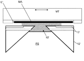
[0041] 本発明の一実施形態において、投影装置1は、投影システムと基板との間の空間を満たすように、比較的高い屈折率を有する液体、たとえば、水によって基板の少なくとも一部が覆われているタイプのものである(図2参照)。さらに、リソグラフィ装置1内の、たとえば、マスクMAと投影システムPSとの間の別の空間10’に液浸液を加えてもよい(図4参照)。液浸技術自体は、投影システムの開口度を増大させるものとして当該分野において周知である。本明細書において使われているような用語「液浸」は、基板のような構造物を液体内に沈めなければならないという意味ではなく、単に、露光中、一方の側の投影システムとその反対側の基板との間に液体があるということを意味するものである。たとえば、投影装置は、欧州特許公開第1429188A2号に記載されている装置と同様の構成または異なる構成を有することができる。この特許公開は言及によりその全体が本願に組み込まれている。
[0041] In one embodiment of the present invention, the projection apparatus 1 covers at least a part of the substrate with a liquid having a relatively high refractive index, for example, water, so as to fill a space between the projection system and the substrate. This is a known type (see FIG. 2). Furthermore, immersion liquid may be added to another
[0042] 図2は、図1の投影装置の細部を示している。図2は、投影システムPSの少なくとも一部に接している液浸スペース10を示す。特に、図2において、液浸スペース10は、投影システムPSの最終光学素子PLと、基板テーブルWT上に置かれた基板Wまたは基板状オブジェクトWとの間に延在している。投影装置1は、注入/排出口13を備える液浸システムを有する。使用中、液浸システムは、注入/排出口13を介して、比較的屈折率の高い液体11、たとえば、水を液浸スペース10に注入する。このような液体には、投影ビームの放射の波長が空気や真空状態の場合よりも短くなるという効果があり、より細かい特徴を解像することが可能となる。投影システムの解像限界が、とりわけ、投影ビームの波長および投影システムの開口数によって決まることはよく知られている。この液体があることもまた、有効な開口数を増大させるものとみなされうる。さらに、開口数が固定されている場合は、この液体は、フィールドの深さを増すのに有効である。
FIG. 2 shows details of the projection apparatus of FIG. FIG. 2 shows an
[0043] 投影装置の構成は、実質的に非接触のシールを最終光学素子PLの画像フィールドの周囲を囲むように基板Wに形成し、その液体を、投影システムPSに面する基板の第1の表面と投影システムPSの最終光学素子との間の空間を満たす範囲に留めるようにすることができる。リザーバは、液浸スペース10を提供するものであり、投影システムPSの最終光学素子PLの下のその周囲を囲む位置に配置されているシール部材12、たとえば、「液浸フード」によって形成することができる。従って、液浸システムは、基板Wの局部上のみ、浸液を供給するよう構成することができる。シール部材12は、投影システムPSの最終光学素子PLと基板Wとの間の空間を液体で満たすための液体供給システムの一部を形成することができる。この液体は、最終光学素子PLの下に位置する、シール部材12内の空間に注入される。シール部材12は、投影システムPSの最終光学素子PLの少し上まで延在していることが好ましく、その液体は、液体のバッファが設けられるよう最終光学素子PLの上まで達する。シール部材12は、上端において投影システムPSまたはその最終光学素子PLの形状に密接に適合する内周を有することができ、内周は、たとえば、円形としてよい。底部において、内周は、画像フィールドの形状(たとえば、長方形)に密接に適合しているが、必ずしも密接に適合している必要はない。シール部材12は、投影システムPSに対するXY面において実質的に静止状態にすることができるが、Z方向(光学軸の方向)においては幾分相対的な動きがありうる。シールは、液浸スペース10に浸液11を閉じ込めるために、シール部材12と基板Wの表面との間に形成することができる。このシールは、非接触シールであることが好ましく、ガスシール(図示せず)であってもよい。
[0043] The configuration of the projection apparatus is such that a substantially non-contact seal is formed on the substrate W to surround the image field of the final optical element PL, and the liquid is first in the substrate facing the projection system PS. The space between the surface of the projection system and the final optical element of the projection system PS can be kept within a range. The reservoir provides an
[0044] また、基板テーブルWTには、カバープレートまたはエッジシール部材17を設けることができる。このようなエッジシール部材17は、基板Wの上部の第1の表面と実質的に同一平面上にある上部(図示のとおり)の第1の表面を有することができ、基板のエッジ部が最終光学素子PLの下へ移動したときに液体が突然失われることがないよう基板Wのエッジ部に密接している。それでもなお、この基板のエッジ部とエッジシール部材との間の空間への液体の損失は幾分起こりうる。
In addition, a cover plate or an
[0045] もちろん、図2に示される構成全体が上下逆に配置され、エッジシール部材および基板の下面が投影システムに面し、実質的に同一平面上となっている構成もある。そのため、これらの面を、上面ではなく、投影システムに面する第1の表面という。本明細書における上面および下面の言及もまた、適宜、上下が逆の構成におけるそれぞれ下面および上面の言及とみなすことができる。 Of course, there is a configuration in which the entire configuration shown in FIG. 2 is arranged upside down, and the edge seal member and the lower surface of the substrate face the projection system and are substantially on the same plane. Therefore, these surfaces are not the top surface but the first surface that faces the projection system. References to the upper and lower surfaces herein may also be considered as references to the lower and upper surfaces, respectively, in an upside down configuration, as appropriate.
[0046] このような装置を使用して、液体供給システム(たとえば、液浸スペース10)を基板Wのエッジ部上に配置することができ、また、基板Wから完全に離れるよう移動させることさえも可能である。これにより、本装置によりデバイス製造方法が行われる際に、基板Wのエッジ部を結像することができる。 [0046] Using such an apparatus, a liquid supply system (eg, immersion space 10) can be placed on the edge of the substrate W, or even moved completely away from the substrate W. Is also possible. Thereby, when the device manufacturing method is performed by this apparatus, the edge portion of the substrate W can be imaged.
[0047] エッジシール部材17は、様々な態様で設けることができる。たとえば、基板テーブルWTと一体部分を形成してもよく、あるいは、たとえば真空吸引を使用して、または電磁力を使用して、基板テーブルの残余部分に一時的に取り付けてもよい。また、エッジシール部材17は、いくつかの個別の部分から形成することもでき、これらの部分はそれぞれ、基板Wのエッジ部の一部を取り囲んでいる。
[0047] The
[0048] 一実施形態によると、投影装置は、少なくとも1つの液浸スペース10と、その液浸スペース10を少なくとも部分的に浸液11で充たすよう構成されているそれぞれの液浸システムとを備える。投影装置は、その装置が基板Wに放射のパターンの付いたビームを投影するために使用される前に、リンス液11で液浸スペース10の少なくとも一部をリンスするよう構成することができる。たとえば、一実施形態において、投影装置は、この装置が比較的長いアイドル動作モードにある間、液浸スペースの少なくとも一部をリンスするよう構成されている。投影装置は、基板に対してパターンの付いた放射ビームを投影するまで実質的に継続して液浸スペースをリンスするよう構成することができる。
[0048] According to one embodiment, the projection device comprises at least one
[0049] 投影装置が浸液11で液浸スペースをリンスするよう構成することが効果的である。その場合、浸液とリンス液は単に同一の液体11であり、その結果、液浸スペースに特定の洗浄液を供給するための特別な洗浄装置を投影装置に設ける必要がなくなる。 It is effective that the projection apparatus is configured to rinse the immersion space with the immersion liquid 11. In that case, the immersion liquid and the rinsing liquid are simply the same liquid 11, and as a result, it is not necessary to provide a special cleaning device for supplying a specific cleaning liquid to the immersion space in the projection apparatus.
[0050] 一実施形態において、投影装置は、液浸スペース10のリンスを行っている間、液浸スペース10、および/または、液浸スペース10に隣接する位置に、オブジェクトを設け、装置が基板のターゲット部分にパターンの付いた放射ビームを投影するために使用される前に、そのオブジェクトを取り除くよう構成することができる。このオブジェクトとしては、たとえば、未加工の(被覆されていない)ウェーハ、ダミーウェーハまたはウェーハ状オブジェクトが含まれうる。たとえば、図1に示されるとおり、投影装置は、この装置が通常の(レジストコートされている)基板のターゲット部分にパターンの付いた放射ビームを投影するために使用されるときにそのオブジェクトを保存するための少なくとも1つの保存スペースまたはコンパートメント22、Hを備えることができる。この保存スペースまたはコンパートメント22、Hは、装置の中のまたはその付近の様々な場所に設けることができる。たとえば、このような保存スペースまたはコンパートメントは、図1のボックス22に概略的に示されているとおり、装置の基板ステージ2の中またはその付近に配置することができる。保存スペースまたはコンパートメントは、様々な態様で配置することができ、閉鎖可能な容器、基板保存ボックス、基板ロボットグリッパまたはあらゆるその他の適切な基板保持体または基板保存手段を含むことができる。保存スペースまたはコンパートメントは投影装置1内、たとえば、液浸システムの付近に配置されていることが好ましい(基板操作部については以下に説明する。)。
In one embodiment, the projection apparatus provides an object at a position adjacent to the
[0051] また、保存スペースまたはコンパートメントは、投影装置1の基板ステージ2の外に配置されている基板操作部Hに含まれるかまたはその一部とすることもできる。この基板操作部H自体は当業者には既知のものである。通常、基板操作部Hは、投影装置1の周辺環境から1つ以上の基板を受け取り、この基板を一時的に保存し、これを基板支持体WTに移動させるものであり、その後、この基板が投影システムPSにより照射される。本実施形態において、たとえば、基板操作部Hが、1つ以上の基板、ダミー基板および/または基板状オブジェクトがリンス処理時、たとえば、投影装置1のアイドル動作期間中にそれぞれの基板テーブルWTに配置される前に、所望の時間の間、これらを保持または保存するよう構成することができる。 [0051] Further, the storage space or compartment may be included in or part of the substrate operation unit H arranged outside the substrate stage 2 of the projection apparatus 1. The substrate operation unit H itself is known to those skilled in the art. Usually, the substrate operation unit H receives one or more substrates from the surrounding environment of the projection apparatus 1, temporarily stores the substrates, and moves them to the substrate support WT. Illuminated by the projection system PS. In the present embodiment, for example, the substrate operating unit H is arranged on each substrate table WT when one or more substrates, dummy substrates, and / or substrate-like objects are rinsed, for example, during an idle operation period of the projection apparatus 1. These can be configured to be retained or stored for a desired amount of time before being done.
[0052] その上、装置1は、かかる保存スペースまたはコンパートメント22、Hから基板保持体WTまで、またはその反対に基板Wを移動させるよう配置または構成された機構(特に図示せず)を含むことができる。このような機構は当業者には既知のものである。たとえば、基板操作部Hおよび基板保持体WTは、これらの間で基板を移動させるために様々な態様で配置または構成することができる。たとえば、基板、ダミー基板または基板状オブジェクトを所望の位置からまたは所望の位置へ移動させるために1つ以上のロボットアーム、コンベヤー、輸送手段またはその他の移動機構を設けることができる。
[0052] Moreover, the apparatus 1 includes a mechanism (not specifically shown) arranged or configured to move the substrate W from such storage space or
[0053] さらに、投影装置は、その装置が通常の(レジストコートされた)基板上にパターンの付いた放射ビームを転写するために実際に使用される前に、液浸スペースのリンス中に紫外線でその空間を照射する少なくとも1つの紫外線源を備えることができる。たとえば、上述の放射源SOをその紫外線源となるよう配置および構成してもよい。一方、リンス中に紫外線で液浸スペース10を照射するために1つ以上の異なる放射源を設けることもできる。
[0053] In addition, the projection apparatus is exposed to ultraviolet light during the immersion space rinse before the apparatus is actually used to transfer a patterned beam of radiation onto a normal (resist coated) substrate. At least one ultraviolet light source for illuminating the space. For example, the radiation source SO described above may be arranged and configured to be the ultraviolet ray source. On the other hand, one or more different radiation sources can be provided for irradiating the
[0054] 図1または図2に示される実施形態では、液浸スペース10は、使用時、一方の側の基板、ダミー基板、基板状オブジェクトWおよび/または基板テーブルもしくは保持体WT、17の少なくとも一部と、その反対側の投影システムPSとの間に延在することができる。ダミー基板は、たとえば、レジスト被覆層が設けられていないベアシリコンウェーハであってもよい。たとえば、上述のとおり、投影装置は、基板保持体WT上のダミー基板または基板状オブジェクトを配置するよう、また、その後、それぞれの液浸スペース10をリンスするよう構成することができる。また、装置は、液浸スペース10が、リンス中に基板保持体WTによって保持されている基板、ダミー基板または基板状オブジェクトWの外側の輪郭に少なくとも届くかまたはこれを含むよう構成することができる。これは図3に示されている。たとえば、投影装置は、(上述のリンス液を使用して)基板支持体WTの少なくとも1つの領域をリンスするように構成することができ、この領域は、基板支持体WTにより保持されている基板、ダミー基板または基板状オブジェクトのエッジ部に沿って、および/または、そのエッジ部の周囲に延在している。その場合、投影装置がその後リソグラフィプロセスの一部として通常の基板を照射するために使用されるときの基板ごとの粒子数が比較的に低くなる。たとえば、投影装置が、液浸スペース10およびリンス液を使用して、基板保持体WTの表面の少なくとも一部および/または基板保持体WTの基板エッジ部シール部材17の表面の少なくとも一部をリンスするよう構成することができる。
[0054] In the embodiment shown in Fig. 1 or Fig. 2, the
[0055] その上、一実施形態において、投影装置は、リンスまたは洗浄工程中、投影システムPSに対して基板保持体WTを移動させるよう構成することができ、これによりリンス中に基板保持体に対する液浸スペース10の位置を変えることができるようになる。これは、図2および図3において矢印QおよびRで示されている。図2において、矢印Qは、投影システムPSおよび液浸スペース10に対する基板保持体WTの横方向の移動を示している。
[0055] Moreover, in one embodiment, the projection apparatus can be configured to move the substrate holder WT relative to the projection system PS during the rinsing or cleaning process, thereby relative to the substrate holder during rinsing. The position of the
[0056] 図3において、矢印Rは、基板および基板状オブジェクトWのエッジ部に沿って、基板または基板状オブジェクトWの周囲を、液浸スペース10の第1の位置101から第2の位置102へ浸液空間10をスキャンしている状態を示している。このように、投影装置のリソグラフィ使用中に基板付近に延在する基板保持体WTまたはそれぞれの基板エッジシール部材17の表面の内部部分を、リンス液でリンスすることができる。また、このように、一方の側の基板または基板状オブジェクトWと、その反対側の基板保持体または選択的なエッジシール部材17との間に延在するエッジスリットEの汚染を比較的良好に除去することができる。
In FIG. 3, an arrow R indicates the second position from the first
[0057] さらに、図3に概略的に示すとおり、使用時に基板Wを取り囲む基板支持体WTの表面が、センサ、位置決め装置、ミラー素子および/またはその他の構成要素等のその他の部品を備えることができる。本発明の一実施形態において、液浸スペースのスキャニングは、液浸システムがこれらの部品21にも到達し、これらの部品21の外面をリンスすることができるものである。
[0057] Further, as schematically shown in FIG. 3, the surface of the substrate support WT surrounding the substrate W in use comprises other components such as sensors, positioning devices, mirror elements and / or other components. Can do. In one embodiment of the present invention, the scanning of the immersion space is such that the immersion system can also reach these
[0058] 基板保持体WTに対する、液浸スペース10をスキャンするための基板保持体WTの移動は、様々な方向に、たとえば、図2および図3に示す方向Q、R、および/または当業者には明らかなその他の様々なスキャン方向に行うことができる。
[0058] Movement of the substrate holder WT to scan the
[0059] 本発明の一実施形態において、投影装置の所定量のアイドル時間を経た後自動的にリンスを開始するよう構成されている。また、投影装置は、所定数のリソグラフィ基板露光(パターンの付いた放射ビームが基板に投影されること)を行った後自動的にリンスを行うよう構成することができる。さらに、一実施形態において、投影装置は、その装置の少なくとも一部が汚染の一定の閾値に達したか否かを判断または推測し、その装置の一部がその汚染閾量に達したと判断または推測された場合にその装置の一部をリンスするよう構成することができる。さらに、図1に概略的に示すとおり、投影装置は、その装置を制御するため、または、少なくともリンスを制御するためのコンピュータ制御CCを備えることができる。このようなコンピュータ制御CCは、たとえば、リンスを開始するタイミングを制御する、リンスを開始するために基板露光の回数を数える、および/または、一定の装置部分が上述の汚染の閾量に達したことを推測または判定するよう構成することができる。コンピュータ制御は、適切なコンピュータソフトウエアによって実現することができる。たとえば、本発明の一実施形態により、コンピュータによってそれが実行されているときに本特許出願に開示されている方法を実施するよう構成されている機械読み取り可能な指示の1つ以上のシーケンスを含むコンピュータプログラムが提供される。 In one embodiment of the present invention, the projector is configured to automatically start rinsing after a predetermined amount of idle time. The projection apparatus can also be configured to automatically rinse after performing a predetermined number of lithography substrate exposures (a patterned radiation beam is projected onto the substrate). Further, in one embodiment, the projection device determines or infers whether at least a portion of the device has reached a certain threshold of contamination and determines that a portion of the device has reached the contamination threshold amount. Or it can be configured to rinse a portion of the device if inferred. Furthermore, as schematically shown in FIG. 1, the projection device can comprise a computer control CC for controlling the device or at least for controlling the rinse. Such a computer control CC, for example, controls when to start rinsing, counts the number of substrate exposures to initiate rinsing, and / or certain device parts have reached the threshold amount of contamination described above. It can be configured to guess or determine. Computer control can be realized by suitable computer software. For example, in accordance with one embodiment of the present invention, includes one or more sequences of machine-readable instructions configured to perform the methods disclosed in this patent application when it is being executed by a computer A computer program is provided.
[0060] 図4に概略的に示される別の実施形態において、液浸スペース10’は、少なくとも、一方の側のパターニングデバイスMAおよび/またはパターニングデバイス保持体MTと、その反対側の投影システムとの間に延在させることができる。その場合、たとえば、投影装置は、ダミーパターニングデバイスまたはパターニングデバイス状オブジェクトをパターニングデバイス保持体上に配置し、続いて、それぞれの液浸スペースをリンスするよう構成することができる。また、投影装置が、たとえば、図2と図4の実施形態を組み合わせることにより、ウェーハステージの液浸スペースおよびパターニングデバイスステージの液浸スペースを備えうることは明らかである。 [0060] In another embodiment schematically shown in FIG. 4, the immersion space 10 'comprises at least the patterning device MA and / or patterning device holder MT on one side and the projection system on the opposite side. Can be extended between. In that case, for example, the projection apparatus can be configured to place a dummy patterning device or patterning device-like object on the patterning device holder and subsequently rinse the respective immersion space. It is also clear that the projection apparatus can comprise an immersion space for the wafer stage and an immersion space for the patterning device stage, for example by combining the embodiments of FIGS.
[0061] また、一実施形態では、投影装置は、少なくとも2つの基板保持体WTを含むことができる。その場合、投影装置は、各基板支持体WTを、少なくとも、液浸スペースが一方の側の基板保持体WTの少なくとも一部とその反対側の投影装置PSとの間に延在するように第1の位置および投影装置PSから離れたそれぞれの第2の位置に移動させるよう構成することができる。第2の位置は、各基板保持体および基板操作部H(図1を参照)との間で基板を移動させるために、たとえば、基板操作部Hの近くにすることができる。さらなる実施形態によると、投影装置は、続いて、これらの基板保持体WTを第1の位置に移動させ、その位置およびその付近においてリンス液で少なくとも部分的にリンスを行うよう構成することができる。あるいは、投影装置は、基板保持体が第2の位置にあるときに少なくとも部分的に洗浄するよう構成されている1つ以上の洗浄装置を備えることができる。このような洗浄装置20は、図1に概略的に示されており、たとえば、基板保持体が第2の位置またはその付近にあるときにリンス流体で基板保持体をリンスすることができるよう配置にしてもよい。洗浄装置20は、各液浸スペースを作成および適用することにより、前記液浸システムと同様に機能することでき、または、異なる態様で機能することもできる。さらに、洗浄装置20は、適切な洗浄液に各基板保持体を完全に浸すよう構成してもよい。
[0061] In an embodiment, the projection apparatus may include at least two substrate holders WT. In that case, the projection apparatus includes each substrate support WT so that at least a liquid immersion space extends between at least a part of the substrate holder WT on one side and the projection apparatus PS on the opposite side. It can be configured to move to a first position and a respective second position remote from the projection device PS. The second position can be, for example, near the substrate operation unit H in order to move the substrate between each substrate holder and the substrate operation unit H (see FIG. 1). According to a further embodiment, the projection device can then be configured to move these substrate holders WT to the first position and at least partially rinse with a rinsing liquid at and near that position. . Alternatively, the projection device may comprise one or more cleaning devices configured to at least partially clean when the substrate holder is in the second position. Such a
[0062] さらに、投影装置は、様々な基板支持体のうちいずれが最も汚染する可能性が高く、最初にリンスまたは洗浄を行うべきかを判定するよう構成することができる。この構成において、投影装置は、汚染される可能性が最も高いと判明した基板保持体を最初にリンスまたは洗浄することができる。 [0062] Further, the projection apparatus can be configured to determine which of the various substrate supports is most likely to be contaminated and should be rinsed or cleaned first. In this configuration, the projection apparatus can first rinse or clean the substrate holder found to be most likely to be contaminated.
[0063] 図1乃至図3に示す液浸型の投影装置は、使用時において、汚染を防止または低減する方法を実行することができる。その目的のため、投影装置を使用してレジストコート基板上にパターンの付いた放射ビームを投影する前に、液浸スペース10の少なくとも一部をリンス液、好ましくは、浸液でリンスする。これにより、液浸スペース10に対しては、投影装置を使用して基板のターゲット部分にパターンの付いた放射ビームを転写するためのリソグラフィプロセスが実行されるまで、この投影装置のアイドル動作モード中、実質的に継続して単にリンスを行うことができる。あるいは、たとえば、バクテリアを活動不能にするかまたは死滅させるために、液浸スペースおよび/またはリンス液の少なくとも一部が紫外線により照射される。一実施形態において、浸液は、超音波洗浄バスに形態を変えることができる。別の実施形態においては、浸液は超音波洗浄バスに形態を変えない。即ち、これは、投影装置1が浸液を超音波洗浄液に変えるよう構成された超音波トランスミッタを備えていない実施形態である。
The immersion type projector shown in FIGS. 1 to 3 can execute a method for preventing or reducing contamination during use. For that purpose, at least a part of the
[0064] 投影装置1のアイドル動作モードは、様々なアイドル時間を含むことができる。たとえば、投影装置は、瞬間的な基板スループット、投影装置1への基板の供給の一時停止、その装置の停止時間、その装置の一定の保守期間または別の期間といった様々な状況のためにデバイス製造装置においてアイドル状態になりうる。 [0064] The idle operation mode of the projection apparatus 1 can include various idle times. For example, the projection apparatus may produce devices for various situations such as instantaneous substrate throughput, suspension of substrate supply to the projection apparatus 1, stop time of the apparatus, a certain maintenance period or another period of the apparatus. It can become idle in the device.
[0065] 図2および図3に示すとおり、ダミー基板または基板状オブジェクトWは、たとえば、基板保持体WTの少なくとも一部をリンスするために浸液空間をリンス液でリンスするときに基板保持体WT上に供給することができる。たとえば、使用時において、リンスを行う前に、ダミー基板または基板状オブジェクトWをその原位置(in-situ)であるコンパートメント22から移動させる、あるいは、基板操作部Hから基板保持体WTに移動させることができる。
[0065] As shown in FIGS. 2 and 3, the dummy substrate or the substrate-like object W is, for example, a substrate holder when rinsing the immersion space with a rinse liquid in order to rinse at least a part of the substrate holder WT. It can be supplied on the WT. For example, in use, before rinsing, the dummy substrate or the substrate-like object W is moved from the in-
[0066] また、基板保持体WTにエッジシール部材17を設けることができる。その場合、基板保持体WTのエッジシール部材17の上面またはその一部を浸液システムでリンスすることができる。
Further, the
[0067] リンスを行った後、ダミー基板または基板状オブジェクトをリソグラフィ製造方法で投影システムPSにより照射される実際の基板と交換することができる。たとえば、ダミー基板または基板状オブジェクトWは、リソグラフィ製造方法の実施中に、たとえば、その原位置(in-situ)であるコンパートメント22または基板操作部Hといった適切な保存コンパートメントに保存することができる。リソグラフィ製造方法を行った後、たとえば、投影装置が比較的長いアイドル動作モードに入った場合、ダミー基板または基板状オブジェクトを再度、基板保持体WT上に配置することができ、実質的に継続したリンスを繰り返すことができる。
[0067] After rinsing, the dummy substrate or substrate-like object can be replaced with an actual substrate irradiated by the projection system PS in a lithographic manufacturing method. For example, the dummy substrate or substrate-like object W can be stored in a suitable storage compartment, for example, the
[0068] また、液浸スペース10の位置はリンス処理中に変えることができる。たとえば、投影装置は、液浸システムおよび/または投影システムPSに対して基板保持体WTを移動させることができ、その結果、液浸スペース10は、基板保持体(および/または基板エッジシール17またはその他のコンポーネント21)の別の位置に到達し、そこから汚染を除去することができる。このように、好ましくは、投影装置のリソグラフィ使用中にも使用される浸液を単に使用して、液浸システムにより投影装置の少なくとも一部の洗浄またはリンスが行われる。上述の結果として、一実施形態では、液浸システムが基板保持体WTまたはその付近に延在する少なくとも1つのスリットまたは開口部E、特に、一方の側の基板または基板状オブジェクトWとその反対側の基板保持体または選択的なエッジシール部材17に延在するエッジスリットEを比較的良好に洗浄またはリンスすることができる。
[0068] Further, the position of the
[0069] 一実施形態において、たとえば、少なくとも1分間、少なくとも1時間またはその他の時間の間、液浸スペースの少なくとも一部について、リンス液、好ましくは、浸液で充填するかまたはこれを使用して洗い流す。たとえば、液浸スペース10の少なくとも一部に対して、1回のアイドル動作期間またはその一部を含む少なくとも1日間実質的に継続して、リンス液で充填するかまたは洗い流すことができる。また、希望により、他のリンス時間を用いることもできる。また、投影装置のアイドル時間中に、液浸スペース10の少なくとも一部について、リンス液で充填するかまたは洗い流して、投影装置の少なくとも1回のその後の起動運転中の基板の汚染を防止また低減することができる。さらに、この方法は、投影装置の液浸スペースを通って浸液が循環することを含むことができる。実質的に汚染のない浸液を提供するために、当業者には明白であるように、浸液を適切な態様でフィルターにかけ、かつ/または、処理することができる。
[0069] In one embodiment, for example, at least a portion of the immersion space is filled or used with a rinsing liquid, preferably an immersion liquid, for at least 1 minute, for at least 1 hour or other time. Wash away. For example, at least a portion of the
[0070] 液浸装置が少なくとも2つの基板保持体WTを含む(たとえば、欧州特許出願第03257072.3号を参照。)場合、これらの基板保持体WTは、その後、第1の位置へ移動し、液浸システムによって洗浄されることがある。あるいは、これらの基板保持体の1つ以上が第2の位置にある場合、その基板保持体WTが選択的な洗浄装置20により洗浄されることもありうる。また、アイドル時間中、基板保持体の1つ以上が適切な液体に完全に沈められ、その保持体を洗浄し、かつ/または、その支持体を汚染のない状態に保つようにする場合もある。さらに、コンピュータ制御CCおよび/またはソフトウエアが、これらの基板保持体のいずれが汚染する可能性が最も高く、最初にリンスまたは洗浄を行う、あるいは、液浸を行うべきかを判断することもある。
[0070] If the immersion apparatus includes at least two substrate holders WT (see, for example, European Patent Application No. 03257072.3), these substrate holders WT are then moved to a first position. May be cleaned by an immersion system. Alternatively, when one or more of these substrate holders are in the second position, the substrate holder WT may be cleaned by the
[0071] 他の方法において、上記のとおり、また、図4に示すとおり、各液浸スペースは、少なくとも、一方の側のパターニングデバイス、ダミーパターニングデバイスまたはパターニングデバイス状オブジェクトMAおよび/またはパターニングデバイス保持体MTとその反対側の投影システムPSとの間に延在している。たとえば、ダミーパターニングデバイスまたはパターニングデバイス状オブジェクトMAは、パターニングデバイス保持体MT上に配置することができ、その後、各液浸スペース10’について、たとえば、投影装置のアイドルモード中にリンスが行われる。投影装置は、ダミーパターニングデバイスまたはパターニングデバイス状オブジェクトがパターニングデバイス保持体上に配置されていないときにこのパターニングデバイスまたはオブジェクトを保存するその原位置(in-situ)である保存スペースまたはコンパートメント(図示せず)を備えることが好ましい。リンスを行った後、ダミーパターニングデバイスまたはパターニングデバイス状オブジェクトを実際のパターニングデバイスに差し替えることができ、この実際のパターニングデバイスを使用して、放射が投影システムPSに入射する前に、その放射にパターンを与える。たとえば、液浸システムは、パターニングデバイス保持体の少なくとも一部を洗浄またはリンスすることができる。また、液浸システムは、パターニングデバイス保持体WTまたはその付近に延在する少なくとも1つのスリットまたは開口部E’(図4参照)を洗浄またはリンスすることができる。投影装置が少なくとも2つのパターニングデバイス保持体WTを備える場合、これらのパターニングデバイス保持体は、上述の複数の基板保持体WTに対する汚染を防止または低減する方法と同様の処理を行うことができる。 [0071] In other methods, as described above, and as shown in FIG. 4, each immersion space has at least one patterning device, dummy patterning device or patterning device-like object MA and / or patterning device holding on one side. It extends between the body MT and the opposite projection system PS. For example, a dummy patterning device or patterning device-like object MA can be placed on the patterning device holder MT, and then each immersion space 10 'is rinsed, for example during the idle mode of the projection apparatus. The projection apparatus includes a storage space or compartment (not shown) that is a in-situ storage of the patterning device or object when the dummy patterning device or patterning device-like object is not placed on the patterning device holder. Preferably). After rinsing, the dummy patterning device or patterning device-like object can be replaced with an actual patterning device, which is used to pattern the radiation before it enters the projection system PS. give. For example, the immersion system can clean or rinse at least a portion of the patterning device holder. The immersion system can also clean or rinse at least one slit or opening E '(see FIG. 4) extending at or near the patterning device holder WT. When the projection apparatus includes at least two patterning device holders WT, these patterning device holders can perform the same processing as the method for preventing or reducing contamination on the plurality of substrate holders WT described above.
[0072] 装置1が少なくとも2つのパターニングデバイス支持体MTを備える場合、これらの支持体MTがその後、上述の少なくとも2つの基板保持体WTの処理と同様に、それぞれの第1の位置に移動し、それぞれの浸液システムにより洗浄されることもある。また、これらのパターニングデバイス支持体MTの1つ以上がそれぞれの第2の位置にあるとき、そのパターニングデバイス支持体MTが選択的な洗浄装置(図示せず)によって洗浄される場合もある。さらに、コンピュータ制御CCおよび/またはソフトウエアが、これらパターニングデバイス支持体MTのいずれが汚染される可能性が最も高く、最初にリンスまたは洗浄を行うべきであるかを判定する場合もある。 [0072] If the apparatus 1 comprises at least two patterning device supports MT, these supports MT are then moved to their respective first positions, similar to the processing of the at least two substrate holders WT described above. And may be cleaned by the respective immersion system. Also, when one or more of these patterning device supports MT are in their respective second positions, the patterning device support MT may be cleaned by a selective cleaning apparatus (not shown). In addition, the computer control CC and / or software may determine which of these patterning device supports MT is most likely contaminated and should be rinsed or cleaned first.
[0073] 本発明は、リソグラフィ装置の起動時の汚染を低減することおよび/または一まとまりの基板のうちの第1の基板上の汚染を低減することを目的としうるものである。たとえば、第1の基板が機械アイドル時間後に投影装置により加工されるときに、たとえば、粒子数において汚染のピークを示す場合がある。この粒子数は、「ウェーハパスごとの粒子」(PWP)数として表すことができる。さらに、本発明は、予測されるバクテリアの成長を低減することもできる。たとえば、リンスは、各装置部分(たとえば、基板保持体)上に継続的な流体の流れを与えることができ、これにより、バクテリアの成長を防止することができる。さらに、選択的なin-situ紫外線洗浄処理を適用することにより、バクテリアを除去するためのH2O2洗浄方法の利用を避けることができる。H2O2の使用は、投影装置の一定の構成部品に存在しうるTiNに適合しない。 The present invention may be aimed at reducing contamination at start-up of a lithographic apparatus and / or reducing contamination on a first substrate of a group of substrates. For example, when a first substrate is processed by a projection device after a machine idle time, it may exhibit a contamination peak, for example, in particle count. This number of particles can be expressed as the number of “particles per wafer pass” (PWP). Furthermore, the present invention can also reduce the expected bacterial growth. For example, rinsing can provide a continuous fluid flow over each device portion (eg, substrate holder), thereby preventing bacterial growth. Furthermore, by applying a selective in-situ UV cleaning process, the use of a H 2 O 2 cleaning method for removing bacteria can be avoided. The use of H 2 O 2 is not compatible with TiN that may be present in certain components of the projection apparatus.
[0074] 通常、デバイス製造方法において、レジストコートされたウェーハは、投影装置により照射される。レジスト被覆されたウェーハを使用することで、そのレジストおよびレジストが基板に適用される態様に応じて、汚染レベルPWPが上昇する場合がある。これは図5に示されている。図5は、液浸型の装置の基板ステージに関する様々な実験的試運転の結果を示すものである。まず、PWP値は、投影装置の基板保持体WTに搭載され、また、その基板保持体WTから取り外されたベアシリコンウェーハを使用して測定された。各数値は比較的低く、図5に黒塗丸印AAでされている。 [0074] Normally, in a device manufacturing method, a resist-coated wafer is irradiated by a projection apparatus. Using a resist coated wafer may increase the contamination level PWP depending on the resist and the manner in which the resist is applied to the substrate. This is illustrated in FIG. FIG. 5 shows the results of various experimental trials relating to the substrate stage of the immersion type apparatus. First, the PWP value was measured using a bare silicon wafer mounted on the substrate holder WT of the projection apparatus and removed from the substrate holder WT. Each numerical value is relatively low and is indicated by a black circle AA in FIG.
[0075] その後まもなく、一まとまりのレジスト被覆されたウェーハ(ゼロ線量)を投影装置で露光した。次に、さらなる8つのベアSiウェーハを使用してPWPを再度テストした。8件のテスト結果では、図5に黒塗四角印BBで示されるとおり、PWPが上昇していることが分かる。 Shortly thereafter, a batch of resist-coated wafers (zero dose) was exposed with a projector. The PWP was then retested using an additional 8 bare Si wafers. From the eight test results, it can be seen that the PWP has increased as shown by the black squares BB in FIG.
[0076] 約9時間半もの投影装置のその後のアイドル期間中に、液浸システムおよび浸液を利用して、液浸スペースのリンスを開始した。その後、さらなる5つのベアウェーハを使用してPWPを再度テストした。その結果は、図5の黒塗三角印CCとして示されており、液浸スペース10のリンスが所望の低いPWPをもたらすことを証明するものであった。
[0076] During the subsequent idle period of the projector for approximately nine and a half hours, rinsing of the immersion space was initiated using the immersion system and immersion liquid. The PWP was then retested using an additional 5 bare wafers. The result is shown as black triangle CC in FIG. 5 and proves that rinsing the
[0077] 特に、投影装置の動作期間に露光される第1のウェーハのPWPは、通常、その後に露光されたウェーハのものよりも大幅に高くなりうる。本発明に従い、液浸システムが、基板保持体WTおよび/もしくはパターニングデバイス保持体MT、ならびに/または、エッジシール部材17、スリットE、E’、センサおよびその他の構成部品といったこれらの一部に対する長期にわたるまたは実質的に継続した湿式ホバリングがPWPを低下させることが例証された。
[0077] In particular, the PWP of the first wafer exposed during the operation period of the projection apparatus can typically be significantly higher than that of the subsequently exposed wafer. In accordance with the present invention, an immersion system may be used for extended periods of time for some of these, such as substrate holder WT and / or patterning device holder MT, and / or
[0078] 一実施形態において、投影装置は、基板保持体(またはその部分のチャック)に対しシリコンウェーハを搭載し、この基板支持体に対して湿潤ホバリングを開始するよう構成することができる。たとえば、投影装置に、浸液システムの流体供給口13を塞ぐいわゆるクロージングディスクまたは適切なクロージング部材が設けられている場合、リンスは、最少数のクロージングディスクエクスチェンジ(Closing Disk Exchange)で行うことができる。リンス処理は、所定の「機械アイドル」時間(「スクリーンセーバー」のような状態)の後、および/または一定数の露光を行った後、自動的に開始することができる。たとえば、ウェーハ操作部Hの「ビザボックス状容器」、または他の位置に保存されている数多くの未使用のウェーハをこの洗浄動作に使用することができる。
[0078] In an embodiment, the projection apparatus may be configured to mount a silicon wafer on a substrate holder (or a chuck of the portion thereof) and initiate wet hovering on the substrate support. For example, if the projection device is provided with a so-called closing disk or a suitable closing member that plugs the
[0079] 投影装置が2つ以上の基板保持体またはチャックを備える場合、これらの基板保持体またはチャックはそれぞれ、一定の時間ごとに交換することによって洗浄するようにしてもよい。さらに、コンピュータ制御CCおよび/またはソフトウエアによって、最後に洗浄した基板保持体またはチャックの記録を維持し、次回に他の基板保持体またはチャックから開始するようにしてもよい。 [0079] When the projection apparatus includes two or more substrate holders or chucks, each of these substrate holders or chucks may be cleaned by replacing them at regular intervals. Further, the computer control CC and / or software may maintain a record of the last cleaned substrate holder or chuck and may start with another substrate holder or chuck next time.
[0080] また、好ましくは、投影装置のアイドル時間中に、基板保持体もしくはチャックまたはその付近でのバクテリアの成長を防止するために、基板支持体またはチャックを、浸液、たとえば、純水(UPW)で継続的に洗い流すことができる。空気にさらされた動かない水のたまりを避けることが好ましい。さらに、水で洗い流している間の一定時間、放射源SOをオンにして、基板保持体またはチャックの紫外線誘導オゾン洗浄を行うようにしてもよい。また、このオゾン洗浄は、流出レジストといった有機性の化学汚染やバクテリアを「死滅」させるのに効果的となりうる。この洗浄処理中には、ベア基板または基板状オブジェクトが処理中の基板保持体上に置かれている。 [0080] Also preferably, during the idle time of the projection apparatus, the substrate support or chuck is immersed in an immersion liquid, for example pure water (in order to prevent bacterial growth on or near the substrate holder or chuck). UPW) can be washed away continuously. It is preferable to avoid stagnant water pools exposed to air. Further, the radiation source SO may be turned on for a certain period of time while washing with water to perform ultraviolet-induced ozone cleaning of the substrate holder or the chuck. This ozone cleaning can also be effective in “killing” organic chemical contamination such as spilled resist and bacteria. During this cleaning process, a bare substrate or substrate-like object is placed on the substrate holder being processed.
[0081] たとえば、投影装置のアイドル時間中、各基板保持体または受け台を純水で継続的に洗い流することで、粒子による汚染を低減させ、バクテリアの成長を回避することができる。浸液は常時流れている状態にあることが好ましい。 For example, by continuously washing each substrate holder or cradle with pure water during the idle time of the projection apparatus, contamination by particles can be reduced and bacterial growth can be avoided. It is preferable that the immersion liquid is always flowing.
[0082] また、特に、放射源SOが紫外線源である場合には、アイドル時間中、この放射光を使用して、in-situ洗浄を行うようにしてもよい。水中で発生したオゾンは、有機物およびバクテリアの成長を除去する効果的な手段となる。 [0082] In particular, when the radiation source SO is an ultraviolet ray source, in-situ cleaning may be performed using this radiation during the idle time. Ozone generated in water provides an effective means of removing organic and bacterial growth.
[0083] また、ベアウェーハと同様の形状を有するベアダミー基板またはオブジェクトを、アイドル時間の洗浄処理中に基板保持体WTに配置することができる。液浸型の装置には、ダミー基板専用のその原位置(in-situ)である保存コンパートメントを設けることができる。 In addition, a bare dummy substrate or object having the same shape as that of the bare wafer can be placed on the substrate holder WT during the idle time cleaning process. An immersion type apparatus can be provided with a storage compartment that is dedicated in-situ for the dummy substrate.
[0084] 本明細書では、IC製造におけるリソグラフィ装置の使用について具体的に言及しているが、本明細書記載のリソグラフィ装置が、集積光学システム、磁気ドメインメモリ用のガイダンスパターンおよび検出パターン、フラットパネルディスプレイ、液晶ディスプレイ(LCD)、薄膜磁気ヘッドといった他の用途を有することは、明らかである。当業者には当然のことであるが、そのような別の用途においては、本明細書で使われている用語「ウェーハ」または「ダイ」はすべて、それぞれより一般的な用語「基板」または「ターゲット部分」と同義であると考えればよい。本明細書に記載した基板は、露光の前後に、たとえば、トラック(通常、基板にレジスト層を塗布し、露光されたレジストを現像するツール)、メトロロジーツール、および/またはインスペクションツールで処理されてもよい。適用可能な場合には、本明細書中の開示物を上記のような基板プロセシングツールおよびその他の基板プロセシングツールに適用してもよい。さらに、基板は、たとえば、積層ICを作るために、複数回処理されてもよいので、本明細書で使われる基板という用語が、既に多重処理層を包含している基板を表すものとしてもよい。 [0084] Although this specification specifically refers to the use of a lithographic apparatus in IC manufacture, the lithographic apparatus described herein is an integrated optical system, guidance and detection patterns for magnetic domain memories, flats Obviously, it has other uses such as panel displays, liquid crystal displays (LCDs), thin film magnetic heads. As will be appreciated by those skilled in the art, in such other applications, the terms “wafer” or “die” as used herein are all generic terms “substrate” or “die”, respectively. What is necessary is just to think that it is synonymous with a "target part." The substrate described herein is processed before and after exposure, for example, with a track (usually a tool that applies a resist layer to the substrate and develops the exposed resist), a metrology tool, and / or an inspection tool. May be. Where applicable, the disclosure herein may be applied to substrate processing tools such as those described above and other substrate processing tools. Further, since the substrate may be processed multiple times, for example, to make a stacked IC, the term substrate used herein may refer to a substrate that already contains multiple processing layers. .
[0085] 光学リソグラフィの分野での本発明の実施形態の使用について既に具体的に説明してきたが、言うまでもなく、本発明は、他の用途、たとえば、インプリントリソグラフィに使われてもよく、さらに状況が許すのであれば、光学リソグラフィに限定されることはない。インプリントリソグラフィにおいては、パターニングデバイス内のトポグラフィが基板上に創出されたパターンを画定する。パターニングデバイスのトポグラフィは、基板に与えられたレジスト層の中にプレス加工され、基板上では、電磁放射、熱、圧力、またはそれらの組合せによってレジストを硬化させることができる。パターニングデバイスは、レジストが硬化した後、レジスト内にパターンを残してレジストの外へ移動される。 [0085] While the use of embodiments of the present invention in the field of optical lithography has been specifically described, it will be appreciated that the present invention may be used in other applications, such as imprint lithography, If the situation allows, it is not limited to optical lithography. In imprint lithography, the topography within the patterning device defines the pattern created on the substrate. The topography of the patterning device is pressed into a resist layer applied to the substrate, whereupon the resist can be cured by electromagnetic radiation, heat, pressure, or a combination thereof. The patterning device is moved out of the resist leaving a pattern in it after the resist is cured.
[0086] 本明細書で使われている用語「放射」および「ビーム」は、紫外線(UV)(たとえば、約365、355、248、193、157、または126nmの波長を有する)、および極紫外線(EUV)(たとえば、5〜20nmの範囲の波長を有する)などのあらゆる種類の電磁放射、ならびにイオンビームや電子ビームなどの微粒子ビームを包含している。 [0086] The terms "radiation" and "beam" as used herein refer to ultraviolet (UV) (eg, having a wavelength of about 365, 355, 248, 193, 157, or 126 nm), and extreme ultraviolet All kinds of electromagnetic radiation such as (EUV) (for example having a wavelength in the range of 5-20 nm), as well as particulate beams such as ion beams and electron beams are included.
[0087] 用語「レンズ」は、状況が許すのであれば、屈折、反射、磁気、電磁気、および静電型光学部品を含むさまざまな種類の光学系のどれか1つまたは組合せを指すことができる。 [0087] The term "lens" can refer to any one or combination of various types of optical systems, including refractive, reflective, magnetic, electromagnetic, and electrostatic optics, if the situation allows. .
[0088] 本発明の実施形態の使用について既に具体的に説明してきたが、言うまでもなく、本発明は、記載される以外の態様で実施されうる。たとえば、本発明は、上記に開示されている方法を記載する機械読み取り可能な指示の1つ以上のシーケンスを含むコンピュータプログラム、またはそのようなコンピュータプログラムが記憶されているデータ記憶媒体(たとえば、半導体メモリ、磁気ディスクまたは光ディスク)の形態を取りうる。 [0088] While the use of embodiments of the present invention has been specifically described, it will be appreciated that the present invention may be practiced otherwise than as described. For example, the present invention relates to a computer program that includes one or more sequences of machine-readable instructions that describe the methods disclosed above, or a data storage medium (eg, a semiconductor) on which such a computer program is stored. Memory, magnetic disk or optical disk).
[0089] 本発明の1つ以上の実施形態を上述のタイプの液浸リソグラフィ装置に適用することでき、また、浸液をバスの形態で供給するかまたは基板の局所の表面領域のみに提供するかにかかわらず適用することができる。液浸システムは、投影システムと基板および/または基板テーブルとの間の空間に液体を供給する機構とすることができる。また、液浸システムは、1つ以上の構造、1つ以上の液体挿入口、1つ以上の気体挿入口、1つ以上の気体排出口および/または1つ以上の液体注入口のあらゆる組み合わせであって、浸液をその空間に供給し、閉じ込める組み合わせを備えてよい。一実施形態において、その空間の表面を基板および/または基板テーブルの一部に限定してもよく、また、その空間の表面が基板および/または基板テーブルの表面を完全に覆ってもよく、あるいは、その空間が基板および/または基板テーブルを包みこむようにしてもよい。 [0089] One or more embodiments of the invention may be applied to an immersion lithographic apparatus of the type described above, and the immersion liquid may be supplied in the form of a bath or provided only to a local surface area of the substrate. Can be applied regardless. The immersion system may be a mechanism that supplies liquid to a space between the projection system and the substrate and / or substrate table. Also, the immersion system may be any combination of one or more structures, one or more liquid inlets, one or more gas inlets, one or more gas outlets and / or one or more liquid inlets. There may be a combination of supplying and confining immersion liquid to the space. In one embodiment, the surface of the space may be limited to a portion of the substrate and / or substrate table, the surface of the space may completely cover the surface of the substrate and / or substrate table, or The space may enclose the substrate and / or substrate table.
[0090] また、液浸システムは、投影システムとパターニングデバイスおよび/またはパターニングデバイス支持体との間の空間に液体を供給するあらゆる機構としてよい。 [0090] The immersion system may also be any mechanism that supplies liquid to the space between the projection system and the patterning device and / or patterning device support.
[0091] 上記の説明は、限定ではなく例示を目的としたものである。したがって、当業者には明らかなように、添付の特許請求の範囲を逸脱することなく本記載の発明に変更を加えることもできる。 [0091] The descriptions above are intended to be illustrative, not limiting. Thus, it will be apparent to one skilled in the art that modifications may be made to the invention as described without departing from the scope of the claims set out below.
Claims (29)
前記液浸スペースが少なくとも、一方の側の基板、ダミー基板もしくはレジスト被膜層が設けられていない基板状オブジェクトおよび/または基板保持体の少なくとも一部とその反対側の投影システムとの間に延在し、
前記基板保持体上に前記ダミー基板または前記基板状オブジェクトを配置することと、
前記装置を使用して前記放射ビームを基板に投影する前に前記液浸スペースの少なくとも一部をリンスすることと、
前記リンスの完了後に、前記ダミー基板または前記基板状オブジェクトを前記投影システムにより照射される基板に差し替えることと、を含み、
前記リンスは、前記ダミー基板または基板状オブジェクトを囲む基板保持体表面の少なくとも一部及び/又は該基板保持体表面上に配置されたカバープレート又はシール部材のリンスを含む、方法。 A method for preventing or reducing contamination of an immersion type projection apparatus comprising at least one immersion space that is at least partially filled with a liquid when projecting a radiation beam onto a substrate, comprising:
The immersion space extends at least between a substrate on one side, a dummy substrate or a substrate-like object not provided with a resist coating layer and / or a substrate holder and a projection system on the opposite side. And
Placing the dummy substrate or the substrate-like object on the substrate holder;
Rinsing at least a portion of the immersion space before projecting the beam of radiation onto a substrate using the apparatus;
After completion of the rinse, replacing the dummy substrate or the substrate-like object with a substrate irradiated by the projection system;
The rinsing includes rinsing of at least a part of a substrate holder surface surrounding the dummy substrate or substrate-like object and / or a cover plate or a seal member disposed on the substrate holder surface.
前記液浸スペースが少なくとも、一方の側の基板、ダミー基板もしくはレジスト被膜層が設けられていない基板状オブジェクトおよび/または基板保持体の少なくとも一部とその反対側の投影システムとの間に延在し、
前記基板保持体上に前記ダミー基板または前記基板状オブジェクトを配置することと、
前記液浸スペースおよび前記装置の少なくとも一部の少なくとも一方を他方に対して移動させることと、
前記装置を使用して基板のターゲット部分にパターンの付いた放射ビームを投影する前に、前記液体で前記液浸スペースの少なくとも一部をリンスすることと、
前記リンスの完了後に、前記ダミー基板または前記基板状オブジェクトを前記投影システムにより照射される基板に差し替えることと、を含み、
前記リンスは、前記ダミー基板または基板状オブジェクトを囲む基板保持体表面の少なくとも一部及び/又は該基板保持体表面上に配置されたカバープレート又はシール部材のリンスを含む、方法。 A method for preventing or reducing contamination of an immersion type projection apparatus, wherein the apparatus is configured to hold a substrate, a patterning device holder configured to hold a patterning device, and a projection A method comprising: a system; and an immersion system configured to fill at least a portion of the immersion space of the apparatus with liquid,
The immersion space extends at least between a substrate on one side, a dummy substrate or a substrate-like object not provided with a resist coating layer and / or a substrate holder and a projection system on the opposite side. And
Placing the dummy substrate or the substrate-like object on the substrate holder;
Moving at least one of the immersion space and at least a portion of the device relative to the other;
Rinsing at least a portion of the immersion space with the liquid before projecting a patterned beam of radiation onto a target portion of a substrate using the apparatus;
After completion of the rinse, replacing the dummy substrate or the substrate-like object with a substrate irradiated by the projection system;
The rinsing includes rinsing of at least a part of a substrate holder surface surrounding the dummy substrate or substrate-like object and / or a cover plate or a seal member disposed on the substrate holder surface.
少なくとも1つの液浸スペースと、
前記液浸スペースの少なくとも一部を液体で充填するよう構成された液浸システムと、を備え、
前記液浸スペースが、一方の側の基板、ダミー基板もしくはレジスト被膜層が設けられていない基板状オブジェクトおよび/または基板保持体の少なくとも一部と、その反対側の該装置の投影システムの一部との間に延在し、
当該装置が、前記ダミー基板または前記基板状オブジェクトを前記基板保持体に配置し、その後、該装置を使用して基板にパターンの付いた放射ビームを投影する前に、リンス液で前記液浸スペースの少なくとも一部をリンスし、前記リンスの完了後に、前記ダミー基板または前記基板状オブジェクトを前記投影システムにより照射される基板に差し替えるよう構成されており、
前記リンスは、前記ダミー基板または基板状オブジェクトを囲む基板保持体表面の少なくとも一部及び/又は該基板保持体表面上に配置されたカバープレート又はシール部材のリンスを含む、液浸型リソグラフィ装置。 An immersion type lithographic apparatus,
At least one immersion space;
An immersion system configured to fill at least a portion of the immersion space with a liquid, and
The immersion space includes at least a part of a substrate on one side, a dummy substrate or a substrate-like object not provided with a resist coating layer and / or a substrate holder, and a part of the projection system of the apparatus on the opposite side. Extending between and
The apparatus places the dummy substrate or the substrate-like object on the substrate holder, and then uses the apparatus to project the patterned radiation beam onto the substrate before immersing the immersion space with a rinsing liquid. Rinsing at least a portion of the dummy substrate or the substrate-like object after completion of the rinsing, and replacing the substrate irradiated with the projection system,
The immersion type lithographic apparatus, wherein the rinse includes a rinse of at least a part of a surface of a substrate holder surrounding the dummy substrate or the substrate-like object and / or a cover plate or a seal member arranged on the surface of the substrate holder.
前記装置は、該装置が放射ビームを基板上に投影するときに少なくとも部分的に液体で充填されている少なくとも1つの液浸スペースを備え、前記液浸スペースが、一方の側の基板、ダミー基板もしくはレジスト被膜層が設けられていない基板状オブジェクトおよび/または基板保持体の少なくとも一部と、その反対側の該装置の投影システムの一部との間に延在し、
該方法が、該装置を使用して前記ダミー基板または前記基板状オブジェクトを前記基板保持体に配置し、その後、放射ビームを基板に投影する前に液浸スペースの少なくとも一部をリンス液でリンスし、前記リンスの完了後に、前記ダミー基板または前記基板状オブジェクトを前記投影システムにより照射される基板に差し替えることを含み、
前記リンスは、前記ダミー基板または基板状オブジェクトを囲む基板保持体表面の少なくとも一部及び/又は該基板保持体表面上に配置されたカバープレート又はシール部材のリンスを含む、コンピュータプログラム。 One or more of the machine-readable instructions configured to perform a method for preventing or reducing contamination of an immersion projection apparatus when the computer program is being executed by a computer A computer program comprising a sequence,
The apparatus comprises at least one immersion space that is at least partially filled with a liquid when the apparatus projects a radiation beam onto the substrate, the immersion space being a substrate on one side, a dummy substrate Or extending between at least a part of a substrate-like object and / or substrate holder without a resist coating layer and a part of the projection system of the apparatus on the opposite side,
The method uses the apparatus to place the dummy substrate or the substrate-like object on the substrate holder and then rinse at least a portion of the immersion space with a rinsing liquid before projecting the radiation beam onto the substrate. And after completion of the rinsing, replacing the dummy substrate or the substrate-like object with a substrate irradiated by the projection system,
The rinsing includes a computer program including at least a part of a surface of a substrate holder surrounding the dummy substrate or the substrate-like object and / or rinsing of a cover plate or a seal member disposed on the surface of the substrate holder.
Applications Claiming Priority (2)
| Application Number | Priority Date | Filing Date | Title |
|---|---|---|---|
| US11/292,311 | 2005-12-02 | ||
| US11/292,311 US8125610B2 (en) | 2005-12-02 | 2005-12-02 | Method for preventing or reducing contamination of an immersion type projection apparatus and an immersion type lithographic apparatus |
Related Child Applications (1)
| Application Number | Title | Priority Date | Filing Date |
|---|---|---|---|
| JP2010006646A Division JP5237309B2 (en) | 2005-12-02 | 2010-01-15 | Method for preventing or reducing contamination of an immersion projection apparatus and immersion lithography apparatus |
Publications (2)
| Publication Number | Publication Date |
|---|---|
| JP2007158326A JP2007158326A (en) | 2007-06-21 |
| JP4938424B2 true JP4938424B2 (en) | 2012-05-23 |
Family
ID=37806788
Family Applications (2)
| Application Number | Title | Priority Date | Filing Date |
|---|---|---|---|
| JP2006316939A Expired - Fee Related JP4938424B2 (en) | 2005-12-02 | 2006-11-24 | Method for preventing or reducing contamination of an immersion projection apparatus and immersion lithography apparatus |
| JP2010006646A Active JP5237309B2 (en) | 2005-12-02 | 2010-01-15 | Method for preventing or reducing contamination of an immersion projection apparatus and immersion lithography apparatus |
Family Applications After (1)
| Application Number | Title | Priority Date | Filing Date |
|---|---|---|---|
| JP2010006646A Active JP5237309B2 (en) | 2005-12-02 | 2010-01-15 | Method for preventing or reducing contamination of an immersion projection apparatus and immersion lithography apparatus |
Country Status (7)
| Country | Link |
|---|---|
| US (4) | US8125610B2 (en) |
| EP (1) | EP1793276A3 (en) |
| JP (2) | JP4938424B2 (en) |
| KR (3) | KR100826992B1 (en) |
| CN (1) | CN1983034B (en) |
| SG (1) | SG132660A1 (en) |
| TW (2) | TWI397777B (en) |
Cited By (1)
| Publication number | Priority date | Publication date | Assignee | Title |
|---|---|---|---|---|
| JP2010087535A (en) * | 2005-12-02 | 2010-04-15 | Asml Netherlands Bv | Method for preventing or reducing contamination of immersion type projection apparatus and immersion type lithographic apparatus |
Families Citing this family (50)
| Publication number | Priority date | Publication date | Assignee | Title |
|---|---|---|---|---|
| SG2013077797A (en) | 2003-04-11 | 2017-02-27 | Nippon Kogaku Kk | Cleanup method for optics in immersion lithography |
| TWI503865B (en) | 2003-05-23 | 2015-10-11 | 尼康股份有限公司 | A method of manufacturing an exposure apparatus and an element |
| EP1486827B1 (en) * | 2003-06-11 | 2011-11-02 | ASML Netherlands B.V. | Lithographic apparatus and device manufacturing method |
| TWI245163B (en) | 2003-08-29 | 2005-12-11 | Asml Netherlands Bv | Lithographic apparatus and device manufacturing method |
| US7050146B2 (en) | 2004-02-09 | 2006-05-23 | Asml Netherlands B.V. | Lithographic apparatus and device manufacturing method |
| KR101433496B1 (en) | 2004-06-09 | 2014-08-22 | 가부시키가이샤 니콘 | Exposure system and device production method |
| WO2005124833A1 (en) * | 2004-06-21 | 2005-12-29 | Nikon Corporation | Exposure device, exposure device member cleaning method, exposure device maintenance method, maintenance device, and device manufacturing method |
| US8698998B2 (en) | 2004-06-21 | 2014-04-15 | Nikon Corporation | Exposure apparatus, method for cleaning member thereof, maintenance method for exposure apparatus, maintenance device, and method for producing device |
| US7385670B2 (en) * | 2004-10-05 | 2008-06-10 | Asml Netherlands B.V. | Lithographic apparatus, cleaning system and cleaning method for in situ removing contamination from a component in a lithographic apparatus |
| KR101236120B1 (en) * | 2004-10-26 | 2013-02-28 | 가부시키가이샤 니콘 | Substrate processing method, exposure apparatus and method for manufacturing device |
| US20070242248A1 (en) * | 2004-10-26 | 2007-10-18 | Nikon Corporation | Substrate processing method, exposure apparatus, and method for producing device |
| US7362412B2 (en) * | 2004-11-18 | 2008-04-22 | International Business Machines Corporation | Method and apparatus for cleaning a semiconductor substrate in an immersion lithography system |
| US7880860B2 (en) | 2004-12-20 | 2011-02-01 | Asml Netherlands B.V. | Lithographic apparatus and device manufacturing method |
| TW200710616A (en) * | 2005-07-11 | 2007-03-16 | Nikon Corp | Exposure apparatus and method for manufacturing device |
| JP2007173695A (en) * | 2005-12-26 | 2007-07-05 | Sokudo:Kk | Method and system for substrate processing, and substrate processing device |
| JP2007173732A (en) * | 2005-12-26 | 2007-07-05 | Sokudo:Kk | Substrate processing apparatus |
| JP4704221B2 (en) * | 2006-01-26 | 2011-06-15 | 株式会社Sokudo | Substrate processing apparatus and substrate processing method |
| JP2007266074A (en) * | 2006-03-27 | 2007-10-11 | Toshiba Corp | Fabrication process of semiconductor device and oil immersion lithography system |
| JP2007294817A (en) * | 2006-04-27 | 2007-11-08 | Sokudo:Kk | Method, system, and apparatus for processing substrates |
| EP2037486A4 (en) * | 2006-05-18 | 2012-01-11 | Nikon Corp | Exposure method and apparatus, maintenance method and device manufacturing method |
| JP2008004928A (en) * | 2006-05-22 | 2008-01-10 | Nikon Corp | Exposure method and apparatus, maintenance method, and device manufacturing method |
| US7969548B2 (en) * | 2006-05-22 | 2011-06-28 | Asml Netherlands B.V. | Lithographic apparatus and lithographic apparatus cleaning method |
| CN102156389A (en) * | 2006-05-23 | 2011-08-17 | 株式会社尼康 | Maintenance method, exposure method and apparatus, and device manufacturing method |
| JP2007317987A (en) * | 2006-05-29 | 2007-12-06 | Sokudo:Kk | Substrate processing apparatus, and substrate processing method |
| JP5245825B2 (en) * | 2006-06-30 | 2013-07-24 | 株式会社ニコン | Maintenance method, exposure method and apparatus, and device manufacturing method |
| KR20090060270A (en) * | 2006-09-08 | 2009-06-11 | 가부시키가이샤 니콘 | Cleaning member, cleaning method and device manufacturing method |
| US8817226B2 (en) | 2007-02-15 | 2014-08-26 | Asml Holding N.V. | Systems and methods for insitu lens cleaning using ozone in immersion lithography |
| US8654305B2 (en) * | 2007-02-15 | 2014-02-18 | Asml Holding N.V. | Systems and methods for insitu lens cleaning in immersion lithography |
| US7866330B2 (en) | 2007-05-04 | 2011-01-11 | Asml Netherlands B.V. | Cleaning device, a lithographic apparatus and a lithographic apparatus cleaning method |
| US8947629B2 (en) * | 2007-05-04 | 2015-02-03 | Asml Netherlands B.V. | Cleaning device, a lithographic apparatus and a lithographic apparatus cleaning method |
| US7900641B2 (en) * | 2007-05-04 | 2011-03-08 | Asml Netherlands B.V. | Cleaning device and a lithographic apparatus cleaning method |
| US8011377B2 (en) | 2007-05-04 | 2011-09-06 | Asml Netherlands B.V. | Cleaning device and a lithographic apparatus cleaning method |
| US7916269B2 (en) | 2007-07-24 | 2011-03-29 | Asml Netherlands B.V. | Lithographic apparatus and contamination removal or prevention method |
| US20090025753A1 (en) * | 2007-07-24 | 2009-01-29 | Asml Netherlands B.V. | Lithographic Apparatus And Contamination Removal Or Prevention Method |
| JP4922858B2 (en) * | 2007-07-30 | 2012-04-25 | 株式会社東芝 | Pattern forming method and cleaning apparatus |
| SG151198A1 (en) * | 2007-09-27 | 2009-04-30 | Asml Netherlands Bv | Methods relating to immersion lithography and an immersion lithographic apparatus |
| NL1035942A1 (en) * | 2007-09-27 | 2009-03-30 | Asml Netherlands Bv | Lithographic Apparatus and Method of Cleaning a Lithographic Apparatus. |
| JP5017232B2 (en) * | 2007-10-31 | 2012-09-05 | エーエスエムエル ネザーランズ ビー.ブイ. | Cleaning apparatus and immersion lithography apparatus |
| NL1036273A1 (en) * | 2007-12-18 | 2009-06-19 | Asml Netherlands Bv | Lithographic apparatus and method of cleaning a surface or an immersion lithographic apparatus. |
| NL1036306A1 (en) | 2007-12-20 | 2009-06-23 | Asml Netherlands Bv | Lithographic apparatus and in-line cleaning apparatus. |
| US8339572B2 (en) | 2008-01-25 | 2012-12-25 | Asml Netherlands B.V. | Lithographic apparatus and device manufacturing method |
| NL1036571A1 (en) * | 2008-03-07 | 2009-09-08 | Asml Netherlands Bv | Lithographic Apparatus and Methods. |
| TW201017347A (en) * | 2008-10-31 | 2010-05-01 | Nikon Corp | Exposure device, exposure method, and device manufacturing method |
| JP2010118558A (en) * | 2008-11-13 | 2010-05-27 | Canon Inc | Exposure device and method of manufacturing the device |
| WO2011090690A1 (en) * | 2009-12-28 | 2011-07-28 | Pioneer Hi-Bred International, Inc. | Sorghum fertility restorer genotypes and methods of marker-assisted selection |
| TW201229673A (en) * | 2011-01-03 | 2012-07-16 | Inotera Memories Inc | Immersion exposure apparatus and method of utilizing thereof |
| NL2009284A (en) * | 2011-09-22 | 2013-10-31 | Asml Netherlands Bv | A cleaning substrate for a lithography apparatus, a cleaning method for a lithography apparatus and a lithography apparatus. |
| US9020633B1 (en) * | 2013-11-29 | 2015-04-28 | Taiwan Semiconductor Manufacturing Company Ltd. | Automating storage, retrieval, and routine for process flow |
| JP6313591B2 (en) * | 2013-12-20 | 2018-04-18 | キヤノン株式会社 | Imprint apparatus, foreign matter removing method, and article manufacturing method |
| US11358172B2 (en) * | 2015-09-24 | 2022-06-14 | Suss Microtec Photomask Equipment Gmbh & Co. Kg | Method for treating substrates with an aqueous liquid medium exposed to UV-radiation |
Family Cites Families (170)
| Publication number | Priority date | Publication date | Assignee | Title |
|---|---|---|---|---|
| US4346164A (en) | 1980-10-06 | 1982-08-24 | Werner Tabarelli | Photolithographic method for the manufacture of integrated circuits |
| US4509852A (en) | 1980-10-06 | 1985-04-09 | Werner Tabarelli | Apparatus for the photolithographic manufacture of integrated circuit elements |
| JPS57117238A (en) | 1981-01-14 | 1982-07-21 | Nippon Kogaku Kk <Nikon> | Exposing and baking device for manufacturing integrated circuit with illuminometer |
| JPS57153433A (en) | 1981-03-18 | 1982-09-22 | Hitachi Ltd | Manufacturing device for semiconductor |
| JPS58202448A (en) | 1982-05-21 | 1983-11-25 | Hitachi Ltd | Exposing device |
| JPS5919912A (en) | 1982-07-26 | 1984-02-01 | Hitachi Ltd | Immersion distance holding device |
| DD221563A1 (en) | 1983-09-14 | 1985-04-24 | Mikroelektronik Zt Forsch Tech | IMMERSIONS OBJECTIVE FOR THE STEP-BY-STEP PROJECTION IMAGING OF A MASK STRUCTURE |
| DD224448A1 (en) | 1984-03-01 | 1985-07-03 | Zeiss Jena Veb Carl | DEVICE FOR PHOTOLITHOGRAPHIC STRUCTURAL TRANSMISSION |
| JPS6265326A (en) | 1985-09-18 | 1987-03-24 | Hitachi Ltd | Exposure device |
| JPH0782981B2 (en) | 1986-02-07 | 1995-09-06 | 株式会社ニコン | Projection exposure method and apparatus |
| JPS63157419A (en) | 1986-12-22 | 1988-06-30 | Toshiba Corp | Fine pattern transfer apparatus |
| JP2897355B2 (en) | 1990-07-05 | 1999-05-31 | 株式会社ニコン | Alignment method, exposure apparatus, and position detection method and apparatus |
| JP2644912B2 (en) | 1990-08-29 | 1997-08-25 | 株式会社日立製作所 | Vacuum processing apparatus and operating method thereof |
| JPH04305915A (en) | 1991-04-02 | 1992-10-28 | Nikon Corp | Adhesion type exposure device |
| JPH04305917A (en) | 1991-04-02 | 1992-10-28 | Nikon Corp | Adhesion type exposure device |
| JPH0562877A (en) | 1991-09-02 | 1993-03-12 | Yasuko Shinohara | Optical system for lsi manufacturing contraction projection aligner by light |
| JP3246615B2 (en) | 1992-07-27 | 2002-01-15 | 株式会社ニコン | Illumination optical device, exposure apparatus, and exposure method |
| JPH06188169A (en) | 1992-08-24 | 1994-07-08 | Canon Inc | Method of image formation, exposure system, and manufacture of device |
| JPH06124873A (en) | 1992-10-09 | 1994-05-06 | Canon Inc | Liquid-soaking type projection exposure apparatus |
| JP2753930B2 (en) | 1992-11-27 | 1998-05-20 | キヤノン株式会社 | Immersion type projection exposure equipment |
| JP3412704B2 (en) | 1993-02-26 | 2003-06-03 | 株式会社ニコン | Projection exposure method and apparatus, and exposure apparatus |
| JPH07220990A (en) | 1994-01-28 | 1995-08-18 | Hitachi Ltd | Pattern forming method and exposure apparatus therefor |
| US5528118A (en) | 1994-04-01 | 1996-06-18 | Nikon Precision, Inc. | Guideless stage with isolated reaction stage |
| US5874820A (en) | 1995-04-04 | 1999-02-23 | Nikon Corporation | Window frame-guided stage mechanism |
| JP3555230B2 (en) | 1994-05-18 | 2004-08-18 | 株式会社ニコン | Projection exposure equipment |
| US5623853A (en) | 1994-10-19 | 1997-04-29 | Nikon Precision Inc. | Precision motion stage with single guide beam and follower stage |
| JPH08316124A (en) | 1995-05-19 | 1996-11-29 | Hitachi Ltd | Method and apparatus for projection exposing |
| JPH08316125A (en) | 1995-05-19 | 1996-11-29 | Hitachi Ltd | Method and apparatus for projection exposing |
| US5825043A (en) | 1996-10-07 | 1998-10-20 | Nikon Precision Inc. | Focusing and tilting adjustment system for lithography aligner, manufacturing apparatus or inspection apparatus |
| JP4029183B2 (en) | 1996-11-28 | 2008-01-09 | 株式会社ニコン | Projection exposure apparatus and projection exposure method |
| JP4029182B2 (en) | 1996-11-28 | 2008-01-09 | 株式会社ニコン | Exposure method |
| JPH10189526A (en) * | 1996-12-20 | 1998-07-21 | Sony Corp | Method and apparatus for cleaning of reticle |
| JP2000505958A (en) | 1996-12-24 | 2000-05-16 | コーニンクレッカ フィリップス エレクトロニクス エヌ ヴィ | Two-dimensional balance positioning device having two article holders and lithographic device having this positioning device |
| US6268904B1 (en) | 1997-04-23 | 2001-07-31 | Nikon Corporation | Optical exposure apparatus and photo-cleaning method |
| JP3747566B2 (en) | 1997-04-23 | 2006-02-22 | 株式会社ニコン | Immersion exposure equipment |
| JP3817836B2 (en) | 1997-06-10 | 2006-09-06 | 株式会社ニコン | EXPOSURE APPARATUS, ITS MANUFACTURING METHOD, EXPOSURE METHOD, AND DEVICE MANUFACTURING METHOD |
| JPH1116816A (en) | 1997-06-25 | 1999-01-22 | Nikon Corp | Projection aligner, method for exposure with the device, and method for manufacturing circuit device using the device |
| JP4210871B2 (en) | 1997-10-31 | 2009-01-21 | 株式会社ニコン | Exposure equipment |
| WO1999027568A1 (en) | 1997-11-21 | 1999-06-03 | Nikon Corporation | Projection aligner and projection exposure method |
| JPH11283903A (en) | 1998-03-30 | 1999-10-15 | Nikon Corp | Projection optical system inspection device and projection aligner provided with the device |
| JPH11176727A (en) | 1997-12-11 | 1999-07-02 | Nikon Corp | Projection aligner |
| AU2747999A (en) | 1998-03-26 | 1999-10-18 | Nikon Corporation | Projection exposure method and system |
| JP2000058436A (en) | 1998-08-11 | 2000-02-25 | Nikon Corp | Projection aligner and exposure method |
| US7116401B2 (en) * | 1999-03-08 | 2006-10-03 | Asml Netherlands B.V. | Lithographic projection apparatus using catoptrics in an optical sensor system, optical arrangement, method of measuring, and device manufacturing method |
| TW446858B (en) * | 1999-04-21 | 2001-07-21 | Asm Lithography Bv | Lithographic projection apparatus, method of manufacturing a device using such a lithographic projection apparatus, and device made by such a method of manufacturing |
| JP2000323396A (en) | 1999-05-13 | 2000-11-24 | Canon Inc | Exposure method, aligner, and manufacture thereof |
| WO2001035168A1 (en) | 1999-11-10 | 2001-05-17 | Massachusetts Institute Of Technology | Interference lithography utilizing phase-locked scanning beams |
| JP2002014005A (en) | 2000-04-25 | 2002-01-18 | Nikon Corp | Measuring method of spatial image, measuring method of imaging characteristic, measuring device for spatial image, and exposuring device |
| JP2001319849A (en) | 2000-05-08 | 2001-11-16 | Tokyo Electron Ltd | Liquid processing device and liquid processing method |
| US6827814B2 (en) | 2000-05-08 | 2004-12-07 | Tokyo Electron Limited | Processing apparatus, processing system and processing method |
| JP4015823B2 (en) | 2001-05-14 | 2007-11-28 | 株式会社東芝 | Alkali developer manufacturing method, alkali developer, pattern forming method, resist film peeling method, and chemical solution coating apparatus |
| TW529172B (en) | 2001-07-24 | 2003-04-21 | Asml Netherlands Bv | Imaging apparatus |
| JP2003124089A (en) | 2001-10-09 | 2003-04-25 | Nikon Corp | Charged particle beam projection aligner and exposure method |
| EP1313337A1 (en) | 2001-11-15 | 2003-05-21 | Siemens Aktiengesellschaft | Method for transmitting information in a cellular radio communication system comprising sectors |
| TWI242691B (en) | 2002-08-23 | 2005-11-01 | Nikon Corp | Projection optical system and method for photolithography and exposure apparatus and method using same |
| EP1429188B1 (en) | 2002-11-12 | 2013-06-19 | ASML Netherlands B.V. | Lithographic projection apparatus |
| CN101349876B (en) | 2002-11-12 | 2010-12-01 | Asml荷兰有限公司 | Immersion lithographic apparatus and device manufacturing method |
| DE60335595D1 (en) * | 2002-11-12 | 2011-02-17 | Asml Netherlands Bv | Immersion lithographic apparatus and method of making a device |
| CN100568101C (en) * | 2002-11-12 | 2009-12-09 | Asml荷兰有限公司 | Lithographic equipment and device making method |
| US7110081B2 (en) | 2002-11-12 | 2006-09-19 | Asml Netherlands B.V. | Lithographic apparatus and device manufacturing method |
| JP4423559B2 (en) | 2002-12-03 | 2010-03-03 | 株式会社ニコン | Pollutant removal method |
| TW200412617A (en) | 2002-12-03 | 2004-07-16 | Nikon Corp | Optical illumination device, method for adjusting optical illumination device, exposure device and exposure method |
| WO2004053955A1 (en) | 2002-12-10 | 2004-06-24 | Nikon Corporation | Exposure system and device producing method |
| JP4525062B2 (en) | 2002-12-10 | 2010-08-18 | 株式会社ニコン | Exposure apparatus, device manufacturing method, and exposure system |
| SG171468A1 (en) | 2002-12-10 | 2011-06-29 | Nikon Corp | Exposure apparatus and method for producing device |
| JP4352874B2 (en) | 2002-12-10 | 2009-10-28 | 株式会社ニコン | Exposure apparatus and device manufacturing method |
| SG2013077797A (en) * | 2003-04-11 | 2017-02-27 | Nippon Kogaku Kk | Cleanup method for optics in immersion lithography |
| SG139736A1 (en) * | 2003-04-11 | 2008-02-29 | Nikon Corp | Apparatus having an immersion fluid system configured to maintain immersion fluid in a gap adjacent an optical assembly |
| JP4497831B2 (en) * | 2003-04-15 | 2010-07-07 | キヤノン株式会社 | Exposure apparatus and device manufacturing method |
| EP1477856A1 (en) | 2003-05-13 | 2004-11-17 | ASML Netherlands B.V. | Lithographic apparatus and device manufacturing method |
| KR20060009356A (en) * | 2003-05-15 | 2006-01-31 | 가부시키가이샤 니콘 | Exposure apparatus and method for manufacturing device |
| JP2005277363A (en) | 2003-05-23 | 2005-10-06 | Nikon Corp | Exposure device and device manufacturing method |
| TWI503865B (en) | 2003-05-23 | 2015-10-11 | 尼康股份有限公司 | A method of manufacturing an exposure apparatus and an element |
| US7317504B2 (en) * | 2004-04-08 | 2008-01-08 | Asml Netherlands B.V. | Lithographic apparatus and device manufacturing method |
| EP1486827B1 (en) | 2003-06-11 | 2011-11-02 | ASML Netherlands B.V. | Lithographic apparatus and device manufacturing method |
| JP4245418B2 (en) * | 2003-06-25 | 2009-03-25 | 富士通マイクロエレクトロニクス株式会社 | Semiconductor integrated circuit device having diagonal wiring and layout method thereof |
| JP3862678B2 (en) | 2003-06-27 | 2006-12-27 | キヤノン株式会社 | Exposure apparatus and device manufacturing method |
| US7248339B2 (en) * | 2003-07-04 | 2007-07-24 | Asml Netherlands B.V. | Lithographic apparatus and device manufacturing method |
| JP4697138B2 (en) * | 2003-07-08 | 2011-06-08 | 株式会社ニコン | Immersion lithography apparatus, immersion lithography method, and device manufacturing method |
| US7932020B2 (en) | 2003-07-10 | 2011-04-26 | Takumi Technology Corporation | Contact or proximity printing using a magnified mask image |
| US7006209B2 (en) | 2003-07-25 | 2006-02-28 | Advanced Micro Devices, Inc. | Method and apparatus for monitoring and controlling imaging in immersion lithography systems |
| JP2005057294A (en) * | 2003-08-07 | 2005-03-03 | Asml Netherlands Bv | Interface unit, lithographic projector equipped with interface, and method of manufacturing device |
| US8549078B2 (en) | 2003-08-08 | 2013-10-01 | Teamon Systems, Inc. | Communications system providing load balancing based upon connectivity disruptions and related methods |
| US7061578B2 (en) | 2003-08-11 | 2006-06-13 | Advanced Micro Devices, Inc. | Method and apparatus for monitoring and controlling imaging in immersion lithography systems |
| US6844206B1 (en) | 2003-08-21 | 2005-01-18 | Advanced Micro Devices, Llp | Refractive index system monitor and control for immersion lithography |
| JP2005072404A (en) | 2003-08-27 | 2005-03-17 | Sony Corp | Aligner and manufacturing method of semiconductor device |
| TWI245163B (en) | 2003-08-29 | 2005-12-11 | Asml Netherlands Bv | Lithographic apparatus and device manufacturing method |
| KR101345020B1 (en) | 2003-08-29 | 2013-12-26 | 가부시키가이샤 니콘 | Liquid recovery apparatus exposure apparatus exposure method and device production method |
| JP4305095B2 (en) | 2003-08-29 | 2009-07-29 | 株式会社ニコン | Immersion projection exposure apparatus equipped with an optical component cleaning mechanism and immersion optical component cleaning method |
| JP3870182B2 (en) | 2003-09-09 | 2007-01-17 | キヤノン株式会社 | Exposure apparatus and device manufacturing method |
| JP4438747B2 (en) | 2003-09-26 | 2010-03-24 | 株式会社ニコン | Projection exposure apparatus, projection exposure apparatus cleaning method, maintenance method, and device manufacturing method |
| US7123344B2 (en) * | 2003-09-29 | 2006-10-17 | Asml Netherlands B.V. | Lithographic apparatus and device manufacturing method |
| JP4335213B2 (en) | 2003-10-08 | 2009-09-30 | 株式会社蔵王ニコン | Substrate transport apparatus, exposure apparatus, and device manufacturing method |
| TWI553701B (en) | 2003-10-09 | 2016-10-11 | 尼康股份有限公司 | Exposure apparatus and exposure method, component manufacturing method |
| EP1524558A1 (en) | 2003-10-15 | 2005-04-20 | ASML Netherlands B.V. | Lithographic apparatus and device manufacturing method |
| US7352433B2 (en) * | 2003-10-28 | 2008-04-01 | Asml Netherlands B.V. | Lithographic apparatus and device manufacturing method |
| EP1531362A3 (en) | 2003-11-13 | 2007-07-25 | Matsushita Electric Industrial Co., Ltd. | Semiconductor manufacturing apparatus and pattern formation method |
| US7528929B2 (en) * | 2003-11-14 | 2009-05-05 | Asml Netherlands B.V. | Lithographic apparatus and device manufacturing method |
| WO2005064409A2 (en) | 2003-12-23 | 2005-07-14 | Koninklijke Philips Electronics N.V. | Removable pellicle for immersion lithography |
| US7145641B2 (en) * | 2003-12-31 | 2006-12-05 | Asml Netherlands, B.V. | Lithographic apparatus, device manufacturing method, and device manufactured thereby |
| WO2005071717A1 (en) * | 2004-01-26 | 2005-08-04 | Nikon Corporation | Exposure apparatus and device producing method |
| US7050146B2 (en) | 2004-02-09 | 2006-05-23 | Asml Netherlands B.V. | Lithographic apparatus and device manufacturing method |
| US7557900B2 (en) | 2004-02-10 | 2009-07-07 | Nikon Corporation | Exposure apparatus, device manufacturing method, maintenance method, and exposure method |
| EP1717845A4 (en) | 2004-02-19 | 2010-06-23 | Nikon Corp | Exposure apparatus and exposure method, and device producing method |
| JP2005236047A (en) | 2004-02-19 | 2005-09-02 | Canon Inc | Exposure system and method therefor |
| US20050205108A1 (en) | 2004-03-16 | 2005-09-22 | Taiwan Semiconductor Manufacturing Co., Ltd. | Method and system for immersion lithography lens cleaning |
| JP4220423B2 (en) | 2004-03-24 | 2009-02-04 | 株式会社東芝 | Resist pattern forming method |
| JP4535489B2 (en) | 2004-03-31 | 2010-09-01 | 東京エレクトロン株式会社 | Coating / developing equipment |
| US7091502B2 (en) | 2004-05-12 | 2006-08-15 | Taiwan Semiconductor Manufacturing, Co., Ltd. | Apparatus and method for immersion lithography |
| JP4759311B2 (en) | 2004-05-17 | 2011-08-31 | 富士フイルム株式会社 | Pattern formation method |
| JP2005353763A (en) | 2004-06-09 | 2005-12-22 | Matsushita Electric Ind Co Ltd | Exposure device and pattern forming method |
| KR101433496B1 (en) | 2004-06-09 | 2014-08-22 | 가부시키가이샤 니콘 | Exposure system and device production method |
| CN101685269B (en) * | 2004-06-10 | 2011-09-14 | 尼康股份有限公司 | Exposure apparatus and device producing method |
| US8698998B2 (en) | 2004-06-21 | 2014-04-15 | Nikon Corporation | Exposure apparatus, method for cleaning member thereof, maintenance method for exposure apparatus, maintenance device, and method for producing device |
| KR101378688B1 (en) * | 2004-06-21 | 2014-03-27 | 가부시키가이샤 니콘 | Exposure equipment and device manufacturing method |
| WO2005124833A1 (en) | 2004-06-21 | 2005-12-29 | Nikon Corporation | Exposure device, exposure device member cleaning method, exposure device maintenance method, maintenance device, and device manufacturing method |
| US7057702B2 (en) | 2004-06-23 | 2006-06-06 | Asml Netherlands B.V. | Lithographic apparatus and device manufacturing method |
| DE102004033208B4 (en) | 2004-07-09 | 2010-04-01 | Vistec Semiconductor Systems Gmbh | Device for inspecting a microscopic component with an immersion objective |
| US7307263B2 (en) | 2004-07-14 | 2007-12-11 | Asml Netherlands B.V. | Lithographic apparatus, radiation system, contaminant trap, device manufacturing method, and method for trapping contaminants in a contaminant trap |
| US7224427B2 (en) | 2004-08-03 | 2007-05-29 | Taiwan Semiconductor Manufacturing Company, Ltd. | Megasonic immersion lithography exposure apparatus and method |
| WO2006019124A1 (en) * | 2004-08-18 | 2006-02-23 | Nikon Corporation | Exposure apparatus and device manufacturing method |
| JP4772306B2 (en) | 2004-09-06 | 2011-09-14 | 株式会社東芝 | Immersion optical device and cleaning method |
| US7385670B2 (en) | 2004-10-05 | 2008-06-10 | Asml Netherlands B.V. | Lithographic apparatus, cleaning system and cleaning method for in situ removing contamination from a component in a lithographic apparatus |
| WO2006041086A1 (en) | 2004-10-13 | 2006-04-20 | Nikon Corporation | Exposure device, exposure method, and device manufacturing method |
| JP2006120674A (en) | 2004-10-19 | 2006-05-11 | Canon Inc | Aligner and exposure method, and method for manufacturing device |
| KR101236120B1 (en) * | 2004-10-26 | 2013-02-28 | 가부시키가이샤 니콘 | Substrate processing method, exposure apparatus and method for manufacturing device |
| JP2006134999A (en) | 2004-11-04 | 2006-05-25 | Sony Corp | Immersion-type exposure device and method for cleaning holding base in immersion-type exposure device |
| JP2006133661A (en) | 2004-11-09 | 2006-05-25 | Minebea Co Ltd | Color wheel, its manufacturing method and its manufacturing tool |
| US7362412B2 (en) * | 2004-11-18 | 2008-04-22 | International Business Machines Corporation | Method and apparatus for cleaning a semiconductor substrate in an immersion lithography system |
| WO2006062065A1 (en) | 2004-12-06 | 2006-06-15 | Nikon Corporation | Maintenance method, maintenance apparatus, exposure apparatus and device manufacturing method |
| US7196770B2 (en) | 2004-12-07 | 2007-03-27 | Asml Netherlands B.V. | Prewetting of substrate before immersion exposure |
| US7880860B2 (en) | 2004-12-20 | 2011-02-01 | Asml Netherlands B.V. | Lithographic apparatus and device manufacturing method |
| US7450217B2 (en) | 2005-01-12 | 2008-11-11 | Asml Netherlands B.V. | Exposure apparatus, coatings for exposure apparatus, lithographic apparatus, device manufacturing method, and device manufactured thereby |
| US20070258068A1 (en) | 2005-02-17 | 2007-11-08 | Hiroto Horikawa | Exposure Apparatus, Exposure Method, and Device Fabricating Method |
| JP2006310706A (en) | 2005-05-02 | 2006-11-09 | Nikon Corp | Cleaning method for optical component, immersion projection aligner and exposure method |
| US20060250588A1 (en) | 2005-05-03 | 2006-11-09 | Stefan Brandl | Immersion exposure tool cleaning system and method |
| US7315033B1 (en) | 2005-05-04 | 2008-01-01 | Advanced Micro Devices, Inc. | Method and apparatus for reducing biological contamination in an immersion lithography system |
| WO2006122578A1 (en) | 2005-05-17 | 2006-11-23 | Freescale Semiconductor, Inc. | Contaminant removal apparatus and method therefor |
| US20070085989A1 (en) | 2005-06-21 | 2007-04-19 | Nikon Corporation | Exposure apparatus and exposure method, maintenance method, and device manufacturing method |
| JP5045437B2 (en) * | 2005-06-21 | 2012-10-10 | 株式会社ニコン | Exposure apparatus, exposure method, and device manufacturing method |
| US20070002296A1 (en) | 2005-06-30 | 2007-01-04 | Taiwan Semiconductor Manufacturing Company, Ltd. | Immersion lithography defect reduction |
| US7262422B2 (en) * | 2005-07-01 | 2007-08-28 | Spansion Llc | Use of supercritical fluid to dry wafer and clean lens in immersion lithography |
| DE102005031792A1 (en) | 2005-07-07 | 2007-01-11 | Carl Zeiss Smt Ag | Method for removing contamination of optical elements, in particular surfaces of optical elements, and an optical system or subsystem therefor |
| JP2007029973A (en) | 2005-07-25 | 2007-02-08 | Sony Corp | Apparatus and method for laser beam machining, and apparatus and method for collecting debris |
| JP2007088328A (en) | 2005-09-26 | 2007-04-05 | Toshiba Corp | Method for washing immersion exposure device |
| JP2007103658A (en) | 2005-10-04 | 2007-04-19 | Canon Inc | Method and device for exposure as well as method of manufacturing device |
| US7986395B2 (en) | 2005-10-24 | 2011-07-26 | Taiwan Semiconductor Manufacturing Company, Ltd. | Immersion lithography apparatus and methods |
| CN1963673A (en) | 2005-11-11 | 2007-05-16 | 台湾积体电路制造股份有限公司 | Infiltrating type micro-image exposal apparatus and method thereof |
| JP2007142217A (en) | 2005-11-18 | 2007-06-07 | Taiwan Semiconductor Manufacturing Co Ltd | Immersion lithography exposure apparatus and its method |
| JP2007150102A (en) | 2005-11-29 | 2007-06-14 | Fujitsu Ltd | Exposure device, and cleaning method of optical element |
| US8125610B2 (en) | 2005-12-02 | 2012-02-28 | ASML Metherlands B.V. | Method for preventing or reducing contamination of an immersion type projection apparatus and an immersion type lithographic apparatus |
| US7462850B2 (en) | 2005-12-08 | 2008-12-09 | Asml Netherlands B.V. | Radical cleaning arrangement for a lithographic apparatus |
| US7405417B2 (en) | 2005-12-20 | 2008-07-29 | Asml Netherlands B.V. | Lithographic apparatus having a monitoring device for detecting contamination |
| US20070146658A1 (en) | 2005-12-27 | 2007-06-28 | Asml Netherlands B.V. | Lithographic apparatus and method |
| US7522263B2 (en) | 2005-12-27 | 2009-04-21 | Asml Netherlands B.V. | Lithographic apparatus and method |
| JP4704221B2 (en) | 2006-01-26 | 2011-06-15 | 株式会社Sokudo | Substrate processing apparatus and substrate processing method |
| JP2007227543A (en) | 2006-02-22 | 2007-09-06 | Toshiba Corp | Immersion optical device, cleaning method, and immersion exposure method |
| JP2007227580A (en) | 2006-02-23 | 2007-09-06 | Sony Corp | Device and method for liquid-immersed exposure |
| JP2007266074A (en) | 2006-03-27 | 2007-10-11 | Toshiba Corp | Fabrication process of semiconductor device and oil immersion lithography system |
| JP2007294817A (en) | 2006-04-27 | 2007-11-08 | Sokudo:Kk | Method, system, and apparatus for processing substrates |
| US7628865B2 (en) | 2006-04-28 | 2009-12-08 | Asml Netherlands B.V. | Methods to clean a surface, a device manufacturing method, a cleaning assembly, cleaning apparatus, and lithographic apparatus |
| EP2037486A4 (en) | 2006-05-18 | 2012-01-11 | Nikon Corp | Exposure method and apparatus, maintenance method and device manufacturing method |
| US7969548B2 (en) | 2006-05-22 | 2011-06-28 | Asml Netherlands B.V. | Lithographic apparatus and lithographic apparatus cleaning method |
| CN102156389A (en) | 2006-05-23 | 2011-08-17 | 株式会社尼康 | Maintenance method, exposure method and apparatus, and device manufacturing method |
| JP2007317987A (en) | 2006-05-29 | 2007-12-06 | Sokudo:Kk | Substrate processing apparatus, and substrate processing method |
| JP5245825B2 (en) | 2006-06-30 | 2013-07-24 | 株式会社ニコン | Maintenance method, exposure method and apparatus, and device manufacturing method |
| US8947629B2 (en) | 2007-05-04 | 2015-02-03 | Asml Netherlands B.V. | Cleaning device, a lithographic apparatus and a lithographic apparatus cleaning method |
| US7900641B2 (en) | 2007-05-04 | 2011-03-08 | Asml Netherlands B.V. | Cleaning device and a lithographic apparatus cleaning method |
| US7916269B2 (en) | 2007-07-24 | 2011-03-29 | Asml Netherlands B.V. | Lithographic apparatus and contamination removal or prevention method |
| US20090025753A1 (en) | 2007-07-24 | 2009-01-29 | Asml Netherlands B.V. | Lithographic Apparatus And Contamination Removal Or Prevention Method |
-
2005
- 2005-12-02 US US11/292,311 patent/US8125610B2/en active Active
-
2006
- 2006-11-17 EP EP06077040A patent/EP1793276A3/en not_active Withdrawn
- 2006-11-20 TW TW095142866A patent/TWI397777B/en not_active IP Right Cessation
- 2006-11-20 TW TW100118723A patent/TWI447530B/en not_active IP Right Cessation
- 2006-11-24 JP JP2006316939A patent/JP4938424B2/en not_active Expired - Fee Related
- 2006-11-29 SG SG200608341-4A patent/SG132660A1/en unknown
- 2006-12-01 CN CN2006100639504A patent/CN1983034B/en active Active
- 2006-12-01 KR KR1020060120806A patent/KR100826992B1/en active IP Right Grant
-
2008
- 2008-02-26 KR KR1020080017291A patent/KR100876379B1/en active IP Right Grant
- 2008-07-03 KR KR1020080064262A patent/KR101173967B1/en active IP Right Grant
-
2010
- 2010-01-15 JP JP2010006646A patent/JP5237309B2/en active Active
-
2011
- 2011-07-21 US US13/188,148 patent/US20110281039A1/en not_active Abandoned
-
2015
- 2015-06-22 US US14/746,605 patent/US10061207B2/en not_active Expired - Fee Related
-
2018
- 2018-08-24 US US16/111,313 patent/US20180364585A1/en not_active Abandoned
Cited By (2)
| Publication number | Priority date | Publication date | Assignee | Title |
|---|---|---|---|---|
| JP2010087535A (en) * | 2005-12-02 | 2010-04-15 | Asml Netherlands Bv | Method for preventing or reducing contamination of immersion type projection apparatus and immersion type lithographic apparatus |
| US10061207B2 (en) | 2005-12-02 | 2018-08-28 | Asml Netherlands B.V. | Method for preventing or reducing contamination of an immersion type projection apparatus and an immersion type lithographic apparatus |
Also Published As
| Publication number | Publication date |
|---|---|
| US8125610B2 (en) | 2012-02-28 |
| CN1983034B (en) | 2012-09-05 |
| US10061207B2 (en) | 2018-08-28 |
| US20150286152A1 (en) | 2015-10-08 |
| US20070127001A1 (en) | 2007-06-07 |
| KR20080033912A (en) | 2008-04-17 |
| EP1793276A3 (en) | 2007-10-03 |
| JP2007158326A (en) | 2007-06-21 |
| EP1793276A2 (en) | 2007-06-06 |
| US20180364585A1 (en) | 2018-12-20 |
| TW200725193A (en) | 2007-07-01 |
| KR100876379B1 (en) | 2008-12-29 |
| KR100826992B1 (en) | 2008-05-02 |
| TWI397777B (en) | 2013-06-01 |
| SG132660A1 (en) | 2007-06-28 |
| JP5237309B2 (en) | 2013-07-17 |
| JP2010087535A (en) | 2010-04-15 |
| TWI447530B (en) | 2014-08-01 |
| CN1983034A (en) | 2007-06-20 |
| US20110281039A1 (en) | 2011-11-17 |
| KR20080075815A (en) | 2008-08-19 |
| KR20070058360A (en) | 2007-06-08 |
| KR101173967B1 (en) | 2012-08-16 |
| TW201142544A (en) | 2011-12-01 |
Similar Documents
| Publication | Publication Date | Title |
|---|---|---|
| JP4938424B2 (en) | Method for preventing or reducing contamination of an immersion projection apparatus and immersion lithography apparatus | |
| JP6469761B2 (en) | Lithographic apparatus and device manufacturing method | |
| US10509326B2 (en) | Lithographic apparatus and device manufacturing method | |
| JP4431634B2 (en) | Lithographic apparatus and device manufacturing method |
Legal Events
| Date | Code | Title | Description |
|---|---|---|---|
| A131 | Notification of reasons for refusal |
Free format text: JAPANESE INTERMEDIATE CODE: A131 Effective date: 20091015 |
|
| A521 | Written amendment |
Free format text: JAPANESE INTERMEDIATE CODE: A523 Effective date: 20100115 |
|
| A131 | Notification of reasons for refusal |
Free format text: JAPANESE INTERMEDIATE CODE: A131 Effective date: 20100803 |
|
| A521 | Written amendment |
Free format text: JAPANESE INTERMEDIATE CODE: A523 Effective date: 20101029 |
|
| A131 | Notification of reasons for refusal |
Free format text: JAPANESE INTERMEDIATE CODE: A131 Effective date: 20110602 |
|
| A521 | Written amendment |
Free format text: JAPANESE INTERMEDIATE CODE: A523 Effective date: 20110830 |
|
| TRDD | Decision of grant or rejection written | ||
| A01 | Written decision to grant a patent or to grant a registration (utility model) |
Free format text: JAPANESE INTERMEDIATE CODE: A01 Effective date: 20120127 |
|
| A01 | Written decision to grant a patent or to grant a registration (utility model) |
Free format text: JAPANESE INTERMEDIATE CODE: A01 |
|
| A61 | First payment of annual fees (during grant procedure) |
Free format text: JAPANESE INTERMEDIATE CODE: A61 Effective date: 20120223 |
|
| FPAY | Renewal fee payment (event date is renewal date of database) |
Free format text: PAYMENT UNTIL: 20150302 Year of fee payment: 3 |
|
| R150 | Certificate of patent or registration of utility model |
Ref document number: 4938424 Country of ref document: JP Free format text: JAPANESE INTERMEDIATE CODE: R150 Free format text: JAPANESE INTERMEDIATE CODE: R150 |
|
| R250 | Receipt of annual fees |
Free format text: JAPANESE INTERMEDIATE CODE: R250 |
|
| R250 | Receipt of annual fees |
Free format text: JAPANESE INTERMEDIATE CODE: R250 |
|
| R250 | Receipt of annual fees |
Free format text: JAPANESE INTERMEDIATE CODE: R250 |
|
| R250 | Receipt of annual fees |
Free format text: JAPANESE INTERMEDIATE CODE: R250 |
|
| R250 | Receipt of annual fees |
Free format text: JAPANESE INTERMEDIATE CODE: R250 |
|
| LAPS | Cancellation because of no payment of annual fees |