JP4525062B2 - Exposure apparatus, device manufacturing method, and exposure system - Google Patents
Exposure apparatus, device manufacturing method, and exposure system Download PDFInfo
- Publication number
- JP4525062B2 JP4525062B2 JP2003410472A JP2003410472A JP4525062B2 JP 4525062 B2 JP4525062 B2 JP 4525062B2 JP 2003410472 A JP2003410472 A JP 2003410472A JP 2003410472 A JP2003410472 A JP 2003410472A JP 4525062 B2 JP4525062 B2 JP 4525062B2
- Authority
- JP
- Japan
- Prior art keywords
- liquid
- substrate
- exposure
- exposure apparatus
- removal
- Prior art date
- Legal status (The legal status is an assumption and is not a legal conclusion. Google has not performed a legal analysis and makes no representation as to the accuracy of the status listed.)
- Expired - Fee Related
Links
Images


Description
本発明は、投影光学系と基板との間の少なくとも一部を液体で満たし、投影光学系によって投影したパターン像で基板を露光するための露光装置、この露光装置に用いられる液体除去装置並びにこの露光装置を用いるデバイス製造方法、露光システムに関するものである。 The present invention relates to an exposure apparatus for exposing at least a part between a projection optical system and a substrate with a liquid and exposing the substrate with a pattern image projected by the projection optical system, a liquid removal apparatus used in the exposure apparatus, and the The present invention relates to a device manufacturing method using an exposure apparatus and an exposure system.
半導体デバイスや液晶表示デバイスは、マスク上に形成されたパターンを感光性の基板上に転写する、いわゆるフォトリソグラフィの手法により製造される。このフォトリソグラフィ工程で使用される露光装置は、マスクを支持するマスクステージと基板を支持する基板ステージとを有し、マスクステージ及び基板ステージを逐次移動しながらマスクのパターンを投影光学系を介して基板に転写するものである。近年、デバイスパターンのより一層の高集積化に対応するために投影光学系の更なる高解像度化が望まれている。投影光学系の解像度は、使用する露光波長が短くなるほど、また投影光学系の開口数が大きいほど高くなる。そのため、露光装置で使用される露光波長は年々短波長化しており、投影光学系の開口数も増大している。そして、現在主流の露光波長は、KrFエキシマレーザの248nmであるが、更に短波長のArFエキシマレーザの193nmも実用化されつつある。また、露光を行う際には、解像度と同様に焦点深度(DOF)も重要となる。解像度R、及び焦点深度δはそれぞれ以下の式で表される。 Semiconductor devices and liquid crystal display devices are manufactured by a so-called photolithography technique in which a pattern formed on a mask is transferred onto a photosensitive substrate. An exposure apparatus used in this photolithography process has a mask stage for supporting a mask and a substrate stage for supporting a substrate, and a mask pattern is transferred via a projection optical system while sequentially moving the mask stage and the substrate stage. It is transferred to the substrate. In recent years, in order to cope with higher integration of device patterns, higher resolution of the projection optical system is desired. The resolution of the projection optical system becomes higher as the exposure wavelength used becomes shorter and the numerical aperture of the projection optical system becomes larger. Therefore, the exposure wavelength used in the exposure apparatus is shortened year by year, and the numerical aperture of the projection optical system is also increasing. The mainstream exposure wavelength is 248 nm of the KrF excimer laser, but the 193 nm of the shorter wavelength ArF excimer laser is also being put into practical use. Also, when performing exposure, the depth of focus (DOF) is important as well as the resolution. The resolution R and the depth of focus δ are each expressed by the following equations.
R=k1・λ/NA … (1)
δ=±k2・λ/NA2 … (2)
ここで、λは露光波長、NAは投影光学系の開口数、k1、k2はプロセス係数である。(1)式、(2)式より、解像度Rを高めるために、露光波長λを短くして、開口数NAを大きくすると、焦点深度δが狭くなることが分かる。
R = k 1 · λ / NA (1)
δ = ± k 2 · λ / NA 2 (2)
Here, λ is the exposure wavelength, NA is the numerical aperture of the projection optical system, and k 1 and k 2 are process coefficients. From the equations (1) and (2), it can be seen that the depth of focus δ becomes narrower when the exposure wavelength λ is shortened and the numerical aperture NA is increased in order to increase the resolution R.
焦点深度δが狭くなり過ぎると、投影光学系の像面に対して基板表面を合致させることが困難となり、露光動作時のフォーカスマージンが不足する恐れがある。そこで、実質的に露光波長を短くして、且つ焦点深度を広くする方法として、例えば国際公開第99/49504号公報に開示されている液浸法が提案されている。この液浸法は、投影光学系の下面と基板表面との間を水や有機溶媒等の液体で満たし、液体中での露光光の波長が、空気中の1/n(nは液体の屈折率で通常1.2〜1.6程度)になることを利用して解像度を向上するとともに、焦点深度を約n倍に拡大するというものである。
ところで、上記液浸法を用いて基板を露光処理した場合、露光処理後において基板の表面に液体が残存する場合がある。この残存する液体を基板に付着させた状態で搬送すると、搬送中において液体が基板から落下し、落下した液体により搬送経路周辺の各装置や部材が錆びたり、露光装置が配置されている環境のクリーン度を維持できなくなる等の不都合が生じる。あるいは、落下した液体により露光装置周辺の環境変化(湿度変化)をもたらす場合もある。湿度変化が生じると、例えばステージ位置計測に用いる光干渉計の光路上の空気に揺らぎが生じ、ステージ位置計測が精度良く行われなくなり、所望のパターン転写精度が得られなくなるという問題が生じる。また、露光処理後において基板に液体を付着させた状態で例えば現像処理が実行されると、所望の性能を有するデバイスが製造できなくなるおそれが生じる。 By the way, when the substrate is exposed using the liquid immersion method, the liquid may remain on the surface of the substrate after the exposure processing. If the remaining liquid is transported while being adhered to the substrate, the liquid will fall from the substrate during transport, and the dropped liquid will rust each device and member around the transport path, or the environment where the exposure device is located. Inconveniences such as failure to maintain cleanliness occur. Alternatively, the dropped liquid may cause an environmental change (humidity change) around the exposure apparatus. When the humidity changes, for example, the air on the optical path of the optical interferometer used for stage position measurement fluctuates, and the stage position measurement cannot be performed with high accuracy, and a desired pattern transfer accuracy cannot be obtained. Further, if, for example, development processing is performed in a state where the liquid is adhered to the substrate after the exposure processing, a device having desired performance may not be manufactured.
本発明はこのような事情に鑑みてなされたものであって、投影光学系と基板との間に液体を満たして露光処理する際、露光後に基板に付着した液体に起因するデバイスの劣化を抑えることができる装置、その装置を組み込んだ露光装置、並びにこの露光装置を用いるデバイス製造方法を提供することを目的とする。 The present invention has been made in view of such circumstances, and suppresses deterioration of the device due to the liquid adhering to the substrate after exposure when the exposure processing is performed by filling the liquid between the projection optical system and the substrate. An object of the present invention is to provide an apparatus capable of performing the above, an exposure apparatus incorporating the apparatus, and a device manufacturing method using the exposure apparatus.
上記の課題を解決するため、本発明は実施の形態に示す図1〜図15に対応付けした以下の構成を採用している。但し、各要素に付した括弧付き符号はその要素の例示に過ぎず、各要素を限定する意図は無い。 In order to solve the above-described problems, the present invention adopts the following configuration corresponding to FIGS. 1 to 15 shown in the embodiment. However, the reference numerals with parentheses attached to each element are merely examples of the element, and there is no intention to limit each element.
本発明の第1の態様に従えば、パターンの像を液体(50)を介して基板(P)上に転写して基板(P)を露光する露光装置(EX)であって、
パターンの像を基板(P)に投影する投影光学系(PL)と、
露光された基板(P)を処理する処理装置(C/D)との接続部(IF)と、
接続部(IF)を介して基板(P)が処理装置(C/D)へ搬出される前に、基板(P)に付着した液体(50)を除去する液体除去装置(100、22、33、34)とを備える露光装置(EX)が提供される。
According to a first aspect of the present invention, there is provided an exposure apparatus (EX) that exposes a substrate (P) by transferring an image of a pattern onto the substrate (P) through a liquid (50).
A projection optical system (PL) that projects an image of the pattern onto the substrate (P);
A connection part (IF) with a processing apparatus (C / D) for processing the exposed substrate (P);
Liquid removal devices (100, 22, 33) for removing the liquid (50) attached to the substrate (P) before the substrate (P) is carried out to the processing device (C / D) via the connection portion (IF). , 34). An exposure apparatus (EX) is provided.
本発明によれば、露光処理が施された基板に対して所定の処理を行う処理装置に搬送する前に基板に付着した液体を除去する液体除去装置を設けたので、液体を除去した状態で基板に対して所定の処理を行うことができる。したがって、所望の性能を有するデバイスを製造することができる。 According to the present invention, since the liquid removing device for removing the liquid adhering to the substrate is provided before being transferred to the processing apparatus for performing the predetermined processing on the substrate subjected to the exposure processing, the liquid is removed. A predetermined process can be performed on the substrate. Therefore, a device having a desired performance can be manufactured.
本発明の第2の態様に従えば、パターンの像を液体(50)を介して基板(P)上に転写して基板(P)を露光する露光装置(EX)であって、
パターンの像を基板(P)に投影する投影光学系(PL)と、
露光された基板(P)に付着した液体(50)を除去する液体除去装置(100、22、33、34)と、
露光された基板(P)を液体除去装置(100、22、33、34)に搬送する第1搬送部材(H2、43)と、
液体除去装置(100、22、33、34)により液体(50)が除去された基板(P)を液体除去装置(100、22、33、34)から搬送する第2搬送部材(H3、44)とを備える露光装置(SYS、EX)が提供される。
According to a second aspect of the present invention, there is provided an exposure apparatus (EX) for transferring an image of a pattern onto a substrate (P) through a liquid (50) to expose the substrate (P),
A projection optical system (PL) that projects an image of the pattern onto the substrate (P);
A liquid removal device (100, 22, 33, 34) for removing the liquid (50) attached to the exposed substrate (P);
A first transport member (H2, 43) for transporting the exposed substrate (P) to the liquid removing device (100, 22, 33, 34);
Second transport members (H3, 44) that transport the substrate (P) from which the liquid (50) has been removed by the liquid removal apparatus (100, 22, 33, 34) from the liquid removal apparatus (100, 22, 33, 34). An exposure apparatus (SYS, EX) is provided.
本発明によれば、基板の露光後に基板に付着した露光用の液体を除去する液体除去装置を設けたので、基板搬送中に基板から液体が落下し環境変化をもたらす等の不都合の発生を抑えることができる。この場合、第1搬送部材により液浸法で露光処理され液体が付着している基板を液体除去装置まで搬送することができる。そして、液体除去装置で液体が除去された基板を第1搬送部材とは別の第2搬送部材で搬送することにより、基板に液体を付着させない状態でこの基板を所定の位置まで搬送することができる。なお、本発明では、前記第1搬送部材は、その表面の少なくとも一部が撥液性であることが好ましい。 According to the present invention, since the liquid removing device for removing the exposure liquid adhering to the substrate after the exposure of the substrate is provided, it is possible to suppress the occurrence of inconvenience such as the liquid falling from the substrate during the substrate transport and causing an environmental change. be able to. In this case, it is possible to transport the substrate to which the liquid is exposed by the immersion method using the first transport member and to which the liquid is attached to the liquid removing device. Then, the substrate from which the liquid has been removed by the liquid removing apparatus is transported by a second transport member different from the first transport member, so that the substrate can be transported to a predetermined position without causing the liquid to adhere to the substrate. it can. In the present invention, it is preferable that at least a part of the surface of the first transport member is liquid repellent.
本発明の第3の態様に従えば、パターンの像を液体(50)を介して基板(P)上に転写して基板(P)を露光する露光装置(EX)であって、
パターンの像を基板(P)に投影する投影光学系(PL)と、
露光された基板(P)を搬送する搬送システム(H)と、
基板(P)の搬送経路に設けられ、基板(P)に付着した液体(50)を除去する液体除去装置(100、22、33、34)とを備え、
液体除去装置(100、22、33、34)は、液体(50)の除去を行うときに液体(50)が飛散することを防止するように基板(P)周囲の少なくとも一部を覆うカバー(25、30、40)を有する露光装置(SYS、EX)が提供される。
According to a third aspect of the present invention, there is provided an exposure apparatus (EX) that exposes a substrate (P) by transferring an image of a pattern onto the substrate (P) via a liquid (50).
A projection optical system (PL) that projects an image of the pattern onto the substrate (P);
A transport system (H) for transporting the exposed substrate (P);
A liquid removal device (100, 22, 33, 34) for removing the liquid (50) attached to the substrate (P), which is provided in the transport path of the substrate (P),
The liquid removing device (100, 22, 33, 34) covers at least a part of the periphery of the substrate (P) so as to prevent the liquid (50) from splashing when the liquid (50) is removed. 25, 30, 40) is provided.
本発明によれば、基板を搬送する搬送システムの搬送経路の途中に基板に付着した露光用の液体を除去する液体除去装置を設けたので、露光装置(露光装置本体)での露光処理と、搬送経路の途中に設けられた液体除去装置での液体除去処理とを同時に行うことができる。したがって、スループットを低下させることなく各処理を実行することができる。この場合において、液体除去装置は液体の飛散を防止するカバー機構を備えているので、搬送経路の周囲に液体が飛散するのを防止できる。したがって、湿度変化などの環境変化や装置の錆びなどの発生を防止することができる。なお、本発明では、前記カバー機構はチャンバを含むことが好ましい。 According to the present invention, since the liquid removing device for removing the exposure liquid adhering to the substrate is provided in the middle of the transport path of the transport system for transporting the substrate, the exposure processing in the exposure device (exposure device main body); The liquid removal process in the liquid removal apparatus provided in the middle of the conveyance path can be performed simultaneously. Accordingly, each process can be executed without reducing the throughput. In this case, since the liquid removing apparatus includes the cover mechanism that prevents the liquid from scattering, the liquid can be prevented from scattering around the transport path. Therefore, it is possible to prevent the occurrence of environmental changes such as humidity changes and rusting of the apparatus. In the present invention, the cover mechanism preferably includes a chamber.
上記第1〜3の態様の露光装置では、前記液体除去装置は、前記露光後の基板を洗浄する洗浄装置を備え、前記洗浄装置による前記基板の洗浄後に、前記基板に付着した洗浄液を除去することが好ましい。 In the exposure apparatus according to any one of the first to third aspects, the liquid removing apparatus includes a cleaning device that cleans the substrate after the exposure, and removes the cleaning liquid adhering to the substrate after the substrate is cleaned by the cleaning device. It is preferable.
本発明の第4の態様に従えば、パターンの像を液体(50)を介して基板(P)上に転写して基板(P)を露光する露光装置(EX)であって、
パターンの像を基板(P)に投影する投影光学系(PL)と、
基板(P)を保持する基板ステージ(PST)と、
基板ステージ(PST)から露光された基板(P)を搬出する前に、基板(P)に付着した液体(50)を除去する液体除去装置(22)とを備える露光装置(SYS、EX)が提供される。
According to a fourth aspect of the present invention, there is provided an exposure apparatus (EX) for transferring a pattern image onto a substrate (P) through a liquid (50) to expose the substrate (P),
A projection optical system (PL) that projects an image of the pattern onto the substrate (P);
A substrate stage (PST) for holding a substrate (P);
An exposure apparatus (SYS, EX) including a liquid removal apparatus (22) that removes the liquid (50) attached to the substrate (P) before unloading the exposed substrate (P) from the substrate stage (PST). Provided.
本発明によれば、露光処理が行われる基板ステージから基板を搬出する前に基板に付着した液体を除去することで、基板の搬送中に基板から液体が落下するといった不都合の発生を抑えることができる。 According to the present invention, by removing the liquid adhering to the substrate before unloading the substrate from the substrate stage where the exposure process is performed, it is possible to suppress the occurrence of inconvenience such as the liquid dropping from the substrate during the substrate transport. it can.
上記第1〜4の態様の露光装置では、前記露光後に、前記液体が付着した基板は水平面に対して所定角度で搬送してもよい。また、前記液体除去装置は、前記基板上の液体を、吹き飛ばし、吸引、及び/または乾燥により除去し得る。 In the exposure apparatus according to the first to fourth aspects, after the exposure, the substrate to which the liquid is attached may be transported at a predetermined angle with respect to a horizontal plane. Further, the liquid removing device can remove the liquid on the substrate by blowing off, sucking and / or drying.
本発明の第5の態様に従えば、パターンの像を液体(50)を介して基板(P)上に転写して基板(P)を露光する露光装置(EX)であって、
パターンの像を基板(P)に投影する投影光学系(PL)と、
露光された基板(P)を搬送する搬送システム(H)と、
基板(P)の搬送経路の下の少なくとも一部に、露光後の基板(P)から落下した液体(50)を処理する液体処理機構とを備える露光装置(SYS、EX)が提供される。
According to a fifth aspect of the present invention, there is provided an exposure apparatus (EX) for transferring an image of a pattern onto a substrate (P) through a liquid (50) to expose the substrate (P),
A projection optical system (PL) that projects an image of the pattern onto the substrate (P);
A transport system (H) for transporting the exposed substrate (P);
An exposure apparatus (SYS, EX) provided with a liquid processing mechanism for processing the liquid (50) dropped from the exposed substrate (P) is provided at least at a part below the transport path of the substrate (P).
本発明によれば、露光後の基板を搬送システムで搬送するとき、基板に液体が付着していたとしても、搬送中に基板から落下した液体を液体処理機構で処理することにより、搬送経路の周囲に液体が飛散することを防止できる。したがって、湿度変化などの環境変化や装置の錆びなどの発生を防止することができる。前記液体処理機構は、前記搬送経路の下の少なくとも一部に配置された樋部材と、該樋部材を介して回収された液体を排出する排出機構とにより構成し得る。 According to the present invention, when the substrate after exposure is transported by the transport system, even if the liquid adheres to the substrate, the liquid that has dropped from the substrate during transport is processed by the liquid processing mechanism. It is possible to prevent liquid from splashing around. Therefore, it is possible to prevent the occurrence of environmental changes such as humidity changes and rusting of the apparatus. The liquid processing mechanism may be configured by a gutter member disposed at least at a part below the transport path, and a discharge mechanism that ejects the liquid collected through the gutter member.
本発明の第6の態様に従えば、パターンの像を液体(50)を介して基板(P)上に転写して基板(P)を露光する露光装置(EX)であって、
パターンの像を基板(P)に投影する投影光学系(PL)と、
露光された基板(P)を処理する処理装置(C/D)へ基板(P)が搬出される前に、露光後の基板(P)を洗浄する洗浄装置(150)を備える露光装置(EX)が提供される。
According to a sixth aspect of the present invention, there is provided an exposure apparatus (EX) for exposing a substrate (P) by transferring an image of a pattern onto a substrate (P) through a liquid (50).
A projection optical system (PL) that projects an image of the pattern onto the substrate (P);
An exposure apparatus (EX) including a cleaning device (150) for cleaning the exposed substrate (P) before the substrate (P) is carried out to the processing device (C / D) for processing the exposed substrate (P). ) Is provided.
本発明によれば、液浸露光中、あるいは露光後の基板の搬送中に基板表面に付着した異物などを洗い落とすことができ、清浄な基板を送り出すことができる。特に、液浸露光に用いる液体が水以外の液体、例えば、セダー油やフッ素系オイルなどの有機系の液体である場合には、その後の基板の処理に影響を与えないために洗浄装置でそのような液体を除去しておくのが望ましい。 According to the present invention, foreign substances adhering to the substrate surface during immersion exposure or during transportation of the substrate after exposure can be washed away, and a clean substrate can be sent out. In particular, when the liquid used for immersion exposure is a liquid other than water, for example, an organic liquid such as cedar oil or fluorinated oil, the cleaning apparatus does not affect the subsequent processing of the substrate. It is desirable to remove such liquid.
本発明の第7の態様に従えば、パターンの像を液体(50)を介して基板(P)上に転写して基板(P)を露光する露光装置(EX)であって、
パターンの像を基板(P)に投影する投影光学系(PL)と、
液体が付着した基板(P)を搬送する第1搬送部材(H2、43)と、
液体が付着していない基板(P)を搬送する第2搬送部材(H1、H3、44)とを備える露光装置(SYS、EX)が提供される。
According to a seventh aspect of the present invention, there is provided an exposure apparatus (EX) for transferring an image of a pattern onto a substrate (P) through a liquid (50) to expose the substrate (P),
A projection optical system (PL) that projects an image of the pattern onto the substrate (P);
A first transport member (H2, 43) for transporting the substrate (P) to which the liquid is attached;
An exposure apparatus (SYS, EX) including a second transport member (H1, H3, 44) for transporting a substrate (P) to which no liquid is attached is provided.
本発明によれば、液体が付着した基板を搬送する第1搬送部材と、液体が付着していない基板を搬送する第2搬送部材とを使い分けているので、第2搬送部材への液体の付着、あるいは第2搬送部材で搬送される基板への液体の付着が防止され、液体の拡散、飛散を抑制することができる。 According to the present invention, the first transport member that transports the substrate to which the liquid is adhered and the second transport member that transports the substrate to which the liquid is not adhered are used separately, so that the liquid adheres to the second transport member. Alternatively, it is possible to prevent the liquid from adhering to the substrate conveyed by the second conveying member, and to suppress the diffusion and scattering of the liquid.
本発明の第8の態様によれば、液体(50)を介して基板(P)上に露光光を照射して基板(P)を露光する露光装置(EX)であって、
基板を保持して移動可能な第1保持部材(PST1)と、
基板を保持して移動可能な第2保持部材(PST2)と、
前記第1保持部材に保持された基板が露光されているときに、前記第2保持部材に保持された露光後の基板に付着した液体の除去を行う液体除去装置(100,30)とをを備える露光装置(SYS,EX)が提供される。
本発明によれば、一方の保持部材に保持された基板の露光処理と、他方の保持部材に保持された露光後の基板の液体除去処理との少なくとも一部を並行して行うことによって、装置のスループットの低下を抑えることができる。
According to an eighth aspect of the present invention, there is provided an exposure apparatus (EX) for exposing the substrate (P) by irradiating the substrate (P) with exposure light via the liquid (50),
A first holding member (PST1) that is movable while holding the substrate;
A second holding member (PST2) movable while holding the substrate;
A liquid removing device (100, 30) that removes the liquid adhering to the exposed substrate held by the second holding member when the substrate held by the first holding member is exposed; An exposure apparatus (SYS, EX) provided is provided.
According to the present invention, the apparatus performs by performing at least part of the exposure processing of the substrate held by one holding member and the liquid removal processing of the substrate after exposure held by the other holding member in parallel. Decrease in throughput can be suppressed.
本発明の第9の態様に従えば、パターンの像を液体(50)を介して基板(P)上に転写して基板(P)を露光する露光装置(EX)と共に用いられる液体除去装置(100)であって、
露光された基板(P)を保持する保持部(21、36、43)と、
基板(P)上に存在する露光用の液体(50)を除去する液体除去機構(22、33、34、37、38)とを備える液体除去装置。
According to the ninth aspect of the present invention, a liquid removal apparatus (EX) used together with an exposure apparatus (EX) for transferring an image of a pattern onto a substrate (P) through a liquid (50) to expose the substrate (P). 100),
Holding parts (21, 36, 43) for holding the exposed substrate (P);
A liquid removal apparatus comprising a liquid removal mechanism (22, 33, 34, 37, 38) for removing the exposure liquid (50) present on the substrate (P).
本発明の第10の態様に従えば、本発明の露光装置と、露光した基板を処理する処理装置とを備える露光システムが提供される。前記処理装置は、基板の基材に感光性材料を塗布する塗布装置及び露光された基板を現像する現像装置の少なくとも一方を含み得る。 According to a tenth aspect of the present invention, there is provided an exposure system comprising the exposure apparatus of the present invention and a processing apparatus for processing an exposed substrate. The processing apparatus may include at least one of a coating apparatus that applies a photosensitive material to a base material of a substrate and a developing apparatus that develops the exposed substrate.
本発明では、上記態様の露光装置を用いることを特徴とするデバイス製造方法が提供される。本発明によれば、基板に付着した液体に起因する露光処理環境の変化や、露光処理後の基板の所定の処理(現像処理等)に与える影響を抑えることができるので、所望の性能を有するデバイスを製造することができる。 The present invention provides a device manufacturing method using the exposure apparatus of the above aspect. According to the present invention, it is possible to suppress a change in the exposure processing environment caused by the liquid adhering to the substrate and an influence on a predetermined processing (development processing, etc.) of the substrate after the exposure processing. Devices can be manufactured.
本発明によれば、露光処理環境変動や周囲への液体の飛散を防止できる。したがって、この環境変動や液体飛散に基づく露光処理精度の低下を防止し、所望の性能を有するデバイスを製造することができる。また、液体や異物が付着していない基板を露光装置から送り出すことができるため、所望の性能を有するデバイスを製造することができる。 According to the present invention, it is possible to prevent exposure processing environment fluctuations and liquid scattering to the surroundings. Therefore, it is possible to prevent a reduction in exposure processing accuracy based on this environmental variation and liquid scattering, and to manufacture a device having desired performance. Further, since a substrate to which no liquid or foreign matter is attached can be sent out from the exposure apparatus, a device having a desired performance can be manufactured.
第1実施形態
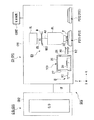
以下、本発明の露光装置及びデバイス製造方法について図面を参照しながら説明する。図1は本発明の露光装置を備えたデバイス製造システムの一実施形態を示す図であって側方から見た概略構成図、図2は図1を上方から見た図である。
First Embodiment Hereinafter, an exposure apparatus and a device manufacturing method of the present invention will be described with reference to the drawings. FIG. 1 is a view showing one embodiment of a device manufacturing system provided with an exposure apparatus of the present invention, and is a schematic configuration view seen from the side, and FIG. 2 is a view seen from above.
図1、図2において、デバイス製造システムSYSは、露光装置EX−SYSと、コータ・デベロッパ装置C/D−SYSとを備えている。露光装置EX−SYSは、コータ・デベロッパ装置C/D−SYSとの接続部を形成するインターフェース部IFと、投影光学系PLと基板Pとの間を液体50で満たし、投影光学系PLと液体50とを介してパターンの像を基板P上に投影して基板Pを露光する露光装置本体EXと、インターフェース部IFと露光装置本体EXとの間で基板Pを搬送する搬送システムHと、搬送システムHの搬送経路の途中に設けられ、露光処理後の基板Pに付着した液体を除去する液体除去装置100と、露光装置EX−SYS全体の動作を統括制御する制御装置CONTとを備えている。コータ・デベロッパ装置C/D−SYSは、露光処理される前の基板Pの基材に対してフォトレジスト(感光剤)を塗布する塗布装置Cと、露光装置本体EXにおいて露光処理された後の基板Pを現像処理する現像装置(処理装置)Dとを備えている。露光装置本体EXはクリーン度が管理された第1チャンバ装置CH1内部に配置されている。一方、塗布装置C及び現像装置Dは第1チャンバ装置CH1とは別の第2チャンバ装置CH2内部に配置されている。そして、露光装置本体EXを収容する第1チャンバ装置CH1と、塗布装置C及び現像装置Dを収容する第2チャンバ装置CH2とは、インターフェース部IFを介して接続されている。ここで、以下の説明において、第2チャンバ装置CH2内部に収容されている塗布装置C及び現像装置Dを合わせて「コータ・デベロッパ本体C/D」と適宜称する。
1 and 2, the device manufacturing system SYS includes an exposure apparatus EX-SYS and a coater / developer apparatus C / D-SYS. The exposure apparatus EX-SYS is filled with a liquid 50 between an interface unit IF that forms a connection with the coater / developer apparatus C / D-SYS, and between the projection optical system PL and the substrate P, and the projection optical system PL and the liquid 50, an exposure apparatus main body EX that projects an image of a pattern onto the substrate P through 50, and exposes the substrate P; a transport system H that transports the substrate P between the interface unit IF and the exposure apparatus main body EX; A
図1に示すように、露光装置本体EXは、露光光ELでマスクステージMSTに支持されているマスクMを照明する照明光学系ILと、露光光ELで照明されたマスクMのパターンの像を基板P上に投影する投影光学系PLと、基板Pを支持する基板ステージPSTとを備えている。本実施形態における露光装置本体EXは2つの基板ステージPST1,PST2を有する所謂ツインステージシステムを採用している。ツインステージシステムの具体的な構成としては、特開平10−163099号公報、特開平10−214783号公報、特表2000−505958号公報、米国特許6,341,007号、6,400,441号、6,549,269号及び6,590,634号等の文献に開示されており、それらを参照することができる。それらの米国特許を、本国際出願で指定または選択された国の法令で許容される限りにおいて、援用して本文の記載の一部とする。本発明では、上記文献に開示されているツインステージシステムを採用することができる。また、本実施形態における露光装置本体EXは、マスクMと基板Pとを走査方向における互いに異なる向き(逆方向)に同期移動しつつマスクMに形成されたパターンを基板Pに露光する走査型露光装置(所謂スキャニングステッパ)である。以下の説明において、水平面内においてマスクMと基板Pとの同期移動方向(走査方向)をX軸方向、水平面内においてX軸方向と直交する方向をY軸方向(非走査方向)、X軸及びY軸方向に垂直で投影光学系PLの光軸AXと一致する方向をZ軸方向とする。また、X軸、Y軸、及びZ軸まわり方向をそれぞれ、θX、θY、及びθZ方向とする。なお、ここでいう「基板」は半導体ウエハ上にレジストを塗布したものを含み、「マスク」は基板上に縮小投影されるデバイスパターンを形成されたレチクルを含む。 As shown in FIG. 1, the exposure apparatus main body EX has an illumination optical system IL that illuminates the mask M supported by the mask stage MST with the exposure light EL, and an image of the pattern of the mask M that is illuminated with the exposure light EL. A projection optical system PL that projects onto the substrate P and a substrate stage PST that supports the substrate P are provided. The exposure apparatus main body EX in the present embodiment employs a so-called twin stage system having two substrate stages PST1 and PST2. Specific configurations of the twin stage system are disclosed in JP 10-163099 A, JP 10-214783 A, JP 2000-505958 A, US Pat. Nos. 6,341,007, 6,400,441. 6,549,269 and 6,590,634, and the like, and can be referred to. These US patents are incorporated herein by reference to the extent permitted by national legislation designated or selected in this international application. In the present invention, the twin stage system disclosed in the above document can be employed. Further, the exposure apparatus main body EX in the present embodiment exposes the pattern formed on the mask M to the substrate P while synchronously moving the mask M and the substrate P in mutually different directions (reverse directions) in the scanning direction. An apparatus (so-called scanning stepper). In the following description, the synchronous movement direction (scanning direction) of the mask M and the substrate P in the horizontal plane is the X-axis direction, the direction orthogonal to the X-axis direction in the horizontal plane is the Y-axis direction (non-scanning direction), the X-axis, and A direction perpendicular to the Y-axis direction and coincident with the optical axis AX of the projection optical system PL is defined as a Z-axis direction. Further, the directions around the X axis, the Y axis, and the Z axis are defined as θX, θY, and θZ directions, respectively. Here, the “substrate” includes a semiconductor wafer coated with a resist, and the “mask” includes a reticle on which a device pattern to be reduced and projected on the substrate is formed.
搬送システムHは、露光処理される前の基板Pを基板ステージPSTに搬入(ロード)する第1搬送装置H1と、露光処理された後の基板Pを基板ステージPSTから搬出(アンロード)し、液体除去装置100まで搬送する第2搬送装置H2と、液体除去装置100とインターフェース部IFとの間で基板Pを搬送する第3搬送装置H3とを備えている。第1、第2、第3搬送装置H1、H2、H3は第1チャンバ装置CH1内部に設けられている。コータ・デベロッパ本体C/D(塗布装置C)でフォトレジストの塗布処理を施された基板Pはインターフェース部IFを介して第3搬送装置H3に渡される。ここで、第1、第2チャンバ装置CH1、CH2それぞれのインターフェース部IFと対面する部分には開口部及びこの開口部を開閉するシャッタが設けられている。基板Pのインターフェース部IFに対する搬送動作中にはシャッタが開放される。第3搬送装置H3は露光処理される前の基板Pを液体除去装置100を介して第1搬送装置H1に渡す。なお、第3搬送装置H3から第1搬送装置H1に基板Pを渡す際、液体除去装置100を介さずに、不図示の別の搬送装置や中継装置を介して第1搬送装置H1に渡してもよい。第1搬送装置H1は渡された基板Pを露光装置本体EXの基板ステージPSTにロードする。露光処理された後の基板Pは第2搬送装置H2により基板ステージPSTからアンロードされる。第2搬送装置H2はアンロードした基板Pを液体除去装置100を介して第3搬送装置H3に渡す。第3搬送装置H3で搬送された基板Pはインターフェース部IFを介してコータ・デベロッパ本体C/D(現像装置D)に運ばれる。現像装置Dは渡された基板Pに対して現像処理を施す。
The transport system H carries out (loads) the substrate P before exposure processing to the substrate stage PST, and unloads the substrate P after exposure processing from the substrate stage PST. A second transport device H2 for transporting to the
なお、露光処理される前の濡れていない基板Pを基板ステージPSTに搬入する第1搬送装置H1と、露光処理された後の濡れている可能性のある基板Pを基板ステージPSTから搬出する第2搬送装置H2とを使い分けているので、第1搬送装置(搬送部材)H1に液体が付着することがなく、第1搬送装置H1で搬送される基板Pの裏面などへの液体の付着を防止することができる。 Note that the first transfer device H1 that carries a substrate P that has not been wet before exposure processing into the substrate stage PST, and a first device that carries out the substrate P that may be wet after exposure processing from the substrate stage PST. Since the two transport devices H2 are properly used, the liquid does not adhere to the first transport device (transport member) H1 and prevents the liquid from adhering to the back surface of the substrate P transported by the first transport device H1. can do.
図3は、露光装置本体EXの概略構成図である。照明光学系ILは、マスクステージMSTに支持されているマスクMを露光光ELで照明するものであり、露光用光源、露光用光源から射出された光束の照度を均一化するオプティカルインテグレータ、オプティカルインテグレータからの露光光ELを集光するコンデンサレンズ、リレーレンズ系、露光光ELによるマスクM上の照明領域をスリット状に設定する可変視野絞り等を有している。マスクM上の所定の照明領域は照明光学系ILにより均一な照度分布の露光光ELで照明される。照明光学系ILから射出される露光光ELとしては、例えば水銀ランプから射出される紫外域の輝線(g線、h線、i線)及びKrFエキシマレーザ光(波長248nm)等の遠紫外光(DUV光)や、ArFエキシマレーザ光(波長193nm)及びF2レーザ光(波長157nm)等の真空紫外光(VUV光)などが用いられる。本実施形態では、ArFエキシマレーザ光を用いる。 FIG. 3 is a schematic block diagram of the exposure apparatus main body EX. The illumination optical system IL illuminates the mask M supported by the mask stage MST with the exposure light EL, and the exposure light source, and an optical integrator and an optical integrator for uniformizing the illuminance of the light beam emitted from the exposure light source A condenser lens that collects the exposure light EL from the light source, a relay lens system, a variable field stop that sets the illumination area on the mask M by the exposure light EL in a slit shape, and the like. A predetermined illumination area on the mask M is illuminated with the exposure light EL having a uniform illuminance distribution by the illumination optical system IL. As the exposure light EL emitted from the illumination optical system IL, for example, far ultraviolet light (g-line, h-line, i-line) and KrF excimer laser light (wavelength 248 nm) emitted from a mercury lamp (e.g. DUV light), vacuum ultraviolet light (VUV light) such as ArF excimer laser light (wavelength 193 nm) and F 2 laser light (wavelength 157 nm), or the like is used. In this embodiment, ArF excimer laser light is used.
マスクステージMSTは、マスクMを支持するものであって、投影光学系PLの光軸AXに垂直な平面内、すなわちXY平面内で2次元移動可能及びθZ方向に微小回転可能である。マスクステージMSTはリニアモータ等のマスクステージ駆動装置MSTDにより駆動される。マスクステージ駆動装置MSTDは制御装置CONTにより制御される。マスクステージMST上のマスクMの2次元方向の位置、及び回転角はレーザ干渉計によりリアルタイムで計測され、計測結果は制御装置CONTに出力される。制御装置CONTはレーザ干渉計の計測結果に基づいてマスクステージ駆動装置MSTDを駆動することでマスクステージMSTに支持されているマスクMの位置決めを行う。 The mask stage MST supports the mask M, and can move two-dimensionally in a plane perpendicular to the optical axis AX of the projection optical system PL, that is, in the XY plane, and can be slightly rotated in the θZ direction. The mask stage MST is driven by a mask stage driving device MSTD such as a linear motor. The mask stage driving device MSTD is controlled by the control device CONT. The two-dimensional position and rotation angle of the mask M on the mask stage MST are measured in real time by the laser interferometer, and the measurement result is output to the control device CONT. The control device CONT drives the mask stage driving device MSTD based on the measurement result of the laser interferometer, thereby positioning the mask M supported on the mask stage MST.
投影光学系PLは、マスクMのパターンを所定の投影倍率βで基板Pに投影露光するものであって、複数の光学素子(レンズ)で構成されており、これら光学素子は金属部材としての鏡筒PKで支持されている。本実施形態において、投影光学系PLは、投影倍率βが例えば1/4あるいは1/5の縮小系である。なお、投影光学系PLは等倍系及び拡大系のいずれでもよいし、ミラーを使って構成してもよい。また、本実施形態の投影光学系PLの先端側(基板P側)には、光学素子(レンズ)60が鏡筒PKより露出している。この光学素子60は鏡筒PKに対して着脱(交換)可能に設けられている。
The projection optical system PL projects and exposes the pattern of the mask M onto the substrate P at a predetermined projection magnification β, and is composed of a plurality of optical elements (lenses). These optical elements are mirrors as metal members. It is supported by the cylinder PK. In the present embodiment, the projection optical system PL is a reduction system having a projection magnification β of, for example, 1/4 or 1/5. Note that the projection optical system PL may be either an equal magnification system or an enlargement system, or may be configured using a mirror. Further, the optical element (lens) 60 is exposed from the lens barrel PK on the front end side (substrate P side) of the projection optical system PL of the present embodiment. This
基板ステージPSTは、基板Pを支持するものであって、基板Pを基板ホルダを介して保持するZステージ51と、Zステージ51を支持するXYステージ52と、XYステージ52を支持するベース53とを備えている。基板ステージPSTはリニアモータ等の基板ステージ駆動装置PSTDにより駆動される。基板ステージ駆動装置PSTDは制御装置CONTにより制御される。Zステージ51を駆動することにより、Zステージ51に保持されている基板PのZ軸方向における位置(フォーカス位置)、及びθX、θY方向における位置が制御される。また、XYステージ52を駆動することにより、基板PのXY方向における位置(投影光学系PLの像面と実質的に平行な方向の位置)が制御される。すなわち、Zステージ51は、基板Pのフォーカス位置及び傾斜角を制御して基板Pの表面をオートフォーカス方式、及びオートレベリング方式で投影光学系PLの像面に合わせ込み、XYステージ52は基板PのX軸方向及びY軸方向における位置決めを行う。なお、ZステージとXYステージとを一体的に設けてよいことは言うまでもない。
The substrate stage PST supports the substrate P, and includes a
基板ステージPST(Zステージ51)上には移動鏡54が設けられている。また、移動鏡54に対向する位置にはレーザ干渉計55が設けられている。基板ステージPST上の基板Pの2次元方向の位置、及び回転角はレーザ干渉計55によりリアルタイムで計測され、計測結果は制御装置CONTに出力される。制御装置CONTはレーザ干渉計55の計測結果に基づいて基板ステージ駆動装置PSTDを駆動することで基板ステージPSTに支持されている基板Pの位置決めを行う。
A
本実施形態では、露光波長を実質的に短くして解像度を向上するとともに、焦点深度を実質的に広くするために、液浸法を適用する。そのため、少なくともマスクMのパターンの像を基板P上に転写している間は、基板Pの表面と投影光学系PLの基板P側の光学素子(レンズ)60の先端面(下面)7との間に所定の液体50が満たされる。上述したように、投影光学系PLの先端側にはレンズ60が露出しており、液体50はレンズ60のみに接触するように構成されている。これにより、金属からなる鏡筒PKの腐蝕等が防止されている。本実施形態において、液体50には純水が用いられる。純水は、ArFエキシマレーザ光のみならず、露光光ELを例えば水銀ランプから射出される紫外域の輝線(g線、h線、i線)及びKrFエキシマレーザ光(波長248nm)等の遠紫外光(DUV光)とした場合、この露光光ELを透過可能である。
In the present embodiment, the immersion method is applied to improve the resolution by substantially shortening the exposure wavelength and to substantially increase the depth of focus. Therefore, at least during the transfer of the pattern image of the mask M onto the substrate P, the surface of the substrate P and the tip surface (lower surface) 7 of the optical element (lens) 60 on the substrate P side of the projection optical system PL. In the meantime, a
露光装置本体EXは、投影光学系PLの先端面(レンズ60の先端面)7と基板Pとの間の空間56に所定の液体50を供給する液体供給装置1と、空間56の液体50を回収する液体回収装置2とを備えている。液体供給装置1は、投影光学系PLと基板Pとの間の少なくとも一部を液体50で満たすためのものであって、液体50を収容するタンク、加圧ポンプなどを備えている。液体供給装置1には供給管3の一端部が接続され、供給管3の他端部には供給ノズル4が接続されている。液体供給装置1は供給管3及び供給ノズル4を介して空間56に液体50を供給する。
The exposure apparatus main body EX includes a
液体回収装置2は、吸引ポンプ、回収した液体50を収容するタンクなどを備えている。液体回収装置2には回収管6の一端部が接続され、回収管6の他端部には回収ノズル5が接続されている。液体回収装置2は回収ノズル5及び回収管6を介して空間56の液体50を回収する。空間56に液体50を満たす際、制御装置CONTは液体供給装置1を駆動し、供給管3及び供給ノズル4を介して空間56に対して単位時間当たり所定量の液体50を供給するとともに、液体回収装置2を駆動し、回収ノズル5及び回収管6を介して単位時間当たり所定量の液体50を空間56より回収する。これにより、投影光学系PLの先端面7と基板Pとの間の空間56に液体50が配置される。
The
投影光学系PLの最下端のレンズ60は、先端部60Aが走査方向に必要な部分だけを残してY軸方向(非走査方向)に細長い矩形状に形成されている。走査露光時には、先端部60Aの直下の矩形の投影領域にマスクMの一部のパターン像が投影され、投影光学系PLに対して、マスクMが−X方向(又は+X方向)に速度Vで移動するのに同期して、XYステージ52を介して基板Pが+X方向(又は−X方向)に速度β・V(βは投影倍率)で移動する。そして、1つのショット領域への露光終了後に、基板Pのステッピングによって次のショット領域が走査開始位置に移動し、以下、ステップ・アンド・スキャン方式で各ショット領域に対する露光処理が順次行われる。本実施形態では、基板Pの移動方向と平行に基板の移動方向と同一方向に液体50を流すように設定されている。
The
図4は、投影光学系PLのレンズ60の先端部60Aと、液体50をX軸方向に供給する供給ノズル4(4A〜4C)と、液体50を回収する回収ノズル5(5A、5B)との位置関係を示す図である。図4において、レンズ60の先端部60Aの形状はY軸方向に細長い矩形状となっており、投影光学系PLのレンズ60の先端部60AをX軸方向に挟むように、+X方向側に3つの供給ノズル4A〜4Cが配置され、−X方向側に2つの回収ノズル5A、5Bが配置されている。そして、供給ノズル4A〜4Cは供給管3を介して液体供給装置1に接続され、回収ノズル5A、5Bは回収管4を介して液体回収装置2に接続されている。また、供給ノズル4A〜4Cと回収ノズル5A、5Bとを先端部60Aの中心に対してほぼ180°回転した位置に、供給ノズル8A〜8Cと、回収ノズル9A、9Bとが配置されている。供給ノズル4A〜4Cと回収ノズル9A、9BとはY軸方向に交互に配列され、供給ノズル8A〜8Cと回収ノズル5A、5BとはY軸方向に交互に配列され、供給ノズル8A〜8Cは供給管10を介して液体供給装置1に接続され、回収ノズル9A、9Bは回収管11を介して液体回収装置2に接続されている。なおノズルからの液体供給は、投影光学系PLと基板Pとの間に気体部分が生じないように行う必要がある。
FIG. 4 shows the
露光装置本体EXにおいて、矢印Xa(図4参照)で示す走査方向(−X方向)に基板Pを移動させて走査露光を行う場合には、供給管3、供給ノズル4A〜4C、回収管4、及び回収ノズル5A、5Bを用いて、液体供給装置1及び液体回収装置2により液体50の供給及び回収が行われる。すなわち、基板Pが−X方向に移動する際には、供給管3及び供給ノズル4(4A〜4C)を介して液体供給装置1から液体50が投影光学系PLと基板Pとの間に供給されるとともに、回収ノズル5(5A、5B)、及び回収管6を介して液体50が液体回収装置2に回収され、レンズ60と基板Pとの間を満たすように−X方向に液体50が流れる。一方、矢印Xbで示す走査方向(+X方向)に基板Pを移動させて走査露光を行う場合には、供給管10、供給ノズル8A〜8C、回収管11、及び回収ノズル9A、9Bを用いて、液体供給装置1及び液体回収装置2により液体50の供給及び回収が行われる。すなわち、基板Pが+X方向に移動する際には、供給管10及び供給ノズル8(8A〜8C)を介して液体供給装置1から液体50が投影光学系PLと基板Pとの間に供給されるとともに、回収ノズル9(9A、9B)、及び回収管11を介して液体50が液体回収装置2に回収され、レンズ60と基板Pとの間を満たすように+X方向に液体50が流れる。このように、制御装置CONTは、液体供給装置1及び液体回収装置2を用いて、基板Pの移動方向に沿って液体50を流す。この場合、例えば液体供給装置1から供給ノズル4を介して供給される液体50は基板Pの−X方向への移動に伴って空間56に引き込まれるようにして流れるので、液体供給装置1の供給エネルギーが小さくでも液体50を空間56に容易に供給できる。そして、走査方向に応じて液体50を流す方向を切り替えることにより、+X方向、又は−X方向のどちらの方向に基板Pを走査する場合にも、レンズ60の先端面7と基板Pとの間を液体50で満たすことができ、高い解像度及び広い焦点深度を得ることができる。
In the exposure apparatus main body EX, when scanning exposure is performed by moving the substrate P in the scanning direction (−X direction) indicated by the arrow Xa (see FIG. 4), the supply tube 3, the supply nozzles 4 </ b> A to 4 </ b> C, and the recovery tube 4. The
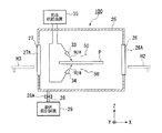
次に、図5を参照しながら第1実施形態の露光装置に用いられる液体除去装置100について説明する。液体除去装置100は搬送システムHの搬送経路の途中に設けられ、液浸法により露光処理された後の基板Pに付着している液体50を除去するものである。本実施形態において、液体除去装置100は第2搬送装置H2と第3搬送装置H3との間に設けられている。液体除去装置100は、ステージ装置20と、ステージ装置20に設けられ、基板Pの下面中央部を保持するホルダ部21と、基板Pを保持したホルダ部21を回転する回転機構22とを備えている。ホルダ部21の上面にはバキューム装置の一部を構成する真空吸着孔が設けられており、ホルダ部21は基板Pの下面中央部を吸着保持する。回転機構22はステージ装置20内部に設けられたモータにより構成されており、ホルダ部21に接続された軸部23を回転することでホルダ部21を回転する。そして、ステージ装置20、ホルダ部21、及び回転機構22はカバー機構であるチャンバ25内部に設けられており、チャンバ25には流路28を介して液体吸引装置29が設けられている。流路28にはバルブ28Aが設けられている。
Next, the
ホルダ部21は軸部23とともにステージ装置20の上面に対して昇降可能に設けられている。基板Pを保持したホルダ部21がステージ装置20に対して上昇したとき、基板Pはステージ装置20より離れ、回転機構22の駆動により回転可能となる。一方、ホルダ部21が下降しているときは基板Pはステージ装置20の上面に設けられている第2ホルダ部24により保持される。
The
チャンバ25は、第2搬送装置H2側に形成された第1開口部26と、第3搬送装置H3側に形成された第2開口部27とを備えている。第1開口部26には、この第1開口部26を開閉する第1シャッタ26Aが設けられ、第2開口部27には、この第2開口部27を開閉する第2シャッタ27Aが設けられている。第1、第2シャッタ26A、27Aの開閉動作は制御装置CONTにより制御される。第1シャッタ26Aが開放されると、第2搬送装置H2は第1開口部26を介して液体除去装置100のステージ装置20にアクセス可能となる。すなわち、第2搬送装置H2は第1開口部26を介して液体除去装置100のステージ装置20に対して基板Pを搬送(搬入)可能である。第3搬送装置H3は第2開口部27を介して液体除去装置100のステージ装置20にアクセス可能となる。すなわち、第3搬送装置H3は第2開口部27を介して液体除去装置100のステージ装置20に対して基板Pを搬送(搬出)可能である。一方、第1、第2シャッタ26A、27Aを閉じることによりチャンバ25内部は密閉される。
The
次に、上述した露光装置本体EX及び液体除去装置100を備えたデバイス製造システムSYSの動作について、図1及び2を用いて説明する。
Next, the operation of the device manufacturing system SYS including the exposure apparatus main body EX and the
露光装置本体EXにおいて、基板ステージPST1に保持された基板Pは、液浸法を用いて露光され、それと並行して、基板ステージPST2に保持された基板Pに対して、アライメントマークの検出や表面情報(AF(オートフォーカス)/AL(オートレベリング)情報)の計測が行われる。図1は基板ステージPST1が露光装置本体(露光ステーション)EXにおいて露光動作を行い、基板ステージPST2が計測ステーションにおいて計測動作を行っている様子を示している。露光装置本体では、液体供給装置1の液体供給と液体回収装置2の液体回収とが行われ、投影光学系PLの像面側の露光光の光路が液体50で満たされている。基板ステージPST1に保持された基板Pの露光処理が完了すると、液体供給装置1の液体供給を停止し、液体回収装置2により液体回収を行う。液体回収装置2による液体回収が終了すると、基板ステージPST1が露光装置本体EXから退避するとともに、各種計測を終えた基板ステージPST2が露光装置本体(露光ステーション)EXに投入される。基板ステージPST1上で露光処理を終えた基板Pは、基板ステージPST1より第2搬送装置H2にアンロードされる。露光処理後の基板Pのアンロードを終えた基板ステージPST1は、未露光の基板Pを第1搬送装置H1から受け取り、計測ステーションでの各種計測を開始する。第2搬送装置H2にアンロードされた基板Pには液体回収装置2で回収しきれなかった液体50がわずかに付着しており、第2搬送装置H2によって液体除去装置100に搬送される。こうして、基板ステージPST2に保持された基板Pの露光処理、及び基板ステージPST1に保持された未露光の基板Pの各種計測と並行して、直前に露光処理を完了した基板Pに残留した液体の除去が液体除去装置100で行われる。
In the exposure apparatus main body EX, the substrate P held on the substrate stage PST1 is exposed using the liquid immersion method, and in parallel with this, the detection of the alignment mark and the surface of the substrate P held on the substrate stage PST2 are performed. Information (AF (autofocus) / AL (auto leveling) information) is measured. FIG. 1 shows a state in which the substrate stage PST1 performs an exposure operation in the exposure apparatus main body (exposure station) EX, and the substrate stage PST2 performs a measurement operation in the measurement station. In the exposure apparatus main body, the liquid supply of the
なお、基板ステージPST2に保持された基板P上に液体供給装置1から液体の供給を開始する際には、基板ステージPST1では実質的な計測動作を行わずに、基板ステージPST1の移動のみ、あるいは単に基板ステージPST1を停止させておくとよい。このようにすることで、基板ステージPST2上に液体供給装置1から液体の供給を開始する際に生じる振動が計測ステーションにおける基板ステージPST1の計測動作に影響を及ぼすことを防止できる。また、基板ステージPST2上への液体の供給を停止するときに、計測ステーションでの基板ステージPST1の計測動作が完了していない場合には、液体供給を停止するときに、基板ステージPST1では実質的な計測動作を行わずに、基板ステージPST1の移動のみ、あるいは単に基板ステージPST1を停止させておくようにしてもよい。
Note that when the supply of the liquid from the
制御装置CONTは第2搬送装置H2の液体除去装置100に対する接近に伴って第1シャッタ26Aを開放する(図5参照)。このとき、第2シャッタ27Aは閉じられている。第2搬送装置H2は、第1開口部26を介して基板Pを液体除去装置100のステージ装置20に渡す。このとき、ホルダ部21は下降しており、基板Pはステージ装置20上のホルダ部21及び第2ホルダ部24に保持される。
The control device CONT opens the
第2搬送装置H2はステージ装置20に基板Pを渡したら、第1開口部26を介してチャンバ25より退避する。第2搬送装置H2がチャンバ25より退避したら制御装置CONTは第1シャッタ26Aを閉じる。これにより、チャンバ25内部は密閉される。チャンバ25内部が密閉されたら、制御装置CONTはホルダ部21を上昇する。ホルダ部21の上昇とともに、このホルダ部21に吸着保持されている基板Pもステージ装置20に対して上昇する。そして、制御装置CONTは回転機構22を駆動し、ホルダ部21を基板PとともにθZ方向に回転する。回転機構22が基板Pを回転することにより、基板Pの上下両面に付着している液体50は遠心力の作用により基板Pから飛ばされる。これにより、基板Pに付着している液体50が基板Pより除去される。ここで、基板Pはカバー機構としてのチャンバ25内部に配置されているため、基板Pから飛ばされた液体50は周囲に飛散しない。
When the second transfer device H2 passes the substrate P to the
基板Pから飛ばされた液体50はチャンバ25に接続されている液体吸引装置29により回収される。液体吸引装置29はチャンバ25内部の気体を飛散した液体50とともに吸引することで、基板Pから飛ばされた液体50を回収する。ここで、液体吸引装置29は、チャンバ25内部の気体及び飛散した液体50の吸引動作を継続的に行う。これにより、チャンバ25の内壁や底などチャンバ25内部に液体50が留まらないので、チャンバ25内部の湿度が大きく変動することはない。また、シャッタ26A、27Aを開放したときにも、チャンバ25内の湿った気体がチャンバ25の外へ流れ出ることもない。
The liquid 50 ejected from the substrate P is collected by a
基板Pを所定時間(あるいは所定回転数)回転したら、制御装置CONTは回転機構22の駆動を停止し、基板Pをホルダ部21とともに下降する。次いで、制御装置CONTは、第2シャッタ27Aを開放する。第2シャッタ27Aが開放されたら、第3搬送装置(第2搬送部材)H3が第2開口部27を介してステージ装置20にアクセスし、ステージ装置20上の液体50を除去された基板Pを保持する。液体除去装置100により液体50を除去された基板Pを保持した第3搬送装置H3は、チャンバ25内部より基板Pを第2開口部27を介して搬出する。
When the substrate P is rotated for a predetermined time (or a predetermined number of rotations), the control device CONT stops driving the
図1に示すように、液体除去装置100により液体50が除去された基板Pは、インターフェース部IFを介してコータ・デベロッパ本体C/Dに運ばれる。コータ・デベロッパ本体C/D(現像装置D)は渡された基板Pに対して現像処理を施す。このように、本実施形態の露光装置EX−SYSは、インターフェース部IFを介して基板Pがコータ・デベロッパ装置CD−SYSに搬出される前に、液体除去装置100により基板Pに付着した液体50を除去する。
As shown in FIG. 1, the substrate P from which the liquid 50 has been removed by the
以上説明したように、露光装置本体EXにおいて露光処理が施された基板Pをコータ・デベロッパ装置C/D−SYS(現像装置D)に搬送する前に、液体除去装置100で基板Pに付着した液体50を除去するようにしたので、液体50の現像処理に対する影響を除くことができる。また、液体除去装置100によって基板Pに付着した液体50を除去することにより、基板Pの搬送中に基板Pから液体が落下し、第1チャンバ装置CH1内部の湿度変化(環境変化)をもたらしたり、搬送経路上の各装置や部材を錆びさせるなどの不都合の発生を抑えることができる。
As described above, the substrate P subjected to the exposure process in the exposure apparatus main body EX is attached to the substrate P by the
また、液体50が付着している基板Pを第2搬送装置H2で搬送し、液体50が除去された基板Pを第2搬送装置H2とは別の第3搬送装置H3で搬送するようにしたので、第3搬送装置H3は液体50に晒されない。したがって、第3搬送装置H3で搬送される基板Pには液体50が付着せず、また、第3搬送装置H3の搬送経路上における液体50の飛散を確実に防止できる。 Further, the substrate P on which the liquid 50 is adhered is transported by the second transport device H2, and the substrate P from which the liquid 50 has been removed is transported by a third transport device H3 different from the second transport device H2. Therefore, the third transport device H3 is not exposed to the liquid 50. Therefore, the liquid 50 does not adhere to the substrate P transported by the third transport apparatus H3, and the scattering of the liquid 50 on the transport path of the third transport apparatus H3 can be reliably prevented.
また、液体除去装置100を搬送システムHの搬送経路の途中に設けたので、露光装置本体EXでの露光処理と、液体除去装置100での液体除去処理とを同時に行うことができる。したがって、スループットを低下させることなく各処理を実行することができる。そして、液体除去処理をチャンバ25内部で行うようにしたので、周囲に液体50が飛散するのを防止できる。
Further, since the
なお、本実施形態では、露光処理後の基板Pを処理装置としてのコータ・デベロッパ装置C/D−SYSに搬送する際、接続部としてのインターフェース部IFを介して搬送するように説明したが、例えばインターフェース部IFがコータ・デベロッパ装置C/D−SYSに備えられている場合や、コータ・デベロッパ装置C/D−SYSがインターフェース部IFを介さずに直接露光装置EX−SYSに接続されている場合、あるいは、処理装置が基板収納装置であってインターフェース部IFを介さないで露光処理後の基板Pを基板収納装置に搬送する場合には、第1チャンバ装置CH1の開口部が露光装置EX−SYSの接続部となる。 In the present embodiment, the substrate P after the exposure processing is transported to the coater / developer apparatus C / D-SYS as a processing apparatus. However, the substrate P is transported via the interface section IF as a connection section. For example, when the interface unit IF is provided in the coater / developer apparatus C / D-SYS, or the coater / developer apparatus C / D-SYS is directly connected to the exposure apparatus EX-SYS without passing through the interface unit IF. In the case where the processing apparatus is a substrate storage apparatus and the substrate P after the exposure processing is transported to the substrate storage apparatus without passing through the interface unit IF, the opening of the first chamber apparatus CH1 is exposed to the exposure apparatus EX−. It becomes a connection part of SYS.
上述したように、本実施形態における液体50は純水により構成されている。純水は、半導体製造工場等で容易に大量に入手できるとともに、基板P上のフォトレジストや光学素子(レンズ)等に対する悪影響がない利点がある。また、純水は環境に対する悪影響がないとともに、不純物の含有量が極めて低いため、基板Pの表面、及び投影光学系PLの先端面に設けられている光学素子の表面を洗浄する作用も期待できる。 As described above, the liquid 50 in the present embodiment is composed of pure water. Pure water has an advantage that it can be easily obtained in large quantities at a semiconductor manufacturing factory or the like and has no adverse effect on the photoresist, optical element (lens), etc. on the substrate P. In addition, pure water has no adverse effects on the environment, and since the impurity content is extremely low, it can be expected to clean the surface of the substrate P and the surface of the optical element provided on the front end surface of the projection optical system PL. .
そして、波長が193nm程度の露光光ELに対する純水(水)の屈折率nはほぼ1.44〜1.47程度と言われており、露光光ELの光源としてArFエキシマレーザ光(波長193nm)を用いた場合、基板P上では1/n、すなわち約131〜134nm程度に短波長化されて高い解像度が得られる。更に、焦点深度は空気中に比べて約n倍、すなわち約1.44〜1.47倍程度に拡大されるため、空気中で使用する場合と同程度の焦点深度が確保できればよい場合には、投影光学系PLの開口数をより増加させることができ、この点でも解像度が向上する。 The refractive index n of pure water (water) with respect to the exposure light EL having a wavelength of about 193 nm is said to be about 1.44 to 1.47, and ArF excimer laser light (wavelength 193 nm) is used as the light source of the exposure light EL. Is used, the wavelength is shortened to 1 / n, that is, about 131 to 134 nm on the substrate P, and a high resolution can be obtained. Furthermore, since the depth of focus is expanded to about n times, that is, about 1.44 to 1.47 times compared with that in the air, if it is sufficient to ensure the same depth of focus as that used in the air. The numerical aperture of the projection optical system PL can be further increased, and the resolution is improved in this respect as well.
本実施形態では、投影光学系PLの先端にレンズ60が取り付けられているが、投影光学系PLの先端に取り付ける光学素子としては、投影光学系PLの光学特性、例えば収差(球面収差、コマ収差等)の調整に用いる光学プレートであってもよい。あるいは露光光ELを透過可能な平行平面板であってもよい。液体50と接触する光学素子を、レンズより安価な平行平面板とすることにより、露光装置本体EXの運搬、組立、調整時等において投影光学系PLの透過率、基板P上での露光光ELの照度、及び照度分布の均一性を低下させる物質(例えばシリコン系有機物等)がその平行平面板に付着しても、液体50を供給する直前にその平行平面板を交換するだけでよく、液体50と接触する光学素子をレンズとする場合に比べてその交換コストが低くなるという利点がある。すなわち、露光光ELの照射によりレジストから発生する飛散粒子、または液体50中の不純物の付着などに起因して液体50に接触する光学素子の表面が汚れるため、その光学素子を定期的に交換する必要があるが、この光学素子を安価な平行平面板とすることにより、レンズに比べて交換部品のコストが低く、且つ交換に要する時間を短くすることができ、メンテナンスコスト(ランニングコスト)の上昇やスループットの低下を抑えることができる。
In the present embodiment, the
なお、液体50の流れによって生じる投影光学系PLの先端の光学素子と基板Pとの間の圧力が大きい場合には、その光学素子を交換可能とするのではなく、その圧力によって光学素子が動かないように堅固に固定してもよい。 When the pressure between the optical element at the tip of the projection optical system PL generated by the flow of the liquid 50 and the substrate P is large, the optical element is not exchangeable but the optical element is moved by the pressure. It may be fixed firmly so that there is no.
なお、本実施形態では、投影光学系PLと基板P表面との間は液体50で満たされている構成であるが、例えば基板Pの表面に平行平面板からなるカバーガラスを取り付けた状態で液体50を満たす構成であってもよい。 In the present embodiment, the space between the projection optical system PL and the surface of the substrate P is filled with the liquid 50. For example, the liquid is obtained with a cover glass made of a plane-parallel plate attached to the surface of the substrate P. 50 may be sufficient.
なお、上記実施形態において、上述したノズルの形状は特に限定されるものでなく、例えば先端部60Aの長辺について2対のノズルで液体50の供給又は回収を行うようにしてもよい。なお、この場合には、+X方向、又は−X方向のどちらの方向からも液体50の供給及び回収を行うことができるようにするため、供給ノズルと回収ノズルと上下に並べて配置してもよい。
In the above embodiment, the shape of the nozzle described above is not particularly limited. For example, the liquid 50 may be supplied or recovered with two pairs of nozzles on the long side of the
第2実施形態
次に、本発明の第2実施形態の露光装置に用いられる液体除去装置100のについて図6を参照しながら説明する。ここで、以下の説明において、液体除去装置100以外については、第1実施形態と同一又は同等であるのでその説明を簡略もしくは省略する。
Second Embodiment Next, a
図6において、液体除去装置100は、基板Pに付着した液体50の除去を行うときに液体50が飛散しないように基板Pの周囲を覆うカバー機構の一部を構成するカバー部30を備えている。本実施形態における液体除去装置100はチャンバ25を有していない。カバー部30は平面視ほぼ円環状に形成されており、その円環内部にポケット部30Aを備えている。カバー部30のポケット部30Aには液体吸引装置29が接続されている。また、カバー部30はステージ装置20に形成された凹部31に配置可能となっており、昇降機構32によりステージ装置20に対して昇降可能(出没可能)に設けられている。液体除去処理を行う際には、ホルダ部21の上昇とともにカバー部30も上昇される。カバー部30は基板Pの周囲を覆うように設けられているため、基板Pの回転により飛ばされた液体50はカバー部30のポケット部30Aに回収される。ポケット部30Aに回収された液体50は液体吸引装置29により回収される。
In FIG. 6, the
以上説明したように、カバー機構として、基板Pの周囲を覆うカバー部30を用いることもできる。これにより、第1実施形態で説明したチャンバ25に比べて簡易な構成で液体50の周囲への飛散を防止できる。
As described above, the
第3実施形態
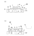
次に、図7を参照しながら第3実施形態の露光装置に用いられる液体除去装置100について説明する。本実施形態の特徴的部分は、液体除去装置100を構成する回転機構22及びカバー部30が、露光処理を行う露光装置本体EXの基板ステージPSTに設けられている点である。露光装置本体EXの構造は第1実施形態と同様であるので、その説明を省略する。
Third Embodiment Next, a
図7(a)において、基板ステージPSTは、基板Pを保持するホルダ部21及び第2ホルダ部24と、カバー部30を収容可能な凹部31とを備えている。そして、図7(a)に示すように、ホルダ部21及び第2ホルダ部24に保持されている基板Pに対して投影光学系PL及び液体50を介してパターンの像が転写される。基板Pに対する露光処理が終了したら、制御装置CONTは、図7(b)に示すように、投影光学系PLと基板Pとの間に対する液体供給装置1からの液体50の供給を停止するとともに、液体回収装置2により基板P上の液体50を回収する。その回収作業が完了すると、基板ステージPSTを投影光学系PLの直下から退避させる。次いで、制御装置CONTは、基板Pを保持するホルダ部21を上昇するとともにカバー部30を上昇し、回転機構22を駆動して基板Pを回転する。これにより、液体回収装置2で回収しきれずに基板Pに付着している液体50は基板Pから除去される。そして、基板Pに付着した液体50を除去したら、第2搬送装置H2が基板ステージPSTより基板Pを搬出する。
In FIG. 7A, the substrate stage PST includes a
以上説明したように、液体除去装置100を基板ステージPSTに設けることも可能である。そして、露光処理が行われる基板ステージPSTから基板Pを搬出する前に、基板Pに付着した液体を除去することで、基板Pの搬送中において基板Pから液体50が落下するといった不都合の発生を抑えることができる。また、本実施形態では、露光装置本体EXはツインステージシステムを採用しているので、第1の基板ステージPST1における露光処理と、第2の基板ステージPST2における液体除去処理とを同時に行うことができ、スループットを低下させることなく全体の処理を実行できる。
As described above, the
また、第3実施形態では、基板ステージPSTから露光処理後の基板Pを搬送する前に基板Pに付着した液体を除去するために基板Pを回転させる機構を採用しているが、液体を吹き飛ばすブロアを設けたり、液体回収装置2とは別に基板P上の残留液体を吸引する機構を設けてもよいし、これらを併用してもよい。
In the third embodiment, a mechanism for rotating the substrate P is used to remove the liquid adhering to the substrate P before transporting the substrate P after the exposure processing from the substrate stage PST, but the liquid is blown off. A blower may be provided, or a mechanism for sucking the residual liquid on the substrate P may be provided separately from the
第4実施形態
次に、図8を参照しながら第4実施形態の露光装置に用いる液体除去装置100について説明する。図8に示す液体除去装置100は、搬送システムHの搬送経路の途中であって、第2搬送装置H2と第3搬送装置H3との間に設けられ、チャンバ25を備えた構成である。露光装置本体EXの構造は第1実施形態と同様であるので、その説明を省略する。
Fourth Embodiment Next, a
図8において、液体除去装置100は、基板Pの表面(上面)に対して気体を吹き付けてこの基板Pの表面に付着している液体50を飛ばすことで除去する第1吹出部33と、基板Pの裏面(下面)に対して気体を吹き付けてこの基板Pの裏面に付着している液体50を飛ばすことで除去する第2吹出部34とを備えている。第1、第2吹出部33、34のそれぞれは流路を介して気体供給装置35に接続されている。流路には、基板Pに対して吹き付ける気体中の異物(ゴミやオイルミスト)を除去するフィルタが設けられている。そして、気体供給装置35は乾燥した気体を第1、第2吹出部33、34に供給する。本実施形態において、気体供給装置35は乾燥エアーを供給する。
In FIG. 8, the
図9は、図8のチャンバ25内部を上方から見た図である。図9に示すように、基板Pはその下面のY軸方向両端部を保持装置36により保持される(なお、図8には保持装置36は図示されていない)。保持装置36は第2搬送装置H2より基板Pを渡され、この渡された基板Pを保持する。また、保持装置36に保持されている基板Pは第3搬送装置H3に渡されるようになっている。第1吹出部33はY軸方向を長手方向とするノズル本体部33Aと、ノズル本体部33Aの長手方向に複数並んで設けられたノズル孔33Bとを備えている。気体供給装置35から供給された乾燥エアーは複数のノズル孔33Bのそれぞれから吹き出される。第2吹出部34も第1吹出部33と同等の構成を有しており、Y軸方向を長手方向とするノズル本体部と複数のノズル孔とを有している。
FIG. 9 is a view of the inside of the
保持装置36に保持された基板Pと第1、第2吹出部33、34とは相対移動可能に設けられている。本実施形態では、第1、第2吹出部33、34が保持装置36に保持された基板Pに対してX軸方向に走査移動するようになっている。なお、保持装置36に駆動装置を設け、第1、第2吹出部33、34に対して基板Pを移動するようにしてもよいし、第1、第2吹出部33、34と保持装置36との双方を移動させてもよい。
The board | substrate P hold | maintained at the holding |
次に、上述した構成を有する液体除去装置100の動作について説明する。第2搬送装置H2が液体50を付着している基板Pを保持装置36に渡す。制御装置CONTは、保持装置36に保持されている基板Pに対して、第1、第2吹出部33、34より気体を吹き付ける。ここで、第1、第2吹出部33、34によって吹き付けられる気体は、基板Pの表面及び裏面に対して傾斜方向から吹き付けられる。制御装置CONTは、保持装置36に保持されている基板Pに対して第1、第2吹出部33、34をX軸方向に移動させながら気体を吹き付ける。ここで、第1、第2吹出部33、34それぞれのノズル本体部の長さは基板Pより十分大きいため、基板Pの表裏面全体に満遍なく気体が吹き付けられる。気体が吹き付けられることにより、基板Pに付着している液体50が飛ばされ、除去される。飛ばされた液体50は液体吸引装置29に回収される。液体50が除去された基板Pは第3搬送装置H3に渡される。
Next, the operation of the
第5実施形態
次に、図10を参照しながら第5実施形態の露光装置に用いられる液体除去装置100について説明する。図10において、液体除去装置100は、液体吸引装置29に流路を介して接続され、基板Pの表面及び裏面のそれぞれに付着している液体50を吸引する第1、第2吸引部37、38と、チャンバ25内部を乾燥する乾燥装置39とを備えている。第1、第2吸引部37、38は基板Pに対してX軸方向に相対移動可能に設けられている。基板Pに付着している液体50を除去する際には、制御装置CONTは、第1、第2吸引部37、38を基板Pに接近させた状態で、液体吸引装置29を駆動する。これにより、基板Pに付着している液体50は第1、第2吸引部37、38を介して液体吸引装置29に吸引される。そして、第1、第2吸引部37、38を基板Pに対してX軸方向に移動しつつ液体吸引装置29による吸引動作を行うことにより、基板Pに付着している液体50が除去される。このとき、乾燥装置39がチャンバ25内部に対して乾燥した気体(乾燥エアー)を供給している。乾燥装置39の駆動によってチャンバ25内部が乾燥されることにより、基板Pからの液体50の除去を促進することができる。露光装置本体EXの構造は第1実施形態と同様であるので、その説明を省略する。
Fifth Embodiment Next, a
なお、図10を用いて説明した、基板P上の液体50を吸引する吸引動作と、図8を用いて説明した、吹出部からの気体吹出動作とを同時に実行するようにしてもよい。あるいは、吸引動作及び気体吹出動作のいずれか一方を実行した後、他方を実行するようにしてもよい。また、乾燥装置39による乾燥動作を並行して行うこともできるし、吸引動作や気体吹出動作の前後に乾燥動作を行うこともできる。すなわち、吸引動作、乾燥動作、及び気体吹出動作(液体吹き飛ばし動作)を適宜組み合わせて実行することができる。
The suction operation for sucking the liquid 50 on the substrate P described with reference to FIG. 10 and the gas blowing operation from the blowing portion described with reference to FIG. 8 may be performed simultaneously. Alternatively, after performing one of the suction operation and the gas blowing operation, the other may be performed. Moreover, the drying operation by the drying
第6実施形態
次に、図11を参照しながら第6実施形態の露光装置の液体除去装置100について説明する。なお、露光装置本体EXの構造は第1実施形態と同様であるので、その説明を省略する。図11において、液体除去装置100は、第1、第2吹出部33、34と、この第1、第2吹出部33、34を収容するチャンバ40とを備えている。本実施形態におけるチャンバ40は、Z軸方向にずれて形成された第1、第2開口部41、42を備えている。なお、本実施形態における第1、第2開口部41、42にはシャッタは設けられていないが、シャッタを設けることも可能である。そして、本実施形態における第2搬送装置H2は、基板Pを保持した状態で第1開口部41を介してチャンバ40内部に挿入可能なアーム部(第1搬送部材)43を備えている。アーム部43は、液浸法により露光処理され、液体50が付着した基板Pを水平面(XY平面)に対して所定角度傾斜した状態で搬送し、このチャンバ40内に挿入する。ここで、液体50が付着している基板Pを保持するアーム部43が挿入される第1開口部41が、第2開口部42よりZ軸方向において下方側に形成されており、アーム部43はチャンバ40に対する挿入方向前方側(搬送方向前方側)を上方にして搬送する。
Sixth Embodiment Next, a
そして、アーム部43は基板Pの傾斜を維持した状態で第1、第2吹出部33、34に対して基板Pを移動する。第1、第2吹出部33、34は移動する基板Pに対して気体を吹き付ける。基板Pに付着している液体50は気体の吹き付けにより除去される。このとき、基板Pが傾斜しているので、液体50は自重により基板Pの傾斜方向下方側に容易に移動し、基板Pからの液体50の除去が促進される。基板Pから除去された液体50はチャンバ40内部に溜まり、回収装置としての液体吸引装置29に回収される。なお、基板Pを傾斜させた状態で液体50を自重により基板Pの傾斜方向下方側に移動させ、この傾斜方向下方側に集まった液体50に対して気体を吹き付けるようにしてもよい。また、上述の乾燥動作も併用するようにしてもよい。すなわち、液体除去装置100の液体除去としては、基板Pの回転、基板Pの傾斜、吸引動作、乾燥動作、及び気体吹出動作(液体吹き飛ばし動作)のいずれか一つの方法を使ってもよいし、これらを適宜組み合わせてもよい。
And the
液体50が除去された基板Pの一端部は第2開口部42よりチャンバ40外部に出る。第2開口部42近傍には、第3搬送装置H3としてのアーム部(第2搬送部材)44が設けられている。液体50が除去された基板Pはアーム部43からアーム部44に直接渡される。
One end of the substrate P from which the liquid 50 has been removed exits the
なお、ここでは、チャンバ40に挿入する際に基板Pを傾斜させて搬送するように説明したが、チャンバ40以外の位置で、液体50が付着した基板Pを水平面に対して所定角度傾斜させた状態で搬送するようにしてもよい。これにより、基板Pに付着した液体50は搬送中において自重により基板Pから離れる。なお、このときの搬送経路中には自重により基板Pから離れた液体50を回収する回収装置が設けられる。また、基板Pを搬送する際の水平面に対する傾斜角度は任意に設定可能であり、90度であってもよい。すなわち、基板Pを垂直に立てた状態で搬送することも可能である。
Here, it has been described that the substrate P is inclined and transported when being inserted into the
上記各実施形態において、液体50が付着した基板Pを搬送する第2搬送装置H2やアーム部43の表面は、撥液性であることが好ましい。これにより、基板Pを搬送したときにその基板Pに付着している液体50が第2搬送装置H2(アーム部43)に付着しても、その液体50を第2搬送装置H2(アーム部43)より直ちに且つ容易に除去することができる。したがって、第2搬送装置H2(アーム部43)に付着している液体50が基板Pに付着(再付着)してしまうといった不都合の発生を防止することができる。第2搬送装置H2(アーム部43)の表面を撥液性にする撥液処理(撥水処理)としては、例えば撥液性を有する材料を使ったコーティング処理が挙げられる。撥液性を有する材料としては、例えばフッ素系化合物やシリコン化合物、あるいはポリエチレンやアクリル系樹脂等の合成樹脂が挙げられる。また、表面処理のための薄膜は単層膜であってもよいし複数の層からなる膜であってもよい。また、第2搬送装置H2(アーム部43)の表面全部に撥液処理を施してもよいし、一部に施すようにしてもよい。
In the above embodiments, the surfaces of the second transport device H2 and the
第7実施形態
図11を参照して説明した実施形態では、基板Pを傾けた状態で搬送したり、その搬送経路の途中に設けられた液体除去装置100で基板Pを傾けているが、図12に示すように、基板Pの露光完了後であって基板Pを搬送(アンロード)する前に、液体50が付着した基板Pを保持している基板ステージPST(Zステージ51)を傾けることで、液体50の除去を行うようにしてもよい。図12において、基板ステージPST(Zステージ51)は、その上面略中央部に基板Pを保持しており、基板Pの周囲には、液体50を回収可能な円環状の液体回収口(回収溝)73が形成されており、その回収溝73には液体吸収部材71が配置されている。Zステージ51内部には、その一端部を回収溝73と接続し、他端部をZステージ51外部に設けられた液体回収機構に接続する流路が形成されている。液体回収機構は、真空ポンプ等の真空系(吸引装置)、回収した液体を収容するタンクなどを備えている。液体吸収部材71は、例えば多孔質セラミックスやスポンジ等の多孔性材料により構成されており、液体50を所定量保持可能である。また、Zステージ51上において、Zステージ51に保持されている基板Pと液体吸収部材71(回収溝73)との間には、この基板Pの外周を所定幅で取り囲む環状の補助プレート部79が設けられている。補助プレート部79の表面の高さはZステージ51に保持されている基板Pの表面の高さとほぼ一致するように設定されている。そして、この補助プレート部79の外周を所定幅で取り囲むように配置されている液体吸収部材71(回収溝73)は、液体回収装置2で回収しきれなかった液体50を吸収(回収)する役割を果たしている。なお図12において、Zステージ51の+X側端部にはY軸方向に延在する移動鏡54Xが設けられ、Y側端部にはX軸方向に延在する移動鏡54Yが設けられており、レーザ干渉計はこれら移動鏡54X、54Yにレーザ光を照射して基板ステージPSTのX軸方向及びY軸方向における位置を検出する。
Seventh Embodiment In the embodiment described with reference to FIG. 11, the substrate P is transported in an inclined state, or the substrate P is tilted by the
基板Pの露光完了後、図12に示すZステージ51(基板ステージPST)から基板Pを搬送(アンロード)する前に、Zステージ51は、そのZステージ51に設けられているレベリング機構により傾斜され、これに伴ってZステージ51上の基板Pも傾けられる。こうすることにより、露光完了後において基板P上に残存する液体50は重力作用(自重)により、回収溝73まで流れて回収される。なお、露光完了後であって搬送前の液体回収動作であるZステージ51の傾斜動作を行う際、Zステージ51を傾斜させることによって例えば投影光学系PLの先端部とZステージ51(基板P)とが当たるおそれがある場合には、Zステージ51(基板ステージPST)を投影光学系PLの直下より退避させ、投影光学系PLと離れた位置で前記傾斜動作を行ってもよい。この実施形態の場合、基板ステージ及びその傾斜制御は液体除去装置として機能する。
After the exposure of the substrate P is completed, before the substrate P is transported (unloaded) from the Z stage 51 (substrate stage PST) shown in FIG. 12, the
なお、上記実施形態においては、基板ステージPST(Zステージ51)の傾斜により基板Pを傾けて、基板P上の液体を除去するようにしているが、特開平1−214042号公報に開示されているように、基板Pのロード及びアンロードのための基板Pを保持して上下動する基板支持部材が基板ステージPSTに搭載されている場合には、その基板支持部材の傾斜によって基板Pを傾けるようにしてもよい。また、基板ステージPSTから基板Pを搬出する前に、ドライエアや温風を吹き付けて乾燥させるようにしてもよい。すなわち、基板ステージPSTから基板Pを搬出する前の液体除去としては、基板Pの回転、液体の吹き飛ばし、液体の吸引、基板Pの傾斜、気体の吹き付けによる乾燥のいずれかの方法を用いてもよいし、適宜組み合わせて用いてもよい。 In the above embodiment, the substrate P is tilted by the tilt of the substrate stage PST (Z stage 51) to remove the liquid on the substrate P, but this is disclosed in Japanese Patent Laid-Open No. 1-214042. As shown, when the substrate support member that moves up and down while holding the substrate P for loading and unloading the substrate P is mounted on the substrate stage PST, the substrate P is inclined by the inclination of the substrate support member. You may do it. Further, before unloading the substrate P from the substrate stage PST, it may be dried by blowing dry air or warm air. That is, as the liquid removal before the substrate P is unloaded from the substrate stage PST, any of the methods of rotating the substrate P, blowing off the liquid, sucking the liquid, tilting the substrate P, and drying by blowing the gas may be used. It may be used in combination as appropriate.
第8施形態
次に、図13を参照しながら本発明の第8実施形態の露光装置について説明する。本実施形態の特徴的な部分は、液体除去装置100を備えると共に、露光装置本体EXと液体除去装置100との搬送経路の途中に、露光処理後の基板Pを洗浄液を使って洗浄する洗浄装置150が設けられている点である。なお、本実施形態では単一の基板ステージPSTを用いた以外は、露光装置本体は実施形態1と同様である。
Eighth Embodiment Next, an exposure apparatus according to an eighth embodiment of the present invention will be described with reference to FIG. The characteristic part of the present embodiment includes a
図13において、洗浄装置150は、チャンバ151と、チャンバ151内部に設けられ、チャンバ151内部に搬送された基板Pに対して洗浄液を供給する洗浄液供給装置152とを備えている。洗浄液供給装置152は、基板Pの上面及び下面のそれぞれに洗浄液を供給する。チャンバ151は、露光装置本体EX側に開口する第1開口部153と、液体除去装置100側に開口する第2開口部154とを備えている。第1、第2開口部153、154には、第1、第2開口部153、154を開閉するシャッタ153A、154Aがそれぞれ設けられている。露光装置本体EXで露光処理された後の基板Pは第5搬送装置(不図示)により第1開口部153を介して洗浄装置150のチャンバ151内部に搬送される。チャンバ151内部には基板Pを保持する保持装置が設けられており、基板Pはこの保持装置で保持された状態で洗浄液を使って洗浄処理される。洗浄処理された基板Pは第2搬送装置H2により液体除去装置100に搬送される。液体除去装置100は基板Pに付着した洗浄液を除去する。
In FIG. 13, the
ここで、液浸法に基づく露光装置本体EXでの露光処理には、液体50として水以外の液体を用いることが可能である。本実施形態では、液体50としてフッ素系オイルが用いられている。例えば、露光光ELの光源がF2レーザである場合、このF2レーザ光は水を透過しないので、液体50としてF2レーザ光を透過可能なフッ素系オイルを用いることにより露光処理可能となる。このように、液体50としては、水以外のものを用いることが可能である。また、液体50としては、露光光ELに対する透過性があってできるだけ屈折率が高く、投影光学系PLや基板P表面に塗布されているフォトレジストに対して安定な例えばセダー油を用いることも可能である。そして、液体50として水とは異なる液体を用いた場合、洗浄装置150で基板Pを洗浄処理してから液体除去処理を行うことができる。このように、基板Pを洗浄することによって、液浸露光中、あるいは基板Pの搬送中に基板Pに付着した異物などを洗い落とすことができ、その後の液体除去もスムースに行われ、液体や異物が付着していない清浄な基板Pを露光装置から送り出すことができる。
Here, a liquid other than water can be used as the liquid 50 in the exposure processing in the exposure apparatus main body EX based on the immersion method. In the present embodiment, fluorinated oil is used as the liquid 50. For example, when the light source of the exposure light EL is an F 2 laser, the F 2 laser light does not transmit water, so that exposure processing can be performed by using fluorine-based oil that can transmit the F 2 laser light as the liquid 50. . Thus, as the liquid 50, it is possible to use things other than water. Further, as the liquid 50, it is possible to use, for example, cedar oil which is transmissive to the exposure light EL and has a refractive index as high as possible and is stable with respect to the photoresist applied to the projection optical system PL and the surface of the substrate P. It is. When a liquid different from water is used as the liquid 50, the liquid removal process can be performed after the substrate P is cleaned by the
液体除去装置100は、実施形態1〜6のいずれの露光装置に設けられた液体除去装置100を用いてもよい。また基板Pの洗浄と基板Pに付着した液体の除去は同じ場所で行うようにしてもよい。例えば、チャンバ25の中で、洗浄と液体除去とを行うようにしてもよい。
As the
第9実施形態
次に、図14を参照しながら、本発明の第9実施形態の露光装置及びデバイス製造システムについて説明する。本実施形態の特徴的な部分は、液体除去装置100へ基板Pを搬送する搬送システムHの搬送経路の下に、露光後の基板Pから落下した液体を処理する液体処理機構160を設けた点にある。なお、本実施形態では、基板ステージはPST1、PST2の2つ設けられており、露光装置本体は実施形態1と同様である。
Ninth Embodiment Next, an exposure apparatus and device manufacturing system according to a ninth embodiment of the present invention will be described with reference to FIG. A characteristic part of this embodiment is that a
図14において、液体処理機構160は、搬送システムHの搬送経路の下に配置された樋部材161と、樋部材161を介して回収された液体50を樋部材161より排出する液体吸引装置162とを備えている。本実施形態では、樋部材161は、基板ステージPST(PST1、PST2)と液体除去装置100との間、つまり第2搬送装置H2の搬送経路の下に設けられている。樋部材161はチャンバ装置CH1内部に設けられ、液体吸引装置162はチャンバ装置CH1外部に設けられている。樋部材161と液体吸引装置162とは管路163を介して接続されており、管路163には、この管路163の流路を開閉するバルブ163Aが設けられている。
In FIG. 14, the
露光後の液体50が付着している基板Pを第2搬送装置H2で搬送している最中、基板Pから液体50が落下する可能性があるが、その落下した液体50は樋部材161で回収することができる。落下した液体50を樋部材161で回収することで、搬送経路の周囲に液体50が飛散する等の不都合を防止できる。そして、液体吸引装置162はチャンバ装置CH1内部に設けられた樋部材161上の液体50を吸引することでチャンバ装置CH1外部に排出し、チャンバ装置CH1内部の樋部材161に液体50が留まらないようにすることができ、チャンバ装置CH1内部に湿度変動(環境変動)が生じる不都合を防止することができる。ここで、液体吸引装置162は、樋部材161に回収された液体50の吸引動作を連続的に行うことができるし、予め設定された所定期間においてのみ吸引動作を断続的に行うこともできる。吸引動作を連続的に行うことにより、樋部材161には液体50が留まらないので、チャンバ装置CH1内部の湿度変動をより一層防止することができる。一方、例えば露光装置本体EXでの基板Pの露光中には、液体吸引装置162による吸引動作(排出動作)を行わず、露光以外の期間においてのみ吸引動作を行うことにより、吸引動作によって発生する振動が露光精度に影響を与えるといった不都合を防止することができる。
While the substrate P to which the liquid 50 after exposure is being transferred is transported by the second transport device H2, the liquid 50 may fall from the substrate P. It can be recovered. By collecting the dropped liquid 50 with the
なお、樋部材161は、液体が付着している可能性のある基板Pを搬送する搬送経路の下の全てに設けることが望ましいが、基板Pから落下した液体の影響を受けやすい場所に部分的、離散的に設けてもよい。また、搬送経路下の液体処理機構160としては、樋部材161及び液体吸引機構162に限ることなく、基板Pなどから落下した液体を回収できる構成であればよい。
It should be noted that the
液体除去装置100は、第1〜6実施形態のいずれの露光装置に設けられた液体除去装置100を用いてもよい。また、第1〜6実施形態で用いた洗浄装置を搬送経路中に設けることもできる。
As the
なお、上述の実施形態においては、液体除去装置100は、液体回収装置2で回収しきれずに、基板Pに付着(残存)している液体を除去するものであるが、液体回収装置2は必ずしも必要ではない。
In the above-described embodiment, the
上記各実施形態の基板Pとしては、半導体デバイス製造用の半導体ウエハのみならず、ディスプレイデバイス用のガラス基板や、薄膜磁気ヘッド用のセラミックウエハ、あるいは露光装置で用いられるマスクまたはレチクルの原版(合成石英、シリコンウエハ)等が適用される。 As the substrate P in each of the above embodiments, not only a semiconductor wafer for manufacturing a semiconductor device but also a glass substrate for a display device, a ceramic wafer for a thin film magnetic head, or an original mask (reticle) used in an exposure apparatus (synthesis) Quartz, silicon wafer) or the like is applied.
また、上述の実施形態においては、投影光学系PLと基板Pとの間を局所的に液体で満たす露光装置を採用しているが、露光対象の基板を保持したステージを液槽の中で移動させる液浸露光装置や、ステージ上に所定深さの液体槽を形成し、その中に基板を保持する液浸露光装置にも本発明を適用可能である。露光対象の基板を保持したステージを液槽の中で移動させる液浸露光装置としては、例えば特開平6−124873号公報に、また、ステージ上に所定深さの液体槽を形成しその中に基板を保持する液浸露光装置としては、例えば特開平10−303114号公報や米国特許5,825,043号にそれぞれ詳細に開示されており、これらの公報を本国際出願で指定または選択された国の法令で許容される限りにおいて援用して本文の記載の一部とする。 In the above-described embodiment, an exposure apparatus that locally fills the space between the projection optical system PL and the substrate P with a liquid is adopted. However, the stage holding the substrate to be exposed is moved in the liquid tank. The present invention can also be applied to an immersion exposure apparatus to be used or an immersion exposure apparatus in which a liquid tank having a predetermined depth is formed on a stage and a substrate is held therein. As an immersion exposure apparatus for moving a stage holding a substrate to be exposed in a liquid tank, for example, in JP-A-6-124873, a liquid tank having a predetermined depth is formed on the stage, The immersion exposure apparatus for holding the substrate is disclosed in detail, for example, in JP-A-10-303114 and US Pat. No. 5,825,043, and these publications are designated or selected in the present international application. Incorporated as far as permitted by national legislation, and incorporated as part of the text.
露光装置(露光装置本体)EXとしては、マスクMと基板Pとを同期移動してマスクMのパターンを走査露光するステップ・アンド・スキャン方式の走査型露光装置(スキャニングステッパ)の他に、マスクMと基板Pとを静止した状態でマスクMのパターンを一括露光し、基板Pを順次ステップ移動させるステップ・アンド・リピート方式の投影露光装置(ステッパ)にも適用することができる。また、本発明は基板P上で少なくとも2つのパターンを部分的に重ねて転写するステップ・アンド・スティッチ方式の露光装置にも適用できる。 As an exposure apparatus (exposure apparatus main body) EX, in addition to a step-and-scan type scanning exposure apparatus (scanning stepper) that scans and exposes the pattern of the mask M by synchronously moving the mask M and the substrate P, a mask The present invention can also be applied to a step-and-repeat projection exposure apparatus (stepper) in which the pattern of the mask M is collectively exposed while M and the substrate P are stationary, and the substrate P is sequentially moved stepwise. The present invention can also be applied to a step-and-stitch type exposure apparatus that partially transfers at least two patterns on the substrate P.
露光装置EXの種類としては、基板Pに半導体素子パターンを露光する半導体素子製造用の露光装置に限られず、液晶表示素子製造用又はディスプレイ製造用の露光装置や、薄膜磁気ヘッド、撮像素子(CCD)あるいはレチクル又はマスクなどを製造するための露光装置などにも広く適用できる。 The type of the exposure apparatus EX is not limited to an exposure apparatus for manufacturing a semiconductor element that exposes a semiconductor element pattern on the substrate P, but an exposure apparatus for manufacturing a liquid crystal display element or a display, a thin film magnetic head, an image sensor (CCD). ) Or an exposure apparatus for manufacturing reticles or masks.
基板ステージPSTやマスクステージMSTにリニアモータを用いる場合は、エアベアリングを用いたエア浮上型およびローレンツ力またはリアクタンス力を用いた磁気浮上型のどちらを用いてもよい。また、各ステージPST、MSTは、ガイドに沿って移動するタイプでもよく、ガイドを設けないガイドレスタイプであってもよい。リニアモータを用いた例は、米国特許5,623,853及び5,528,118に開示されており、それらの米国特許の開示を、本国際出願で指定または選択された国の法令で許容される限りにおいて、援用して本文の記載の一部とする。 When a linear motor is used for the substrate stage PST and the mask stage MST, either an air levitation type using an air bearing or a magnetic levitation type using a Lorentz force or a reactance force may be used. Each stage PST, MST may be a type that moves along a guide, or may be a guideless type that does not have a guide. Examples using linear motors are disclosed in US Pat. Nos. 5,623,853 and 5,528,118, and the disclosure of those US patents is permitted by national legislation specified or selected in this international application. As far as possible, it is incorporated into the text.
各ステージPST、MSTの駆動機構としては、二次元に磁石を配置した磁石ユニットと、二次元にコイルを配置した電機子ユニットとを対向させ電磁力により各ステージPST、MSTを駆動する平面モータを用いてもよい。この場合、磁石ユニットと電機子ユニットとのいずれか一方をステージPST、MSTに接続し、磁石ユニットと電機子ユニットとの他方をステージPST、MSTの移動面側に設ければよい。 As a driving mechanism for each stage PST, MST, a planar motor that drives each stage PST, MST by electromagnetic force with a magnet unit having a two-dimensionally arranged magnet and an armature unit having a two-dimensionally arranged coil facing each other is provided. It may be used. In this case, either one of the magnet unit and the armature unit may be connected to the stages PST and MST, and the other of the magnet unit and the armature unit may be provided on the moving surface side of the stages PST and MST.
基板ステージPSTの移動により発生する反力は、投影光学系PLに伝わらないように、フレーム部材を用いて機械的に床(大地)に逃がしてもよい。この反力の処理方法は、例えば特開平8−166475号公報(USP5,528,118)に詳細に開示されており、この米国特許の開示を、本国際出願で指定または選択された国の法令で許容される限りにおいて、援用して本文の記載の一部とする。また、マスクステージMSTの移動により発生する反力は、投影光学系PLに伝わらないように、フレーム部材を用いて機械的に床(大地)に逃がしてもよい。この反力の処理方法は、例えば特開平8−330224号公報(米国特許5,874,820号)に詳細に開示されており、この米国出願の開示を、本国際出願で指定または選択された国の法令で許容される限りにおいて、援用して本文の記載の一部とする。 The reaction force generated by the movement of the substrate stage PST may be released mechanically to the floor (ground) using a frame member so as not to be transmitted to the projection optical system PL. This reaction force processing method is disclosed in detail, for example, in Japanese Patent Application Laid-Open No. 8-166475 (USP 5,528,118), and the disclosure of this US patent is permitted by the laws of the country designated or selected in this international application. As far as it is done, it is incorporated into the text. Further, the reaction force generated by the movement of the mask stage MST may be released mechanically to the floor (ground) using a frame member so as not to be transmitted to the projection optical system PL. This reaction force processing method is disclosed in detail, for example, in Japanese Patent Application Laid-Open No. 8-330224 (US Pat. No. 5,874,820), and the disclosure of this US application is designated or selected in this international application. To the extent permitted by national legislation, it is incorporated into the text.
以上のように、本願実施形態の露光装置EXは、本願請求の範囲に挙げられた各構成要素を含む各種サブシステムを、所定の機械的精度、電気的精度、光学的精度を保つように、組み立てることで製造される。これら各種精度を確保するために、この組み立ての前後には、各種光学系については光学的精度を達成するための調整、各種機械系については機械的精度を達成するための調整、各種電気系については電気的精度を達成するための調整が行われる。各種サブシステムから露光装置への組み立て工程は、各種サブシステム相互の、機械的接続、電気回路の配線接続、気圧回路の配管接続等が含まれる。この各種サブシステムから露光装置への組み立て工程の前に、各サブシステム個々の組み立て工程があることはいうまでもない。各種サブシステムの露光装置への組み立て工程が終了したら、総合調整が行われ、露光装置全体としての各種精度が確保される。なお、露光装置の製造は温度およびクリーン度等が管理されたクリーンルームで行うことが望ましい。 As described above, the exposure apparatus EX according to the embodiment of the present application maintains various mechanical subsystems including the respective constituent elements recited in the claims of the present application so as to maintain predetermined mechanical accuracy, electrical accuracy, and optical accuracy. Manufactured by assembling. In order to ensure these various accuracies, before and after assembly, various optical systems are adjusted to achieve optical accuracy, various mechanical systems are adjusted to achieve mechanical accuracy, and various electrical systems are Adjustments are made to achieve electrical accuracy. The assembly process from the various subsystems to the exposure apparatus includes mechanical connection, electrical circuit wiring connection, pneumatic circuit piping connection and the like between the various subsystems. Needless to say, there is an assembly process for each subsystem before the assembly process from the various subsystems to the exposure apparatus. When the assembly process of the various subsystems to the exposure apparatus is completed, comprehensive adjustment is performed to ensure various accuracies as the entire exposure apparatus. The exposure apparatus is preferably manufactured in a clean room where the temperature, cleanliness, etc. are controlled.
半導体デバイス等のマイクロデバイスは、図15に示すように、マイクロデバイスの機能・性能設計を行うステップ201、この設計ステップに基づいたマスク(レチクル)を製作するステップ202、デバイスの基材である基板を製造するステップ203、前述した実施形態の露光装置EXによりマスクのパターンを基板に露光する露光処理ステップ204、デバイス組み立てステップ(ダイシング工程、ボンディング工程、パッケージ工程を含む)205、検査ステップ206等を経て製造される。
As shown in FIG. 15, a microdevice such as a semiconductor device includes a
1…液体供給装置、2…液体回収装置、22…回転機構(液体除去装置)、
25…チャンバ(カバー機構)、30…カバー部(カバー機構)、
33、34…吹出部(液体除去装置)、40…チャンバ(カバー機構)、
43…アーム部(第1搬送部材)、44…アーム部(第2搬送部材)、
50…液体、100…液体除去装置、150…洗浄装置、160…液体処理機構、
161…樋部材、162…液体吸引装置(排出機構)、
C/D…コータ・デベロッパ本体(処理装置)、EX…露光装置本体、
H…搬送システム(接続部)、H2…第2搬送装置(第1搬送部材)、
H3…第3搬送装置(第2搬送部材)、
IF…インターフェース部(接続部)、P…基板、PL…投影光学系、
PST…基板ステージ、SYS…デバイス製造システム(露光装置)
DESCRIPTION OF
25 ... Chamber (cover mechanism), 30 ... Cover part (cover mechanism),
33, 34 ... blowing part (liquid removing device), 40 ... chamber (cover mechanism),
43 ... arm part (first transport member), 44 ... arm part (second transport member),
50 ... Liquid, 100 ... Liquid removing device, 150 ... Cleaning device, 160 ... Liquid processing mechanism,
161 ... 樋 member, 162 ... liquid suction device (discharge mechanism),
C / D ... Coater / developer main body (processing device), EX ... exposure device main body,
H ... transport system (connector), H2 ... second transport device (first transport member),
H3 ... 3rd conveyance apparatus (2nd conveyance member),
IF ... interface part (connection part), P ... substrate, PL ... projection optical system,
PST ... substrate stage, SYS ... device manufacturing system (exposure equipment)
Claims (20)
パターンの像を基板に投影する投影光学系と、
前記液体を前記投影光学系と前記基板との間に供給する液体供給装置と、
前記液体供給装置によって供給された液体を回収する液体回収装置と、
露光された基板を処理する処理装置との接続部と、
前記基板の露光完了後に、前記液体回収装置によって回収されずに前記基板表面に残留した液体を、前記接続部を介して基板が処理装置へ搬出される前に除去する液体除去装置とを備え、
前記液体除去装置は、前記基板の露光が行われる空間と離隔して配置される露光装置。 An exposure apparatus that exposes a substrate by transferring an image of a pattern onto the substrate via a liquid,
A projection optical system that projects an image of the pattern onto the substrate;
A liquid supply device for supplying the liquid between the projection optical system and the substrate;
A liquid recovery device for recovering the liquid supplied by the liquid supply device;
A connection with a processing apparatus for processing the exposed substrate;
A liquid removing device that removes liquid remaining on the surface of the substrate without being collected by the liquid collecting device after completion of exposure of the substrate, before the substrate is carried out to the processing apparatus via the connection unit ;
The liquid removal apparatus is an exposure apparatus that is disposed apart from a space in which the substrate is exposed.
前記液体除去装置により液体が除去された前記基板を液体除去装置から搬送する第2搬送部材とを備える請求項1記載の露光装置。 A first conveying member for conveying the exposed substrate in the liquid removal device,
The exposure apparatus according to claim 1, further comprising a second conveying member for conveying the substrate which the liquid has been removed by the liquid removal device from the liquid removing device.
前記液体除去装置は、液体の除去を行うときに液体が飛散することを防止するように基板周囲の少なくとも一部を覆って周囲の空間から離隔するチャンバを有する請求項1〜3のいずれか一項記載の露光装置。 The liquid removing device is provided in a substrate transfer path ,
The liquid removal apparatus may include one liquid over at least a portion of the periphery the substrate so as to prevent the scattering any of claims 1 to 3 having a chamber away from the surrounding space when the removal of liquid The exposure apparatus according to item .
前記液体除去装置は、一方の保持部材に保持された基板の露光中に、他方の保持部材に保持された基板に付着した液体の除去を行うことを特徴とする請求項1〜14のいずれか一項に記載の露光装置。 A first holding member that holds the substrate; and a second holding member that holds the substrate;
The liquid removal apparatus during exposure of a substrate held by one holding member, claim 1-14, characterized in that the removal of the liquid adhering to the substrate held by the other holding member The exposure apparatus according to one item.
露光された基板を保持する保持部と、
基板上に存在する露光用の液体を除去する液体除去機構と、
前記液体除去機構を包囲するチャンバと、を備え、
前記液体除去装置は、前記露光装置と、前記露光された基板の処理を行う処理装置との搬送経路の途中に配置されて、前記露光用の液体を前記処理の前に除去する液体除去装置。 A liquid removal apparatus used together with an exposure apparatus for transferring an image of a pattern onto a substrate through a liquid to expose the substrate,
A holding unit for holding the exposed substrate;
A liquid removal mechanism for removing the liquid for the exposure existing on the substrate,
A chamber surrounding the liquid removal mechanism,
The liquid removing apparatus is disposed in the middle of a transport path between the exposure apparatus and a processing apparatus that processes the exposed substrate, and removes the exposure liquid before the processing .
露光した基板を処理を行う処理装置とを備える露光システム。 An exposure apparatus according to any one of claims 1 to 15 ,
An exposure system comprising: a processing apparatus that processes an exposed substrate.
Priority Applications (1)
| Application Number | Priority Date | Filing Date | Title |
|---|---|---|---|
| JP2003410472A JP4525062B2 (en) | 2002-12-10 | 2003-12-09 | Exposure apparatus, device manufacturing method, and exposure system |
Applications Claiming Priority (3)
| Application Number | Priority Date | Filing Date | Title |
|---|---|---|---|
| JP2002357957 | 2002-12-10 | ||
| JP2003305279 | 2003-08-28 | ||
| JP2003410472A JP4525062B2 (en) | 2002-12-10 | 2003-12-09 | Exposure apparatus, device manufacturing method, and exposure system |
Related Child Applications (1)
| Application Number | Title | Priority Date | Filing Date |
|---|---|---|---|
| JP2009035767A Division JP4525827B2 (en) | 2002-12-10 | 2009-02-18 | Exposure apparatus, device manufacturing method, and exposure system |
Publications (3)
| Publication Number | Publication Date |
|---|---|
| JP2005101487A JP2005101487A (en) | 2005-04-14 |
| JP2005101487A5 JP2005101487A5 (en) | 2009-04-02 |
| JP4525062B2 true JP4525062B2 (en) | 2010-08-18 |
Family
ID=34468230
Family Applications (1)
| Application Number | Title | Priority Date | Filing Date |
|---|---|---|---|
| JP2003410472A Expired - Fee Related JP4525062B2 (en) | 2002-12-10 | 2003-12-09 | Exposure apparatus, device manufacturing method, and exposure system |
Country Status (1)
| Country | Link |
|---|---|
| JP (1) | JP4525062B2 (en) |
Families Citing this family (26)
| Publication number | Priority date | Publication date | Assignee | Title |
|---|---|---|---|---|
| JP4837556B2 (en) | 2003-04-11 | 2011-12-14 | 株式会社ニコン | Optical element cleaning method in immersion lithography |
| TW201806001A (en) | 2003-05-23 | 2018-02-16 | 尼康股份有限公司 | Exposure device and device manufacturing method |
| KR101915921B1 (en) | 2003-08-21 | 2019-01-07 | 가부시키가이샤 니콘 | Exposure apparatus, exposure method, and device producing method |
| JP4220423B2 (en) | 2004-03-24 | 2009-02-04 | 株式会社東芝 | Resist pattern forming method |
| US7616383B2 (en) | 2004-05-18 | 2009-11-10 | Asml Netherlands B.V. | Lithographic apparatus and device manufacturing method |
| WO2005122218A1 (en) | 2004-06-09 | 2005-12-22 | Nikon Corporation | Exposure system and device production method |
| JP2006024715A (en) | 2004-07-07 | 2006-01-26 | Toshiba Corp | Lithography apparatus and pattern forming method |
| JP2006049757A (en) * | 2004-08-09 | 2006-02-16 | Tokyo Electron Ltd | Substrate processing method |
| JP4271109B2 (en) * | 2004-09-10 | 2009-06-03 | 東京エレクトロン株式会社 | Coating, developing device, resist pattern forming method, exposure device and cleaning device |
| US8040489B2 (en) * | 2004-10-26 | 2011-10-18 | Nikon Corporation | Substrate processing method, exposure apparatus, and method for producing device by immersing substrate in second liquid before immersion exposure through first liquid |
| JP4522329B2 (en) * | 2005-06-24 | 2010-08-11 | 株式会社Sokudo | Substrate processing equipment |
| US7927779B2 (en) | 2005-06-30 | 2011-04-19 | Taiwan Semiconductor Manufacturing Companym, Ltd. | Water mark defect prevention for immersion lithography |
| US20070002296A1 (en) * | 2005-06-30 | 2007-01-04 | Taiwan Semiconductor Manufacturing Company, Ltd. | Immersion lithography defect reduction |
| JP4753641B2 (en) * | 2005-07-01 | 2011-08-24 | 株式会社Sokudo | Substrate processing system |
| JP2007036121A (en) * | 2005-07-29 | 2007-02-08 | Dainippon Screen Mfg Co Ltd | Substrate-treating device |
| US8383322B2 (en) | 2005-08-05 | 2013-02-26 | Taiwan Semiconductor Manufacturing Company, Ltd. | Immersion lithography watermark reduction |
| JP4937559B2 (en) * | 2005-09-14 | 2012-05-23 | 株式会社Sokudo | Substrate processing apparatus and substrate processing method |
| US7993808B2 (en) | 2005-09-30 | 2011-08-09 | Taiwan Semiconductor Manufacturing Company, Ltd. | TARC material for immersion watermark reduction |
| TW200719095A (en) * | 2005-11-09 | 2007-05-16 | Nikon Corp | Exposure apparatus, exposure method and device manufacturing method |
| US8125610B2 (en) | 2005-12-02 | 2012-02-28 | ASML Metherlands B.V. | Method for preventing or reducing contamination of an immersion type projection apparatus and an immersion type lithographic apparatus |
| KR20080097991A (en) * | 2006-02-03 | 2008-11-06 | 가부시키가이샤 니콘 | Substrate processing method, substrate processing system, program, and recording medium |
| JP2007317987A (en) * | 2006-05-29 | 2007-12-06 | Sokudo:Kk | Substrate processing apparatus, and substrate processing method |
| US8518628B2 (en) | 2006-09-22 | 2013-08-27 | Taiwan Semiconductor Manufacturing Company, Ltd. | Surface switchable photoresist |
| US20080156356A1 (en) * | 2006-12-05 | 2008-07-03 | Nikon Corporation | Cleaning liquid, cleaning method, liquid generating apparatus, exposure apparatus, and device fabricating method |
| JP4672763B2 (en) * | 2008-09-16 | 2011-04-20 | 株式会社東芝 | Resist pattern forming method |
| JP5970921B2 (en) * | 2012-04-02 | 2016-08-17 | セイコーエプソン株式会社 | robot |
Citations (7)
| Publication number | Priority date | Publication date | Assignee | Title |
|---|---|---|---|---|
| US4346164A (en) * | 1980-10-06 | 1982-08-24 | Werner Tabarelli | Photolithographic method for the manufacture of integrated circuits |
| WO1999049504A1 (en) * | 1998-03-26 | 1999-09-30 | Nikon Corporation | Projection exposure method and system |
| JP2000505958A (en) * | 1996-12-24 | 2000-05-16 | コーニンクレッカ フィリップス エレクトロニクス エヌ ヴィ | Two-dimensional balance positioning device having two article holders and lithographic device having this positioning device |
| JP2001085295A (en) * | 1999-09-09 | 2001-03-30 | Tokyo Electron Ltd | Device and method for processing substrate |
| US20020163629A1 (en) * | 2001-05-07 | 2002-11-07 | Michael Switkes | Methods and apparatus employing an index matching medium |
| WO2004053952A1 (en) * | 2002-12-10 | 2004-06-24 | Nikon Corporation | Exposure apparatus and method for manufacturing device |
| JP2007504646A (en) * | 2003-08-29 | 2007-03-01 | 東京エレクトロン株式会社 | A method and system for drying a substrate. |
Family Cites Families (12)
| Publication number | Priority date | Publication date | Assignee | Title |
|---|---|---|---|---|
| JPS6265326A (en) * | 1985-09-18 | 1987-03-24 | Hitachi Ltd | Exposure device |
| JP2592475B2 (en) * | 1987-12-30 | 1997-03-19 | 株式会社日立製作所 | Projection exposure apparatus and pattern offset correction method thereof |
| JPH03215867A (en) * | 1990-01-19 | 1991-09-20 | Fujitsu Ltd | Developing processing method for positive resist |
| JPH05304072A (en) * | 1992-04-08 | 1993-11-16 | Nec Corp | Manufacture of semiconductor device |
| JPH06124873A (en) * | 1992-10-09 | 1994-05-06 | Canon Inc | Liquid-soaking type projection exposure apparatus |
| JP2753930B2 (en) * | 1992-11-27 | 1998-05-20 | キヤノン株式会社 | Immersion type projection exposure equipment |
| JPH06332167A (en) * | 1993-05-24 | 1994-12-02 | Shin Etsu Chem Co Ltd | Positive type photoresist composition and pattern forming method |
| JPH07220990A (en) * | 1994-01-28 | 1995-08-18 | Hitachi Ltd | Pattern forming method and exposure apparatus therefor |
| JP4029183B2 (en) * | 1996-11-28 | 2008-01-09 | 株式会社ニコン | Projection exposure apparatus and projection exposure method |
| JPH10255319A (en) * | 1997-03-12 | 1998-09-25 | Hitachi Maxell Ltd | Master disk exposure device and method therefor |
| JP3747566B2 (en) * | 1997-04-23 | 2006-02-22 | 株式会社ニコン | Immersion exposure equipment |
| JP3817836B2 (en) * | 1997-06-10 | 2006-09-06 | 株式会社ニコン | EXPOSURE APPARATUS, ITS MANUFACTURING METHOD, EXPOSURE METHOD, AND DEVICE MANUFACTURING METHOD |
-
2003
- 2003-12-09 JP JP2003410472A patent/JP4525062B2/en not_active Expired - Fee Related
Patent Citations (7)
| Publication number | Priority date | Publication date | Assignee | Title |
|---|---|---|---|---|
| US4346164A (en) * | 1980-10-06 | 1982-08-24 | Werner Tabarelli | Photolithographic method for the manufacture of integrated circuits |
| JP2000505958A (en) * | 1996-12-24 | 2000-05-16 | コーニンクレッカ フィリップス エレクトロニクス エヌ ヴィ | Two-dimensional balance positioning device having two article holders and lithographic device having this positioning device |
| WO1999049504A1 (en) * | 1998-03-26 | 1999-09-30 | Nikon Corporation | Projection exposure method and system |
| JP2001085295A (en) * | 1999-09-09 | 2001-03-30 | Tokyo Electron Ltd | Device and method for processing substrate |
| US20020163629A1 (en) * | 2001-05-07 | 2002-11-07 | Michael Switkes | Methods and apparatus employing an index matching medium |
| WO2004053952A1 (en) * | 2002-12-10 | 2004-06-24 | Nikon Corporation | Exposure apparatus and method for manufacturing device |
| JP2007504646A (en) * | 2003-08-29 | 2007-03-01 | 東京エレクトロン株式会社 | A method and system for drying a substrate. |
Also Published As
| Publication number | Publication date |
|---|---|
| JP2005101487A (en) | 2005-04-14 |
Similar Documents
| Publication | Publication Date | Title |
|---|---|---|
| JP4525827B2 (en) | Exposure apparatus, device manufacturing method, and exposure system | |
| JP4525062B2 (en) | Exposure apparatus, device manufacturing method, and exposure system | |
| JP4552853B2 (en) | Exposure apparatus and device manufacturing method | |
| JP5079717B2 (en) | Substrate transport apparatus and substrate transport method, exposure apparatus and exposure method, device manufacturing apparatus and device manufacturing method | |
| US9223224B2 (en) | Exposure apparatus with component from which liquid is protected and/or removed and device fabricating method | |
| US8804095B2 (en) | Exposure apparatus and device fabrication method | |
| JP4727734B2 (en) | Substrate transport apparatus, substrate transport method, exposure method, exposure apparatus, and device manufacturing method | |
| WO2004053953A1 (en) | Exposure apparatus and method for manufacturing device | |
| JP2005136364A (en) | Substrate carrying device, exposure device and device manufacturing method | |
| JP2006190996A (en) | Substrate processing method, method of exposure, exposure device and device manufacturing method |
Legal Events
| Date | Code | Title | Description |
|---|---|---|---|
| A621 | Written request for application examination |
Free format text: JAPANESE INTERMEDIATE CODE: A621 Effective date: 20061124 |
|
| A521 | Written amendment |
Free format text: JAPANESE INTERMEDIATE CODE: A523 Effective date: 20090218 |
|
| A977 | Report on retrieval |
Free format text: JAPANESE INTERMEDIATE CODE: A971007 Effective date: 20100115 |
|
| A131 | Notification of reasons for refusal |
Free format text: JAPANESE INTERMEDIATE CODE: A131 Effective date: 20100126 |
|
| A521 | Written amendment |
Free format text: JAPANESE INTERMEDIATE CODE: A523 Effective date: 20100329 |
|
| TRDD | Decision of grant or rejection written | ||
| A01 | Written decision to grant a patent or to grant a registration (utility model) |
Free format text: JAPANESE INTERMEDIATE CODE: A01 Effective date: 20100511 |
|
| A01 | Written decision to grant a patent or to grant a registration (utility model) |
Free format text: JAPANESE INTERMEDIATE CODE: A01 |
|
| A61 | First payment of annual fees (during grant procedure) |
Free format text: JAPANESE INTERMEDIATE CODE: A61 Effective date: 20100524 |
|
| FPAY | Renewal fee payment (event date is renewal date of database) |
Free format text: PAYMENT UNTIL: 20130611 Year of fee payment: 3 |
|
| R150 | Certificate of patent or registration of utility model |
Free format text: JAPANESE INTERMEDIATE CODE: R150 |
|
| FPAY | Renewal fee payment (event date is renewal date of database) |
Free format text: PAYMENT UNTIL: 20130611 Year of fee payment: 3 |
|
| FPAY | Renewal fee payment (event date is renewal date of database) |
Free format text: PAYMENT UNTIL: 20130611 Year of fee payment: 3 |
|
| R250 | Receipt of annual fees |
Free format text: JAPANESE INTERMEDIATE CODE: R250 |
|
| LAPS | Cancellation because of no payment of annual fees |