EP4249754A2 - Batteriebetriebenes axialgebläse - Google Patents
Batteriebetriebenes axialgebläse Download PDFInfo
- Publication number
- EP4249754A2 EP4249754A2 EP23163197.9A EP23163197A EP4249754A2 EP 4249754 A2 EP4249754 A2 EP 4249754A2 EP 23163197 A EP23163197 A EP 23163197A EP 4249754 A2 EP4249754 A2 EP 4249754A2
- Authority
- EP
- European Patent Office
- Prior art keywords
- inlet
- fan
- battery
- battery interface
- battery pack
- Prior art date
- Legal status (The legal status is an assumption and is not a legal conclusion. Google has not performed a legal analysis and makes no representation as to the accuracy of the status listed.)
- Pending
Links
Images


Classifications
-
- F—MECHANICAL ENGINEERING; LIGHTING; HEATING; WEAPONS; BLASTING
- F04—POSITIVE - DISPLACEMENT MACHINES FOR LIQUIDS; PUMPS FOR LIQUIDS OR ELASTIC FLUIDS
- F04D—NON-POSITIVE-DISPLACEMENT PUMPS
- F04D19/00—Axial-flow pumps
- F04D19/002—Axial flow fans
-
- A—HUMAN NECESSITIES
- A01—AGRICULTURE; FORESTRY; ANIMAL HUSBANDRY; HUNTING; TRAPPING; FISHING
- A01G—HORTICULTURE; CULTIVATION OF VEGETABLES, FLOWERS, RICE, FRUIT, VINES, HOPS OR SEAWEED; FORESTRY; WATERING
- A01G20/00—Cultivation of turf, lawn or the like; Apparatus or methods therefor
- A01G20/40—Apparatus for cleaning the lawn or grass surface
- A01G20/43—Apparatus for cleaning the lawn or grass surface for sweeping, collecting or disintegrating lawn debris
- A01G20/47—Vacuum or blower devices
-
- F—MECHANICAL ENGINEERING; LIGHTING; HEATING; WEAPONS; BLASTING
- F04—POSITIVE - DISPLACEMENT MACHINES FOR LIQUIDS; PUMPS FOR LIQUIDS OR ELASTIC FLUIDS
- F04D—NON-POSITIVE-DISPLACEMENT PUMPS
- F04D25/00—Pumping installations or systems
- F04D25/02—Units comprising pumps and their driving means
- F04D25/06—Units comprising pumps and their driving means the pump being electrically driven
- F04D25/0673—Battery powered
-
- F—MECHANICAL ENGINEERING; LIGHTING; HEATING; WEAPONS; BLASTING
- F04—POSITIVE - DISPLACEMENT MACHINES FOR LIQUIDS; PUMPS FOR LIQUIDS OR ELASTIC FLUIDS
- F04D—NON-POSITIVE-DISPLACEMENT PUMPS
- F04D25/00—Pumping installations or systems
- F04D25/02—Units comprising pumps and their driving means
- F04D25/08—Units comprising pumps and their driving means the working fluid being air, e.g. for ventilation
- F04D25/084—Units comprising pumps and their driving means the working fluid being air, e.g. for ventilation hand fans
-
- F—MECHANICAL ENGINEERING; LIGHTING; HEATING; WEAPONS; BLASTING
- F04—POSITIVE - DISPLACEMENT MACHINES FOR LIQUIDS; PUMPS FOR LIQUIDS OR ELASTIC FLUIDS
- F04D—NON-POSITIVE-DISPLACEMENT PUMPS
- F04D29/00—Details, component parts, or accessories
- F04D29/70—Suction grids; Strainers; Dust separation; Cleaning
- F04D29/701—Suction grids; Strainers; Dust separation; Cleaning especially adapted for elastic fluid pumps
- F04D29/703—Suction grids; Strainers; Dust separation; Cleaning especially adapted for elastic fluid pumps specially for fans, e.g. fan guards
-
- F—MECHANICAL ENGINEERING; LIGHTING; HEATING; WEAPONS; BLASTING
- F04—POSITIVE - DISPLACEMENT MACHINES FOR LIQUIDS; PUMPS FOR LIQUIDS OR ELASTIC FLUIDS
- F04D—NON-POSITIVE-DISPLACEMENT PUMPS
- F04D29/00—Details, component parts, or accessories
- F04D29/40—Casings; Connections of working fluid
- F04D29/42—Casings; Connections of working fluid for radial or helico-centrifugal pumps
- F04D29/44—Fluid-guiding means, e.g. diffusers
- F04D29/441—Fluid-guiding means, e.g. diffusers especially adapted for elastic fluid pumps
Definitions
- the present disclosure relates to blowers, and more particularly to axial blowers.
- an axial blower in one independent aspect, includes a fan, a housing, and an intake grate.
- the fan has a rotational axis.
- the housing surrounds the fan.
- the housing includes an inlet, a fluid intake volume, an outlet, and a battery interface.
- the inlet is disposed at a position along the rotational axis upstream of the fan.
- the fluid intake volume is upstream of the inlet.
- the outlet is disposed at a position along the rotational axis downstream of the fan.
- the distal projection extends away from the inlet in an upstream direction.
- the battery interface is coupled to the distal projection, located upstream of the inlet, and configured to suspend a battery pack therefrom to position the battery pack in the fluid intake volume.
- the intake grate is positioned between the fluid intake volume and the inlet, the intake grate being configured to permit fluid flow between the fluid intake volume and the inlet.
- the fluid intake volume is unobstructed between the battery interface and the intake
- an axial blower in another independent aspect, includes a fan having a rotational axis and a housing surrounding the fan.
- the housing includes an inlet, an outlet, a distal projection, a first battery interface, and a second battery interface.
- the inlet is disposed at a position along the rotational axis upstream of the fan.
- the outlet is disposed at a position along the rotational axis downstream of the fan.
- the distal projection extends away from the inlet in an upstream direction, the distal projection being intersected by a plane that is co-planar with the rotational axis.
- the first battery interface is coupled to the distal projection on a first lateral side of the plane.
- the second battery interface is coupled to the distal projection on a second lateral side of the plane, the second lateral side being opposite the first lateral side.
- an axial blower in another independent aspect, includes a housing, a fan, and a fluid intake volume.
- the housing includes an inlet, an outlet opposite the inlet, a distal projection extending away from the inlet in an upstream direction, a battery interface coupled to the distal projection, the battery interface located upstream of the inlet, and a foot including a free end, the free end being upstream of the inlet.
- the fan has a rotational axis, the rotational axis passing through the inlet and the outlet.
- the fluid intake volume is defined at least partially between the distal projection and the free end of the foot.
- an axial blower comprises:
- the intake grate may project in an upstream direction from the inlet.
- the housing may include a handle portion having a rear end, and the distal projection may include a butt end, the housing may further include a connector portion coupling the rear end and the butt end.
- At least a portion of the inlet may be offset relative to the longitudinal axis from the battery pack.
- an axial blower comprises:
- the first battery interface may be configured to engage a first battery pack having a first operating voltage
- the second battery interface may be configured to engage a second battery pack having a second operating voltage, the second operating voltage being the same as the first operating voltage
- the first battery interface may be configured to engage a first battery pack having an operating voltage of approximately 18 volts.
- the first battery interface may be configured to engage a first battery pack having a first operating voltage
- the second battery interface may be configured to engage a second battery pack having a second operating voltage
- the first operating voltage and the second operating voltage together may define a combined operating voltage of approximately 36 volts.
- the first battery interface may be configured to engage a first battery pack configured to apply a first electrical input power
- the second battery interface may be configured to engage a second battery pack configured to apply a second electrical input power
- the first input power and the second input power together may define a combined input power to the fan of at least 500 watts.
- the distal projection may be disposed at an angle from the rotational axis, and the first battery interface may be configured to be engaged by a first battery pack translating along the distal projection at the angle.
- the axial blower may further comprise a foot, wherein the first battery interface may be configured to engage a first battery pack with at least a portion of the first battery pack being on an opposite side of the rotational axis when compared to the battery interface, the portion of the first battery pack being adjacent the foot.
- the first battery interface and the second battery interface may be electrically coupled to the fan, a printed circuit board assembly, and a trigger.
- the plane may intersect at least the housing and the fan.
- the first battery interface and the second battery interface may be positioned the same axial distance along the longitudinal axis relative to the inlet.
- an axial blower comprises: a housing including
- the housing may further include an auxiliary foot positioned between the outlet and the inlet, the foot and the auxiliary foot configured to contact a surface to support the blower upon the surface.
- the housing may further include an intermediate portion positioned between the foot and the auxiliary foot, the intermediate portion recessed relative to the foot and the auxiliary foot.
- the foot may be generally U-shaped.
- the fan may include a motor and an impeller, a distance from the impeller to the inlet being less than a distance from the motor to the inlet.
- the fan may include a nose cone positioned downstream from the motor.
- FIGS. 1-6 illustrate a blower 10 including a fan 14 positioned within a housing 18.
- the housing 18 surrounds the fan 14. More specifically, a fan portion 22 of the housing 18 surrounds the fan 14.
- the fan 14 is configured to rotate about a rotational axis RA.
- the rotational axis RA is coincident with a longitudinal axis LA of the housing 18.
- the housing 18 includes an inlet 26 disposed at a position along the rotational axis RA upstream of the fan 14.
- the housing 18 further includes an outlet 30 disposed at a position along the rotational axis RA downstream of the fan 14.
- the fan 14 is positioned between the inlet 26 and the outlet 30.
- the longitudinal axis LA passes through the fan 14 in the illustrated embodiment.
- the outlet 30 is axially opposite the inlet 26 with regard to the longitudinal axis LA.
- the rotational axis RA of the fan 14 passes through both the inlet 26 and the outlet 30.
- the blower 10 may be referred to as an axial blower.
- a fluid intake volume IV is positioned upstream of the inlet 26.
- the fluid intake volume IV provides fluid (e.g., air) from the surroundings of the blower 10 to be drawn into the housing 18 via the inlet 26 when the fan 14 is operated.
- the fan 14 then expels the fluid (e.g., air) from within the housing 18 out the outlet 30.
- an exhaust tube 34 is coupled to the fan portion 22 to direct airflow (e.g., exhaust airflow generated by the fan 14).
- the blower 10 includes a battery interface 36a configured to receive a battery pack 40a.
- the battery interface 36a is coupled to the housing 18.
- the battery interface 36a is electrically coupled to a printed circuit board assembly (PCBA) 44.
- the PCBA 44 is further electrically coupled to a trigger 48 and the fan 14.
- the PCBA 44 is configured to receive a signal from the trigger 48 upon actuation of the trigger 48.
- the signal received by the PCBA 44 from the trigger 48 may cause the PCBA 44 to draw electrical power from the battery pack 40a through the battery interface 36a.
- the electrical power may be directed to power the fan 14. Accordingly, the fan 14 is operated, and fluid (e.g., air) is drawn through the inlet 26 and expelled (i.e., blown) from the outlet 30.
- fluid e.g., air
- the PCBA 44 may be further electrically coupled to a user interface 52 ( FIG. 1 ).
- the user interface 52 may be actuated by a user in addition to actuation of the trigger 48 to control operation of the blower 10.
- the user interface 52 may provide, for example, a safety/lockout of the trigger 48, and/or a speed control of the fan 14.
- FIG. 1 a side view of the blower 10
- the battery pack 40a coupled to the battery interface 36a
- at least a portion of the battery pack 40a may be positioned below the rotational axis RA (i.e., the longitudinal axis LA).
- the battery pack 40a engages the battery interface 36a, at least a portion of the battery pack 40a is on an opposite side of the rotational axis RA when compared to the battery interface 36a, the portion of the battery pack 40a being adjacent a foot 72 of the housing 18.
- FIG. 1 illustrates various features of the housing 18.
- the fan 14 is provided within the fan portion 22 of the housing 18.
- the PCBA 44 is also received within the fan portion 22 of the housing 18.
- the housing 18 further includes a distal projection 56 extending away from the inlet 26 in an upstream direction UD parallel to the longitudinal axis LA.
- a downstream direction DD opposes the upstream direction UD.
- the illustrated distal projection 56 extends along a reference line RL1 which extends away from the longitudinal axis LA at an angle AN1.
- the distal projection 56 extends transverse to the longitudinal axis LA.
- the angle AN1 is approximately 20 degrees.
- the angle AN1 may be equal to or between 0 degrees (e.g., parallel with the longitudinal axis LA) and 90 degrees (e.g., perpendicular with the longitudinal axis LA). In other embodiments, the angle AN1 may be between 5 and 85 degrees.
- the battery interface 36a is coupled to the distal projection 56 such that the battery interface 36a is configured to suspend the battery pack 40a therefrom, with the battery pack 40a generally positioned between the longitudinal axis LA and the battery interface 36a.
- the battery interface 36a is located upstream of the inlet 26.
- the battery pack 40a engages the battery interface 36a, as illustrated in FIG. 1 , the battery pack 40a is positioned adjacent to the fluid intake volume IV such that the fluid passing into the inlet 26 passes next to the battery pack 40a.
- the fluid intake volume IV is unobstructed between the battery interface 36a and the inlet 26.
- an intake grate 60 is positioned between the battery interface 36a and the inlet 26.
- the intake grate 60 projects in an upstream direction UD from the inlet 26.
- the intake grate 60 may permit fluid flow between the fluid intake volume IV and the inlet 26.
- the intake grate 60 may (e.g., by acting as a filter) inhibit debris from entering the inlet 26. Accordingly, the intake grate 60 does not provide an obstruction of the passage of fluid from the intake volume IV to the inlet 26.
- the intake grate 60 is selectively removable from the housing 18 adjacent the inlet 26.
- the intake grate 60 may be removed to conduct maintenance on the interior of the blower 10 (e.g., the fan 14), to replace a damaged intake grate 60, or for any other reason.
- the housing 18 includes a handle portion 64 and a connector portion 68.
- the handle portion 64 engages the fan portion 22 and the connector portion 68.
- the connector portion 68 engages a rear end 64a of the handle portion 64 and a butt end 56a of the distal projection 56.
- the rear end 64a and the butt end 56a are each spaced from the inlet 26.
- the handle portion 64 extends generally parallel to the longitudinal axis LA.
- the trigger 48 is positioned on the handle portion 64.
- the trigger 48 generally faces the distal projection 56 and the longitudinal axis LA, and may be depressed (e.g., actuated) in a direction away from the distal projection 56 and the longitudinal axis LA.
- the user interface 52 is positioned on the handle portion 64.
- the user interface 52 generally faces away from the distal projection 56 and the longitudinal axis LA such that a user grasping the handle portion 64 may have an unobstructed line of sight to the user interface 52.
- the connector portion 68 extends generally transverse (e.g., perpendicular) to reference line RL1 and generally transverse to the longitudinal axis LA to connect the distal projection 56 and the handle portion 64. Accordingly, the connector portion 68 connects ends (e.g., the rear end 64a and the butt end 56a) of the distal projection 56 and the handle portion 64 which are furthest from the inlet 26.
- the battery interface 36a is positioned on the distal projection 56 closer to the butt end 56a of the distal projection 56 than the fan portion 22.
- the housing 18 further includes the foot 72 ( FIG. 1 ) configured to support the blower 10 upon a surface S.
- the foot 72 includes a free end 76.
- the free end 76 is generally U-shaped (as shown in FIG. 3 ), the free end 76 extending from the fan portion 22.
- the free end 76 may be otherwise shaped.
- the fluid intake volume IV is defined at least partially between the distal projection 56 and the free end 76 of the foot 72.
- the free end 76 extends from the housing 18 in the upstream direction UD.
- the free end 76 is cantilevered from the housing 18.
- the free end 76 of the foot 72 is positioned further upstream (e.g., along the upstream direction UD) when compared to the inlet 26.
- the free end 76 of the foot 72 is positioned at a similar position along the longitudinal axis LA when compared to the battery interface 36a.
- a majority of the battery pack 40a is positioned upstream of the free end 76 in the upstream direction UD.
- the foot 72 is positioned closer to the inlet 26 than the outlet 30.
- the housing 18 further includes an auxiliary foot 80 positioned closer to the outlet 30 than the inlet 26. Together, the foot 72 and the auxiliary foot 80 can rest upon the surface S and inhibit the blower 10 from tipping.
- An intermediate portion 82 of the housing 18 is positioned between the foot 72 and the auxiliary foot 80. The intermediate portion 82 is recessed from the foot 72 and the auxiliary foot 80 such that when the foot 72 and the auxiliary foot 80 rest upon the surface S, the intermediate portion 82 does not contact the surface S.
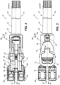
- the blower 10 may include two battery interfaces 36a, 36b each configured to receive a battery pack 40a, 40b and each electrically coupled to the fan 14, the PCBA 44, and the trigger 48.
- the battery interfaces 36a, 36b may be positioned at a same axial distance along the longitudinal axis LA relative to the inlet 26. As a result, only the battery pack 40a and the battery interface 36a are visible in FIG. 1 .
- the housing 18 may be provided as two clamshell halves 18a, 18b.
- the clamshell halves 18a, 18b may be generally split along a plane P ( FIGS.
- clamshell halves 18a, 18b may be split by a different plane which is oriented differently than the longitudinal plane P.
- other embodiments may have clamshell halves 18a, 18b are spaced laterally but otherwise parallel with the longitudinal plane P.
- Still other embodiments may have clamshell halves 18a, 18b split by differently oriented planes.
- the distal projection 56 is intersected by the plane P. In the illustrated embodiment, the distal projection 56 is bisected by the plane P. As shown in FIG.
- the battery interface 36a (i.e., a "first battery interface”) is coupled to the distal projection 56 on a first lateral side P1 of the plane P.
- the battery interface 36b (i.e., a "second battery interface”) is coupled to the distal projection 56 on a second lateral side P2 of the plane P.
- the second lateral side P2 is opposite the first lateral side P1. Accordingly, when the battery interface 36a receives the battery pack 40a (i.e., a "first battery”), the entirety of the battery pack 40a may be positioned on the first lateral side P1.
- the battery interface 36b receives the battery 40b (i.e., a "second battery")
- the entirety of the battery 40b may be positioned on the second lateral side P2.
- the plane P may intersect and/or bisect many components of the blower 10 including but not limited to the handle portion 64, the trigger 48, the user interface 52, the fan 14, the PCBA 44, and the foot 72.
- the battery packs 40a, 40b are selectively couplable to the battery interface 36a, 36b. While securing at least one of the battery packs 40a, 40b to the corresponding battery interface 36a, 36b, a user translates the battery pack 40a, 40b along an arrow A1 ( FIGS. 1-3 , 6 ) to engage the corresponding battery interface 36a, 36b.
- the arrow A1 is generally directed along the reference line RL1, and is thus transverse to the longitudinal axis LA.
- the arrow A1 generally is angled relative to the longitudinal axis LA by the angle AN1, and extends towards the inlet 26.
- the arrow A1 generally represents an insertion direction of the battery packs 40a, 40b.
- the user While removing at least one of the battery pack 40a, 40b from the corresponding battery interface 36a, 36b, the user translates the battery pack 40a, 40b along an arrow A2 ( FIGS. 1-3 , 6 ) to disengage the battery pack 40a, 40b from the corresponding battery interface 36a, 36b.
- the arrow A2 is angled relative to the longitudinal axis LA by the angle AN1, and extends away from the inlet 26.
- the arrow A2 generally represents a removal direction of the battery packs 40a, 40b.
- the arrow A2 generally opposes the arrow A1. As shown in FIG.
- the battery packs 40a, 40b when secured to the battery interfaces 36a, 36b, may permit fluid flow to the inlet 26 along an axial direction parallel to the longitudinal axis LA. In other words, at least a portion of the inlet 26 is offset in an axial direction parallel to the longitudinal axis LA from the battery packs 40a, 40b.
- Other types of battery packs 40a, 40b e.g., "stick” battery packs
- other battery packs 40a, 40b e.g., "stick” battery packs
- each battery pack 40a, 40b is a high-performance battery pack 40a, 40b.
- each battery pack 40a, 40b is a lithium-based.
- Other battery packs 40a, 40b may be nickel-based or have differing chemistries.
- the battery packs 40a, 40b may be a high-output battery pack (e.g., 6.0 Ah), such as the M18 TM REDLITHIUM TM HIGH OUTPUT TM XC6.0 battery pack, manufactured and sold by Milwaukee Electric Tool, Milwaukee, Wis.
- Such battery packs 40a, 40b weighs approximately 2.3 pounds (1.0 kilograms).
- These battery packs 40a, 40b and/or other compatible battery packs 40a, 40b may combine to provide up to 3000 Watts of input power (e.g., electrical input power) to the fan 14.
- This combination may include either one of the battery packs 40a, 40b or both the battery packs 40a, 40b.
- the battery packs 40a, 40b may combine to provide between 1500-3000 Watts of input power (inclusive) to the fan 14.
- the battery packs 40a, 40b may combine to provide between 1000-2000 Watts of input power (inclusive) to the fan 14.
- the battery packs 40a, 40b may combine to provide between 500-1300 Watts of input power (inclusive) to the fan 14.
- the battery packs 40a, 40b may provide at least 500 Watts of input power to the fan 14. In some embodiments, the battery packs 40a, 40b may combine to provide approximately 1000 Watts of input power to the fan 14. In some embodiments, the battery packs 40a, 40b may combine to provide approximately 900 Watts of input power to the fan 14.
- the battery packs 40a, 40b may provide approximately 900 Watts of input power to the fan 14.
- the battery packs 40a, 40b may provide at least 2000 Watts of input power to the fan 14.
- the battery packs 40a, 40b may provide approximately 1000 Watts of input power to the fan 14.
- the battery packs 40a, 40b may provide up to 3000 Watts of input power to the fan 14.
- Other configurations, combinations, and resultant input power to the fan 14 are possible.
- Each battery pack 40a, 40b may be operable to provide at least 1000 Watts of electrical input power to the fan 14.
- each battery pack 40a, 40b has an operating voltage of approximately 18 volts.
- Each battery pack 40a, 40b may have, for example, an output current of 6.0 amps.
- the blower 10 includes two battery packs 40a, 40b, each coupled to a corresponding battery interface 36a, 36b. Accordingly, the battery packs 40a, 40b of the blower 10 may provide a total of at least 2000 Watts of input power (e.g., electrical input power) to the fan 14.
- the illustrated blower 10 may have an operating voltage of approximately 36 volts, where each battery pack 40a, 40b provides an operating voltage of approximately 18 volts.
- multiple (i.e., at least two) battery packs 40a, 40b may be electrically coupled to a single battery interface 36a.
- Other suitable battery packs 40a, 40b may have different operating voltages, output currents, power outputs, and/or different weights.
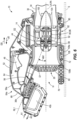
- FIG. 6 illustrates the fan 14 and the internal components of the housing 18 in detail.
- the fan 14 includes a motor 84 and an impeller 88.
- the motor 84 includes a rotor 92 and a stator 96.
- the stator 96 is secured to the fan portion 22 of the housing 18.
- the rotor 92 is configured to rotate along the rotational axis RA upon excitation of the fan 14 by the trigger 48.
- the rotor 92 is coupled to the impeller 88 for co-rotation therewith.
- the impeller 88 is dimensioned to generate fluid flow upon rotation of the rotor 92, the fluid being drawn in through the inlet 26 and expelled from the outlet 30.
- the impeller 88 is closer to the inlet 26 than the motor 84.
- the motor 84 is closer to the outlet 30 than the impeller 88.
- the fan 14 may further include a nose cone 100.
- the nose cone 100 may be stationary, and may be coupled to the fan portion 22 of the housing 18.
- the nose cone 100 is positioned further from the inlet 26 than the motor 84.
- the nose cone 100 may include a plurality of rectifiers 104 configured to straighten the fluid flow generated by the impeller 88.
- the rectifiers 104 may inhibit or dampen the generation of exhaust fluid flow vortices.
- the inlet 26 may be funnel-shaped or bell-shaped such that fluid passing through the inlet 26 is compressed and sped up as it passes through the housing 18.
- the exhaust tube 34 may also be funnel-shaped or bell-shaped such that fluid passing out the outlet 30 and along the exhaust tube 34 is compressed and sped up as it passes through the exhaust tube 34.
- the blower 10 includes an intake cone 108.
- the intake cone 108 includes a rigid housing 108a and a truncated foam bell 108b.
- the foam bell 108b may be configured to dampen sound generated by the fan 14.
- the intake cone 108 has an intake diameter D1 adjacent the intake grate 60 larger than an output diameter D2 adjacent the fan 14.
- the intake cone 108 varies in diameter along the longitudinal axis LA.
- the housing 108a and the foam bell 108b are each generally truncated bell shaped with intake diameters D1 being larger than the output diameters D2 thereof.
- the housing 108a and the bell 108b are superimposed upon each other in a direction extending away from the longitudinal axis LA.
- the illustrated housing 108a is positioned further from the longitudinal axis LA than (e.g., radially outward of the) foam bell 108b. However, in other constructions, the opposite may be employed with the housing 108a positioned closer to the longitudinal axis LA than the foam bell 108b.
- an interface between the housing 108a and the foam bell 108b may include an air, particulate, and/or sound permeable membrane, window, grate, reduced thickness portion, or aperture (not shown). Accordingly, sound generated by the fan 14 may be dampened by the foam bell 108b. Size, shape, and dimensions of the membrane, window, grate, reduced thickness portion, or aperture may be optimized to achieve desired sound dampening.
Landscapes
- Engineering & Computer Science (AREA)
- Mechanical Engineering (AREA)
- General Engineering & Computer Science (AREA)
- Life Sciences & Earth Sciences (AREA)
- Environmental Sciences (AREA)
- Structures Of Non-Positive Displacement Pumps (AREA)
- Secondary Cells (AREA)
Applications Claiming Priority (2)
| Application Number | Priority Date | Filing Date | Title |
|---|---|---|---|
| US202263321899P | 2022-03-21 | 2022-03-21 | |
| US202263330883P | 2022-04-14 | 2022-04-14 |
Publications (2)
| Publication Number | Publication Date |
|---|---|
| EP4249754A2 true EP4249754A2 (de) | 2023-09-27 |
| EP4249754A3 EP4249754A3 (de) | 2023-11-29 |
Family
ID=85724588
Family Applications (1)
| Application Number | Title | Priority Date | Filing Date |
|---|---|---|---|
| EP23163197.9A Pending EP4249754A3 (de) | 2022-03-21 | 2023-03-21 | Batteriebetriebenes axialgebläse |
Country Status (2)
| Country | Link |
|---|---|
| US (1) | US12352274B2 (de) |
| EP (1) | EP4249754A3 (de) |
Families Citing this family (4)
| Publication number | Priority date | Publication date | Assignee | Title |
|---|---|---|---|---|
| EP4042861B1 (de) * | 2021-02-12 | 2023-12-20 | Andreas Stihl AG & Co. KG | Schutzvorrichtung für einen ansaug- oder blaskanal eines arbeitsgerätes und arbeitsgerät mit einer schutzvorrichtung |
| USD1046337S1 (en) * | 2022-09-01 | 2024-10-08 | Zhejiang Dadao Electric Appliance Co., Ltd. | Blower |
| US12704128B2 (en) * | 2023-10-23 | 2026-08-11 | Milwaukee Electric Tool Corporation | Blower / vac tools with improved fan blade noise |
| CN117927489B (zh) * | 2024-03-21 | 2024-06-18 | 浙江白马科技有限公司 | 花园鼓风机 |
Family Cites Families (243)
| Publication number | Priority date | Publication date | Assignee | Title |
|---|---|---|---|---|
| BE370536A (de) | 1929-12-26 | |||
| US2284586A (en) | 1941-07-10 | 1942-05-26 | Joseph B Mcdermott | Visible multiple record |
| US2938527A (en) | 1954-02-23 | 1960-05-31 | Allis Chalmers Mfg Co | Control system for hydraulic turbines |
| US2768782A (en) | 1954-07-02 | 1956-10-30 | Arthur K Tateishi | Electric fan |
| DE1228640B (de) | 1962-03-14 | 1966-11-17 | Gea Luftkuehler Happel Gmbh | Luftgekuehlter Waermeaustauscher, dessen Axialluefter auf einem Stuetzbock gelagert ist |
| US3407431A (en) | 1966-03-02 | 1968-10-29 | Steve J. Melnik | Powered tool for cleaning typewriter type |
| US3346174A (en) | 1966-07-05 | 1967-10-10 | Trane Co | Compact axial flow fan |
| US3540547A (en) | 1968-12-31 | 1970-11-17 | Charles Waddell Coward Jr | Acoustical systems for air moving devices |
| FR2224713A1 (en) | 1973-04-06 | 1974-10-31 | Grondin Urbain | Self-contained hand-held de-icer unit - has battery operated heater and blower and telescopic nozzle |
| US4185688A (en) | 1977-12-22 | 1980-01-29 | General Electric Company | Cooler fan noise suppressor |
| US4222318A (en) | 1978-12-11 | 1980-09-16 | Patton Electric Co., Inc. | Combination window and floor fan |
| US4413371A (en) | 1981-06-29 | 1983-11-08 | Emerson Electric Co. | Blower attachment for portable power unit |
| GB8408772D0 (en) | 1984-04-05 | 1984-05-16 | Black & Decker Inc | Tool stand |
| US4615069A (en) | 1984-10-19 | 1986-10-07 | Black & Decker Inc. | Apparatus for collecting debris |
| US4597203A (en) | 1985-08-12 | 1986-07-01 | Middleton Carlisle A | Convertible snowblower using rectangular shroud interface |
| US4692091A (en) | 1985-09-23 | 1987-09-08 | Ritenour Paul E | Low noise fan |
| US4696450A (en) | 1986-04-04 | 1987-09-29 | Huang Kuo C | Fan motor assembly support frame |
| GB2188963B (en) | 1986-04-14 | 1989-11-22 | Johnston Eng Ltd | Improvements in or relating to road sweeping vehicles |
| US4734017A (en) | 1986-08-07 | 1988-03-29 | Levin Mark R | Air blower |
| US4792286A (en) | 1987-07-23 | 1988-12-20 | Textron Inc. | Blower-vacuum apparatus |
| US4794225A (en) | 1987-10-09 | 1988-12-27 | Maese Hector L | Tube axial handheld blow dryer for hair |
| US4884314A (en) | 1987-11-12 | 1989-12-05 | Black & Decker Inc. | Portable blower |
| US4945604A (en) | 1987-11-12 | 1990-08-07 | Black & Decker Inc. | Portable blower |
| US4838151A (en) | 1988-01-27 | 1989-06-13 | Holmes Products Corp. | Combination window and floor fan |
| DE3812105A1 (de) | 1988-04-12 | 1988-09-08 | Uwe Gruenewald | Kombinationsgeraet garten und strasse |
| US4821366A (en) | 1988-05-03 | 1989-04-18 | Cic Int'l. Corp. | Wet-dry vacuum cleaner |
| US4800616A (en) | 1988-05-06 | 1989-01-31 | Steamatic, Inc. | Air powered duct cleaner and crawler |
| US4981414A (en) | 1988-05-27 | 1991-01-01 | Sheets Herman E | Method and apparatus for producing fluid pressure and controlling boundary layer |
| DE8815616U1 (de) | 1988-12-16 | 1989-02-02 | Diehl, Klaus, Dipl.-Ing. (FH), 6700 Ludwigshafen | Vorrichtung zum Trocknen, Erwärmen und Reinigen von Oberflächen des Straßen- und Wegebaues |
| US5035586A (en) | 1989-04-19 | 1991-07-30 | White Consolidated Industries, Inc. | Portable hand-held blower/vacuum unit with resilient engine mounting system |
| US5269665A (en) | 1989-04-19 | 1993-12-14 | White Consolidated Industries, Inc. | Portable hand-held blower/vacuum unit with resilient engine mounting system |
| JP2749885B2 (ja) | 1989-07-20 | 1998-05-13 | 松下電工株式会社 | 送風装置 |
| CN2053083U (zh) | 1989-10-05 | 1990-02-21 | 梁永盛 | 微型多用吸吹尘器 |
| JPH0489891U (de) | 1990-12-19 | 1992-08-05 | ||
| US5267371A (en) | 1992-02-19 | 1993-12-07 | Iona Appliances Inc. | Cyclonic back-pack vacuum cleaner |
| US5383427A (en) | 1993-07-19 | 1995-01-24 | Wci Outdoor Products, Inc. | Two-cycle, air-cooled uniflow gasoline engine for powering a portable tool |
| GB9406532D0 (en) | 1994-03-31 | 1994-05-25 | Black & Decker Inc | Blower vacuum |
| JP3491342B2 (ja) | 1994-06-27 | 2004-01-26 | 松下電工株式会社 | 軸流ファン |
| US5560076A (en) | 1994-11-14 | 1996-10-01 | Hoovine Industrial Limited | Combined vacuum cleaner and torch |
| JPH09112268A (ja) | 1995-10-19 | 1997-04-28 | Hitachi Constr Mach Co Ltd | エンジン冷却装置及び建設機械 |
| SE9503753D0 (sv) | 1995-10-25 | 1995-10-25 | Electrolux Ab | Anordning vid en dammsugare |
| US6006400A (en) | 1996-02-26 | 1999-12-28 | Presenza; Tom | Electric backpack blower |
| JP3437894B2 (ja) | 1996-07-01 | 2003-08-18 | 株式会社共立 | ブロワパイプへの消音装置の取付方法 |
| US5768749A (en) | 1996-07-26 | 1998-06-23 | Ryobi North America, Inc. | Portable air blower |
| US5722111A (en) | 1996-07-26 | 1998-03-03 | Ryobi North America | Blower vacuum |
| JP3913334B2 (ja) | 1996-11-20 | 2007-05-09 | 三菱電機株式会社 | 換気送風装置および換気送風システム |
| JPH10266867A (ja) | 1997-03-19 | 1998-10-06 | Kioritz Corp | 携帯式動力作業機 |
| US6158082A (en) | 1998-03-10 | 2000-12-12 | The Toro Company | Portable blower with blower tube noise reduction |
| US5979013A (en) | 1998-03-10 | 1999-11-09 | The Toro Company | Portable blower with noise reduction |
| US20020000020A1 (en) | 1998-05-21 | 2002-01-03 | Jimmie C. Walker | Rechargeable industrial broom |
| JP2000018720A (ja) | 1998-07-01 | 2000-01-18 | Yoko Kasai | 熱風送風機 |
| US6305048B1 (en) | 1999-03-03 | 2001-10-23 | Harold Salisian | Electric backpack blower and accessory operator |
| US6105206A (en) | 1999-04-13 | 2000-08-22 | Department Of Water And Power City Of Los Angeles | Portable electrically powered blower apparatus |
| US6689225B2 (en) | 1999-05-21 | 2004-02-10 | Vortex Holding Company | Toroidal vortex vacuum cleaner with alternative collection apparatus |
| US7143468B2 (en) | 1999-05-21 | 2006-12-05 | Lewis Illingworth | Vortex vacuum cleaner nozzle with means to prevent plume formation |
| US6802881B2 (en) | 1999-05-21 | 2004-10-12 | Vortex Hc, Llc | Rotating wave dust separator |
| US20030136094A1 (en) | 1999-05-21 | 2003-07-24 | Lewis Illingworth | Axial flow centrifugal dust separator |
| US20040139709A1 (en) | 1999-05-21 | 2004-07-22 | Lewis Illingworth | Dynamic transfer chamber separator |
| US6957472B2 (en) | 1999-05-21 | 2005-10-25 | Vortex Hc, Llc | Cannister and upright vortex vacuum cleaners |
| US20030167741A1 (en) | 1999-05-21 | 2003-09-11 | Lewis Illingworth | Combined toroidal and cylindrical vortex dust separator |
| US6811687B2 (en) | 1999-05-21 | 2004-11-02 | Vortex Holding Company | Vortex pool cleaner |
| US6616094B2 (en) | 1999-05-21 | 2003-09-09 | Vortex Holding Company | Lifting platform |
| US6464459B2 (en) | 1999-05-21 | 2002-10-15 | Avionic Instruments, Inc. | Lifting platform with energy recovery |
| US20030150198A1 (en) | 1999-05-21 | 2003-08-14 | Lewis Illingworth | Filterless folded and ripple dust separators and vacuum cleaners using the same |
| US6719830B2 (en) | 1999-05-21 | 2004-04-13 | Vortex Holding Company | Toroidal vortex vacuum cleaner centrifugal dust separator |
| US6520449B2 (en) | 1999-05-21 | 2003-02-18 | Vortex Holding Company | Lifting platform with positive horizontal stability |
| US6497553B2 (en) | 1999-05-21 | 2002-12-24 | Vortex Holding Company | Vortex attractor |
| US6565321B1 (en) | 1999-05-21 | 2003-05-20 | Vortex Holding Company | Vortex attractor |
| US6623352B2 (en) | 1999-05-21 | 2003-09-23 | Vortex Holding Company | Vortex air barrier |
| US6595753B1 (en) | 1999-05-21 | 2003-07-22 | A. Vortex Holding Company | Vortex attractor |
| US20040139710A1 (en) | 1999-05-21 | 2004-07-22 | Lewis Illingworth | Passive transfer chamber separator |
| US6619922B2 (en) | 1999-05-21 | 2003-09-16 | Vortex Holding Company | Vortex attractor for planar and non-planar surfaces |
| US6543726B2 (en) | 1999-05-21 | 2003-04-08 | Vortex Holding Company | Fluid flow straightening techniques |
| US6687951B2 (en) | 1999-05-21 | 2004-02-10 | Vortex Holding Company | Toroidal vortex bagless vacuum cleaner |
| FR2794195B1 (fr) | 1999-05-26 | 2002-10-25 | Moulinex Sa | Ventilateur equipe d'une manche a air |
| US6244823B1 (en) | 1999-06-22 | 2001-06-12 | Holmes Products Corporation | Dual positionable oscillating fan |
| JP2001153096A (ja) | 1999-11-30 | 2001-06-05 | Maruyama Mfg Co Ltd | 遠心送風機及び携帯式送風装置 |
| SE515429C2 (sv) | 1999-12-03 | 2001-08-06 | Electrolux Ab | Lövblåsare |
| DE19959557B4 (de) | 1999-12-10 | 2015-12-03 | Andreas Stihl Ag & Co. | Blasgerät |
| DE29921751U1 (de) | 1999-12-11 | 2000-02-10 | Kersten, Georg, Dipl.-Ing., 46459 Rees | Laub-Blas- und Sauggerät |
| JP3827055B2 (ja) | 2000-01-04 | 2006-09-27 | 株式会社丸山製作所 | 携帯式送風機 |
| US7922470B2 (en) | 2000-04-07 | 2011-04-12 | Joseph Daniel R | Apparatus for automatic control of cage size in an extruded film production line |
| JP2002155899A (ja) | 2000-11-21 | 2002-05-31 | Kioritz Corp | 背負架台 |
| US6442790B1 (en) | 2001-02-09 | 2002-09-03 | The Toro Company | Portable blower/vacuum having air inlet cover attachable to blower tube |
| US20020148069A1 (en) | 2001-04-13 | 2002-10-17 | Lewis Illingworth | Toroidal vortex nozzle |
| US6514036B2 (en) | 2001-04-27 | 2003-02-04 | Black & Decker Inc. | Radial flow fan with impeller having blade configuration for noise reduction |
| US6490756B2 (en) | 2001-04-27 | 2002-12-10 | Black & Decker Inc. | Blower having fan oriented perpendicular to discharge nozzle |
| JP4055106B2 (ja) | 2001-05-24 | 2008-03-05 | 株式会社共立 | ブロワー搭載背負形作業機 |
| JP3682604B2 (ja) | 2002-03-07 | 2005-08-10 | 株式会社共立 | 送風作業機及び通気カバー |
| FR2840172B1 (fr) | 2002-05-29 | 2006-08-18 | Didier Tronc | Canne chauffante pour lit |
| US20030221399A1 (en) | 2002-05-31 | 2003-12-04 | Hall Glenn A. | Changeable power implements |
| GB2390118A (en) | 2002-06-25 | 2003-12-31 | Shamseldin Mahmoud | Electrical heating and demisting device for a vehicle |
| CN2580819Y (zh) | 2002-11-21 | 2003-10-22 | 揭阳市华能达电器有限公司 | 带后风罩电吹风 |
| US6915641B2 (en) | 2003-01-14 | 2005-07-12 | Mark R. Harvie | Personal cooling and heating system |
| CN2628767Y (zh) | 2003-05-28 | 2004-07-28 | 达隆科技股份有限公司 | 扇叶轮 |
| US7600290B1 (en) | 2003-09-02 | 2009-10-13 | Twindstorm Llc | Multi-blower |
| US7959657B1 (en) | 2004-07-07 | 2011-06-14 | Harsy Douglas R | Portable thermal therapeutic apparatus and method |
| US7300484B2 (en) | 2004-09-17 | 2007-11-27 | Andreas Stihl Ag & Co. Kg | Blower having a carrying frame |
| US20060123635A1 (en) | 2004-12-09 | 2006-06-15 | Heow, Inc. | Combination blower, trimmer and edger for tending vegetation |
| DE102005003275A1 (de) | 2005-01-25 | 2006-07-27 | Andreas Stihl Ag & Co. Kg | Rückentragbares Saug-/Blasgerät |
| DE102005007298B4 (de) | 2005-02-17 | 2015-01-22 | Andreas Stihl Ag & Co. Kg | Handgeführtes, tragbares Saug-/Blasgerät |
| US7845048B1 (en) | 2005-06-21 | 2010-12-07 | Gerald Bailey | Portable air-blower for removing debris and the like from a putting green surface |
| US20070209346A1 (en) | 2006-03-13 | 2007-09-13 | Bovo Peter J | Combined weed whacker, blower and vacuum apparatus |
| US7850513B1 (en) | 2006-05-12 | 2010-12-14 | University Of Central Florida Research Foundation, Inc. | High efficiency solar powered fans |
| JP2008002310A (ja) | 2006-06-21 | 2008-01-10 | Kioritz Corp | 背負式送風機 |
| US7739773B2 (en) | 2006-08-10 | 2010-06-22 | Andreas Stihl Ag & Co. Kg | Portable blower |
| DE102007037011A1 (de) | 2006-08-10 | 2008-02-14 | Andreas Stihl Ag & Co. Kg | Handgeführtes Blasgerät |
| CN101135139B (zh) | 2006-08-30 | 2011-01-12 | 苏州宝时得电动工具有限公司 | 吹吸机 |
| US7728534B2 (en) | 2006-10-17 | 2010-06-01 | Mtd Products Inc | Hybrid electric lawnmower |
| US7735188B2 (en) | 2006-12-22 | 2010-06-15 | The Toro Company | Air inlet cover and portable blower/vacuum incorporating same |
| CN101260833A (zh) | 2007-03-08 | 2008-09-10 | 邓庚厚 | 一种由缸内直轴传递动力的发动机 |
| US7841045B2 (en) | 2007-08-06 | 2010-11-30 | Wd-40 Company | Hand-held high velocity air blower |
| DE102007045146A1 (de) | 2007-09-20 | 2009-05-28 | Evonik Degussa Gmbh | Einachsfahrzeug mit einer Plattform und/oder einem Sitz für einen Fahrer |
| US7607244B2 (en) | 2007-10-09 | 2009-10-27 | Viv Engineering Inc. | Snow-plowing apparatus |
| US7870640B2 (en) | 2008-03-31 | 2011-01-18 | The Toro Company | Convertible blower/vacuum |
| JP2009264300A (ja) | 2008-04-25 | 2009-11-12 | Hitachi Koki Co Ltd | ブロワ装置 |
| US8074320B2 (en) | 2008-05-15 | 2011-12-13 | Rachael Anne Batchelder | Autonomous blower for debris herding |
| US20100003149A1 (en) | 2008-07-03 | 2010-01-07 | Nelson Daniel A | Rear-positioned filter mount for use with a box or cage fan for reducing dust emission and improving interior air quality |
| JP4510910B2 (ja) | 2008-07-22 | 2010-07-28 | 株式会社協同 | ブロアー |
| US20100192314A1 (en) | 2009-02-03 | 2010-08-05 | Makita Corporation | Handy cleaners |
| WO2010111339A1 (en) | 2009-03-25 | 2010-09-30 | Delta T Corporation | High efficiency ducted fan |
| ES2356873B1 (es) | 2009-07-29 | 2012-03-15 | Soler & Palau Research S.L. | Ventilador helicocentr�?fugo insonorizado. |
| WO2011016101A1 (ja) | 2009-08-03 | 2011-02-10 | ハスクバーナ・ゼノア株式会社 | エンジンブロワ |
| EP3251716B1 (de) | 2009-08-11 | 2019-02-20 | ResMed Motor Technologies Inc | Ventilator mit einem einstufigen achsensymmetrischen gebläse |
| JP2011127541A (ja) | 2009-12-18 | 2011-06-30 | Makita Corp | 背負式作業具 |
| US8267674B2 (en) | 2010-02-04 | 2012-09-18 | Robert Bosch Gmbh | Centrifugal blower assembly |
| US7941894B1 (en) | 2010-02-05 | 2011-05-17 | Tony Skorput | Golf course green debris removal device |
| JP5461221B2 (ja) * | 2010-02-12 | 2014-04-02 | 株式会社マキタ | 複数のバッテリパックを電源とする電動工具 |
| KR200458939Y1 (ko) | 2010-03-26 | 2012-03-21 | 김수우 | 광고 선전 풍선 |
| GB201010810D0 (en) | 2010-06-25 | 2010-08-11 | Ntnu Technology Transfer As | Oil removal |
| FR2964987B1 (fr) | 2010-09-20 | 2012-10-05 | Pellenc Sa | Souffleur electroportatif. |
| DE102010046565A1 (de) | 2010-09-27 | 2012-03-29 | Andreas Stihl Ag & Co. Kg | Handgeführtes Blasgerät |
| JP5572060B2 (ja) | 2010-10-22 | 2014-08-13 | 株式会社やまびこ | 送風作業機 |
| US9277844B1 (en) | 2010-10-25 | 2016-03-08 | Luis A. Millan | Apparatus for vacuum and sweeping |
| KR101048421B1 (ko) | 2010-11-01 | 2011-07-14 | 김남현 | 송풍 기능을 포함하는 배낭 |
| DE102010054841A1 (de) | 2010-12-16 | 2012-06-21 | Andreas Stihl Ag & Co. Kg | Blasgerät mit einem elektrischen Antriebsmotor |
| DE202010016820U1 (de) | 2010-12-21 | 2012-03-26 | Ebm-Papst Mulfingen Gmbh & Co. Kg | Diffusor für einen Ventilator sowie Ventilatoranordnung mit einem derartigen Diffusor |
| CN202015678U (zh) | 2011-02-21 | 2011-10-26 | 王霞 | 婴幼儿用痱子粉喷涂器 |
| WO2012113414A1 (en) | 2011-02-22 | 2012-08-30 | Aktiebolaget Electrolux | Vacuum cleaner |
| JP5717464B2 (ja) | 2011-02-24 | 2015-05-13 | 株式会社やまびこ | ブロワ |
| CN201968600U (zh) | 2011-03-10 | 2011-09-14 | 苏州市凯丽保姆电器有限公司 | 静音吸尘器 |
| DE102011014344B4 (de) | 2011-03-18 | 2025-02-06 | Andreas Stihl Ag & Co. Kg | Blasgerät |
| FR2973815B1 (fr) | 2011-04-07 | 2014-08-29 | Pellenc Sa | Souffleur electroportatif autonome a vitesse de sortie d'air modulable |
| FR2973847B1 (fr) | 2011-04-11 | 2015-10-30 | Pellenc Sa | Helice de generateur de flux d'air pulse, en particulier pour souffleur portatif. |
| JP2012217782A (ja) | 2011-04-14 | 2012-11-12 | Panasonic Corp | 空気吸引噴射装置およびそれを用いた電気掃除機 |
| CN102296555B (zh) | 2011-05-24 | 2015-05-13 | 宁波大叶园林设备有限公司 | 一种低振动树叶吹吸机的改进 |
| CN202157288U (zh) | 2011-05-24 | 2012-03-07 | 宁波大叶园林设备有限公司 | 低振动树叶吹吸机 |
| EP2545766B1 (de) | 2011-07-14 | 2014-07-09 | Black & Decker Inc. | Reststoffabblas- und/oder -ansaugvorrichtung |
| US20120093490A1 (en) | 2011-12-29 | 2012-04-19 | Joel Steinberg | Portable ice melting device |
| US20130180495A1 (en) | 2012-01-14 | 2013-07-18 | Jay S. Veerathappa | Detachable Power Head |
| US20130183141A1 (en) | 2012-01-18 | 2013-07-18 | Foshan Shunde Xinshengyuan Electrical Appliances Co., Ltd. | Air moving devices |
| EP2617281B1 (de) | 2012-01-23 | 2014-08-27 | Black & Decker Inc. | Vorrichtung zum Sammeln von Gartenabfällen |
| JP5975732B2 (ja) | 2012-05-23 | 2016-08-23 | 株式会社マキタ | 背負式作業機 |
| US9167751B2 (en) | 2012-07-09 | 2015-10-27 | Techtronic Outdoor Products Technology Limited | Backpack leaf blower |
| US9551429B2 (en) | 2012-07-18 | 2017-01-24 | Fike Corporation | Rupture disc having laser-defined reversal initiation and deformation control features |
| US8510910B1 (en) | 2012-07-24 | 2013-08-20 | Mark Ramsey | Air blower device for cleaning a rain gutter and other elevated surfaces |
| JP5979364B2 (ja) * | 2012-08-20 | 2016-08-24 | 日立工機株式会社 | 携帯用ブロワ |
| JP5983929B2 (ja) * | 2012-08-20 | 2016-09-06 | 日立工機株式会社 | 携帯用ブロワ |
| JP5959993B2 (ja) | 2012-08-24 | 2016-08-02 | 株式会社マキタ | 充電式ファン装置 |
| JP2014148950A (ja) | 2013-02-01 | 2014-08-21 | Makita Corp | 電動ブロワ |
| CN106284153B (zh) | 2015-05-11 | 2018-01-16 | 南京德朔实业有限公司 | 吹风机 |
| US11248626B2 (en) | 2013-02-20 | 2022-02-15 | Chervon (Hk) Limited | Handheld blower |
| CN106284148B (zh) | 2015-05-11 | 2018-05-11 | 南京德朔实业有限公司 | 吹风机 |
| US10337526B2 (en) * | 2015-05-11 | 2019-07-02 | Chervon (Hk) Limited | Blower |
| US10000900B2 (en) | 2013-02-20 | 2018-06-19 | Chervon (Hk) Limited | Handheld blower having engine cooling flow |
| US9603497B2 (en) | 2013-02-20 | 2017-03-28 | Chevron (Hk) Limited | Handheld blower |
| CN104074155B (zh) | 2013-03-29 | 2016-09-07 | 南京德朔实业有限公司 | 手持式吹风机 |
| CN106284149B (zh) | 2015-05-11 | 2018-05-11 | 南京德朔实业有限公司 | 吹风机 |
| CN203270492U (zh) | 2013-05-15 | 2013-11-06 | 江门市朝扬精密制造有限公司 | 一种落叶吹风机 |
| US9456722B2 (en) | 2013-08-13 | 2016-10-04 | Emerson Electric Co. | Backpack vacuum cleaner |
| CN203498784U (zh) | 2013-09-18 | 2014-03-26 | 常州合力电器有限公司 | 手提吹风机 |
| CN104564839B (zh) | 2013-10-11 | 2017-01-04 | 南京德朔实业有限公司 | 一种吹风机及其风筒 |
| EP2875718B1 (de) | 2013-11-22 | 2019-06-05 | Andreas Stihl AG & Co. KG | Handgeführtes Arbeitsgerät mit einem Blasrohr |
| CN103671175B (zh) | 2013-12-31 | 2016-08-03 | 常州格力博有限公司 | 轴流吹风机 |
| CN106133329B (zh) * | 2014-03-17 | 2020-01-17 | 胡斯华纳有限公司 | 动力设备冷却系统 |
| JP6481257B2 (ja) | 2014-03-31 | 2019-03-13 | 工機ホールディングス株式会社 | 電気機器 |
| JP6358833B2 (ja) | 2014-04-03 | 2018-07-18 | 株式会社やまびこ | 背負式作業機 |
| EP3133973B1 (de) | 2014-04-24 | 2018-02-28 | Husqvarna AB | Laubbläser mit einer öse |
| US10330116B2 (en) * | 2014-04-24 | 2019-06-25 | Husqvarna Ab | Noise reduction system for a blower |
| US10330333B2 (en) | 2014-04-29 | 2019-06-25 | Bryan Kaleta | Portable misting fan with pivoting head |
| JP6242758B2 (ja) | 2014-06-30 | 2017-12-06 | 株式会社マキタ | 送風作業機 |
| CN204126922U (zh) | 2014-09-09 | 2015-01-28 | 苏州金莱克精密机械有限公司 | 吹风机 |
| CN106714642A (zh) | 2014-09-15 | 2017-05-24 | 翼科技有限责任公司 | 便携式电动碎屑鼓风机设备 |
| EP3206545B1 (de) | 2014-10-16 | 2021-09-29 | Techtronic Industries Company Limited | Verbesserte batterieentfernung für einen staubsauger |
| US20160108924A1 (en) | 2014-10-17 | 2016-04-21 | Mean Green Products, LLC | Battery-powered, low-noise backpack blower |
| JP6368616B2 (ja) * | 2014-10-21 | 2018-08-01 | 株式会社マキタ | 動力送風作業機 |
| US10327392B2 (en) | 2014-11-05 | 2019-06-25 | Mean Green Products, LLC | Battery-powered debris blower |
| US9907234B2 (en) | 2014-11-20 | 2018-03-06 | Black & Decker, Inc. | Battery-powered backpack blower |
| US9991825B1 (en) * | 2014-11-24 | 2018-06-05 | The Toro Company | Outdoor power equipment system with modular motor and modular battery |
| WO2016082759A1 (zh) | 2014-11-28 | 2016-06-02 | 苏州宝时得电动工具有限公司 | 吹吸装置 |
| EP3225740B1 (de) | 2014-11-28 | 2021-11-10 | Positec Power Tools (Suzhou) Co., Ltd | Blas-/saugvorrichtung |
| US10227988B2 (en) | 2014-11-28 | 2019-03-12 | Positec Power Tools (Suzhou) Co., Ltd. | Blower and a blowing vacuum device |
| US10375901B2 (en) | 2014-12-09 | 2019-08-13 | Mtd Products Inc | Blower/vacuum |
| JP2016112523A (ja) * | 2014-12-16 | 2016-06-23 | 株式会社マキタ | 送風作業機 |
| AU2016200049B2 (en) | 2015-01-06 | 2020-01-02 | Techtronic Industries Co., Ltd. | Axial blower vacuum |
| EP3051271A1 (de) | 2015-01-27 | 2016-08-03 | Siemens Healthcare Diagnostics Products GmbH | Verfahren zur Bestimmung von Lipiden und anderen Störsubstanzen in Körperflüssigkeitsproben |
| US11067087B2 (en) | 2015-03-12 | 2021-07-20 | Black & Decker, Inc. | Axial-fan blower |
| CA3288581A1 (en) | 2015-03-26 | 2026-03-02 | Bayer Cropscience Lp | A novel paenibacillus strain, antifungal compounds, and methods for their use |
| CN206538723U (zh) | 2015-04-10 | 2017-10-03 | 苏州宝时得电动工具有限公司 | 吹吸装置 |
| JP6504898B2 (ja) | 2015-04-20 | 2019-04-24 | 株式会社マキタ | 背負い式流体装置 |
| DE112016001826T5 (de) | 2015-04-20 | 2018-01-11 | Makita Corporation | Auf dem Rücken getragene Blasarbeitsmaschine |
| JP6491025B2 (ja) | 2015-04-20 | 2019-03-27 | 株式会社マキタ | 背負い式ブロワ |
| US20160324380A1 (en) | 2015-05-07 | 2016-11-10 | Stanley Black & Decker Inc. | Axial fan blower and vacuum |
| EP3649847B1 (de) | 2015-05-28 | 2021-10-27 | Husqvarna AB | Gebläse mit verbesserter geräuschminderung |
| US20180087513A1 (en) | 2015-06-12 | 2018-03-29 | Tti (Macao Commercial Offshore) Limited | Axial fan blower |
| CN204722966U (zh) | 2015-07-01 | 2015-10-28 | 广东浩宇清洁环保设备有限公司 | 一种背式吸尘机 |
| CN204811640U (zh) | 2015-07-27 | 2015-12-02 | 山东博胜动力科技股份有限公司 | 一种便携式手提电动药液喷雾装置 |
| USD812825S1 (en) | 2015-10-13 | 2018-03-13 | Chevron (Hk) Limited | Blower |
| CN105248156A (zh) | 2015-10-13 | 2016-01-20 | 宁波大叶园林设备有限公司 | 含离心碳刷插头及卡线座电机的吹吸机 |
| WO2017101666A1 (zh) | 2015-12-16 | 2017-06-22 | 常州格力博有限公司 | 腰挂式吹风机 |
| CN205276194U (zh) | 2016-01-07 | 2016-06-01 | 宁波动一电器有限公司 | 背包式吹风机 |
| CN105485033B (zh) | 2016-01-07 | 2017-11-24 | 宁波动一电器有限公司 | 背包吹风机 |
| CN105586846B (zh) | 2016-02-22 | 2018-04-03 | 浙江普莱得电器有限公司 | 吹吸机 |
| JP2017172454A (ja) | 2016-03-23 | 2017-09-28 | 株式会社やまびこ | 送風作業装置 |
| JP2017172198A (ja) | 2016-03-23 | 2017-09-28 | 株式会社やまびこ | 送風作業装置 |
| CN107558422B (zh) | 2016-06-30 | 2020-06-23 | 南京德朔实业有限公司 | 手持式吹风机 |
| EP3498920A4 (de) | 2016-08-10 | 2020-04-01 | Positec Power Tools (Suzhou) Co., Ltd | Gartengebläse |
| CN205999837U (zh) | 2016-08-10 | 2017-03-08 | 苏州宝时得电动工具有限公司 | 吹风机 |
| CN206090426U (zh) | 2016-10-08 | 2017-04-12 | 浙江三锋实业股份有限公司 | 一种吹风机的吹风结构 |
| US10405707B2 (en) * | 2016-11-07 | 2019-09-10 | Nanjing Chervon Industry Co., Ltd. | Blower |
| CN206289575U (zh) | 2016-12-21 | 2017-06-30 | 惠安宏诚机械有限公司 | 一种园林多角度铲片吸叶机 |
| JP2018117505A (ja) | 2017-01-20 | 2018-07-26 | 日本電産株式会社 | モータ及びそれを備えた送風装置 |
| CN206480689U (zh) | 2017-02-28 | 2017-09-08 | 宁波动一电器有限公司 | 一种安全开关以及背包吹风机 |
| US11206961B2 (en) | 2017-03-08 | 2021-12-28 | Kyocera Industrial Tools Corporation | Sound absorption structure for air flow path in electric air flow generation device and electric vacuum |
| CN206815252U (zh) | 2017-04-26 | 2017-12-29 | 苏州宝时得电动工具有限公司 | 一种吹风机 |
| CN107201734B (zh) | 2017-06-08 | 2018-08-17 | 宁波大叶园林设备股份有限公司 | 行走式具永磁马达定子连风叶转动及风筒消声器的吹叶机 |
| CN107269550B (zh) | 2017-06-16 | 2019-08-13 | 宁波大叶园林设备股份有限公司 | 具锂电池驱动马达环周并列滤波消声风管的吹叶机 |
| JP2019018190A (ja) | 2017-07-21 | 2019-02-07 | 株式会社マキタ | 送風作業機 |
| US11695312B2 (en) * | 2017-09-01 | 2023-07-04 | Milwaukee Electric Tool Corporation | Electrostatic discharge dissipation structure |
| CN207498881U (zh) | 2017-09-20 | 2018-06-15 | 天佑电器(苏州)有限公司 | 一种吹气装置 |
| CN208965470U (zh) * | 2017-09-29 | 2019-06-11 | 南京德朔实业有限公司 | 吹风机 |
| WO2019062279A1 (zh) * | 2017-09-30 | 2019-04-04 | 南京德朔实业有限公司 | 吹风机 |
| DE202017106572U1 (de) | 2017-10-30 | 2018-01-31 | Nanjing Chervon Industry Co., Ltd. | Bläser |
| CN207582389U (zh) | 2017-11-22 | 2018-07-06 | 南京德朔实业有限公司 | 一种吹风机 |
| US10897858B2 (en) | 2017-11-30 | 2021-01-26 | Tti (Macao Commercial Offshore) Limited | Blower/mulcher |
| CN108476871A (zh) | 2018-02-06 | 2018-09-04 | 绍兴市上虞冠业电器有限公司 | 手持式吹风机 |
| SE542268C2 (en) | 2018-04-27 | 2020-03-31 | Husqvarna Ab | Debris blower |
| EP3626972B1 (de) * | 2018-09-21 | 2023-05-10 | Techtronic Outdoor Products Technology Limited | Elektrisches luftgebläse |
| KR102042387B1 (ko) | 2019-07-29 | 2019-11-07 | 주식회사 아임 | 헤어드라이기용 비등간격 블레이드를 구비한 고풍량 블로워 팬 |
| CN214742186U (zh) * | 2020-01-21 | 2021-11-16 | 创科无线普通合伙 | 鼓风机 |
| EP4114227A4 (de) * | 2020-03-04 | 2024-04-17 | Black & Decker, Inc. | Gebläse mit elektrostatischem entladungssystem |
| CN212508973U (zh) | 2020-05-27 | 2021-02-09 | 苏州宝时得电动工具有限公司 | 用于园林吹风机的风叶机构和园林吹风机 |
| WO2022028384A1 (zh) * | 2020-08-03 | 2022-02-10 | 南京德朔实业有限公司 | 吹风机 |
-
2023
- 2023-03-20 US US18/186,455 patent/US12352274B2/en active Active
- 2023-03-21 EP EP23163197.9A patent/EP4249754A3/de active Pending
Also Published As
| Publication number | Publication date |
|---|---|
| EP4249754A3 (de) | 2023-11-29 |
| US12352274B2 (en) | 2025-07-08 |
| US20230296102A1 (en) | 2023-09-21 |
Similar Documents
| Publication | Publication Date | Title |
|---|---|---|
| US12352274B2 (en) | Axial blower | |
| US11793372B2 (en) | Blower with improved battery cooling | |
| CN106133329B (zh) | 动力设备冷却系统 | |
| EP3308028B1 (de) | Gebläseanordnung und gebläse | |
| CN203500060U (zh) | 便携式鼓风机 | |
| EP4108073A1 (de) | Axialgebläse | |
| AU2014100150A4 (en) | Handheld Blower | |
| EP3957164B1 (de) | Axialventilatorgebläse | |
| CA2828567C (en) | Handheld blower | |
| CN106134617A (zh) | 打草机 | |
| US20220412364A1 (en) | Axial flow blower | |
| CN218282974U (zh) | 真空清洁器辅助工具和真空清洁器 | |
| CN214401586U (zh) | 吹风机 | |
| WO2004010838A3 (en) | Portable hand-held battery-operated dust blower | |
| EP1625282A1 (de) | Zentrifugalgebläse | |
| CN114718905A (zh) | 鼓风机 | |
| CN221033183U (zh) | 轴向鼓风机 | |
| JP2021050488A (ja) | ブロワ | |
| CN215838678U (zh) | 电动吸尘器 | |
| CN223907411U (zh) | 一种手持吹叶机 | |
| CN221921401U (zh) | 一种风扇整机的连接结构 | |
| JP2023031690A (ja) | クリーナ | |
| CN215191243U (zh) | 电动吸尘器 | |
| CN215305447U (zh) | 电动吸尘器 | |
| CN117249101B (zh) | 一种无叶扇 |
Legal Events
| Date | Code | Title | Description |
|---|---|---|---|
| PUAI | Public reference made under article 153(3) epc to a published international application that has entered the european phase |
Free format text: ORIGINAL CODE: 0009012 |
|
| STAA | Information on the status of an ep patent application or granted ep patent |
Free format text: STATUS: REQUEST FOR EXAMINATION WAS MADE |
|
| 17P | Request for examination filed |
Effective date: 20230321 |
|
| AK | Designated contracting states |
Kind code of ref document: A2 Designated state(s): AL AT BE BG CH CY CZ DE DK EE ES FI FR GB GR HR HU IE IS IT LI LT LU LV MC ME MK MT NL NO PL PT RO RS SE SI SK SM TR |
|
| PUAL | Search report despatched |
Free format text: ORIGINAL CODE: 0009013 |
|
| AK | Designated contracting states |
Kind code of ref document: A3 Designated state(s): AL AT BE BG CH CY CZ DE DK EE ES FI FR GB GR HR HU IE IS IT LI LT LU LV MC ME MK MT NL NO PL PT RO RS SE SI SK SM TR |
|
| RIC1 | Information provided on ipc code assigned before grant |
Ipc: A01G 20/47 20180101ALI20231024BHEP Ipc: F04D 29/70 20060101ALI20231024BHEP Ipc: F04D 29/60 20060101ALI20231024BHEP Ipc: F04D 25/08 20060101ALI20231024BHEP Ipc: F04D 25/06 20060101ALI20231024BHEP Ipc: F04D 19/00 20060101AFI20231024BHEP |
|
| STAA | Information on the status of an ep patent application or granted ep patent |
Free format text: STATUS: EXAMINATION IS IN PROGRESS |
|
| 17Q | First examination report despatched |
Effective date: 20251015 |
|
| GRAP | Despatch of communication of intention to grant a patent |
Free format text: ORIGINAL CODE: EPIDOSNIGR1 |
|
| STAA | Information on the status of an ep patent application or granted ep patent |
Free format text: STATUS: GRANT OF PATENT IS INTENDED |
|
| INTG | Intention to grant announced |
Effective date: 20260608 |